Loading ...
Loading ...
Loading ...
20
Install the Protector System
®
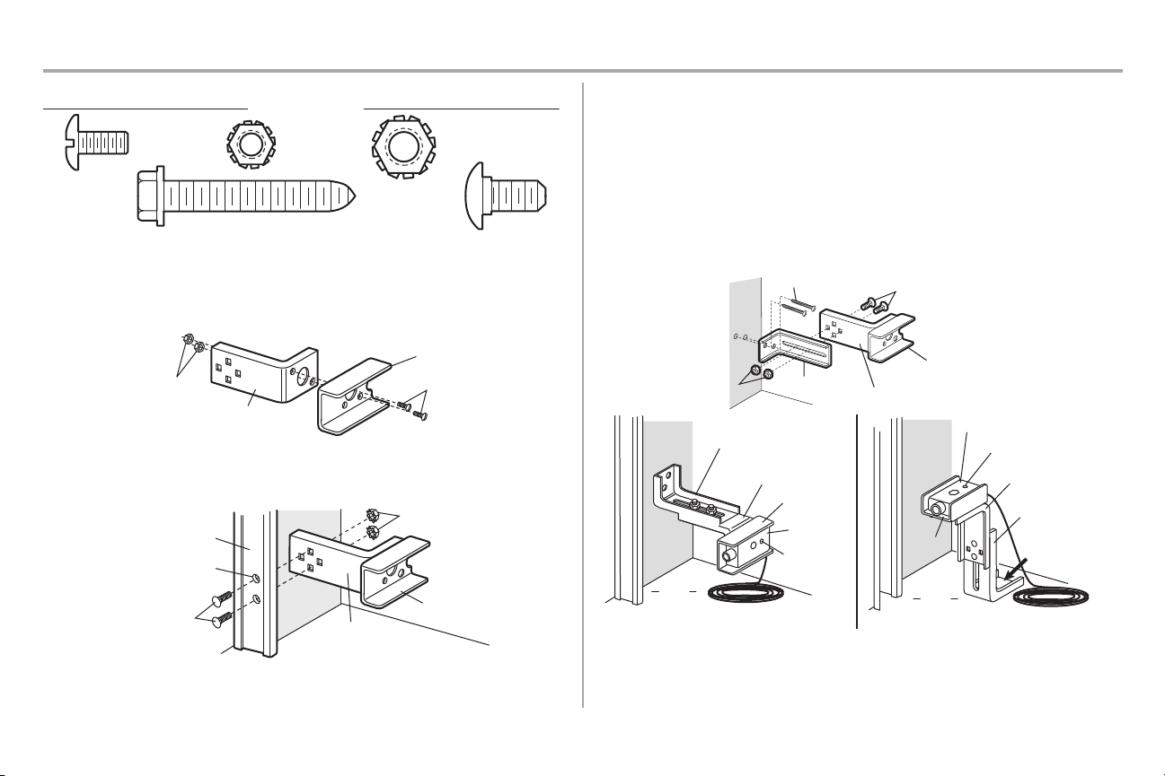
1 Assemble and Mount the Brackets
HARDWARE
Carriage Bolt
1/4"-20 x 1/2"
Lock Nut
1/4"-20
Lag Screw
1/4"x1-1/2"
Lock Nut
#10-32
Screw
#10-32x3/8"
The following instructions show recommended assembly of the bracket(s) and “C” wrap based on the wall installation
of the safety reversing sensors on each side of the door or on the door tracks themselves. There are also alternate
mounting methods which may fit your installation requirements better. Make sure the wraps and brackets are
aligned so the safety reversing sensors will face each other across the door. Mount sensors no more than
6" (15 cm) above the floor and at a width between 7'-30' (2.1 m - 9.1 m).
Fasten the “C” wraps to the mounting brackets having square holes, using hardware shown.
Mounting Bracket with Square Holes
“C” Wrap
#10-32x3/8" Screws
#10-32 Lock Nuts
DOOR TRACK INSTALLATION
Discard slotted bracket. Drill 3/8" holes in each track and fasten securely with hardware . Do not exceed 6" (15 cm)
above the floor. NOTE: Ensure the door track does not vibrate when the door is in motion. Excessive vibration can
create nuisance reversals.
Inside Wall
“C” Wrap
1/4-20x1/2"
Carriage Bolts
1/4" Lock Nuts
Door Track
Drill 3/8" Holes
Mounting Bracket
with Square Holes
WALL INSTALLATION
1. Connect each assembly to a slotted bracket, using the hardware shown. Note alignment of brackets for
left and right sides of the door.
2. Finger tighten the lock nuts
3. Use bracket mounting holes as a template to locate and drill (2) 3/16" diameter pilot holes on both sides of
the door, 4-6" (10-15 cm) above the floor. Do not exceed 6" (15 cm).
4. Attach bracket assemblies with 1/4"x1-1/2" lag screws.
5. Adjust right and left side bracket assemblies to the same distance out from mounting surface. Make sure all
door hardware obstructions are cleared. Tighten the nuts securely.
6. Center each sensor in the bracket with the lenses pointing toward each other across the door.
7. Attach the sensors to the brackets with the provided hardware. Finger tighten the receiving sensor wing
nut. Securely tighten the sending sensor wing nut.
“C” Wrap
Mounting Bracket
with Slot
Inside Wall
1/4"x1-1/2" Lag Screws
1/4"-20x1/2" Carriage Bolts
(with square shoulders)
Mounting Bracket with Square Holes
1/4"-20 Lock Nuts
Indicator Light
Inside
Wall
Mounting Bracket
with Slot
Attach with
concrete
anchors
(not provided)
Mounting Bracket
with Square Holes
“C” Wrap
Sensor with wire
Alternate Wall Mount Alternate Floor Mount
“C” Wrap
Inside
Wall
Mounting Bracket
with Square Holes
Mounting Bracket
with Slot
Sensor
with wire
Floor
Floor
Indicator
Light
Loading ...
Loading ...
Loading ...