v. 091709
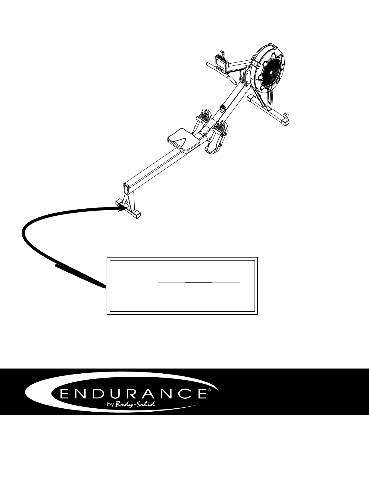
R300
Endurance
®
R300 Rower
User Manual
v. R300-103117
by Body-Solid

Table of Contents
2
CONGRATULATIONS..................................................................................3
IMPORTANT SAFETY INSTRUCTION........................................................4
SAFETY GUIDELINES.................................................................................5 - 6
ASSEMBLY INSTRUCTION.........................................................................7 - 19
OPERATING YOUR ROWER.......................................................................20 - 22
OPERATING THE CONSOLE......................................................................23 - 25
MONITORING YOUR HEART RATE............................................................28
CHEST STRAP OPERATION.......................................................................29
PART LIST....................................................................................................30 - 32
EXPLODED VIEW DIAGRAM......................................................................33

CONGRATULATIONS
3
Congratulations!!
Thank you for purchasing your new Endurance
Fan Rower.
Using state-of-the-art techniques, robust frame structure and superior
ergonomic design, Endurance Fan Rower set a new standard for excellence.
The Endurance
Fan Rower
healthy, increasing your energy levels and enhancing your lifestyle.
Endurance
wants to ensure years of quality workouts with your new Fan Rower so
we recommend that you read this manual carefully and thoroughly to fully
understand proper use and maintenance of this product. Retain this Owner’s
Manual for future reference.
Please use this Owner’s Manual to make sure that all parts have been included in
your shipment. When ordering parts, you must use the part number and description
from this Owner’s Manual. Use only Endurance
replacement parts when servicing
this machine. Failure to do so will void your warranty and could result in personal
injury.
website at www.bodysolid.com/Home/Endurance-Cardio or contact an authorized
dealer or a factory-authorized service company or contact Customer Tech Support
at one of the following:
Toll Free: 1-800-556-3113
Phone: 1-708-427-3555
Fax: 1-708-427-3556
Hours: M-F 8:30-5:00 CST
E-Mail: [email protected]
Or write to:
Endurance Service Department
1900 S. Des Plaines Ave.
Forest Park, IL 60130 USA

Before beginning any tness program, you should obtain a complete physical examination
from your physician.
Il est conseille de subir un examen medical complet avant d’entreprendre tout programme d’exercise. Si vous
avez des etourdissements ou des faiblesses, arretez les exercices immediatement.
When using exercise equipment, you should always take basic precautions,
including the following:
Read all instructions before using the R300. These instructions are written to
ensure your safety and to protect the unit.
Do not allow children on or near the equipment.
Use the equipment only for its intended purpose as described in this guide.
Do not use accessory attachments that are not recommended by the manufacturer.
Such attachments might cause injuries.
Wear proper exercise clothing and shoes for your workout, no loose clothing.
Do not overexert yourself or work to exhaustion.
If you feel any pain or abnormal symptoms, stop your workout immediately and
consult your physician.
Never operate the unit after it has been dropped or damaged.
Return the equipment to a service center for examination and repair.
Never drop or insert objects into any opening in the equipment.
Always check the unit before each use.
Make sure that all fasteners are secure and in good working condition.
Do not use the equipment outdoors or near water.
PERSONAL SAFETY DURING ASSEMBLY
Assistance is required.
Before beginning assembly, please take the time to read the instructions thoroughly.
Read each step in the assembly instructions and follow the steps in sequence.
Do not skip ahead. If you skip ahead, you may learn later that you have to
disassemble components and that you may have damaged the equipment.
Assemble and operate the R300 on a solid, level surface.
Locate the unit a few feet from the walls or furniture to provide easy access.
The R300 is designed for your enjoyment. By following these precautions and using common
sense, you will have many safe and pleasurable hours of healthful exercise with your
Endurance
R300.
After assembly, you should check all functions to ensure correct operation. If you experience
assembly. If you are unable to correct the problem, call the dealer from whom you purchased
the machine or call 1-800-556-3113 for the dealer nearest you.
Important Safety Instructions
4

Successful cardio training programs have one prominent feature in common...safety.
Cardio training has some inherent dangers, as do all physical activities.
The chance of injury can be greatly reduced or completely removed by using correct
running techniques, proper breathing, maintaining equipment in good working
condition, and by wearing the appropriate clothing.
It is highly recommended that you consult your physician before beginning
any exercise program. This is especially important for individuals over the
age of 35, or persons with pre-existing health problems.
Always warm up before starting a workout. Try to do a total body warm up
before you start. It is especially important to warm up the specic muscle
groups you are going to be using. This can be as simple as performing a
warm up set of high repetitions and light weight for each exercise.
Always wear appropriate clothing and shoes when exercising.
Wearing comfortable athletic shoes with good support and loose tting,
breathable clothing will reduce the risk of injury.
Maintaining equipment in proper operating condition is of utmost
importance for a safe cardio training program.
Read and study all warning labels on this machine. It is absolutely
necessary that you familiarize yourself and all others with the proper
operation of this machine prior to use.
Keep hands, limbs, loose clothing and long hair well out of the way of all
moving parts.
Inspect the machine daily for loose or worn parts. If a problem is found do
not allow the machine to be used until all parts are tightened or worn or
defective parts are repaired or replaced.
Safety Guidelines
5

This exercise equipment is designed and built for optimum safety for home use.
However, certain precautions always apply whenever you operate any exercise
equipment.
Be sure to read the entire manual before assembly and operation of this machine.
Also, please note the following safety precautions.
MECHANICAL SAFETY
Inspect the equipment prior to exercising to ensure that all nuts and bolts are
fully tightened before each use.
Replace any defective components immediately and/or keep the equipment out
of use until repair.
Do not use attachments not recommended by the manufacturer.
Never drop or insert an object into any opening.
Only one person may use the rower at a time.
Never activate the rower when someone is standing on the belt.
APPROPRIATE ATTIRE
Always wear appropriate clothing.
Do not wear loose clothing that might catch on any part of this rower.
Always wear non-slippery shoes while working with the rower.
Do not wear shoes with heels or leather soles.
Check the soles of your shoes and remove any dirt and embedded stones.
CHILDREN AND PETS
Most exercise equipment is not recommended for small children.
Children should not use the equipment unless they are under strict adult supervision.
Exercise equipment has many moving parts.
In the interest of safety, keep others (especially children and pets) at a safe distance
while you exercise.
FCC WARNING - POSSIBLE RADIO/TELEVISION INTERFERENCE
NOTE: This equipment has been tested and found to comply with Part 15 of the FCC rules. These limits are designed to
expressly approved by the party responsible for the compliance could void the user’s authority to operate the equipment.
This equipment generates, uses and can radiate radio frequency energy and, if not installed and used in accordance
with the instructions, may cause harmful interference to radio communications. However, there is no guarantee that the
interference will not occur in a particular installation.
If this equipment does cause harmful radio interference to radio or television reception, which can be determined by
measures:
Class R (Residential): Private or non-commercial use
Safety Guidelines
6
Assembly of the R300 takes professional installers about 1/2 hour to complete. If this
time.
Professional installers are highly recommended!
However, if you acquire the appropriate tools, obtain assistance, and follow the
assembly steps sequentially, the process will take time, but is fairly easy.
ASSEMBLY TIPS
Read all “NOTES” on each page before beginning each step.
While you may be able to assemble the R300 using the illustrations only, important safety
notes and other tips are included in the text.
Some pieces may have extra holes that you will not use. Use only those holes indicated in
the instructions and illustrations.
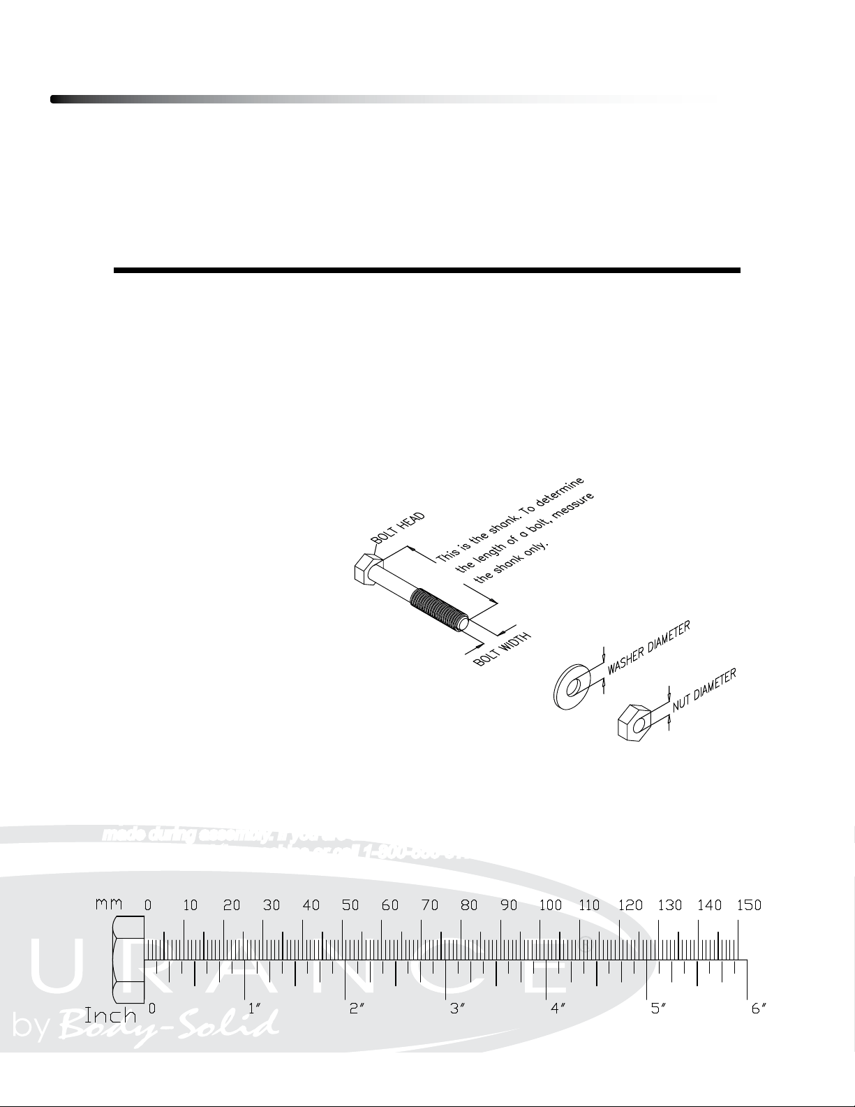
NOTE: To nd out the length of a particular bolt, measure its shank (the long, narrow part
beneath the head).
Refer to the following diagram:
Do not fully tighten bolts until instructed to do so.
NOTE: After assembly, you should check all functions to ensure correct operation. If you
experience problems, rst recheck the assembly instructions to locate any possible errors
made during assembly. If you are unable to correct the problem, call the dealer from whom
you purchased the machine or call 1-800-556-3113 for the dealer nearest you.
Assembly Instructions
7

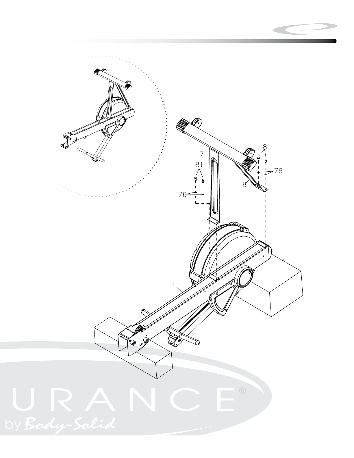
Be careful to assemble all components
in the sequence they are presented.
Note: Do not fully tighten bolts until instructed
A. Attach Front Support Legs (#7 & #8) to Front Stabilizer (#4) using:
M6x16mm Socket Head Cap Screw (#81), QTY: 4
M6 Flat Washer (#76), QTY: 4
8
Step 1
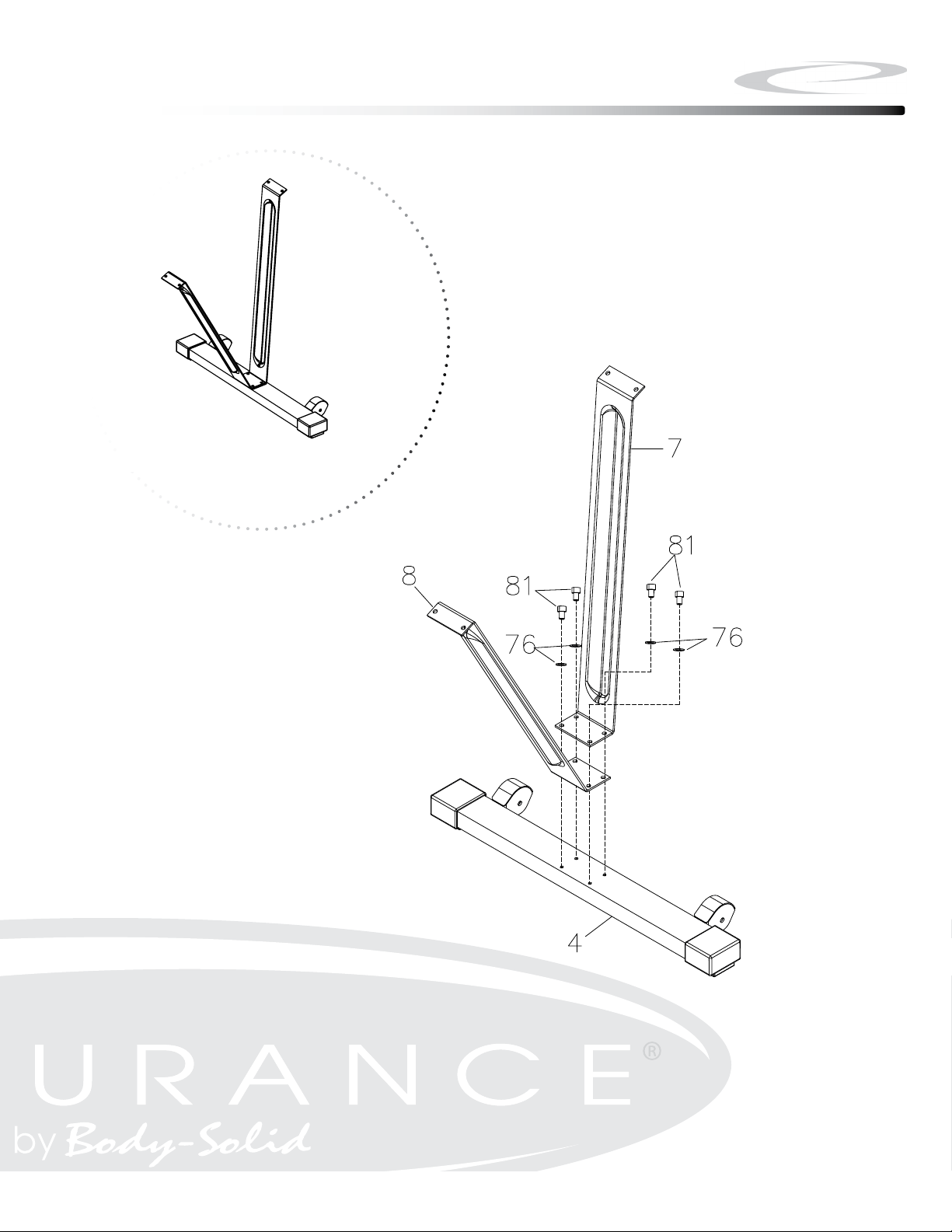
Step 1
9
Above shows STEP 1 assembled and completed.

Be careful to assemble all components
in the sequence they are presented.
Note: Fully tighten bolts at the End of each Step.
A. Attach Front Support Legs (#7 & #8) to Main Frame (#1) using:
M6x16mm Socket Head Cap Screw (#81), QTY: 4
M6 Flat Washer (#76), QTY: 4
10
Step 2
Step 2
11
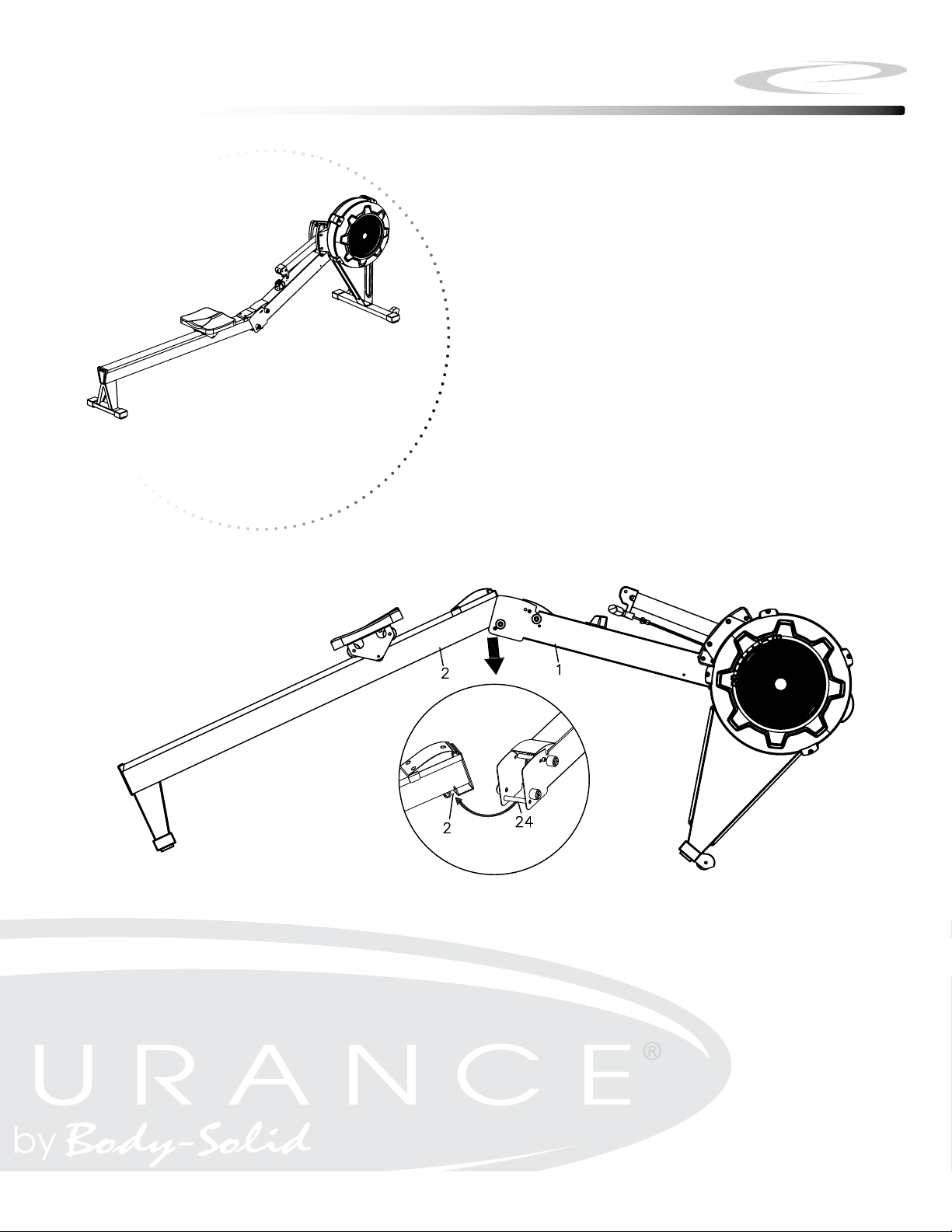
Above shows STEP 2 assembled and completed.

Be careful to assemble all components
in the sequence they are presented.
Note: Fully tighten bolts at the End of each Step.
A. Lift Up the Main Frame (#1) and Rail Frame (#2), then insert Rail Fram (#2)
into the Main Frame (#1). Fit the Shaft (#24) on the Main Frame (#1) into
the gap of the Rail Frame (#2).
12
Step 3
Step 3
13
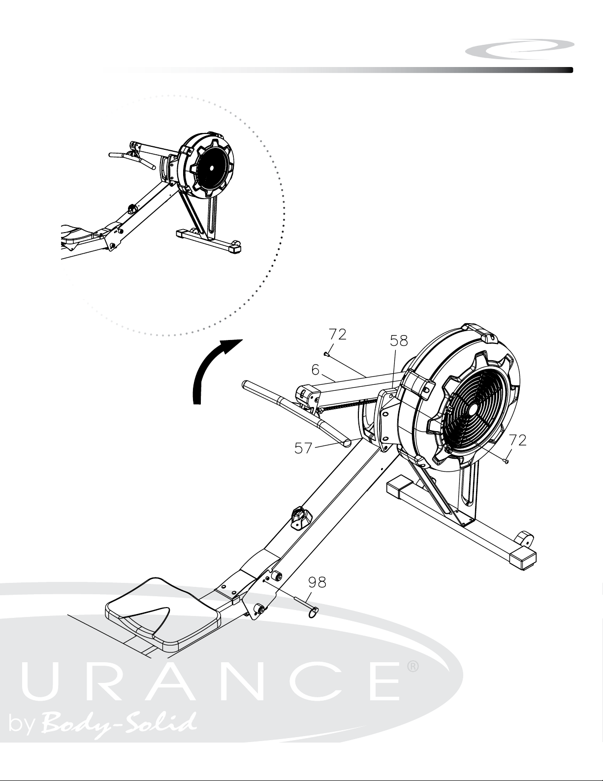
Above shows STEP 3 assembled and completed.

Be careful to assemble all components
in the sequence they are presented.
Note: Fully tighten bolts at the End of each Step.
A. Insert the Pull Pin (#98) into the Main Frame (#1) and Rail Frame (#2).
B. Attach Console Monitor Post (#6) to the Side Covers (#57 & #58) using:
M6x10mm Phillips Head Screw (#72), QTY: 2
14
Step 4
Step 4
15
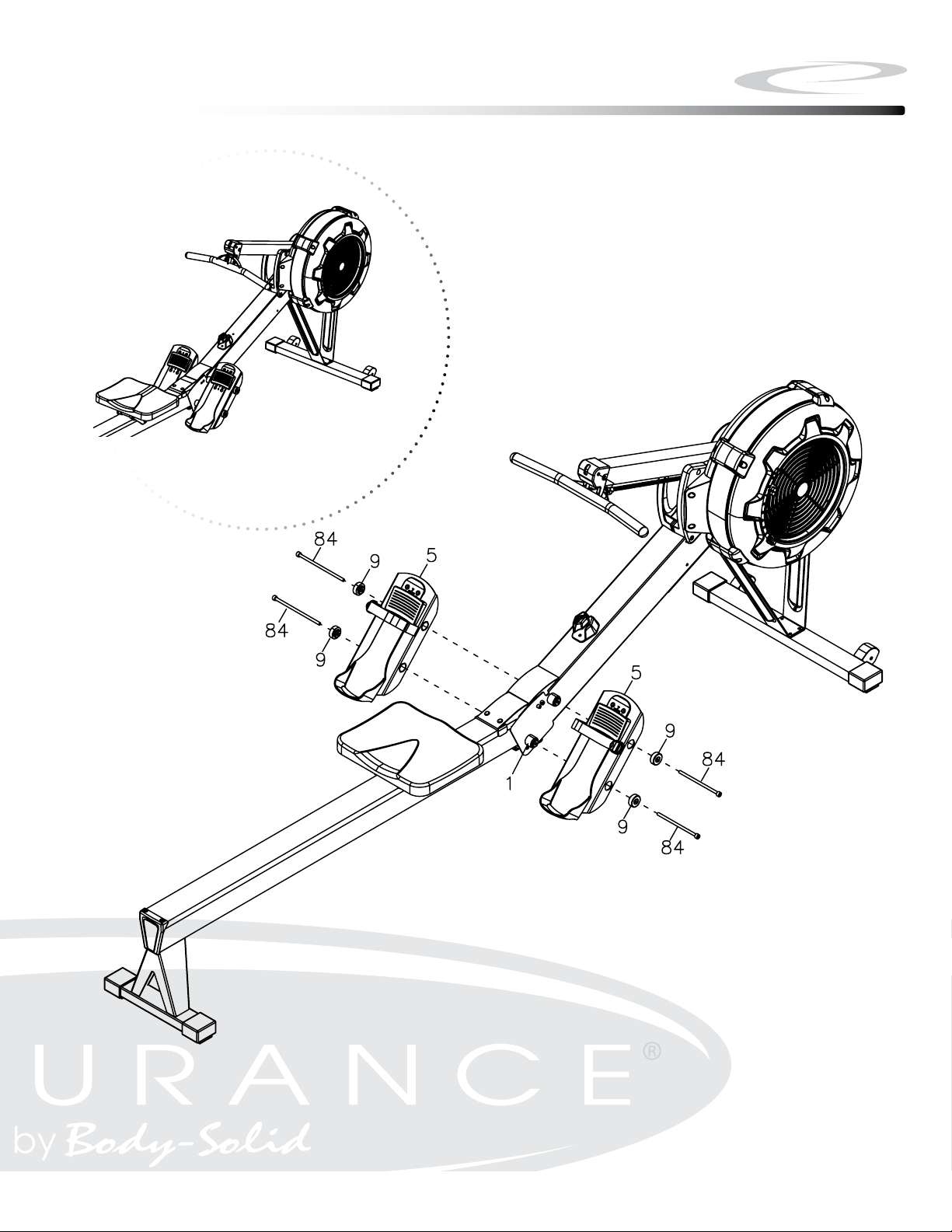
Above shows STEP 4 assembled and completed.

Be careful to assemble all components
in the sequence they are presented.
Note: Fully tighten bolts at the End of each Step.
A. Attach Pedal Support Plates (#5) to the Main Frame (#1) using:
M8x150mm Socket Head Cap Screw (#84), QTY: 4
Foot Pedal End Cap (#9), QTY: 4
16
Step 5
Step 5
17
Above shows STEP 5 assembled and completed.

Be careful to assemble all components
in the sequence they are presented.
Note: Fully tighten bolts at the End of each Step.
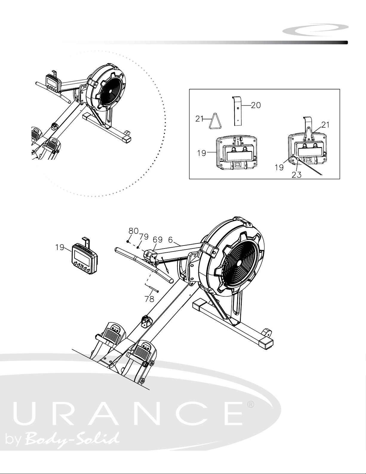
A. Attach Cell Phone Bracket (#20) to the Console Monitor (#19) using
Rubber Band (#21).
B. Attach the Console Monitor (#19) to the Console Mounting Bracket
(#69) using:
M8x75mm Button Head Cap Screw (#78), QTY: 1
M8 Flat Washer (#79), QTY: 1
M8 Nylon Lock Nut (#80), QTY: 1
C. Connect Sensor Cable (#23) into the back of the Console Monitor (#19).
18
Step 6
Step 6
19
Above shows STEP 6 assembled and completed.
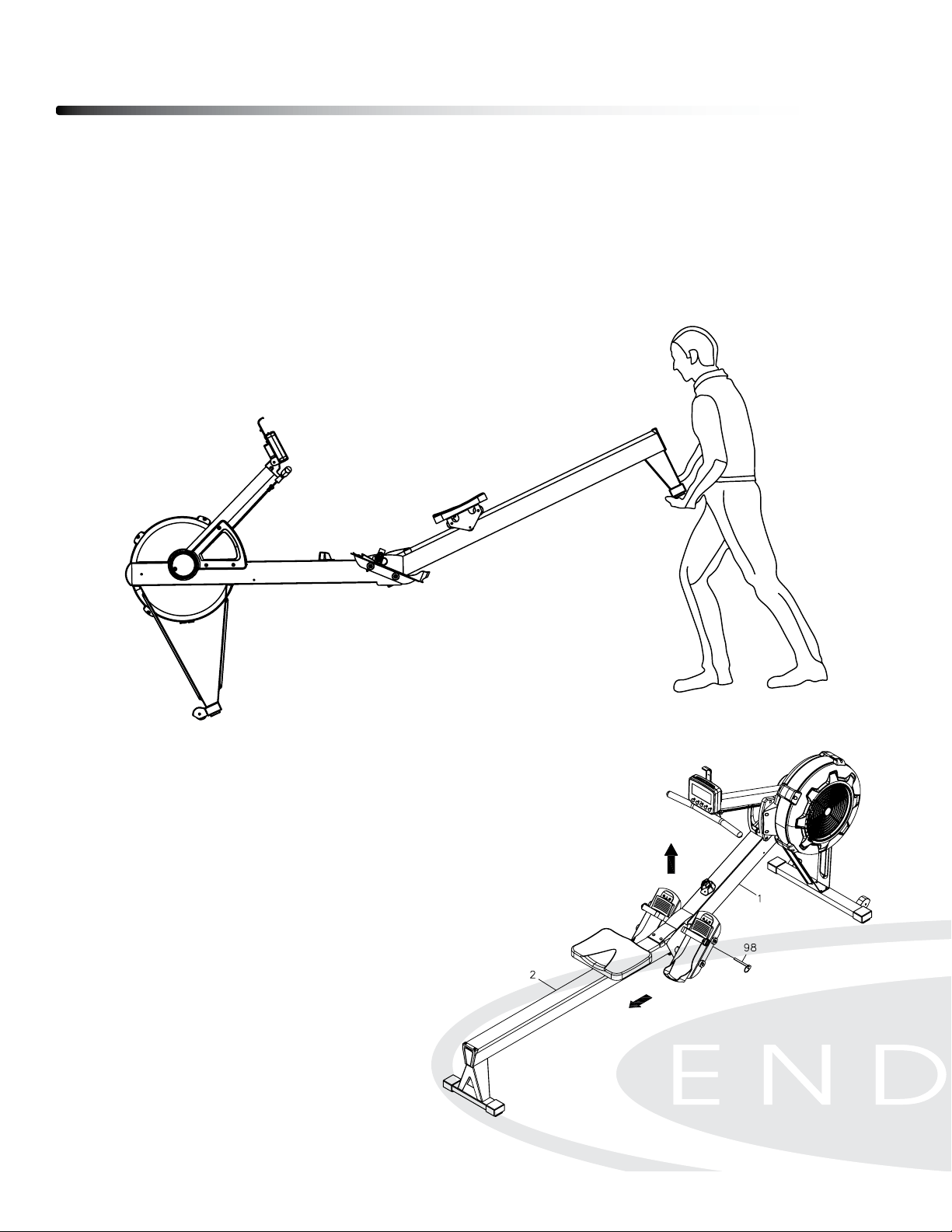
MOVING THE ROWER
The rower is easy to move around safely.
To move the rower:
1. Lift the rear of the rower
2. Roll the rower on its front transport wheels to the desire location.
3. Gently lower the rear of the rower to the ground level
Operating your Rower
20
STORING THE ROWER
The rower can be seprated to minimize the unit size for storage.
1. Remove the Pull Pin (#98).
2. Lift up the Main Frame (#1) and pull out the Rail Frame (#2)
3. Insert the Pull Pin (#98) back to the hole in the Main Frame (#1)
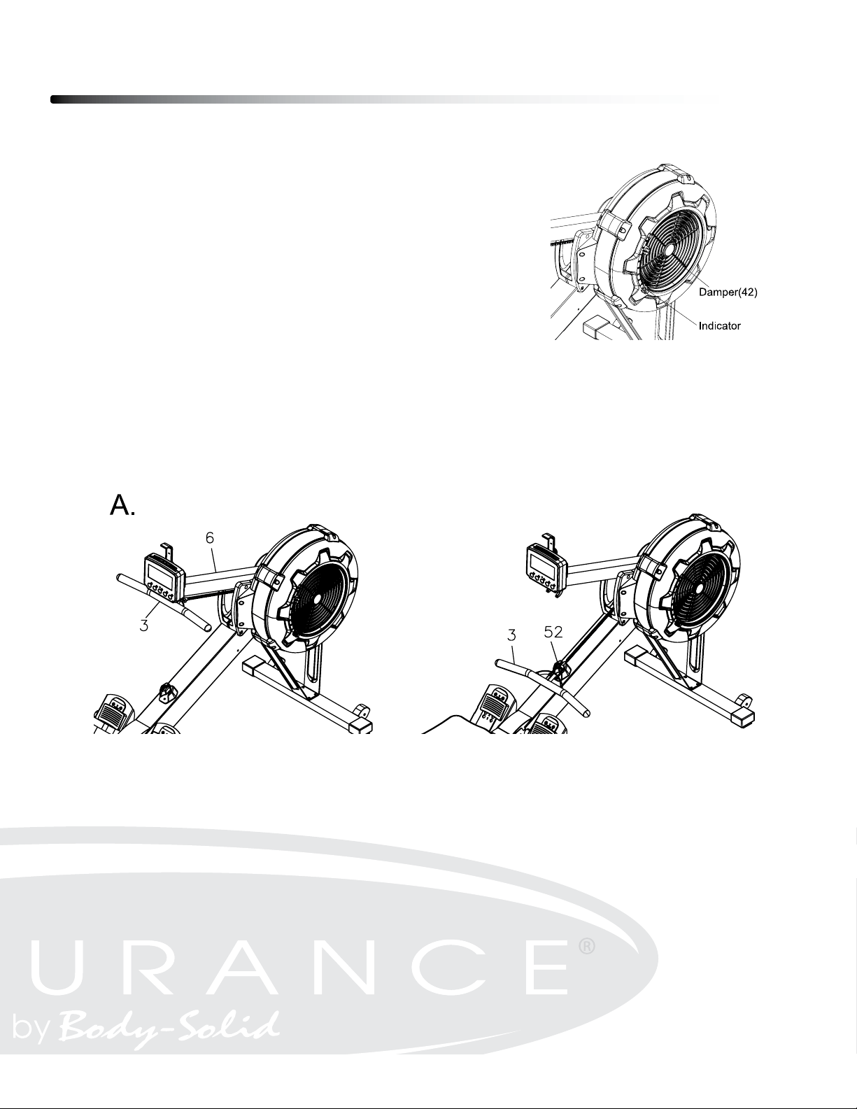
DAMPER ADJUSTMENT
There is a damper adjustment on the right side of the fan
Shroud. The indicator can be moved up/down to adjust
the damper. #1 is the lowest setting, #9 is the highest
setting.
HANDLEBAR POSITION
Handlebar (#3) can be placed on the hook of the Console Monitor Post (#6) or it can be
placed on the Handlebar Holder (#52).
Operating your Rower
21
Operating your Rower
22
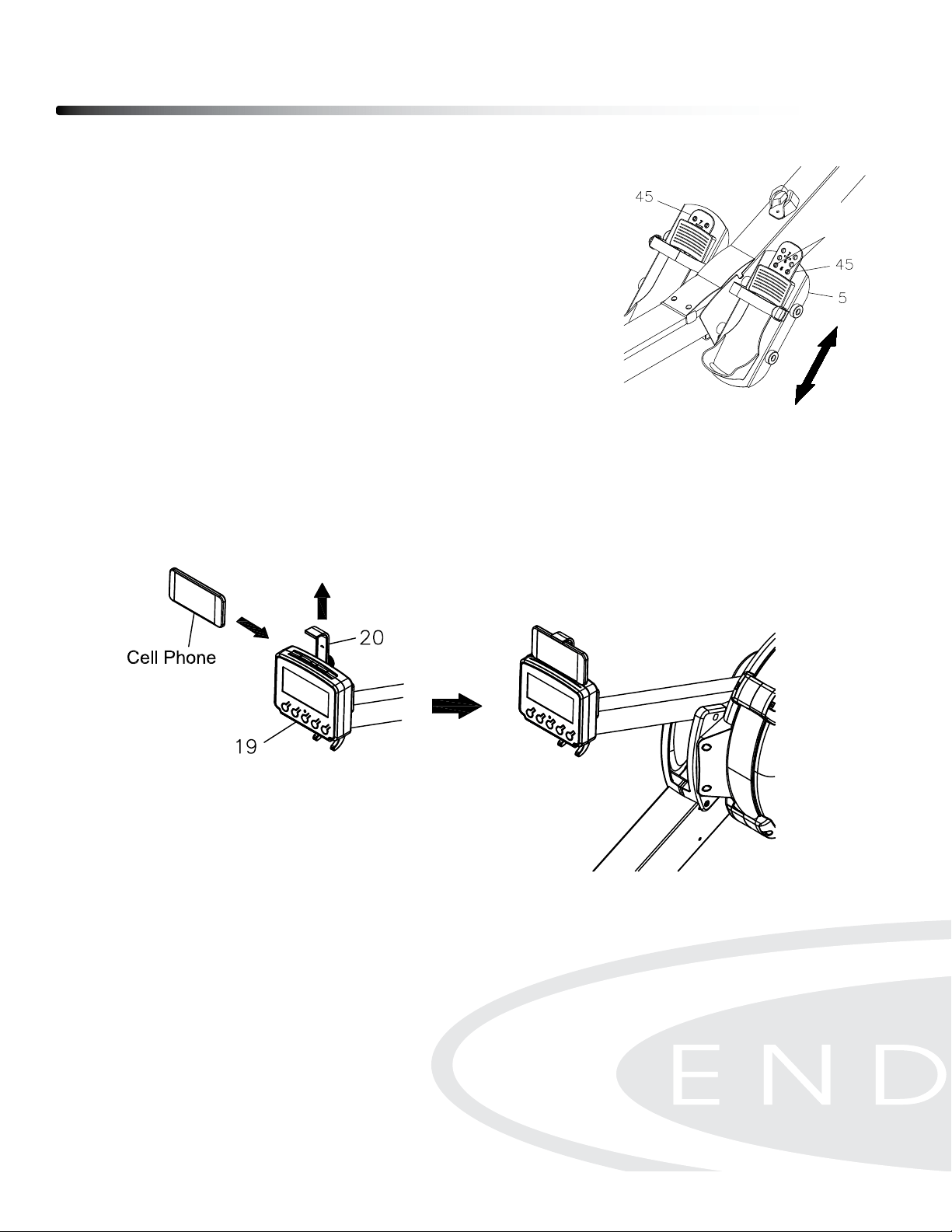
FOOT PEDAL ADJUSTMENT
1. Pull the Foot Pedal (#45) out of the two bulges of the Pedal
Support Plate (#5).
2. Lower or raised the Foot Pedal to the desired location.
3. Lock the Foot Pedal (#45) by pressing the adjustment
holes onto the Bulges.
CELL PHONE HOLDER.
Slide the cell phone into the space between the Cell Phone Bracket (#20) and Console
Monitor (#19) by moving the Cell Phone Bracket (#20) up or down.
Operating the Console
23
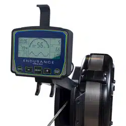
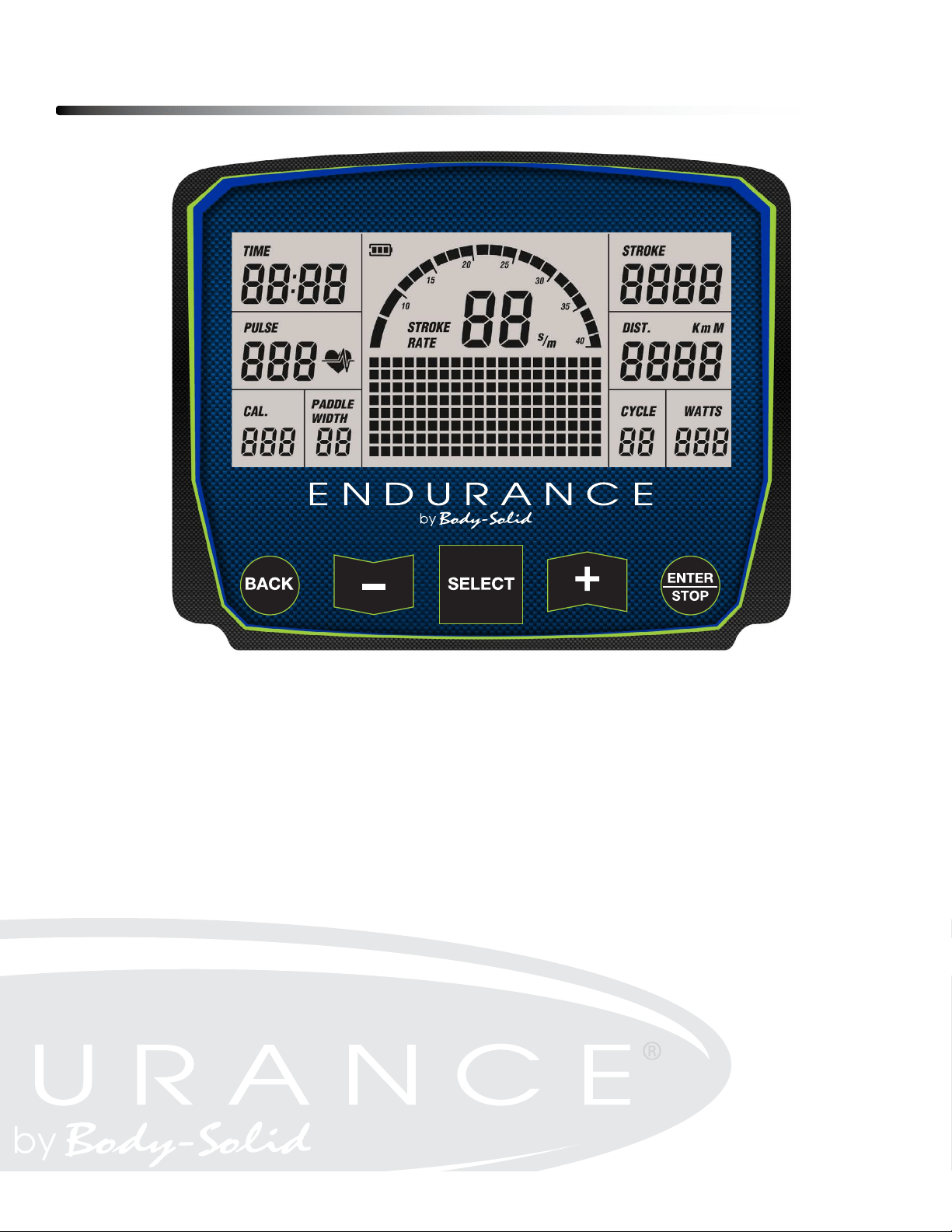
CONSOLE DISPLAY
TIME:
1:00 to 99:00 minutes
- Displays the time during exercise.
STROKE:
- Display the total number of stroke during exercise
PULSE:
- Display the heart rate from 40 to 220 beats per minute during exercise. To use this
function, the user must wear the Heart Rate Chest Strap.

CALORIES:
can be set from 10 to 999 cals
PADDLE WIDTH:
- Display the distance per stroke.
STROKE RATE:
- Display the current stroke per minute during exerices.
DISTANCE:
value can be set from 500 to 9999.
CYCLE:
program. The value can be set from 1 to 99.
- Value will count down from the preset value during INTERVAL program.
WATTS:
- Display the amount of power generated at any moment during the workout.
CONSOLE BUTTONS
BACK BUTTON:
- Press the button to return to the previous program
UP & DOWN BUTTONS:
- Press the buttons to adjust the value in the program.
SELECT BUTTON:
- In IDLE mode, press the button the select through each program options.
The program options are QUICK START, TIME, DISTANCE, CALORIES, PLAY THE
GAME, and INTERVAL PROGRAMS of 20/10, 10/20 & 10/10.
Operating the Console
24

ENTER/STOP BUTTON:
- Press and hold the button for three seconds to reset the console program.
- Press the button to pause the program during workout.
INITIAL SETUP
POWER ON:
- Move the Handlebar or press any button.
POWER OFF:
- In IDLE mode, if there is no activitiy detected for 20 seconds, the console will shut
- During all programs except 20/10, 10/20, 10/10 interval programs, the console will
activity detected for two minutes.
METRIC & STANDARD UNIT:
The initial factory setting is in “Miles”. To toggle between Miles and Kilometers, press
BATTERY INSTALLATION:
Console operates on two Size C batteries. The battery compartment is on the back
of the console. Battery is not included.
PROGRAMS
The Console Monitor has eight programs: QUICK START, TIME, DISTANCE,
CALORIES, PLAY THE GAME, and INTERVAL PROGRAMS of 20/10, 10/20 & 10/10.
Operating the Console
25

1. QUICK START PROGRAM
To Quick Start the program, you can pull on the Handlebar (#30) to start. All fuction
values fo the console will count up.
For the other seven programs, press the “BACK” button to enter IDLE mode. Or
press and hold the ”ENTER/STOP” button for three second to restart the console.
Use the “SELECT” button to toggle between programs. Use “UP” & “DOWN”
Buttons to adjust the value and press “ENTER/STOP”
2. DISTANCE PROGRAM
During the workout, the “DISTANCE” program will count down from preset value.
The program will start once the user pulls the Handlebar. When the program is
“WINNER” with an audible alarm. Press the “BACK”
button to go to the IDLE mode.
3. TIME PROGRAM
During the workout, the “TIME” program will count down from preset value. The
the monitor will end with an audible alarm. Press the “BACK” button to go to the
IDLE mode.
4. CALORIES PROGRAM
During the workout, the “CALORIES” program will count down from preset value.
The program will start once the user pulls the Handlebar. When the program is
“END” with an audible alarm. Press the “BACK”
button to go to the IDLE mode.
5. GAME PROGRAM
When the “GAME” program is selected, The program will start once the user pulls
the Handlebar. There is no presetting value to be entered. When the program is
“BACK”
button to go to the IDLE mode.
Operating the Console
24

6. 20/10 INTERVAL PROGRAM
When it is in the “20/10 INTERVAL” program, the console monitor will display
“8” for presetting value of cycle. The user can use “UP” & “DOWN” buttons
to input the value from 1 to 99. The user will workout for 20 seconds and then rest
alarm. Press the “BACK” button to go to the IDLE mode.
7. 10/20 INTERVAL PROGRAM
When it is in the “10/20 INTERVAL” program, the console monitor will display
“8” for presetting value of cycle. The user can use “UP” & “DOWN” buttons
to input the value from 1 to 99. The user will workout for 10 seconds and then rest
for 20 seconds. The program will start once the user pulls the Handlebar. When the
“BACK”
button to go to the IDLE mode.
8. 10/10 INTERVAL PROGRAM
When it is in the “10/10 INTERVAL” program, the console monitor will display
“8” for presetting value of cycle. The user can use “UP” & “DOWN” buttons
to input the value from 1 to 99 for number of cycle, workout time and rest time. The
the monitor will end with an audible alarm. Press the “BACK” button to go to the
IDLE mode.
Operating the Console
25
Monitoring Your Heart Rate
28
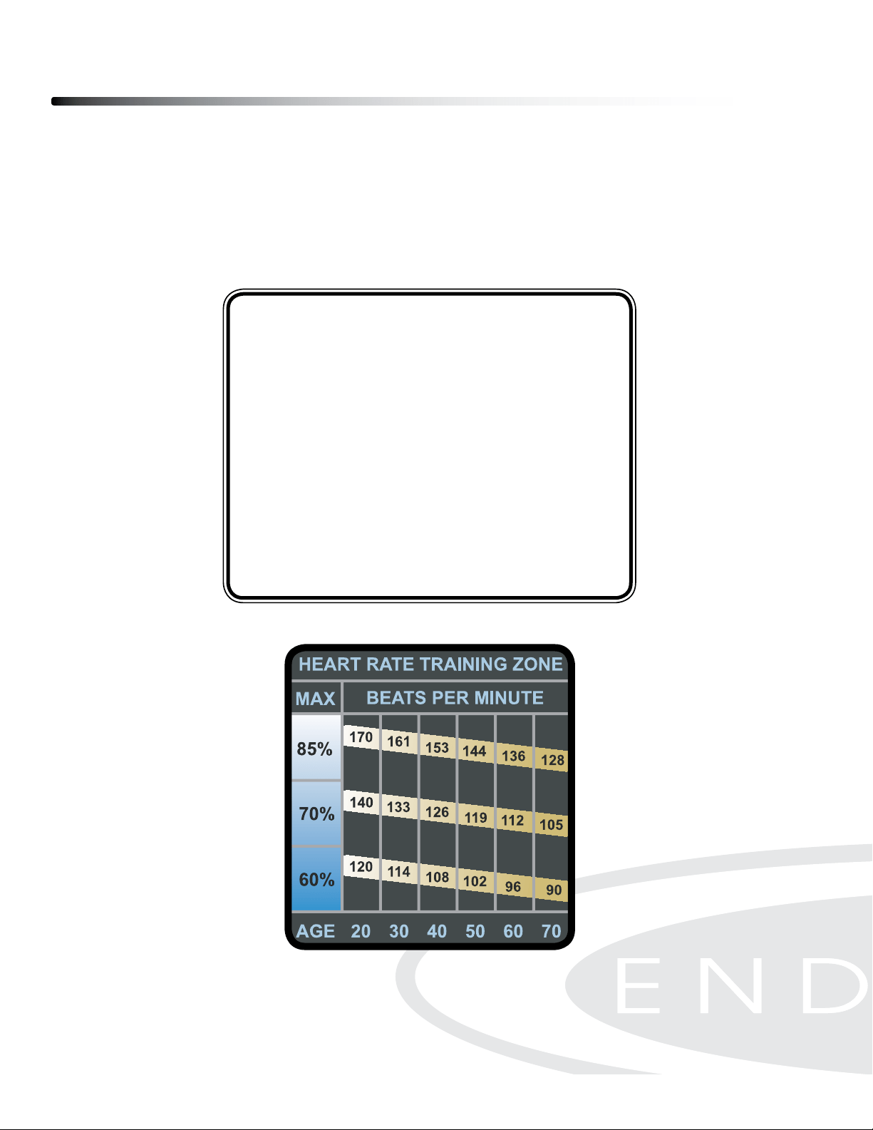
FITNESS SAFETY
The Heart Rate chart indicates average rate zones for dierent ages. A variety of dif-
ferent factors (including medication, emotional state, temperature and other con-
ditions) can aect the target heart rate zone that is best for you. Your physician or
health care professional can help you determine the exercise intensity that is appro-
priate for your age and condition.
(MHR) = Maximum Heart Rate
(THR) = Target Heart Rate
220 - Age = Maximum Heart Rate (MHZ)
MHZ x .60 = 60% of your Maximum Heart Rate.
MHZ x .75 = 75% of your Maximum Heart Rate.
For example, if you are 30 years old, your calculations will be as follows:
220 - 30 = 190
190 x .60 = 114 (Low End or 60% of MHZ)
190 x .75 = 142 (High End or 75% of MHZ)
30 Year-Old (THR) Target Heart Rate would be 114-142
Maximum Heart Rate (MHR)
Heart Rate Training Zone
Chest Strap Operation
29
Your Endurance
®
Fan Rower has the capability to determine Heart Rate with the use
of a Heart Rate Chest Strap. A Heart Rate Chest Strap can be purchased
seperately.
It is suggested for the Chest Strap Transmitter that you position the transmitter as
close to your heart as possible, against the skin, 1-2 inches below the pectoral
muscles. For best results, moisten the back of the transmitter for better contact.
SAFETY PRECAUTIONS AND TIPS FOR CHEST STRAP
1. It is the owner’s responsibility to ensure that all users of this unit have read the
Owner’s Manual and are familiar with warnings and safety precautions.
2. Do not place chest strap near devices that generate large magnetic elds. TV sets,
electric motors, radios, and high voltage power lines can aect the transmitter’s
performance. These items can interfere with the heart rate signal and possibly
aect the heart rate readings on the console.
3. Handle the Chest Strap with care. Dropping the transmitter might cause damage
that could void the warranty.
4. Do not use the chest strap if you have a cardiac pacemaker or if your are taking
medications for a heart condition. Medication or electrical pulses from the pace-
maker can interfere with accurate heart rate readings.
5. Do not bend the strips inside the chest strap. This can cause the chest strap to
loose conductivity.
6. The chest strap has batteries that need to be replaced periodically. A faulty bat-
tery can cause inaccurate reading.
HR Chest Strap for Endurance
®
models

Part List
Part numbers are required when ordering parts.
30
PART# QTY DESCRIPTION
1 1 Main Frame
2 1 Rail Frame
3 1 Handlebar
4 1 Front Stabilizer
5 2 Pedal Support Plate
6 1 Console Monitor Post
7 1 Front Support Leg A
8 1 Front Support Leg B
9 4 Foot Pedal End Cap
10 1 Seat Carriage
11 1 Fan
12 2 Bungee Cord Hook
13 1 Chain Bracket
14 1 Rail
15 1 Perforated Steel Mesh
16 6 Spacer,
ø8.2xø12x3.2mm
17 2 Spacer,
ø8.2xø12x71.6mm
18 1 Spacer,
ø6.2xø10x15.5mm
19 1 Console Monitor
20 1 Cell Phone Bracket
21 1 Rubber Band
22 1 Generator
23 1 Sensor Cable
24 2 Shaft,
M6x
ø12x80mm
25
3 Shaft, M6x
ø10x76.5mm
26 1 Fan Axle
27 1 Hook Connector
28 1 Chain Connector
29 1 U Bolt
30 1 Inner Spacer
31 1 outer Collar
32 1 Bearing 6003RS
33 6 Bearing 608ZZ
34 3 Bearing 6201RS
35 1 One Way Bearing HF2016
36 1 Chain
37 1 Sprocket
38 1 Bungee Cord
39 4 Bungee Cord Pulley
40 2 Chaing Roller
41 8 Bearing 6000ZZ

Part numbers are required when ordering parts.
Part List
31
PART# QTY DESCRIPTION
42 1 Damper
43 1 Right Fan Shroud
44 1 Left Fan Shroud
45 2 Foot Pedal
46 2 Foot Pedal Holder
47 2 Pedal Strap
48 2 Spacer,
ø10xø16x30.5mm
49 1 Pulley
Spacer,
ø10xø16x26.5mm
50 2 Pulley Bushing
51 1 Seat
52 1 Handlebar Holder
53 1 Upper Joint Cover
54 1 Lower Joint Cover
55 1 Generator Base
56 1 Damper Cap
57 1 Left Side Cover
58 1 Right Side Cover
59 4 Foot Cap
60 2 Steel Plate
61 1 Bushing 6001
62 1 Bushing 6003
63 2 Guide Roller
64 4 Seat Roller
65 2 Roller Sleeve
66 2 Transport Wheel
67 1 Rail End Cap
68 1 Main Frame Top Cap
69 1 Console Mounting Bracket
70 1 Bottom Cover
71 3 Plastic Washer,
ø10.2xø14x1mm
72 16 Phillips Head Screw, M6x10mm
73 7 Lock Washer, Internal Tooth M6
74 4 Nylon Lock Nut, M6
75 11 Phillips Head Screw, ST4.2x10mm
76 24 Flat Washer, M6
77 2 Socket Head Cap Screw, M8x65mm
78 1 Button Head Cap Screw, M8x75mm
79 9 Flat Washer, M8
80 9 Nylon Lock Nut, M8
81 8 Socket Head Cap Screw, M6x16mm

Part List
Part numbers are required when ordering parts.
32
PART# QTY DESCRIPTION
82 2 Socket Head Cap Screw, M8x40mm
83 2 Phillips Flat Head Screw, M6x16mm
84 4 Socket Head Cap Screw, M8x150mm
85 2 Socket Head Cap Screw, M8x110mm
86 2 Button Head Cap Screw, M8x25mm
87 4 Lock Washer, M8
88 3 Phillips Head Screw, ST4.2x16mm
89 2 Phillips Head Screw,, M5x8mm
90 4 Socket Head Cap Screw, M5x92mm
91 6 Hex Nut, M5
92 2 Chain Hook
93 1 Elastic Ring
94 2 Nylon Lock Nut, M10
95 6 Phillips Head Screw, ST4.2x6mm
96 1 Phillips Head Screw, M4x45mm
97 1 Hex Nut, M4
98 1 Pull Pin
99 14 Socket Head Cap Screw, M6x16mm
100 2 Phillips Head Screw, M6x30mm
101 7 Phillips Head Screw, M6x10mm
102 1 Screwdriver
103 1 Allen Wrench, 6mm
104 1 Wrench
105 2 Hex Nut, M6
106 2 PU Spacer
107 1 Plug
108 1 Bearing, 6001RS
109 3 Balance Weight
110 1 Bearing Bushing
111 3 Socket Head Cap Screw, M4x12mm
112 2 Washer, ø12xø3.5x1mm
113 2 Phillips Head Screw, ST3.0x12mm
114 1 Allen Wrench, 5mm
115 1 Magnet
116 2 Stopper Bumper
117 2 Socket Head Cap Screw, M8x20mm
118 1 Stopper Bracket
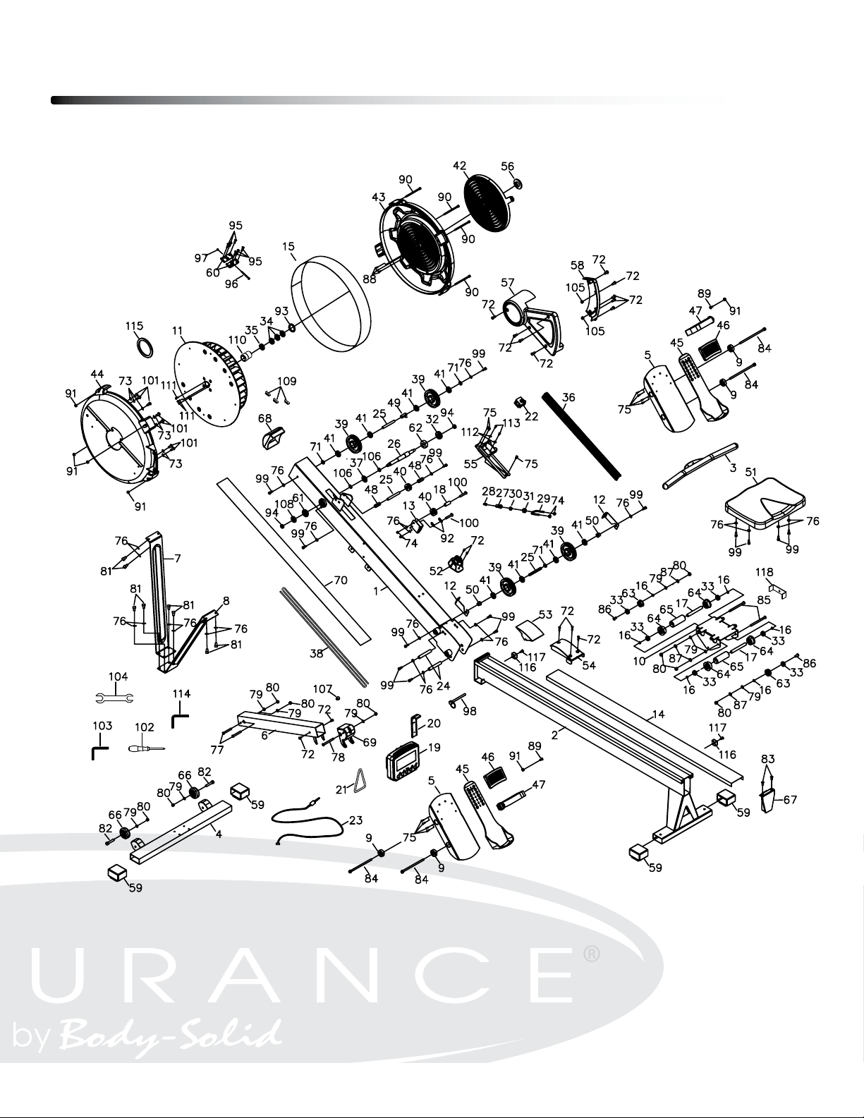
Exploded View Diagram
33
c
Copyright 2009. Body-Solid. All rights reserved. Body-Solid reserves the right to change design and specications when we feel it will improve the product.
Body-Solid machines maintain several patented and patent pending features and designs. All rights reserved on all design patents and utility patents.
Customer Tech Support Hotline
Toll Free: 1-800-556-3113
Phone: 1-708-427-3555
Fax: 1-708-427-3556
Hours: M-F 8:30-5:00 CST
E-Mail: service@bodysolid.com
Serial Number is Located on the Frame
Model Name
:
R300
Purchase Date
: _______________________________
Serial Number
: 013438-_______________________
