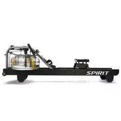

XRW600 Rower
OWNER’S MANUAL

3
TABLE OF CONTENTS
5 IMPORTANT SAFETY INSTRUCTIONS
6 IMPORTANT ELECTRICAL INSTRUCTIONS
7 IMPORTANT OPERATION INSTRUCTIONS
7 PRODUCT REGISTRATION
8 XRW600 ASSEMBLY INSTRUCTIONS
14 CONSOLE OPERATION
19 PROGRAMMABLE FEATURES
34 USING HEART RATE TRANSMITTER
37 GENERAL MAINTENANCE
38 MANUFACTURER’S LIMITED WARRANTY
Thank you for purchasing our product, please save these instructions. Please do not perform or attempt any
customizing, adjustments, repair or maintenance that is not described in this manual.
4
Congratulations on your new Rower and welcome to the Spirit Fitness family!
Thank you for your purchase of this quality Rower from Spirit Fitness. Your new Rower was manufactured by one of the
leading tness manufacturers in the world and is backed by one of the most comprehensive warranties available. Through
your dealer, Spirit Fitness will do all we can to make your ownership experience as pleasant as possible for many years to
come. If not purchased direct from Spirit Fitness, the local dealership where you purchased this Rower is your administrator
for all Spirit Fitness warranty and service needs. Their responsibility is to provide you with the technical knowledge and service
personnel to make your experience more informed and any difculties easier to remedy.
Please take a moment at this time to record the name of the dealer, their telephone number, and the date of purchase below
to make any future, needed contact easy. We appreciate your support and we will always remember that you are the reason
that we are in business.
Yours in Health,
Spirit Fitness
NAME OF DEALER _____________________________________
DEALER PHONE # _____________________________________
PURCHASE DATE _____________________________________

5
Important Safety Instructions
WARNING
When using an electrical appliance, basic precautions should
always be followed, including the following:
Read all instructions before using this appliance.
DANGER - To reduce the risk of electric shock:
Always unplug this appliance from the electrical outlet
immediately after using and before cleaning.
WARNING - To reduce the risk of burns, re, electric
shock, or injury to persons, install the Rower on a at level
surface with access to a 110-volt, 15-amp grounded outlet
with only the Rower plugged into the circuit.
DO NOT USE AN EXTENSION CORD UNLESS IT IS A 14AWG OR
BETTER, WITH ONLY ONE OUTLET ON THE END:
• Do not operate Rower on deeply padded, plush or
shag carpet. Damage to both carpet and Rower
may result.
• Keep children away from the Rower. There are obvious
pinch points and other caution areas that can cause
harm.
• Keep hands away from all moving parts.
• Never operate the Rower if it has a damaged cord
or plug. If the Rower is not working properly, call your
dealer.
• Keep the cord away from heated surfaces.
• Do not operate where aerosol spray products are
being used or where oxygen is being administered.
Sparks from the motor may ignite a highly gaseous
environment.
• Never drop or insert any object into any openings.
• Do not use outdoors.
• To disconnect, turn all controls to the off position, then
remove the plug from the outlet.
• Do not attempt to use your Rower for any purpose
other than for the purpose it is intended.
• Use of a chest strap transmitter (sold separately) is an
accurate method of heart rate analysis. Various factors,
including the user’s movement, may affect the accuracy
of heart rate readings.
• Wear proper shoes. High heels, dress shoes, sandals
or bare feet are not suitable for use on your Rower.
Quality athletic shoes are recommended to avoid
leg fatigue.
• This exercise equipment is not intended for use by
persons with reduced physical, sensory or mental
capabilities, or lack of experience and knowledge.
• Keep children under the age of 13 away from this
machine.
SAVE THESE INSTRUCTIONS - THINK SAFETY!
WARNING: This product can expose you to chemicals
including Toluene and Acrylamide which are known to the
State of California to cause cancer and birth defects or
other reproductive harm.
For more information go to www.P65Warnings.ca.gov
6
Important Electrical Instructions
WARNING
NEVER remove any cover without rst disconnecting AC power.
If voltage varies by ten percent (10%) or more, the performance
of your Rower may be affected. Such conditions are not covered
under your warranty. If you suspect the voltage is low, contact your
local power company or a licensed electrician for proper testing.
NEVER expose this Rower to rain or moisture. This product is
NOT designed for use outdoors, near a pool or spa, or in any
other high humidity environment. The operating temperature
specication is 40 to 120 degrees Fahrenheit, and humidity is 95%
non-condensing (no water drops forming on surfaces).
Circuit Breakers: Some circuit breakers used in homes are not
rated for high inrush currents that can occur when a Rower is rst
turned on or even during use. If your Rower is tripping the house
circuit breaker (even though it is the proper current rating) but
the circuit breaker on the Rower itself does not trip, you will need
to replace the home breaker with a high inrush type. This is not
a warranty defect. This is a condition we as a manufacture have
no ability to control. This part is available through most electrical
supply stores. Examples: Grainger part # 1D237, or available online
at www.squared.com part #QO120HM. The electrical outlet used
should have a dedicated 15 amp circuit breaker.
Grounding Instructions
This product must be grounded. If the Rower should
malfunction or breakdown, grounding provides a path of least
resistance for electric current, reducing the risk of electric shock.
This product is equipped with a cord having an equipment-
grounding plug. The plug must be plugged into an appropriate
outlet that is properly installed and grounded in accordance with
all local codes and ordinances.
DANGER - Improper connection of the equipment-
grounding conductor can result in a risk of electric shock.
Check with a qualied electrician or serviceman if you are
in doubt as to whether the product is properly grounded.
Do not modify the plug provided with the product if it will
not t the outlet; have a proper outlet installed by a qualied
electrician.
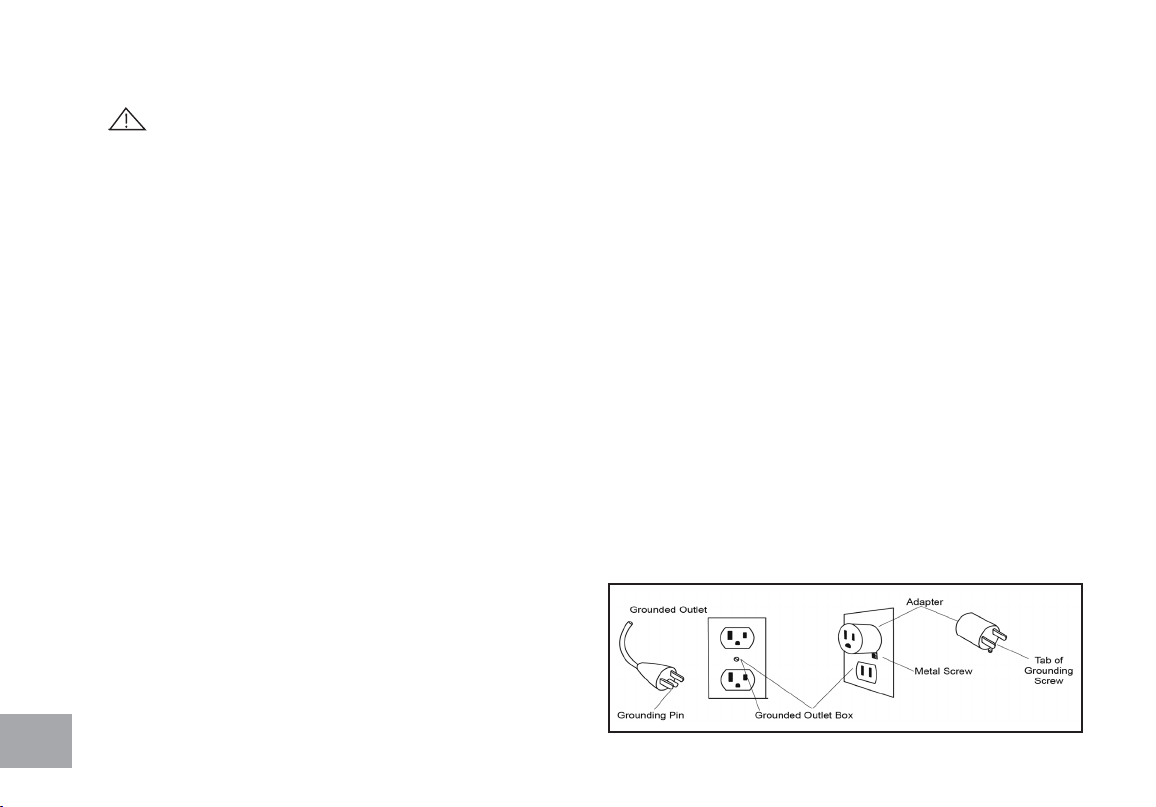
This product is for use on a nominal 110-volt/15 amp
dedicated circuit, and has a grounding plug that looks like the
plug illustrated below. A temporary adapter that looks like
the adapter illustrated below may be used to connect this
plug to a 2-pole receptacle as shown below if a properly
grounded outlet is not available. The temporary adapter
should be used only until a properly grounded outlet,
(shown below) can be installed by a qualied electrician. The
green colored rigid ear-lug, or the like, extending from the
adapter, must be connected to a permanent ground such
as a properly grounded outlet box cover. Whenever the
adapter is used, it must be held in place by a metal screw.
7
Important Operation Instructions
• NEVER operate this Rower without reading and completely understanding the results of any operational change you
request from the computer.
• Understand that changes in resistance do not occur immediately. Set your desired resistance level on the computer
console and release the adjustment key. The computer will obey the command gradually.
• Use caution while participating in other activities while pedaling on your Rower; such as watching television, reading, etc.
These distractions may cause you to lose balance which may result in serious injury.
• Do not use excessive pressure on console control keys. They are precision set to function properly with little nger
pressure.
Record Your Serial Number
Please record the serial number of this tness product in the space provided
below.
Serial Number:
Register Your Purchase
The self-addressed product registration card must be completed in full and returned to Spirit Fitness.
You can also go to https://www.spirittness.com/residentialwarrantyregistration.html under the Support
tab to register online.
Serial Number Location

8
XRW600 PRE ASSEMBLY
UNPACKING
1. Cut the straps, then lift the box over the unit and unpack.
2. Carefully remove all parts from the carton and inspect for any damage or missing parts.
If parts are damaged or missing, contact your dealer immediately.
3. Locate the hardware package. Remove the tools rst. Remove the hardware for each
step as needed to avoid confusion. The numbers in the instructions that are in paren-
thesis (#) are the item number from the assembly drawing for reference.
TOOLS INCLUDED:
13/14mm Wrench
Combination Wrench
4mm L Allen Wrench
PARTS INCLUDED:
1 Main Frame
1 Aluminum Rail
1 Front Stabilizer
1 Rear Stabilizer
1 Console Mast
1 Console
2 Foot Pedals
1 Power Cord
1 Hardware Kit
9
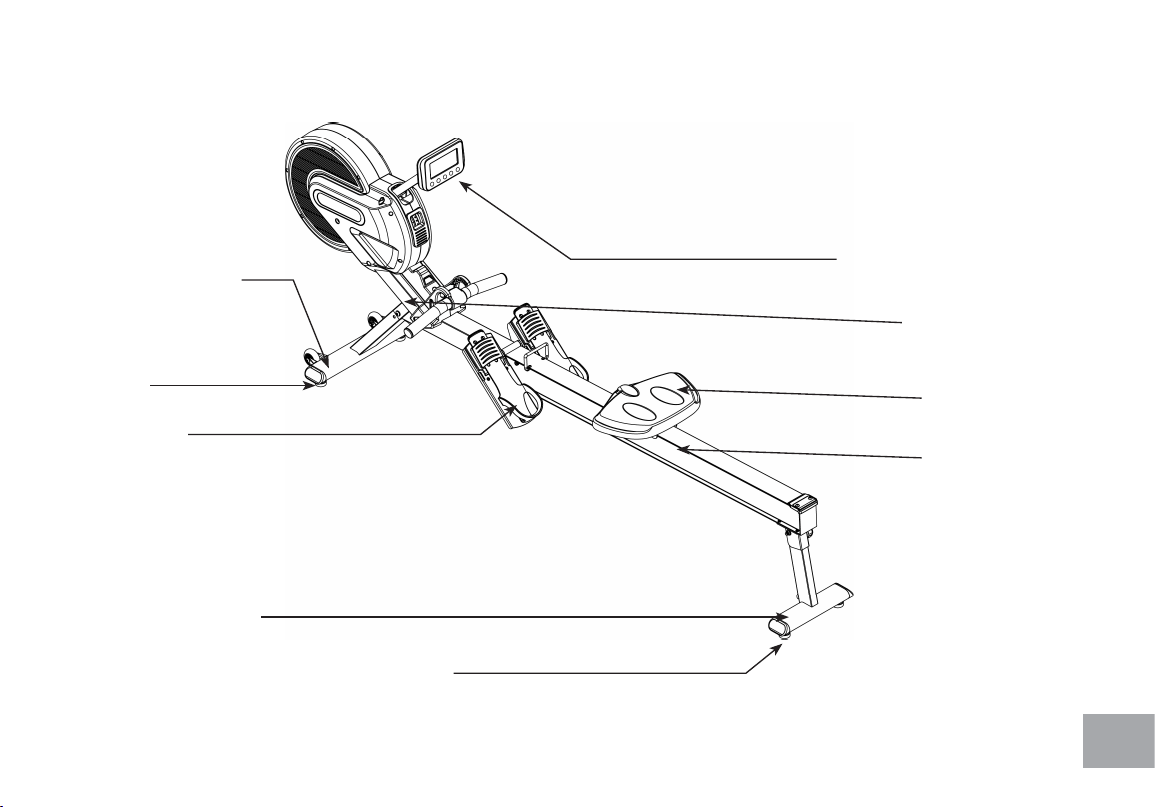
LEVELERS
FOOT PEDALS
LEVELERS
FRONT STABILIZER
REAR STABILIZER
ALUMINUM RAIL
MAIN FRAME
SEAT
CONSOLE
10
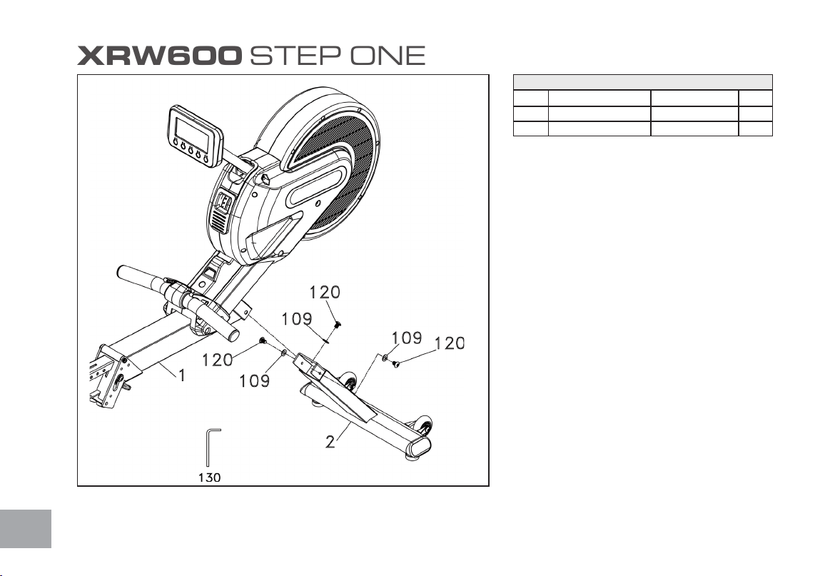
XRW600 STEP ONE
HARDWARE FOR STEP 1
PART TYPE DESCRIPTION QTY
109 FLAT WASHER
3/8”X19X1.5T
3
120 BOLT
3/8”X3/4”
3
1. Gather HARDWARE FOR STEP 1.
2. Use the WRENCH (130) to tighten 3 BUTTON
HEAD SOCKET BOLTS (120) together with
3 FLAT WASHERS (109) to secure the MAIN
FRAME (1) and FRONT STABILIZER (2)
together.
11
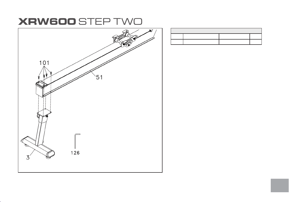
XRW600 STEP TWO
HARDWARE FOR STEP 2
PART TYPE DESCRIPTION QTY
101 BOLT
M6X10mm
4
1. Gather HARDWARE FOR STEP 2.
2. Use ALLEN WRENCH (126) to tighten 4
BUTTON HEAD SOCKET BOLTS (101)
through the ALUMINUM TRACK (51) then
secure the ALUMINUM TRACK (51) and the
REAR STABILIZER (3) together.
12
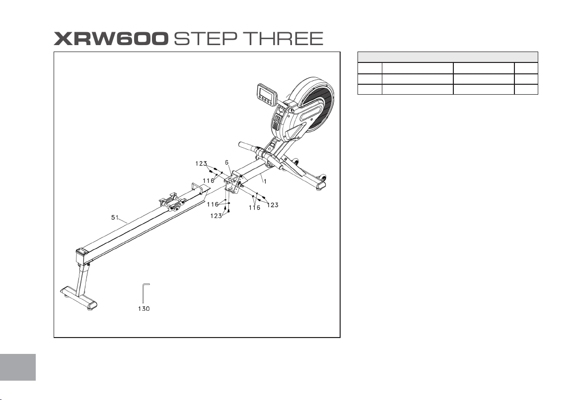
XRW600 STEP THREE
HARDWARE FOR STEP 3
PART TYPE DESCRIPTION QTY
116 SPLIT WASHER
8X1.5T
6
123 BOLT
M8X15mm
6
1. Gather HARDWARE FOR STEP 3.
2. Attach the other end of the ALUMINUM
TRACK (51) to FOLDING END ASSEM-
BLY (6) of the Main Frame (1) and use ALLEN
WRENCH (130) to tighten the 6 SOCKET
HEAD CAP BOLTS (123) together with 6
SPLIT WASHERS (116).
13
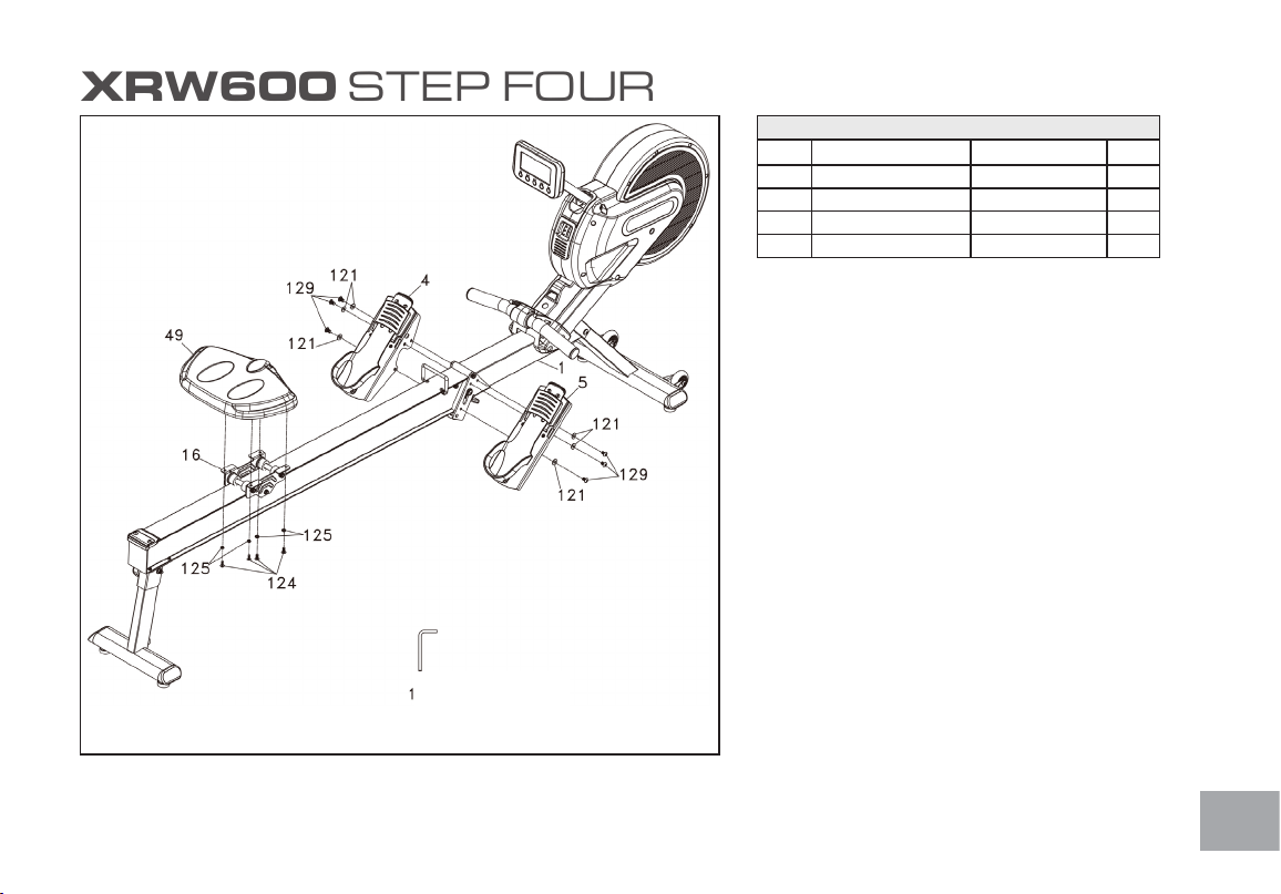
XRW600 STEP FOUR
HARDWARE FOR STEP 4
PART TYPE DESCRIPTION QTY
121 Flat Washer
5/16” x Ø18 x 1.5T
6
124 Phillips Head Screw
M6 x 15L
4
125 Spring Washer
Ø1/4”
4
129 Button Head Socket Bolt
M8 x 12L
6
1. Gather HARDWARE FOR STEP 4.
2. Use Combination M5 ALLEN WRENCH &
PHILLIPS HEAD SCREW DRIVER (127)
to tighten 6 BUTTON HEAD SOCKET
BOLT(129) and 6 FLAT WASHERS(121) to
install then LEFT AND RIGHT PEDALS(4,5)
on the MAIN FRAME(1). Use again
COMBINATION M5 ALLEN WRENCH &
PHILLIPS HEAD SCREW DRIVER (127)
to tighten 4 PHILLIPS HEAD SCREW(124)
together with 4 SPLIT WASHERS(125) to install
SEAT(49) onto the SEAT ATTACHING
BOARD (16).
14
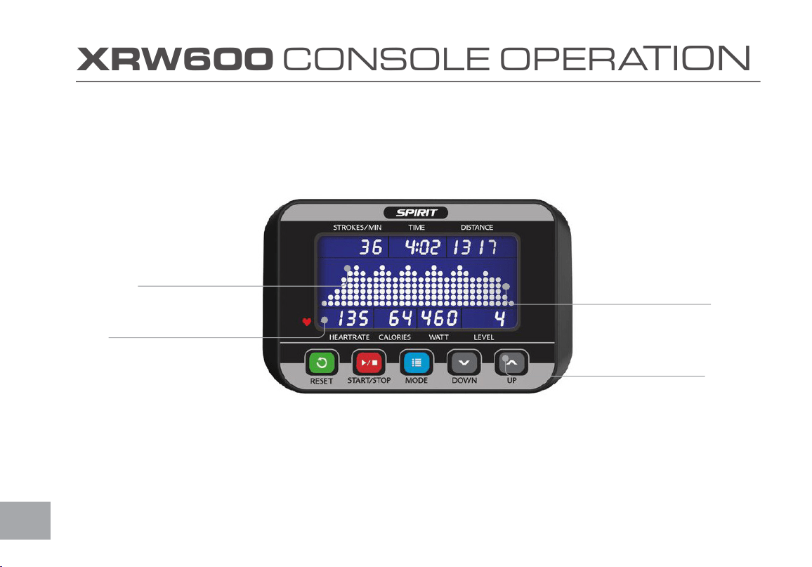
XRW600 CONSOLE OPERATION
Large Blue-LED
Matrix Window
Ten innovative
programs offer a
variety of work-outs
Easy-Touch
Control Buttons
Built-in Heart
Rate Receiver

15
Power
When Pressing any key button wakes up the console which has been turned off, the console LCD will
turn on with full display and beeps for 2 seconds then enters idle mode. When there is speed signal
input with the speed sensor detected, it directly enters Manual workout mode.
Power off: In any mode during turning on, if there is not any button activated or no rowing activity
lasts for 1 minute, it turns off automatically.
Window Functions
Stroke/min
• S/M value shows the equivalent strokes per minute.
Time
• It shows the time.
• Range of time: 00:00~99:59(minute: second)
• The time is accumulated for each workout mode.
• When time is set to count down, it shows the time remaining.
Distance
• The distance range is 0~9999 and switches to the format of 1X.XX when the value is over 9999.
• The distance will be accumulated for each workout mode.
• When the distance is set to count down, it shows the remaining distance.

16
Heart Rate
• The heart rate range is 40~220 bpm
• When the heart rate signal is detected, the small dot at lower right corner of the heart rate window will be blinking to-
gether with heart rate value showing.
• When there is no heart rate signal detected, the heart rate window shows nothing.
Calories
• The calorie window shows the value of calories burned .
• The calorie range is 0~999.
• The calorie value is based on built in estimates of the average user and may not reect accuracy. To have a more accurate
basis of caloric burn - please contact your physician and they can assist you.
Watts
• The Watts window shows Watt value for each stroke.
• The Watt range is 0 ~ 2000.
• When the numbers show over 999 (four digits), the display uses a decimal to show in thousands. E.g. 1000 shows as 1.00,
1240 reads as 1.24, 1250 as 1.25, 2000 as 2.00, etc.
Level
• The level window shows the current resistance level.
• The level range is 1~16
• Level 1 and 2 would light the rst dot, level 3 and 4 would light the second dot, etc.

17
500M/Time
• Only workout modes of Manual, Distance, Time and Calorie are with this display function.
• For Manual workout mode as an example: When the console starts, Matrix in the middle of LCD will show the wave pat-
tern then switch to 500M/TIME 00:00 across center display after 5 seconds then switch again back to the wave pattern
after another 5 seconds and continue to repeat the cycle. This is the function of SCAN.
• The console goes directly into SCAN mode after start. If MODE button is pressed, it shows the wave pattern. Pressing
the MODE button again, it displays 500M/TIME and repeat again by pressing “MODE” button it goes back with “SCAN”
function (recyclable).
Key button Function
• Any valid key button pressed will generate a beep sound.
• When in power off mode, pressing any key button turns on the console.
Mode Key
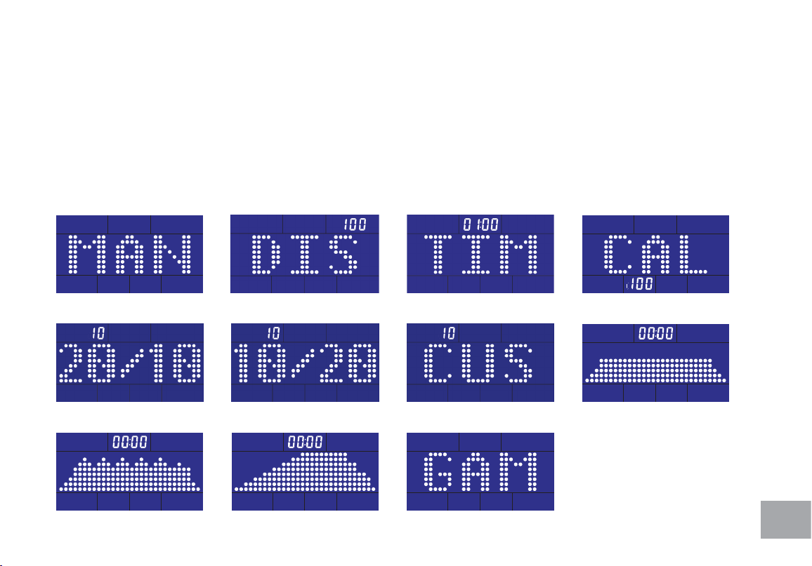
• Under idle mode, pressing MODE key each time switches the workout mode with the following sequence:
• MANUAL » DISTANCE » TIME » CALORIES » 20/10 INTERVAL » 10/20 INTERVAL » CUSTOM INTERVAL »
Fat Burn » Cardio » Strength » Game
• The default workout mode after turning on the unit is Manual mode.
• To choose the target workout mode, when the matrix window shows the desired workout pattern and parameter window
value to be set will be blinking each second.
Up Key
• Under the setting mode of the target workout, the parameter is will be counted up.

18
• The value increases one increment when UP key is pressed once.
Down Key
• Under the setting mode of the target workout, the parameter is will be counted down.
• The value decreases one increment when DOWN key is pressed once.
Start/Stop Key
• Under idle mode, pressing Start/Stop key button enters Manual workout mode.
• To conrm the value the window is showing when setting the parameter under each target workout mode and to start
the workout mode.
• Press to end the current workout mode and all message windows stop counting.
Reset Key
• Pressing this key button under stopping mode, the image switches to the idle mode.
• The reset key button is valid only in stopping mode.
• Under any mode, pressing this key button for 3 seconds turns on the console again.
19
Operating Instruction
The screen is with full display and the buzzer beeps for two seconds after turning on. Pressing Start
button goes directly to Manual workout mode or pressing MODE button to switch and select a
workout mode with the workout sequence shown as below:
MANUAL » DISTANCE » TIME » CALORIES » 20/10 INTERVAL » 10/20 INTERVAL » CUSTOM INTERVAL » Fat
Burn » Cardio » Strength » Game
The program name will scroll from left to right to tell the user what it is.
Manual
20/10 Interval
Cardio
Distance
10/20 Interval
Strength
Time
Custom Interval
Game
Calories
Fat Burn
20
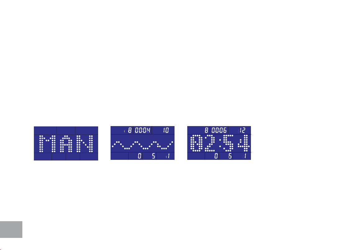
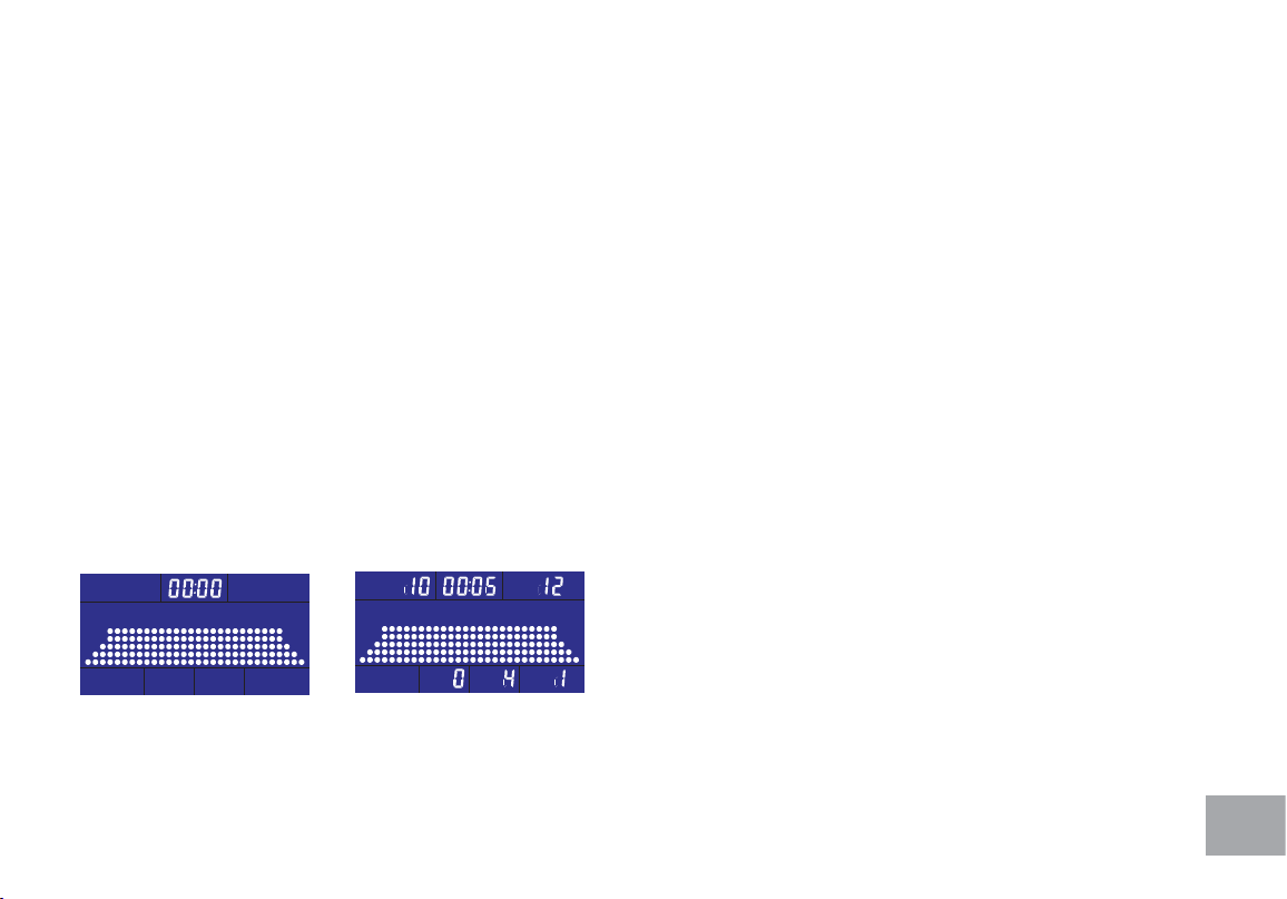
Manual Mode
To choose MANUAL mode (Fig. 1-1)
Pressing Start/Stop button begins the workout mode or pulling the handlebar under the idle mode
enters directly into Manual workout mode.
The image at the center of LCD will scan every 5 seconds to show the stroke speed with wave pattern
(Fig. 1-2) and 500M/TIME (Fig. 1-3) or pressing MODE button to cancel scanning with wave pattern
only. Pressing MODE again switches the image to show 500M/TIME.
Pressing UP or DOWN button and adjusts the resistance level which is shown at bottom right corner
of LEVEL window.
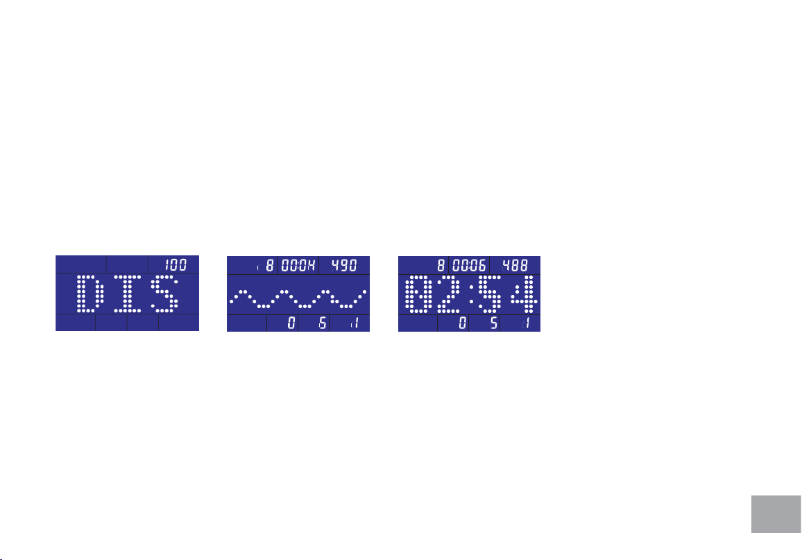
Target Distance
To choose target distance count-down Distance workout mode (Fig. 2-1)
Use UP/DOWN buttons to adjust and set the workout distance. The default distance is 100M with
increment of 50M up or down. Press Start/Stop button to conrm the setting and start the workout
mode.
Fig 1-1 Fig 1-2 Fig 1-3
21
The image at the center of LCD will scan every 5 seconds to show the stroke speed with wave pattern
(Fig. 2-2) and 500M/TIME (Fig. 2-3) or pressing MODE button to cancel scanning with wave pattern
only. Pressing MODE again switches the image to show 500M/TIME.
Distance window counts down from target distance setting value and shows the remaining distance of
the workout.
Under the workout mode, pressing UP or DOWN key button adjusts the resistance level.
When the distance is counted down to 0, the workout completes and the buzzer sounds with a long
beep. If rowing continues, the distance count-down repeats.
Fig 2-1 Fig 2-2 Fig 2-3
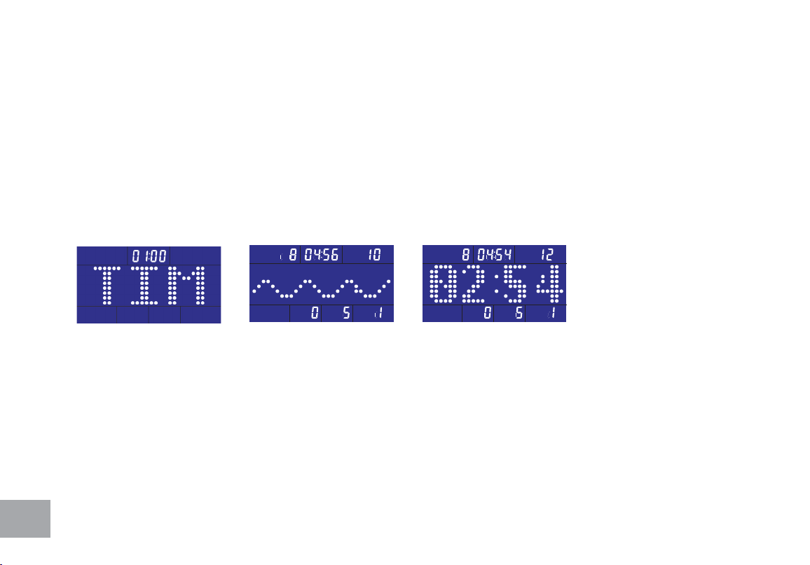
Target Time
To choose target time count-down Time workout mode (Fig. 3-1)
Use UP/DOWN buttons to adjust and set the workout time. The default distance is 1:00 with
1-minute increment of up or down (99:00 maximum). Press Start/Stop button to conrm the setting
and start the workout mode.
22
The image at the center of LCD will scan every 5 seconds to show the stroke speed with wave pattern
(Fig. 3-2) and 500M/TIME (Fig. 3-3) or pressing MODE button to cancel scanning with wave pattern
only. Pressing MODE again switches the image to show 500M/TIME.
Under the workout mode, pressing UP or DOWN key button adjusts the resistance level.
Time window counts down from the setting time value and shows the remaining time of the workout.
When time is counted down to 0:00, the workout completes and the buzzer sounds with a long beep.
If rowing continues, the time count-down repeats.
Fig 3-1 Fig 3-2 Fig 3-3
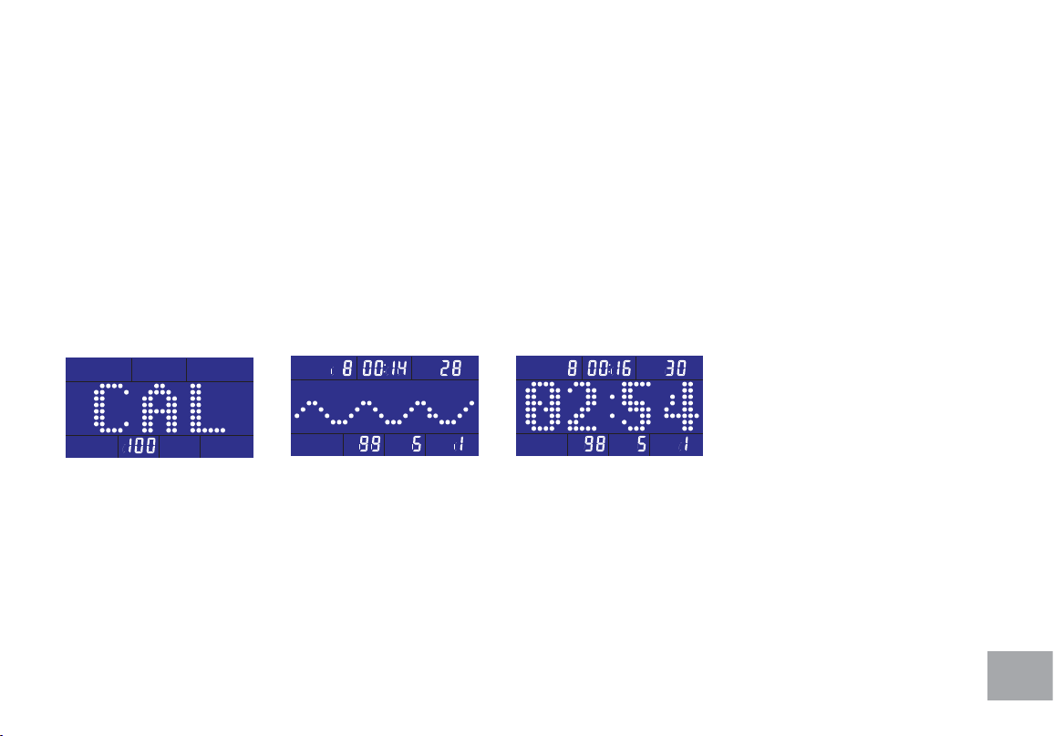
Target Calorie
To choose target calorie count-down Calories workout mode (Fig. 4-1)
Use UP/DOWN buttons to adjust and set the target calorie. The default value is 100 with increment
of 10 up or down. Press Start/Stop button to conrm the setting and start the workout mode.
23
The image at the center of LCD will scan every 5 seconds to show the stroke speed with wave pattern
(Fig. 4-2) and 500M/TIME (Fig. 4-3) or pressing MODE button to cancel scanning with wave pattern
only. Pressing MODE again switches the image to show 500M/TIME.
Calorie window counts down from the setting target calorie value and shows the remaining calorie of
the workout.
Under the workout mode, pressing UP or DOWN key button adjusts the resistance level.
When calorie is counted down to 0, the workout completes and the buzzer sounds with a long beep. If
rowing continues, the time count-down repeats.
Fig 4-1 Fig 4-2 Fig 4-3
24
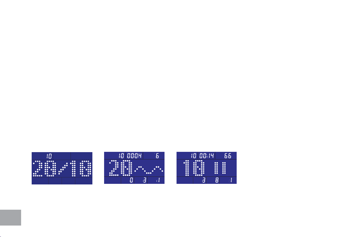
20/10 Interval
To choose 20/10 INTERVAL workout mode (Fig. 5-1)
The image at the center of LCD: 20 seconds (Exercise)/10 seconds (Rest)
Pressing Start/Stop button starts the workout mode.
The image at the center of LCD shows time count-down of current workout and wave (Fig. 5-2) or
rest time count-down and mark (Fig. 5-3).
Under the workout mode, pressing UP or DOWN key button adjusts the resistance level.
There are 10 Exercise/Rest cycles for each workout time.
When workout completes, the buzzer sounds with a long beep. If rowing continues, the time count-
down repeats.
Fig 5-1 Fig 5-2 Fig 5-3

25
10/20 Interval
To choose 10/20 INTERVAL workout mode (Fig. 6-1)
The image at the center of LCD: 10 seconds (Exercise)/20 seconds (Rest)
Pressing Start/Stop button starts the workout mode.
The image at the center of LCD shows time count-down of current workout and wave (Fig. 6-2) or
rest time count-down and mark (Fig. 6-3).
Under the workout mode, pressing UP or DOWN key button adjusts the resistance level.
There are 10 Exercise/Rest cycles for each workout time.
When workout completes, the buzzer sounds with a long beep. If rowing continues, the time count-
down repeats.
Fig 6-1 Fig 6-2 Fig 6-3
26
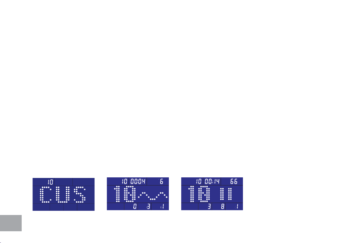
Custom Interval
To choose CUSTOM INTERVAL workout mode (Fig. 7-1)
User-dene time (Exercise)/time (Rest): the default is 10 seconds (Exercise)/10 seconds (Rest)
The value at left side of the matrix window ashes for setting the exercise time. Use UP/DOWN
buttons to adjust and set the workout time. The default time is 10 seconds with 1-second increment of
up or down. Press Start/Stop button to conrm the setting and start the workout mode.
The value at right side of the matrix window ashes for setting the rest time. Use UP/DOWN buttons
to adjust and set the workout time. The default time is 10 seconds with 1-second increment of up or
down. Press Start/Stop button to conrm the setting and start the workout mode.
The image at the center of LCD: 10 seconds (Exercise)/10 seconds (Rest)
Pressing Start/Stop button starts the workout mode.
The image at the center of LCD shows time count-down of current workout and wave (Fig. 7-2) or
rest time count-down and mark (Fig. 7-3).
Fig 7-1 Fig 7-2 Fig 7-3
27
Under the workout mode, pressing UP or DOWN key button adjusts the resistance level.
There are 10 Exercise/Rest cycles for each workout time.
When workout completes, the buzzer sounds with a long beep. If rowing continues, the time count-
down repeats.
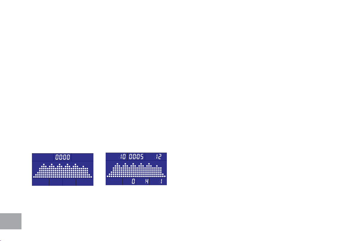
Fat Burn
To choose Fat Burn workout mode (Fig. 8-1)
Pressing Start/Stop button and begins the workout mode or setting the workout time. Use UP/
DOWN buttons to adjust the time. The increment of adjustment is 5-minute (99:00 maximum). Press
Start/Stop button to start the workout mode.
The image at the center of LCD shows the fat burn prole (Fig. 8-2)
Fig 8-1 Fig 8-2
28
Under the workout mode, pressing UP or DOWN key button adjusts the resistance level.
Time window starts count-down from the setting time and shows the remaining workout time.
When time is counted down to 0:00, the workout completes and the buzzer sounds with a long beep.
If rowing continues, the time count-down repeats.
Cardio Workout
To choose cardio workout mode (Fig. 9-1)
Pressing Start/Stop button and begins the workout mode or setting the workout time. Use UP/
DOWN buttons to adjust the time. The increment of adjustment is 5-minute (99:00 maximum). Press
Start/Stop button to start the workout mode.
The image at the center of LCD shows the cardio prole (Fig. 9-2)
Fig 9-1 Fig 9-2
29
Under the workout mode, pressing UP or DOWN key button adjusts the resistance level.
Time window starts count-down from the setting time and shows the remaining workout time.
When time is counted down to 0:00, the workout completes and the buzzer sounds with a long beep.
If rowing continues, the time count-down repeats.
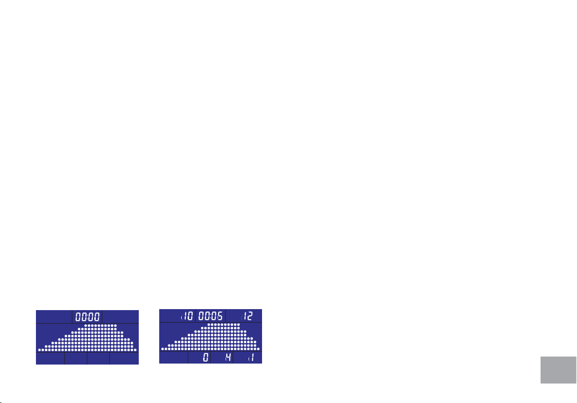
Strength Workout
To choose Strength workout mode (Fig. 10-1)
Pressing Start/Stop button and begins the workout mode or setting the workout time. Use UP/
DOWN buttons to adjust the time. The increment of adjustment is 5-minute (99:00 maximum). Press
Start/Stop button to start the workout mode.
The image at the center of LCD shows the strength prole (Fig. 10-2)
Time window starts count-down from the setting time and shows the remaining workout time.
When time is counted down to 0:00, the workout completes and the buzzer sounds with a long beep.
If rowing continues, the time count-down repeats.
Fig 10-1 Fig 10-2
30
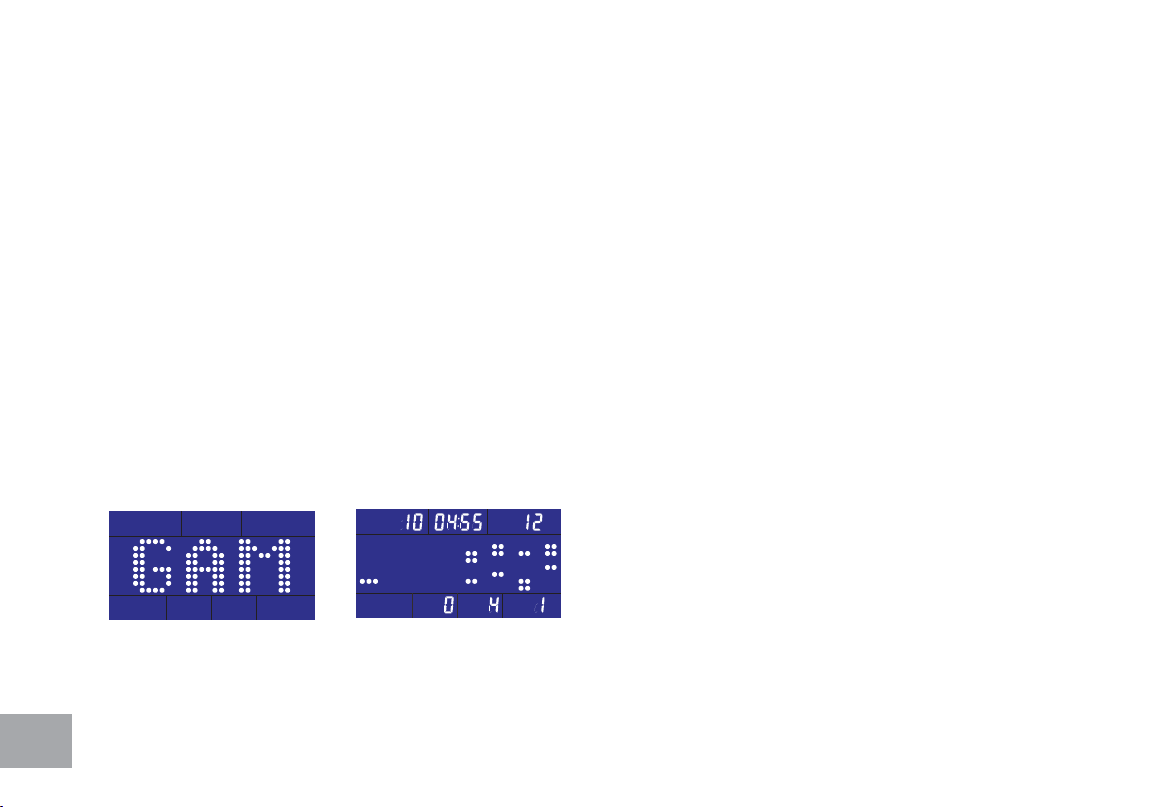
Game Workout
To choose GAME workout mode (Fig. 11-1)
Pressing Start/Stop button and begins the GAME workout mode (11-2).
The goal of the Game Workout Mode is the manuveur your user dots through an obstacle eld by
rowing faster or slower to raise/lower the use dot sprite.
Three dots at left side represents the user position and the image shift one prole left per second and
continue to scroll.
The position of the user will not shift. However, the faster the user rows, the higher the user’s position.
When there is no input, the position of the user goes down to the lowest. The height of the user’s
position is equivalent to the speed the user strokes.
The time for the game workout starts counting down from 5 minutes and ends when time is up.
Fig 11-1 Fig 11-2
31
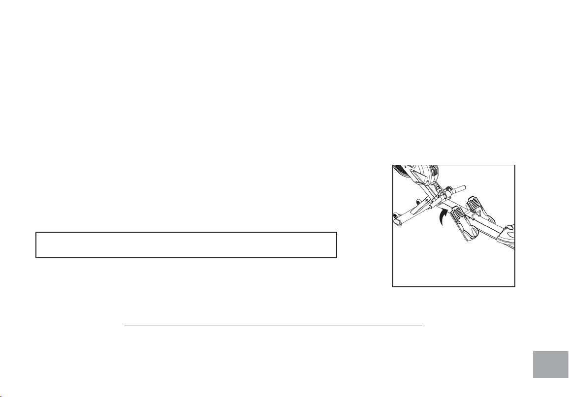
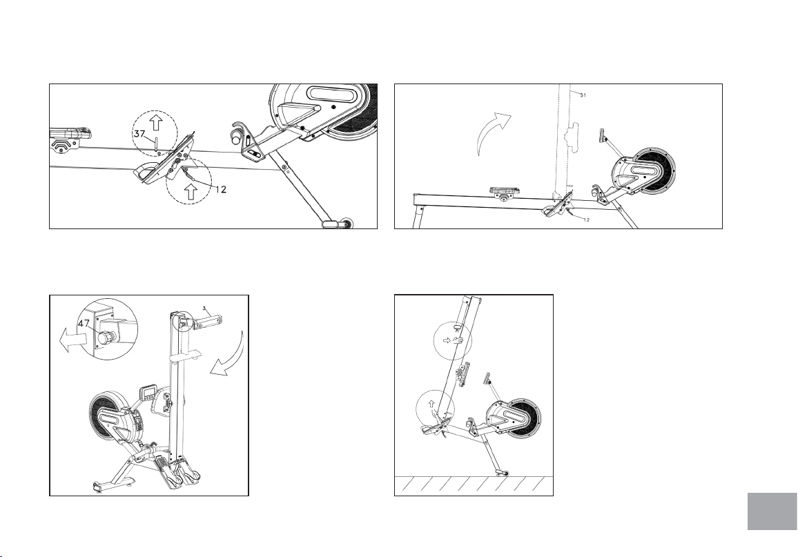
Folding/Unfolding Procedures
Moving Procedures
1. Hold the Handlebar (37) to lift the rower slightly and
press the Release Lever (12).
2. Lift and fold the Aluminum Track until it locks into place.
3. To fold Rear
Stabilizer, turn
Knob (47)
counterclockwise
until loosened.
Pull Knob to
release and fold
Rear Stabilizer.
4. To unfold Rower,
reverse steps.
1. Fold the aluminum rail
assembly up.
2. Lift the rear and roll
away.
32
Heart Rate Monitoring (chest strap not included)
The old motto, “no pain, no gain”, is a myth that has been overpowered by the benets of exercising
comfortably. A great deal of this success has been promoted by the use of heart rate monitors. With
the proper use of a heart rate monitor, many people nd that their usual choice of exercise intensity
was either too high or too low and exercise is much more enjoyable by maintaining their heart rate in
the desired benet range.
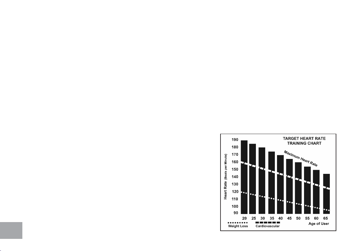
To determine the benet range in which you wish to train, you must rst determine your Maximum
Heart Rate. This can be accomplished by using the following formula: 220 minus your age. This will give
you the Maximum Heart Rate (MHR)for someone of your age. To determine the effective heart rate
range for specic goals you simply calculate a percentage of your MHR. Your Heart rate training zone is
50% to 90% of your maximum heart rate. 60% of your MHR is the recommended for burning fat while
80% is recommended for strengthening the cardio vascular
system. This 60% to 80% is the zone to stay in for maximum
benet.
For someone who is 40 years old their
target heart rate zone is calculated:
220 – 40 = 180 (maximum heart rate)
180 x .6 = 108 beats per minute (60% of maximum)
180 X .8 = 144 beats per minute (80% of maximum)
So for a 40 year old the training zone would
be 108 to 144 beats per minute.

33
The two most popular reasons for, or goals, of exercise are cardiovascular tness (training for the heart
and lungs) and weight control. The black columns on the chart above represent the MHR for a person
whose age is listed at the bottom of each column. The training heart rate, for either cardiovascular
tness or weight loss, is represented by two different lines that cut diagonally through the chart. A
denition of the lines’ goal is in the bottom left-hand corner of the chart. If your goal is cardiovascular
tness or if it is weight loss, it can be achieved by training at 80% or 60%, respectively, of your MHR
on a schedule approved by your physician. Consult your physician before participating in any exercise
program.

34
Rate of Perceived Exertion
Heart rate is important but listening to your body also has a lot of advantages. There are more
variables involved in how hard you should workout than just heart rate. Your stress level, physical health,
emotional health, temperature, humidity, the time of day, the last time you ate and what you ate, all
contribute to the intensity at which you should workout. If you listen to your body, it will tell you all of
these things.
The rate of perceived exertion (RPE), also know as the Borg scale, was developed by Swedish
physiologist G.A.V. Borg. This scale rates exercise intensity from 6 to 20 depending upon how you feel
or the perception of your effort.
The scale is as follows:
Rating Perception of Effort
6 Minimal
7 Very, very light
8 Very, very light +
9 Very light
10 Very light +
11 Fairly light
12 Comfortable
13 Somewhat hard
14 Somewhat hard +
15 Hard
16 Hard +
17 Very hard
18 Very hard +
19 Very, very hard
20 Maximal
You can get an approximate heart rate level for each rating by simply adding a zero to each rating. For example a
rating of 12 will result in an approximate heart rate of 120 beats per minute. Your RPE will vary depending up the
factors discussed earlier. That is the major benet of this type of training. If your body is strong and rested, you will feel
strong and your pace will feel easier. When your body is in this condition, you are able to train harder and the RPE will
support this. If you are feeling tired and sluggish, it is because your body needs a break. In this condition, your pace will
feel harder. Again, this will show up in your RPE and you will train at the proper level for that day.
35
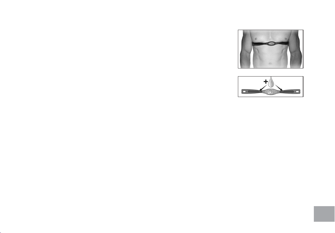
Wearing The Chest Strap
1. Attach the transmitter to the elastic strap using the interlocking key.
2. Adjust the strap as tightly as possible as long as the strap is not too tight to remain
comfortable.
3. Position the transmitter with the logo centered in the middle of your torso facing away
from your chest (some people must position the transmitter slightly left of center). Attach
the nal end of the elastic strap by inserting the round end and, using the locking parts,
secure the transmitter and strap around your chest.
4. Position the transmitter directly below the pectoral muscles.
5. Sweat is the best conductor to measure very minute heart beat electrical signals. However,
plain water can also be used to pre-wet the electrodes (2 ribbed oval areas on the reverse
side of the belt and both sides of the transmitter). It’s also recommended that you wear
the transmitter strap a few minutes before your work out. Some users, because of body chemistry, have a more difcult
time in achieving a strong, steady signal at the beginning. After “warming up”, this problem lessens.
6. Your workout must be within range - distance between transmitter/receiver – to achieve a strong steady signal. The
length of range may vary somewhat but generally stay close enough to the console to maintain good, strong, reliable
readings. Wearing the transmitter directly on bare skin assures you of proper operation. If you wish, you may wear the
transmitter over a shirt. To do so, wet the areas of the shirt that the electrodes will rest upon.
Note: The transmitter is automatically activated when it detects activity from the user’s heart. Additionally, it automatically
deactivates when it does not receive any activity. Although the transmitter is water resistant, moisture can have the effect of
creating false signals, so you should take precautions to completely dry the transmitter after use to prolong battery life (estimated
transmitter battery life is 2500 hours). The replacement battery is Panasonic CR2032.
*Not Included

36
Erratic Operation
Caution! Do not use this Rower for Heart Rate monitoring unless a steady, solid Actual Heart Rate
value is being displayed. High, wild, random numbers being displayed indicate a problem.
Areas to look for interference which may cause erratic heart rate:
1. Microwave ovens, TV’s, small appliances, etc.
2. Fluorescent lights.
3. Some household security systems.
4. Perimeter fence for a pet.
5. Some people have problems with the transmitter picking up a signal from their skin. If you have problems try wearing
the transmitter upside down. Normally the transmitter will be oriented so the Spirit Fitness logo is right side up.
6. The antenna that picks up your heart rate is very sensitive. If there is an outside noise source,
turning the whole machine 90 degrees may de-tune the interference.
7. Another Individual wearing a transmitter within 3’ of your machine’s console.
If you continue to experience problems contact your dealer.

37
GENERAL MAINTENANCE
1. Wipe down all areas in the sweat path with a damp cloth after each workout.
2. If a squeak, thump, clicking or rough feeling develops the main cause is most likely one of three reasons:
I. The hardware was not sufciently tightened during assembly. All bolts that were installed during assembly need to
be tightened as much as possible. It may be necessary to use a larger wrench than the one provided if you cannot
tighten the bolts sufciently. I cannot stress this point enough; 90% of calls to the service department for noise
issues can be traced to loose hardware.
II. The crank arm nut needs to be retightened.
III. If squeaks or other noises persist, check that the unit is properly leveled. There are 2 leveling pads on the bottom
of the rear stabilizer, use a 14mm wrench (or adjustable wrench) to adjust the levelers.

38
Rower Warranty - Effective August 22, 2018
Spirit Fitness, Inc. (Spirit Fitness) warrants all its Rower parts for a period of time listed below from the date of retail sale, as determined by sale receipt,
or in the absence of a sales receipt eighteen (18) months from the original factory shipping date. Spirit Fitness’ responsibilities include providing new or
remanufactured parts, at Spirit Fitness’ option, and technical support to our independent dealers and servicing organizations. In the absence of a dealer or
service organization, these warranties will be administered by Spirit Fitness directly to a consumer. The warranty period applies to the
following components:
NORMAL RESPONSIBILITIES OF THE CONSUMER
This warranty applies only to products in ordinary household or Light Commercial use (see restrictions above), and the consumer/facility is responsible for
the items listed below:
1. The warranty registration card must be completed and returned to the address listed on the card within 10 days of the original purchase to validate
the manufacturer’s limited warranty.
2. Proper use of the Rower in accordance with the instructions provided in this manual
3. Proper installation in accordance with instructions provided with the Rower and with all local electric codes.
4. Expenses for making the Rower accessible for servicing, including any item that was not part of the Rower at the time it was shipped from the
factory.
5. Damages to the Rower nish during shipping, installation or following installation.
6. Routine maintenance of this unit as specied in this manual.
EXCLUSIONS
This warranty does not cover the following:
1. CONSEQUENTIAL, COLLATERAL, OR INCIDENTAL DAMAGES SUCH AS PROPERTY DAMAGE AND INCIDENTAL EXPENSES
RESULTING FROM ANY BREACH OF THIS WRITTEN OR ANY IMPLIED WARRANTY.
Note: Some states do not allow the exclusion or limitation of incidental or consequential damages, so this limitation or exclusion may not apply to
you.
2. Service call reimbursement to the consumer. Service call reimbursement to the dealer that does not involve malfunction or defects in workmanship
or material, for units that are beyond the warranty period, for units that are beyond the service call reimbursement period, for Rower not requiring
component replacement, or Rower not in ordinary household or light commercial use.
3. Damages caused by services performed by persons other than authorized Spirit Fitness service companies; use of parts other than original Spirit
Fitness parts; or external causes such as corrosion, discoloration of paint or plastic, alterations, modications, abuse, misuse, accident, improper mainte-
nance, inadequate power supply, or acts of God.
4. Products with original serial numbers that have been removed or altered.
Warranty
Residential
Frame
Lifetime
Brake
Lifetime
Parts
10 Years
Labor
1 Year

39
5. Products that have been: sold, transferred, bartered, or given to a third party.
6. Products that do not have a warranty registration card on le at Spirit Fitness. Spirit Fitness reserves the right to request proof of
purchase if no warranty record exists for the product.
7. THIS WARRANTY IS EXPRESSLY IN LIEU OF ALL OTHER WARRANTIES EXPRESSED OR IMPLIED, INCLUDING THE WARRANTIES OF
MERCHANTABILITY AND/OR FITNESS FOR A PARTICULAR PURPOSE.
8. Product use in any environment other than a residential setting or non-dues paying facility with 5 hours use or less per day.
9. Warranties outside of the United States may vary. Please contact your local dealer for details.
SERVICE
Keep your bill of sale. Twelve (12) months from the date on the bill of sale or eighteen (18) months from the date of factory shipping as
determined by the serial number establishes the labor warranty period should service be required. If service is performed, it is in your best
interest to obtain and keep all receipts. This written warranty gives you specic legal rights. You may also have other rights that vary from
state to state. Service under this warranty must be obtained by following these steps, in order:
1. Contact your selling authorized Spirit Fitness dealer. OR
2. Contact your local authorized Spirit Fitness service organization.
3. If there is a question as to where to obtain service, contact our service department at (870) 935-1107.
4. Spirit Fitness’ obligation under this warranty is limited to repairing or replacing, at Spirit Fitness’ option, the product through one of our authorized
service centers. All repairs must be preauthorized by Spirit Fitness. If the product is shipped to a service center freight charges to and from the
service
center will be the customer’s responsibility. For replacement parts shipped while the product is under warranty, the customer will be
responsible for shipping and handling charges. For in-home service, the customer will be responsible for a trip charge. There will be an
additional trip charge if the customer is located over 100 miles from the nearest service center.
5. The owner is responsible for adequate packaging upon return to Spirit Fitness. Spirit Fitness is not responsible for damages in shipping. Make all freight
damage claims with the appropriate freight carrier. DO NOT SHIP ANY UNIT TO OUR FACTORY WITHOUT A RETURN AUTHORIZATION
NUMBER. All units arriving without a return authorization number will be refused.
6. For any further information, or to contact our service department by mail, send your correspondence to:
Spirit Fitness, Inc.
P.O. Box 2037
Jonesboro, AR 72402-2037
Product features or specications as described or illustrated are subject to change without notice. All warranties are made by Spirit Fitness, Inc. This
warranty applies only in the 48 contiguous United States. NOTE: This does not apply to Alaska or Hawaii.

800.258.4555
spiritservice@spirittness.com
www.spirittness.com
Spirit Fitness
3000 Nestle Road
Jonesboro, AR 72401
XRW600 Owners Manual
© 2018 All Rights Reserved
Revision 5: 08.22.2018