MAGNETIC ROWING MACHINE
USER MANUAL
IMPORTANT! Please retain owner’s manual for maintenance and adjustment instructions. Your
satisfaction is very important to us.

1
IMPORTANT SAFETY INFORMATION
We thank you for choosing our product. To ensure your safety and health, please use this
equipment correctly. It is important to read this entire manual before assembling and using the
equipment. Safe and effective use can only be achieved if the equipment is assembled, maintained,
and used properly. It is your responsibility to ensure that all users of the equipment are informed of
all warnings and precautions.
1. Before starting any exercise program, you should consult your physician to determine if you
have any medical or physical conditions that could put your health and safety at risk or prevent
you from using the equipment properly. Your physician’s advice is essential if you are taking
medication that affects your heart rate, blood pressure, or cholesterol level.
2. Be aware of your body’s signals. Incorrect or excessive exercise can damage your health. Stop
exercising if you experience any of the following symptoms: pain, tightness in your chest,
irregular heartbeat, shortness of breath, lightheadedness, dizziness, or feelings if nausea. If you
do experience any of these conditions, you should consult your physician before continuing with
your exercise program.
3. Keep children and pets away from the equipment. The equipment is designed for adult use only.
4. Use the equipment on a solid, flat level surface with a protective cover for your floor or carpet.
To ensure safety, the equipment should have at least 2 feet (60 CM) of free space all around it.
5. Ensure that all nuts and bolts are securely tightened before using the equipment. The safety of
the equipment can only be maintained if it is regularly examined for damage and/or wear and
tear.
6. Always use the equipment as indicated. If you find any defective components while assembling
or checking the equipment, or if you hear any unusual noises coming from the equipment during
exercise, discontinue use of the equipment immediately and do not use until the problem has
been rectified.
7. Wear suitable clothing while using the equipment. Avoid wearing loose clothing that may
become entangled in the equipment.
8. Do not place fingers or objects into the moving parts of the equipment.
9. The maximum weight capacity of this unit is 285 pounds (150 KG).
10. The equipment is not suitable for therapeutic use.
11. To avoid bodily injury and/or damage to the product or property, proper lifting and moving are
required.
12. Your product is intended for use in cool and dry conditions. You should avoid storage in extreme
cold, hot or damp areas as this may lead to corrosion and other related problems.
13. This equipment is designed for indoor and home use only; it is not intended for commercial use
2
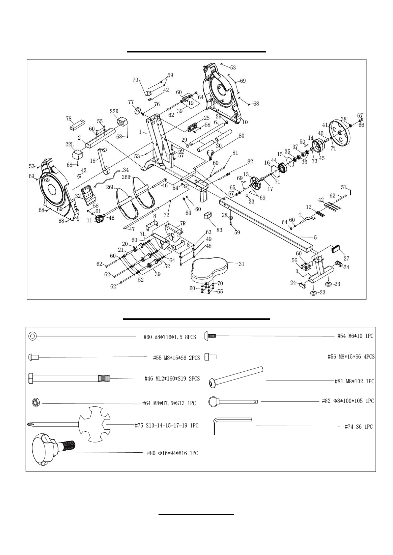
EXPLODED DIAGRAM
HARDWARE PACKAGE
PARTS LIST

3
No. Description Spec. QTY No. Description Spec. QTY
1 Main Frame 1 34 Sensor Wire L370 1
2 Front Stabilizer 1 35
Bearing
Φ35*Φ10*11 1
3 Rear Support 1 36
Bearing
Φ30*Φ17*7 2
4 Magnet Frame 1 37 Bearing 35*17*16 1
5 Sliding Rail 1 38 Bearing Φ26*Φ10*8 1
6 Handlebar 1 39
Bearing
Φ22*Φ8*7 8
7L/R
Seat Supporting
L/R
2 40
Bearing Steel
Φ17*46 1
8 U Shape Bracket 2 41 Inertial Wheel Φ240*25 2.5kg 1
9 Chain Cover L 1 42 Magnet 25*10*5 2800 7
10 Chain Cover R 1 43
Inductor Seat
1
11
Tension Control
Knob
L=210 1 44 Volute Spring t0.5*22*5080 1
12
Plastic Lattice
Magnet
27*7 1 45 Axle Sleeve Φ42*44.5 1
13
Volute Spring
Cover
118.5*11.8 1
46 Bolt
M12*160*S19 2
14 Mesh Belt Wheel Φ35*110 1 47 Fixing Axle for Pedal Φ12*440 1
15 Outer PC Board Φ89*Φ16.5*0.5 1 48 Adjusting Screw M6 L45 2
16
PC Board
Φ111*Φ16*0.5 1 49
U Shape Baffle
30*10*1.5 2 2
17
Axle for Mesh Belt
Wheel
Φ22*133 1 50
Fixing Axle for Mesh
Belt
Φ5*43 1
18 Mesh Belt t1.5*22*2150 1 51 Spring Φ0.8*Φ8*60 65MN 1
19 Mesh Belt Pulley POM Φ42*Φ22*32 1 52 Spacer D8*Φ15*4 6
20 Wheel Φ40*92 POM 3 53 Screw M5*8 3
21
Casing Pipe for
Idler Wheel
Φ13*Φ8*78 ABS 3 54 Screw M6*10 1
22L/R End Cap
30*60 2 55
Screw
M8*15*S6 12
23
Foot Leveler
M8 2 56 Screw M8*15*S6 4
24 End Cap 70*30 2 57 Nut M6 1
25 Handlebar Seat 104*50*18 PVC 1 58 Screw M5*15 3
26L/R Pedal L/R 320*140*55 2 59 Screw M6*20 2
27 End Cap 40*80*1.5 1 60 Washer d8*Φ16 *1.5 24
28
Rubber Buffer
Φ25.2*Φ22*15 1 61
Washer
Φ20*Φ5*1.0 1
29 End Cap Φ25*1.5 PVC
2
62 Bolt M8*125*15 *S14 A 5
30 Foam Grip 180 2 63 Nut M6*H6*S10 2
31 Seat 1 64 Nut M8*H7.5*S13 5
32 Computer 1 65 Nut M10*1.0 H5 1
33 Magnet Φ11*3 1 66 Nut M10*1.0 H3 1

4
No. Description Spec. QTY No. Description Spec. QTY
67 Nut M10*1*H8*S14 2 76 Nut M8 1
68 Screw ST4.2*20*Φ8 6 77
Foot Leveler M8*35 PVC 1
69 Screw ST4.2*16*Φ8 10 78
Shipping Tube
1
70 Spring Washer Φ8 4 79
Connecting
Board
1
71 Wave Washer d10*Φ15*0.3 2 80 Knob PP+Q235 1
72
C-clip
d12 1 81
Bolt
M8*102 1
73 C-clip d36 1 82 Pull Pin ф8*100*105 1
74 Allen Wrench S6 1 83 End cap 1
75 Spanner S13-14-15-17-19 1
5
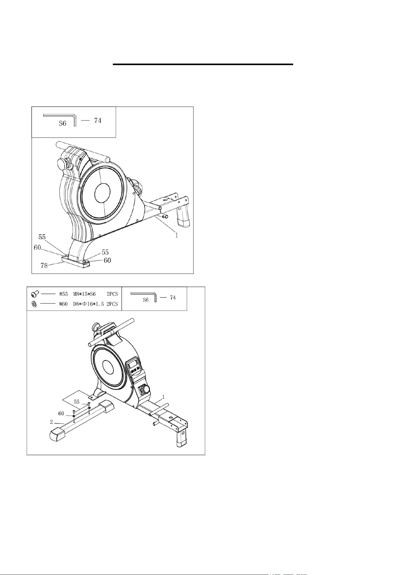
ASSEMBLY INSTRUCTIONS
STEP 2:
Attach Front Stabilizer (No. 2) to Main
Frame (No. 1) using 2 Screws (No. 55) and
2 Washers (No. 60). Tighten and secure
with Allen Wrench (No. 74).
STEP 1:
Remove 2 Screws (No. 55) from Main
Frame (No. 1) with Allen Wrench (No. 74),
then remove 2 Washers (No. 60) and
Shipping Tube (No. 78).
NOTE: Don’t discard 2 Screws (No. 55) and
2 Washers (No. 60), because in Step 2, you
need to use them again.
You may discard Shipping Tube (No. 78) or
save it in case you would like to repackage
the item in the future.
6
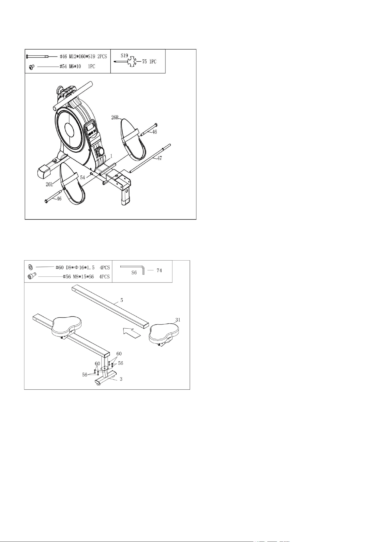
STEP 3:
Attach Fixing Axle for Pedal (No. 47) into
the bottom hole of Main Frame (No. 1)
using 1 Screw (No. 54). Secure and
tighten with Spanner (No. 75).
Attach 2 Bolts (No. 46) into the upper hole
of Main Frame (No. 1) through Pedals
(No. 26L/R). Secure and tighten with
Spanner (No. 75).
NOTE: The Fixing Axle for Pedal (No.
47) should be attached into the middle
position of Main Frame (No. 1).
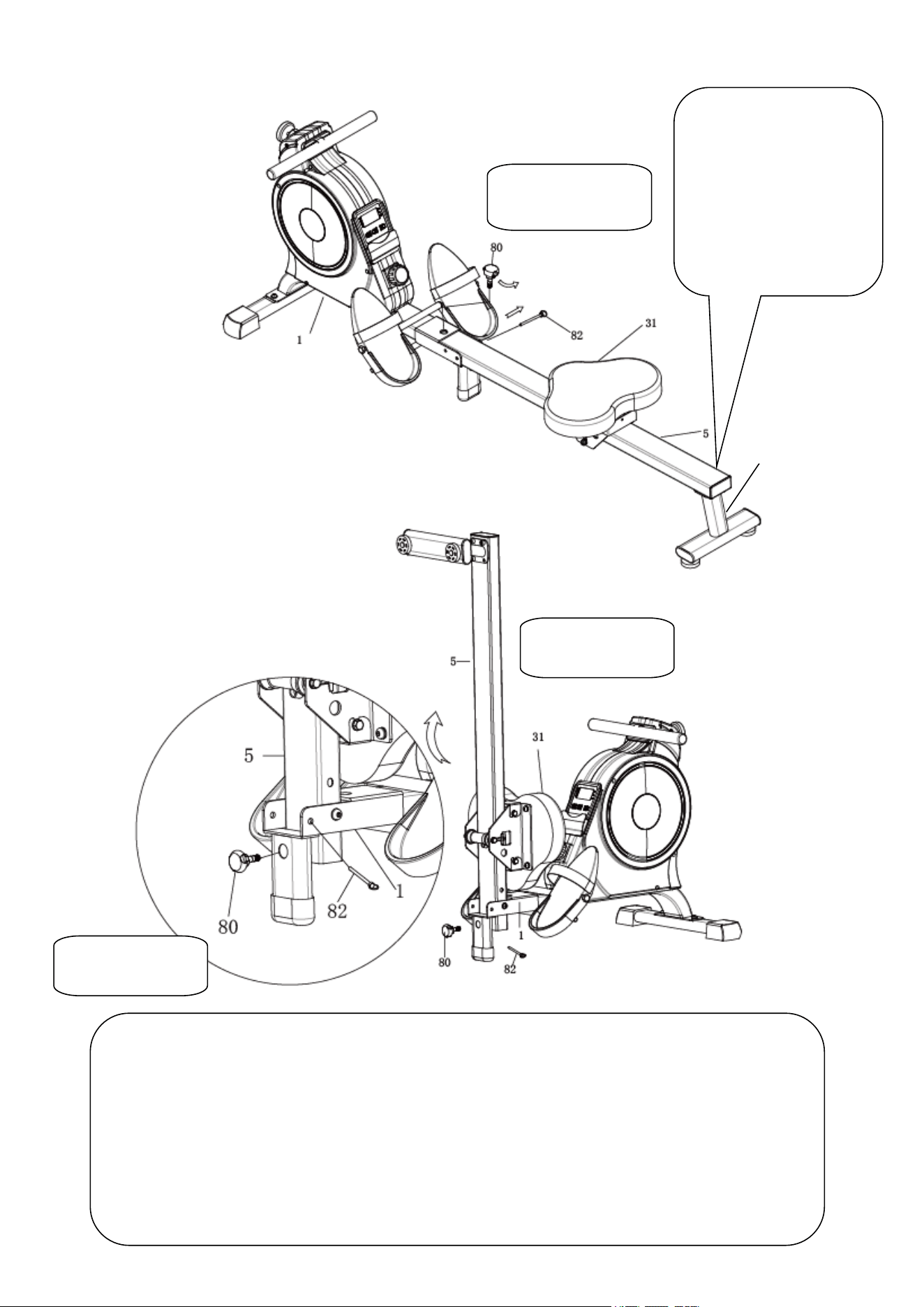
STEP 4:
Insert the Seat (No. 31) into the Sliding
Rail (No. 5).
Attach the Sliding Rail (No. 5) onto the
Rear Support (No. 3) using 4 Screws
(No. 56) and 4 Washers (No. 60). Tighten
and secure with Allen Wrench (No. 74).
7
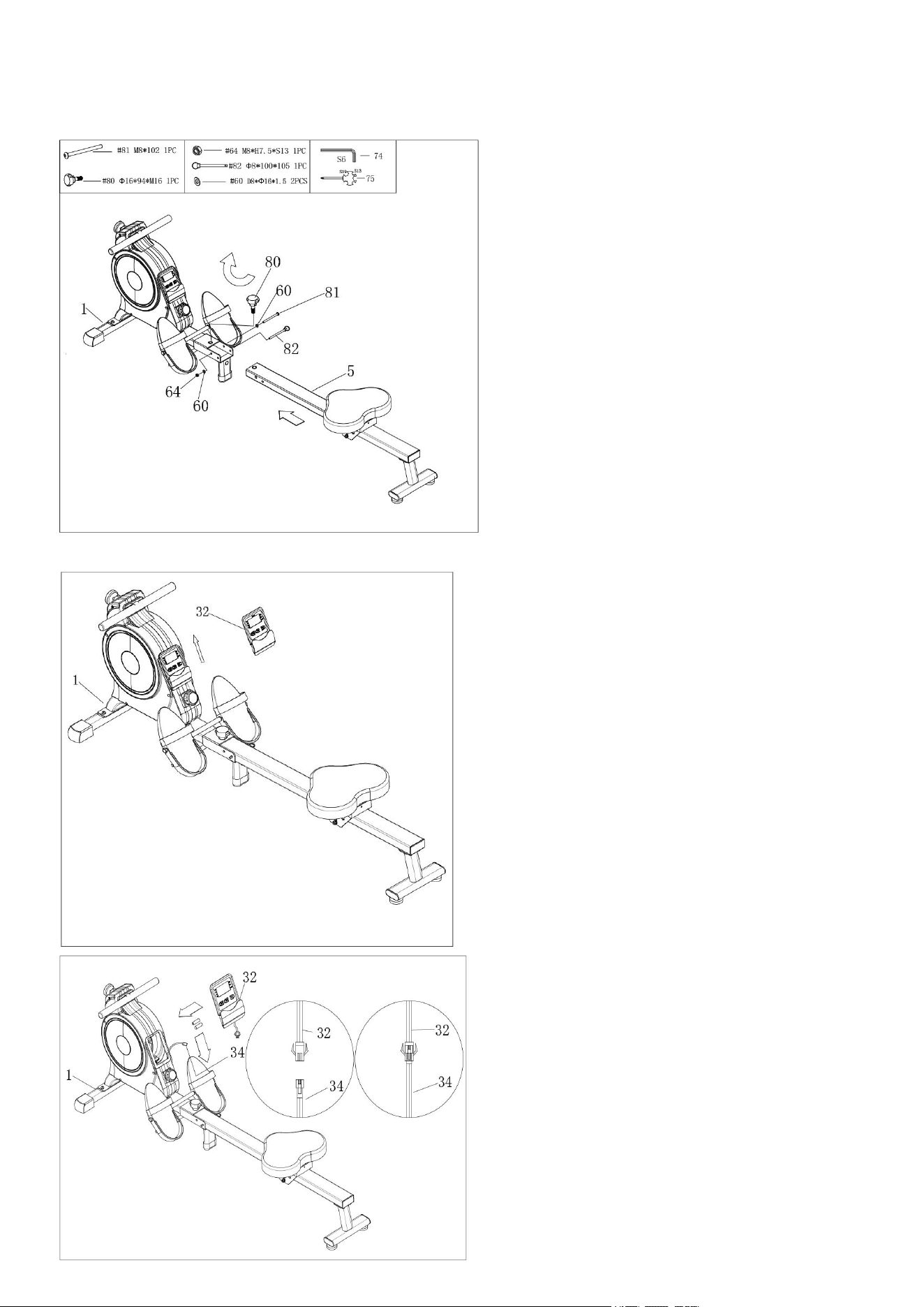
STEP 5:
Attach the Sliding Rail (No. 5) to Main
Frame (No. 1) using Bolt (No. 81), 2
Washers (No. 60), and Nut (No. 64).
Tighten and secure with Spanner (No. 75)
and Allen Wrench (No. 74).
Next, attach the top of the Sliding Rail
(No. 5) to the Main Frame (No1), insert the
Pull Pin (No. 82), then use Knob (No. 80)
to tighten.
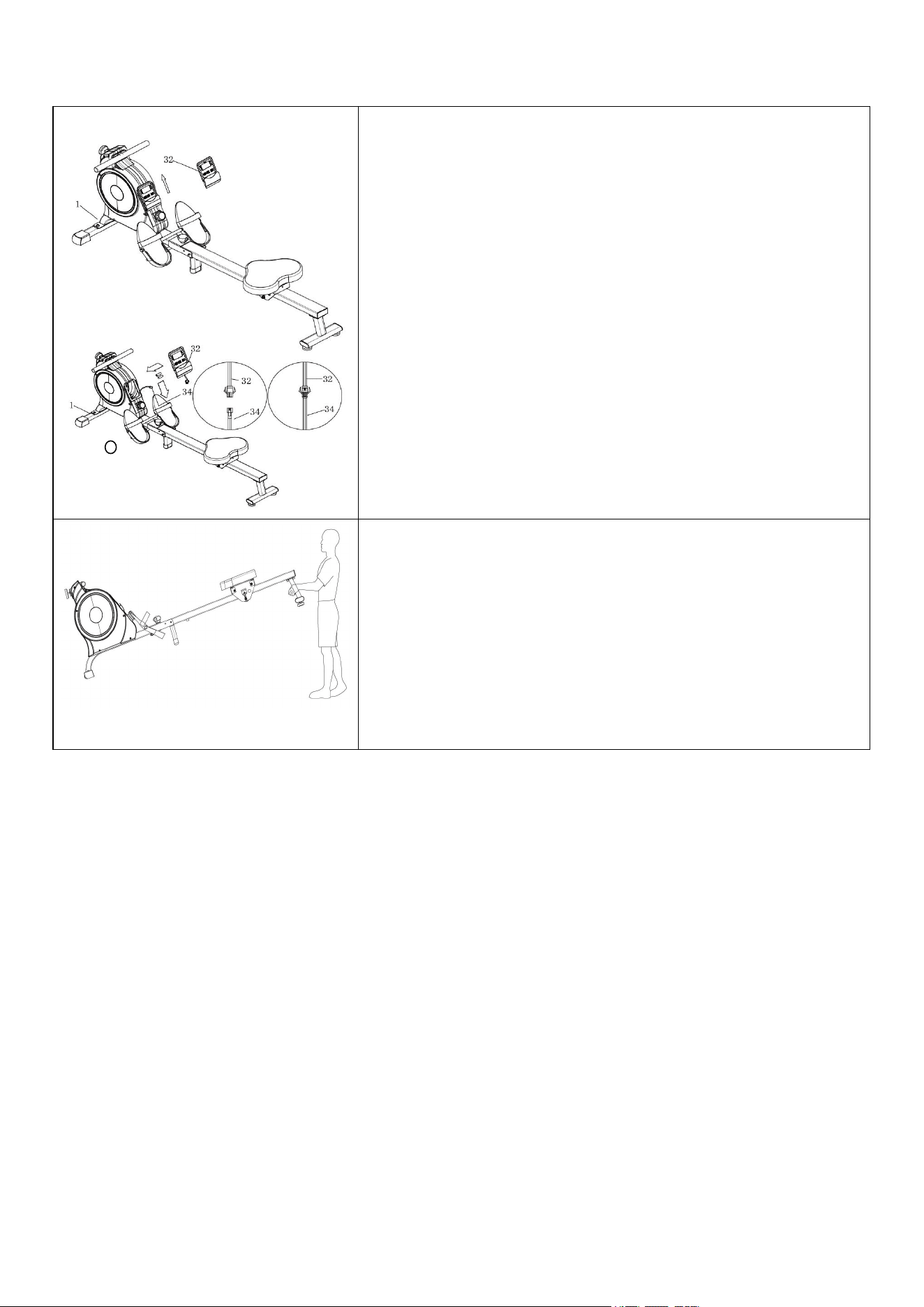
STEP 7:
NOTE: The two upper buckles of
Computer (No. 32) should be aligned to
the two upper slots of computer seat of
Main Frame (No. 1).
Connect Sensor Wire (No. 34) with the
wire of Computer (No. 32). Place
Computer (No. 32) back onto the Main
Frame (No. 1), then push the Computer
(No. 32) downwards to fit into position.
The assembly is complete!
STEP 6:
Take out 2 AAA batteries from the plastic
bag with the manual. Push Computer (No.
32) upward, then remove Computer (No.
32) from Main Frame (No. 1). Disconnect
Sensor Wire (No. 34) and the wire of
Computer (No. 32). Install the 2 AAA
batteries into the back of Computer (No.
32).
8
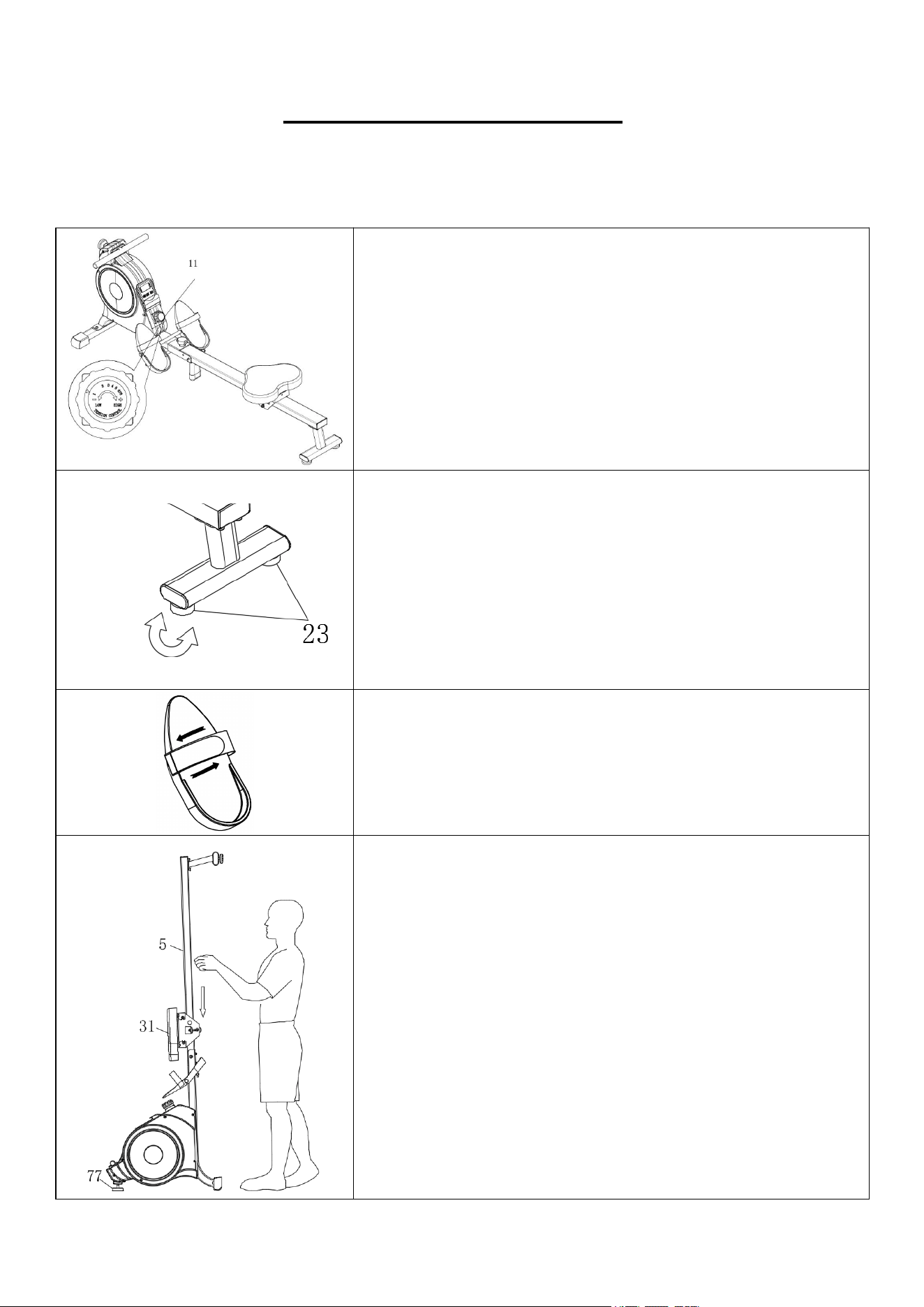
ADJUSTMENTS GUIDE
CAUTION! Moving parts, such as the seat, can crush and cut. Keep hands clear of the sliding rail
during use!
ADJUSTING THE RESISTANCE
Rotate the Tension Control Knob (No. 11) clockwise to
increase the level of resistance. Rotate the Tension Control
Knob (No. 11) counter-clockwise to decrease the level of
resistance.
Tension levels are set at Level 1 being the lowest and Level
8 being the highest.
ADJUSTING THE BALANCE
If you notice that the rower is unbalanced during use, you
should adjust the foot levelers located beneath the rear
support. Rotate Foot Levelers (No. 23) clockwise until it sits
level with the surface that the rower is on. When you have
finished adjusting the foot leveler, re-tighten the Foot
Levelers (No. 23) by rotating it counter-clockwise. If
required, repeat this process to adjust the remaining feet.
PEDAL STRAP ADJUSTMENT
The pedal strap is adjustable and can be personalized to fit
the user’s foot size.
PLACING THE ROWER
When not in use, you can save space by placing the rower
upright on the floor with Foot Leveler (No. 77)
SAFETY NOTE: The Seat (No. 31) will glide down when
placing Sliding Rail (No. 5) in an upright position.
9
Figure B
Figure A
CAUTION!
Move with caution when
you vertically fold the
Sliding Rail (No. 5) as
your head may touch the
Rear Support (No. 14).
3
When not in use, you can save space by folding the Sliding Rail (No. 5).
Pull out the Pull Pin (No. 82) and disassemble Knob (No. 80) (Figure A).
Fold the Sliding Rail (No. 5) to a vertical angle. (Figure B)
SAFETY NOTE: Seat (No. 31) will glide down when folding the Sliding Rail (No. 5).
Reinsert Pull Pin (No. 82) into the hole on the Main Frame (No. 5), then tighten Knob (No. 80) to Sliding
Rail (No. 5). (Figure C)
FOLDING THE ROWER
Figure C
10
REPLACING THE BATTERIES
Two AAA batteries are included in Computer (No. 32). To
replace the batteries, remove Computer (No. 32) from Main
Frame (No. 1), and disconnect the Sensor Wire (No. 34)
and the wire of Computer (No. 32). Replace both batteries.
Do not mix battery types and do not mix old and new
batteries.
After the replacement, connect Sensor Wire (No. 34) to the
wire of Computer (No. 32) and put Computer (No. 32) back
onto the Main Frame (No. 1). Dispose or recycle batteries
according to your state and local rules.
MOVING THE ROWER
To move the rower, lift the rear support until the
transportation wheels on the front stabilizer touch the
ground. Once the wheels are on the ground, you can
transport the rower to the desired location with ease
11
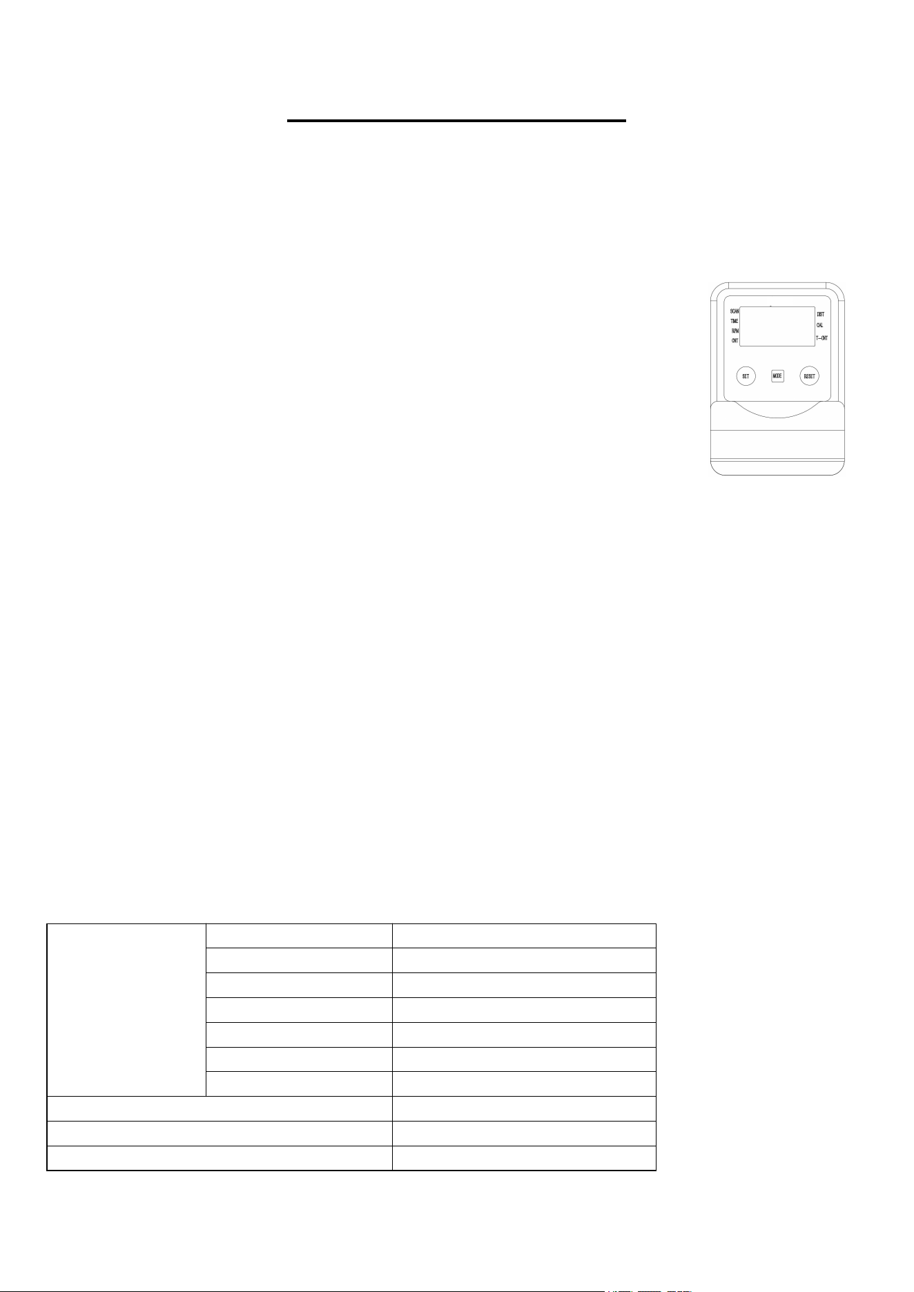
EXERCISE COMPUTER
Our computerized display console on the Magnetic Rowing Machine allows the user to tailor a
personalized workout by monitoring their progress. During a workout, the display console will
alternately and repeatedly display your Time, Count, Calories Burned, Total Count, Distance, and
Scan (all of the above). With our easy-to-use console, the user can efficiently track their fitness
goals from one workout to the next.
FUNCTION KEY:
MODE: To select your specification mode and/or turn on display console.
Press the MODE key and hold it 3 seconds, all the values except Total Count
would be reset to zero.
SET: To set a value of Time, Count, or Calories (when not in Scan mode).
RESET: Press to reset Time, Count, or Calories. Press the RESET key and
hold it 3 seconds, all the values except Total Count would be reset to zero.
FUNCTIONS AND OPERATIONS:
SCAN: Press the MODE button until SCAN appears. The display will rotate through the six
functions in the following order: TIME, DISTANCE, CALORIES, COUNT, TOTAL COUNT, and
RPM. Each display will be held for 6 seconds.
TIME: Counts the total time elapsed during your current workout.
CNT (COUNT): Counts the number of rowing strokes from your current workout.
T-CNT (TOTAL COUNT): Counts the total amount of strokes from the first use.
CAL (CALORIES): Counts the total calories burned from current workout.
DIST (DISTANCE): Counts the total distance during your current workout.
RPM (CN/M): Display the steps per minute while exercising.
AUTO ON/OFF & AUTO START/STOP:
The power will turn off automatically once there’s no signal for 4 minutes. The computer will
reactivate once the rower is put into motion or when a computer key is pressed.
SPECIFICATIONS:
FUNCTIONS
SCAN Every 6 seconds
DIST 0.00~9999 ML(Miles)
TIME 0:00~99:59(Minute:Second)
COUNT 0~9999 Count
RPM (CN/M) 0~999 TIMES/MIN
CALORIES 0.0~999.9 Kcal
TOTAL COUNT 0~9999 Count
BATTERY TYPE (2)Two AAA or UM-4
OPERATING TEMPERATURE 0°C ~40°C
STORAGE TEMPERATURE -10°C ~ 60°C