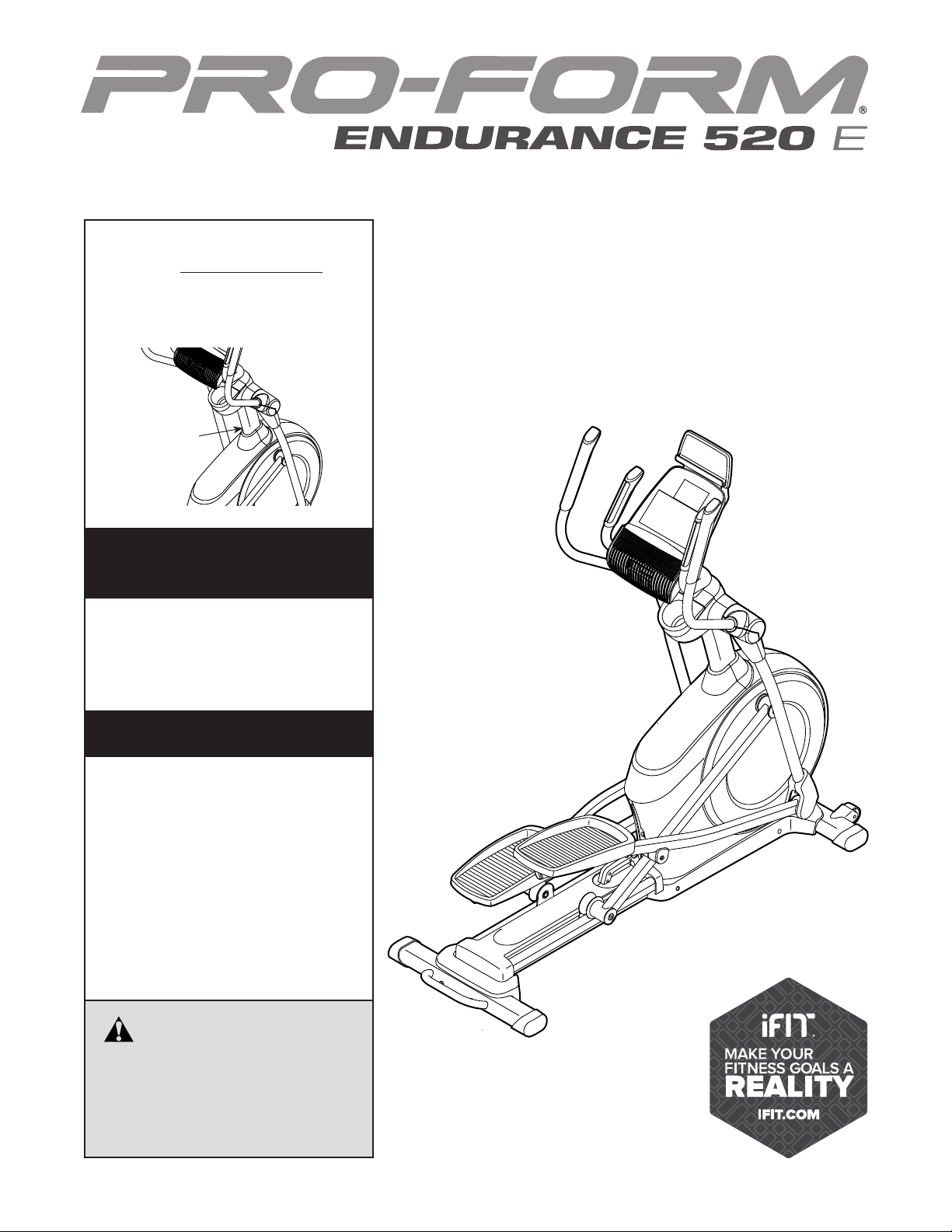
USER’SMANUAL
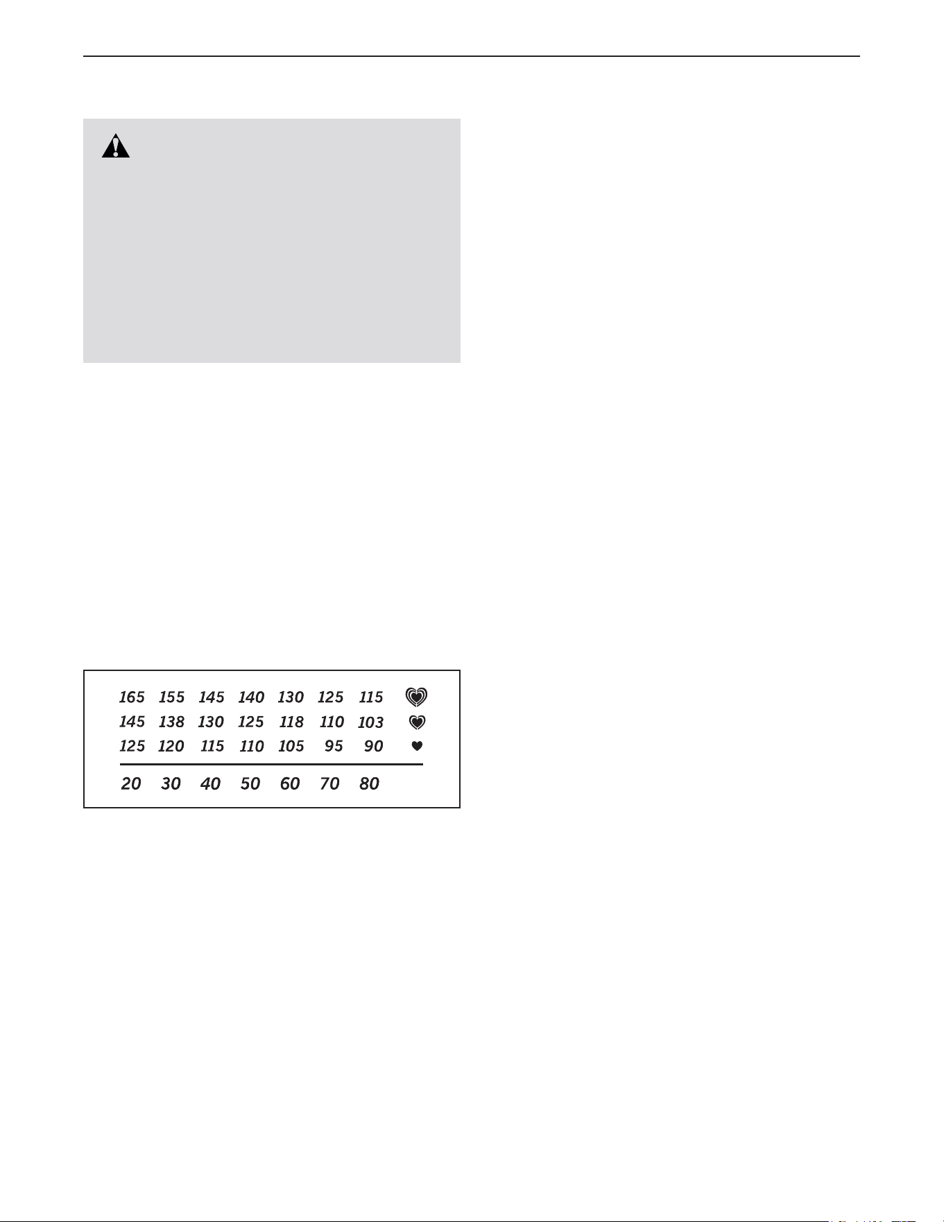
Serial
Number
Decal
CAUTION
Readallprecautionsand
instructionsinthismanualbefore
usingthisequipment.Keepthis
manualforfuturereference.
ModelNo.PFEL55914.4
SerialNo.
Write the serial number in the space
above for reference.
www.proform.com
Toregisteryourproductand
activateyourwarrantytoday,
gotowww.proformservice.com/
registration.
Forserviceatanytime,goto
www.proformservice.com.
Or call 1-888-533-1333
Mon.–Fri. 6 a.m.–6 p.m. MT
Sat. 8 a.m.–12 p.m. MT
Pleasedonotcontactthestore.
ACTIVATEYOUR
WARRANTY
CUSTOMERCARE
2
TABLEOFCONTENTS
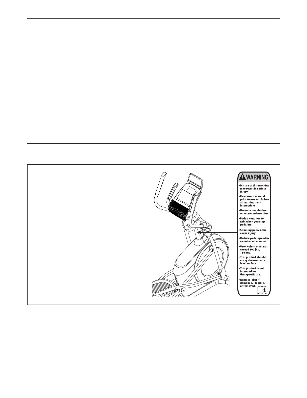
WARNINGDECALPLACEMENT
This drawing shows the location(s) of the warning
decal(s). Ifadecalismissingorillegible,see
thefrontcoverofthismanualandrequesta
freereplacementdecal.Applythedecalinthe
locationshown.Note: The decal(s) may not be
shown at actual size.
WARNING DECAL PLACEMENT . . . . . . . . . . . . . . . . . . . . . . . . . . . . . . . . . . . . . . . . . . . . . . . . . . . . . . . . . . . . . . .2
IMPORTANT PRECAUTIONS . . . . . . . . . . . . . . . . . . . . . . . . . . . . . . . . . . . . . . . . . . . . . . . . . . . . . . . . . . . . . . . . . .3
BEFORE YOU BEGIN. . . . . . . . . . . . . . . . . . . . . . . . . . . . . . . . . . . . . . . . . . . . . . . . . . . . . . . . . . . . . . . . . . . . . . . .6
PART IDENTIFICATION CHART. . . . . . . . . . . . . . . . . . . . . . . . . . . . . . . . . . . . . . . . . . . . . . . . . . . . . . . . . . . . . . . .7
ASSEMBLY . . . . . . . . . . . . . . . . . . . . . . . . . . . . . . . . . . . . . . . . . . . . . . . . . . . . . . . . . . . . . . . . . . . . . . . . . . . . . . . .8
HOW TO USE THE ELLIPTICAL . . . . . . . . . . . . . . . . . . . . . . . . . . . . . . . . . . . . . . . . . . . . . . . . . . . . . . . . . . . . . .18
FCC INFORMATION . . . . . . . . . . . . . . . . . . . . . . . . . . . . . . . . . . . . . . . . . . . . . . . . . . . . . . . . . . . . . . . . . . . . . . . .29
MAINTENANCE AND TROUBLESHOOTING . . . . . . . . . . . . . . . . . . . . . . . . . . . . . . . . . . . . . . . . . . . . . . . . . . . . .30
EXERCISE GUIDELINES . . . . . . . . . . . . . . . . . . . . . . . . . . . . . . . . . . . . . . . . . . . . . . . . . . . . . . . . . . . . . . . . . . . .32
PART LIST. . . . . . . . . . . . . . . . . . . . . . . . . . . . . . . . . . . . . . . . . . . . . . . . . . . . . . . . . . . . . . . . . . . . . . . . . . . . . . . .35
EXPLODED DRAWING. . . . . . . . . . . . . . . . . . . . . . . . . . . . . . . . . . . . . . . . . . . . . . . . . . . . . . . . . . . . . . . . . . . . . .37
ORDERING REPLACEMENT PARTS . . . . . . . . . . . . . . . . . . . . . . . . . . . . . . . . . . . . . . . . . . . . . . . . . . Back Cover
LIMITED WARRANTY. . . . . . . . . . . . . . . . . . . . . . . . . . . . . . . . . . . . . . . . . . . . . . . . . . . . . . . . . . . . . . . Back Cover
Google Maps is a trademark of Google Inc.
IFIT is a registered trademark of ICON Health & Fitness, Inc.
PROFORM is a registered trademark of ICON Health & Fitness, Inc.

3
WARNING:
Toreducetheriskofseriousinjury,readallimportantprecautionsand
instructionsinthismanualandallwarningsonyourellipticalbeforeusingyourelliptical.ICON
assumesnoresponsibilityforpersonalinjuryorpropertydamagesustainedbyorthroughthe
useofthisproduct.
1. Itistheresponsibilityoftheownertoensure
thatallusersoftheellipticalareadequately
informedofallprecautions.
2. Beforebeginninganyexerciseprogram,
consultyourphysician.Thisisespecially
importantforpersonsoverage35orper-
sonswithpre-existinghealthproblems.
3. Theellipticalisnotintendedforuseby
personswithreducedphysical,sensory,or
mentalcapabilitiesorlackofexperienceand
knowledge,unlesstheyaregivensupervi-
sionorinstructionaboutuseoftheelliptical
bysomeoneresponsiblefortheirsafety.
4. Usetheellipticalonlyasdescribedinthis
manual.
5. Theellipticalisintendedforhomeuseonly.
Donotusetheellipticalinacommercial,
rental,orinstitutionalsetting.
6. Keeptheellipticalindoors,awayfrommois-
tureanddust.Donotputtheellipticalina
garageorcoveredpatio,ornearwater.
7. Placetheellipticalonalevelsurface,withat
least3ft.(0.9m)ofclearanceinthefrontand
rearoftheellipticaland2ft.(0.6m)oneach
side.Toprotectthefloororcarpetfromdam-
age,placeamatundertheelliptical.
8. Inspectandproperlytightenallpartseach
timetheellipticalisused.Replaceanyworn
partsimmediately.
9. Keepchildrenunderage13andpetsaway
fromtheellipticalatalltimes.
10.Theellipticalshouldnotbeusedbypersons
weighingmorethan300lbs.(136kg).
11.Wearappropriateclotheswhileexercising;
donotwearlooseclothesthatcouldbecome
caughtontheelliptical.Alwayswearathletic
shoesforfootprotectionwhileexercising.
12.Holdthehandlebarsortheupperbodyarms
whenmounting,dismounting,orusingthe
elliptical.
13.Theheartratemonitorisnotamedical
device.Variousfactorsmayaffecttheaccu-
racyofheartratereadings.Theheartrate
monitorisintendedonlyasanexerciseaid
indeterminingheartratetrendsingeneral.
14.Theellipticaldoesnothaveafreewheel;the
pedalswillcontinuetomoveuntilthefly-
wheelstops.Reduceyourpedalingspeedin
acontrolledway.
15.Keepyourbackstraightwhileusingtheellip-
tical;donotarchyourback.
16.Overexercisingmayresultinseriousinjury
ordeath.Ifyoufeelfaint,ifyoubecomeshort
ofbreath,orifyouexperiencepainwhile
exercising,stopimmediatelyandcooldown.
IMPORTANTPRECAUTIONS

4
5
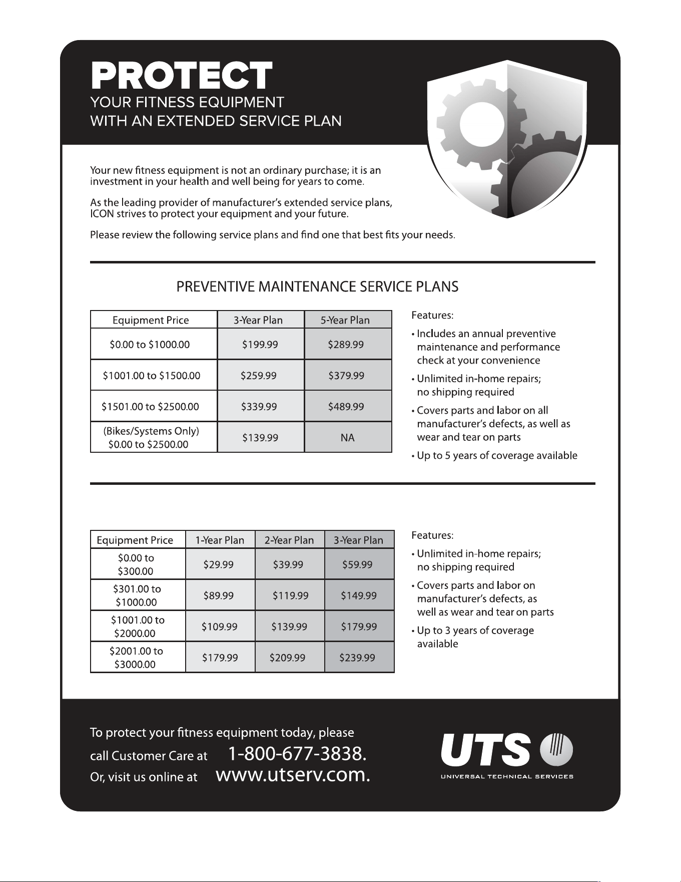
all
STANDARD SERVICE PLANS
6
Thank you for selecting the revolutionary PROFORM
®
ENDURANCE 520 E elliptical. The ENDURANCE 520
E elliptical provides an impressive selection of features
designed to make your workouts at home more effec-
tive and enjoyable.
Foryourbenefit,readthismanualcarefullybefore
youusetheelliptical. If you have questions after
reading this manual, please see the front cover of this
manual. To help us assist you, note the product model
number and serial number before contacting us. The
model number and the location of the serial number
decal are shown on the front cover of this manual.
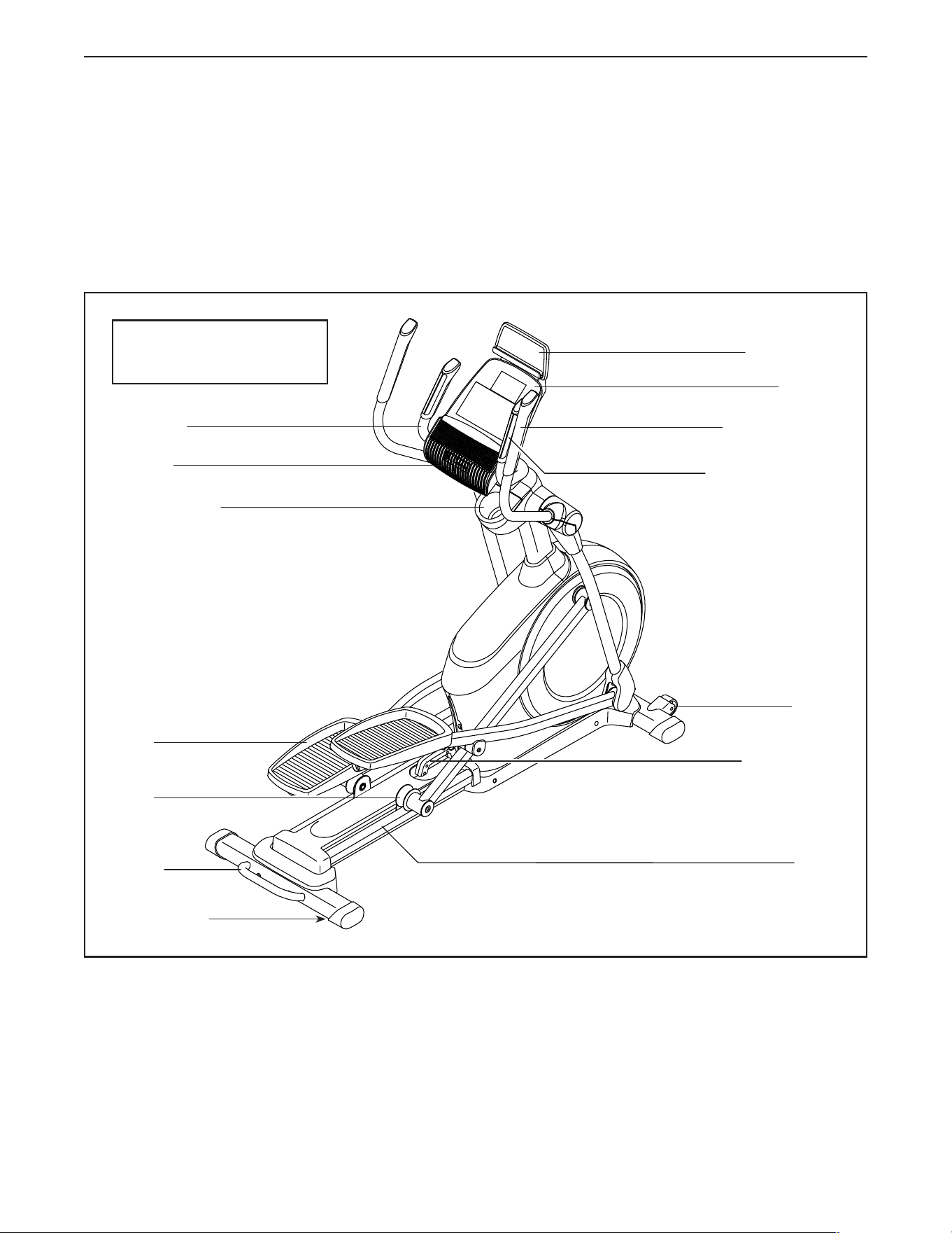
Before reading further, please familiarize yourself with
the parts that are labeled in the drawing below.
Heart Rate Monitor
Accessory Tray
Speaker
Handlebar
Upper Body Arm
Pedal
Roller
Handle
Ramp
Ramp Handle
Console
Tablet Holder
BEFOREYOUBEGIN
Wheel
Leveling Foot
Length: 5 ft. 8 in. (173 cm)
Width: 2 ft. 2 in. (66 cm)
7
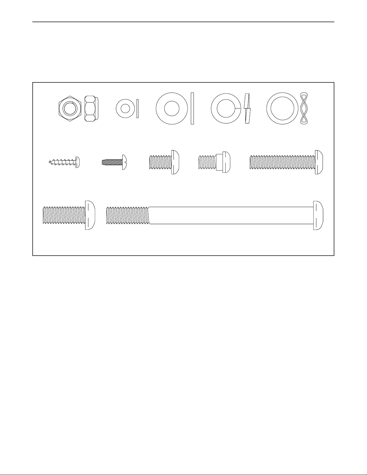
PARTIDENTIFICATIONCHART
Use the drawings below to identify the small parts needed for assembly. The number in parentheses below each
drawing is the key number of the part, from the PART LIST near the end of this manual. The number following the
key number is the quantity needed for assembly. Note:Ifapartisnotinthehardwarekit,checktoseeifit
hasbeenpreassembled.Extrapartsmaybeincluded.
M8 x 13mm
Screw (82)–6
M10 x 25mm
Screw (92)–4
M10 x 122mm Screw
(104)–4
M8 Locknut
(102)–4
M4 x 16mm
Screw (101)–16
16mm Wave
Washer (54)–2
M10 Split
Washer (105)–8
M8 Washer
(97)–8
M5 Washer
(32)–2
M8 x 38mm Bolt
(96)–4
M8 x 14mm
Shoulder
Screw (120)–2
#8 x 12mm
Screw (9)–4
8
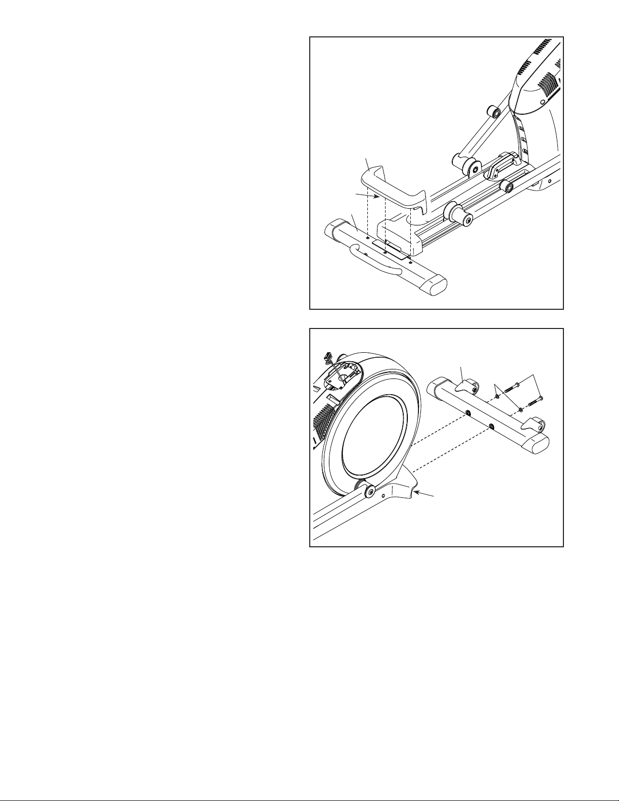
2. With the help of a second person, place some of
the packing materials (not shown) under the rear
of the Frame (1). Havethesecondpersonhold
theFrametopreventitfromtippingwhileyou
completethisstep.
Attach the Rear Stabilizer (2) to the Frame (1)
with two M10 x 122mm Screws (104) and two
M10 Split Washers (105).
Remove the packing materials from under the
rear of the Frame (1).
2
1
2
104
105
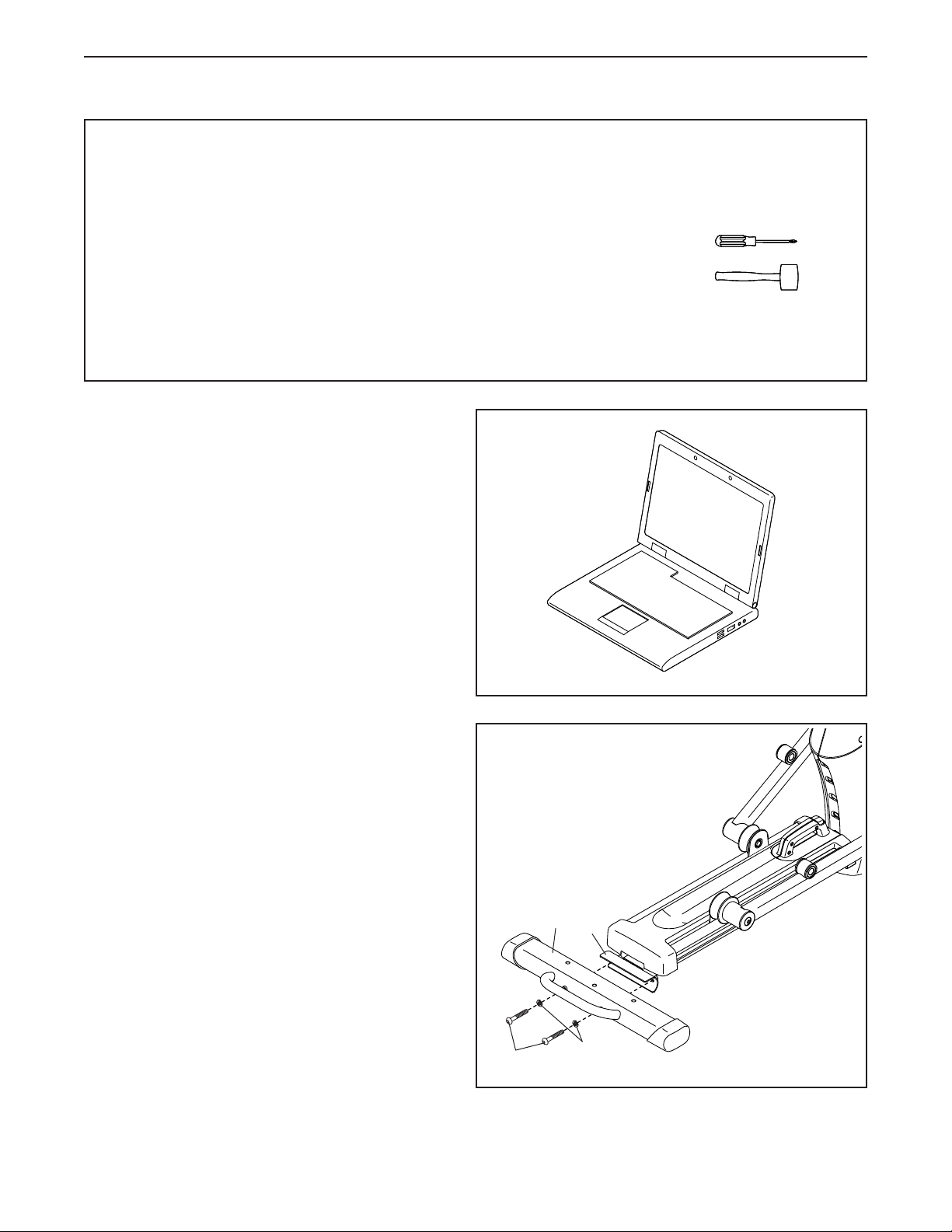
• To hire an authorized service technician to
assemble this product, call 1-800-445-2480.
• Assembly requires two persons.
• Place all parts in a cleared area and remove the
packing materials. Do not dispose of the packing
materialsuntilyou�nishallassemblysteps.
• Left parts are marked “L” or “Left” and right parts
are marked “R” or “Right.”
• To identify small parts, see page 7.
• In addition to the included tool(s), assembly
requires the following tools:
one Phillips screwdriver
one rubber mallet
Assembly may be easier if you have a set of
wrenches. To avoid damaging parts, do not use
power tools.
ASSEMBLY
1. Gotowww.proformservice.com/registration
onyourcomputerandregisteryourproduct.
• activates your warranty
• saves you time if you ever need to contact
Customer Care
• allows us to notify you of upgrades and offers
Note: If you do not have internet access, call
Customer Care (see the front cover of this
manual) and register your product.
1
9
3
2
106
15
3. Press the Cover Mounts (106) on the underside
of the Rear Stabilizer Cover (15) into the Rear
Stabilizer (2).
4
4. With the help of a second person, place some
of the packing materials (not shown) under the
front of the Frame (1). Havethesecondper-
sonholdtheFrametopreventitfromtipping
whileyoucompletethisstep.
Attach the Front Stabilizer (6) to the Frame (1)
with two M10 x 122mm Screws (104) and two
M10 Split Washers (105).
Remove the packing materials from under the
front of the Frame (1).
1
6
104
105
10
5
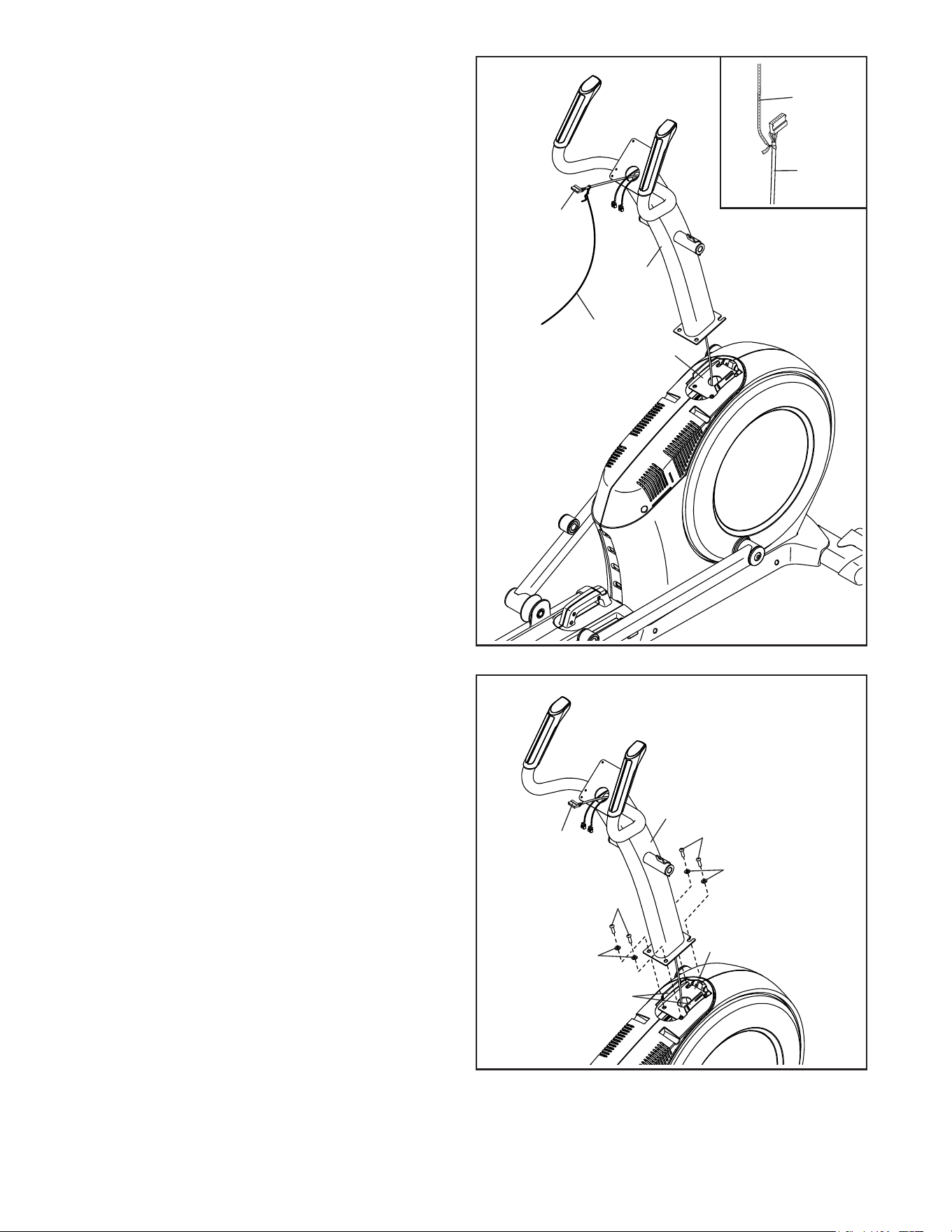
5. Orient the Upright (4) as shown. Have a second
person hold the Upright near the Frame (1).
Seetheinsetdrawing. Locate the wire tie in
the lower end of the Upright (4). Tie the wire tie
to the Upper Wire (110). Then, pull the upper
end of the wire tie until the Upper Wire is routed
through the Upright.
Tip:TopreventtheUpperWire(110)from
fallingintotheUpright(4),securetheUpper
Wirewiththewiretie.
1
4
110
Wire
Tie
Wire
Tie
110
6
6. Tip:AvoidpinchingtheUpperWire(110).
Avoiddamagingtheindicatedplastictabs.
Set the Upright (4) on the Frame (1).
Attach the Upright (4) with four M10 x 25mm
Screws (92) and four M10 Split Washers (105);
startalloftheScrews,andthentightenthem.
AvoidpinchingtheUpper
Wire(110)andavoid
damagingthetabs
Tabs
4
1
105
105
92
92
110
11
7
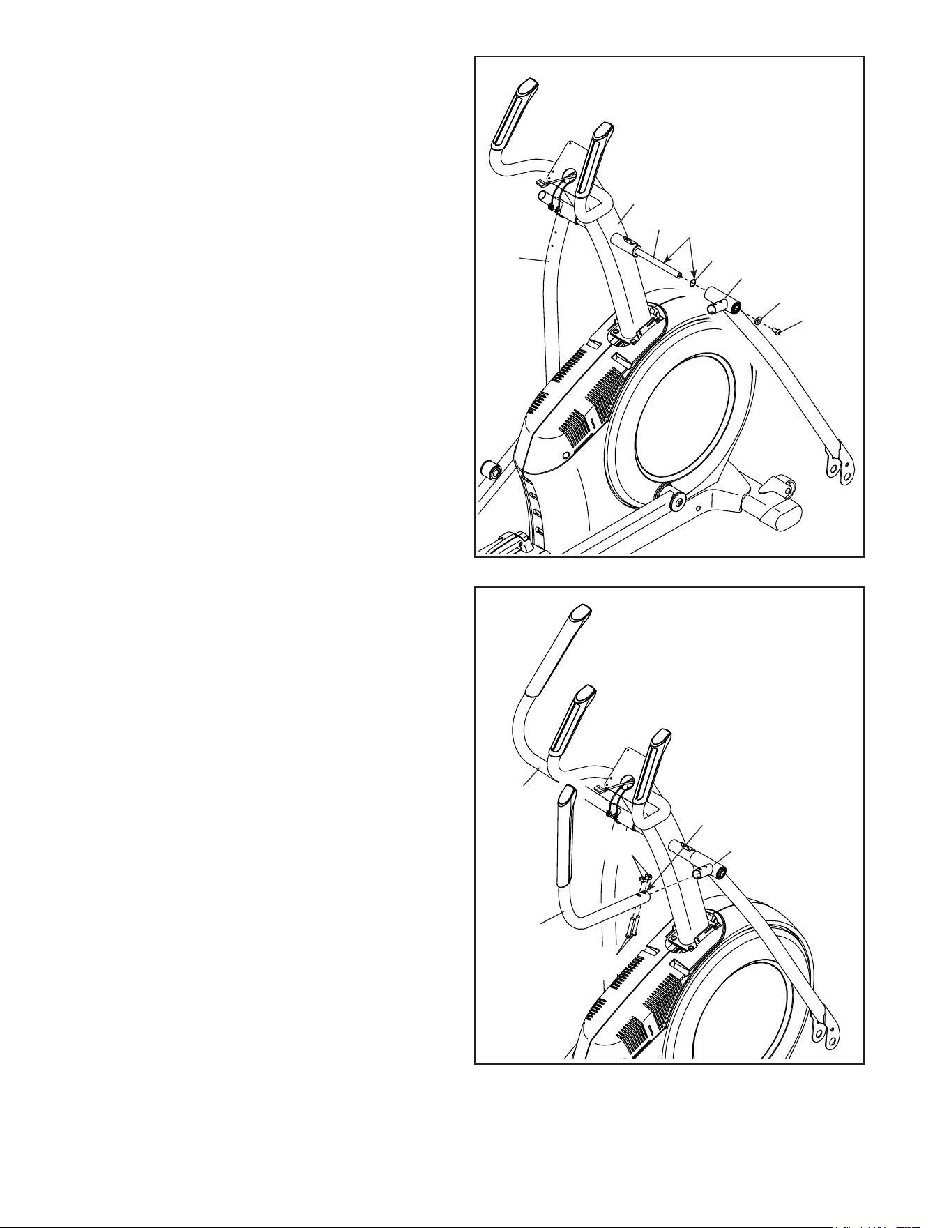
7. Using a plastic bag to keep your fingers clean,
apply some of the included grease to the Pivot
Axle (35) and to two 16mm Wave Washers (54).
Insert the Pivot Axle (35) through the Upright (4)
and center it. Tip:Itmaybehelpfultousea
rubbermallet.
Identify the Right Upper Body Leg (60) and
orient it as shown.
Slide a 16mm Wave Washer (54) and the Right
Upper Body Leg (60) onto the right side of the
Pivot Axle (35).
RepeattheseactionsfortheLeftUpperBody
Leg(46).
Tighten an M8 x 13mm Screw (82) and an M8
Washer (97) into each end of the Pivot Axle (35)
atthesametime.
60
54
46
82
97
35
4
Grease
8
8. Identify the Right Upper Body Arm (61) and
orient it as shown.
Slide the Right Upper Body Arm (61) onto the
Right Upper Body Leg (60).
Attach the Right Upper Body Arm (61) with two
M8 x 38mm Bolts (96) and two M8 Locknuts
(102).MakesurethattheLocknutsareinthe
hexagonalholes.
RepeatthisstepfortheLeftUpperBody
Arm(47).
Hexagonal
Holes
60
61
47
96
102
12
9
7
4
63
110
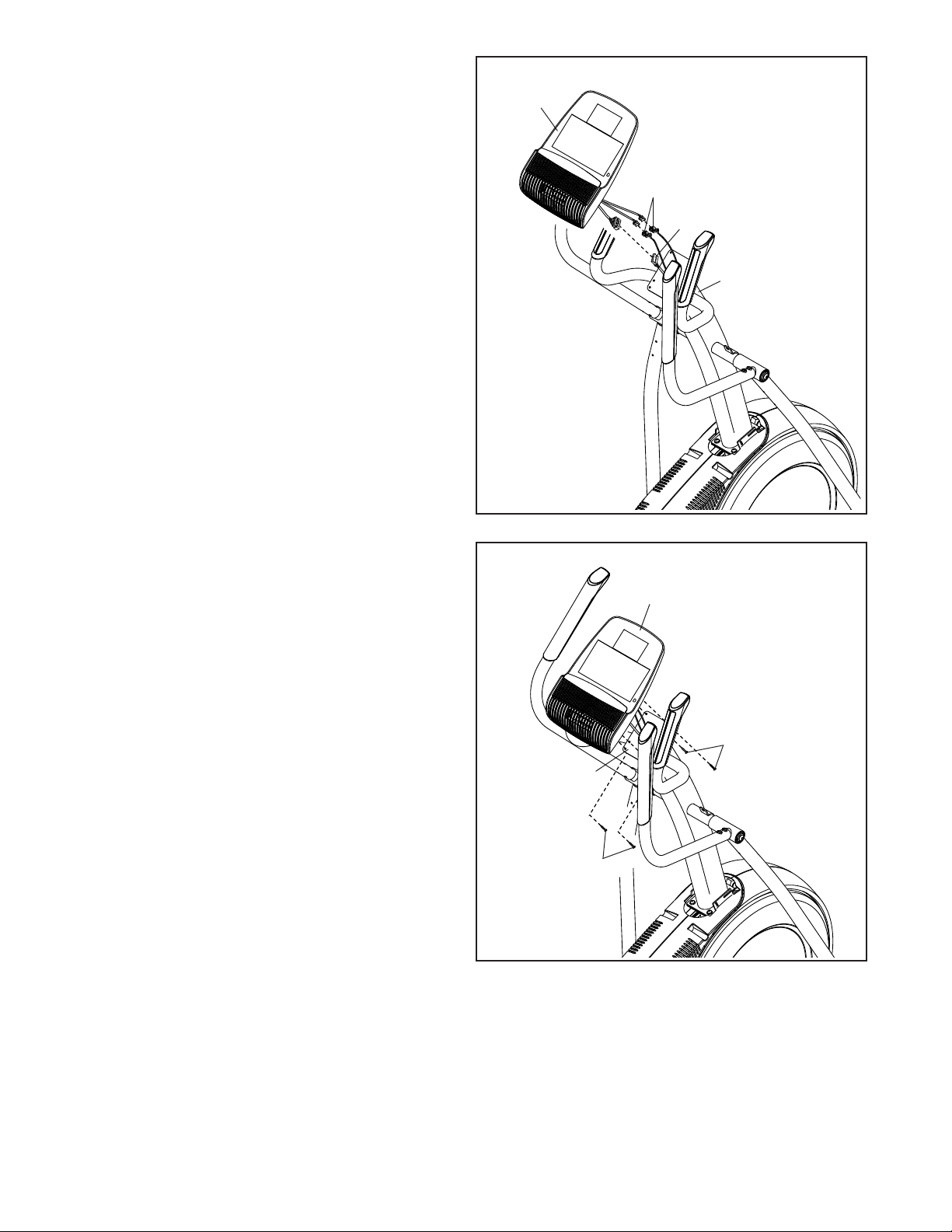
9. Untie and discard the wire tie on the Upper
Wire (110).
While a second person holds the Console (7)
near the Upright (4), connect the wires on the
Console to the Upper Wire (110) and to the
Pulse Sensor Wires (63).
Insert the excess wire into the Upright (4) or into
the Console (7).
10
Avoidpinching
thewires
7
10.Tip:Avoidpinchingthewires. Attach
the Console (7) to the Upright (4) with four
M4 x 16mm Screws (101); startalltheScrews,
andthentightenthem.
101
101
4
13
11
11. Orient the Right Pedal Arm (58) as shown.
Apply grease to the axle on the Right Pedal
Arm (58).
Attach the Right Pedal Arm (58) to the Right
Roller Arm (59) with an M8 x 14mm Shoulder
Screw (120), a Small Axle Cover (55), and an
M8 Washer (97).
RepeatthisstepfortheLeftPedalArm(44).
Grease
55
58
59
44
97
82
82
97
97
77
60
46
64
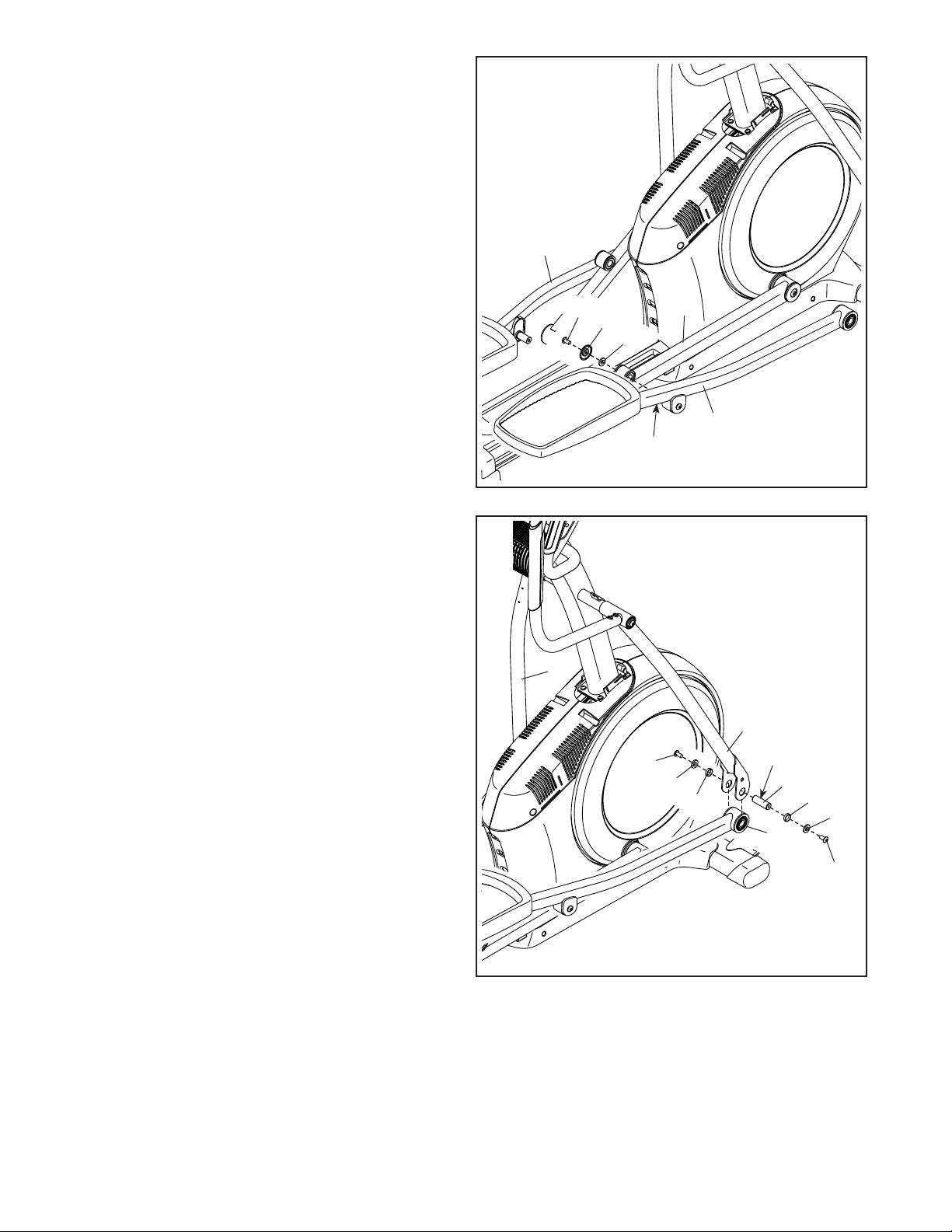
12. Apply a small amount of grease to one of the
Pedal Arm Axles (64).
Next, slide an M8 Washer (97) and an Axle
Spacer (77) onto an M8 x 13mm Screw (82), and
tighten the Screw a few turns into the Pedal Arm
Axle (64).
While a second person holds the front end of the
Right Pedal Arm (58) inside the bracket on the
Right Upper Body Leg (60), insert the Pedal Arm
Axle (64) into both parts.
Slide an M8 Washer (97) and an Axle Spacer
(77) onto another M8 x 13mm Screw (82), and
tighten the Screw a few turns into the Pedal Arm
Axle (64). Then,tightenbothScrewsatthe
sametime.
Repeatthisstepontheothersideofthe
elliptical.
Grease
12
58
120
77
14
13
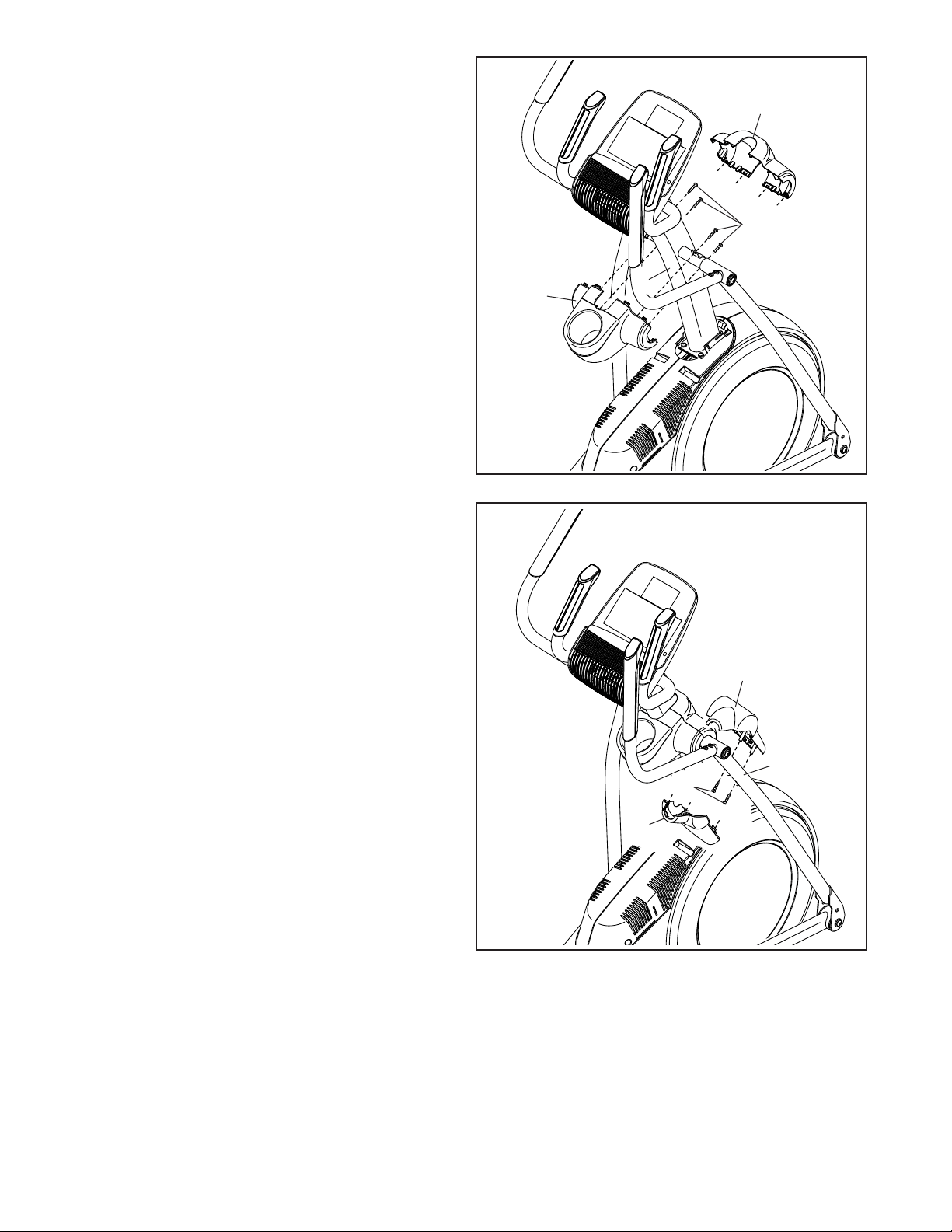
13. Orient the Rear Upright Cover (81) as shown.
Attach the Rear Upright Cover (81) to the Upright
(4) with four M4 x 16mm Screws (101); startall
oftheScrews,andthentightenthem.
Orient the Front Upright Cover (117) as shown.
Attach the Front Upright Cover (117) around the
Upright (4) by pressing it onto the Rear Upright
Cover (81).
101
81
117
4
14
14. Identify the Right Arm Front Cover (65) and
orient it as shown.
Attach the Right Arm Front Cover (65) to the
Right Upper Body Leg (60) with two M4 x 16mm
Screws (101).
Identify the Right Arm Rear Cover (66) and orient
it as shown.
Attach the Right Arm Rear Cover (66) around the
Right Upper Body Leg (60) by pressing it onto
the Right Arm Front Cover (65).
Repeatthisstepontheothersideofthe
elliptical.
65
60
101
66
15
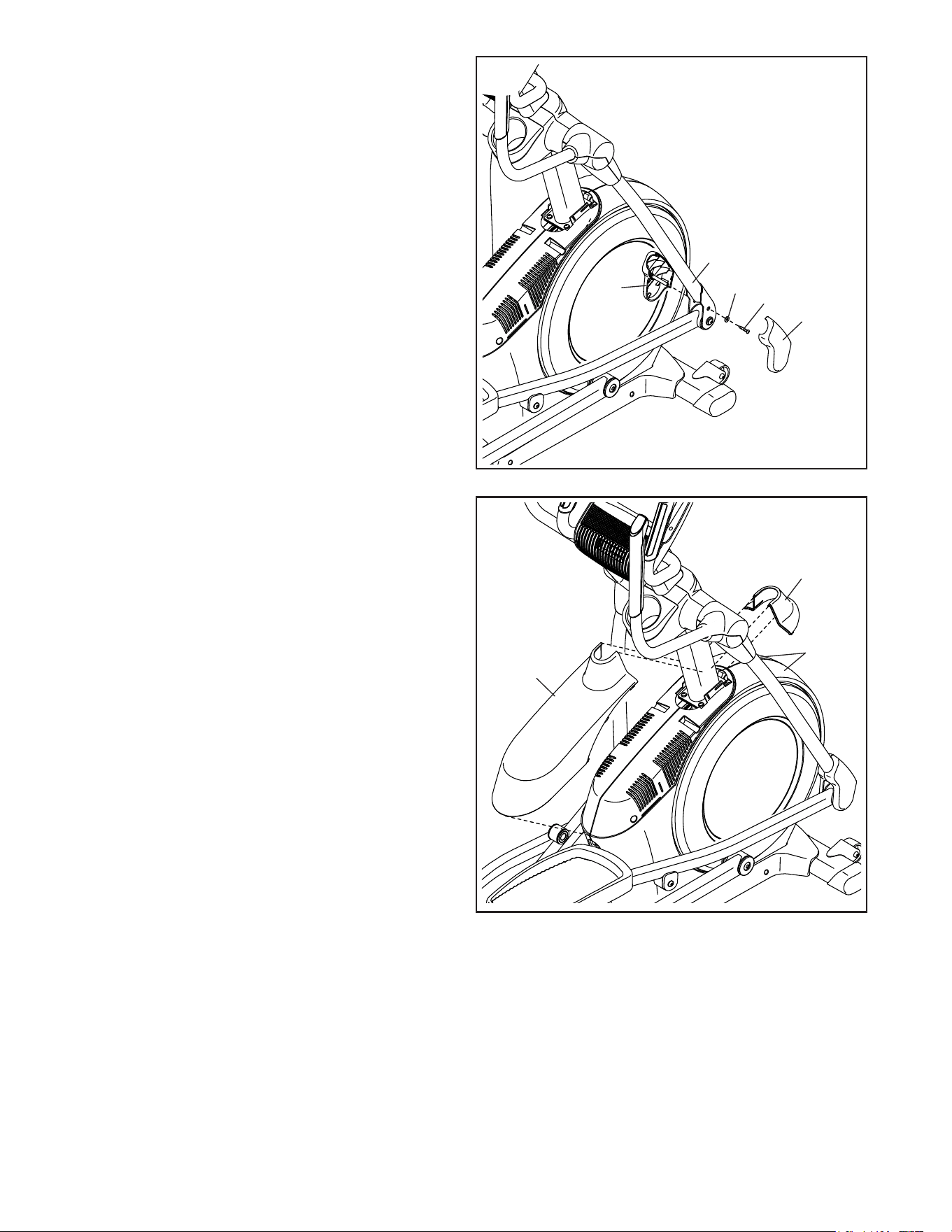
15. Identify the Right Leg Inner Cover (83) and orient
it as shown.
Attach the Right Leg Inner Cover (83) to the
Right Upper Body Leg (60) with an M4 x 16mm
Screw (101) and an M5 Washer (32).
Identify the Right Leg Outer Cover (69) and
orient it as shown.
Attach the Right Leg Outer Cover (69) around
the Right Upper Body Leg (60) by pressing it
onto the Right Leg Inner Cover (83).
Repeatthisstepontheothersideofthe
elliptical.
60
83
32
101
69
15
16
75
118
73, 74
16. Orient the Shield Cover Cap (118) and the Shield
Cover (75) as shown.
First, press the tabs on the Shield Cover Cap
(118) into the Left and Right Shields (73, 74).
Then, press the tabs on the Shield Cover (75)
into the Left and Right Shields (73, 74).
16
17
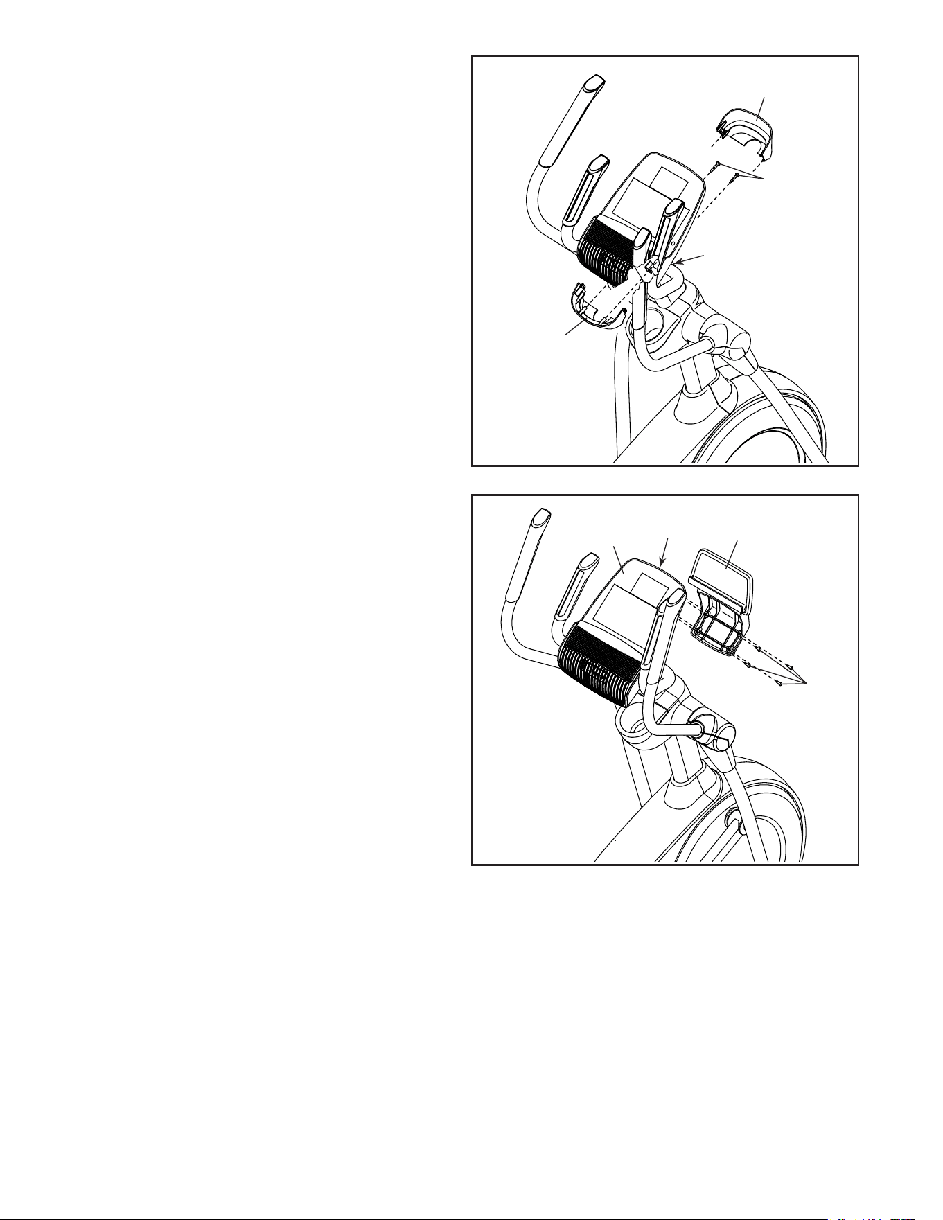
17. Orient the Rear Console Cover (80) as shown.
Attach the Rear Console Cover (80) to the
Upright (4) with two M4 x 16mm Screws (101).
Orient the Front Console Cover (79) as shown.
Attach the Front Console Cover (79) around the
Upright (4) by pressing it onto the Rear Console
Cover (80).
79
4
80
101
121
9
18
18. IMPORTANT:Ifyoupurchasedtheoptional
iFitmodule,inserttheiFitmoduleintothe
iFitportontheConsole(7)beforeyouattach
theTabletHolder(121).Aftertheellipticalis
assembled,followtheinstructionsincluded
withtheiFitmodule.
Attach the Tablet Holder (121) to the Console (7)
with four #8 x 12mm Screws (9); startallofthe
Screws,andthentightenthem.
7
iFit Port
17
119
19
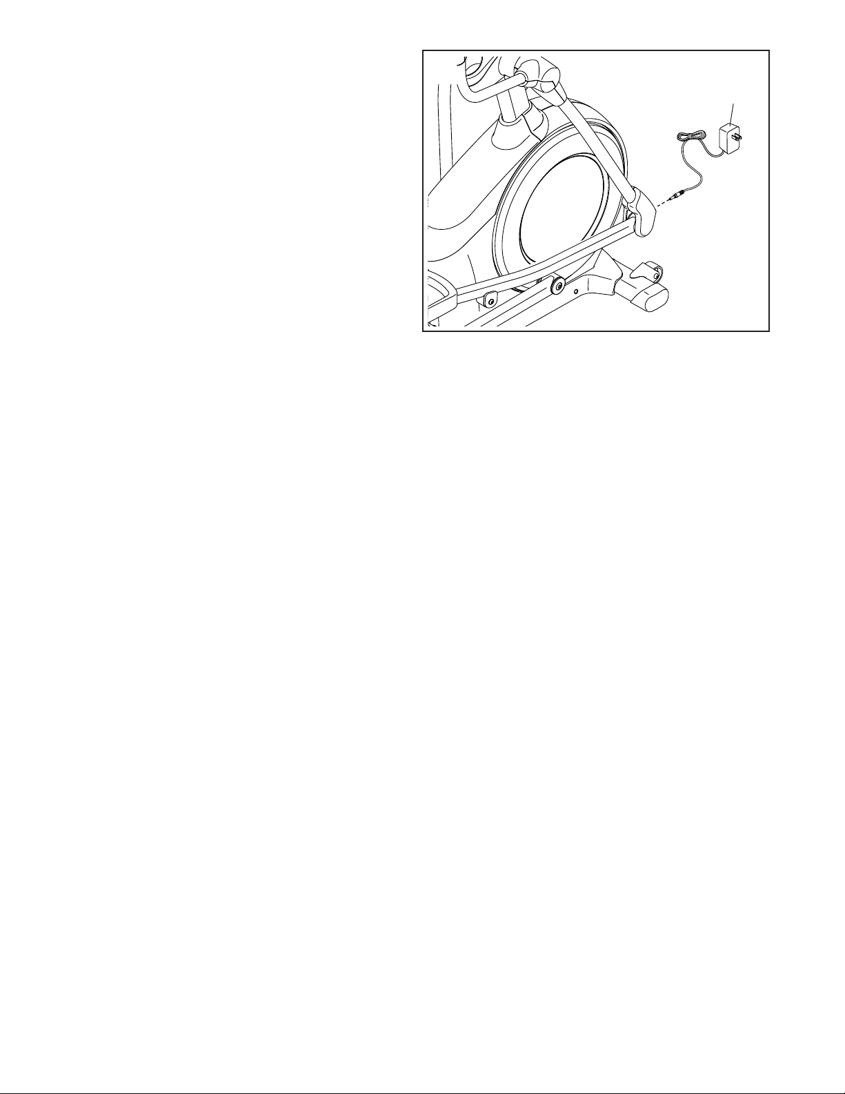
19. Plug the Power Adapter (119) into the receptacle
on the frame of the elliptical.
Note: To plug the Power Adapter (119) into an
outlet, see HOW TO PLUG IN THE POWER
ADAPTER on page 18.
20. Makesurethatallpartsareproperlytightenedbeforeyouusetheelliptical. Extra parts may be included.
Place a mat beneath the elliptical to protect the floor.
18
HOWTOPLUGINTHEPOWERADAPTER
IMPORTANT:Iftheellipticalhasbeenexposedto
coldtemperatures,allowittowarmtoroomtem-
peraturebeforeyoupluginthepoweradapter.If
youdonotdothis,youmaydamagetheconsole
displaysorotherelectroniccomponents.
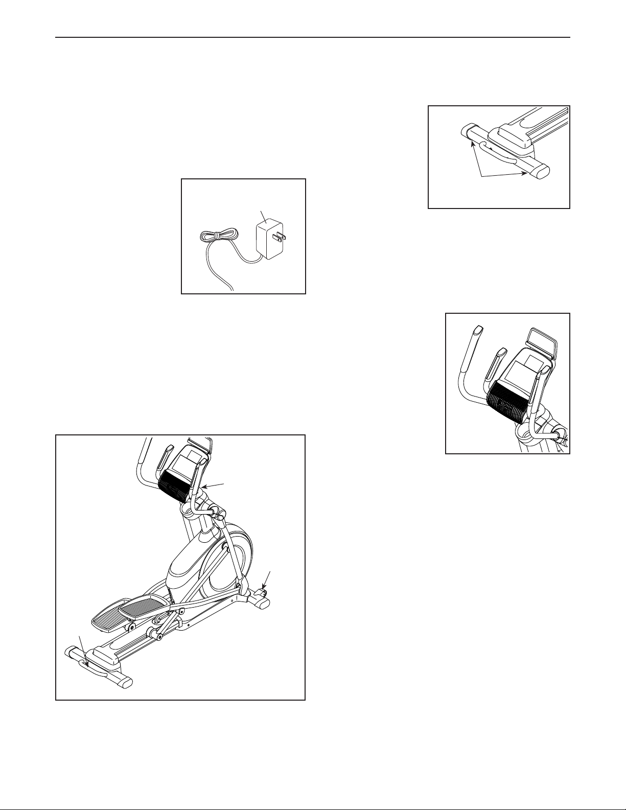
Plug the power adapter
into the receptacle on
the front of the ellipti-
cal. Then, plug the
power adapter into an
appropriate outlet that
is properly installed
in accordance with
all local codes and
ordinances.
HOWTOMOVETHEELLIPTICAL
Duetothesizeandweightoftheelliptical,moving
itrequirestwopersons. Stand in front of the elliptical,
hold the upright, and place one foot against one of the
wheels. Pull on the upright and have a second person
lift the handle until the elliptical will roll on the wheels.
Carefully move the elliptical to the desired location, and
then lower it to the floor.
HOWTOLEVELTHEELLIPTICAL
If the elliptical rocks
slightly on your
floor during use,
turn one or both
of the leveling feet
beneath the rear of
the frame until the
rocking motion is
eliminated.
HOWTOUSETHETABLETHOLDER
IMPORTANT:Thetabletholderwasdesignedfor
usewithmostfull-sizetablets.Donotplaceany
otherelectronicdeviceorobjectintothetablet
holder.
To insert a tablet into
the tablet holder, set
the bottom edge of the
tablet in the tray. Make
surethatthetabletis
firmlysecuredinthe
tabletholder.Reverse
these actions to
remove the tablet from
the tablet holder.
HOWTOUSETHEELLIPTICAL
Power Adapter
Leveling
Feet
Pull on the
upright
Place
your foot
here
Lift
here
19
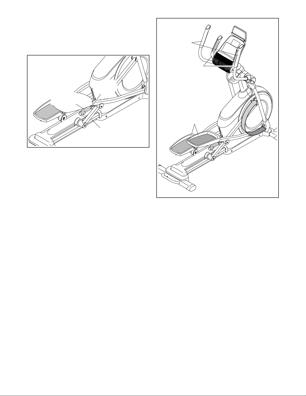
HOWTOCHANGETHEINCLINEOFTHERAMP
To vary the motion of the pedals, you can change the
incline of the ramp. To raise the ramp, simply pull the
ramp handle upward to the desired incline level.
To lower the ramp, press the latch button, pull the ramp
handle, and lower the ramp to the desired incline level.
Then, release the latch button and engage the latch
pin into one of the adjustment holes in the frame. Make
surethatthelatchpinisfirmlyengagedinoneof
theadjustmentholesintheframe.
HOWTOEXERCISEONTHEELLIPTICAL
To mount the elliptical, hold the handlebars or the
upper body arms and step onto the pedal that is in the
lower position. Then, step onto the other pedal. Push
the pedals until they begin to move with a continuous
motion. Note:Thepedalscanturnineitherdirec-
tion.Itisrecommendedthatyouturnthepedals
inthedirectionshownbythearrow;however,for
variety,youcanturnthepedalsintheopposite
direction.
To dismount the elliptical, wait until the pedals come to
a complete stop. Note:Theellipticaldoesnothave
afreewheel;thepedalswillcontinuetomoveuntil
theflywheelstops. When the pedals are stationary,
step off the higher pedal first. Then, step off the lower
pedal.
Handlebars
Upper
Body Arms
Pedals
Ramp
Ramp
Handle
Latch
Button
20
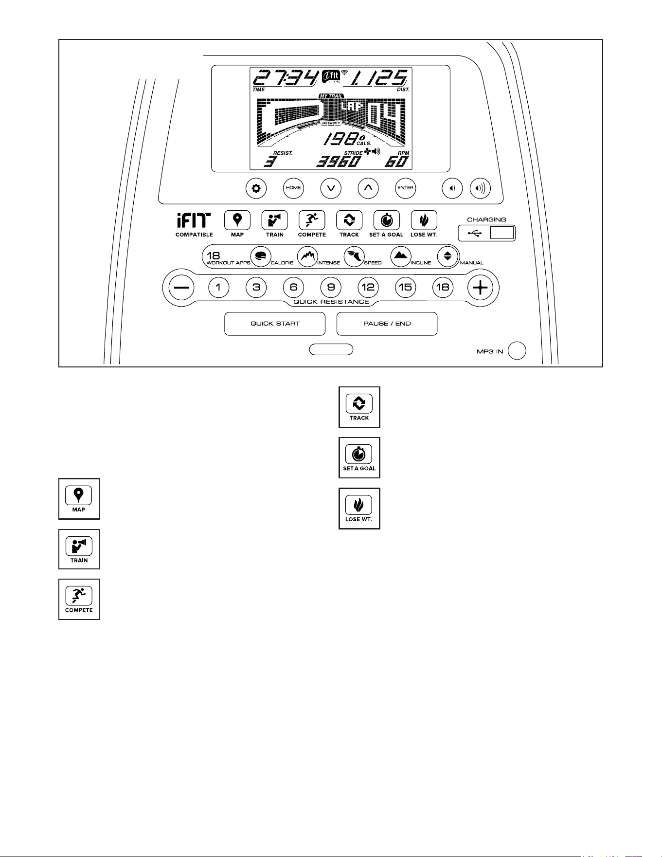
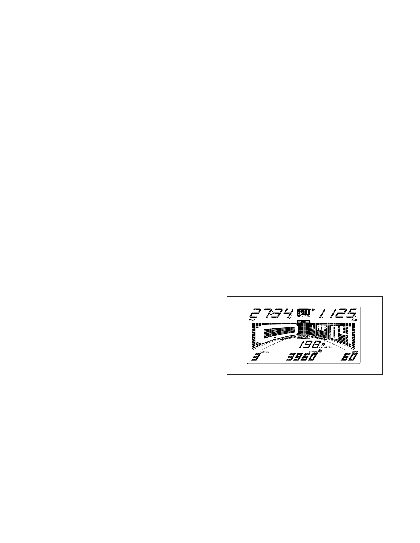
CONSOLEDIAGRAM
MAKEYOURFITNESSGOALSAREALITYWITH
IFIT.COM
With your new iFit-compatible fitness equipment, you
can use an array of features on iFit.com to make your
fitness goals a reality:
Exercise anywhere in the world with
customizable Google Maps.
Download training workouts designed to
help you reach your personal goals.
Measure your progress by competing
against other users in the iFit community.
Upload your workout results to the iFit cloud
and track your accomplishments.
Set calorie, time, or distance goals for your
workouts.
Choose and download sets of weight-loss
workouts.
GotoiFit.comtolearnmore.
21
FEATURESOFTHECONSOLE
The advanced console offers an array of features
designed to make your workouts more effective and
enjoyable.
When you use the manual mode, you can change the
resistance of the pedals with the touch of a button.
While you exercise, the console will display continuous
exercise feedback. You can also measure your heart
rate using the handgrip heart rate monitor.
The console also offers a selection of onboard
workouts. Each workout automatically changes the
resistance of the pedals as it guides you through an
effective workout. You can also set a calorie, distance,
or time goal.
The console also features an iFit mode that enables
the console to communicate with your wireless network
through an optional iFit module. With the iFit mode,
you can download personalized workouts, create your
own workouts, track your workout results, race against
other iFit users, and access many other features.
TopurchaseaniFitmoduleatanytime,goto
www.iFit.comorcallthetelephonenumberonthe
frontcoverofthismanual.
You can even connect your personal audio player to
the console sound system and listen to your favorite
music or audio books while you exercise.
You can also use the charging port on the console
to charge your USB-compatible device while you
exercise.
Tousethemanualmode, see this page. Touse
anonboardworkout, see page 23. Tousea
set-a-goalworkout, see page 25. TouseaniFit
workout, see page 26. Tousethesoundsystem,
see page 27. Tousethechargingport, see page
27. Tochangeconsolesettings, see page 28.
Note: If there is a sheet of plastic on the display,
remove the plastic.
Note: The console can display speed and distance in
either miles or kilometers. To find which unit of mea-
surement is selected, see step 3 on page 28. For
simplicity, all instructions in this section refer to miles.
HOWTOUSETHEMANUALMODE
1. Beginpedalingorpressanybuttononthe
consoletoturnontheconsole.
When you turn on the console, the display will turn
on. The console will then be ready for use.
2. Selectthemanualmode.
Press the Manual button or the Home button to
select the manual mode.
If a wireless iFit module is not inserted into the
console and connected to iFit, the manual mode
will be selected automatically.
3. Changetheresistanceofthepedalsasdesired.
As you pedal, change the resistance of the pedals
by pressing the Quick Resistance increase and
decrease buttons or by pressing one of the num-
bered Quick Resistance buttons.
Note: After you press a button, it will take a
moment for the pedals to reach the selected
resistance level.
4. Followyourprogresswiththedisplay.
The display can show the following workout
information:
22
Calories(Cals.)—This display mode will show the
approximate number of calories you have burned.
CaloriesperHour(Cals./Hr)—This display mode
will show the approximate number of calories you
are burning per hour.
Distance(Dist.)—This display mode will show
the distance that you have pedaled in miles or
kilometers.
Pulse—This display mode will show your heart rate
when you use the handgrip heart rate monitor (see
step 5).
Resistance(Resist.)—This display mode will
show the resistance level of the pedals.
RPM—This display mode will show your pedaling
speed in revolutions per minute (rpm).
Stride—This display mode will show the total
number of strides you have pedaled.
Time—When the manual mode is selected, this
display mode will show the elapsed time. When a
workout is selected, this display mode will show the
time remaining in the workout.
The matrix offers several display tabs. Press the
increase and decrease buttons next to the Enter
button until the desired tab is shown.
Speed—This tab will show a profile of the speed
settings of the workout. A new segment will appear
at the end of each minute.
MyTrail—This tab will show a track that represents
1/4 mile (400 m). As you exercise, the flashing
rectangle will show your progress. The My Trail tab
will also show the number of laps you complete.
Calorie—This tab will show the approximate
amount of calories you have burned. The height of
each segment represents the amount of calories
burned during that segment.
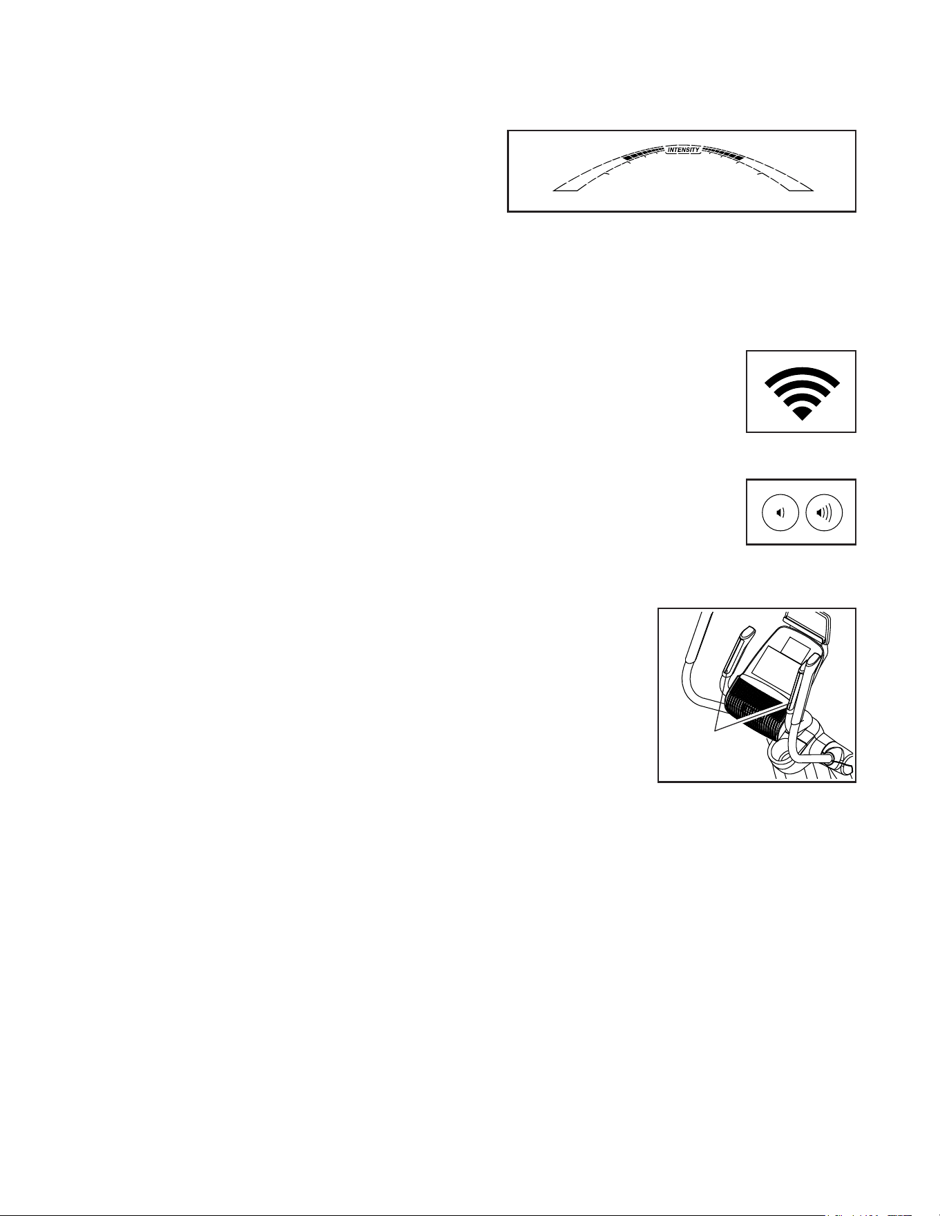
As you exercise, the workout intensity level bar
will indicate the approximate intensity level of your
exercise.
Press the Home button to exit the workout and
return to the default menu (see HOW TO CHANGE
CONSOLE SETTINGS on page 28 to set the
default menu). If necessary, press the Home button
again.
When a wireless iFit module
is connected, the wireless
symbol at the top of the dis-
play will show the strength of
your wireless signal. Four arcs
indicate full signal strength.
Change the volume level of
the console by pressing the
volume increase and decrease
buttons.
5. Measureyourheartrateifdesired.
Ifthereare
sheetsofplas-
ticonthemetal
contactsonthe
handgripheart
ratemonitor,
removetheplas-
tic.To measure
your heart rate,
hold the handgrip
heart rate monitor
with your palms resting against the contacts.Avoid
movingyourhandsorgrippingthecontacts
tightly.
Contacts

23
When your pulse is detected, a heart symbol will
flash in the display each time your heart beats,
one or two dashes will appear, and then your heart
rate will be shown. Forthemostaccurateheart
ratereading,holdthecontactsforatleast15
seconds.
If the display does not show your heart rate, make
sure that your hands are positioned as described.
Be careful not to move your hands excessively or
to squeeze the contacts tightly. For optimal perfor-
mance, clean the contacts using a soft cloth; never
usealcohol,abrasives,orchemicalstoclean
thecontacts.
6. Whenyouarefinishedexercising,theconsole
willturnoffautomatically.
If the pedals do not move for several seconds, a
series of tones will sound, the console will pause,
and the time will flash in the display.
If the pedals do not move for several minutes, the
console will turn off and the display will be reset.
Note: The console features a display demo mode,
designed to be used if the elliptical is displayed in a
store. When the demo mode is turned on, the con-
sole will show a preset presentation. To turn off the
demo mode, see HOW TO CHANGE CONSOLE
SETTINGS on page 28.
HOWTOUSEANONBOARDWORKOUT
1. Beginpedalingorpressanybuttononthe
consoletoturnontheconsole.
When you turn on the console, the display will turn
on. The console will then be ready for use.
2. Selectanonboardworkout.
To select an onboard workout, press the Calorie,
Intense, Speed, or Incline button repeatedly until
the desired workout appears in the display.
When you select an onboard workout, the display
will show the duration of the workout and the name
of the workout. A profile of the speed settings of the
workout will appear in the matrix.
The display will also show the maximum pedaling
speed (rpm) and the maximum resistance level.
Note: If you select an Incline workout, adjust the
ramp to the desired incline level before you start the
workout.
3. Starttheworkout.
Press the Quick Start button or begin pedaling to
start the workout.
Each workout is divided into one-minute segments.
One resistance level and one target rpm (speed)
are programmed for each segment. Note: The
same resistance level and/or target rpm may be
programmed for consecutive segments.
The resistance level and the target rpm for the first
segment will appear in the matrix.
During
the work-
out, the
profile on
the speed
tab will
show your
progress.
The flashing segment of the profile represents the
current segment of the workout. The height of the
flashing segment indicates the target rpm for the
current segment.
Profile

24
At the end of each segment of the workout, a
series of tones will sound and the next segment of
the profile will begin to flash. If a different resis-
tance level and/or target rpm is programmed for
the next segment, the resistance level and/or target
rpm will appear in the display for a few seconds
to alert you. The resistance of the pedals will then
change.
As you exercise, you will be prompted to keep your
pedaling speed near the target rpm for the cur-
rent segment. Whenanupward-pointingarrow
appearsinthedisplay, increase your pace. When
adownward-pointingarrowappears, decrease
your pace. Whennoarrowappears, maintain
your current pace.
IMPORTANT:Thetargetrpmisintendedonlyto
providemotivation.Youractualpedalingspeed
maybeslowerthanthetargetrpm.Makesure
topedalataspeedthatiscomfortableforyou.
If the resistance level for the current segment is
too high or too low, you can manually override the
setting by pressing the Quick Resistance buttons.
IMPORTANT: Whenthecurrentsegmentofthe
workoutends,thepedalswillautomatically
adjusttotheresistancelevelprogrammedfor
thenextsegment.
The workout will continue in this way until the last
segment ends.
To stop the workout at any time, press the Pause/
End button or stop pedaling. The time will flash in
the display. To resume the workout when the con-
sole is paused, simply resume pedaling.
To end the workout when the console is paused,
press the Pause/End button again. A summary of
the workout will appear in the displays for several
seconds.
4. Followyourprogresswiththedisplay.
See step 4 on page 21.
5. Measureyourheartrateifdesired.
See step 5 on page 22.
6. Whenyouarefinishedexercising,theconsole
willturnoffautomatically.
See step 6 on page 23.

25
HOWTOUSEASET-A-GOALWORKOUT
1. Beginpedalingorpressanybuttononthe
consoletoturnontheconsole.
When you turn on the console, the display will turn
on. The console will then be ready for use.
2. Setacalorie,distance,ortimegoal.
To set a calories, distance, or time goal, first press
the Set A Goal button.
Next, press the increase and decrease buttons
next to the Enter button until the name of the
desired goal appears in the display. Then, press
the Enter button.
Then, press the increase and decrease buttons
next to the Enter button to set the desired goal.
3. Starttheworkout.
Press the Quick Start button or begin pedaling to
start the workout.
Each workout is divided into one-minute segments.
You can manually change the resistance of the
pedals as desired during the workout by pressing
the Quick Resistance buttons.
Note: If you manually change the resistance level
during a calorie goal workout, the length of the
workout may adjust automatically to ensure that
you meet your calorie goal.
Note:Thecaloriegoalisanestimateofthe
numberofcaloriesthatyouwillburnduring
theworkout.Theactualnumberofcaloriesthat
youburnwilldependonvariousfactorssuch
asyourweight.Inaddition,ifyoumanually
changetheresistancelevelduringthework-
out,thenumberofcaloriesyouburnwillbe
affected.
The workout will continue in this way until the
calorie, distance, or time goal is reached. To pause
the workout, stop pedaling. The time will pause in
the display. To resume the workout, simply resume
pedaling.
4. Followyourprogresswiththedisplay.
As you exercise, the calories, time, or distance
display will count down until the desired goal is
reached.
See step 4 on page 21.
5. Measureyourheartrateifdesired.
See step 5 on page 22.
6. Whenyouarefinishedexercising,theconsole
willturnoffautomatically.
See step 6 on page 23.

26
HOWTOUSEANIFITWORKOUT
You must have an iFit module to use an iFit workout.
TopurchaseaniFitmoduleatanytime,goto
www.iFit.comorcallthetelephonenumberonthe
frontcoverofthismanual.
To use an iFit module, you must have the following:
• A computer with an internet connection and a USB
port.
• Your own wireless network including an 802.11b/g/n
router with SSID broadcast enabled (hidden
networks are not supported).
• An iFit account. Open an internet browser, go to
www.iFit.com, and follow the prompts on the web-
site to sign up for your iFit account. If you have an
activation code, select the code activation option.
To set up and configure your iFit module, follow the
instructionsintheuser’smanualthatcamewith
your iFit module. MakesurethatyouriFitmodule
isinsertedintheconsoleandthatitisproperly
configured.
To use an iFit workout, follow the instructions below.
1. AddworkoutstoyourscheduleoniFit.com.
Open an internet browser, go to
www.iFit.com, and sign in to your iFit account.
Next, navigate to Menu > Library on the website.
Browse the workout programs in the library and join
the desired workouts.
Then, navigate to Menu > Schedule to view your
schedule. All of the workouts that you have joined
will appear on your schedule; you can arrange or
delete the workouts on your schedule as desired.
Take time to explore the iFit.com website before
you log out.
2. Beginpedalingorpressanybuttononthe
consoletoturnontheconsole.
When you turn on the console, the display will turn
on. The console will then be ready for use.
3. Selectauser.
If more than one user is registered on your iFit
account, you can switch users in the iFit main
screen. Press the increase and decrease buttons
next to the Enter button to select a user.
4. SelectaniFitworkout.
IMPORTANT:BeforeiFitworkoutswill
download,youmustaddthemtoyourschedule
oniFit.com(seestep1).
TodownloadaniFitworkoutfromiFit.comto
theconsole, press the Map, Train, or Lose Wt.
button. The next workout of that type in your sched-
ule will then download. Note: You may be able
to access demo workouts through these buttons,
even if you do not have an iFit module.
Tocompeteinaraceorchallengethatyou
havepreviouslyjoinedoniFit.com, press the
Compete button. Toviewyourworkouthistory,
press the Track button. Touseaset-a-goalwork-
out, press the Set A Goal button (page 25).
FormoreinformationaboutiFitworkouts,
pleaseseewww.iFit.com.
When you select an iFit workout, the display will
show the name and estimated duration of the
workout. The display will also show the approxi-
mate number of calories you will burn during the
workout.
If the iFit workout is a race or challenge, the display
will count down to the beginning of the race.
5. Starttheworkout.
See step 3 on page 23.
During some workouts, an audio coach will guide
you through your workout. You can select a set-
ting for the audio coach (see HOW TO CHANGE
CONSOLE SETTINGS on page 28).
To stop the workout at any time, stop pedaling. The
time will flash in the display. To resume the work-
out, simply resume pedaling.

27
6. Followyourprogresswiththedisplay.
See step 4 on page 21.
The My Trail tab will show a map of the trail or it will
show a track and the number of laps you complete.
During a race or challenge, the matrix will
show your position in the race relative to other
competitors.
7. Measureyourheartrateifdesired.
See step 5 on page 22.
8. Whenyouarefinishedexercising,theconsole
willturnoffautomatically.
See step 6 on page 23.
FormoreinformationaboutiFitfeatures,goto
www.iFit.com.
IMPORTANT:Tosatisfyexposurecompliance
requirements,theantennaandtransmitterinthe
iFitmodulemustbeatleast8in.(20cm)fromall
personsandmustnotbenearorconnectedtoany
otherantennaortransmitter.
HOWTOUSETHESOUNDSYSTEM
To play music or audio books through the console
sound system while you exercise, plug a 3.5 mm male
to 3.5 mm male audio cable (not included) into the
jack on the console and into a jack on your personal
audio player; makesurethattheaudiocableisfully
pluggedin.Note:Topurchaseanaudiocable,see
yourlocalelectronicsstore.
Next, press the play button on
your personal audio player. Adjust
the volume level using the volume
increase and decrease buttons on
the console or the volume control
on your personal audio player.
HOWTOUSETHECHARGINGPORT
The console features a charging port that you can
use to charge USB-compatible devices, such as
smartphones, while you exercise.
To use the charging port, plug a USB charging cable
(not included) into the charging port on the console and
into the receptacle on your device; makesurethatthe
USBchargingcableisfullypluggedin. Note: The
charging port cannot be used to view or transfer data
or to play music through the console sound system.

28
HOWTOCHANGECONSOLESETTINGS
1. Selectthesettingsmode.
To select the settings mode, press the gear button.
The settings information will appear in the display.
The display will show the total number of hours that
the elliptical has been used and the total distance
(in miles or kilometers) that has been pedaled on
the elliptical.
If an iFit module is connected to the console, the
display will show the words WIFI MODULE or USB
MODULE.
If no module is connected, the display will show
the words NO IFIT MODULE. If no module is con-
nected, some of the settings options will not be
available.
2. Navigatethesettingsmode.
While the settings mode is selected, the matrix of
the display will display several optional screens.
Press the decrease button next to the Enter button
repeatedly to select the desired optional screen.
The lower section of the display will show instruc-
tions for the selected screen. Makesuretofollow
theinstructionsshowninthelowerpartofthe
display.
3. Changesettingsasdesired.
Units—The currently selected unit of measurement
will appear in the display. To change the unit of
measurement, press the Enter button repeatedly.
To view distance in miles, select ENGLISH. To view
distance in kilometers, select METRIC.
Demo—The console features a display demo
mode, designed to be used if the elliptical is dis-
played in a store. Press the Enter button repeatedly
to turn the demo mode ON or OFF.
ContrastLevel—The currently selected contrast
level will appear in the display. Press the Quick
Resistance increase and decrease buttons to
adjust the contrast level.
TrainerVoice—The currently selected setting for
the audio coach will appear in the display. Press
the Enter button repeatedly to turn the audio coach
ON or OFF.
DefaultMenu—The default menu will appear when
you press the Home button. Press the Enter button
repeatedly to select the manual mode or the iFit
menu as the default menu.
CheckStatus—The words CHECK WIFI STATUS
or CHECK USB STATUS will appear in the display.
Press the Enter button. After a few seconds, the
status of the iFit module will appear in the display.
To exit this display, press the gear button.
Send/Receive—The words SEND/RECEIVE DATA
will appear in the display. Press the Enter button.
The console will then check for iFit workouts and
firmware downloads.
4. Exitthesettingsmode.
Press the gear button to exit the settings mode.

29
FCCINFORMATION
This equipment has been tested and found to comply with the limits for a Class B digital device, pursuant to part
15 of the FCC Rules. These limits are designed to provide reasonable protection against harmful interference
in a residential installation. This equipment generates, uses, and can radiate radio frequency energy and, if not
installed and used in accordance with the instructions, may cause harmful interference to radio communications.
However, there is no guarantee that interference will not occur in a particular installation. If this equipment does
cause harmful interference to radio or television reception, which can be determined by turning the equipment off
and on, try to correct the interference by one or more of the following measures:
• Reorient or relocate the receiving antenna.
• Increase the separation between the equipment and the receiver.
• Connect the equipment into an outlet on a circuit different from that to which the receiver is connected.
• Consult the dealer or an experienced radio/TV technician for help.
FCCCAUTION:Toassurecontinuedcompliance,useonlyshieldedinterfacecableswhenconnectingto
computerorperipheraldevices.Changesormodificationsnotexpresslyapprovedbythepartyrespon-
sibleforcompliancecouldvoidtheuser’sauthoritytooperatethisequipment.
30
MAINTENANCE
Regular maintenance is important for optimal
performance and to reduce wear. Inspect and properly
tighten all parts each time the elliptical is used.
Replace any worn parts immediately.
To clean the elliptical, use a damp cloth and a small
amount of mild soap. IMPORTANT:Toavoiddamage
totheconsole,keepliquidsawayfromtheconsole
andkeeptheconsoleoutofdirectsunlight.
CONSOLETROUBLESHOOTING
If the console does not display your heart rate when
you hold the handgrip heart rate monitor, or if the dis-
played heart rate appears to be too high or too low, see
step 5 on page 22.
Ifareplacementpoweradapterisneeded,callthe
telephonenumberonthecoverofthismanual.
IMPORTANT:Toavoiddamagingtheconsole,use
onlyamanufacturer-suppliedregulatedpower
adapter.
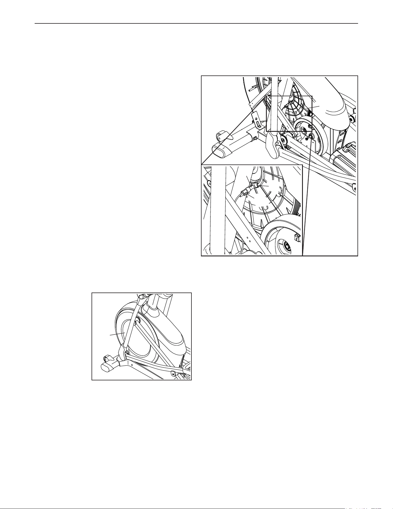
HOWTOADJUSTTHEREEDSWITCH
If the console does not display correct feedback, the
reed switch should be adjusted. To adjust the drive
belt, first unplugthepoweradapter.
Next, use
a standard
screwdriver to
pry off the left
Disc (71).
Note: For clarity, the left shield is shown removed in the
drawing at the right.
Then, locate the Reed Switch (38). Turn the Pulley (19)
until a Magnet (43) is aligned with the Reed Switch.
Slightly loosen the indicated M4 x 16mm Screw (101).
Slide the Reed Switch (38) slightly closer to or away
from the Magnet (43), and then retighten the Screw.
Then, plug in the power adapter and rock the Pulley
(19) forward and backward just enough that the
Magnet (43) passes the Reed Switch (38) repeatedly.
Repeat these actions until the console displays correct
feedback.
When the reed switch is correctly adjusted, reattach
the left disc and plug in the power adapter.
71
38
19
101
43
MAINTENANCEANDTROUBLESHOOTING
31
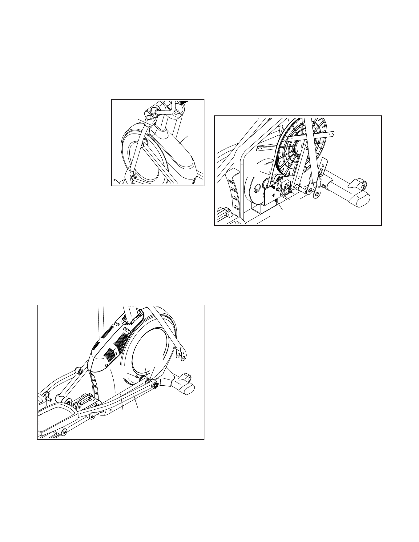
HOWTOADJUSTTHEDRIVEBELT
If the pedals slip while you are pedaling, even while
the resistance is adjusted to the highest level, the drive
belt may need to be adjusted.
To adjust the drive belt, first unplugthepower
adapter.
Next, use
a standard
screwdriver to pry
off the Shield Cover
(75) and the Shield
Cover Cap (118).
Seeassemblystep15onpage15. Remove the
Right Leg Outer and Inner Covers (69, 83).
Seeassemblystep12onpage13. Remove the
Right Pedal Arm (58) from the Right Upper Body
Leg (60).
Next, remove the M8 x 16mm Screw (95), the Large
Axle Cover (53), and the M8 Washer (not shown) from
the right Crank Arm (20). Then, carefully remove the
Right Roller Arm (59) and the Right Pedal Arm (58)
from the elliptical.
SeeEXPLODEDDRAWINGConpage39.
Identify the Left and Right Shields (73, 74). Remove
the M4 x 19mm Screws (5), the M4 x 25mm Screws
(124), and the M4 x 48mm Screw (107) from the Left
and Right Shields; makesuretonotethelocationof
eachsizeofScrew. Then, remove the Right Shield.
Next, locate and loosen the Idler Screw (89). Next,
tighten the Belt Adjustment Screw (91) until the Drive
Belt (113) is tight. Then, retighten the Idler Screw.
Reattach the parts that you removed. Then, plug in the
power adapter.
75
118
59
20
95
58
53
113
91
89
32
EXERCISEGUIDELINES
These guidelines will help you to plan your exercise
program. For detailed exercise information, obtain a
reputable book or consult your physician. Remember,
proper nutrition and adequate rest are essential for
successful results.
EXERCISEINTENSITY
Whether your goal is to burn fat or to strengthen your
cardiovascular system, exercising at the proper inten-
sity is the key to achieving results. You can use your
heart rate as a guide to find the proper intensity level.
The chart below shows recommended heart rates for
fat burning and aerobic exercise.
To find the proper intensity level, find your age at the
bottom of the chart (ages are rounded off to the near-
est ten years). The three numbers listed above your
age define your “training zone.” The lowest number is
the heart rate for fat burning, the middle number is the
heart rate for maximum fat burning, and the highest
number is the heart rate for aerobic exercise.
BurningFat—To burn fat effectively, you must exer-
cise at a low intensity level for a sustained period of
time. During the first few minutes of exercise, your
body uses carbohydrate calories for energy. Only after
the first few minutes of exercise does your body begin
to use stored fat calories for energy. If your goal is to
burn fat, adjust the intensity of your exercise until your
heart rate is near the lowest number in your training
zone. For maximum fat burning, exercise with your
heart rate near the middle number in your training
zone.
AerobicExercise—If your goal is to strengthen your
cardiovascular system, you must perform aerobic
exercise, which is activity that requires large amounts
of oxygen for prolonged periods of time. For aerobic
exercise, adjust the intensity of your exercise until your
heart rate is near the highest number in your training
zone.
WORKOUTGUIDELINES
WarmingUp—Start with 5 to 10 minutes of stretch-
ing and light exercise. A warm-up increases your body
temperature, heart rate, and circulation in preparation
for exercise.
TrainingZoneExercise—Exercise for 20 to 30 min-
utes with your heart rate in your training zone. (During
the first few weeks of your exercise program, do not
keep your heart rate in your training zone for longer
than 20 minutes.) Breathe regularly and deeply as you
exercise; never hold your breath.
CoolingDown—Finish with 5 to 10 minutes of stretch-
ing. Stretching increases the flexibility of your muscles
and helps to prevent post-exercise problems.
EXERCISEFREQUENCY
To maintain or improve your condition, complete three
workouts each week, with at least one day of rest
between workouts. After a few months of regular exer-
cise, you may complete up to five workouts each week,
if desired. Remember, the key to success is to make
exercise a regular and enjoyable part of your everyday
life.
WARNING:
Beforebeginningthis
oranyexerciseprogram,consultyourphysi-
cian.Thisisespeciallyimportantforpersons
overage35orpersonswithpre-existing
healthproblems.
Theheartratemonitorisnotamedicaldevice.
Variousfactorsmayaffecttheaccuracyof
heartratereadings.Theheartratemonitoris
intendedonlyasanexerciseaidindetermin-
ingheartratetrendsingeneral.
33
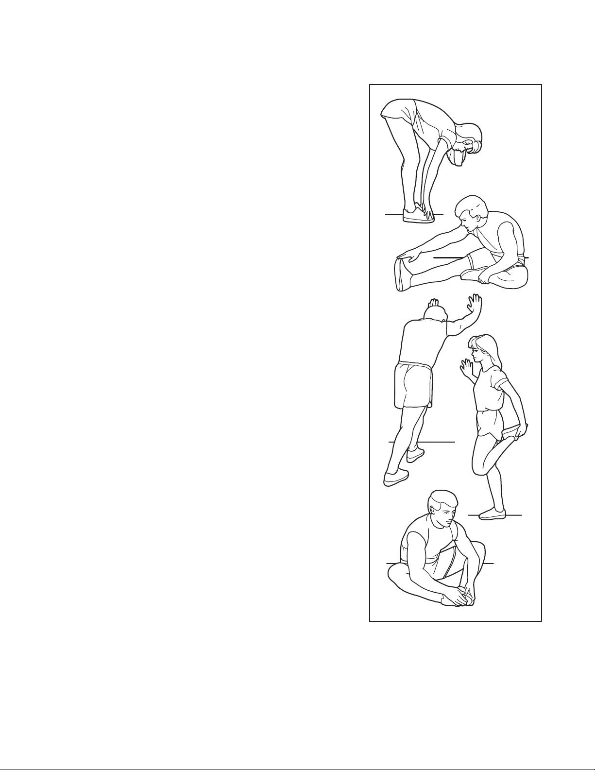
SUGGESTEDSTRETCHES
The correct form for several basic stretches is shown at the right. Move slowly as you stretch; never bounce.
1.ToeTouchStretch
Stand with your knees bent slightly and slowly bend forward from
your hips. Allow your back and shoulders to relax as you reach down
toward your toes as far as possible. Hold for 15 counts, then relax.
Repeat 3 times. Stretches: Hamstrings, back of knees and back.
2.HamstringStretch
Sit with one leg extended. Bring the sole of the opposite foot toward
you and rest it against the inner thigh of your extended leg. Reach
toward your toes as far as possible. Hold for 15 counts, then relax.
Repeat 3 times for each leg. Stretches: Hamstrings, lower back and
groin.
3.Calf/AchillesStretch
With one leg in front of the other, reach forward and place your hands
against a wall. Keep your back leg straight and your back foot flat
on the floor. Bend your front leg, lean forward and move your hips
toward the wall. Hold for 15 counts, then relax. Repeat 3 times for
each leg. To cause further stretching of the achilles tendons, bend
your back leg as well. Stretches: Calves, achilles tendons and ankles.
4.QuadricepsStretch
With one hand against a wall for balance, reach back and grasp one
foot with your other hand. Bring your heel as close to your buttocks
as possible. Hold for 15 counts, then relax. Repeat 3 times for each
leg. Stretches: Quadriceps and hip muscles.
5.InnerThighStretch
Sit with the soles of your feet together and your knees outward.
Pull your feet toward your groin area as far as possible. Hold for 15
counts, then relax. Repeat 3 times. Stretches: Quadriceps and hip
muscles.
1
2
3
4
5

34
NOTES

35
1 1 Frame
2 1 Rear Stabilizer
3 1 Ramp
4 1 Upright
5 6 M4 x 19mm Screw
6 1 Front Stabilizer
7 1 Console
8 2 Roller Guide
9 4 #8 x 12mm Screw
10 1 Ramp Cover
11 1 Left Latch Handle
12 1 Right Latch Handle
13 1 Latch Button
14 1 Latch Bracket
15 1 Rear Stabilizer Cover
16 2 Track
17 1 Latch Pin
18 1 Crank
19 1 Pulley
20 2 Crank Arm
21 4 M4 x 10mm Screw
22 1 Idler
23 3 Bumper
24 1 Small Leveling Foot
25 1 Resistance Motor
26 4 M10 Locknut
27 2 M10 Washer
28 1 Eddy Mechanism
29 1 Mechanism Axle
30 4 Stabilizer Cap
31 2 M10 x 19mm Screw
32 2 M5 Washer
33 2 Leveling Foot
34 2 Wheel
35 1 Pivot Axle
36 2 Upright Bushing
37 1 Accessory Tray
38 1 Reed Switch/Wire
39 1 Reed Switch Clamp
40 2 Frame Bearing
41 1 Mechanism Snap Ring
42 1 Sleeve
43 2 Magnet
44 1 Left Pedal Arm
45 1 Left Roller Arm
46 1 Left Upper Body Leg
47 1 Left Upper Body Arm
48 1 Ramp Spring
49 2 Pedal
50 6 Frame Bushing
51 2 Roller
52 2 Pedal Arm Rear Cap
53 4 Large Axle Cover
54 2 16mm Wave Washer
55 2 Small Axle Cover
56 4 Roller Arm Bushing
57 6 Large Arm Bearing
58 1 Right Pedal Arm
59 1 Right Roller Arm
60 1 Right Upper Body Leg
61 1 Right Upper Body Arm
62 2 Grip
63 2 Pulse Sensor/Wire
64 2 Pedal Arm Axle
65 1 Right Arm Front Cover
66 1 Right Arm Rear Cover
67 1 Left Arm Front Cover
68 1 Left Arm Rear Cover
69 1 Right Leg Outer Cover
70 1 Left Leg Outer Cover
71 2 Disc
72 1 Left Leg Inner Cover
73 1 Left Shield
74 1 Right Shield
75 1 Shield Cover
76 1 Left Pedal Arm Side Cap
77 4 Axle Spacer
78 2 Key
79 1 Front Console Cover
80 1 Rear Console Cover
81 1 Rear Upright Cover
82 10 M8 x 13mm Screw
83 1 Right Leg Inner Cover
84 1 Ramp Axle
85 2 M4 x 14mm Screw
86 2 M10 x 58mm Bolt
87 1 Right Pedal Arm Side Cap
88 1 Idler Pivot Screw
89 1 Idler Screw
90 2 M6 Washer
91 1 Belt Adjustment Screw
92 4 M10 x 25mm Screw
93 4 M4 x 12mm Screw
94 2 M4 Nut
95 8 M8 x 16mm Screw
96 4 M8 x 38mm Bolt
97 10 M8 Washer
98 2 M8 x 18mm Washer
99 1 Plastic Spacer
100 4 Leg Bearing
KeyNo. Qty. Description KeyNo. Qty. Description
PARTLIST
Model No. PFEL55914.4 R0416A

36
101 36 M4 x 16mm Screw
102 6 M8 Locknut
103 8 M6 x 12mm Screw
104 4 M10 x 122mm Screw
105 8 M10 Split Washer
106 3 Cover Mount
107 1 M4 x 48mm Screw
108 2 M6 x 13mm Screw
109 2 M10 x 60mm Bolt
110 1 Upper Wire
111 1 Lower Wire
112 3 M4 x 19mm Self-tapping Screw
113 1 Drive Belt
114 4 M4 x 42mm Screw
115 2 M4 x 30mm Screw
116 2 Disc Ring
117 1 Front Upright Cover
118 1 Shield Cover Cap
119 1 Power Adapter
120 2 M8 x 14mm Shoulder Screw
121 1 Tablet Holder
122 2 M4 x 35mm Screw
123 2 M4 x 16mm Machine Screw
124 2 M4 x 25mm Screw
125 2 Small Arm Bearing
126 1 Pin Spring
* – Assembly Tool
* – Grease Packet
* – User’sManual
KeyNo. Qty. Description KeyNo. Qty. Description
Note: Specifications are subject to change without notice. For information about ordering replacement parts, see
the back cover of this manual. *These parts are not illustrated.
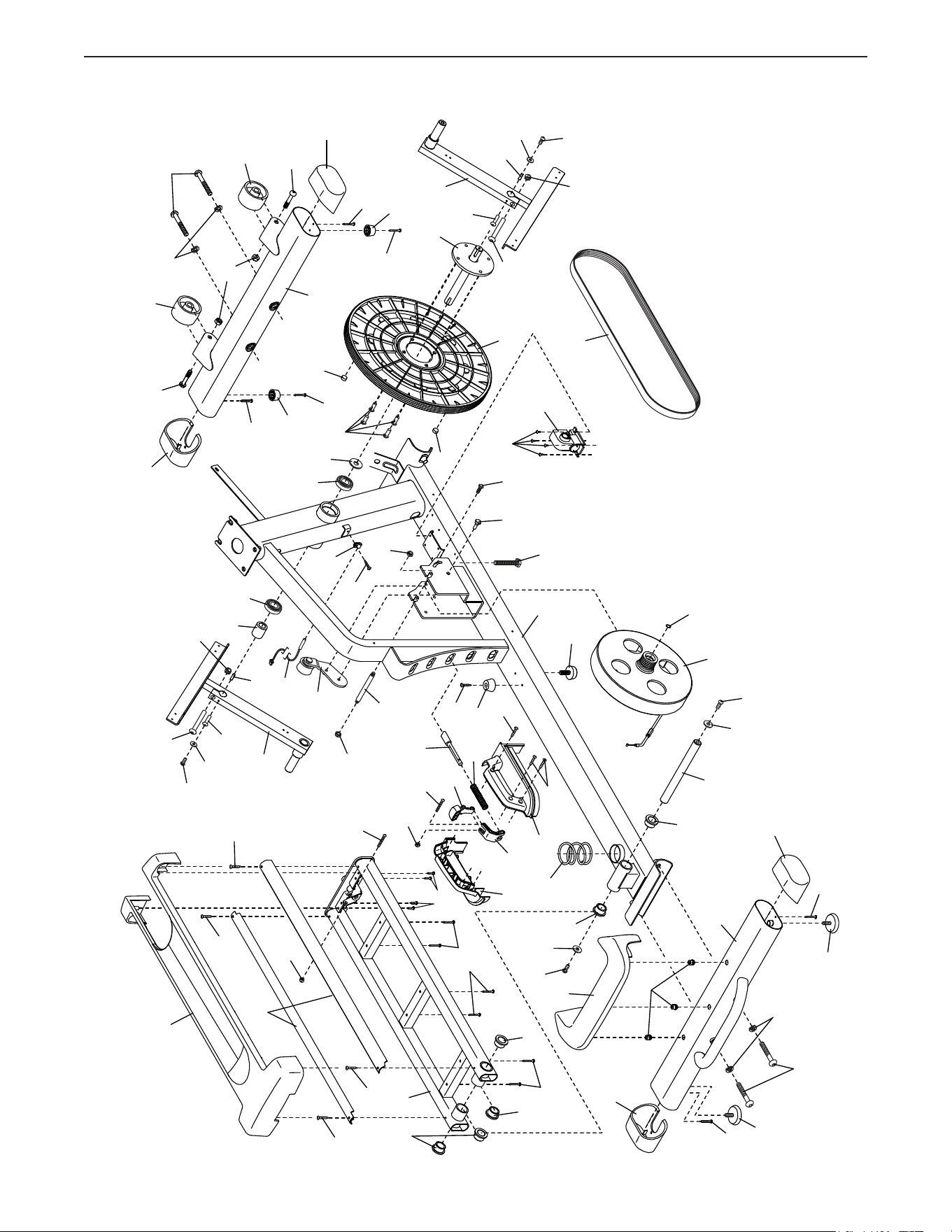
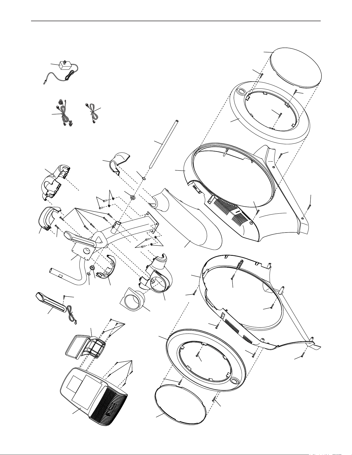
37
EXPLODEDDRAWINGA
1
3
6
10
12
101
101
2
11
14
16
18
19
13
15
106
20
20
21
21
122
21
21
94
94
28
30
30
22
29
34
34
38
39
33
33
40
40
41
24
112
23
43
23
112
112
23
43
48
42
82
101
78
78
86
86
88
85
85
31
31
89
90
90
91
27
27
105
105
26
26
102
104
104
101
101
101
101
108
108
26
109
109
113
84
50
50
50
50
50
115
115
102
30
30
114
101
93
25
99
17
126
Model No. PFEL55914.4 R0416A
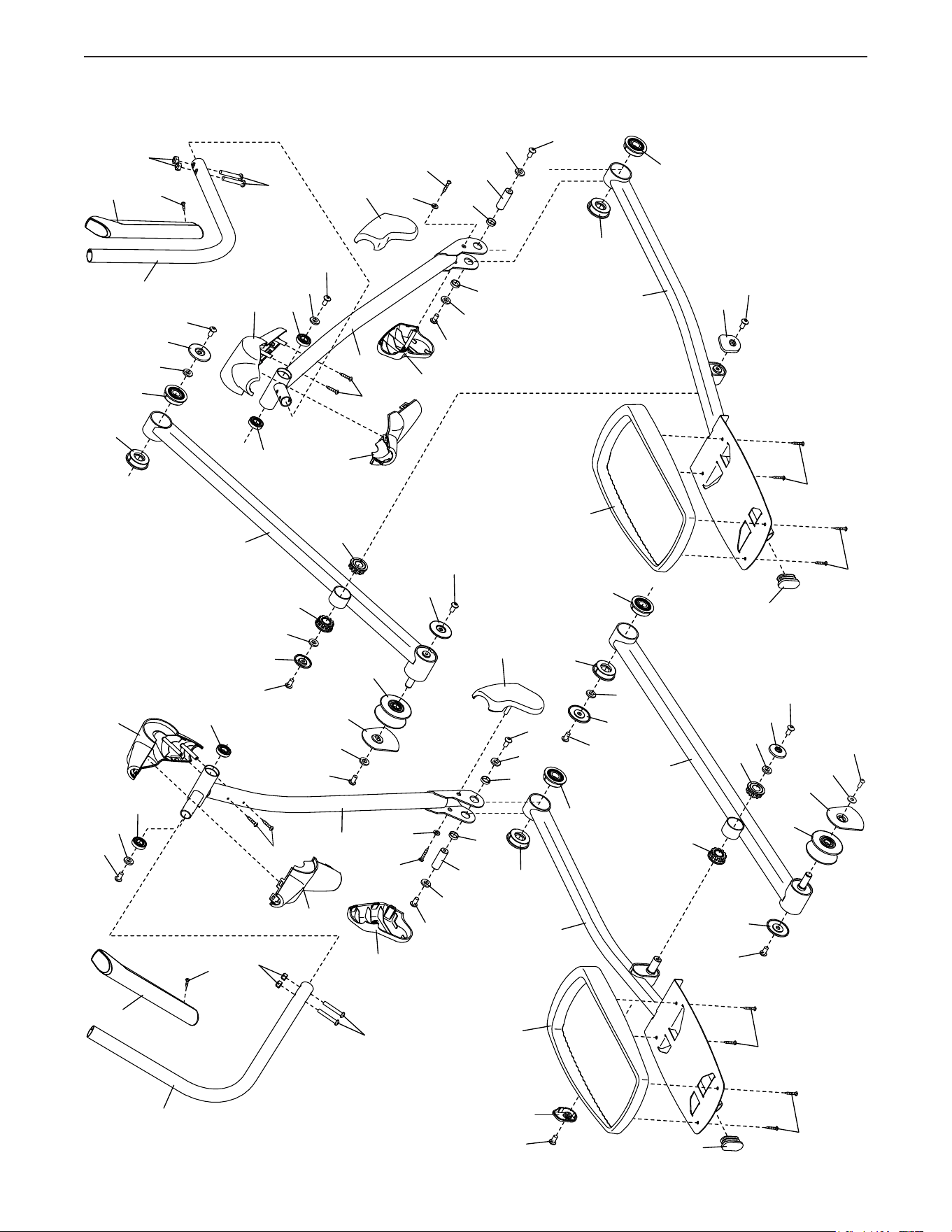
38
EXPLODEDDRAWINGB
46
52
52
45
44
47
49
49
51
51
56
56
56
56
58
59
53
53
53
53
55
55
57
57
57
57
125
57
57
60
101
6
2
66
68
101
62
61
64
64
65
67
70
72
69
32
32
83
87
76
77
77
77
101
101
77
95
95
95
95
95
95
82
120
82
120
82
82
82
82
96
96
98
98
97
97
125
97
97
97
97
97
97
97
97
100
100
100
100
101
101
103
102
102
8
95
95
8
103
103
103
Model No. PFEL55914.4 R0416A
39
EXPLODEDDRAWINGC
4
36
36
35
37
81
54
54
63
71
71
74
79
73
75
80
101
105
105
92
92
123
101
101
5
124
5
107
101
123
101
124
5
5
5
5
101
101
101
9
121
110
119
118
116
116
117
111
7
Model No. PFEL55914.4 R0416A

Part No. 381245 R0416A Printed in China © 2016 ICON Health & Fitness, Inc.
To order replacement parts, please see the front cover of this manual. To help us assist you, be prepared to
provide the following information when contacting us:
• the model number and serial number of the product (see the front cover of this manual)
• the name of the product (see the front cover of this manual)
• the key number and description of the replacement part(s) (see the PART LIST and the EXPLODED DRAWING
near the end of this manual)
ORDERINGREPLACEMENTPARTS
ICON Health & Fitness, Inc. (ICON) warrants this product to be free from defects in workmanship and
material, under normal use and service conditions. The frame is warranted for the lifetime of the original
purchaser (customer). Parts and labor are warranted for one (1) year from the date of purchase.
Thiswarrantyextendsonlytotheoriginalpurchaser(customer).ICON’sobligationunderthiswarrantyis
limitedtorepairingorreplacing,atICON’soption,theproductthroughoneofitsauthorizedservicecenters.
All repairs for which warranty claims are made must be preauthorized by ICON. If the product is shipped
toaservicecenter,freightchargestoandfromtheservicecenterwillbethecustomer’sresponsibility.If
replacement parts are shipped while the product is under warranty, the customer will be responsible for a
minimal handling charge. For in-home service, the customer will be responsible for a minimal trip charge.
This warranty does not extend to freight damage to the product. This warranty will automatically be voided
if the product is used as a store display model, if the product is purchased or transported outside the USA,
if all instructions in this manual are not followed, if the product is abused or improperly or abnormally used,
oriftheproductisusedforcommercialorrentalpurposes.Nootherwarrantybeyondthatspeci�callyset
forth above is authorized by ICON.
ICON is not responsible or liable for indirect, special, or consequential damages arising out of or in con-
nection with the use or performance of the product; damages with respect to any economic loss, loss of
property,lossofrevenuesorpro�ts,lossofenjoymentoruse,orcostsofremovalorinstallation;orother
consequential damages of any kind. Some states do not allow the exclusion or limitation of incidental or
consequential damages. Accordingly, the above limitation may not apply to the customer.
The warranty extended hereunder is in lieu of any and all other warranties, and any implied warranties of
merchantabilityor�tnessforaparticularpurposearelimitedintheirscopeanddurationtothetermsset
forth herein. Some states do not allow limitations on how long an implied warranty lasts. Accordingly, the
above limitation may not apply to the customer.
Thiswarrantyprovidesspeci�clegalrights;thecustomermayhaveotherrightsthatvaryfromstatetostate.
ICONHealth&Fitness,Inc.,1500S.1000W.,Logan,UT84321-9813
LIMITEDWARRANTY
IMPORTANT:Toprotectyourfitnessequipmentwithanextendedserviceplan,seepage5.