Ca rd ioCrossTra i her 8 2 0
Model No. 831.283520
Serial No.
Write the serialnumber in the
space above for reference.
Serial
Number
Decal
• Assembly
• Operation
• Maintenance
• Part List and Drawing
A CAUTION
Read all precautions and instruc-
tions in this manual before using
this equipment. Keep this manu-
al for future reference.
ELLIPTICAL EXERCISER
User's Manual
Patent Pending
Sears, Roebuck and Co., Hoffman Estates, IL 60179
Ca rd ioC rossTrai net8 2 0
TABLE OF CONTENTS
IMPORTANT PRECAUTIONS ............................................................. 3
BEFORE YOU BEGIN ................................................................... 4
ASSEMBLY ........................................................................... 5
HOW TO USE THE ELLIPTICAL CROSSTRAINER ............................................. 9
MAINTENANCE AND TROUBLESHOOTING ................................................. 20
CONDITIONING GUIDELINES ............................................................ 21
PART LIST ........................................................................... 22
EXPLODED DRAWING ................................................................. 23
HOW TO ORDER REPLACEMENT PARTS ........................................... Back Cover
FULL 90 DAYWARRANTY ....................................................... Back Cover
2
IMPORTANT PRECAUTIONS
WARNING: To reduce the risk of serious injury, read the following important precau-
tions before using the elliptical crosstrainer.
1. Read all instructions in this manual before
using the elliptical crosstrainer.
2. It is the responsibility of the owner to ensure
that all users of the elliptical crosstrainer
are adequately informed of all precautions.
heart rate readings. The pulse sensor is
intended only as an exercise aid in determin-
ing heart rate trends in general.
11. Keep your back straight when using the ellip-
tical crosstrainer; do not arch your back.
3. The elliptical crosstreiner is intended for
home use only. Do not use the elliptical
crosstrainer in a commercial, rental, or insti-
tutlonal setting.
4. Place the elliptical crosstrainer on a level
surface, with a mat beneath it to protect the
floor or carpet. Keep the elliptical crosstrain-
el" indoors, away from moisture and dust.
5. Inspect and properly tighten all parts regu-
larly, Replace any worn parts immediately.
6. Keep children under 12 and pets away from
the elliptical crosstrainer at all times.
7. The elliptical crosstralner should not be used
by persons weighing more than 250 pounds.
8. Wear appropriate exercise clothes when
using the elliptical crosstralner. Always wear
athletic shoos for foot protection while exer-
cising.
9. Hold the handgrip pulse sensor or the han-
dlebars when mounting, dismounting, or
using the elliptical crosstrainer.
10. The pulse sensor is not a medical device.
Various factors may affect the accuracy of
12. If you feel pain or dizziness while exercis-
ing, stop immediately and begin cooling
down.
13.When you stop exercising, allow the pedals
to slowly come to a stop.
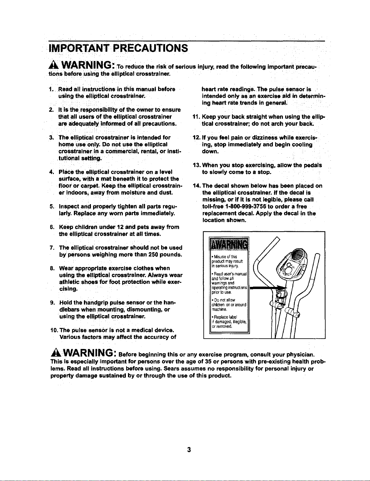
14. The decal shown below has been placed on
the elliptical crosstrainer. If the decal is
missing, or if it is not legible, please call
toll-free 1-800-999-3756 to order a free
replacement decal. Apply the decal in the
location shown.
, Misuseofthis
pro_uclmayresun
nsehousinjury.
, Readuser'smanua
andfollow all
warningsand
opera_bngIrl$[ruct_oqs
priortOuse,
• Do not allow
_lldren on craround
machine
• ReplaCelabel
d damaged, illegible
or renlOVeO
WARNING: Before beginning this or any exercise program, consult your physician.
This is especially important for persons over the age of 35 or persons with pre-existing health prob-
lems. Read all instructions before using. Sears assumes no responsibility for personal injury or
property damage sustained by or through the use of this product.
3
BEFORE YOU BEGIN
Congratulations for selecting the new PROFORM ®
820 CARDIO CROSSTRAINER. The PROFORM®820
is an incredibly smooth exerciser that moves your feet
in a natural elliptical path, minimizing the impact on
your knees and ankles. And the unique PROFORM ®
820 features adjustable resistance and a state-of-the-
art console to help you get the most from your
exercise.
For your benefit, read this manual carefully before
you use the elliptical crosstrainer. If you have
questions after reading this manual, call 1-800-4-MY-
HOME®(1-800-4694663). To help us assist you,
please note the product model number and serial
number before calling. The model number is
831.283520. The serial number can be found on a
decal attached to the elliptical crosstrainer (see the
front cover of this manual for the location of the decal).
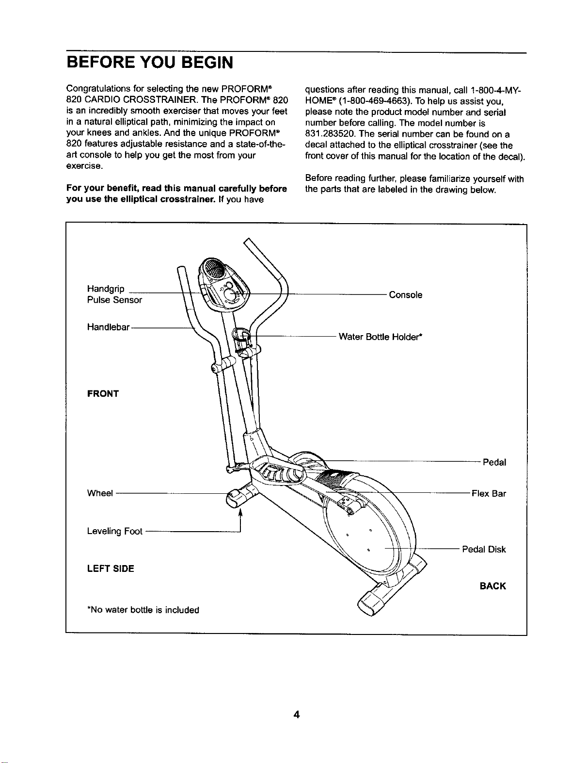
Beforereading further, please familiarize yourself with
the parts that are labeled in the drawing below.
Handgrip
Pulse Sensor
Console
Handlebar
Water BottleHolder*
FRONT
Pedal
Wheel Flex Bar
LevelingFoot
LEFT SIDE
PedalDisk
BACK
*No water bottle is included
4
ASSEMBLY
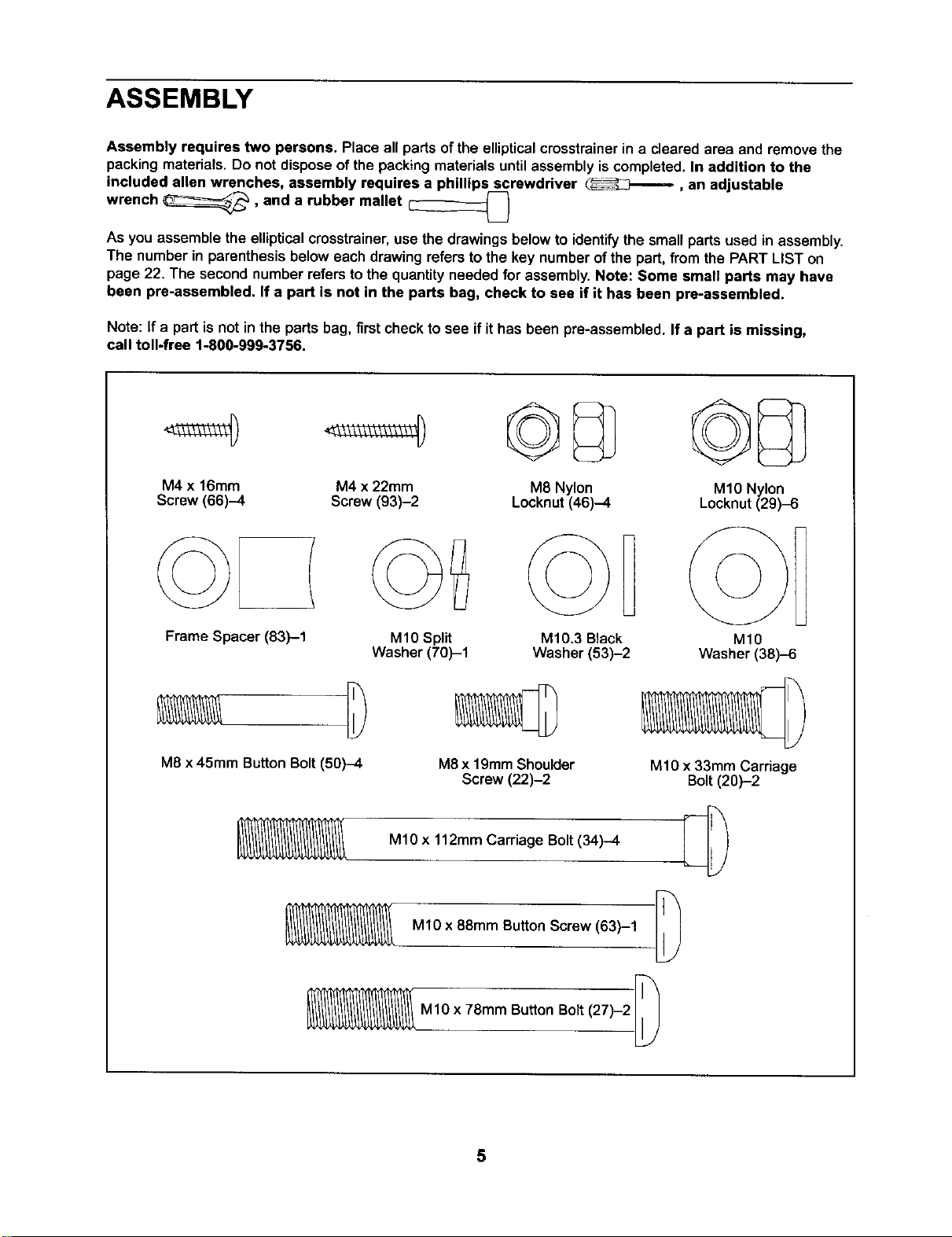
Assembly requires two persons. Place all parts ofthe ellipticalcrosstrainerin a clearedarea and remove the
packingmaterials. Do not disposeof the packing materialsuntilassembly iscompleted. In addition to the
included allen wrenches, assembly requires a phillips screwdriver
wrench _, and a rubber mallet _ , an adjustable
U
As you assemble the ellipticalcmsstrainer,use the drawings below to identifythe small parts used in assembly.
The number in parenthesisbelow each drawingrefers tothe key numberof the part,from the PART LIST on
page 22. The secondnumber refers to the quantityneeded for assembly.Note: Some small parts may have
been pre-assembled. If a part is not in the parts bag, check to see if it has been pre-assembled.
Note: If a part isnot inthe parts bag, first check to see ifit has been pre-assembled. If a part is missing,
call toll-free 1-800-999-3756.
M4 x 16mm M4 x 22mm M8 Nylon
Screw (66)-4 Screw (93)-2 Locknut(46)-4
Frame Spacer (83)--1
M10 Split
Washer (70)-1
M8 x 45mm ButtonBolt(50)-4
©B
M10.3 Black
Washer (53)-2
M8x 19mmShoulder
Screw (22)-2
MlO x 112mm Carriage Bolt(34)-4
MlO x 88mm Button Screw (63)-1
M1Ox 78mm ButtonBolt(27)-2
MIO Nylon
Locknut(29).6
MlO
Washer (38)-6
MIO x 33mm Carnage
Bolt(20)-2
5
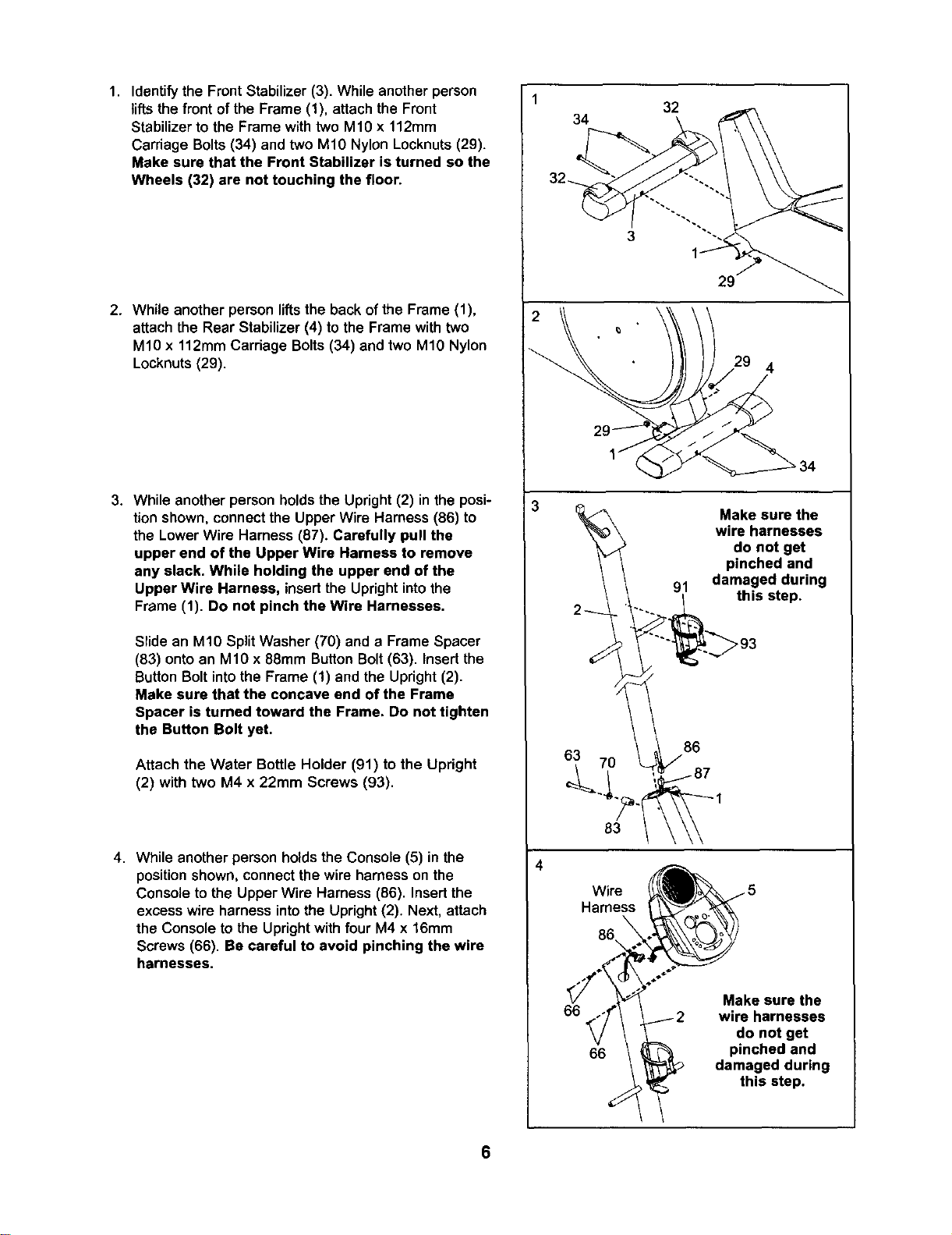
1. Identify the Front Stabilizer (3). While anotherperson
lifts the front of the Frame (1), attach the Front
Stabilizer to the Frame with two M10 x 112mm
Carriage Bolts (34) and two M10 Nylon Locknuts (29).
Make sure that the Front Stabilizer is turned so the
Wheels (32) are not touching the floor.
2. While another person lifts the back of the Frame (1),
attach the Rear Stabilizer (4) to the Frame with two
M10 x 112mm Carriage Bolts (34) and two M10 Nylon
Locknuts (29).
3. While another person holds the Upright (2) in the posi-
tion shown, connect the Upper Wire Harness (86) to
the Lower Wire Harness (87). Carefully pull the
upper end of the Upper Wire Harness to remove
any slack. While holding the upper end of the
Upper Wire Harness, insertthe Uprightintothe
Frame (1). Do not pinch the Wire Harnesses.
Slide an M10 Split Washer (70) and a Frame Spacer
(83) onto an M10 x 88ram Button Bolt (63). Insert the
Button Bolt into the Frame (1) and the Upright (2).
Make sure that the concave end of the Frame
Spacer is turned toward the Frame. Do not tighten
the Button Bolt yet,
Attach the Water Bottle Holder (91) to the Upright
(2) with two M4 x 22mm Screws (93).
4. While another person holds the Console (5) in the
position shown, connect the wire harness on the
Console to the Upper Wire Harness (86). Insert the
excess wire harness into the Upright (2). Next, attach
the Console to the Upright with four M4 x 16mm
Screws (66). Be careful to avoid pinching the wire
harnesses.
2
32
34
3
29
4
2I
63 70
Make sure the
wire harnesses
do not get
pinched and
91 damaged during
_._ this step.
Wire
Harness
86
66
66
Make sure the
wire harnesses
do not get
pinched and
damaged during
this step.
6
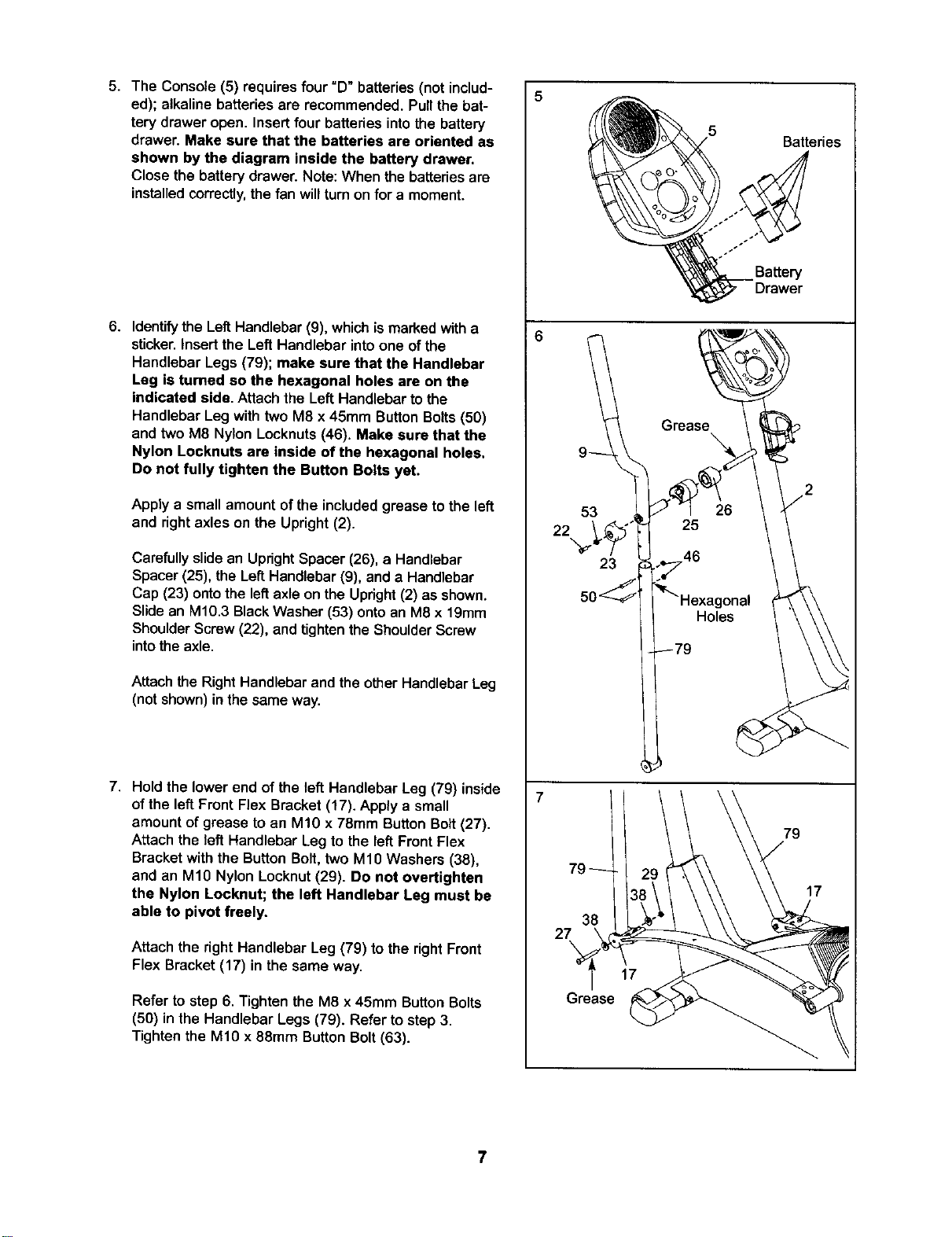
5. The Console (5) requires four "D" batteries (not includ-
ed); alkaline batteries are recommended. Pull the bat-
tery drawer open. Insert four batteries into the battery
drawer. Make sure that the batteries are oriented as
shown by the diagram inside the battery drawer.
Close the battery drawer. Note: When the batteriesare
installedcorrectly,thefan willturnonfor a moment.
6. Identify the LeftHandlebar(9), whichis marked witha
sticker. Insert the Left Handlebar into one of the
Handlebar Legs (79); make sure that the Handlebar
Leg is turned so the hexagonal holes are on the
indicated side, Attach the Left Handlebarto the
Handlebar Leg with two M8 x 45mm ButtonBolts(50)
and two M8 Nylon Locknuts(46). Make sure that the
Nylon Locknuts are inside of the hexagonal holes.
Do not fully tighten the Button Bolts yet.
Apply a small amount of the included grease to the left
and right axles on the Upright (2).
Carefully slide an UprightSpacer (26), a Handlebar
Spacer (25), the Left Handlebar (9), and a Handlebar
Cap (23) onto the left axle on the Upright (2) as shown.
Slide an M10.3 Black Washer (53) onto an M8 x 19mm
Shoulder Screw (22), and tighten the Shoulder Screw
into the axle.
Attach the RightHandlebar and the otherHandlebar Leg
(not shown) in the same way.
7. Hold the lower end of the left Handlebar Leg (79) inside
of the left Front Flex Bracket (17). Apply a small
amount of grease to an M10 x 78mm Button Bolt (27).
Attach the left Handlebar Leg to the left Front Flex
Bracket with the Button Bolt, two M10 Washers (38),
and an M10 Nylon Locknut (29). Do not overtighten
the Nylon Locknut; the left Handlebar Leg must be
able to pivot freely.
Attach the right Handlebar Leg (79) to the right Front
Flex Bracket (17) in the same way.
Refer to step 6. Tighten the M8 x 45mm Button Bolts
(50) in the Handlebar Legs (79). Refer to step 3.
Tighten the M10 x 88mm Button Bolt (63).
53
22
23
38
27
Grease
Batteries
Battery
Drawer
79
17
7
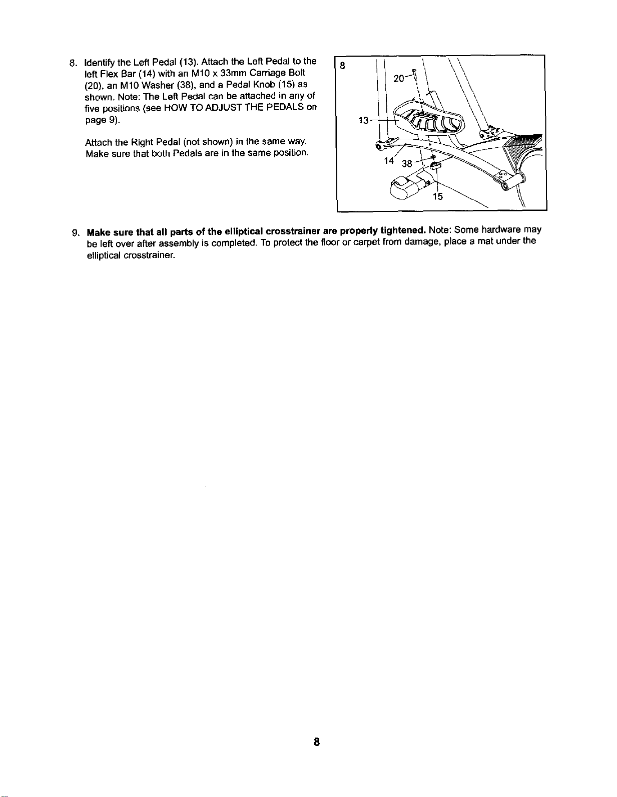
8. Identify the Left Pedal (13). Attach the Left Pedal to the
left Flex Bar (14) with an M10 x 33mm Carriage Bolt
(20), an M10 Washer (38), and a Pedal Knob (15) as
shown. Note: The Left Pedal can be attached in any of
five positions (see HOW TO ADJUST THE PEDALS on
page 9).
Attach the Right Pedal (not shown) in the same way.
Make sure that both Pedals are in the same position.
14
15
9. Make sure that all parts of the elliptical crosstrainer are properly tightened. Note: Some hardware may
be leftover afterassembly is completed.To protectthe floor or carpet from damage, place a mat underthe
ellipticalcrosstrainer.
8
HOW TO USE THE ELLIPTICAL CROSSTRAINER
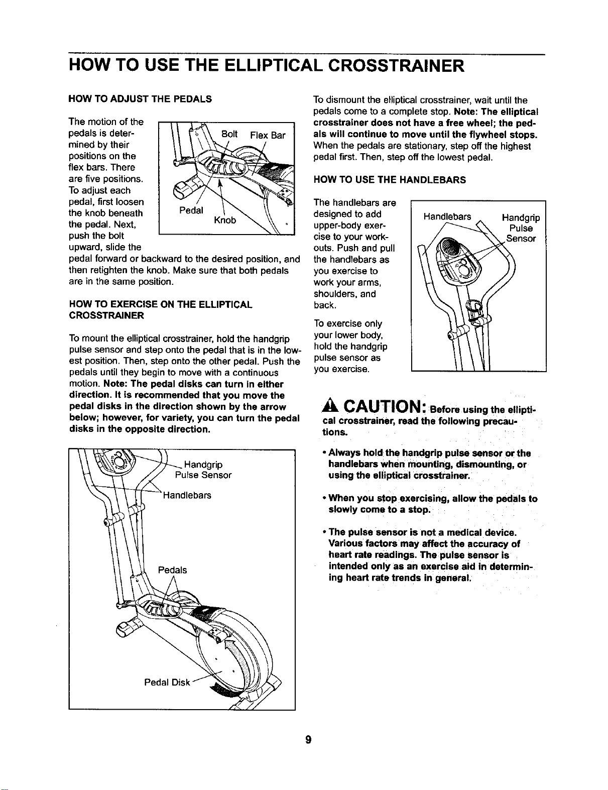
HOW TO ADJUST THE PEDALS
The motionof the
pedals is deter-
mined by their
positions on the
flex bars. There
are five positions.
To adjust each
pedal, first loosen
the knob beneath
the pedal. Next,
push the bolt
upward, slide the
leI Bar
..... Krlob _ _,
pedal forward or backward to the desired position, and
then retighten the knob. Make sure that both pedals
are in the same position.
HOW TO EXERCISE ON THE ELLIPTICAL
CROSSTRAINER
To mount the elliptical crosstrainer, hold the handgrip
pulse sensor and step onto the pedal that is in the low-
est position. Then, step onto the other pedal. Push the
pedals until they begin to move with a continuous
motion Note: The pedal disks can turn in either
direction. It is recommended that you move the
pedal disks in the direction shown by the arrow
below; however, for variety, you can turn the pedal
disks in the opposite direction.
I _ Handgrip
Pulse Sensor
I -- Handlebars
Pedals
To dismount the ellipticalcmsstrainer, wait untilthe
pedalscome to a completestop. Note: The elliptical
crosstrainer does not have a free wheel; the ped-
als will continue to move until the flywheel stops.
When the pedals are stationary,step offthe highest
pedalfirst. Then, step offthe lowest pedal.
HOW TO USE THE HANDLEBARS
The handlebars are
designed to add
upper-bodyexer-
cise to your work-
outs. Push and pull
the handlebars as
you exercise to
work your arms,
shoulders, and
back.
To exercise only
your lower body,
hold the handgrip
pulse sensor as
you exercise.
Handlebars Handgrip
Pulse
neot
CAUTION: Before using the ellipti-
cal crosstrainer, read the following precau-
tions.
• Always hold the handgrip pulse sensor or the
handlebars when mounting, dismounting, or
using the elliptical crosstrainer
• When you stop exercising, allow the pedals to
slowly come to a stop.
• The pulse sensor is not a medical device.
Various factors may affect the accuracy of
heart rate readings. The pulse sensor is
intended only as an exercise aid in determin-
ing heart rate trends in general.
9
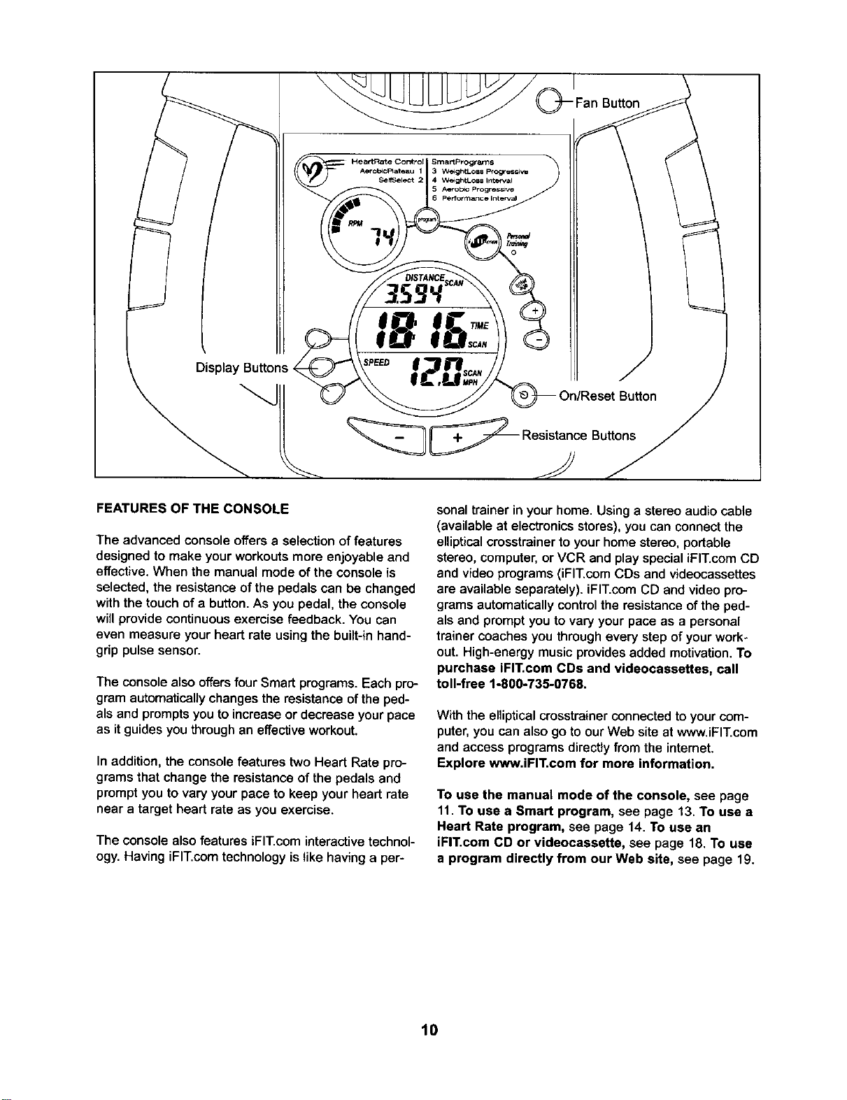
Display Buttons
;8
;PEED
__ Resistance Buttons
FEATURES OF THE CONSOLE
The advanced console offers a selection of features
designed to make your workouts more enjoyable and
effective. When the manual mode of the console is
selected, the resistance of the pedals can be changed
with the touch of a button. As you pedal, the console
will provide continuous exercise feedback. You can
even measure your heart rate using the built-in hand-
grip pulse sensor.
The console also offers four Smart programs. Each pro-
gram automatically changesthe resistance of the ped-
als and prompts you to increase or decrease your pace
as it guides you through an effective workout.
In addition, the console features two Heart Rate pro-
grams that change the resistance of the pedals and
prompt you to vary your pace to keep your heart rate
near a target heart rate as you exercise.
The console also features iFIT.com interactive technol-
ogy. Having iFIT.com technology is like having a per-
sonal trainer in your home. Using a stereo audio cable
(available at electronics stores), you can connect the
elliptical crosstrainer to your home stereo, portable
stereo, computer, or VCR and play special iFIT.com CD
and video programs (iFIT.com CDs and videocassettes
are available separately), iFIT.com CD and video pro-
grams automatically control the resistance of the ped-
als and prompt you to vary your pace as a personal
trainer coaches you through every step of your work-
out. High-energy music provides added motivation. To
purchase iFIT.com CDs and videocassettes, call
toll-free 1-800-735-0768.
With the elliptical crosstrainer connected to your com-
puter, you can also go to our Web site at www.iFIT.com
and access programs directly from the intemet.
Explore www.iFIT.com for more information.
To use the manual mode of the console, see page
11. To use a Smart program, see page 13. To use a
Heart Rate program, see page 14. To use an
iFIT.com CD or videocassette, see page 18. To use
a program directly from our Web site, see page 19.
10
HOW 1"O USE THE MANUAL MODE
i]
19
Turn on the console.
Note: The console requires four 1.5V "D" battedes
(see assembly step 5 on page 7).
Totum on the console, press the On/Reset button
or begin pedaling. (See the drawing on page 11 to
identify the On/Reset button.)
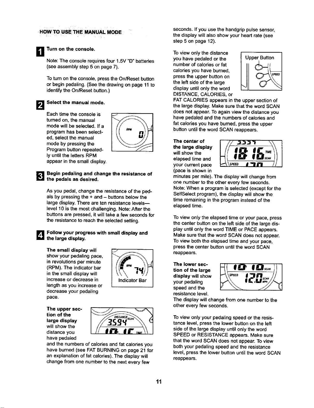
Select the manual mode.
Each time the console is
turned on, the manual
mode will be selected. If a
program has been select-
ed, select the manual
mode by pressing the
Program button repeated-
ly until the letters RPM
appear in the small display.
_1 Begin pedaling and change the resistance of
the pedals as desired.
As you pedal, change the resistance of the ped-
als by pressing the + and - buttons below the
large display. There are ten resistance levels--
level 10 is the most challenging. Note: After the
buttons are pressed, it will take a few seconds for
the resistance to reach the selected setting.
D Follow your progress with small display and
the large display.
The small display will
show your pedaling pace,
in revolutions per minute
(RPM). The indicator bar
in the small display will
increase or decrease in
length as you increase or
decrease your pedaling
pace.
J
Indicator Bar
The upper sec-
tion of the
large display
will show the
distance you
have pedaled
and the numbers of calories and fat calories you
have burned (see FAT BURNING on page 21 for
an explanation of fat calories). The display will
change from one number to the next every few
seconds. Ifyou use the handgrippulse sensor,
the display will also show your heart rate (see
step 5 on page 12).
To view only the distance
you have pedaled or the
number of calories or fat
calories you have burned,
press the upper button on
the left side of the large
display until only the word
DISTANCE, CALORIES, or
Upper Button
FATCALORIES appears in the upper section of
the large display. Make sure that the word SCAN
does not appear. To again view the distance you
have pedaled and the numbers of calodes and
fat celodes you have burned, press the upper
button until the word SCAN reappears.
The center of I /// ..1,3/_'I \\ t
the largedisplay _/I _8 _:_/!
will show the
elapsed time and
your current pace p_ \seeeo I _1 i"! / / I
(pace is shown in
minutes per mile). The display willchange from
one number to the other every few seconds.
Note: When a program is selected (except for the
SelfSelect program), the display will show the
time remaining in the program insteadof the
elapsed time.
To view only the elapsed time or your pace, press
the center button on the left side of the large dis-
play until only the word TIME or PACE appears.
Make sure that the word SCAN does not appear.
To view both the elapsed time and your pace,
press the center button until the word SCAN
reappears.
The lower sec-
tion of the large
display will show
your pedaling
speed and the
resistance level.
The display will change from one number to the
other every few seconds.
To view only your pedaling speed or the resis-
tance level, press the lower button on the left
side of the large display until only the word
SPEED or RESISTANCE appears. Make sure
that the word SCAN does not appear. To view
both your pedaling speed and the resistance
level, press the lower button until the word SCAN
reappears.
11
el
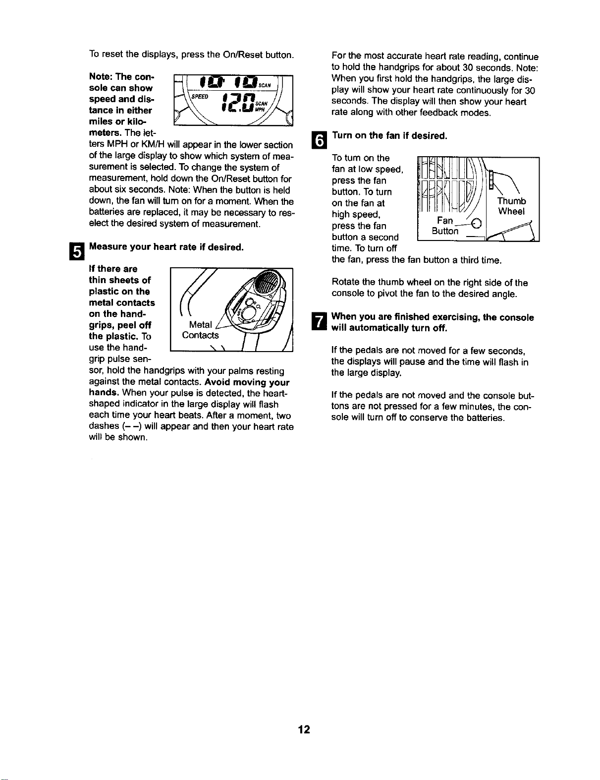
To reset the displays, press the On/Reset button.
Note: The con-
sole can show
speed and dis-
tance in either
miles or kilo-
meters. The let-
ters MPH or KM/H will appear in the lower section
of the large display to show which system of mea-
surement is selected. To change the system of
measurement, hold down the On/Reset button for
about six seconds. Note: When the button is held
down, the fan will turn on for a moment. When the
batteries are replaced, it may be necessary to res-
elect the desired system of measurement.
Measure your heart rate if desired.
If there are
thin sheets of
plastic on the
metal contacts
on the hand-
grips, peel off
the plastic, To
usethe hand-
grippulse sen-
sot, hold the handgrips with your palms resting
against the metal contacts. Avoid moving your
hands. When your pulse is detected, the heart-
shaped indicator in the large display will flash
each time your heart beats. After a moment, two
dashes (- -) will appear and then your heart rate
will be shown.
For the most accurate heart rate reading, continue
to hold the handgrips for about 30 seconds. Note:
When you first hold the handgrips, the large dis-
play will show your heart rate continuously for 30
seconds. The display will then show your heart
rate along with other feedback modes.
m
Turn on the fan if desired.
To tum on the
fan at low speed,
press the fan
button. To turn
on the fan at
high speed,
press the fan
button a second
time. Toturn off
the fan, press the fan button a third time.
Rotate the thumb wheel on the right side of the
console to pivot the fan to the desired angle.
B When you are finished exercising, the console
will automatically turn off.
If the pedals are not moved for a few seconds,
the displays will pause and the time willflash in
the large display.
If the pedals are not moved and the console but-
tons are not pressed for a few minutes, the con-
sole will turn off to conserve the batteries.
12
HOW TO USE A SMART PROGRAM
Each Smart program willautomatically change the
resistanceofthe pedals and prompt you toincrease or
decrease yourpace as itguides youthroughaneffec-
tiveworkout.Programs 3 and 4 are weightloss pro-
grams, program5 isan aerobic program,and program
6 isa high-performancainterval-trainingprogram.
Followthe steps below to use a Smart program.
B Turn on the console.
See step 1 on page 11.
B
Select one of the Smart programs.
Each time the console is
turned on, the manual
mode will be selected. To
select a Smart program,
press the Program button
repeatedly until the num-
ber 3, 4, 5, or 6 appears in
the small disptay.
B
Begin pedaling to start the program.
To startthe program, simply begin pedaling.Each
Smart program consistsof 20 or 30 one-minute
periods, One resistancelevel and one target pace
are programmedfor each period. (The same
resistancelevel and/ortarget pace may be pro-
grammedfor two or more consecutiveperiods.)
At the end of each period of the program, the
resistance of the pedals will automaticallychange
if a different resistance level is programmed for
the next period. Note: If the resistance level is too
high or too low, you can change it by pressing the
+ and - buttons below the large display. However,
when the current period is completed, the resis-
tance of the pedals will automatically change if a
different resistance level is programmed for the
next period.
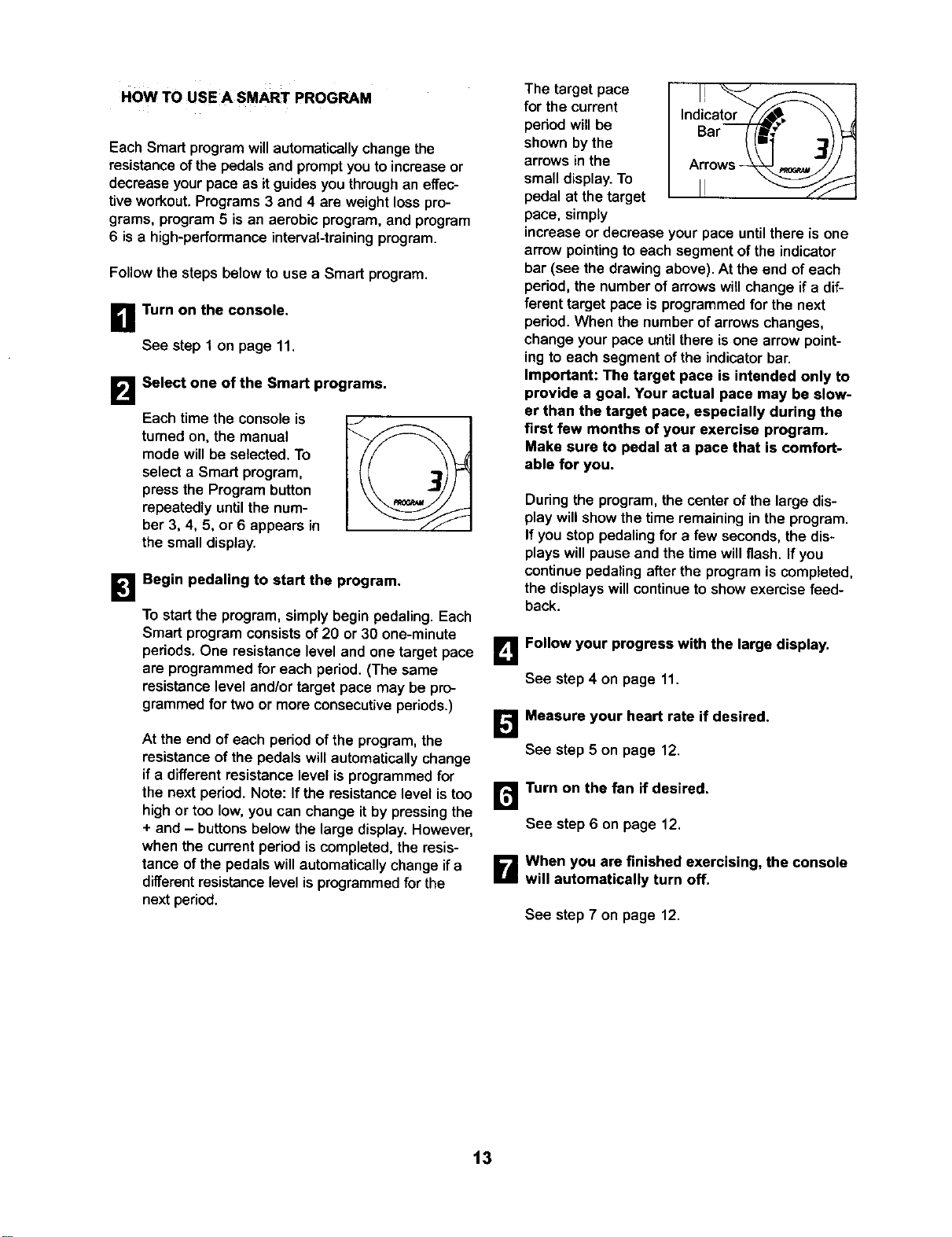
The target pace
for the current
period will be
shown by the
arrows in the
small display. To
pedal at the target
pace, simply
Indicator--s, \\ ,
Bar _f_' ..1_)_::_
Arrows--_ _ jJ
increase or decrease your pace until there is one
arrow pointing to each segment of the indicator
bar (see the drawing above). At the end of each
period, the number of arrows will change if a dif-
ferent target pace is programmed for the next
period.When the number of arrows changes,
change your pace until there is one arrow point-
ing to each segment of the indicator bar.
Important: The target pace is intended only to
provide a goal. Your actual pace may be slow-
er than the target pace, especially during the
first few months of your exercise program.
Make sure to pedal at a pace that is comfort-
able for you.
During the program, the center ofthe large dis-
play willshow the time remaining in the program.
If you stop pedalingfor a few seconds,the dis-
playswill pause and the time willflash. If you
continuepedaling afterthe programis completed,
the displayswillcontinueto show exercise feed-
back.
B Follow your progress with the large display.
See step4 on page 11.
Measure your heart rate if desired,
See step 5 on page 12.
r_ Turn on the fan if desired.
See step 6 on page 12.
B When you are finished exercising, the console
will automatically turn off.
See step 7 on page 12.
t3
HOW TO USE A HEART RATE PROGRAM
Heart Rate program 1 is designed to keep your heart
rate between 65% and 85% of your maximum heart
rate during your workout. (Your maximum heart rate is
estimated by subtracting your age from 220. For
example, if you are 25 years old, your maximum heart
rate is 195 beats per minute.) Heart Rate program 2 is
designed to keep your heart rate near a target heart
rate that you select.
Follow the steps below to use a Heart Rate program.
B Turn on the console,
See step 1 on page 11.
B
Select one of the Heart Rate programs.
Each time the console is
turned on, the manual
mode will be selected. To
select a Heart Rate pro-
gram, press the Program
button repeatedly until the
number 1 or 2 appears in
the small display.
/
B
Enter your age or a target heart rate.
If program 1 is selected, the wordAGE will
appear in the large display and the current age
settingwillflash, If you have already entered your
age, press the Enter button.Ifyou have not
entered yourage, press the small + and - buttons
to enter yourage. Then, press the Enter button.
Once you have enteredyour age, it willbe saved
in memory until the batteriesare replaced.
If program 2 is selected, the letters PLS (pulse)
will appear in the large display and the current
target heart rate will flash. If you do not wish to
change the target heart rate, press the Enter but-
ton. If you wish to change the target heart rate,
press the small + and - buttons. Then, press the
Enter button. The target heart rate can be from 70
to 170 beats per minute.
B
Hold the handgrip pulse sensor.
It is not necessary to hold the handgrips continu-
ously during a Heart Rate program; however, you
must hold the handgdps frequently for the program
to operate properly. Each time you hold the
handgrips, keep your hands on the metal con-
tacts for at least 30 seconds. Note: When you
are notholding the handgnps,the letters PLS will
appear in the large display instead of your heart
rate.
IL_ Begin pedaling to start the program.
To startthe program, simply begin pedaling.
Program 1 consistsof 20 one-minuteperiods.
One resistancelevel and one target heart rate are
programmedfor each period. (The same resis-
tance level and/ortarget heart rate may be pro-
grammed for two or more consecutiveperiods.)
Program 2 issixtyminuteslong (you may choose
to use only part ofthe program).The same resis-
tance leveland target heart rateare programmed
for the entire program.
If program 1 is selected, the resistanceof the
pedals willperiodically change. (Note: If the resis-
tance level is too highor too low,you can change
itby pressingthe + and - buttonsbelowthe large
display.However, when the current periodiscom-
pleted, the resistanceofthe pedals may automati-
callychange.) If program 2 is selected, the
resistanceofthe pedalswillnot change. Note:
You can changethe resistancelevel for the entire
programby pressingthe + and - buttonsbelow
the large displayif desired.
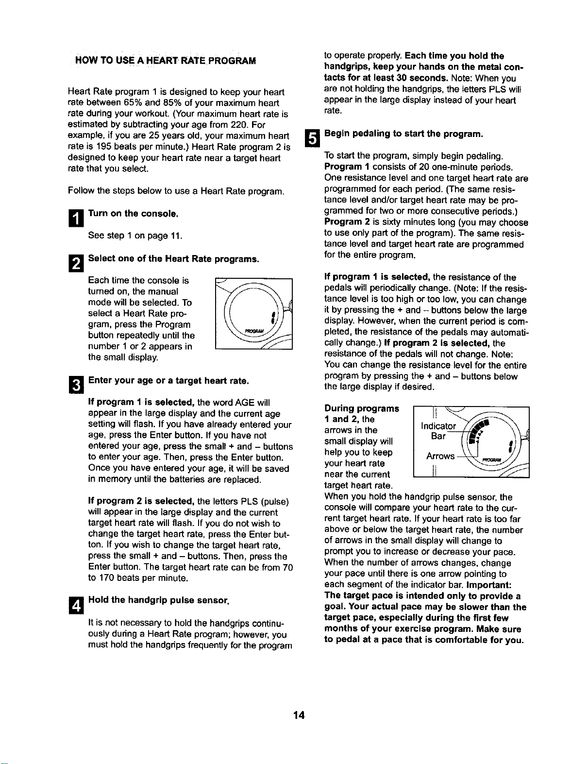
During programs
1 and 2, the
arrows in the
smalldisplay will
helpyou to keep
your heart rate
near the current
target heart rate.
Indicat_,._" \\
Bar //f_ _)
Arrows -_ p._._/i"
When you hold the handgrip pulse sensor, the
console will compare your heart rate to the cur-
rent target heart rate. If your heart rate is too far
above or below the target heart rate, the number
of arrows in the small display will change to
prompt you to increase or decrease your pace.
When the number of arrows changes, change
your pace until there is one arrow pointing to
each segment of the indicator bar. Important:
The target pace is intended only to provide a
goal. Your actual pace may be slower than the
target pace, especially during the first few
months of your exercise program. Make sure
to pedal at a pace that is comfortable for you.
14
Note: If you stop pedaling for a few seconds, the
program will end. To use the program again, rese-
lect it and start it at the beginning.
r_ Follow your progress with the large display.
See step 4 on page 11.
B Turn on the fan if desired.
See step 6 on page 12.
B When you are finished exercising, the console
will automatically turn off.
See step 7 on page 12.
HOW TO CONNECT YOUR CD PLAYER, VCR,
OR COMPUTER
To use iFIT.com CDs, the ellipticalcmsstrainer must be
connectedto yourportableCD player,portablestereo,
home stereo,or computerwithCD player.See pages 15
to 17 forconnecting instructions.To use iFIT.com
videocassettes, the ellipticalcresstrainermustbe con-
nectedtoyourVCR. See page 17 for connectinginstruc-
tions.To use iFIT.com programs directly from our
Web site, the ellipticalcresstrainermustbeconnected to
yourcomputer.See page 17 for connectinginstructions.
HOW TO CONNECT YOUR PORTABLE CD PLAYER
Note: If your CD player has separate LINE OUT and
PHONES jacks, see instruction A below. If your CD
player has only one jack, see instruction B.
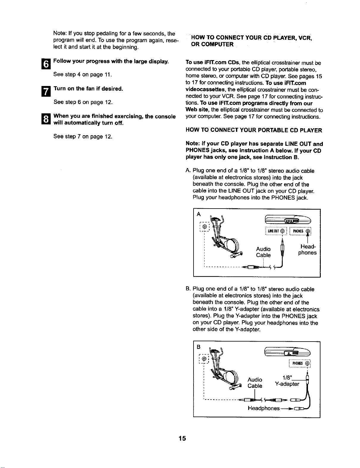
A. Plugone end of a 1/8" to 1/8"stereo audio cable
(available at electronicsstores) intothe jack
beneath the console.Plug the otherend ofthe
cable intothe LINE OUT jack on yourCD player.
Plugyour headphones intothe PHONES jack.
Audio _ Head-
Cable phones
..............
B. Plug one end of a 1/8" to 1/8"stereo audio cable
(available at electronicsstores) intothe jack
beneath the console.Plug theother end of the
cable intoa !/8" Y-adapter (available at electronics
stores).Plug the Y-adapterintothe PHONES jack
on yourCD player. Plugyour headphonesintothe
otherside of the Y-adapter.
.. ........... I..
i
Audio 1/8"_
, Cable Y-adapter
Headphones
15
HOW TO CONNECT YOUR PORTABLE STEREO
Note: If your stereo has an RCA-type AUDIO OUT
jack, see instruction A below. If your stereo has a
1/8" LINE OUT jack, see instruction B. If your
stereo has only a PHONES jack, see instruction C.
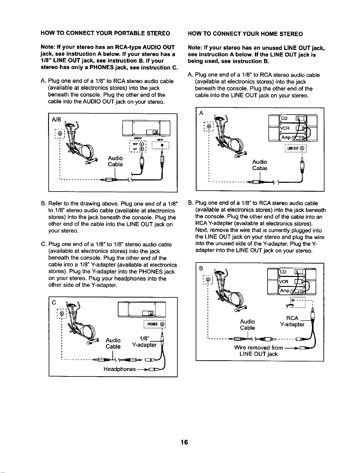
A. Plug one end of a 1/8"to RCA stereo audio cable
(available at electronics stores) into thejack
beneath the console. Plug the other end of the
cable into the AUDIO OUT jack on your stereo•
Audio
Cable <_ W
.............. ]
HOW TO CONNECT YOUR HOME STEREO
Note: If your stereo has an unused LINE OUT jack,
see instruction A below, If the LINE OUT jack is
being used, see instruction B.
A. Plug one end of a 1/8" to RCA stereo audio cable
(available at electronics stores) into the jack
beneath the console. Plug the other end of the
cable into the LINE OUT jack on your stereo.
Audio
Cable
B. Refer to the drawing above. Plug one end of a 1/8"
to 1/8"stereo audio cable (available at electronics
stores) into the jack beneath the console. Plug the
other end of the cable into the LINE OUT jack on
your stereo.
C. Plug one end of a 1/8" to 1/8" stereo audio cable
(available at electronics stores) into the jack
beneath the console• Plug the other end of the
cable into a 1/8" Y-adapter (available at electronics
stores). Plug the Y-adapter into the PHONES jack
on your stereo. Plug your headphones into the
other side of the Y-adapter.
Audio 1/8"
Cable Y-adapter
B. Plug one end of a 1/8"to RCA stereo audio cable
(available at electronicsstores) into thejack beneath
the console. Plug the other end of the cable into an
RCA Y-adapter (available at electronics stores).
Next, remove the wire that is currently plugged into
the LINE OUT jack on your stereo and plug the wire
into the unused side of the Y-adapter. Plug the Y-
adapter into the LINE OUT jack on your stereo.
RCA __
Audio Y-adapter
Cable
Wire removed from -I>-[:3=-'
LINE OUT jack
16
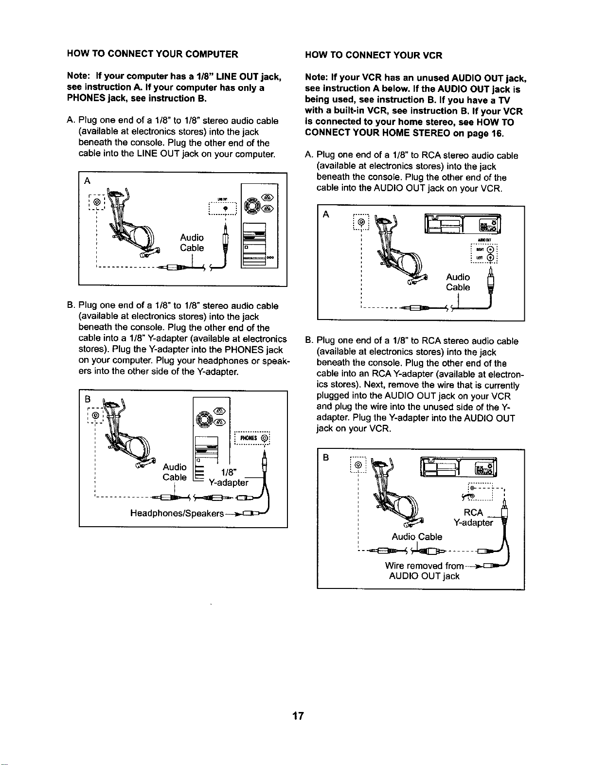
HOW TO CONNECT YOUR COMPUTER
Note: If your computer has a 1/8" LINE OUT jack,
see instruction A. If your computer has only a
PHONES jack, see instruction B.
A. Plug one end of a 1/8" to 1/8"stereo audio cable
(available at electronics stores) into the jack
beneath the console. Plug the other end of the
cable into the LINE OUT jack on your computer.
A
q
_^ _
B. Plug one end of a 1/8" to 1/8" stereoaudio cable
(available at electronics stores) into the jack
beneaththe console.Plug the otherend ofthe
cable intoa 1/8"Y-adapter (available at electronics
stores).Plug the Y-adapter intothe PHONES jack
on yourcomputer.Plug yourheadphones or speak-
ers intothe otherside ofthe Y-adapter.
Audio
Headphones/Speakers-_..c]E>_
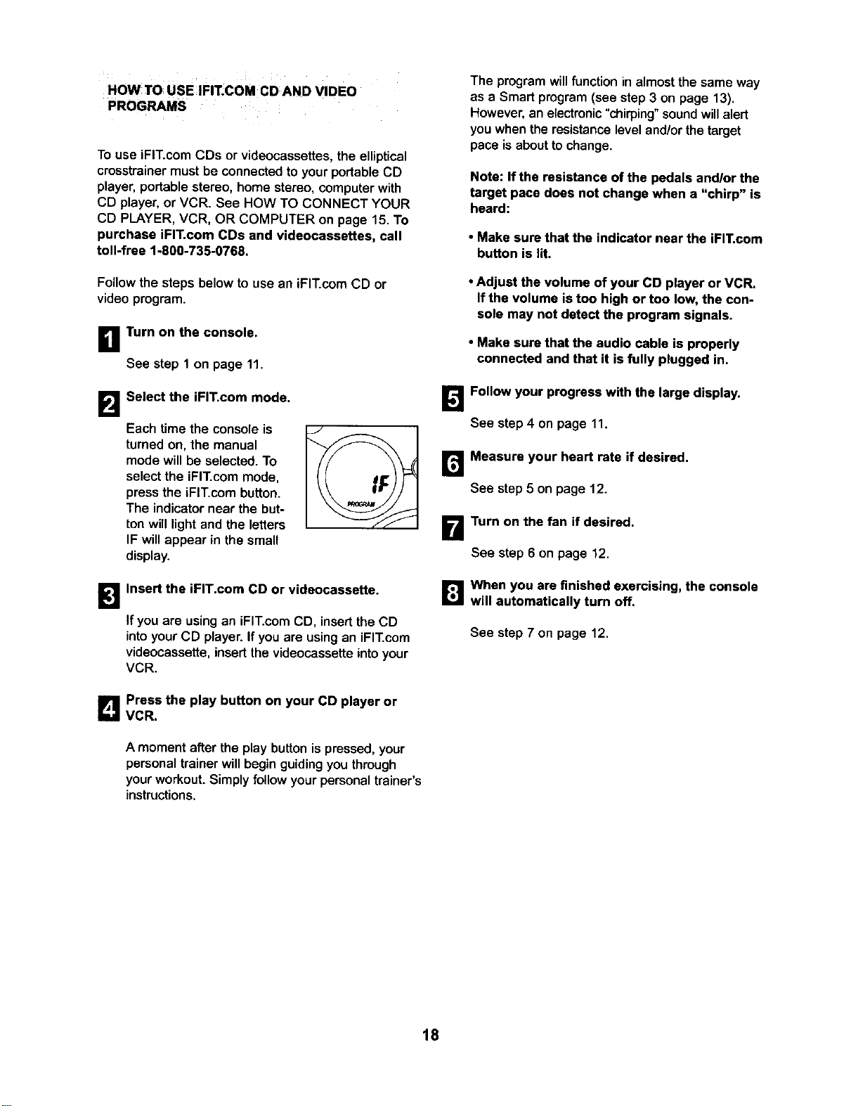
HOW TO CONNECT YOUR VCR
Note: If your VCR has an unused AUDIO OUT jack,
see instruction A below. If the AUDIO OUT jack is
being used, see instruction BoIf you have a TV
with a built-in VCR, see instruction B. If your VCR
is connected to your home stereo, see HOW TO
CONNECT YOUR HOME STEREO on page 16.
A. Plug one end ofa 1/8" to RCA stereo audio cable
(available at electronics stores) into the jack
beneath the console.Plugthe other end ofthe
cable intothe AUDIO OUT jack on yourVCR.
A
B. Plug one end of a 1/8" to RCA stereo audio cable
(available at electronics stores) into thejack
beneath the console. Plug the other end of the
cable into an RCA Y-adapter (available at electron-
ics stores). Next, remove the wire that is currently
plugged into the AUDIO OUT jack on your VCR
and plug the wire into the unused side of the Y-
adapter. Plug the Y-adapter into the AUDIO OUT
jack on your VCR.
B
i" "._L"="
Audio Cable
Wire removed from-_,,-[_ _
AUDIO OUT jack
17
HOWTO USE FIT.COM CDAND VIDEO
PROGRAMS
To use iFIT.com CDs or videocassettes,the elliptical
crosstrainer must be connected to your portable CD
player, portable stereo, home stereo, computer with
CD player, or VCR. See HOW TO CONNECT YOUR
CD PLAYER, VCR, OR COMPUTER on page 15. To
purchase iFIT.com CDs and videocassettes, call
toll-free %800-735-0768.
The program willfunction in almost the same way
as a Smart program (see step 3 on page 13).
However, an electronic "chirping" sound will alert
you when the resistance level and/or the target
pace is about to change.
Note: If the resistance of the pedals and/or the
target pace does not change when a "chirp" is
heard:
• Make sure that the indicator near the iFIT, com
button is lit.
Follow the steps below to use an iFIT.com CD or
video program.
n Turn on the console,
See step 1 on page 11,
• Adjust the volume of your CD player or VCR.
If the volume is too high or too low, the con-
sole may not detect the program signals.
• Make sure that the audio cable is properly
connected and that it is fully plugged in.
B
Select the iFIT.com mode.
Each time the console is
turned on, the manual
mode willbe selected.To
select the iFIT.com mode,
pressthe iFIT.com button.
The indicatornear the but-
ton will lightand the letters
IF will appear in the small
display.
Follow your progress with the large display.
See step 4 on page 11.
Measure your heart rate if desired.
See step 5 on page 12.
Turn on the fan if desired.
See step 6 on page 12.
B
Insert the iFIT.com CD or videocassette.
Ifyou are using an iFIT.com CD, insert the CD
intoyourCD player. Ifyou are using an iFIT.com
videocassette, insert the videocassette into your
VCR.
[]When you are finished exercising, the console
will automatically turn off.
See step 7 on page 12.
Press the play button on your CD player or
VCR.
A moment after the play button is pressed, your
personal trainer will begin guiding you through
your workout. Simply follow your personal trainer's
instructions.
18
HOW 1"0 USE PROGRAMS DIRECTLY FROM B Start your Web browser, if necessary, and go
OUR WEB SITE to our Web site at www.iFIT.com.
Our Web site at www.iFIT.com allows you to play
iFIT.com programs directly from the intemet. To use
programs from our Web site, the elliptical crosstrainer
must be connected to your computer. See HOW TO
CONNECT YOUR COMPUTER on page 17. In addi-
tion, you must have an internet connection and an
internet service provider. A list of specific system
requirements will be found on our Web site.
Follow the steps below to use a program from our
Web site.
B Turn on the console.
See step 1 on page 11.
B
1_'_ Follow the desired links on our Web site to
select a program.
r_ Follow the on-line instructions to start the
program.
When you start the program, an on-screen count-
down will begin.
B Return to the elliptical crosstrainer and begin
pedaling.
Select the iFIT.com mode.
When the on-screen countdown ends, the pro-
gram will begin. The program will function in
almost the same way as a Smart program (see
step 3 on page 13). However, an electronic "chirp-
ing" sound will alert you when the resistance level
and/or the target pace is about to change.
Each time the console is
turned on, the manual
mode will be selected. To
select the iFIT.com mode,
press the iFIT.com button.
The indicator near the but-
ton will light and the letters
IF will appear in the small
display.
B
B Go to your computer and start an internet con-
nection.
Follow your progress with the large display.
See step 4 on page 11.
Measure your heart rate if desired,
See step 5 on page 12,
_lWhen you are finished exercising, the console
will automatically turn off.
See step 7 on page 12.
19
MAINTENANCE AND TROUBLESHOOTING
Inspect andtighten all parts of the elliptical crosstrainer
regularly. Replace any worn parts immediately.
To clean the ellipticalcrosstrainer,use a damp cloth
and a small amount of mild soap. Important; To
avoid damage to the console, keep liquids away
from the console and keep the console out of
direct sunlight,
BATTERY REPLACEMENT
If the console displays become dim, the batteries
should be replaced; most console problems are the
result of low batteries. Refer to assembly step 5 on
page 7 for replacement instructions.
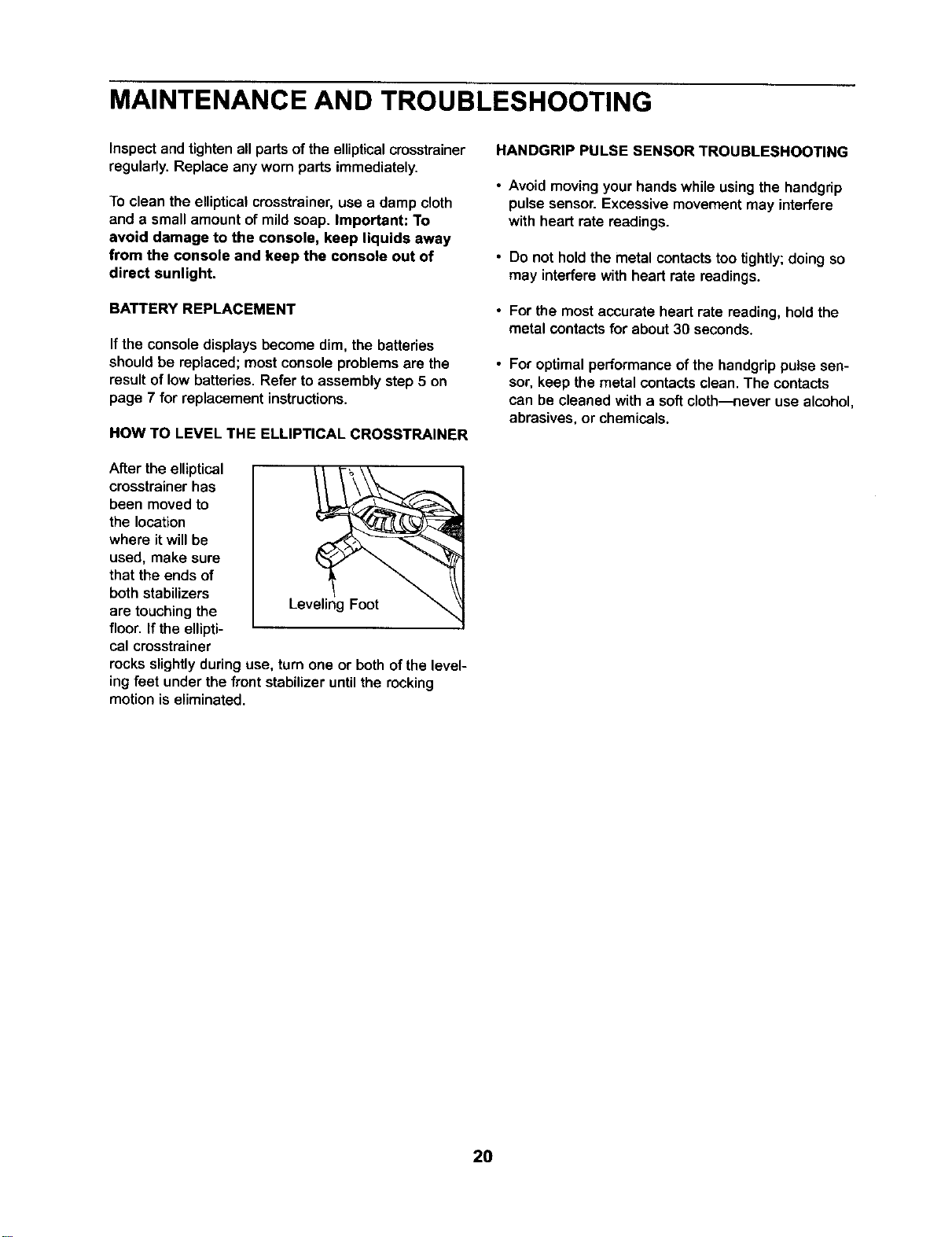
HOW TO LEVEL THE ELLIPTICAL CROSSTRAINER
After the elliptical
crosstrainer has
been moved to
the location
where it will be
used, make sure
that the ends of
both stabilizers
are touching the
floor. If the ellipti-
cal crosstrainer
rocks slightly during use, turn one or both of the level-
ing feet under the front stabilizer until the rocking
motion is eliminated.
HANDGRIP PULSE SENSOR TROUBLESHOOTING
• Avoid moving your hands while using the handgrip
pulse sensor. Excessive movement may interfere
with heart rate readings.
• Do not hold the metal contactstoo tightly;doing so
may interfere with heart rate readings.
• For the mostaccurate heart rate reading, hold the
metal contacts for about 30 seconds.
For optimal performance of the hendgrip pulse sen-
sor, keep the metal contacts clean. The contacts
can be cleaned with a soft cloth---never use alcohol,
abrasives, or chemicals.
20
CONDITIONING GUIDELINES
WARNING:
• Before beginning this or any exercise pro-
gram, consult your physician. This is espe-
cially important for persons over the age of
35 or persons with pre-existing health prob-
lems.
• The pulse sensor is not a medical device.
Various factors may affect the accuracy of
heart rate readings. The pulse sensor is
intended only as an exercise aid In deter-
mining heart rate trends in general.
The following guidelines will helpyou to plan your
exercise program. Remember that proper nutrition
and adequate rest are essential for successful results.
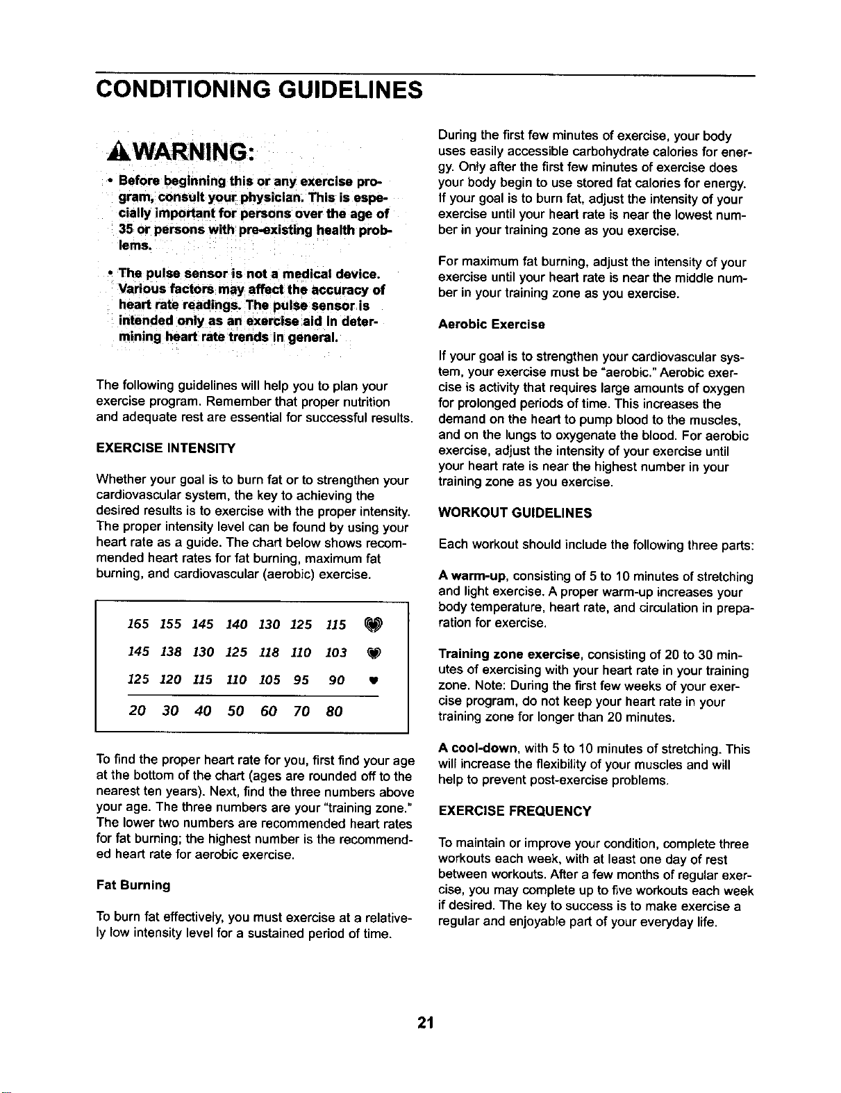
EXERCISE INTENSITY
Whether your goal isto burn fat or to strengthen your
cardiovascularsystem,the key to achieving the
desired results is to exercise with the proper intensity.
The proper intensity level can be found by using your
heart rate as a guide. The chart below shows recom-
mended heart rates for fat burning, maximum fat
burning, and cardiovascular (aerobic) exercise.
165 155 145 140 130 125 115
145 138 130 125 118 110 103 _f_
125 120 115 110 105 95 90
20 30 40 50 60 70 80
To find the proper heart rate for you, first find yourage
at the bottom ofthe chart (ages are roundedoffto the
nearest ten years). Next, findthe three numbersabove
yourage. The three numbers are your"training zone."
The lower two numbersare recommended heart rates
for fat burning;the highestnumber isthe recommend-
ed heart rate for aerobic exercise.
Fat Burning
To burn fat effectively, you mustexercise at a relative-
ly low intensity level for a sustained period of time.
Duringthe firstfew minutesof exercise,your body
uses easily accessiblecarbohydratecalories for ener-
gy. Only after the first few minutes of exercise does
your body begin to use stored fat calories for energy.
If your goal is to burn fat, adjust the intensity of your
exercise until your heart rate is near the lowest num-
ber in your training zone as you exercise.
For maximum fat burning, adjustthe intensity of your
exercise until your heart rate is near the middle num-
ber in your training zone as you exercise.
Aerobic Exercise
If your goal is to strengthenyour cardiovascular sys-
tem, yourexercise mustbe =aerobic."Aerobic exer-
cise is activity that requires large amounts of oxygen
for prolonged periods of time. This increases the
demand on the heart to pump blood to the muscles,
and on the lungs to oxygenate the blood. For aerobic
exercise, adjust the intensity of your exercise until
your heart rate is near the highest number in your
training zone as you exercise.
WORKOUT GUIDELINES
Each workout should include the following three parts:
A warm-up, consisting of 5 to 10 minutesof stretching
and lightexercise.A properwarm-up increases your
body temperature, heart rate, and circulationin prepa-
ration for exercise.
Training zone exercise, consistingof 20 to 30 min-
utes of exercisingwith yourheart rate in yourtraining
zone. Note: Duringthe firstfew weeks ofyourexer-
cise program,do not keep your heart rate in your
trainingzone for longerthan 20 minutes.
A cool-down, with 5 to 10 minutes of stretching.This
willincrease theflexibilityof yourmuscles and will
helpto preventpost-exerciseproblems.
EXERCISE FREQUENCY
To maintain or improve your condition, complete three
workouts each week, with at least one day of rest
between workouts. After a few months of regular exer-
cise, you may complete up to five workouts each week
if desired. The key to success is to make exercise a
regular and enjoyable part of your everyday life.
21
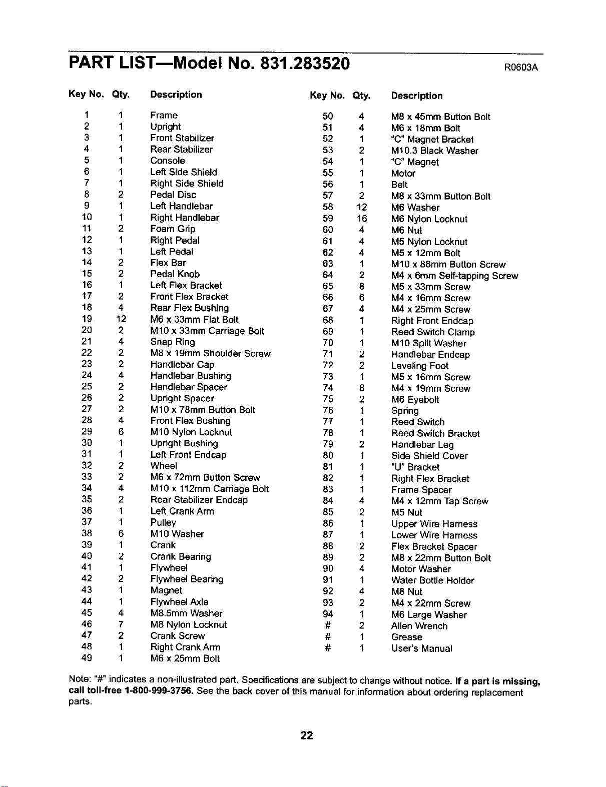
PART LISTmModel No. 831.283520 R0603A
Key No. Qty. Description Key No. Qty. Description
1 1 Frame 50 4 M8 x 45mm ButtonBolt
2 1 Upright 51 4 M6 x 18mm Bolt
3 1 Front Stabilizer 52 1 "C" Magnet Bracket
4 1 Rear Stabilizer 53 2 M10.3 Black Washer
5 1 Console 54 1 "C" Magnet
6 1 Left Side Shield 55 1 Motor
7 1 Right Side Shield 56 1 Belt
8 2 Pedal Disc 57 2 M8 x 33mm Button Bolt
9 1 Left Handlebar 58 12 M6 Washer
10 1 Right Handlebar 59 16 M6 Nylon Locknut
11 2 Foam Grip 60 4 M6 Nut
12 1 Right Pedal 61 4 M5 Nylon Locknut
13 1 Left Pedal 62 4 M5 x 12mm Bolt
14 2 Flex Bar 63 1 M10 x 88mm Button Screw
15 2 Pedal Knob 64 2 M4 x 6mm Self-tapping Screw
16 1 Left Flex Bracket 65 8 M5 x 33mm Screw
17 2 Front Flex Bracket 66 6 M4 x 16mm Screw
18 4 Rear Flex Bushing 67 4 M4 x 25mm Screw
19 12 M6 x 33mm Flat Bolt 68 1 Right Front Endcap
20 2 M10 x 33mm Carriage Bolt 69 1 Reed Switch Clamp
21 4 Snap Ring 70 1 M10 SplitWasher
22 2 M8 x 19mm Shoulder Screw 71 2 Handlebar Endcap
23 2 Handlebar Cap 72 2 LevelingFoot
24 4 Handlebar Bushing 73 1 M5 x 16mm Screw
25 2 Handlebar Spacer 74 8 M4 x 19mm Screw
26 2 Upright Spacer 75 2 M6 Eyebolt
27 2 M10 x 78mm Button Bolt 76 1 Spring
28 4 Front Flex Bushing 77 1 Reed Switch
29 6 M1O Nylon Locknut 78 1 Reed Switch Bracket
30 1 Upright Bushing 79 2 Handlebar Leg
31 1 Left Front Endcap 80 1 Side Shield Cover
32 2 Wheel 81 1 "U" Bracket
33 2 M6 x 72mm Button Screw 82 1 Right Flex Bracket
34 4 M10 x 112mm Carriage Bolt 83 1 Frame Spacer
35 2 Rear Stabilizer Endcap 84 4 M4 x 12mm Tap Screw
36 1 Left Crank Arm 85 2 M5 Nut
37 1 Pulley 86 1 Upper Wire Harness
38 6 MIO Washer 87 1 Lower Wire Harness
39 1 Crank 88 2 Flex Bracket Spacer
40 2 Crank Bearing 89 2 M8 x 22mm Button Bolt
41 1 Flywheel 90 4 Motor Washer
42 2 Flywheel Bearing 91 1 Water Bottle Holder
43 1 Magnet 92 4 M8 Nut
44 1 Flywheel Axle 93 2 M4 x 22mm Screw
45 4 M8.5mm Washer 94 1 M6 Large Washer
46 7 M8 Nylon Locknut # 2 Allen Wrench
47 2 Crank Screw # 1 Grease
48 1 Right Crank Arm # 1 User's Manual
49 1 M6 x 25mm Bolt
Note: "#" indicatesa non-illustratedpart. Specifications are subject to changewithoutnotice. If a part is missing,
call toll-free 1-800-999-3756. See the back cover ofthis manual for informationabout orderingreplacement
parts.
22
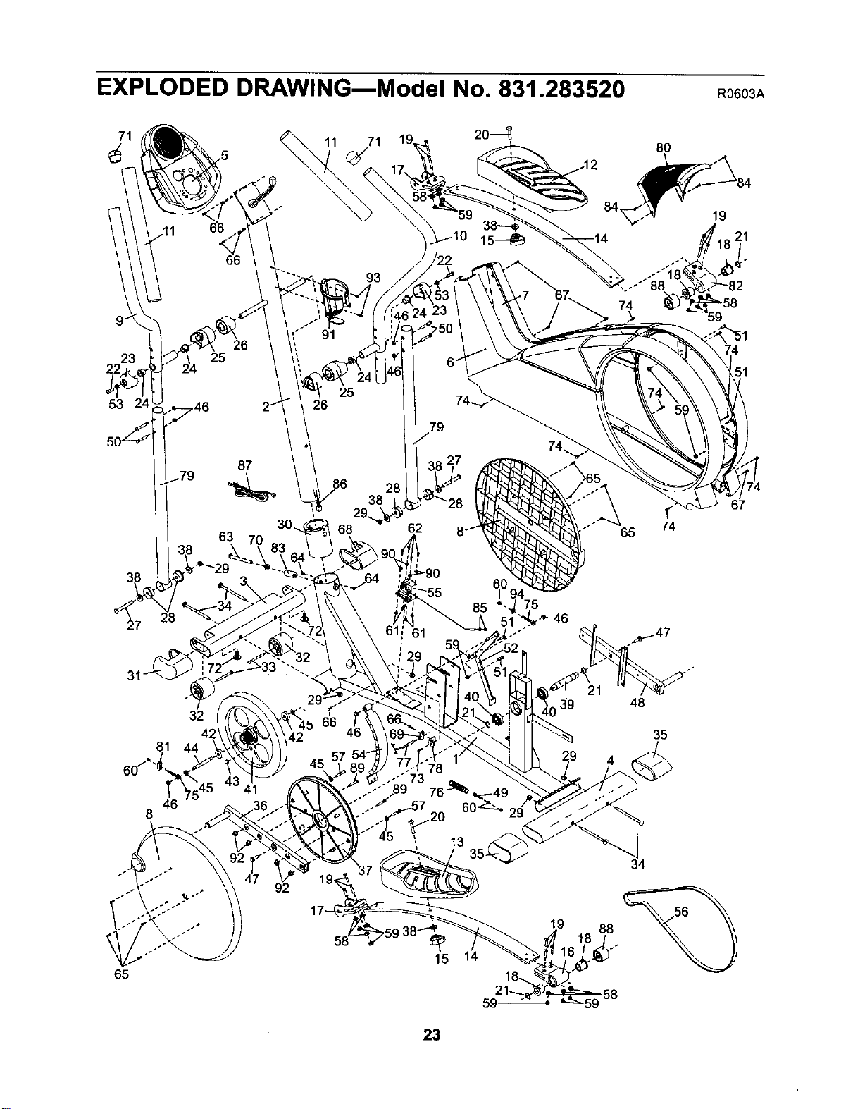
EXPLODED DRAWINGmModel No. 831.283520 R0603A
8O
9 _
23
25
53
87
63
38
68 62
,65
65
67
27
81
32
48
35
46
8
92
34
65
15 14
59-
88
23

_i! !i_ _ _i_ i_i
i!:ii_iii__ Your Home
For repair - in your home - of all major brand appliances, lawn and garden equipment,
or heating and cooling systems, no matter who made it, no matter who sold it!
For the replacement parts, accessories, and user's manuals that you need to do-it-yourself.
For Sears professional installation of home appliances
and items like garage door openers and water heaters.
1-800-4-MY-HOME _ Anytime,dayor night
(1-800-469-4663) (U.S.A.andCanadaj
www.sears.com www.sears.ca
iii!!ii
iliili_
ill!ill_
Our Home
For repair of carry-in products like vacuums, lawn equipment,
and electronics, call or go on-line for the location of your nearest
Sears Parts and Repair Center.
1-800-488-1222 Anytime, day or night (U.S.A. only)
www.sears.com
!!?ii
To purcnasea protection agreement (U.S.A.)
or maintenance agreement [Canada) on a product serviced by Sears:
1-800-827-6655 [u.sA.)
1-800-361-6665 (Canada)
iiiil
ili!iiii_i
_ii_iii _! iii!!i!!i
Para pedir servicio de reDaraci6n a domicilio y para ordenar piezas:
1-888-SU-HOGAR s" (1-888-784-6427)
SEARS
® Registered Trademark / TMTrademark / SMService Mark of Seers, Roebuck and Co
® Mama Registrada / TMMarca de F_brica / SMMarca de Servicio de Sears, Roebuck and Co,
f
FULL 90 DAY WARRANTY
f-
; For 90 days from the date of purchase, if failure occurs due to defect in material or workmanshipin this
Sears Elliptical Exerciser, contact the nearest Sears Service Center throughout the United States and
Sears will repair or replace the Elliptical Exerciser, free of charge.
This warranty does not apply when the Elliptical Exerciser is used commercially or for rental purposes.
This warranty gives you specific legal rights, and you may also have other rights which vary from state
to state.
Sears, Roebuck and Co., Dept. 817WA, Hoffman Estates, IL 60179
Part No. 197640 R0603A Printed in China © 2003 Sears, Roebuck and Co.

