Loading ...
Loading ...
Loading ...
6
About Your Snap Circuits
®
Parts
MOTOR MODULES
Disco Motor (DM)
The programmable fan (M8) is a motor with
an LED circuit. A motor converts electricity into
mechanical motion, in the form of a spinning
shaft. In the light motor electricity is transported
through the motor shaft to power an LED circuit,
with LEDs mounted on the fan blade. The motor
spins in both directions, but the light circuit only
works in one direction.
How does electricity turn the shaft in the motor?
Electricity is closely related to magnetism,
and an electric current owing in a wire has a
magnetic eld similar to that of a very, very tiny
magnet. Inside the motor are three coils of wire
with many loops. If a large electric current ows
through the loops, the magnetic effects become
concentrated enough to move the coils. The
motor has a magnet inside, so as the electricity
moves the coils to align them with the permanent
magnet, the shaft spins.
The LEDs in the fan blade are flashed in a
pattern based on the programmed phrase, and
synchronized with the motor speed. The ashes
are precisely timed and are very brief, but your eyes
can’t react fast enough and the ashed pattern
gives the illusion of words oating in space. You
can change the messages displayed;
see project 15. UP, MODE, and
DOWN are controlled by
connecting those snaps to
(-) using switches or
the selector (S8).
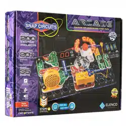
The disco motor (DM) is a motor with a gearbox
attached to the shaft, and an LED module
mounted on it. The gearbox makes its shaft spin
slower but with more force than the shaft that is
directly attached to the motor, so it can spin the
disco covers. The LED module has red, green,
and blue LEDs, connected in parallel.
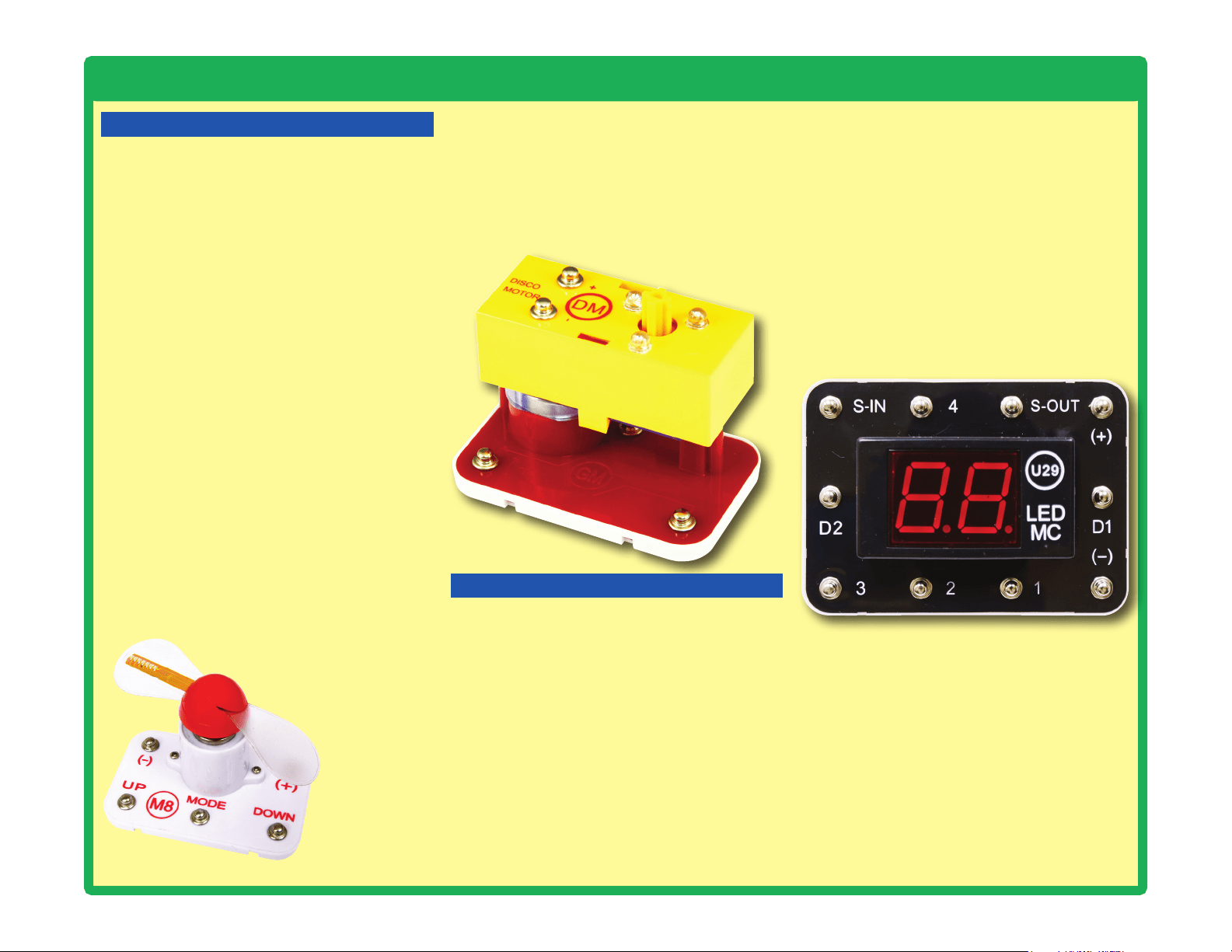
LED MC (U29):
(+) - Power from batteries
(—) - Power return to batteries
S-IN - Takes input from the selector (S8)
S-OUT - An output, often connected to an LED
1 - An output, often connected to an LED
2 - An output, usually connected to the speaker
3 - Takes input from the selector (S8)
4 - An output, often connected to an LED
D1 - Used to shut off the right LED display
D2 - Used to shut off the left LED display
LED MC (U29)
The Snap Circuits
®
Arcade page on our website
(https://shop.elenco.com/consumers/snap-
circuits-arcade.html) has additional information
about the LED MC, including a schematic
diagram, the program it is running, links to
software that will allow you to modify the program
or write your own programs for it, and how to
purchase a programming cable for it (which is
only needed if you want to reprogram it). The
microcontroller used is the PICAXE
®
08M2, which
has a special programming interface that makes
it easy to use. You can also nd information
about the PICAXE
®
08M2 from its manufacturer
at www.picaxe.co.uk.
LED DISPLAY & MICROCONTROLLER
The LED MC module (U29) has a dual 7-segment
LED display, a microcontroller, and supporting
parts. The microcontroller is a mini computer
which can be programmed to perform different
tasks, including monitoring things and making
things happen. It is pre-programmed for use with
the games projects. See project 17 for how to
select games on it.
LED MC outputs cannot control the motors in
the disco motor (DM) or programmable fan (M8)
directly, so an interface transistor must be used.
LED MC outputs can control your speaker (SP2)
and LEDs (D1, D2, D10, and the LEDs in the
disco motor) directly.
Programmable Fan (M8)
Loading ...
Loading ...
Loading ...