Loading ...
Loading ...
Loading ...
5
About Your Snap Circuits
®
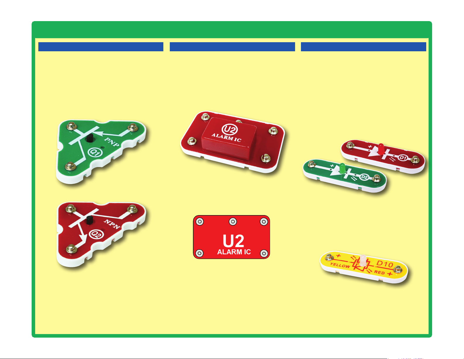
Parts
IN1
(–)
IN2
IN3
OUT
Connections:
IN1, IN2, IN3 - control inputs
(–) - power return to batteries
OUT - output connection
Connect control inputs to (+) power to make ve
alarm sounds, see project 59 for an example of
proper connections.
TRANSISTORS
The PNP & NPN transistors (Q1 & Q2) are
components that use a small electric current
to control a large current, and are used in
switching, amplier, and buffering applications.
They are easy to miniaturize, and are the main
building blocks of integrated circuits including
the microprocessor and memory circuits in
computers.
PNP & NPN Transistors (Q1 & Q2)
ALARM IC
The alarm IC (U2) contains a specialized sound-
generation integrated circuit (IC) and other
supporting components (resistors, capacitors,
and transistors) that are always needed with it.
A schematic for it is available at https://www.
elenco.com/faqs/.
Red & Green LEDs (D1 & D2)
Red/Yellow LED (D10)
The red/yellow LED (D10) is like the others but
has red and yellow LEDs connected in opposite
directions.
LEDs
The red & green LEDs (D1 & D2) are light
emitting diodes, and may be thought of as a
special one-way light bulb. In the “forward”
direction, (indicated by the “arrow” in the
symbol) electricity ows if the voltage exceeds a
turn-on threshold (about 1.5V for red and yellow,
about 2.0V for green, and about 3.0V for blue;
brightness then increases. A high current will
burn out an LED, so your Snap Circuits
®
LEDs
have internal resistors to protect them. LEDs
block electricity in the “reverse” direction.
Alarm IC (U2)
Loading ...
Loading ...
Loading ...