Loading ...
Loading ...
Loading ...
12
WIRING
WARNING: To reduce the risk of re, electrical shock or personal injury, wire connectors provided
with this fan are designed to accept only one 12-gauge house wire and two lead wires from the fan. If
your house wire is larger than 12-gauge and there is more than one house wire to connect to the two
fan lead wires, consult an electrician for the proper size wire connectors to use. CAUTION: Be sure
the outlet box is properly grounded or that a ground (green or bare) wire is present.
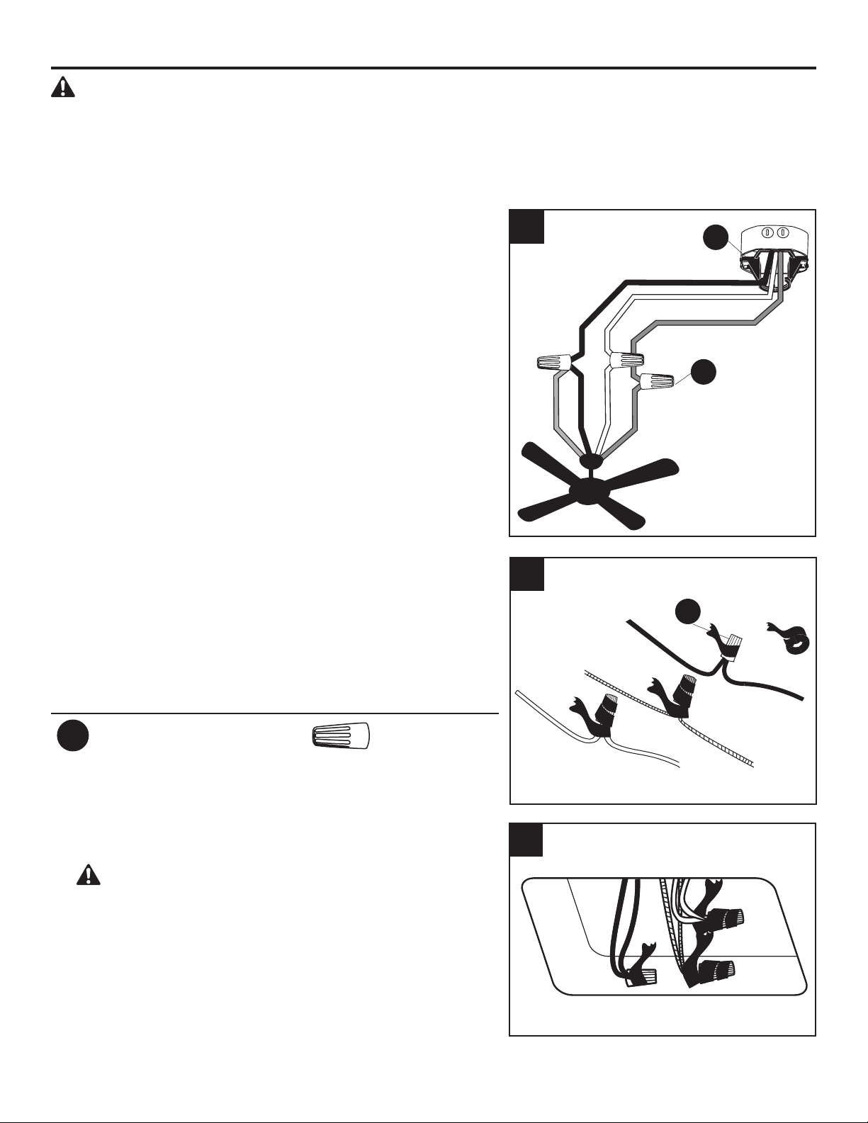
1. Connect supply and fan wires according to the diagram
and these steps:
• Connect the Green wires from the downrod (A)
and the mounting bracket (D) to the Bare/Green
(ground) supply wire. Note: Closemount installation
does not use downrod (A), so there will only be two
Green wires to connect.
• Connect the White wire from the fan to the White
(neutral) supply wire.
• Connect the Black and Blue wires from the fan to the
Black (hot) supply wire.
Secure all wiring connections together with wire
connectors (AA).
Note: If a second hot power wire is available from outlet
box, connect it to the blue (light power) wire from the
fan for separate light and fan control.
Note: The Blue wire is power for light. The Black wire
is power for the fan. The White wire is neutral/common.
The Green wire is the ground wire. If household supply
wires are dierent colors than referred to above, it is
recommended a professional electrician determines the
proper wiring.
Hardware Used
AA
Wire Connector x 3
2. Wrap electrical tape (not included) around each
individual wire connector (AA) down to the wire.
3. Turn the spliced/taped wires upward and gently push
the wires and wire connectors into the outlet box.
WARNING: Ensure no bare wire strands are visible
after making connections. Place Green and White wire
connections on opposite sides of outlet box from the
Black and Blue wire connections.
1
D
AA
AA
3
2
Black (Hot)
White (Neutral)
Bare/Green (Ground)
Black
Blue
White
Green
Loading ...
Loading ...
Loading ...