Loading ...
Loading ...
Loading ...
7
NOTE: Only non-combustible materials can be used in close proximity to this appliance.
NOTE:
All Models are delivered completely assembled. No further assembly is required. Refer to
the information below for assembly instructions.
This appliance is fitted with adjustable feet to enable the appliance to be positioned
securely and level. This should be carried out on completion of the gas connection. Refer
to the 'Gas Connection' section.
1. Check that all the feet are securely fitted.
2. Adjust the four feet to make the Range steady and level.
Optional Accessories (Refer to Replacement Parts List)
Plinth Kit. For installation details, refer to the instructions supplied with each kit.
NOTE: ALL GAS FITTING MUST ONLY BE CARRIED OUT BY AN QUALIFIED PERSON.
1. It is essential that the gas supply is correct for the appliance being installed and that adequate
supply pressure and volume are available. Carry out the following checks before installation:-
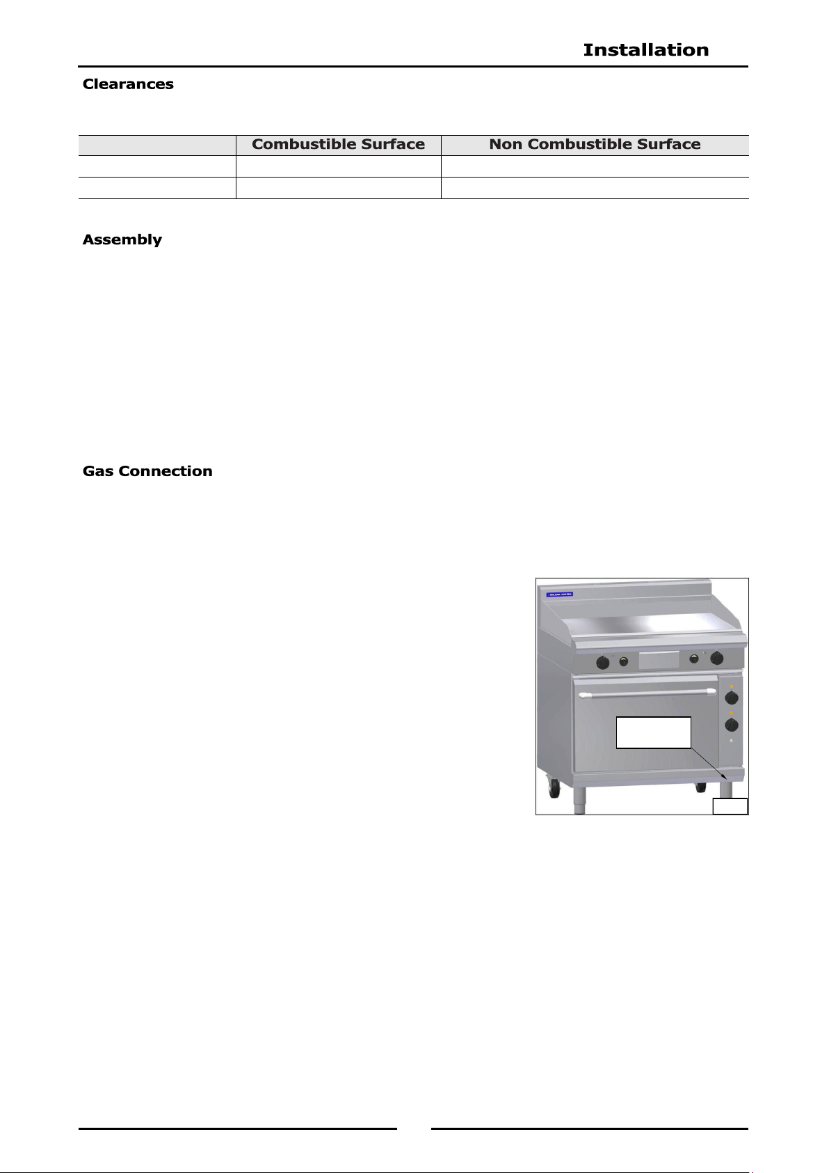
a. Gas Type the appliance has been supplied for is shown on
coloured stickers located above the gas connection point and
next to the rating plate. Check that this is correct for the gas
supply the appliance is being installed for. The gas
conversion procedure is detailed in this manual.
b. Supply Pressure required for this appliance is shown in the
'Specifications' section of this manual. Check the gas supply
to ensure adequate supply pressure exists.
c. Input Rate of this appliance is shown on the Rating Plate
and in the ‘Specifications’ section of this manual. The input
rate should be checked against the available gas supply line
capacity. Particular note should be taken if the appliance is
being added to an existing installation.
NOTE: It is important that adequately sized piping runs directly to
the connection joint on the
appliance with as few tees and elbows as possible to give
maximum supply volume.
2. Fit the gas regulator supplied, into the gas supply line as close to the appliance as possible.
NOTE:
Measure the burner operating pressure at the manifold test point with burner operating at
the 'High Flame' setting.
NAT, LPG & Butane Only - The operating pressure is ex-factory set and is not to be
adjusted, apart from when converting between gasses, if required.
TOWN GAS Only - The burner operating pressure is to be adjusted using the Town Gas
adjustable gas regulator supplied.
Refer to the ‘Gas Conversion and Specifications section of this manual for further details.
The regulator connections are
3
/
4
" BSP female.
The connection to the appliance is
3
/
4
" BSP male.
(Refer to the 'Specifications' section for the gas supply location dimensions).
Left / Right Hand Side 50mm 0mm
Rear 50mm 0mm
Rating Plate
Location
Fig 1
Loading ...
Loading ...
Loading ...