
Loading ...
Loading ...
Loading ...
8
NOTE: A Manual Isolation Valve must be fitted to the individual appliance supply line.
3. Correctly locate the appliance into its final operating position and using a spirit level, adjust the legs
so that the unit is level and at the correct height.
4. Connect the gas supply to the appliance. A suitable jointing compound which resists the breakdown
action of LPG must be used on every gas line connection, unless compression fittings are used.
5. Check all gas connections for leakages using soapy water or other gas detecting equipment.
6. Check that the gas operating pressure is as shown in the 'Specifications' section.
NOTE: The operating pressure is to be measured
at the burner operating pressure test point
outlet with the burner operating at the
'High Flame' setting.
7. Turn ‘On’ the gas supply and the appliance and
verify that the operating pressure remains correct.
NOTE: ALL ELECTRICAL CONNECTIONS MUST ONLY BE CARRIED OUT BY A QUALIFIED
PERSON.
Each appliance should be connected to an adequately protected power supply and an isolation switch
mounted adjacent to, but not behind the appliance. This switch must be clearly marked and readily
accessible in case of fire.
1. Check that the electricity supply is correct to as shown on the Rating Plate attached to the lower
front hand side of the front sill panel.
2. The supply terminal connections are located at the rear
of the appliance. Refer to ‘Electrical Connections’ in
the ‘Dimensions’ section of the manual.
3. Open the oven door and remove the oven control panel
to allow connection access for the electrical supply.
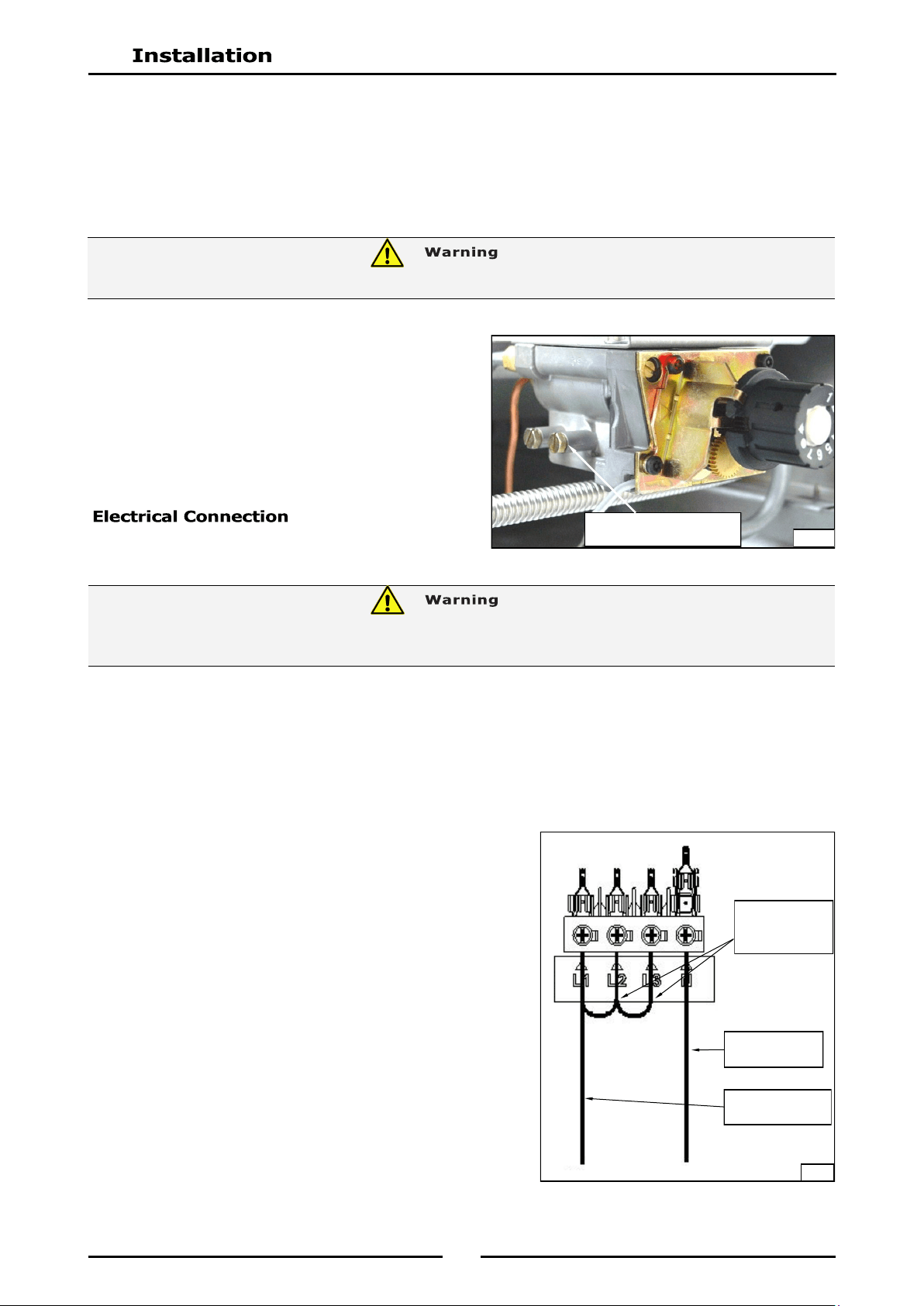
4. Connect the mains supply to L1, L2 and L3 connection
terminals. Refer to the 'Electrical Supply Requirements'
section for connection details.
NOTE: This appliance can be converted from 3 Phase to
Single Phase supply by connecting the single
phase input to L1 and adding a bridge wire
between the L1, L2 and L3 connections, (refer to
Fig 3 opposite and the information shown in the
'Electrical Supply Requirements Table' in the
'Specifications' Section).
Burner Operating Pressure
Test Point (Outlet)
Fig 2
DO NOT USE A NAKED FLAME TO CHECK FOR GAS LEAKAGES.
THIS APPLIANCE MUST BE EARTHED. IF THE SUPPLY CORD IS DAMAGED, IT MUST BE REPLACED BY A
SUITABLY QUALIFIED PERSON IN ORDER TO AVOID A HAZARD.
Add bridging
wires between
L1, L2 and L3.
Phase supply
connection to L1
P
N
Fig 3
Neutral sup-
ply connection
Loading ...
Loading ...
Loading ...