Loading ...
Loading ...
Loading ...
20
NOTE:
Gas conversions should only be carried out by qualified persons. All connections must be
checked for leaks before re-commissioning the appliance.
Adjustment of components that have adjustments / settings sealed (e.g. paint sealed) can
only be adjusted in accordance with the following instructions and shall be re-sealed
before re-commissioning this appliance.
For all relevant gas specifications, refer to ‘Gas Specifications’ table at end of this section.
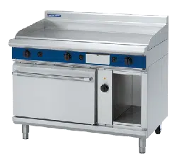
Main Burner Injectors
1. Remove the following:-
Gas control knobs.
Grease Tray
Control Panel.
Disconnect electrical connection lead from rear of piezo igniters.
2. Remove main burner injectors and replace with correct size injectors
as shown in ‘Gas Specifications Tables’ at rear of this section.
3. Ensure that the aeration sleeve is pushed fully ‘IN’ into the burner
and locked in position with the securing screw.
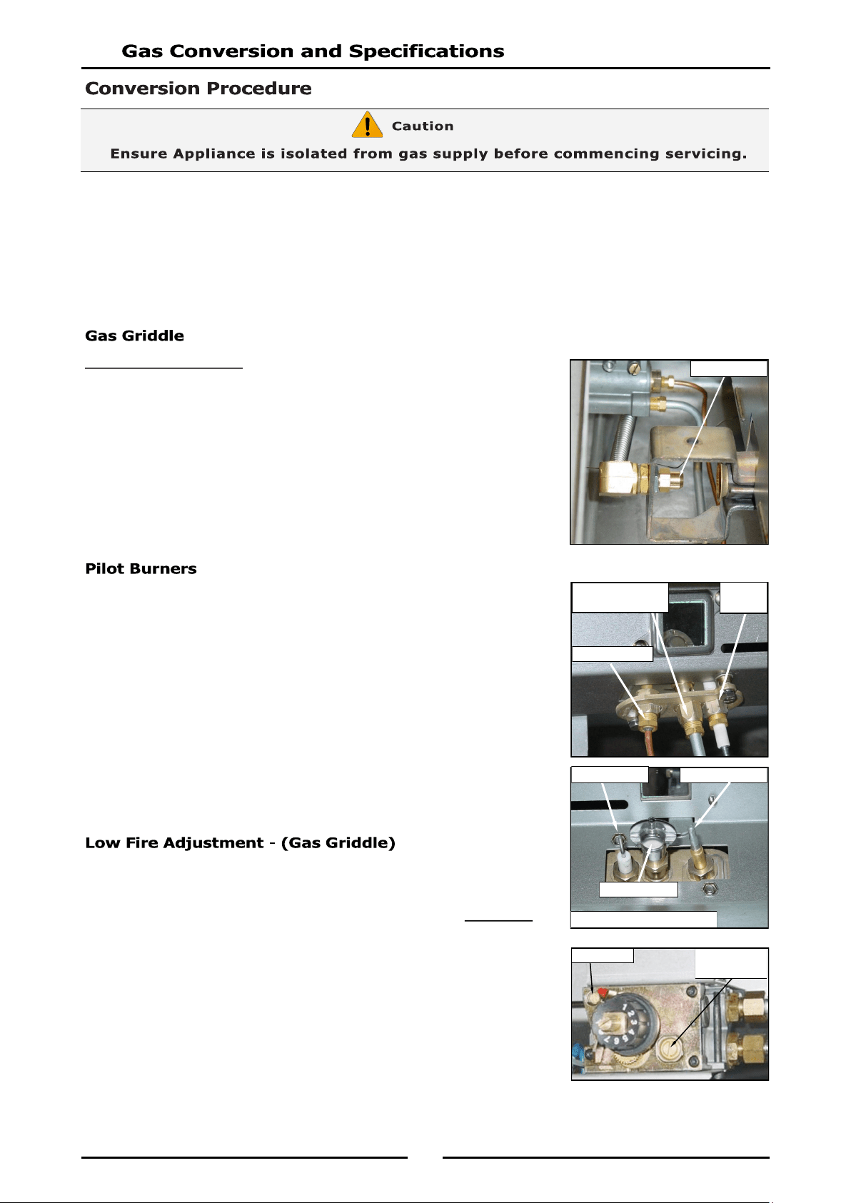
1. Carry out the following:-
Remove the piezo igniter lead.
Unscrew and remove the piezo igniter.
Slacken the gas supply tube at gas control end.
Disconnect gas supply tube to the pilot burner.
2. Remove pilot injector and replace with correct size injector as
shown in the ‘Gas Specifications Tables’ at the rear of this section.
3. Reconnect the following:-
Gas supply tube to pilot burner.
Tighten gas supply tube at gas control end.
Refit piezo igniter.
Re-connect lead to piezo igniter.
To change gas griddle thermostat ‘Low Fire’ adjustment, low fire screw on
gas control valve should be screwed fully in, then un-screwed by 1 full
turn as shown in ‘Gas Specifications’ table at end of this section.
1. Screw ‘Low Fire’ screw fully ‘IN’ and then unscrew by 1 Full Turn of
‘Low Fire’ screw. (Refer to ‘Gas Specification’ table at rear of this
section).
2. Ensure Gas Control Pilot Screw is adjusted to 3 turns out c.c.w.
3. Refit control panel
4. Refit gas control knob.
NOTE: ‘Low Fire Screw’ should be sealed with coloured paint on com-
pletion of low fire adjustment.
Main Injector
Piezo
Igniter
Pilot Injector Gas
Supply Pipe
Thermocouple
Thermocouple
Pilot Injector
Piezo Igniter
Viewed from inside Burner Box
Low Fire
Adjust Screw
Pilot Screw
Loading ...
Loading ...
Loading ...