Loading ...
Loading ...
Loading ...
20 31-5000474 Rev. 1
ENGLISH
Dip Switch Setting
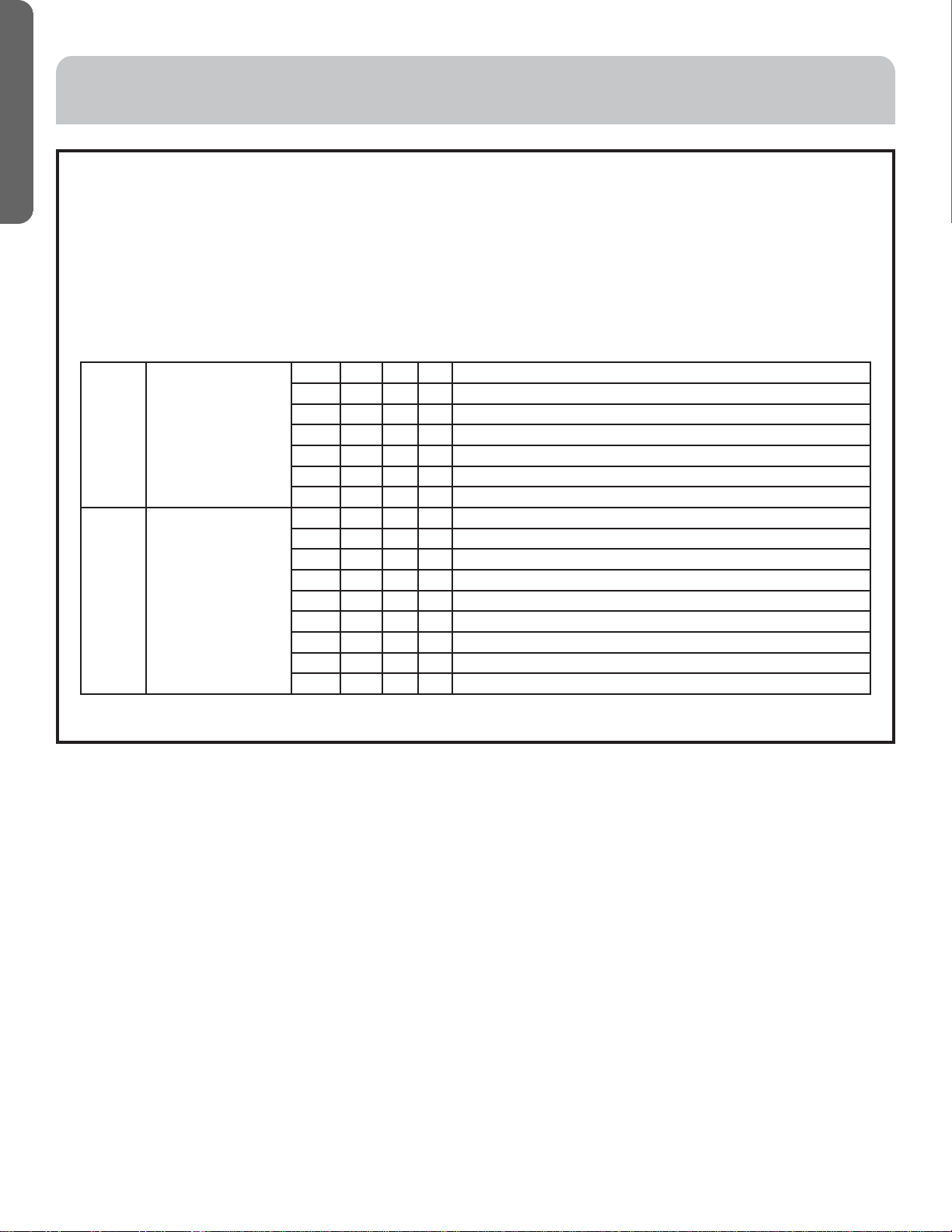
¬Ýëèçìóöúì÷æëìööè÷÷ò÷ëèØñóòöì÷ìòñìéē!Ĕìöìñçìæä÷èçìñ÷ëè÷äåïèÝëèçìóöúì÷æëìööè÷÷ò÷ëèØééóòöì÷ìòñìé ìö
indicated in the table.
• Dip switches set in the factory to on are marked with red.
Definition principles of code switches:
(A) Definition of SW01:
• SW01_1-4 is used to set indoor address when grouping multiple indoor units connected to single wired controller
YRE16B or YR-E17.
• SW01_5-8 set capacity of the indoor unit (factory set). Must only set when replacing board.
Note : A wired controller can be connected to sixteen ultrathin air-duct indoor units maximum.
ELECTRICAL WIRING
SW01_1
SW01_2
SW01_3
SW01_4
Address of wire
controlled indoor unit
(group address)
[1] [2] [3] [4] Address of wire controlled indoor unit (group address)
0 0 0 0 0# (wire controlled main unit) (default)
0 0 0 1 1# (wire controlled sub unit)
0 0 1 1 2# (wire controlled sub unit)
0 0 1 1 3# (wire controlled sub unit)
••• ••• ••• ••• •••• •••
1 1 1 1 15# (wire controlled sub unit)
SW01_5
SW01_6
SW01_7
SW01_8
Capability of indoor unit [5] [6] [7] [8] Capability of indoor unit
0 0 0 1 7000BTU
0 0 1 0 9000BTU
0 0 1 1 12000BTU
0 1 1 0 18000BTU
0 1 1 1 24000BTU
1 0 1 0 36000BTU
1 0 1 1 48000BTU
1 1 0 0 54000BTU
Loading ...
Loading ...
Loading ...