Gas Fired Residential
Floor and Wall Mount
Combi Boilers
Installation
Start-Up
Maintenance
Parts
Warranty
WBRC**140 / 199*
WBRUC**140 / 199* Models
* “F” Denotes Floor Model; “W” Denotes Wall Mount Model, ** “NG” Denotes Natural Gas; “LP” Denotes Propane Gas
This manual must only be used by a qualified service technician. Read all instructions in this manual before installing. Perform
steps in the given order. Failure to do so could result in substantial property damage, severe personal injury, or death.
The manufacturer reserves the right to make product changes or updates without notice and will not be held liable for
typographical errors in literature.
✁ ✂ ✄ ✂ ✁ ☎ ✁ ✆ ✝ ✞ ✄ ✟ ✠ ✡ ☛ ✄ ☞ ✆ ✄ ✌ ✄ ✄ ✡ ☞ ☛ ☛ ✍ ✆ ✂ ✟ ✝ ☎ ✂ ✍ ✁ ✆ ✎ ✁ ✟ ✎ ✝ ✂ ✝ ✟ ✄ ✟ ✄ ✎ ✄ ✟ ✄ ☎ ✄ ✏
www.westinghousewaterheating.com whl-648 Rev. 000 Rel. 003 Date 3.6.18
Improper installation, adjustment, alteration, service, or maintenance could void product warranty and cause property
damage, severe personal injury, or death.
California Proposition 65 Warning: This product contains chemicals known to the State of California to cause cancer, birth
defects, or other reproductive harm.
Heat Exchanger Bears the
ASME “H” Stamp
The surfaces of these products contacted by potable (consumable) water contain less than 0.25% lead by weight as required
by the Safe Drinking Water Act, Section 1417.
whl-648 Rev. 000 Rel. 003 Date 3.6.18
2
The following defined terms are used throughout this manual to
bring attention to the presence of hazards of various risk levels or to
important product information.
DANGER indicates an imminently hazardous situation which, if not
avoided, will result in serious personal injury or death.
WARNING indicates a potentially hazardous situation which, if not
avoided, could result in personal injury or death.
CAUTION indicates a potentially hazardous situation which, if not
avoided, may result in moderate or minor personal injury.
CAUTION used without the safety alert symbol indicates a
potentially hazardous situation which, if not avoided, may result
in property damage.
NOTICE is used to address practices not related to personal injury.
WARNING: If the information in these instructions is not followed exactly, a fire or explosion may result causing property damage, personal
injury or death.
tDo not store or use gasoline or other flammable vapors and liquids in the vicinity of this or any other appliance.
WHAT TO DO IF YOU SMELL GAS
tDo not try to light any appliance.
tDo not touch any electrical switch; do not use any phone in your building.
tImmediately call your gas supplier from a neighbor’s phone. Follow the gas supplier’s instructions.
tIf you cannot reach your gas supplier, call the fire department.
tInstallation and service must be provided by a qualified installer, service agency or the gas supplier.
Improper installation, adjustment, alteration, service, or maintenance can cause injury, property damage, or death. Refer to this
manual. Installation and service must be performed by a qualified installer, service agency, or gas supplier.
whl-648 Rev. 000 Rel. 003 Date 3.6.18
3
Foreword
This manual is intended to be used in conjunction with other
literature provided with the appliance. This includes all related
control information. It is important that this manual, all other
documents included in this system, and additional publications
including the Code for the Installation of Heat Producing Appliances
and National Fuel Gas Code - ANSI Z223.1 (latest versions), be
reviewed in their entirety before beginning any work.
Installation should be made in accordance with the regulations of
the Authority Having Jurisdiction, local code authorities, and utility
companies which pertain to this type of water heating equipment.
Authority Having Jurisdiction (AHJ) – The AHJ may be a federal, state,
local government, or individual such as a fire chief, fire marshal, chief
of a fire prevention bureau, labor department or health department,
building official or electrical inspector, or others having statutory
authority. In some circumstances, the property owner or his/
her agent assumes the role, and at government installations, the
commanding officer or departmental official may be the AHJ.
NOTE: The manufacturer reserves the right to modify product
technical specifications and components without prior notice.
For the Installer
This appliance must be installed by qualified and licensed personnel.
The installer should be guided by the instructions furnished with the
appliance, and by local codes and utility company requirements. In the
absence of local codes, preference should be given to the National Fuel
Gas Code - ANSI Z223.1, latest version.
Installations Must Comply With:
Local, state, provincial, and national codes, laws, regulations, and
ordinances.
The latest version of the National Fuel Gas Code, ANSI Z223.1, from
American Gas Association Laboratories, 8501 East Pleasant Valley
Road, Cleveland, OH 44131.
In Canada - CGA No. B149 (latest version), from Canadian Gas
Association Laboratories, 55 Scarsdale Road, Don Mills, Ontario,
Canada M3B 2R3. Also, Canadian Electrical Code, C 22.1, from Canadian
Standards Association, 5060 Spectrum Way, Suite 100, Mississauga,
Ontario, Canada L4W 5N6.
Code for the Installation of Heat Producing Appliances (latest version)
from American Insurance Association, 85 John Street, New York, NY
11038.
The latest version of the National Electrical Code, NFPA No. 70.
NOTE: The gas manifold and controls met safe lighting and other
performance criteria when undergoing tests specified in ANSI Z21.10.3
- latest edition.
whl-648 Rev. 000 Rel. 003 Date 3.6.18
4
Table of Contents
Part 1 - General Safety Information 5
A. Operation and Installation Warnings 5
B. Improper Combustion 6
C. Gas 6
D. When Servicing the Appliance 7
E. Appliance System 7
F. Water Chemistry Requirements 7
G. Freeze Protection 7
H. Water Temperature Adjustment and Scalding 8
I. High Elevation Installations 8
Part 2 - Before You Start 9
A. What’s in the Box 9
B. Optional Equipment 9
Part 3 - Prepare the Appliance Installation 10
A. Locating the Appliance 10
B. Leveling 10
C. Clearances for Service Access 11
D. Residential Garage and Closet Installations 11
E. Exhaust Vent and Intake Pipe 11
1. Direct Vent of Exhaust and Intake 12
2. Power Venting, Indoor Combustion Air in Confined or Unconfined
Space 12
F. Carbon Monoxide Detectors 12
G. Prevent Combustion Air Contamination 12
H. Removing a Appliance from a Common Vent System 13
I. Technical Specifications 14
J. Wall-Mounting (Wall Mount Models Only) 17
K. Flow Restrictor 18
Part 4 - Water Piping 19
A. General Plumbing Guidelines 19
B. Backflow Preventer 20
C. Expansion Tank 20
D. Piping the Appliance 20
E. Applications 21
G. CH and DHW Pressure Relief Valves 28
The hydronic supply and return connections of these products
are for installation in closed loop systems ONLY! Use of this
product in any manner other than described in this manual may
result in premature product failure, substantial property damage,
severe personal injury, or death. Damage or failure of this product
(or the system in which it is installed) due to unauthorized use IS
NOT COVERED BY WARRANTY.
IMPORTANT
In accordance with Section 325 (f) (3) of the Energy Policy and
Conservation Act, Westinghouse has provided this appliance
with multiple features designed to save energy by reducing the
appliance water temperature as heating load decreases.
These features include:
tA modulating combustion system that adjusts firing rate
based on heat demand.
tAdjustment of appliance set point based on inferred heat
load as determined by an outdoor sensor. The outdoor
sensor is supplied by Westinghouse with this appliance.
tThis appliance does not include a standing pilot.
tThis appliance is designed and shipped to assure the
highest efficiency operation possible. Such high efficiency
is achieved by limiting heating circuit water temperature
to 140°F when there is no anticipated heat load, based
upon the outdoor sensor and the Outdoor Reset Curve
(sensor response curve) in the appliance software.
tThis feature may be over-ridden as described below in
specific installations:
tThe appliance control is equipped with an outdoor sensor
override for use with building management systems or in
cascaded systems (for systems with total input of 300,000
BTU/hr or greater).
See statement below for an important notice on the use of the
override.
IMPORTANT
In accordance with Section 325 (f) (3) of the Energy Policy and
Conservation Act, this appliance is equipped with a feature that
saves energy by reducing the appliance water temperature as
the heating load decreases. This feature is equipped with an
override which is provided primarily to permit the use of an
external energy management system that serves the same
function. THIS OVERRIDE MUST NOT BE USED UNLESS AT LEAST
ONE OF THE FOLLOWING CONDITIONS IS TRUE:
tAn external energy management system is installed that
reduces the appliance water temperature as the heating
load decreases.
tThis appliance is not used for space heating.
tThis appliance is part of a modular or multiple appliance
system having a total input of 300,000 BTU/hr or greater.
tThis appliance is equipped with a tankless coil.
The CSD-1 ASME Code, Section CW-400 requires that hot water
heating and supply appliances have a) a UL 353 temperature
control device, b) at least one (1) temperature-actuated control
to shut off the fuel supply when system water reaches a preset
operating temperature, c) a high temperature limit control that
prevents the water temperature from exceeding the maximum
allowable temperature by causing a safety shutdown and lockout,
and d) its own sensing element and operating switch.
The temperature control system integrated into the 926
control provided with this heating appliance complies with the
requirements of CSD-1 Section CW-400 as a temperature operation
control. The control monitors the temperature difference between
the inlet and the outlet sensor, which is affected by appliance water
flow. If this temperature difference exceeds 55°F (typically because
of low water flow or very low heat load), the control will reduce
the maximum fan speed. If the temperature difference exceeds
60°F, the control will effectively sense there is little or no water
flow or heat load and shut the appliance down. The controller
will restart automatically once the temperature difference has
dropped below 55°F and the minimum off time (anti-cycle time)
has expired. In addition, if the control senses that the outlet water
temperature has reached 210°F, the appliance is put into a hard
lockout and requires manual reset to restart.
whl-648 Rev. 000 Rel. 003 Date 3.6.18
5
Part 5 - Venting 29
A. General 29
B. Approved Materials for Exhaust Vent and Intake Pipe 30
C. Additional Requirements for Installation in Canada 30
D. Exhaust Vent and Intake Pipe Location 31
E. Exhaust Vent and Intake Pipe Sizing 32
F. Tightening Appliance Collar to Exhaust Vent and Intake Pipe 32
G. Exhaust Vent and Intake Pipe Installation 32
H. Applications 33
1. Direct Vent Installation of Exhaust and Intake 33
2. Venting Through an Existing System 36
3. Power Venting, Indoor Combustion Air in Confined or Unconfine
Space 37
Part 6 - Installing the Condensate Drain 38
Part 7 - Connecting Electrical Service 39
A. Wiring 39
B. Dip Switches 39
Part 8 - Gas Connections 44
A. Gas Pipe Sizing Tables 44
1. Gas Pipe Sizing 44
2. Natural Gas Pipe Sizing 44
3. LP (Liquid Propane) Gas Pipe Sizing 44
B. Gas Connection Requirements 44
C. Additional Precaution for Excess Flow Valve (EFV) 45
D. Checking Gas Pressure at the Appliance for Proper Operation
45
E. Setting and Verifying the Combustion Setting 45
Part 9 - Controls 46
A. Control and Display Overviews 46
B. Start-Up Sequence 46
C. Changing the DHW Set-Point 47
D. Changing the Temperature Indicator 47
E. Changing the CH Set-Point 47
F. Storage Mode 47
G. Lock Function 47
H. Status Display 48
I. Installer Mode 49
J. Outdoor Temperature Mode (Optional) 50
K. 0-10 Volt Input 51
Part 10 - Troubleshooting 52
A. Error Code 52
B. Error Tree Analysis 55
1. Flame Detection 55
2. Air Pressure Switch / Burner Overheat Limit / Condensate Block Switch
55
3. DHW / Operating Temperature / CH Overheat / Exhaust Sensors 55
C. Suggested Corrective Actions 56
Part 11 - Start-Up 58
A. Check / Control Water Chemistry 58
B. Check for Gas Leaks 58
C. Freeze Protection (When Used) 59
D. Fill and Test Water System 59
E. Purge Air from CH and Internal Storage Tank 59
F. Purge Air from DHW System 60
G. Check Thermostat Circuit(s) 60
H. Condensate Removal 60
Part 12 - Installation Checklist 61
Part 13 - Maintenance 62
Part 14 - Moving Adapters from Left to Right (Floor Models) 67
Part 15 - Replacement Parts 67
Limited Warranty for WBRC Appliances 77
Notes 79
Customer Installation Record Form 80
Part 1 - General Safety Information
This appliance is approved for indoor installations only and is not
intended for use as a pool heater. Clearance to combustible materials:
0” top, bottom, sides, and back. Appliance must have room for service:
24” front, 18” top, 12” bottom, and 0” back are minimum recommended
service clearances. Minimum recommended side clearances depend
on model and installation options. (A combustible door or removable
panel is acceptable front clearance. A 3” minimum clearance must
be provided from the appliance front cover to the removable panel
or combustible door.) This appliance has been approved for closet
installation and installation on combustible flooring. Do not install
directly on carpeting. Install the appliance in a location where relief
valve discharge or a leak will not result in damage to the surrounding
area. If such a location is not available, install an auxiliary catch pan.
The appliance is rated Category IV (pressurized vent, likely to form
condensate in the vent) and requires a special vent system designed
for pressurized venting. Use only Category IV vent systems.
Installer - Read all instructions in this manual before installing.
Perform steps in the given order.
User - This manual is for use only by a qualified service technician.
Have this appliance serviced / inspected annually by a qualified
service technician.
FAILURE TO ADHERE TO THE GUIDELINES ON THIS PAGE
CAN RESULT IN SUBSTANTIAL PROPERTY DAMAGE, SEVERE
PERSONAL INJURY, OR DEATH.
NOTE: Obey all local codes. Obtain all applicable permits before
installing the appliance.
NOTE: Install all system components and piping in such a manner
that does not reduce the performance of any fire rated assembly.
A. Operation and Installation Warnings
To avoid serious injury or death, read, understand, and follow all of the
precautions listed here.
Vapors from flammable liquids will explode and can cause a fire,
resulting in personal injury or death. The appliance has a burner
that can come on at any time and ignite vapors. DO NOT use or store
flammable liquids around the appliance.
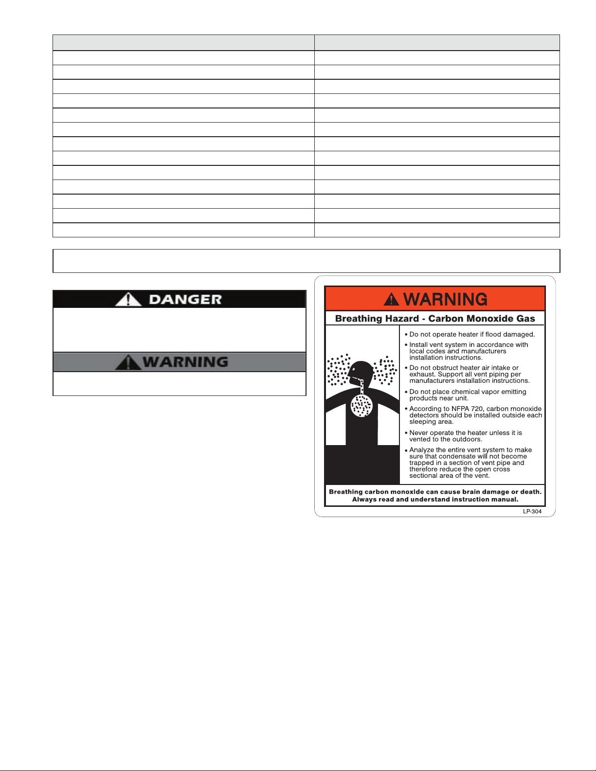
Improper venting can cause a build-up of carbon monoxide.
Breathing carbon monoxide can result in brain damage or death. DO
NOT operate the appliance unless it is properly vented to the outside
and has an adequate fresh air supply for safe operation. Inspect the
exterior exhaust gas outlet port and fresh air inlet port on a regular
basis to ensure they are functioning properly.
A concentration of carbon monoxide as small as .04% (400 parts
per million) in the air can be fatal. When making high fire or low
fire adjustments, CO levels must be monitored using a calibrated
combustion analyzer such that a CO level of no more than 150 ppm
is exceeded at any time during operation.
Adjusting the “low fire offset” or the “main flow restrictor” in small
increments can result in a significant increase in CO concentration.
To avoid serious injury or death, DO NOT make any adjustments
to the gas valve without monitoring the exhaust gases with a fully
functional and calibrated combustion analyzer.
Failure to follow these instructions will result in property damage,
severe personal injury, or death.
whl-648 Rev. 000 Rel. 003 Date 3.6.18
6
This appliance must be installed by a qualified service technician.
Improper installation and/or operation can cause a potentially
hazardous situation, which, if not avoided, could result in serious
injury or death, and will void the warranty.
The manufacturer cannot anticipate every circumstance that
might involve a potential hazard. Each installation has its own
specialized characteristics, requirements, and possible hazards.
Therefore, all possible incidents are not included in these
warnings. Proper and safe installation, operation, and service are
the responsibility of the qualified service technician.
Proper care of the appliance is the user’s responsibility. Ensure
the user carefully reads and understands the User’s Information
Manual before operating and maintaining the appliance.
Make sure the user knows the location of the gas shut-off valve
and how to operate it. Immediately close the gas shut-off valve
if the appliance is subjected to fire, overheating, flood, physical
damage, or any other damaging condition that might affect the
operation of the unit. Have the appliance checked by a qualified
technician before resuming operation.
Do not power up the unit unless the gas and water supply valves
are fully opened. Make sure the fresh air intake port and exhaust
gas port are open and functional.
No one but a qualified service technician should attempt to install,
service, or repair this appliance. There are no serviceable parts
which can be changed by the user / owner. User / Owner: Contact
the original qualified service technician if the appliance needs
repair or maintenance. If the original technician is unavailable, ask
your gas supplier for a list of qualified service providers.
Keep the area around the appliance clean and free of all materials
that can burn. DO NOT store or place gasoline, oils, spray paint, or
other flammable products near the appliance.
DO NOT use spray paint, hair spray, or any other flammable spray
near the appliance or near the exterior fresh air intake port. DO
NOT place any items in or around the exterior exhaust gas outlet
port and/or fresh air inlet port that could restrict or block the flow
in or out of the vent system.
DO NOT store or place newspapers, laundry, or other combustible
items near the appliance or the exterior exhaust gas outlet and/or
fresh air inlet port.
After installation, all appliance safety devices should be tested.
This appliance is certified for indoor installations only. The
appliance consists of gas ignition system components which
must be protected from water (dripping, spraying, etc.) during
operation and service. Carefully consider installation location and
the placement of critical components (circulators, condensate
neutralizers, etc.) before installing the appliance.
DO NOT allow children to operate this unit. DO NOT use this unit if
it does not appear to be operating correctly. A qualified technician
should service and inspect the appliance annually.
This appliance is equipped with a three prong plug. It should only be
plugged directly into a properly grounded three prong receptacle.
DO NOT remove the ground plug from the plug.
Any claims for damage or shortage in shipment must be filed
immediately against the transportation company by the consignee.
This appliance provides a overheat shutdown limit. In the event the
appliance water temperature exceeds the set point of the control
limit, the cutoff will trip and the appliance will shut down. Certain
local codes require additional temperature limits. In addition, certain
types of systems may operate at temperatures below the minimum
set point of the limit provided with the appliance. Contact the
manufacturer for additional overheat controls.
NOTE: When inquiring about service or troubleshooting, reference the
model and serial numbers from the appliance rating label.
The owner should inspect the system monthly for damage, water
stains, signs of rust, corrosion, and exhaust vent and air intake
blockage. If inspection of the unit shows signs of damage, the
appliance should be shut off until the problem is repaired by a
qualified technician.
DO NOT USE THIS APPLIANCE IF ANY PART HAS BEEN
SUBMERGED IN WATER. Immediately call a qualified service
technician. The appliance MUST BE replaced if it has been submerged.
Attempting to operate a appliance that has been submerged could
create numerous harmful conditions, such as a potential gas leakage
causing a fire and/or explosion, or the release of mold, bacteria,
or other harmful particulates into the air. Operating a previously
submerged appliance could result in property damage, severe
personal injury, or death.
NOTE: Appliance damage due to flood or submersion is considered
an Act of God, and IS NOT covered under product warranty.
NOTE: If the appliance is exposed to the following, do not operate.
Immediately call a qualified service technician.
1. Fire
2. Damage
3. Water
Failure to follow this information could result in property damage,
severe personal injury, or death.
DO NOT alter or modify the appliance or appliance controls. Altering
any Westinghouse appliance with parts not manufactured by
Westinghouse WILL INSTANTLY VOID the appliance warranty and
could result in property damage, personal injury, or death.
Do not use this appliance for anything other than its intended
purpose (as described in this manual). Doing so could result in
property damage and WILL VOID product warranty.
B. Improper Combustion
Do not obstruct the flow of combustion and ventilating air. Adequate
air is necessary for safe operation. Failure to keep the exhaust vent
and combustion air intake clear of ice, snow, or other debris could
result in property damage, serious personal injury, or death.
C. Gas
Should overheating or gas supply fail to shut off, turn off the manual
gas control valve to the appliance.
Due to the low water content of the appliance, improper sizing of the
appliance with regard to heating system load will result in excessive
cycling and accelerated component failure. Westinghouse DOES NOT
warrant failures caused by improperly sized appliance applications.
DO NOT oversize the appliance to the system. Modular appliance
installations greatly reduce the likelihood of appliance oversizing.
whl-648 Rev. 000 Rel. 003 Date 3.6.18
7
D. When Servicing the Appliance
tTo avoid electric shock, disconnect electrical supply before
performing maintenance.
tTo avoid severe burns, allow appliance and associated
equipment to cool before servicing.
tDo not use petroleum-based cleaning or sealing compounds
in an appliance system. Gaskets and seals in the system may
be damaged. This can result in substantial property damage.
tDo not use “homemade cures” or “patent medicines”.
Damage to the appliance, substantial property damage,
and/or serious personal injury may result.
tAlways verify proper operation after servicing the appliance.
NOTE: When inquiring about service or troubleshooting, reference
the model and serial numbers from the appliance rating label.
Be sure to disconnect electrical power before opening appliance
cabinet or performing service. Label all wires while performing
service to ensure proper re-wiring of the appliance. Wiring errors
can cause improper or dangerous operation. Failure to do so
could result in an electrical shock, improper appliance operation,
property damage, serious personal injury, or death.
F. Water Chemistry Requirements
Chemical imbalance of the water supply may affect efficiency and
cause severe damage to the appliance and associated equipment.
Water quality must be professionally analyzed to determine
whether it is necessary to treat the water. Various solutions are
available to adjust water quality. Adverse water quality will affect
the reliability of the system. In addition, operating temperatures
above 135
o
F will accelerate the build-up of lime scale and possibly
shorten appliance service life. Failure of an appliance due to
lime scale build-up, low pH, or other chemical imbalance IS NOT
covered by the warranty.
The water must be potable, free of corrosive chemicals, sand,
dirt, and other contaminates. It is up to the installer to ensure the
water does not contain corrosive chemicals or elements that can
damage the heat exchanger. Potable water is defined as drinkable
water supplied from utility or well water in compliance with EPA
secondary maximum contaminant levels (40 CFR Part 143.3). If
the water contains contaminants higher than outlined by the EPA,
water treatment is recommended and additional, more frequent
maintenance may be required. See Table 1.
Contaminant Maximum Allowable Level
Total Hardness
(Residential Use - Below 140
o
F
water temperature)
200 mg/l
(12 grains/gallon)
Total Hardness
(Commercial Use - Above 140
o
F
water temperature)
120 mg/l
(7 grains/gallon)
Aluminum 0.05 to 0.2 mg/l or PPM
Chloride 100 mg/l or PPM
Copper 1 mg/l or PPM
Iron 0.3 mg/l or PPM
Manganese 0.05 mg/l or PPM
pH 6.5 - 8.5
Sulfate 205 mg/l or PPM
Total Dissolved Solids (TDS) 500 mg/l or PPM
Zinc 5 mg/l or PPM
Dissolved Carbon Dioxide (CO2) 15 mg/l or PPM
Table 1 - Water Quality Specifications
G. Freeze Protection
The appliance control is equipped with freeze protection that activates
based on internal water temperature. See the table below for details
on freeze protection operation.
NOTE: Freeze protection will not be active if the appliance loses power.
Consider piping and installation when determining appliance
location. Damages resulting from incorrect installation or from use
of products not approved by the manufacturer ARE NOT covered by
warranty.
NEVER use any toxic chemical, including automotive, standard glycol
antifreeze, or ethylene glycol made for hydronic (non-potable)
systems. These chemicals can attack gaskets and seals in water
systems, are poisonous if consumed, and can cause personal injury
or death.
System
Freeze
Protection
(Activates
Based on
Internal
Water
Temperature)
Freeze Protection Operation Range
Stage 1 - If control detects water
temperature of 46
o
F (8
o
C) and below, it
turns the internal and external pumps
On for 600 seconds and Off for 30
seconds. This cycle repeats until the
control detects inlet water temperature
of 50
o
F (10
o
C) and above.
ON or OFF
(Default: ON)
NOTE:
If using
appliance for
Snow Melt
applications,
turn Freeze
Protection
OFF.
Stage 2 - If control detects water
temperature of 41
o
F (5
o
C) and below,
it turns the burner on to meet a target
temperature of 104
o
F (40
o
C). The burner
and internal and external pumps will
continuously during this stage until the
control detects inlet water temperature
of 104
o
F (40
o
C) and above.
Stage 3 - If control detects water
temperature of 34
o
F (1
o
C) and below,
Er: 85 will appear on the display.
Table 2 - Freeze Protection Detail
E. Appliance System
tThoroughly flush the system (without the appliance
connected) to remove sediment. The high efficiency heat
exchanger can be damaged by build-up or corrosion due to
sediment. The manufacturer recommends a suction strainer
in all systems.
tDo not use petroleum-based cleaning or sealing compounds
in a appliance system. Gaskets and seals in the system may
be damaged. This can result in substantial property damage.
tDo not use “homemade cures” or “patent medicines”.
Damage to the appliance, substantial property damage,
and/or serious personal injury may result.
Continual fresh make-up water will reduce appliance life. Mineral
buildup in the heat exchanger reduces heat transfer, overheats
the stainless steel heat exchanger, and causes failure. Addition of
oxygen from make-up water can cause internal corrosion in system
components. Leaks in the appliance or piping must be repaired at
once.
If you suspect that your water is contaminated in any way, discontinue
use of the appliance and contact an authorized technician or licensed
professional.
whl-648 Rev. 000 Rel. 003 Date 3.6.18
8
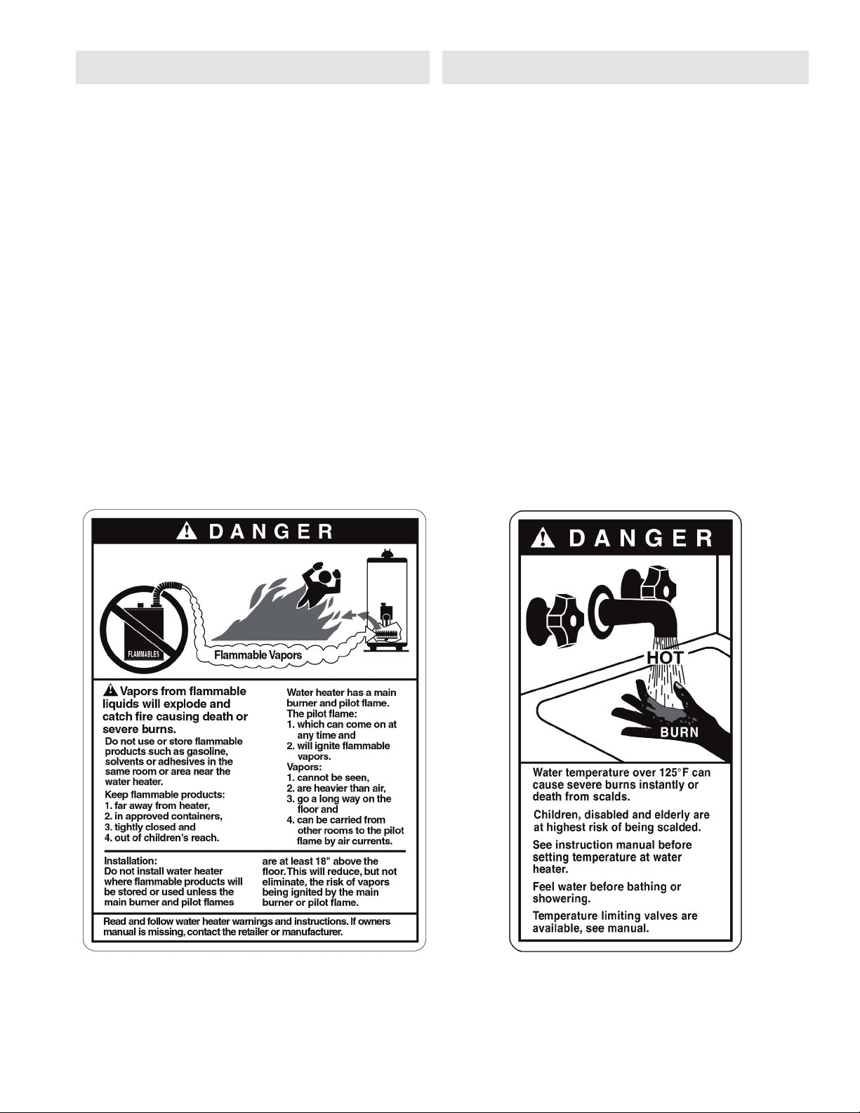
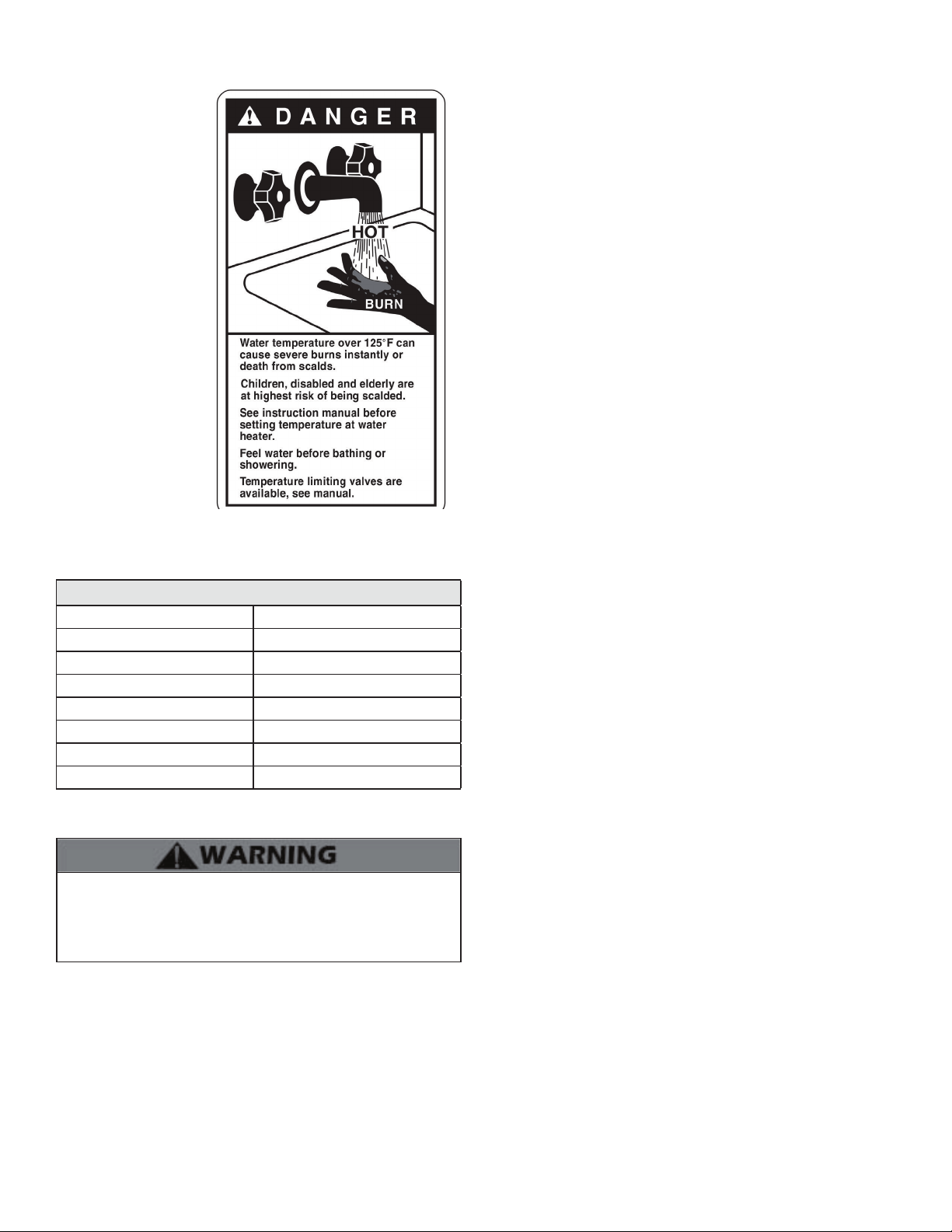
H. Water Temperature Adjustment and Scalding
This appliance can deliver
scalding water. Be careful
whenever using hot
water to avoid scalding
injury. Certain appliances
such as dishwashers and
automatic clothes washers
may require increased
water temperatures. By
setting the thermostat
on this heater to obtain
the increased water
temperature required by
these appliances you may
create the potential for
scald injury.
To protect against injury,
install a mixing valve in the
water system. This valve
will reduce point of use
discharge temperatures
by mixing cold and hot
water in branch supply
lines. Such valves are
available from your local
plumbing supplier.
Table 3 details the relationship of water temperature and time with
regard to scald injury and may be used as a guide in determining the
safest water temperature for your applications.
Approximate Time / Temperature Relationships in Scalds
120
o
F More than 5 minutes
125
o
F 1 1/2 to 2 minutes
130
o
F About 30 seconds
135
o
F About 10 seconds
140
o
F Less than 5 seconds
145
o
F Less than 3 seconds
150
o
F About 1 1/2 seconds
155
o
F About 1 second
Table 3 - Time and Temperature Relationship in Scalds
I. High Elevation Installations
Natural gas at high elevation might contain less heating value than
typical 1,000 BTU/cu ft and therefore can cause improper air / gas
mix leading to improper combustion. For natural gas installations
above 3,000 ft, call your gas provider to determine the heating value
of the supplied natural gas.
whl-648 Rev. 000 Rel. 003 Date 3.6.18
9
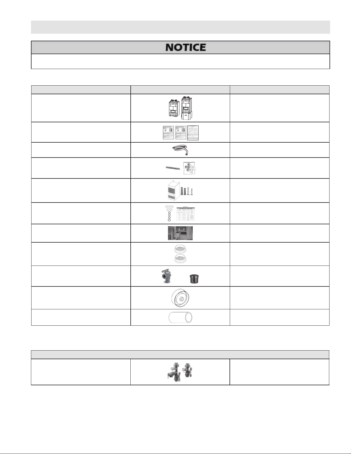
Components included with the appliance:
A. What’s in the Box
Item Description Quantity
Universal Fire Tube Combination Appliance
One (1) Floor or Wall Mounted Appliance
User and Installation Manuals,
H2 Document
One (1) each
Condensate Hose (Wall Mount Only)
(Part # - 7855P-089)
One (1)
Anchors and Wall Mounting Bracket
(Wall Mount Only)
(7850P-084)
One (1) Kit
Outdoor Sensor with
Screws and Anchors
(7855P-084)
One (1)
Spare Parts Kit
(Gaskets and O-Rings)
(7855P-258)
One (1)
LP Conversion Kit
(199 Model ONLY - 7855P-452)
One (1)
Vent Screens (3”)
(7850P-085)
Two (2) screens
CH 30 PSI Pressure Relief Valve and
3/4” x 1” Bushing
(7855P-077)
One (1)
Blue Flow Restrictor
(Limits Flow to 4.5 GPM - 140 Model Only)
(7855P-260)
One (1) Each
Combi Venting Kit
(S7855-002)
One (1)
Table 4 - Included with the Appliance
UNCRATING THE APPLIANCE - Any claims for damage or shortage in shipment must be filed immediately against the transportation
company by the consignee.
Part 2 - Before You Start
Open the shipping crate of the appliance.
B. Optional Equipment
Optional equipment available from Westinghouse (and Part #):
Optional Parts
Threaded 3/4” DHW Tankless Isolation
Valves (w/ Pressure Relief Valve)
(7850P-090)
1
Table 5 - Optional Equipment
Other Optional Equipment
Below is a list of other optional equipment available from
Westinghouse. These additional options may be purchased through
your Westinghouse distributor:
t2” PVC Concentric Vent Kit (Part # KGAVT0501CVT)
t3” PVC Concentric Vent Kit (Part # KGAVT0601CVT)
t2” Stainless Steel Outside Termination Vent Kit (Part # V500)
t3” Stainless Steel Outside Termination Vent Kit (Part # V1000)
t4” Stainless Steel Outside Termination Vent Kit (Part # V2000)
t6” Stainless Steel Outside Termination Vent Kit (Part # V3000)
t3” Polypro Vent Kit (Part # 8400P-001)
t3” Polypro Pipe (33’ length Part # 8400P-002, 49.5’ length Part
# 8400P-003)
tCondensate Neutralizer (Part # 7450P-212)
whl-648 Rev. 000 Rel. 003 Date 3.6.18
10
Part 3 - Prepare the Appliance Installation
Remove all sides of the shipping crate to allow the appliance to be
moved into its installation location.
COLD WEATHER HANDLING - If the appliance has been stored in
a very cold location (BELOW 0
o
F) before installation, handle with
care until the components come to room temperature. Failure to
do so could result in damage to the appliance.
Carefully consider installation when determining appliance
location. Please read the entire manual before attempting
installation. Failure to properly take factors such as venting,
piping, condensate removal, and wiring into account before
installation could result in wasted time, money, and possible
property damage and personal injury.
This appliance is certified for indoor use only. DO NOT INSTALL
OUTDOORS. Outdoor installations ARE NOT covered by warranty.
Failure to install the appliance indoors could result in property
damage, severe personal injury, or death.
A. Locating the Appliance
Incorrect ambient conditions can lead to damage to the heating
system and put safe operation at risk. Ensure that the installation
location adheres to the information included in this manual. Failure
to do so could result in property damage, serious personal injury,
or death. Failure of appliance or components due to incorrect
operating conditions IS NOT covered by product warranty.
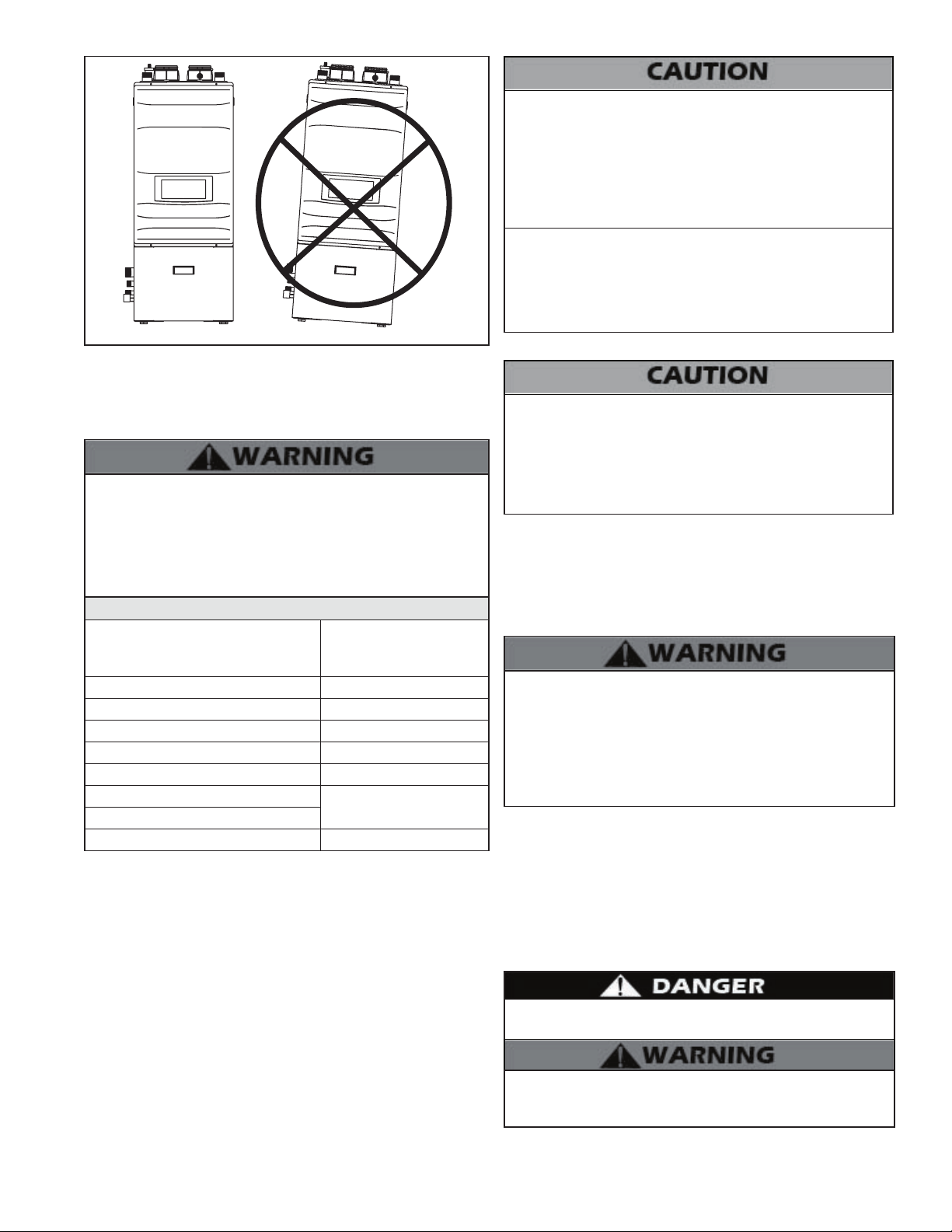
This appliance must be installed upright in the vertical position as
described in this manual. DO NOT attempt to install this appliance
in any other orientation. Doing so will result in improper appliance
operation and property damage, and could result in serious
personal injury or death.
1. Installation Area (Mechanical Room) Operating Conditions
tEnsure ambient temperatures are higher than 32
o
F / 0
o
C and
lower than 104
o
F / 40
o
C
tPrevent the air from becoming contaminated by the
products, places, and conditions listed in this manual
tAvoid continuously high levels of humidity
tNever close existing ventilation openings
tEnsure a minimum 1” clearance around hot water and
exhaust vent pipes
tNOTE: To prevent condensing in the fan, it is recommended
to avoid prolonged exposure to temperatures below 45
o
F
This appliance has a condensate disposal system that may freeze
if exposed to sustained temperatures below 32
o
F. Precautions
should be taken to protect the condensate trap and drain lines
from sustained freezing conditions.
The service life of the appliance’s exposed metallic surfaces,
such as the casing, as well as internal surfaces, such as the heat
exchanger, are directly influenced by proximity to damp and salty
marine environments. In such areas higher concentration levels of
chlorides from sea spray coupled with relative humidity can lead
to degradation of appliance components. In these environments,
appliances must not be installed using direct vent systems which
draw outdoor air for combustion. Such appliances must be installed
using room air for combustion. Indoor air will have a much lower
relative humidity, and hence potential corrosion will be minimized.
2. Check for nearby connections to:
tSystem water piping
tVenting connections
tGas supply piping
tElectrical power
tCondensate drain
Locate the appliance where any leakage from the relief valve, related
piping, tank, or connections will not result in damage to surrounding
areas or lower floors of the building. The appliance should be located
near a floor drain or installed in a drain pan. Leakage damages ARE
NOT covered by warranty.
3. Check area around appliance. Remove any combustible materials,
gasoline, and other flammable liquids.
Failure to keep the appliance area clear and free of combustible
materials, liquids, and vapors can result in substantial property
damage, severe personal injury, or death.
4. Gas control system components must be protected from dripping
water during operation and service.
5. If the appliance is to replace an existing appliance, check for and
correct any existing system problems, such as:
tSystem leaks
tLocation that could cause the system and appliance to freeze
and leak
tIncorrectly sized expansion tank
6. Clean and flush system when reinstalling an appliance.
tCondensate Removal Pump (Part # 554200)
t2” Mesh Vent Screens (Part # 7850P-088)
tUL353 Low Water Cut-Off Kit (Part # 7855P-315)
NOTE: When using an optional system sensor, pipe insulation
must be wrapped around it to improve temperature measurement
accuracy and increase overall system efficiency.
Do not introduce toxic chemicals, such as antifreeze or appliance
treatments, into any piping meant for potable water purposes.
B. Leveling
In order for the condensate to properly flow out of the collection
system, the area where you locate the appliance must be level.
Location must also fully support the weight of the filled appliance.
NOTE: When installing in a zero clearance location, it may not be
possible to read or view some product labeling. It is recommended to
make note of the appliance model and serial number.
Do not connect the appliance DHW connections to any heating
systems or components that have been previously used for non-
potable applications.
Ensure that all piping and components connected to the appliance
are suitable for potable water applications.
Do not use this appliance only for space heating applications.
Circulators suitable for DHW applications must be used.
Failure to take precautions could result in property damage,
severe personal injury, or death.
whl-648 Rev. 000 Rel. 003 Date 3.6.18
11
C. Clearances for Service Access
The space must be provided with combustion / ventilation air
openings correctly sized for all other appliances located in the same
space as the appliance. The appliance cover must be securely fastened
to prevent the appliance from drawing air from the appliance room.
This is particularly important if the appliance is in a room with other
appliances. Failure to comply with the above warnings could result
in substantial property damage, severe personal injury, or death.
See Table 5 for recommended service clearances. If these minimum
clearances are not provided, it may not be possible to service the
appliance without removing it from the space.
Minimum Clearances
Installation Clearances from Non-
Combustibles / Combustibles
Recommended Service
and Proper Operation
Clearances
Top 18” (45.7 cm)
Back 0” (0 cm)
Bottom (Wall Mount Model) 12” (30.45 cm)
Bottom (Floor Model) 0” (0 cm)
Front 24” (60.9 cm)
Right or Left Side (Wall Mount Model)
3” (7.6 cm)
*Side without Adapters (Floor Model)
*Adapter Side (Floor Model) 24” (60.96 cm)
Table 6 - Minimum Installation and Service Clearances - *NOTE: The piping
configuration of the Floor Model can be changed from the left to the right side
of the appliance.
NOTE: For closet installations, a combustible door or removable
panel is acceptable front clearance. A 3” minimum clearance must be
provided from the appliance front cover to the removable panel or
combustible door.
NOTE: If you do not provide the minimum clearances shown in Table
5 it might not be possible to service the appliance without removing
it from the space.
All appliances eventually leak. It is recommended to install a catch
pan beneath the appliance. This catch pan should be sized with a
maximum depth of 2”, and a minimum diameter 2” greater than
the diameter of the appliance. The catch pan should empty into
an open drain line. This drain line should be 3/4” ID minimum,
piped to an open drain. Failure to follow these instructions could
result in property damage. Such damages ARE NOT covered by
product warranty.
MINIMUM CLEARANCES FROM COMBUSTIBLE MATERIALS
tHot water pipes - at least 1” from combustible materials
tExhaust vent pipe - at least 1” from combustible materials
Always take future maintenance into consideration when
locating the appliance. If the appliance is located in an installation
location with limited clearances, it may be necessary to remove
the appliance from the space to perform maintenance. Failure
to consider maintenance when determining installation location
could result in property damage.
D. Residential Garage and Closet Installations
Precautions
If the appliance is located in a residential garage, per ANSI Z223.1:
tMount the bottom of the appliance a minimum of 18” above
the floor of the garage to ensure the burner and ignition
devices are well off the floor.
tLocate or protect the appliance so it cannot be damaged by
a moving vehicle.
Check with your local Authority Having Jurisdiction for
requirements when installing the appliance in a garage or closet.
Please read the entire manual before attempting installation.
Failure to properly take factors such as venting, piping, condensate
removal, and wiring into account before installation could result
in wasted time, money, and possible property damage and
personal injury.
The space must be provided with correctly sized combustion/
ventilation air openings for all other appliances located in the
space with the appliance. For power venting installations using
room air for combustion, refer to the venting section, this manual,
for descriptions of confined and unconfined spaces. Do not install
the appliance in an attic. Failure to comply with these warnings
could result in substantial property damage, severe personal
injury, or death.
E. Exhaust Vent and Intake Pipe
The appliance is rated Category IV (pressurized vent, likely to form
condensate in the vent) and requires a special vent system designed
for pressurized venting.
NOTE: The venting options described here (and further detailed
in the Venting section, this manual) are the lone venting options
approved for this appliance. Failure to vent the appliance in
accordance with the provided venting instructions will void the
warranty.
Failure to vent the appliance properly will result in serious personal
injury or death.
Do not attempt to vent this appliance by any means other than
those described in this manual. Doing so will void the warranty
and may result in severe personal injury or death.
Correct Installation
Incorrect Installation
Figure 1 - Leveled Appliance (Floor Model)
whl-648 Rev. 000 Rel. 003 Date 3.6.18
12
The exhaust discharged by this appliance may be very hot. Avoid
touching or other direct contact with the exhaust gases of the vent
termination assembly. Doing so could result in severe personal
injury or death.
Vents must be properly supported. Appliance exhaust and intake
connections are not designed to carry heavy weight. Vent support
brackets must be within 1’ of the appliance and the balance at 4’
intervals. Appliance must be readily accessible for visual inspection
for first 3’ from the appliance. Failure to properly support vents
could result in property damage, severe personal injury, or death.
1. Direct Vent of Exhaust and Intake
If installing a direct vent option, combustion air must be drawn
from the outdoors directly into the appliance intake and exhaust
must terminate outdoors. There are three basic direct vent options
detailed in this manual: 1. Side Wall Venting, 2. Roof Venting, and 3.
Unbalanced Venting.
Be sure to locate the appliance such that the exhaust vent and intake
piping can be routed through the building and properly terminated.
Different vent terminals can be used to simplify and eliminate
multiple penetrations in the building structure (see Optional
Equipment in Venting Section). The exhaust vent and intake piping
lengths, routing, and termination methods must all comply with the
methods and limits given in the Venting Section, this manual.
When installing a combustion air intake from outdoors, care must
be taken to utilize uncontaminated combustion air. To prevent
combustion air contamination, see Table 6.
2. Power Venting, Indoor Combustion Air in Confined or
Unconfined Space
This appliance requires fresh, uncontaminated air for safe operation
and must be installed in a mechanical room where there is adequate
combustion and ventilating air. NOTE: To prevent combustion air
contamination, see Table 6.
Combustion air from the indoor space can be used if the space has
adequate area or when air is provided through a duct or louver
to supply sufficient combustion air based on the appliance input.
Never obstruct the supply of combustion air to the appliance. If the
appliance is installed in areas where indoor air is contaminated (see
Table 6) it is imperative that the appliance be installed as direct vent
so that all combustion air is taken directly from the outdoors into the
appliance intake connection.
Unconfined space is space with volume greater than 50 cubic feet
per 1,000 BTU/hr (4.8 cubic meters per kW) of the total input rating of
all fuel-burning appliances installed in that space. Rooms connected
directly to this space through openings not furnished with doors are
considered part of the space. See Venting Section for details.
Confined space is space with volume less than 50 cubic feet per
1,000 BTU/hr (4.8 cubic meters per kW) of the total input rating of all
fuel-burning appliances installed in that space. Rooms connected
directly to this space through openings not furnished with doors are
considered part of the space.
When drawing combustion air from inside a conventionally
constructed building to a confined space, such space should be
provided with two permanent openings: one located 6” (15cm)
below the space ceiling, the other 6” (15cm) above the space floor.
Each opening should have a free area of one square inch per 1,000
BTU/hr (22cm
2
/kW) of the total input of all appliances in the space,
but not less than 100 square inches (645cm
2
).
If the confined space is within a building of tight construction, air for
combustion must be obtained from the outdoors as outlined in the
Venting section of this manual.
When drawing combustion air from the outside into the mechanical
room, care must be taken to provide adequate freeze protection.
Failure to provide an adequate supply of fresh combustion air can
cause poisonous flue gases to enter the living space, resulting
in severe personal injury or death. To prevent combustion air
contamination, see Table 6.
In the Commonwealth of Massachusetts and As Required by State
and Local Codes:
Installation of Carbon Monoxide Detectors: At the time of installation
or replacement of the vented gas fueled appliance, the installing
plumber or gas fitter shall observe that a hard wired carbon monoxide
detector with an alarm and battery back-up is installed on the floor
level where the gas appliance is installed, unless the appliance is
located in a detached, uninhabitable structure separate from the
dwelling, building, or structure used in whole or in part for residential
purposes.
In addition, the installing plumber or gas fitter shall observe that a hard
wired carbon monoxide detector with an alarm and battery back-up is
installed on each additional level of the dwelling, building, or structure
served by the vented gas appliance. It shall be the responsibility of the
property owner to secure the service of qualified licensed professionals
for the installation of hard wired carbon monoxide detectors.
a. In the event that the vented gas fueled appliance is installed in a
crawl space or attic, the hard wired carbon monoxide detector with
alarm and battery back-up shall be installed on the next adjacent
floor level.
b. In the event that these requirements cannot be met at the time
of completion of installation, the owner shall have a period of thirty
(30) days to comply with the above requirements; provided, however,
that during said thirty (30) day period, a battery operated carbon
monoxide detector with an alarm shall be installed.
F. Carbon Monoxide Detectors
Do not attempt to vent this appliance by any means other than
those described in this manual. Doing so will void the warranty and
may result in severe personal injury or death.
Approved Carbon Monoxide Detectors: Each carbon monoxide
detector as required in accordance with the above provisions shall
comply with NFPA 70 and be ANSI/UL 2034 listed and IAS certified.
G. Prevent Combustion Air Contamination
Install intake air piping for the appliance as described in the Venting
Section, this manual. Do not terminate exhaust in locations that can
allow contamination of intake air.
Ensure that the intake air will not contain any of the contaminants
in Table 6. Contaminated air will damage the appliance, resulting
in possible substantial property damage, severe personal injury, or
death. For example, do not pipe intake air near a swimming pool or
laundry facilities. These areas always contain contaminants.
whl-648 Rev. 000 Rel. 003 Date 3.6.18
13
Products to Avoid Areas Likely to Have Contaminants
Spray cans containing fluorocarbons Dry cleaning / laundry areas and establishments
Permanent wave solutions Swimming pools
Chlorinated waxes / cleaners Metal fabrication plants
Chlorine-based swimming pool chemicals Beauty shops
Calcium chloride used for thawing Refrigeration repair shops
Sodium chloride used for water softening Photo processing plants
Refrigerant leaks Auto body shops
Paint or varnish removers Plastic manufacturing plants
Hydrochloric or Muriatic acid Furniture refinishing areas and establishments
Cements and glues New building construction
Antistatic fabric softeners used in clothes dryers Remodeling areas
Chlorine-type bleaches, laundry detergents, and cleaning solvents Garages and workshops
Adhesives used to fasten building products
Table 7 - Products and Areas Likely to Have Contaminants
NOTE: DAMAGE TO THE APPLIANCE CAUSED BY EXPOSURE TO CORROSIVE VAPORS IS NOT COVERED BY WARRANTY. (Refer to the
limited warranty for complete terms and conditions.)
Figure 2 - CO Warning Label
When removing an existing appliance, follow the steps below.
1. Seal any unused openings in the common venting system.
2. Visually inspect the venting system for proper size and horizontal
pitch to determine if there is blockage, leakage, corrosion, or other
deficiencies that could cause an unsafe condition.
3. If practical, close all building doors, windows, and doors between
the space in which the appliance remains connected to the common
venting system and other spaces in the building. Turn on clothes
dryers and any appliances not connected to the common venting
system. Turn on any exhaust fans, such as range hoods and bathroom
exhausts, at maximum speed. Do not operate a summer exhaust fan.
Close all fireplace dampers.
4. Place in operation the appliance being inspected. Follow the lighting
instructions. Adjust the thermostat so the appliance will operate
continuously.
5. Test for spillage at the draft hood relief opening after 5 minutes of
main burner operation. Use the flame of a match or candle or smoke
from a cigarette.
6. After it has been determined that each appliance remaining
connected to the common venting system properly vents when tested
as outlined, return doors, windows, exhaust fans, fireplace dampers,
and any other gas burning appliances to their previous condition of
use.
7. Any improper operation of the common venting system should
be corrected to conform to the National Fuel Gas Code, ANSI Z223.1.
When resizing any portion of the common venting system, the
system should approach the minimum size as determined using the
appropriate tables in Appendix G of ANSI Z223.1.
H. Removing a Appliance from a Common Vent System
Do not install the appliance into a common vent with any other
appliance. This will cause flue gas spillage or appliance malfunction,
resulting in possible substantial property damage, severe personal
injury, or death.
Failure to follow all instructions can result in flue gas spillage and
carbon monoxide emissions, causing severe personal injury or death.
whl-648 Rev. 000 Rel. 003 Date 3.6.18
14
I. Technical Specifications
Model 140 199
Installation Indoor, Wall Mounted Model or Floor Model, Fully Condensing
Minimum /
Maximum Input
(Btu/Hr)
Central Heating (CH)
14,000 / 140,000
19,900 / 140,000*
Domestic Hot Water
(DHW)
19,900 / 199,000*
Flue System Category IV, Sealed Combustion Direct Vent, Power Vent
Vent Run 2” (50 feet), 3” (100 feet), Schedule 40 PVC, CPVC, PP
AFUE 96% 95%
Hot Water
Capacity
35
o
F Rise 7.1 GPM 9.9 GPM
45
o
F Rise 5.5 GPM 7.7 GPM
77
o
F Rise 3.2 GPM 4.8 GPM
Weight (lbs) Wall Mount Model 110 120
Weight (lbs) Floor Model 140 150
Orifice Size
NG - 0.327” (8.3mm)
LP - 0.244” (6.2mm)
Gas Supply
Pressure
NG
3.5” to 14” WC
LP
Power
Supply
Main Supply 120V 60 Hz, 6A
Maximum Power
Consumption
160W
General Operating Conditions
Ambient Temperature Range: 33 – 104
o
F (0.6 – 40
o
C)
Operating Relative Humidity: Up to 90% at 140
o
F (40
o
C)
Shipping and Storage Temperature Range: -4 – 176
o
F (-20 – 80
o
C)
Power Supply and Communication (CN4): 14V DC
Product Approvals and Requirements
EMC: 89/336/EEC
LVD: 73/23/EEC
Ignition System Direct Electronic Ignition / Automatic Flame Sensing
Burner System Premixed Fuel Modulation / Ceramic Fiber Infrared
Gas Valve System Combination Modulating (Current Proportional)
Internal Pipe Material Copper
Wall Mount Model Dimensions W 17.5” - H 34” - D 15.4” W 19.7” - H 37” - D 16.8”
Floor Model Dimensions W 19” - H 45” - D 17” W 22” - H 48” - D 18”
Internal Storage Tank Water Capacity (DHW) 1 Gallon 1.5 Gallons
Heat Exchanger Capacity 4 Gallons 3.5 Gallons
Minimum Flow Rate 0.5 GPM
Total Water Capacity 5 Gallons
Control Panel / Main Controller NGTX-900C / P-920C_CB-HTP
CH Water Pressure Min 12 - Max 30 PSI
DHW Water Pressure Max 150 PSI
Connection
Sizes
DHW Inlet / Outlet 3/4” NPT
CH Supply / Return 1” NPT
Gas Inlet 3/4” NPT
Materials
Cabinet
(Wall Mount Model)
Painted Cold Rolled Carbon Steel
Cabinet (Floor Model) Galvaneal
Heat Exchanger 316L Stainless Steel
Safety Devices
Optical Flame Sensor, Burner Plate High Limit (392
o
F), Water Temperature High Limit Sensor (200
o
F),
Freeze Protection (Three Stage Operation - Activates at 46
o
F – See Freeze Protection in Installer Menu
for Details), Exhaust Temperature High Limit Sensor (190
o
F), Blocked Flue Switch, Condensate Switch,
Built-In Low Water Cut-Off Probe
Table 8 - Technical Specifications - *NOTE: 199 Models offer a maximum BTU/Hr Input of 140,000 as shipped. Maximum BTU/Hr can be increased up
to 199,000 BTU/Hr with a larger external pump installed in the primary loop.
whl-648 Rev. 000 Rel. 003 Date 3.6.18
15
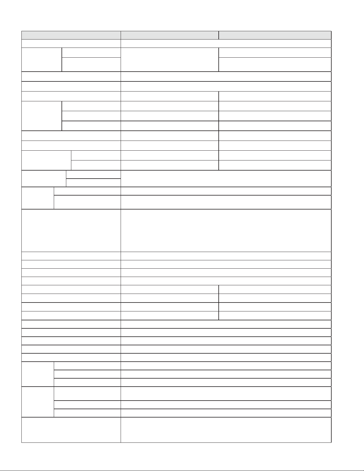
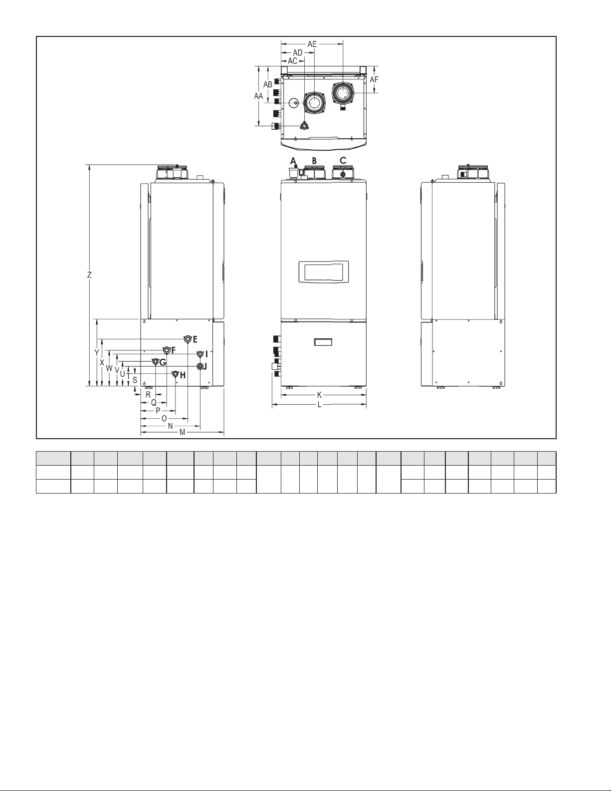
Figure 3 - Wall Mount Model Dimensions
Description Diameter
A Automatic Air Vent -
B Air Intake Adapter
3”
C Exhaust Vent Adapter
D Pressure Relief Valve Adapter 3/4” NPTF
E CH Supply Adapter
1” NPT
F CH Return Adapter
G DHW Outlet Adapter
3/4” NPTH DHW Inlet Adapter
I Gas Inlet Adapter
J Condensate Adapter 1/2” NPT (3/4” PVC Socket on Floor Models)
Table 9 - Adapter Specifications - All Models
Model K L M N O P Q R S T U V W X Y Z AA AB AC AD AE
140 17.3 34 15.4
10.6
6.7 4.3 2.8 5.1 11.0 2.3 5.7 8.9
10.8
14.9 15.1 10.5 5.9 2.3 6.8 12.6 3.9
199 19.7 37 16.8 7.8 5.4 4.0 6.3 12.3 2.5 5.9 10.6 16.6 17.0 12.5 7.0 3.2 9.2 15.1 3.7
How the Appliance Operates
Condensing technology intelligently delivers hydronic heating
while maximizing efficiency. Outlined below are the features of the
system and how they operate:
Stainless Steel Heat Exchanger - The highly efficient 316L stainless
steel fire tube heat exchanger with internal aluminum is designed
to extract all available heat from the combustion process and pass
it into heat transfer fluid. The stainless steel construction provides
protection for longer service life. The heat exchanger offers greater
water content, providing lower system pressure and greater overall
system efficiency.
10 to 1 Modulating Combustion System - The combustion
system is specially designed to provide very high turn down. This
combustion system will modulate the burner output to very low
levels to match the system demand and achieve better overall
control of the heating system for maximum efficiency and reliability.
Control – The integrated control system monitors the system and
responds to internal and external signals to regulate fan speed and
control output. This allows the appliance to deliver only the amount
of heat energy required and nothing more.
The control can be set up to monitor outdoor temperature through
an outdoor sensor to regulate appliance set point temperature,
increasing overall system efficiency while providing great comfort. The
system can be further enhanced by installing an indirect water heater
to provide domestic hot water.
The control can regulate the output of multiple appliances through its
cascade system function by establishing one appliance as the master
and the other connected appliances as followers. The master appliance
requires a sensor to provide feedback on set point temperature
in order to adjust heating output from the connected appliances.
Multiple appliance cascaded systems offer greater system turndown
and redundancy.
Electronic LCD Display – The high resolution display allows the user
to monitor appliance functions. The display also provides the means
to program the system parameters to maximize the efficiency of the
system design.
Combustion System (Blower – Gas Valve – Mixer – Burner – Spark
Ignition) – The highly efficient spark ignition combustion system uses
a variable speed blower to adjust combustion as the system requires
more or less energy. The negative regulated gas valve provides only
the amount of fuel required to ensure clean combustion. The mixer
accurately regulates the combination of gas and air throughout
Table 10 - Wall Mount Specifications and Dimensions
whl-648 Rev. 000 Rel. 003 Date 3.6.18
16
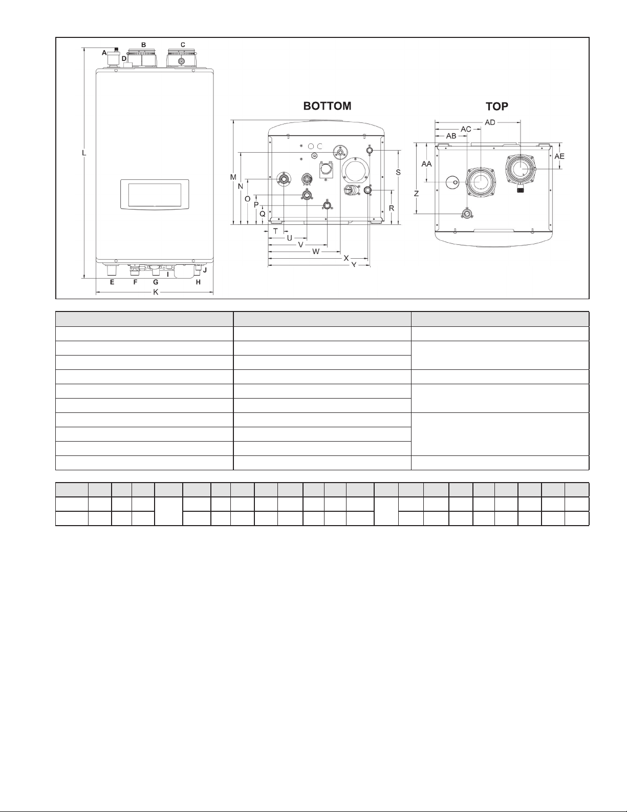
Figure 4 - Floor Model Dimensions
Table 11 - Floor Model Specifications and Dimensions
the modulating range to ensure high reliability. The burner is
constructed of durable ceramic metal fiber for long service life.
Appliance Sensors (Inlet – Outlet – Flue - Outdoor) - Sensors
provide highly accurate temperature monitoring to assure accurate
system control. These sensor inputs can be monitored through the
appliance control system and display.
Pressure Gauge – Allows the user to monitor system pressure.
System Safeties – The appliance is provided with many safety
features to ensure reliable and safe operation. Each safety is
connected to the appliance control. The appliance will alert the
user if an unsafe condition occurs and needs to be addressed. The
following are provided safeties: Flue Pressure Switch (monitors flue
pressure), Burner High Limit (monitors burner plate temperature),
High Limit Water Switch (monitors appliance temperature), Low
Water Sensor (monitors water level in the heat exchanger), optic
flame sensor (monitors flame quality), Flue Sensor (monitors flue
temperature), Condensate Pressure Switch (monitors pressure to
ensure condensation does not back up into appliance).
Manual Air Vent – Each appliance is equipped with an air vent to
discharge air from the system during start–up.
Intake and Exhaust Adapters – The appliance is equipped with
adapters to ease connection to the vent system. The adapters are
provided with clamps and seals to secure field supplied piping, and
test ports to ease monitoring of the combustion system. Each appliance
is supplied with a 6 inch piece of CPVC that must be connected into the
exhaust vent adapter.
Appliance 1” Return and 1” Supply Connection – Appliances are
equipped with both top and bottom piping connections for greater
installation flexibility.
Gas Connection – The appliance is equipped with a ¾” gas connection
to connect the incoming gas supply.
Field Wiring and Power Switch – Each appliance is supplied with a
power switch to cut off power. The appliance is also equipped with two
front mounted terminal strips. These terminal strips are separated into
low and line voltage to ease system wiring.
Condensate Trap and Hose Assembly – Each appliance has a built-
in condensate trap to control the discharge of condensate produced
by the appliance during normal operation. A corrugated condensate
hose is also provided to ensure proper drainage of condensate into
the pump or drain.
Low Water Cut Off Probe – LWCO is provided with each appliance
to ensure the appliance has an adequate water level to eliminate
overheating and damge to the heat exchanger.
Pump Service Mode – Allows manual operation of pumps to
commission system and check pump operation.
Model K L M N O P Q R S T U V W X Y Z AA AB AC AD AE AF
140 17.3 19.1 16.8 12 9.5 7 5.3 3
2.5 4 5 6.5 7.3 9.5 13.5
44.8 12 7.4 4.7 6.8 12.6 5.5
199 19.7 21.5 18.2 13.3 10.8 8.3 6.6 4.3 48 14 8.5 3.2 9.2 15.1 5.2
whl-648 Rev. 000 Rel. 003 Date 3.6.18
17
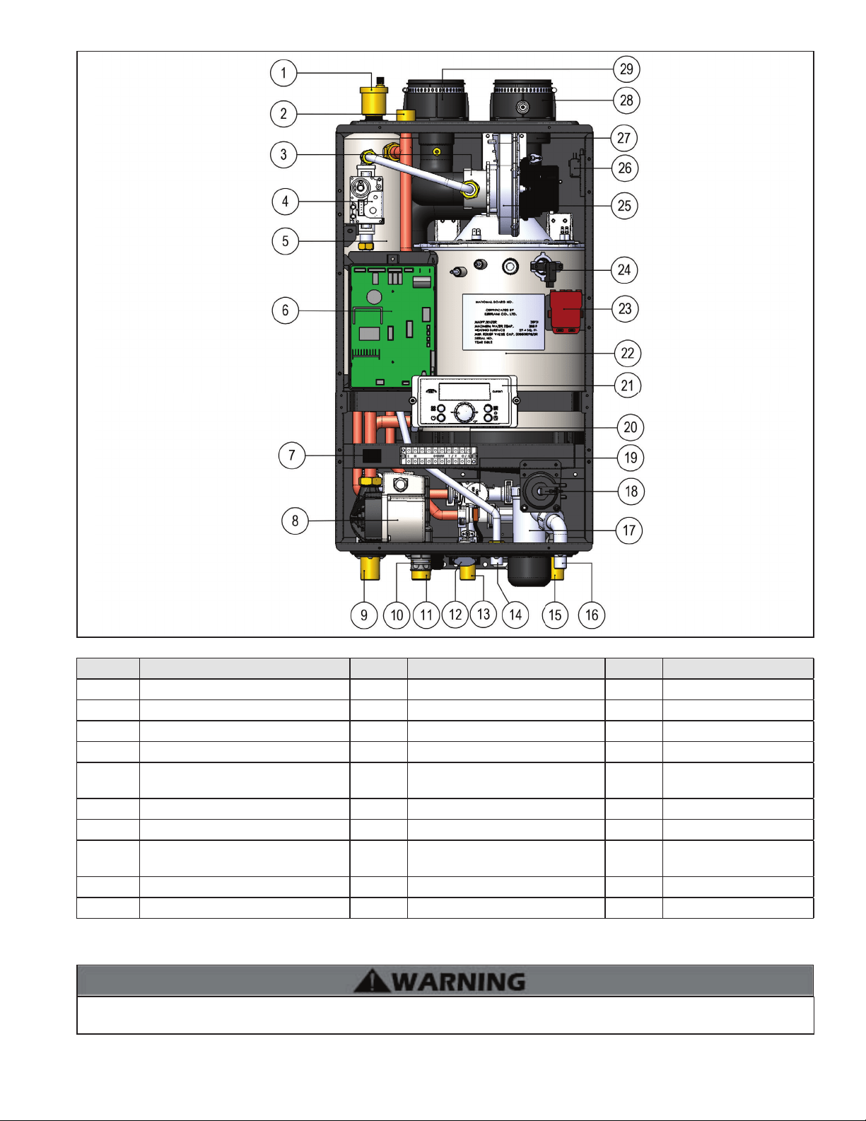
Figure 5 - Components
Number Component Description Number Component Description Number Component Description
1 Air Vent 11 CH Return Adapter 21 Control Panel
2 Relief Valve Adapter 12 CH Pressure Gauge 22 Heat Exchanger
3 Air / Gas Mixing Pipe 13 DHW Outlet Adapter 23 Ignition Transformer
4 Gas Valve 14 Gas Inlet Adapter 24 Flame Detecting Sensor
5 Internal Storage Tank 15
DHW Inlet Adapter with Filter and
Flow Restrictor
25 BLDC Fan
6 Main PCB 16 Condensate Adapter 26 Air Pressure Switch
7 Manual ON/OFF Power Switch 17 Condensate Trap 27 Exhaust Vent Pipe
8
Internal Recirculation Pump (DHW) /
CH Internal Primary Pump
18 Condensate Air Pressure Switch 28 Exhaust Vent Adapter
9 CH Supply Adapter 19 Mixing Valve 29 Air Intake Adapter
10 CH Return Filter 20 Terminal Block
Table 12 - Component List
J. Wall-Mounting (Wall Mount Models Only)
The appliance may be installed on any suitable internal wall (suitable sound-proofing may be required when installing onto a stud partition
wall).
The appliance must be installed on a wall that can bear its weight (more than 110 lbs. when fully plumbed and full of water). Installing the
appliance on a wall which cannot support its weight could result in property damage, personal injury, or death.
whl-648 Rev. 000 Rel. 003 Date 3.6.18
18
This appliance is too heavy for one person to lift. It is highly recommended to install the appliance with two people. Use caution as to not
drop the appliance, which could damage the appliance and cause property damage and/or severe personal injury. Verify that the appliance
is properly and securely mounted before leaving unsupervised. Failure to comply with the above and properly mount the appliance could
result in substantial property damage, severe personal injury, or death.
This wall mounting system is not seismic rated and should not be applied as such. Failure to comply with the above and properly mount the
appliance could result in substantial property damage, severe personal injury, or death.
Positioning the Appliance on the Wall
1. Attach the wall bracket on the location where you want to install the appliance. Ensure it is level and on stud (16” centers) before
proceeding.
2. Mark the four drill holes with a pencil or marker. Remove the wall bracket.
3. Drill four (4) holes using a 5/32 drill bit at the marked hole locations.
4. Mount the wall bracket to the wall with the four (4) included anchor bolts. Ensure the mounted bracket is level. See Figure 7A.
5. Align the appliance bracket grooves on the back of the appliance with the tongues on the wall bracket and hang the appliance on the
bracket. See Figure 7B.
Figure 6 - Wall-Mounting the Appliance
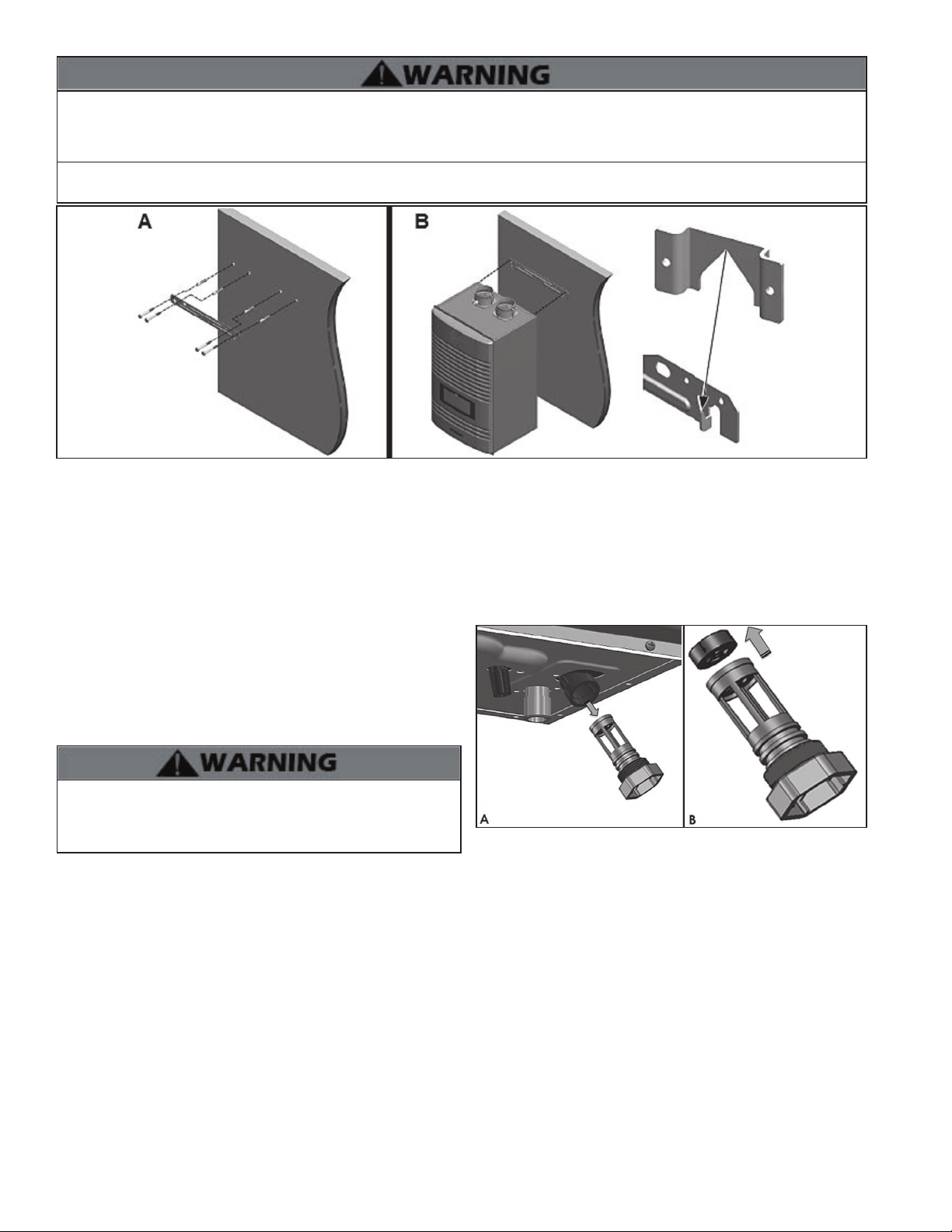
K. Flow Restrictor
A flow restrictor is installed on this appliance in the DHW inlet adapter
to avoid excessive flow at the faucets. See Flow Charts, this manual, for
more information.
If it is necessary to further increase flow to the system, replace the
factory installed white flow restrictor with the blue included with the
appliance by following the instructions below.
If the appliance is already fully installed, turn the gas, power, and
water off to the appliance and drain all water from the appliance
BEFORE proceeding. Failure to comply could result in substantial
property damage, severe personal injury, or death.
Figure 7 - A - Removing the DHW Inlet Filter, B - Removing the Flow
Restrictor
1. Locate the DHW inlet adapter on the bottom of the appliance.
2. Pull the two pins to release the DHW inlet filter. See Figure 7-A. The flow restrictor is attached to the top of the filter assembly.
3. Remove the installed white flow restrictor and replace it with the blue flow restrictor included with the appliance. See Figure 7-B.
4. Reinstall the DHW inlet filter.
5. Reinstall the two pins.
whl-648 Rev. 000 Rel. 003 Date 3.6.18
19
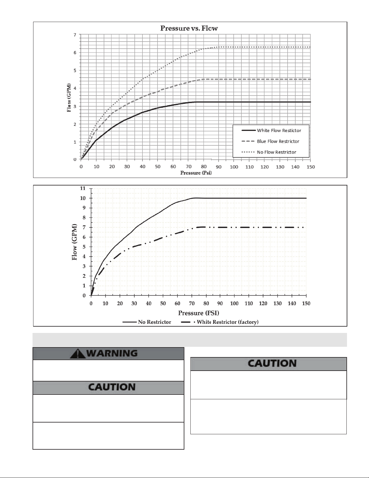
Figure 8 - Water Pressure vs. Flow through the Restrictors - 140 Models
Figure 9 - Water Pressure vs. Flow through the Restrictors - 199 Models
Part 4 - Water Piping
Failure to follow the instructions in this section WILL VOID the
warranty and may result in property damage, severe personal
injury, or death.
Do not apply a torch within 12” of the appliance. If sweat
connections are used, sweat tubing to the adapter before fitting
adapter to the water connections on the appliance. Damages due
to improper installation practices ARE NOT covered by warranty.
Dielectric unions or galvanized steel fittings must not be used in a
system with this appliance. Doing so WILL VOID the warranty. Use
only copper, brass, or stainless steel fittings. Teflon thread sealant
must be used on all connections.
A. General Plumbing Guidelines
Use two wrenches when tightening water piping at the appliance.
Use one wrench to prevent the appliance return or supply line from
turning. Failure to prevent piping connections from turning could
cause damage to appliance components.
The appliance control module uses temperature sensors to provide
both high limit protection and modulating temperature control. The
control module also provides low water protection by sensing the
water level in the heat exchanger. Some codes / jurisdictions may
require additional external controls.
The water connections must be installed in accordance with all local
and national plumbing codes, or any applicable standard which
prevails.
whl-648 Rev. 000 Rel. 003 Date 3.6.18
20
B. Backflow Preventer
It may be recommended to use a backflow preventer - check local
codes. If a backflow preventer or a no return valve is used, a thermal
expansion tank must be installed on the cold water supply between
the appliance and the valve.
C. Expansion Tank
Expansion Tank
1. Ensure that the expansion tank is designed and sized to correctly
handle system water volume and temperature. Check technical
specifications for the water content of this appliance.
Undersized expansion tanks cause system water to be lost from the
relief valve, causing make-up water to be added. Eventual appliance
failure can result due to excessive make-up water addition. SUCH
FAILURE IS NOT COVERED BY WARRANTY.
2. The expansion tank must be located as shown in Applications, this
manual, or following recognized design methods. See expansion tank
manufacturer’s instructions for details.
3. Connect the expansion tank to the air separator only if the air
separator is on the suction side of the circulator. Always install the
system fill connection at the same point as the expansion tank
connection to the system.
To control thermal expansion, a thermal expansion tank should be
installed in systems with an installed backflow preventer. DO NOT use
a closed type expansion tank. Follow expansion tank manufacturer’s
specifications to properly size an expansion tank to the installation.
Failure to properly accommodate thermal expansion could result in
property damage, severe personal injury, or death.
Expansion tanks must be sized according to total system volume.
This includes all length of pipe, all fixtures, appliances, etc. Failure to
properly accommodate thermal expansion could result in property
damage, severe personal injury, or death.
DO NOT install automatic air vents on closed type expansion tank
systems. Air must remain in the system and return to the tank to
provide an air cushion. An automatic air vent would cause air to leave
the system, resulting in improper operation of the expansion tank.
Diaphragm (or Bladder) Expansion Tank
Always install an automatic air vent on top of the air separator to
remove residual air from the system.
D. Piping the Appliance
Use both thread tape and pipe dope to connect the 3/4” DHW inlet
and outlet pipes. A shut off valve between the city water supply and
DHW inlet is recommended for ease of service. Westinghouse offers
threaded 3/4” DHW tankless isolation valves with a DHW pressure
relief valve for ease of installation and future service.
Use both thread tape and pipe dope to connect the 1” CH return and
supply pipes. Isolation valves between are recommended for ease
of service.
Use at least the MINIMUM pipe size for all appliance loop piping
This is to avoid the possibility of inadequate flow through the
appliance. Using less than the required minimum pipe size and
piping could result in system problems, property damage, and
premature appliance failure. Such problems ARE NOT covered by
product warranty.
tPipe material must be suitable to meet local codes and industry
standards.
tThe pipe must be cleaned and without blemish before any
connections are made.
tThe size of the DHW pipes should be 3/4” diameter, and the CH
pipes should be 1” diameter.
tIsolation (shutoff valves) should be used on both the CH and
DHW loops to ease future servicing.
tAll piping should be insulated.
It is recommended to install a sweat shut-off valve and a union in the
return and supply piping to ease future servicing. If there is a backflow
preventer or any type of a no return valve in the system, install an
additional tee here, suitable for an expansion tank.
