Hydro Smart 199 Condensing Gas Micro Boiler
Installation Manual and Owner’s Guide
If the information in these instructions is
not followed exactly, a re or explosion
may result causing property damage,
personal injury or death.
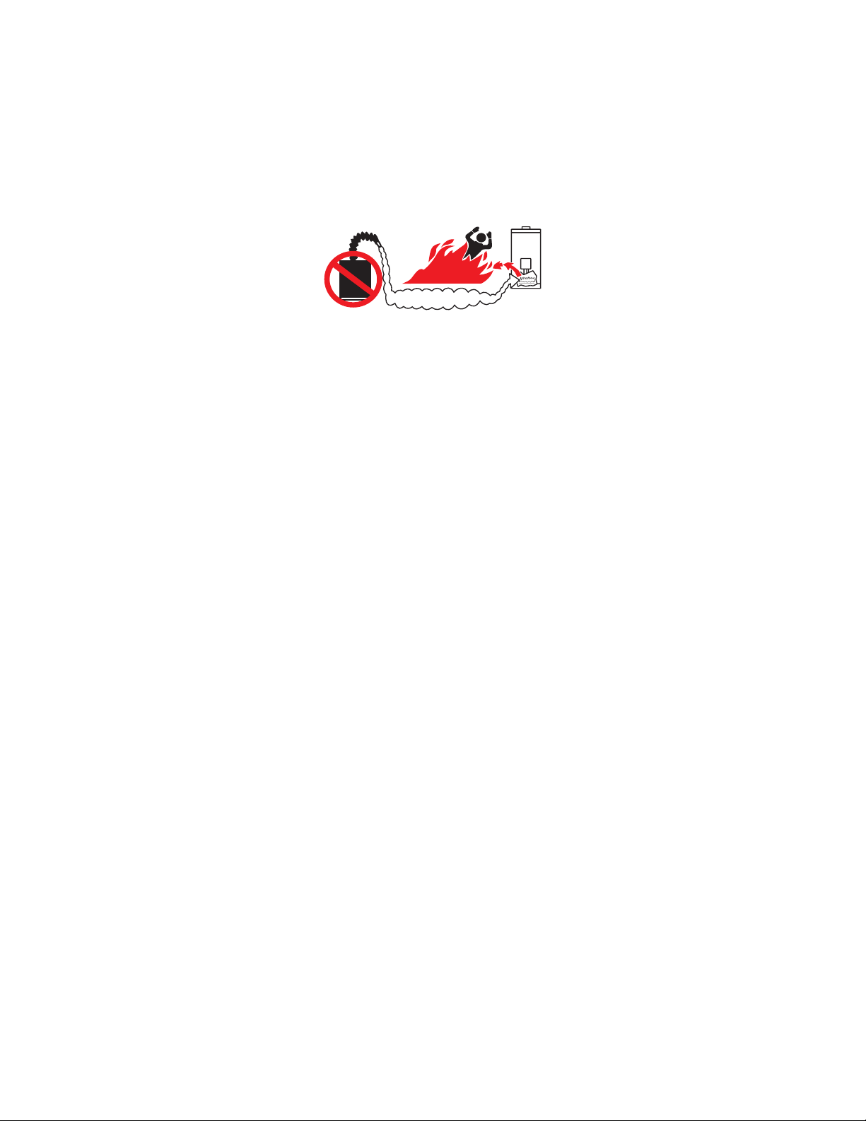
-Do not store or use gasoline or other ammable
vapors and liquids in the vicinity of this or any
other appliance.
-WHAT TO DO IF YOU SMELL GAS
• Do not try to light any appliance
• Do not touch any electric switch, do not use
any phone in your building.
• Immediately call your gas supplier from a
neighbor’s phone. Follow the gas supplier’s
instructions.
• If you cannot reach your gas supplier, call the
re department.
-Installation and service must be performed by
a qualied installer, service agency or the gas
supplier.
If you have any questions,
please call or write to:
10725 165th Ave. NW
Elk River, MN 55331
Models:
HS199Con-NG
HS199Con-LP
Featuring
• Efciency: 95 %
• Wall Hung
• Flow Activated: .5 GPM
• Copper Heat Exchanger
• Temperature Range: 80°-160° F*
• Freeze Protection
• Power Vent
• PVC Venting
*Up to 185 with optional control
The Hydro Smart 199 Condensing
Gas Micro Boiler is a compact and
powerful residential unit with a versatile
BTU modulating range.
Do not return to stores. Damages or
repairs call Hydro Smart 763-331-3066
M-F 8 AM - 5 PM Sat 8 AM - Noon

2
CONTENTS
Installation Manual
SPECIFICATIONS..........................................................................................................4
INTRODUCTIONS..........................................................................................................5
SAFETY GUIDELINES...................................................................................................6
INSTALLATION...............................................................................................................7
General................................................................................................................7
Clearances...........................................................................................................9
Included accessories............................................................................................9
High-altitude installations....................................................................................10
Venting instructions.............................................................................................11
Gas supply and gas pipe sizing..........................................................................21
Water connections..............................................................................................23
Condensate drain...............................................................................................25
Electrical connections.........................................................................................26
APPLICATIONS..................................................................................................27
INITIAL OPERATION..........................................................................................29
OWNER’S GUIDE
OPERATING SAFETY...................................................................................................31
NORMAL OPERATION.................................................................................................33
Temperature controller and Remote controller...................................................33
General..............................................................................................................33
Temperature Settings.........................................................................................34
Temperate table of controller..............................................................................34
Additional features..............................................................................................35
Temperature setting on the PCB (without remote controller).............................36
Flow....................................................................................................................37
Freeze protection system...................................................................................37
Maintenance and service...................................................................................38
Unit draining and lter cleaning..........................................................................38
TROUBLESHOOTING..................................................................................................39
General...............................................................................................................39
Error codes.........................................................................................................41
COMPONENTS DIAGRAM...........................................................................................44
PARTS LIST...................................................................................................................48
OUTPUT TEMPERATURE CHART...............................................................................50

3
Installation Manual
CONGRATULATIONS
Congratulations and thank you for choosing our condensing micro boiler.
Before use, we recommend that you read through this installation manual
carefully. Keep this manual for future reference.
If you need an additional manual, contact the manufacturer or your local
distributor. When you call, please tell us the product name and the serial
number of your unit written on the rating plate of the boiler.
4
SPECIFICATIONS
*18-25 PSI is recommended for maximum ow (Space Heating)
**The Manifold Pressure is the factory setting and generally should not need adjustment.
NOTE:
• Check the rating plate to ensure this product matches your specications.
• The manufacture reserves the right to discontinue, or change at any time, specications, or
designs without notice and without incurring obligation.
*When using boiler in-conjunction with Hydro Smart Combi panel, system pressure may be much higher on your domestic
water side. Your space heating side should still reect the recommended 18-25 PSI for system pressure.
Hydro Smart 199 Gas Condensing Micro-Boiler
BTU/h
Natural Gas Input
(Opera
Range)
000,51 :.niM
Max.: 199,000
BTU/h
Propane Input
(Opera
Range)
Gas
000,31 :.niM
Max.: 199,000
3/4" NPT
Water
3/4" NPT
psi
(MPa)
Water Pressure* 15 - 150 (0.1 - 1)
(kPa)
inch W.C.
Natural gas
Inlet Pressure
Min. 5.0 (1.24)
Max. 10.5 (2.61)
Propane
Inlet Pressure
inch W.C.
(kPa)
Manifold
Min. 8.0 (1.99)
Max. 14.0 (3.48)
Pressure**
Gas
Natural
inch W.C. 2.95
(Pa) (734)
Propane
3.3
(Pa)
inch W.C.
(821)
Weight lbs. (kg) 59 (26.8)
Dimensions
inch
mm
Electric
Electric
Supply
H 22.4 x W 17.7 x D 10.7
H 570 x W 450 x D 272
VAC/Hz 120 / 60
Consu
mp
Opera W / A 89.0 / 0.74
Standby W / A 4.2 / 0.04
Freeze-
Prot
W / A 175 / 1.5
5
INTRODUCTION
• This manual provides information necessary for the installation, operation, and maintenance of the
boiler.
• The model description is listed on the rating plate which is attached to the side panel of the boiler.
• Please read all instructions completely before installing this product.
• If you have any problems or questions regarding this equipment, consult the manufacturer or its
local representative.
• This equipment is a condensing micro boiler designed to efciently supply endless hot water for
your needs. (Radiant Heating, or Domestic Water used in-conjunction with Radiant Heating) See
Combi panel for more information on integrating domestic water with your radiant heating system.
• These high efciency models have a built-in secondary heat exchanger that absorbs latent heat
from the exhaust gas.
• These boilers are only to be installed indoors.
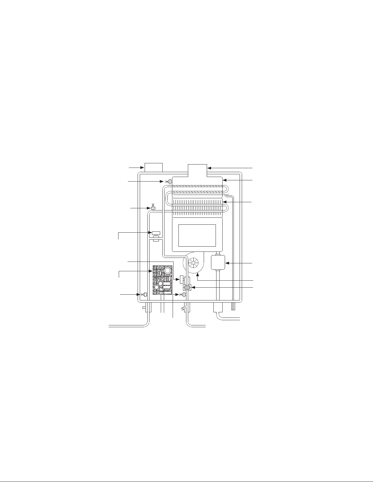
• The principle behind condensing micro boilers is easy:
*This diagram illustrates condensing micro boiler design concepts only and does not accurately repre-
sent the boilers physical description.
1. Your thermostat indicates a need for heat and turns on the circulator pump(s).
2. Water ows through the boiler.
3. The ow sensor detects the water ow.
4. The computer initiates the fan motor and sends a signal to the igniter to create an ignition spark.
5. The gas ignites and ames appear within the burner chamber.
6. Water circulates through the heat exchanger and then gets hot.
7. Using thermistors to measure temperatures throughout the micro-boiler, the computer modulates
the gas and water valves to ensure proper output water temperature.
8. When your room reaches desired temperature the pumps turn off and the boiler shuts down.
Exhaust
Secondary
heat exchanger
Condensate
drain port
Gas
Cold water inlet
Hot water outlet
Fan motor
Gas valves
Computer board
Thermistor
Thermistor
Bypass valve
Primary
heat exchanger
Intake port
Exhaust thermistor
Thermistor
Water control valve
Flow sensor
Burners
6
SAFETY GUIDELINES
SAFETY DEFINITION
GENERAL
Indicates an imminently hazardous situation which, if not avoided, will result in
death or serious injury.
Indicates an imminently hazardous situation which, if not avoided, could result in
death or serious injury.
Indicates an imminently hazardous situation which, if not avoided, could result in
minor or moderate injury.
1. Follow all local codes , or in the absence of local codes, follow the current edition of the National
Fuel Gas Code: ANSI Z223.1/NFPA 54 in the USA or B149.1 Natural Gas, Propane Installation
Code in Canada.
2. Properly ground the unit in accordance with all local codes or in the absence of local codes, with
the National Electrical Codes: ANSI/NFPA 70 in the USA or CSA standard C22.1 Canadian Electri-
cal Code Part 1 in Canada.
3. Carefully plan where you intend to install the micro boiler. Please ensure:
•Your micro boiler will have enough combustible air and proper ventilation
•Locate your micro boiler where water leakage will not damage surrounding areas.
4. Check the rating plate for the correct Gas Type, Gas Pressure, Water Pressure and Electric
Rating.
5. *If this unit does not match your requirements, do not install and consult with the manufacture.
6. If any problem should occur, turn off the unit and unplug the zone controls for the space heating
and/or combi panel system zone controls and turn off the gas. Then call a trained technician or the
Gas Company or the manufacture.
• Water temperature over 125°F (52°C) can cause severe burns instantly or
death from scalding. The water temperature is set at 120°F (50°C) from the
factory to minimize any scalding risk. If using micro boiler with Hydro Smart
Combi Panel, always check the water temperature. Always verify emitter wa-
ter delivery temperature requirements to avoid damage.
• Do not store or use gasoline or other ammables, vapors, or liquids in the
vicinity of this appliance.
• Do not reverse the uid and/or gas connections as this will damage the gas
valves and can cause sever injury or death.
• Do not use this appliance if any part has been in contact with or been im-
mersed in water. Immediately call a licensed plumber, a licensed gas tter, or
a professional service technician to inspect and/or service the unit if neces-
sary.
• Do not disconnect the electrical supply if the ambient temperature will drop
below freezing. The freeze protection system only works if the unit has electri-
cal power. The warranty will not be covered if the heat exchanger is damaged
due to freezing.
DANGER
WARNING
CAUTION
WARNING

7
INSTALLATION
GENERAL
1. Follow all local codes, or in the absence of local codes, follow the current edition of the National
Fuel Gas Code: ANSI Z223.1/NFPA 54 in the USA or B149.1 Natural Gas, Propane Installation
Code in Canada.
2. All gas micro boilers require careful and correct installation to ensure safe and efcient operation.
This manual must be followed exactly. Read the “Safety Guidelines” section.
3. The manifold gas pressure is preset at the factory. It is computer controlled and should not need
adjustment.
4. Maintain proper space for servicing. Install the unit so that it can be connected or removed easily.
Refer to the “Clearances” section for proper clearance.
5. The micro boiler must be installed in a location where the proper amount of combustible air will be
available to it at all times without obstructions.
6. The electrical connections requires a means of disconnections, to terminate power to the micro
boiler for servicing and safety purposes.
7. Do not install the unit where the exhaust vent is pointing into any opening in the building or where
the noise may disturb your neighbors. Make sure the vent termination meets the required distance
by local code from any doorway or opening to prevent exhaust from entering a building.
8. Particles from our, aerosols, and other contaminants may clog the air vent, build up and reduce
the functions of the rotating fan, cause improper burning of the gas, or cause damage to the micro
boiler. Regularly ensure that the area around the unit is dust or debris free. Regular maintenance
is recommended for these types of environment.
9. The Hydro Smart 199 condensing gas boiler is to be installed indoors only. This unit is equipped
with thermistors and a hi-limit switch for the exhaust gas, detecting excess temperatures within
the ue and enabling the unit to safely stop operations. These components are always monitoring
exhaust gas conditions in order to prevent heat damage to ABS, PVC, CPVC, or polypropylene
(Plastic) venting if ABS, PVC, CPVC, or polypropylene is used. If the exhaust gas temperatures
exceeds 140° F, these components will enable the unit to safely stop operations.
• The micro-boiler requires 3” or 4” make-up intake air supply pipe. The intake pipe must be sealed
airtight.
• Air supply pipe can be made of ABS. PVC (solid core), CPVC (solid core), polypropylene, corru-
gated stainless steel, or Category III/IV stainless steel. Regarding exhaust pipe refer to the “Ex-
haust section” under venting instructions.
• Sidewall venting is recommend for this boiler. Vertical venting (roof termination) is acceptable.
• The manufacturer recommends running the exhaust vent and the intake pipe as parallel as possi-
ble.
8
• Installation and service must be performed by a qualied installer (for
example, a licensed plumber or gas tter, otherwise the warranty will be
void.
• The installer (licensed professional) is responsible for the correct instal-
lation for the micro boiler and for compliance with all national, state /
provincial, and local codes.
• The manufacturer does not recommend installing the micro boiler in a
pit or location where gas and water can accumulate.
• Do not have the vent terminal pointing toward any operating window, door, or
opening into a building.
• Do not install next to any source of airborne debris, such as clothes dryer, that
can cause debris to be trapped inside the combustion chamber, unless the
system is direct vented.
• The manufacturer does not recommend installing the micro boiler in an
attic due to safety issues. If you install the micro boiler in an attic:
-Make sure the unit will have enough combustion air and proper ventilation.
-Keep the area around the micro boiler clean. When dust collects on the
ame sensor, the micro boiler will shut down on an error code.
-Place the unit for easy access for service and maintenance.
-A drain pan, or other means of protection against water damage, is to be
installed under the micro boiler in case of leaks.
• The warranty will not cover damage cause by water quality.
-Only distilled water or distilled water/glycol mixtures can be used with this
micro boiler, unless when used in-conjunction with Hydro-Smart Combi panel
system. Do not introduce pool or spa water, or any chemically treated water into
the micro boiler.
-Water hardness levels must not exceed 7 grains per gallon (120 ppm) for
single family applications or more than 4 grains per gallon (70 ppm) for all other
types of applications/ Water hardness leads to scale formation and may affect
/ damage the micro boiler. Hard water scaling must be avoided or controlled by
proper water treatment.
-Water pH levels must be between 6.5 and 8.5.
-Well water must be treated.
• Do no install the micro boiler where water, debris, or ammable vapors may
get into the ue terminal.
• Although the micro boiler is designed to operate with minimal sound, the
manufacturer does not recommend installing the unit on a wall adjacent
to a bedroom, or a room that is intended for quiet study or meditation,
etc.
• Locate your boiler close to a drain where water leakage will not do damage to
surrounding areas. As with any water heating appliance, the potential for leak-
age at some time in the life of the product does exist. The manufacturer will
not be responsible for any water damage that may occur. If you install a drain
pan under the unit, ensure that it will not restrict the combustion air ow.
WARNING
CAUTION
9
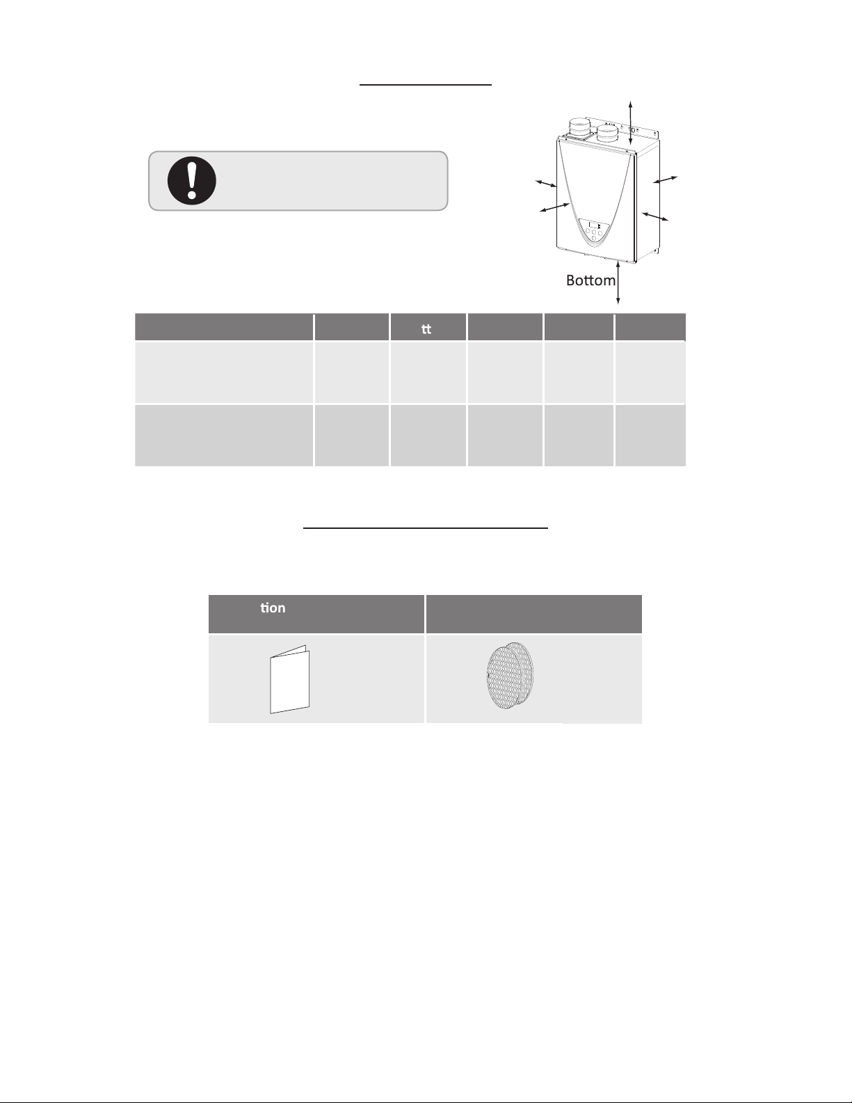
CLEARANCES
INCLUDED ACCESSORIES
Check that these items below are included with the micro boiler.
Maintain all clearances around
the micro-boiler.
Model Top Bo om Front Back Sides
HS199Con-NG
(Natural Gas)
12 in.
(914 mm)
12 in.
(305 mm)
24 in.
(610 mm)
0.5 in.
(13 mm)
2 in.
(51 mm)
*24 inches recommended for maintenance.
Back
Side
Side
Front
Top
12 in.
HS199Con-LP
(Liquid propane)
(914 mm)
12 in.
(305 mm)
24 in.
(610 mm)
0.5 in.
(13 mm)
2 in.
(51 mm)
Installa manual and owner’s
guide
Bird screen
1 :ytQ
Qty: 2
10
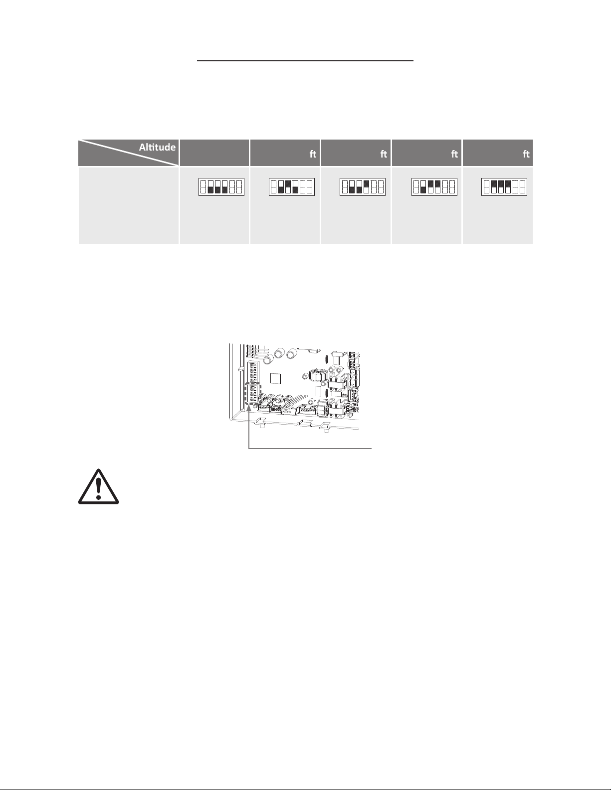
HIGH-ALTITUDE INSTALLATIONS
Check the elevation where your micro boiler is installed. Set DIPswitches shown in the table
below depending on the altitude.
NOTE: The dark squares indicate the direction the DIPswitches should be set to.
DO NOT adjust any DIPswitches on the upper bank.
0 (DEFAULT) Up to 2,500 Up to 5,000 Up to 7,500
HS199Con Boiler
Up to 10,100
(Lower bank of
DIPswitches)
No. 2 : OFF
No. 3 : OFF
No. 4 : OFF
No. 2 : OFF
No. 3 : ON
No. 4 : OFF
No. 2 : OFF
No. 3 : OFF
No. 4 : ON
No. 2 : OFF
No. 3 : ON
No. 4 : ON
No. 2 : ON
No. 3 : ON
No. 4 : ON
OFF
ON
1 2 3 4 5 6
OFF
ON
1 2 3 4 5 6
OFF
ON
1 2 3 4 5 6
OFF
ON
1 2 3 4 5 6
DIPswitches
OFF
ON
1 2 3 4 5 6
WARNING
Computer board
Lower bank of DIPswitches
11
VENTING INSTRUCTIONS
GENERAL
• Improper venting of this appliance can result in excessive levels of carbon
monoxide which can result in severe personal injury or death.
• Improper installation can cause nausea or asphyxiation, severe injury or death
from carbon monoxide and ue gases poisoning. Improper installation will
void product warranty.
When installing the vent system, all applicable national and local codes must be
followed. If you install thimbles, re stops or other protective devices and they
penetrate any combustible or noncombustible construction, be sure to follow all
applicable national and local codes.
This appliance must be vented in accordance with the section” Venting of Equipment” of the current
edition of the National Fuel Gas Code: ANSI Z223.1/NFPA 54 in the United States and/or Section 8 of
the B149.1 Natural Gas and Propane Installation Code in Canada, as well as applicable local building
codes. The use of venting materials approved for Category III/IV appliances is recommended when-
ever possible. However, this appliance may also be vented with plastic pipe materials such as ABS,
PVC (solid core), CPVC (solid core), or polypropylene. For details, please refer toe the Exhaust
Vent (ABS, PVC, CPVC, or Polypropylene Vent) Section. Vent installations in Canada which utilize
plastic vent systems must use venting that complies with ULC S636.
General rules for venting micro boilers are:
General rules for vent terminations:
• Place the micro boiler as close as possible to the vent termination.
• The vent collar of the micro boiler must be fastened directly to an unobstructed vent pipe.
• Do not weld the vent pipe to the micro boiler’s vent collar.
• Do not cut the vent collar of the unit.
• The vent must be easily removable from the top of the boiler for normal service and inspection of
the unit.
• The micro boiler vent must not be connected to any other gas appliance or vent stack except an
approved common venting system.
• Avoid using an oversized vent pope or using extremely long runs of the pope unless it is part of an
approved common vent system.
• For rooftop venting, a rain cap or other from of termination that prevents rain water from entering
into the micro boiler must be installed.
• Do not terminate vent into chimney. If the vent must go through the chimney, the vent must run all
the way through the chimney with approved vent pipe.
• Avoid locating the micro boiler vent termination near any air intake devices. These fans can pick
up the exhaust ue products from the micro boiler and return them to the building. This can create
a health hazard.
• Locate the vent termination so that it cannot be blocked by any debris, at any time. Most codes re-
quire that the termination be at least 12 in. (305 mm) above grade, but the installer may determine
if it should be higher depending on the job site condition and applicable codes.
• A proper sidewall termination is recommended when the micro boiler is vented through a sidewall.
• Be sure to check the clearance form the exhaust termination to the air inlet or opening in the vent
termination clearances section.
DANGER
CAUTION
12
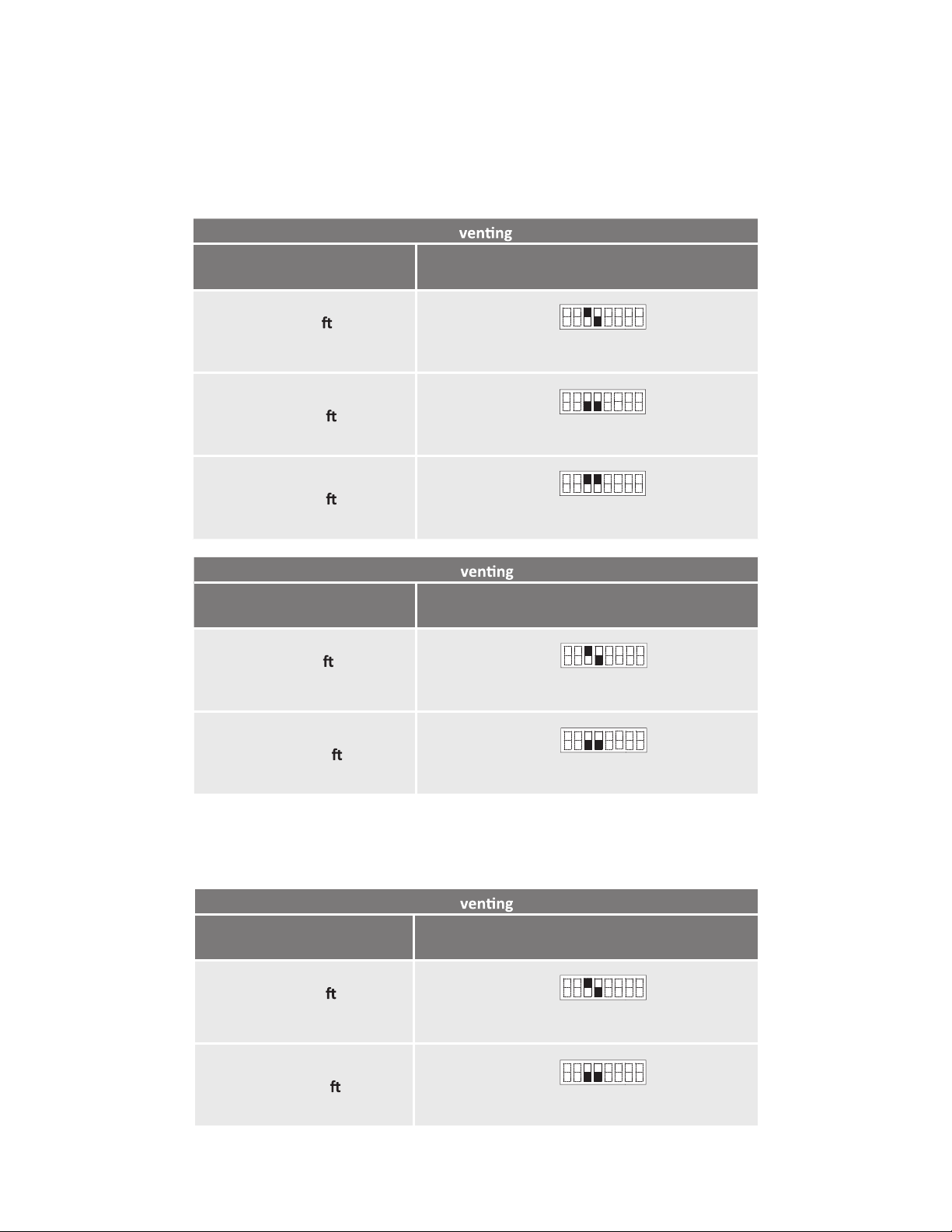
DIPswitch settings for Vent length
<Two-pipe, direct-vent installation>
Set DIPswitches shown in the tables below depending on vent length.
<Single pipe with room-air intake installation>
Set DIPswitches shown in the tables below depending on vent length.
4"
Vent length
(Upper bank of DIPswitches)
5 to 50
(DEFAULT)
No. 3 : ON
No. 4 : OFF
51 to 100
No. 3 : OFF
No. 4 : OFF
ON
1 2 3 4 5 6 7 8
OFF
ON
1 2 3 4 5 6 7 8
OFF
3"
Vent length
(Upper bank of DIPswitches)
5 to 20
(DEFAULT)
No. 3 : ON
No. 4 : OFF
21 to 40
No. 3 : OFF
No. 4 : OFF
41 to 70
No. 3 : ON
No. 4 : ON
ON
1 2 3 4 5 6 7 8
OFF
ON
1 2 3 4 5 6 7 8
OFF
ON
1 2 3 4 5 6 7 8
OFF
3"
Vent length
(Upper bank of DIPswitches)
5 to 45
(DEFAULT)
No. 3 : ON
No. 4 : OFF
46 to 70
No. 3 : OFF
No. 4 : OFF
ON
1 2 3 4 5 6 7 8
OFF
ON
1 2 3 4 5 6 7 8
OFF
13
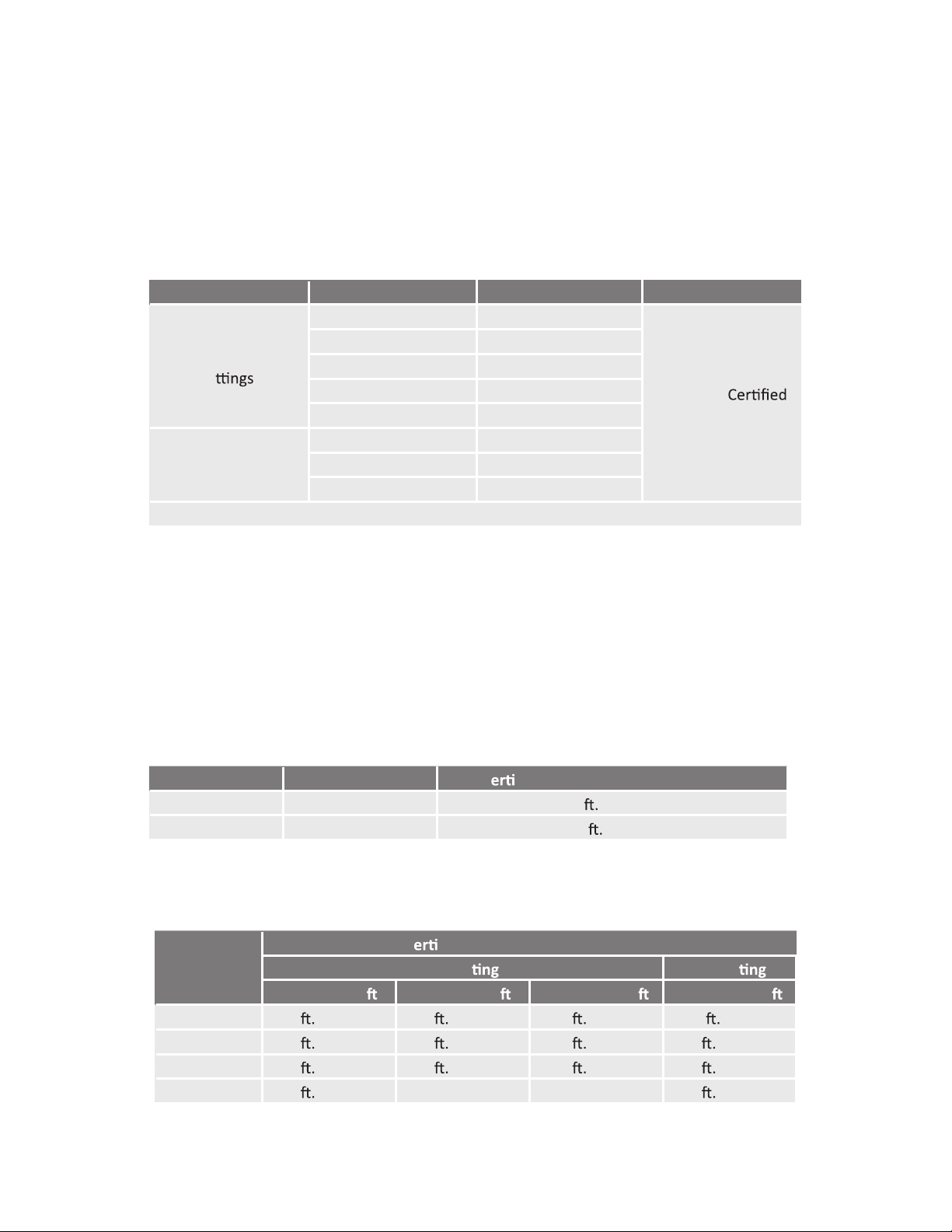
Exhaust vent (ABS, PVC, CPVC, or polypropylene vent)
This appliance can be vented with ABS, PVC, CPVC, or polypropylene (temperature rated up to
149°F). Vent material certied to ULC S636 standards is recommended in the USA. In Canada, plas-
tic venting must be certied to ULC S636 standards.
• The maximum length of exhaust vent piping must not exceed 70 ft. (21.3 m) for 3” venting, which
depends on the elevation where the micro boiler is installed, and 100 ft (30.5 m) for 4” venting (de-
ducting 5 ft. (1.5 m) for each elbow used in the venting system). Do not use more than 5 elbows.
See the table below.
• When the horizontal vent run exceeds 5 ft. (1.5 m), support the vent run at 3 ft. 0.9 m) intervals
with overhead hangers.
*For each elbow added, deduct 5 ft. (1.5 m) from max vent length.
Excludes vent terminators, termination elbows, or rain caps.
Item Material CanadaUnited States
Exhaust pipe and
Fi
Schedule 40 PVC ANSI/ASTM D1785
PVC-DWV
ULC S636
Materials Only
ANSI/ASTM D2665
Schedule 40 CPVC ANSI/ASTM F441
Schedule 40 ABS-DWV ANSI/ASTM D2661
UL-1738Polypropylene
Pipe Cement/Primer
PVC ANSI/ASTM D2564
CPVC
ABS
ANSI/ASTM F493
ANSI/ASTM D2235
NOTE: Do NOT Use Cellular Foam Core Pipe
Diameter Max. No. of Elbows
53 in. (76 mm) 70
(21.3 m)
5
Max. V
cal and Horizontal (Total) Vent Length
4 in. (102 mm) 100
(30.5 m)
No. of Elbows 3" ven 4" ven
Up to 3,000
Max. V cal or Horizontal (Total) Vent Length
Up to 6,000
Up to 10,100
0
Up to 10,100
70 (21.3 m) 40 (12.2 m) 25 (7.6 m)
1
100 (30.5 m)
65
(19.8 m) 35 (10.7 m) 20 (6.1 m)
2
95 (29.0 m)
60
(18.3 m) 30 (19.1 m) 15 (4.6 m)
5
90 (27.4 m)
N/A45
(13.7 m) N/A 75 (22.9 m)
14
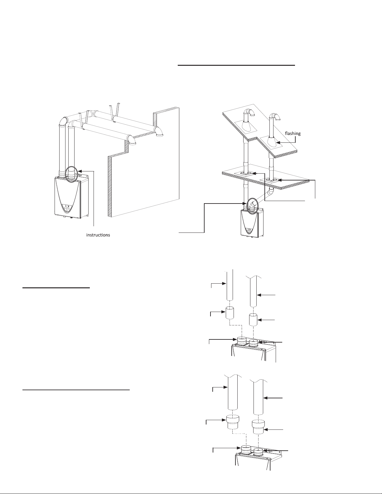
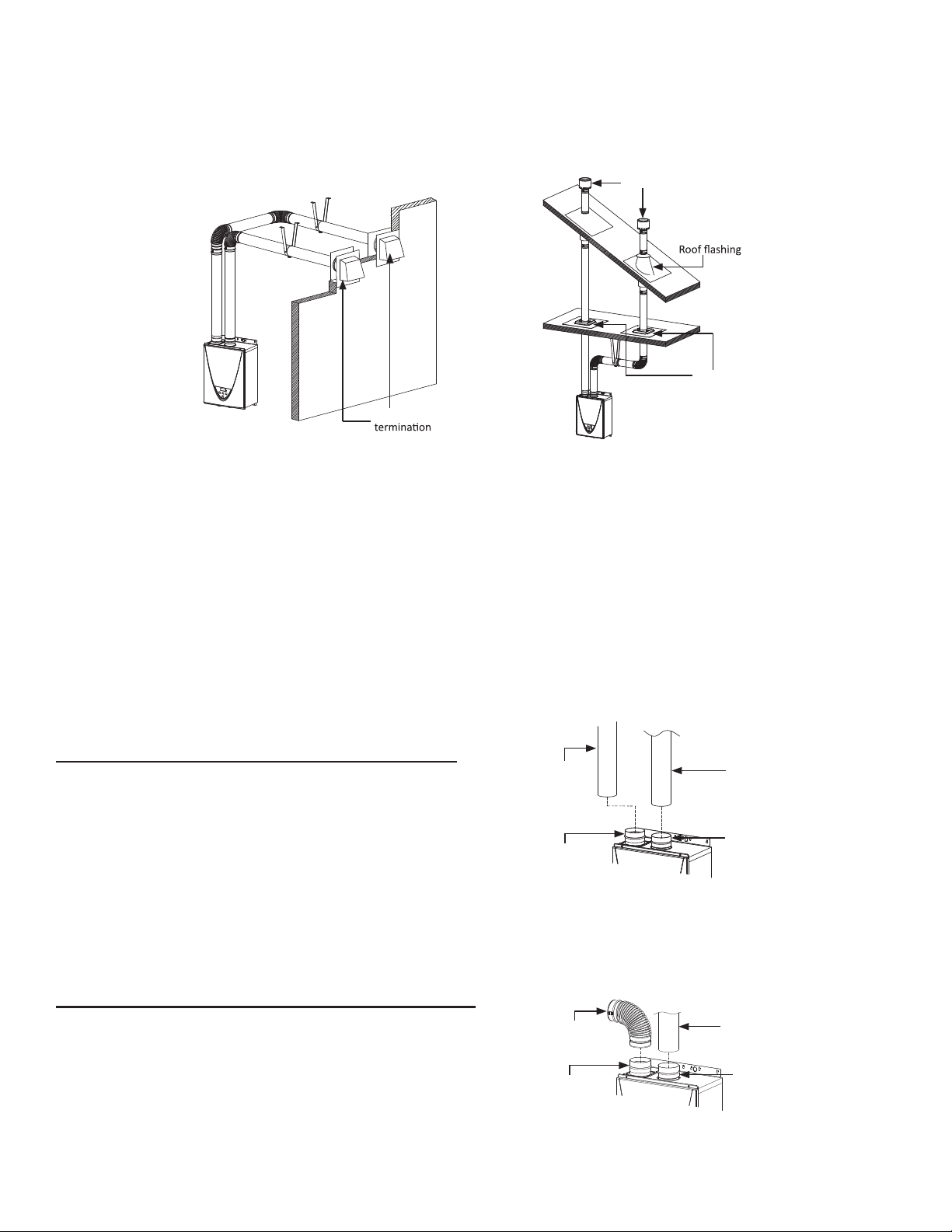
Two-pipe, direct vent illustrations
Typical installation using PVC. ABS, or polypropylene vent
Horizontal Installation Vertical Installation
For details of the optional items, refer to the installation manual for each optional item.
<How to install intake and exhaust venting (two-pipe, direct vent)
3” vent connection
1. Connect 3” couplings directly on
the exhaust and intake vent collar
of the micro boiler.
2. Connect 3” straight pipes to the
couplings.
From 3” to 4” vent connection
1. Connect 3” x 4” increasers directly
on the exhaust and intake vent
collar of the micro boiler
2. Connect 4” straight pipes to the
increasers.
Roof
Roof
Fire stop
Wall
Connect between exhaust vent collar and piping.
See the below.
3” coupling
Exhaust vent collar
(Female)
3” straight pipe
3” coupling
Intake vent collar
(Female)
3” straight pipe
4” straight pipe
3"x4" increaser
Exhaust vent collar
(Female)
4” straight pipe
Intake vent collar
(Female)
3"x4" increaser
15
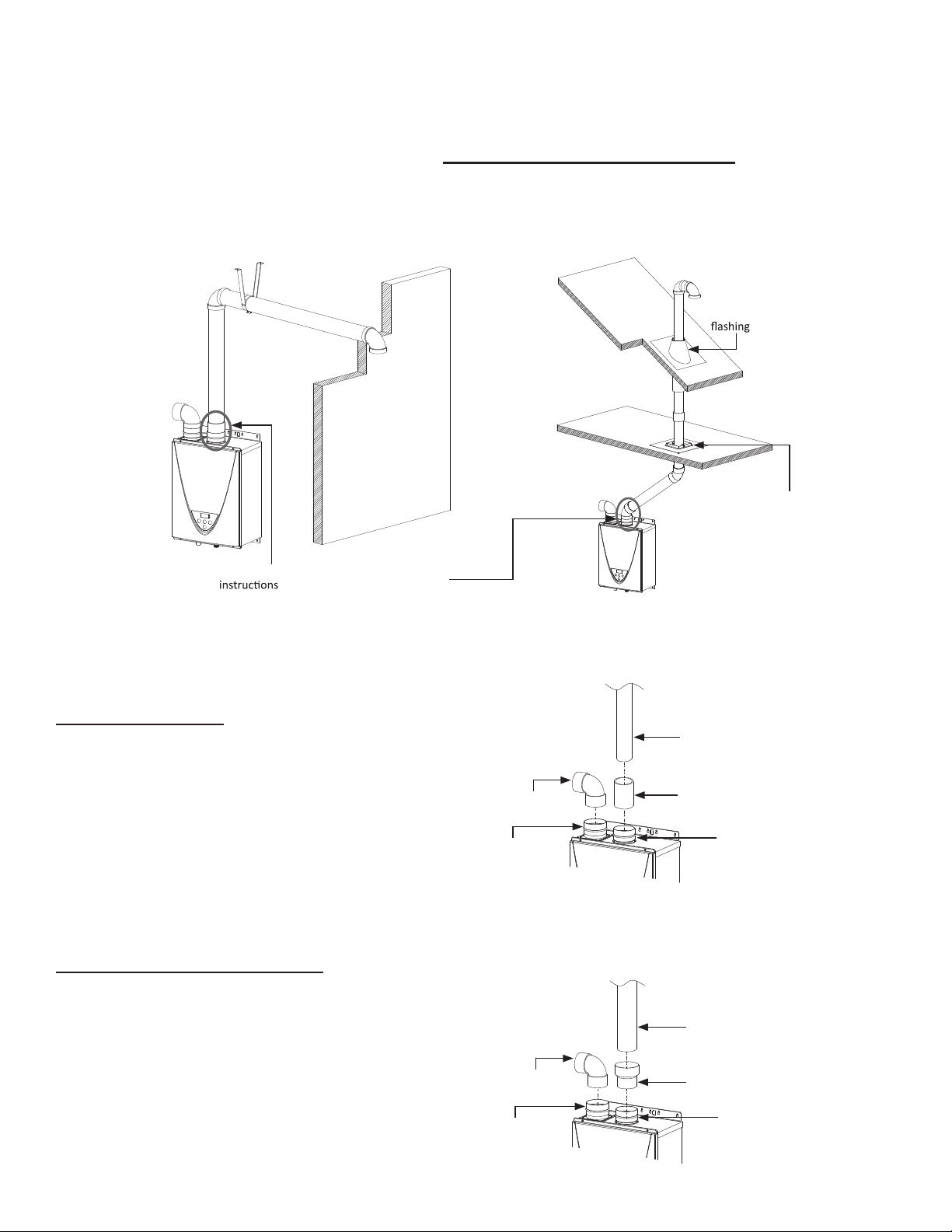
Single pipe with room-air intake illustrations
Typical installation using PVC. ABS, or polypropylene vent
Horizontal Installation Vertical Installation
For details of the optional items, refer to the installation manual for each optional item.
<How to install single vent>
3” vent connection
1. Connect 3” elbow directly on the
intake vent collar of the micro boiler.
2. Connect a 3” coupling directly on
the exhaust vent collar of the micro
boiler.
3. Connect a 3” straight pipe to the
coupling.
From 3” to 4” vent connection
1. Connect 3” elbow directly on the
intake vent collar of the micro boiler.
2. Connect 3” x 4” increasers directly
on the exhaust vent collar of the
micro boiler
3. Connect a 4” straight pipe to the
increasers.
Roof
Fire stop
Connect between exhaust vent collar and piping.
See the below.
Roof
Elbow
Elbow
Wall
3” coupling
3” straight pipe
3” elbow with
Exhaust vent collar
(Female)
bird screen
Intake vent collar
(Female)
4” straight pipe
3"x4" increaser
Exhaust vent collar
(Female)
3” elbow with
bird screen
Intake vent collar
(Female)
16
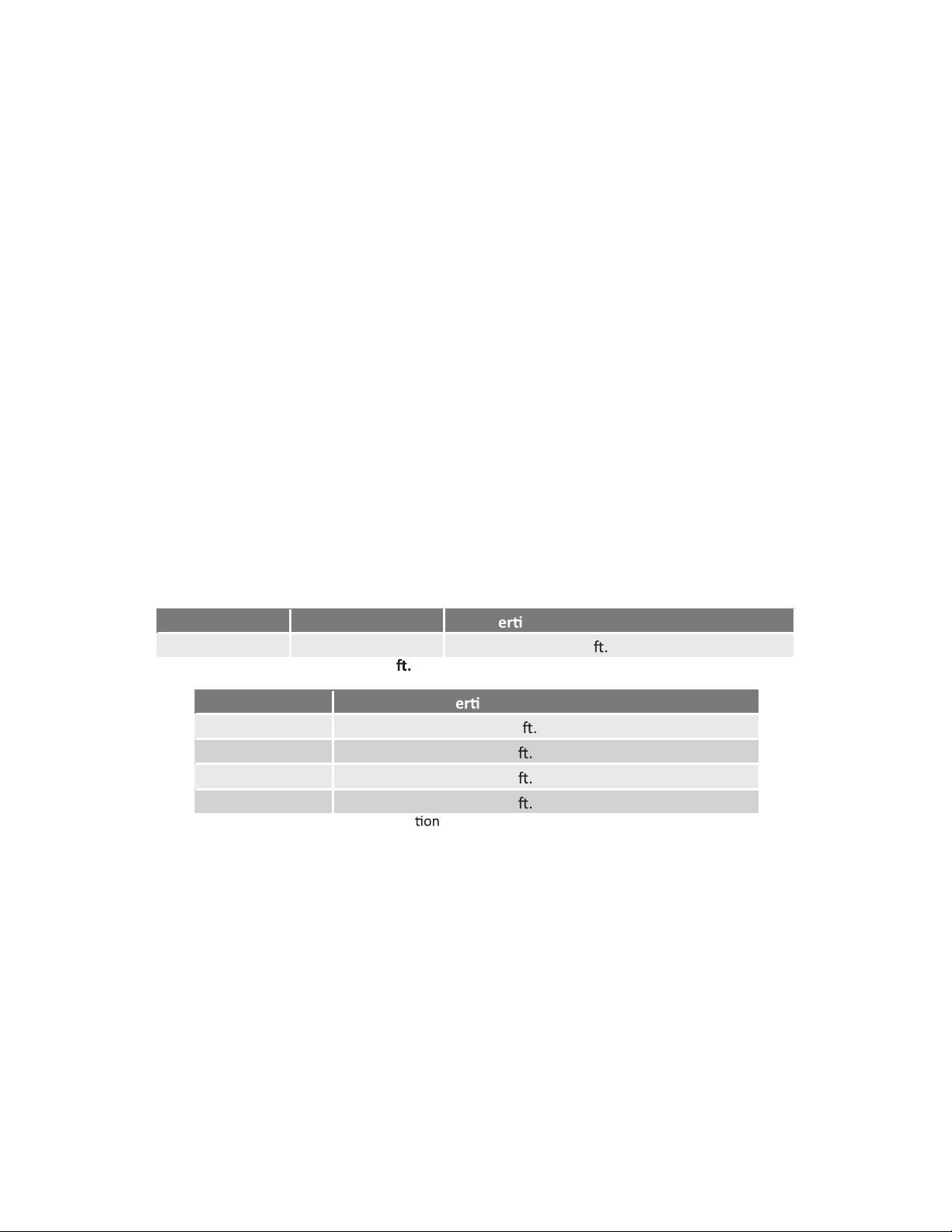
Exhaust vent (Stainless Steel Vent)
This is a Category IV appliance and must be vented accordingly. The vent system must be sealed
airtight. All seams and joints without gaskets must be sealed with high heat resistant silicone sealant
or UL listed aluminum adhesive tape having a minimum temperature rating of 160° F. For best results,
a vent system should be as short and straight as possible.
• The micro boiler is a Category IV appliance and must be vented accordingly with any 4” vent ap-
proved for use with Category III/IV or Special BH type gas vent.
• The manufacturer recommends the NovaVent line. However, the following are also UL listed man-
ufactures: ProTech Systems Inc.(FasNSeal), Metal-Fab Inc., and Heat-Fab Inc. (Saf-T-Vent).
• Follow the vent pipe manufacturer’s instructions when installing the vent pipe.
• The maximum length of exhaust vent piping must not exceed 100 ft. (30.5 m) (deducting 5 ft (1.5
m) for each elbow used in the venting system). Do not use more than 5 elbows.
• When the horizontal vent run exceeds 5 ft. (1.5 m), support the vent run at 3 ft. (0.9 m) intervals
with overhead hangers.
Diameter Max. No. of Elbows
54 in. (102 mm)
Max. V cal and Horizontal (Total) Vent Length
100
(30.5 m )
*For each elbow added, deduct 5 (1.5 m) from max. vent length.
No. of Elbows
0
1
100
(30.5 m)
Max. V
cal or Horizontal Vent Length
2
95
(29.0 m)
5
90 (27.4 m)
75
(22.9 m)
Excludes vent terminators, termina elbows, or rain caps.
17
Direct-vent and single vent illustrations
Horizontal Installation Vertical Installation
• The diagram above shows direct-vent installations. For single vent installation, connect a 4” elbow
directly on the intake vent collar instead of a straight pipe. See the instructions below for the detail.
• For details of the optional items, refer to the installation manual for each optional item.
• Regarding the clearances from the exhaust terminal to the air inlet or opening, refer to next few
pages.
• Follow all vent system manufacturer’s instructions and all local codes.
• Use 4” Category III/IV approved or Special BH, single or double wall stainless steel vent pipe.
<How to install single vent>
4” vent connection for direct vent installation
1. Connect 4” stainless steel vent
straight pipes directly on the ex-
haust/intake vent collar of the micro
boiler.
4” vent connection for a single vent installation
1. Connect 4” stainless steel vent
straight pipes directly on the exhaust
vent collar of the micro boiler.
2. Connect a 4” elbow directly on the
intake vent collar of the micro boiler.
Roof
Fire stop
Rain cap
Wall
Sidewall vent
Hanger
Hanger
Intake vent
collar (Female)
4" (102 mm)
stainless steel vent
straight pipe
Exhaust vent collar
of the Indoor
models (Female)
4" (102 mm)
stainless
steel vent
straight pipe
Exhaust vent collar
of the Indoor models
(Female)
4” (102 mm)
stainless steel vent
straight pipe
Intake vent
collar (Female)
4" (102 mm)elbow
with bird screen
18
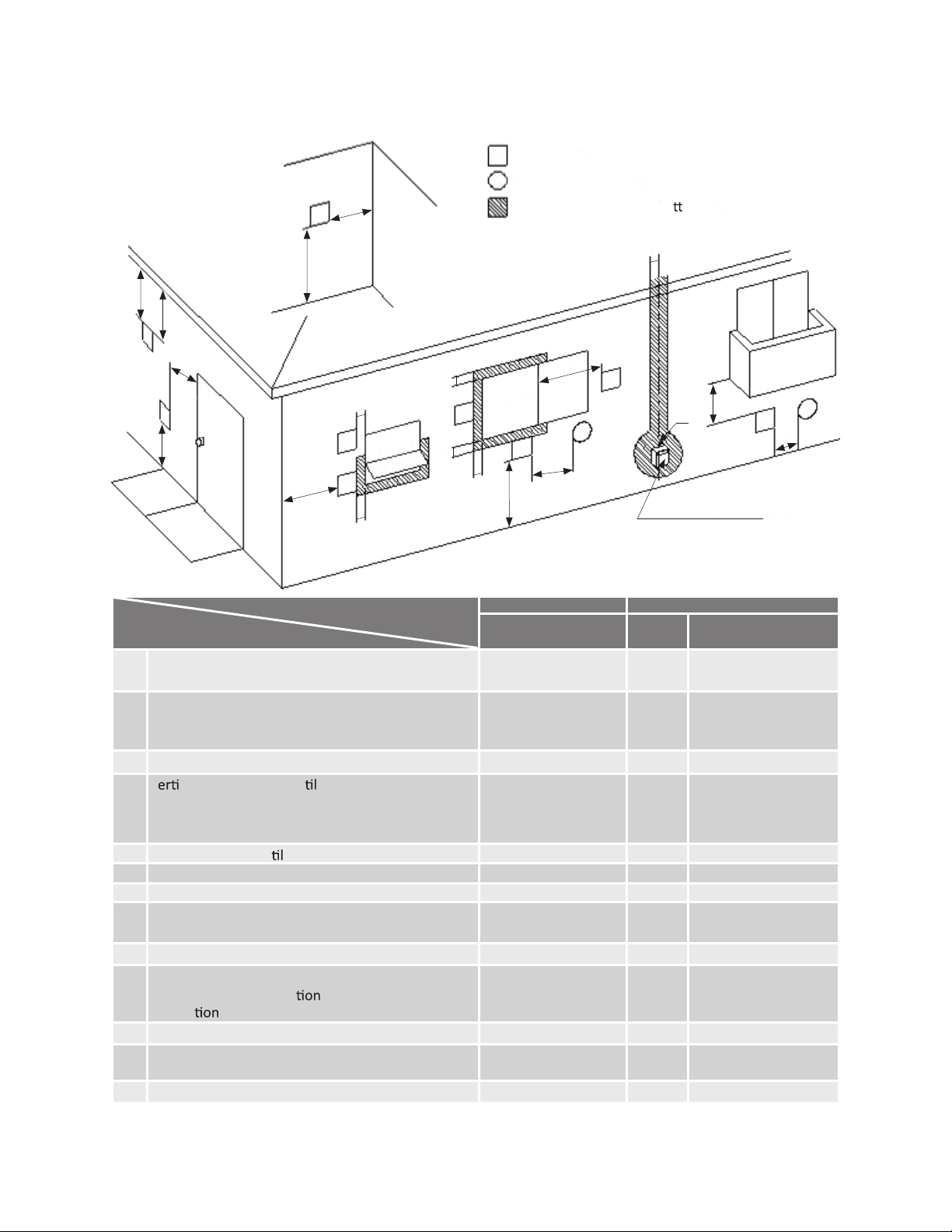
Vent termination clearances
*For clearances not specied in ANSI Z223.1/NFPZ 54 (US) or B149.1 (Canada), please use clear-
ances in accordance with local installation codes and the requirements of the gas supplier.
Canada U.S.A
Direct-
vent
Other than Direct-vent and other
than Direct-vent Direct-vent
balcony
1 foot 1 foot 1 footA
Clearance above grade, veranda, porch, deck, or
3 feet 1 foot B Clearance to window or door that may be opened
* * *
D
4 feet from below or
side opening. 1 foot
from above opening
C Clearance to permanently closed window
* * *
* * *E Clearance to unven
ated soffit
* * *F Clearance to outside corner
* * *G Clearance to inside corner
V
cal clearance to ven ated soffit located above
the vent terminator within a horizontal distance
of 2 feet (61cm) from the center line of the
terminator
* *3 feetH
Clearance to each side of center
line extended
above meter/regulator assembly
* *
J
3 feetI Clearance to service regulator vent outlet
3 feet 1 foot
Clearance to non-mechanical air supply inlet to
building or the combus
air inlet to any other
applica
6 feet
4 feet from below or
side opening. 1 foot
from above opening
3 feetK Clearance to mechanical air supply inlet 3 feet
*7 feetL
Clearance above paved sidewalk or paved driveway
located on public property
7 feet
*1 foot *M Clearance under veranda, porch deck, or balcony
V
INSIDE CORNER DETAIL
V
V
V
V
V
V
V
V
V
Gas meter / regulator
X
X
X
G
A
E
D
B
L
C
F
B
Vent terminal
Air supply inlet
Area where is not permi
ed
B
B
B
A
J
OPERABLE
CL
B
FIXED
OSED
H
M
K
OPERAB E
CL D
L
I
FIXED
OSE
19
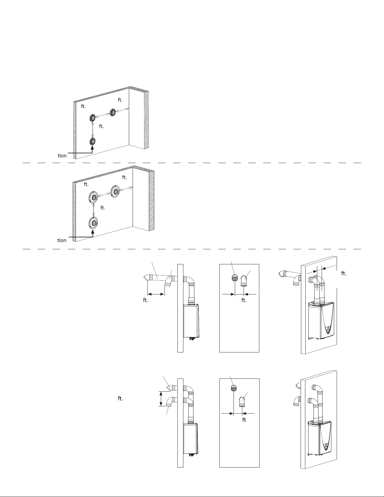
For sidewall terminations
Please follow all local and national codes in regards to proper termination clear-
ances. In the absence of such codes, the clearances below can be used as
guidelines. Local codes supersede these guidelines.
For multiple sidewall exhaust terminations (e.g. Multi-unit
Systems), an exhaust termination must be at least 1 ft.
(305mm) away from another exhaust termination. An ex-
haust termination must also be at least 2 ft. (610mm) away
from an inside corner. (If the adjacent wall is less than 2 ft.
(610mm) of length, the minimum required distance away
from the inside corner will be equal to the length of that
adjacent wall.)
For multiple-unit, direct-vent sidewall terminations that
combine the intake and exhaust into a single penetration,
space each direct-vent termination at least 1 ft. (305mm)
away from each other, no matter the orientation. A direct
vent termination must also be at least 2 ft. (610mm) away
from an inside corner. (If the adjacent wall is less than 2 ft.
(610mm) of length, the minimum required distance away
from the inside corner will be equal to the length of that
adjacent wall.)
For direct-vent sidewall
terminations that use
two separate pene-
trations for the intake
and exhaust, keep the
termination clearances
shown in the diagrams
on the right.
<Case 1>
<Case 2>
Exhaust
termina
Inside
corner
1
(305 mm) min
min
2
1 (305 mm)
(610 mm) min
Combined
intake and
exhaust
Inside
termina
corner
1
(305 mm) min
2
min
1 (305 mm)
(610 mm) min
1 (305 mm) min
0.5
(159 mm) min
Exhaust
Intake
Exhaust
Intake
min
0.5
1 (305 mm)
(159 mm) min
0.5
min
(159 mm)
Exhaust
Intake
Exhaust
Intake
20
3 (914 mm) min
Exhaust gas
Intake air
1
(305 mm) min
1
(305 mm) min
2 (610 mm) min
1
(305 mm) min
1
(305 mm) min
Intake air
Exhaust
gas
1
(305 mm) min
Exhaust
termina
min
2 (610 mm)
Exhaust and/or direct-vent sidewall terminations should be
at least 2 ft. (610mm) away from an opposite surface/wall.
Do not place the termination directly in front of an opening
into a building.
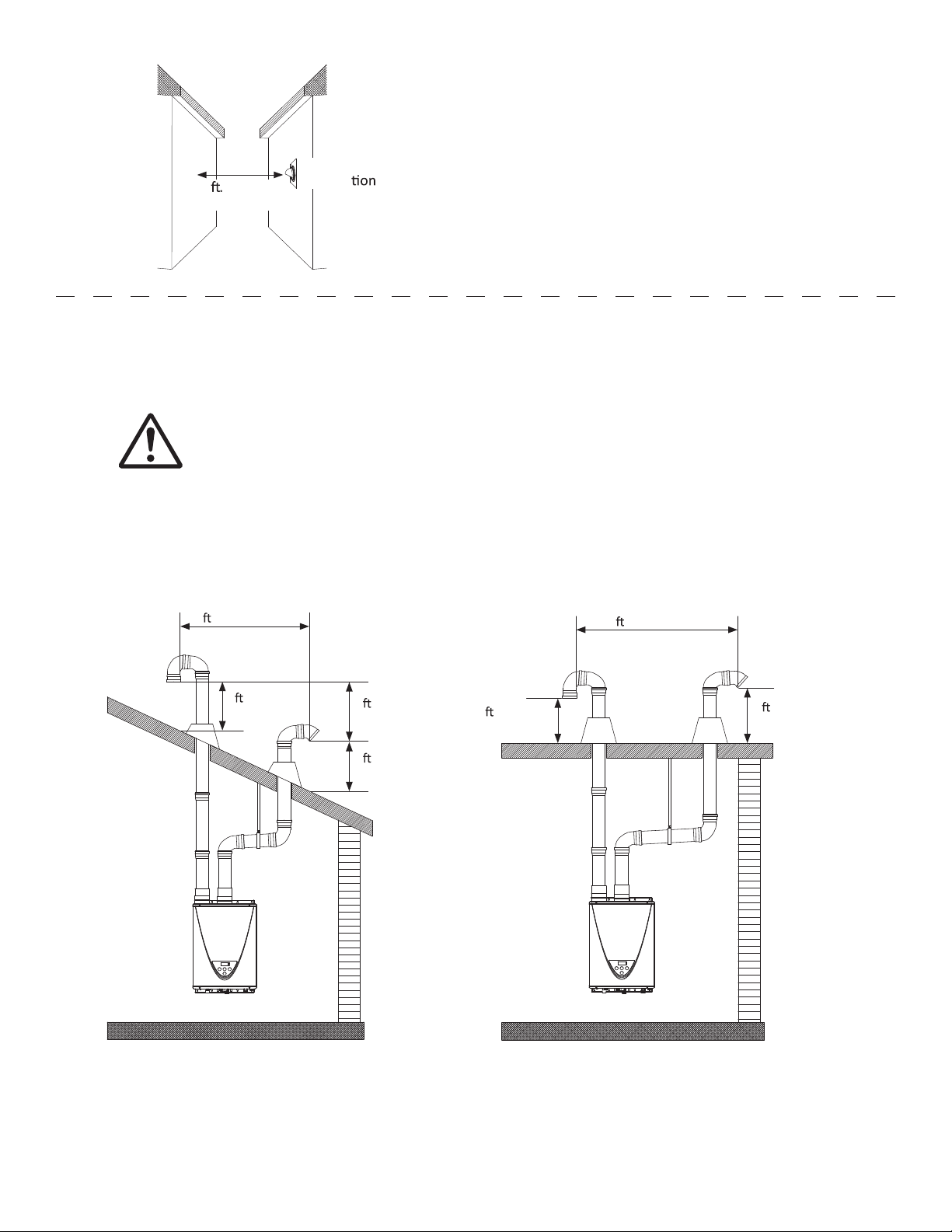
For rooftop terminations
Please follow all local and national codes in regards to proper termination clear-
ances. In the absence of such codes, the clearances below can be used as
guidelines. Local codes supersede these guidelines.
Exhaust terminations must be at least 1 ft. (305 mm) away from any obstructions.
CAUTION
21
GAS SUPPLY AND GAS PIPING SIZE
• Check that the type of gas matches the rating plate rst.
• Ensure that any and all gas regulators are operating properly and
providing gas pressures withing the specied range shown below.
Excess gas inlet pressure may cause serious accidents.
• Conversion of this unit from natural gas to propane or vice versa will void all
warranty. Contact your local distributor to get the correct unit for your gas
type. The manufacturer is not liable for nay property and/or personal
damage resulting from gas conversions.
• The minimum and maximum inlet gas pressures are:
• Inlet gas pressures that fall outside the range of values listed above may adversely affect the per-
formance of the micro boiler. These pressures are measured when the micro boiler is in full opera-
tion.
• Inlet gas pressure must not exceed the above maximum values; gas pressure above the specied
range will cause dangerous operating conditions a damages to the unit.
• Until testing of the main gas line supply pressure is completed, ensure the gas line to the micro
boiler is disconnected to avoid any further damage.
Gas connections
1. Install a manual gas shutoff valve between the micro boiler and the gas supply.
2. When the gas connections are completed, it is necessary to perform a gas leak test either by
applying soapy water to all gas ttings and observing for bubble or by using a gas leak detection
device.
• The micro boiler and its individual shutoff valve must be disconnected from the gas supply pip-
ing system during any pressure testing of that system at the test pressures in excess of 1/2 psi
(3.5kPa).
• The micro boiler must be isolated from the gas supply piping system by closing its individual
manual shutoff valve during any pressure testing of the gas supply piping system at test pressures
equal to or less than 1/2 psi (3.5 kPa).
3. Always purge the gas line of any debris and/or water before connecting to the gas inlet.
Size the gas pipe appropriately to supply the necessary volume of gas required for
the micro boiler using ANSI Z223.1/NFPA 54 in the USA of B149.1 in Canada or
local codes. Otherwise, ow capabilities and output temperatures will be limited.
CAUTION
Gas type Inlet gas pressure
Natural Gas
Propane
Min. 5.0” W.C. (1.24 kPa) – Max. 10.5” W.C. (2.61 kPa)
Min. 8.0” W.C. (1.99 kPa) – Max. 14.0” W.C. (3.48 kPa)
NOTICE
22
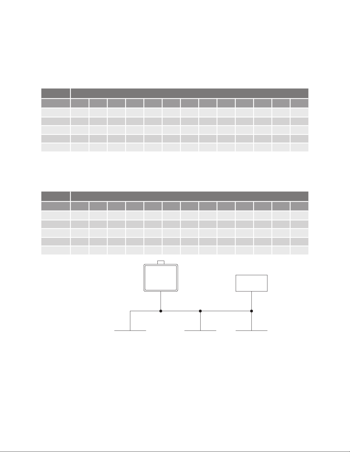
Natural Gas Supply Piping
Maximum delivery Capacity of Cubic Feet of Gas per Hour of IPS Pipe carrying Natural Gas with 0.60
Specic Gravity Based on Pressure Drop of 0.5”W.C.
Based on Energy Content of 1,000 BTU/Cubic ft.: The micro boiler requires 199 Cubic ft./hr.
Propane (LP) Supply Piping
Maximum Capacity of Propane (LP) Based on 11” W.C. supply pressure at 0.5” W.C. pressure drop.
Based on Energy Content of 1,000 BTU/Cubic ft.
Divide each appliance’s BTU/h requirement by 1,000 BTU/ft³ to get the appliances ft³/h requirement.
Take into account the distance the appliance is from the gas meter, look in the above gas chart to properly size the line.
For sections of the gas line supplying gas to more than one appliance (Ex. Point A to Point B), add up the cubic ft. per
hour requirements of the appliances that are being supplied by that section, and size to the farthest appliance.
For Example: The section from A to B supplies gas to the furnace, range and dryer. Adding up the BTU/h requirements
and dividing by 1,000 yields a cubic ft. per hour requirements of 220 cubic ft. of gas per hour. The farthest appliance is the
range, which is 50 ft. away form the meter. Looking at the above chart, and under column of 50 ft., Section A to B needs to
be 1” in order to supply 220 cubic ft.
Pipe Size Length
10' 20'Diameter 30' 40' 50' 60' 70' 80' 90' 100' 125' 150' 200'
3/4"
363 249 200
1" 684 470 377 323 286 259 239 222 208
1
1/4"
1,404 965 775 663 588 532 490 456 428 404 358 324 278
1
1/2"
2,103 1,445 1,161 993 880 798 734 683 641 605 536 486 416
2" 4,050 2,784 2,235 1,913 1,696 1,536 1,413 1,315 1,234 1,165 1,033 936 801
Unit: Cubic feet per hour
Micro-
boiler
Dryer
199,000 BTU/h
35,000 BTU/h
Furnace
Gas meter
Range
120,000 BTU/h
A
B
65,000 BTU/h
C
10' Length
1/2" Pipe size
15' Length
1/2" Pipe size
15' Length
1" Pipe size
10' Length
3/4" Pipe size
10' Length
5' Length
1" Pipe size
1-1/4" Pipe size
10' Length
3/4" Pipe size
5' Length
1-1/4" Pipe size
Unit: kBTU per hour
elpmaxe gnizis saG
(Natural Gas)
LengthPipe Size
10'Diameter 20' 30' 40' 50' 60' 70' 80' 90' 100' 125' 150' 200'
3/4"
567 393 315 267 237 217
1" 1,071 732 590 504 448 409 378 346 322 307 275 252 213
2,2051
1/4"
1,496 1,212 1,039 913 834 771 724 677 630 567 511 440
1
1/2"
3,307 2,299 1,858 1,559 1,417 1,275 1,181 1,086 1,023 976 866 787 675
2" 6,221 4,331 3,465 2,992 2,646 2,394 2,205 2,047 1,921 1,811 1,606 1,496 1,260
23
Measuring inlet gas pressure
1. Turn off all electric power to the micro boiler if service is to be performed.
2. Turn the manual gas valve located on the outside of the unit clockwise to
the off position.
3. Failure to follow these steps could lead to a re or explosion, resulting in
personal injury or death.
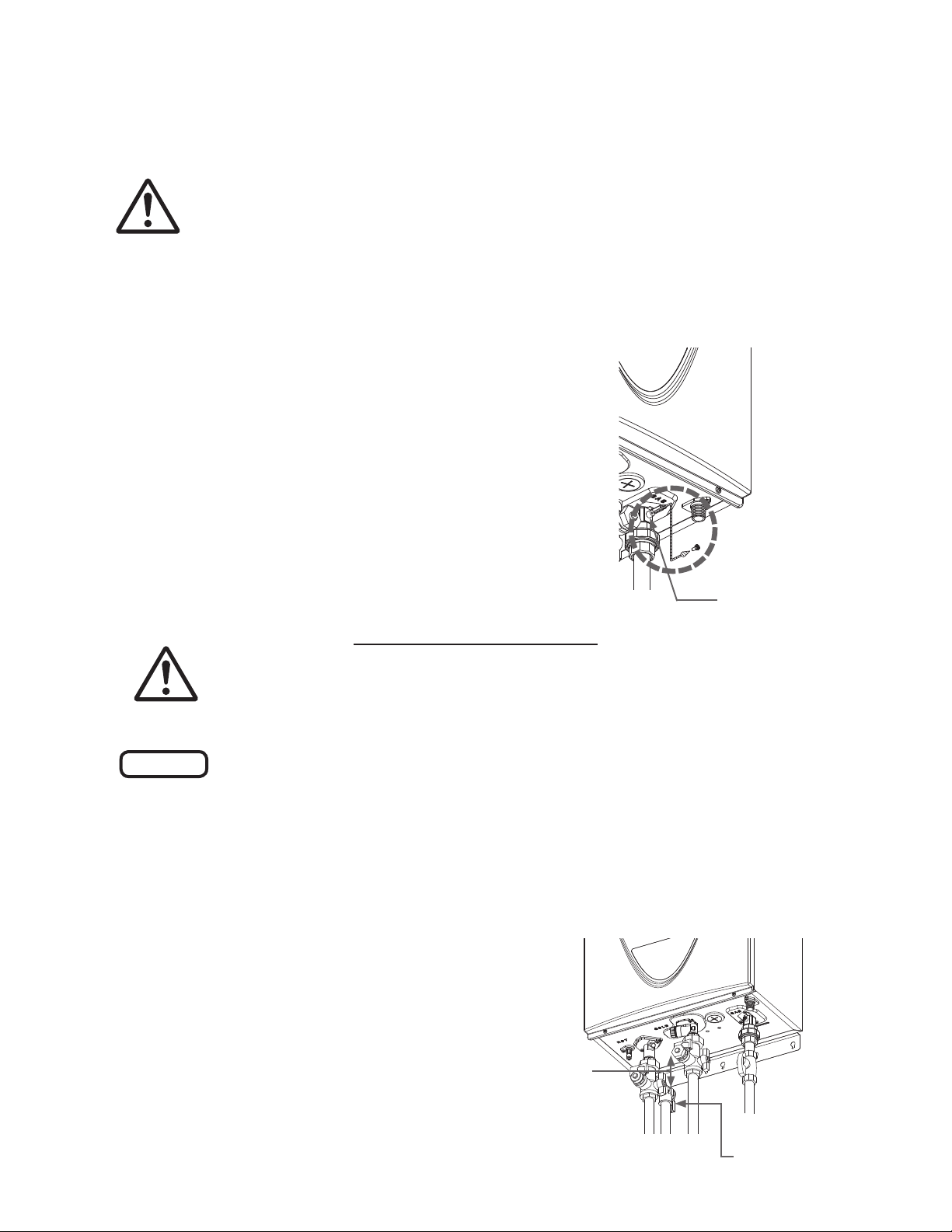
1. Shut off the manual gas valve on the gas supply line.
2. Remove the screw for the pressure port located on the
gas inlet of the micro boiler shown in the diagram on the
right.
3. Connect the manometer to the pressure port.
4. Re-open the manual gas valve. Check to see that there
are no gas leaks.
5. Check in inlet gas pressure. When the micro boiler is on
maximum and minimum burn, the manometer should
read from 5.0” W.C. to 10.5” W.C. (1.24 to 2.61 kPa) for
Natural Gas, from 8.0” to 14.0” W.C. (1.99 to 3.48 kPa)
for Propane.
The micro boiler cannot perform properly without sufcient inlet gas pressures. Below are instructions
on how to check the inlet gas pressure. THIS IS ONLY TO BE DONE BY A LICENSED PROFESSIONAL.
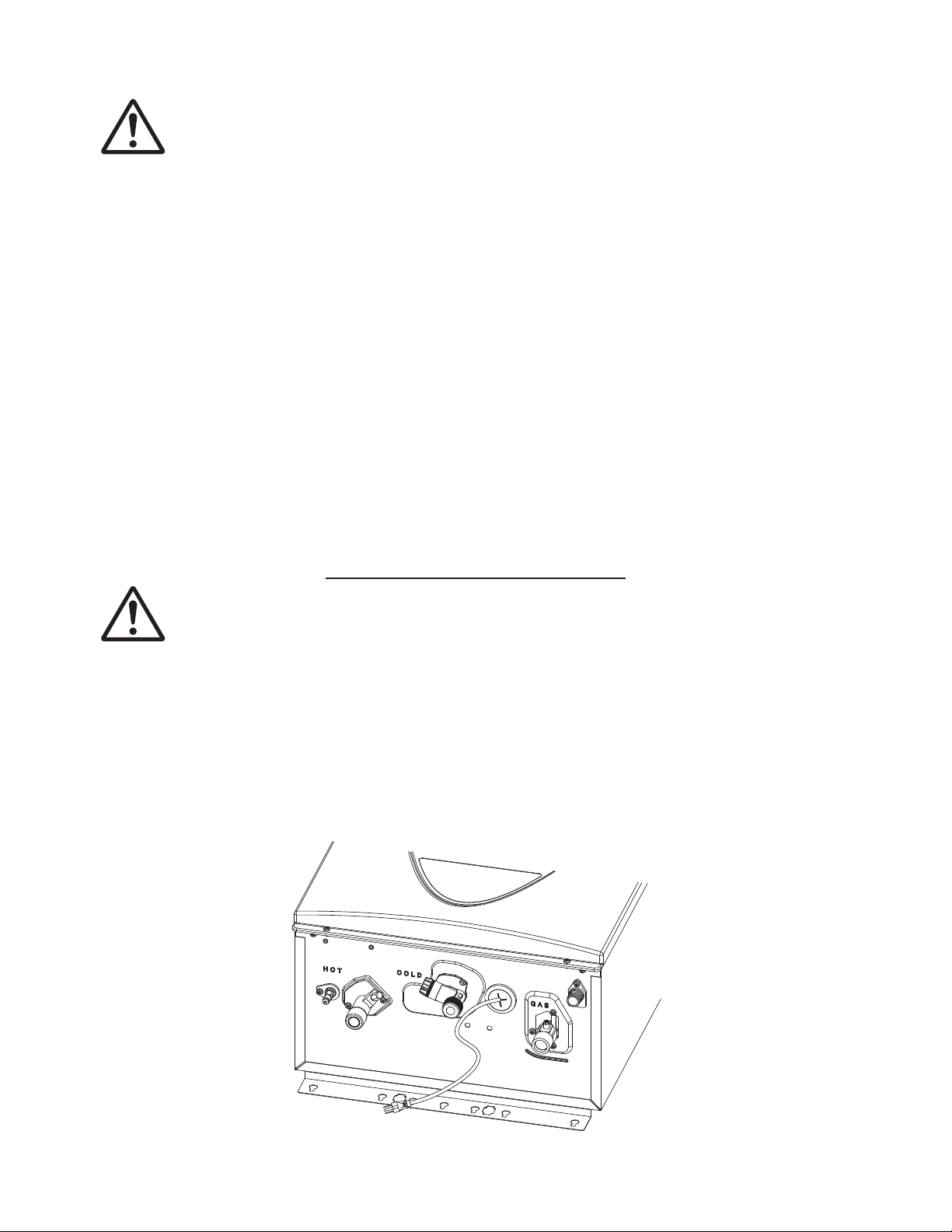
WATER CONNECTIONS
Do not use the micro boiler if any part has been under water. Immediately
contact a qualied installer or licensed professional to inspect the boiler to
determine if it needs to be replaced.
Do not reverse the hot outlet and cold inlet connections to the micro boiler.
This will not properly activate the micro boiler.
All pipes, pipe ttings, valves and other components, including soldering materials, must be suitable
for potable water systems (when using combi panel), or distilled water or distilled water/glycol mix.
1. A manual shutoff valve must be installed on the cold water inlet to the micro boiler between the
main water supply line and the micro boiler.
2. In addition, a manual shutoff valve is also recommended on the hot water outlet of the unit. If the
micro boiler is installed within, or subjected to,
a closed loop system (recommended), a ther-
mal expansion tank or code approved device
to handle the thermal expansion must be
installed.
3. Before installing the micro boiler, ush the
water line to remove all debris, and after in-
stallation is complete, purge the air from the
line. Failure to do so may cause damage to the
boiler.
NOTICE
WARNING
WARNING
Pressure port
Cold
Hot
inlet
outlet
Gas inlet
As Close as
Possible
Pressure relief valve
24
Pressure relief valve
The micro boiler has a high-temperature shutoff switch built in as a standard safety feature (called a
Hi-Limit switch) therefore a “pressure only” relief valve is required.
• This unit does not come with an approved pressure relief valve.
• An approved pressure relief valve must be installed on the hot water outlet.
• The pressure relieve vale must conform to ANSI Z21.22 or Can 1-4.4 and installation must follow
local codes.
• The discharge capacity must be at least 199,000 BTU/h.
• The pressure relief valve needs to be rated for a maximum of 150 psi (1 MPa).
• The discharge piping for the pressure relief valve must be directed so that the hot water cannot
splash on anyone or on nearby equipment.
• Attach the discharge tube to the pressure relief valve and run the end of the tube to within 6
in.(152 mm) from the oor. This discharge tube must allow free and complete drainage without any
restrictions.
• If the pressure relive valve installed on the micro boiler discharges periodically, this may be due to
a defective thermal expansion tank or defective pressure relief valve.
• The pressure relief valve must be manually operated periodically to check for correct operation.
• No valve must be placed between the relief valve and the micro boiler.
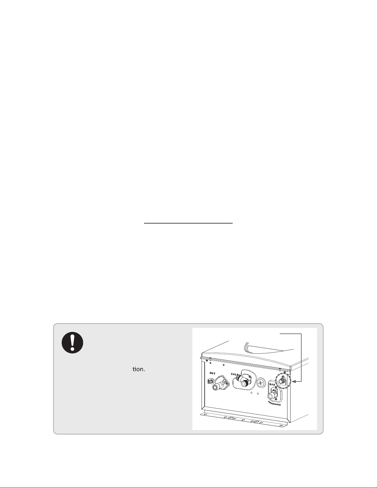
CONDENSATE DRAIN
• The micro boiler does not include a built-in condensate neutralizer cartridge for reducing the pH
level of condensate water. If local codes dictate that condensate must be neutralized prior to
drainage, a condensate neutralizer must be installed. An accessory Neutralizer assembly is sold
separately.
• In the absence of applicable local codes and regulations, th manufacture recommends that con-
densate be disposed of into a standard drain. Connect a drain tube from the condensate drain port
(shown below) located on the bottom of the micro boiler to a standard drain.
Follow all code requirements
of the local authority on
condensate neutralizers and
whether or not they are required
for the installa
Condensate drain port
25
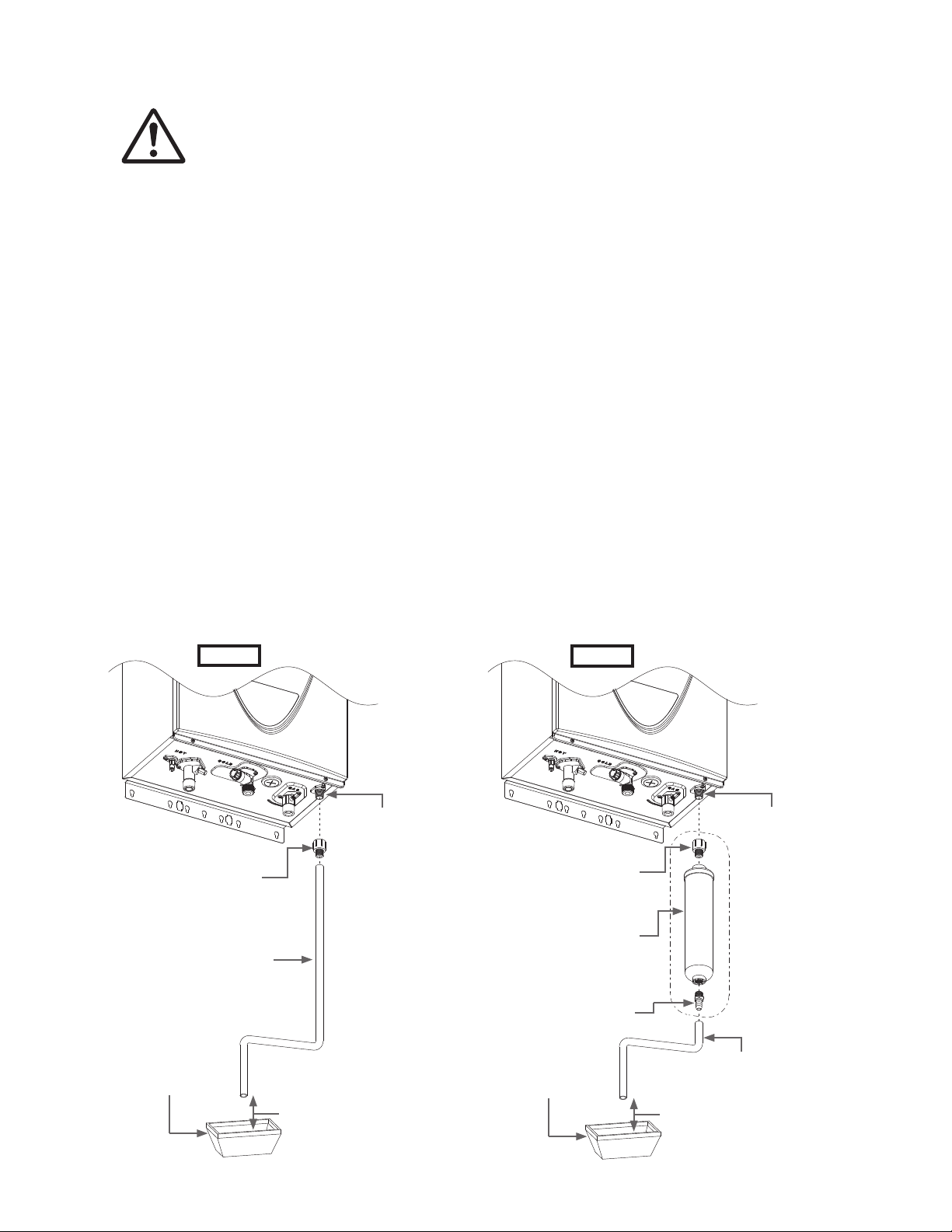
Condensate Drain Connections
Discharge condensate (acidic water) in accordance with all local codes
and common safety practices.
The micro boiler is a high efciency condensing micro boiler that produces condensate (acidic water).
The acidic condensate generated in the secondary heat exchanger can be neutralized by the Neutral-
izer accessory.
1. Connect a 1/2” FPT X 3/8” (or 1/2”) HB Adaptor to the condensate drain port at the bottom of the
micro boiler.
2. Connect a condensate drain tube to the 1/2” FPT X 3/8” (or 1/2”) HB Adaptor. The manufacturer
recommends the material of the condensate tube be either EPDM or PVC.
3. Leave an adequate amount of space between the end of the drain tube and the actual drain, to
facilitate proper drainage.
Case A: If a neutralizer is not required
1. Connect a 1/2” FPT X 3/8” (or 1/2”) HB Adaptor to the condensate drain port at the bottom of the
micro boiler.
2. Connect the Neutralizer to the 3/8” MPT connection of the adapters. There is a ow direction
indicator on the neutralizer. Please orient the neutralizer in the proper direction.
3. Connect a 1/2” drain tube to the other end of neutralizer.
4. Leave an adequate amount of space between the end of the drain tube and the actual drain, to
facilitate proper drainage.
Case B: If a neutralizer is required (installing the Neutralizer assembly)
WARNING
Condensate
drain port
1/2" Condensate
drain tube
Adequate space
Drain
Drain
3/8" or 1/2"
Condensate
drain tube
Condensate
drain port
1/2" FPT x 3/8"
(or 1/2") HB
1/2" FPT x 3/8" MPT
(Included with
Neutralizer accessory)
Neutralizer cartridge
(Included with
Neutralizer accessory)
3/8" MPT x 1/2" HB
(Included with
Neutralizer accessory)
Adequate space
Case A
Case B
26
• The condensate drain is at atmospheric pressure (non-pressurized) and
therefore must be allowed to drain freely with gravity only. Please ensure that
there are no blockages along the condensate drain tube. All portions of the
condensate drain (neutralizer and drain tube) must be at a lower eleva-
tion than the micro boiler to prevent condensate water from building up
inside the heat exchanger.
• Condensate cannot be effectively neutralized if the neutralizer elements inside
the Neutralizer accessory have been completely consumed. if this happens,
condensate will remain acidic and can possibly cause damage to items such
as pipes, concrete, etc., if drained improperly.
• The neutralizer cartridge is designed to last for 3 years before replacement.
However, the actual life of the neutralizer may vary, depending on the applica-
tion and usage. Please ensure that the cartridge is properly replaced before
the neutralizer elements have been completely consumed.
• All preventive measures and safety practices must be adhered to when drain-
ing condensate. The manufacturer will not be responsible for any damage
caused by condensate.
• A drain pan, or other means of protection against water damage, is required to
be installed under the micro boiler in case of leaks.
ELECTRICAL CONNECTIONS
• Follow the electrical code requirements of the local authority having jurisdic-
tion. In the absence of such requirements, follow the current edition of the Na-
tional Electrical Code ANSI/NFPA 70 in the U.S. or the current edition of CSA
C22.1 Canadian Electrical Code Part 1 in Canada.
• When servicing or replacing parts with the micro boiler, label all wires prior to
disconnection to facilitate an easy and error-free reconnection. Wiring errors
can cause improper and dangerous operation. Verify proper operation after
servicing.
• Failure to observe these warnings could result in personal injury or loss of life.
This unit comes with a power plug instead of a junction box.
WARNING
WARNING
27
APPLICATIONS
Space Heating Applications
• In order to purge air in water pipes within a closed loop system, an air vent,
air separator, and expansion tank should be installed in the system. (Hydro
Smart pre-built space heating panels incorporate all of these features).
• Water temperature over 125° F (52° C) can cause sever burns instantly of
death from scalding.
• Chemicals such as diluted Glycol can be used for radiant oor, Hydro/fan
coil air or Baseboard heating only. The diluted solution of glycol must contain
between 25% and 55% of Glycol. Be aware that in a closed loop system, low
pressure in the heat exchanger can cause low-temperature boiling, resulting
in excessive noise and damage to the micro boiler. Consult with the glycol
maker for specications prior to use.
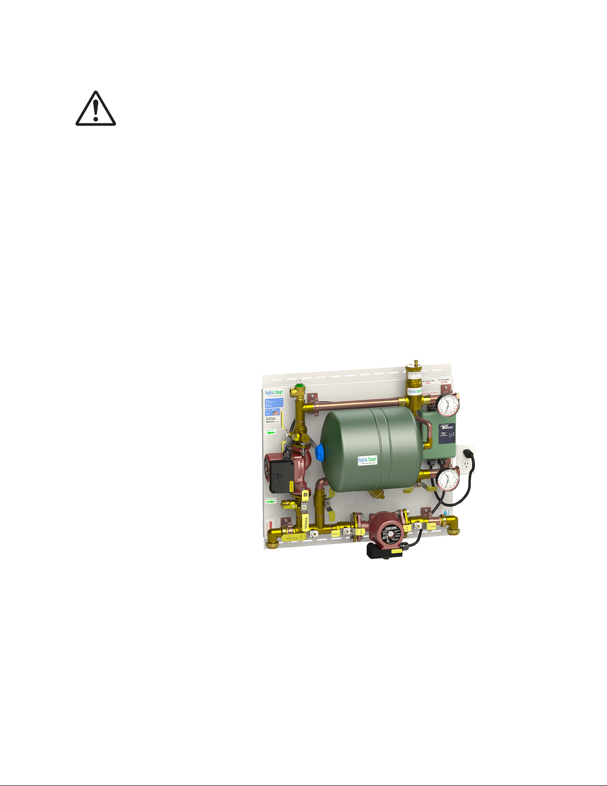
Hydro Smart Pre-Built Space Heating Panels
Hydro Smart per-plumbed panels help make space heating easy and reliable. These panels are
professionally engineered and use proven Primary/Secondary hydronic practices. Call Tech Support
(1-763-331-3066) for assistance.
WARNING
HSPS190HT 1 Zone Panel:
For more information on Hydro Smart pre-plumbed panels and zoning options for this boiler please
visit www.hydro-smart.com or call 763-331-3066.
Sample:
28
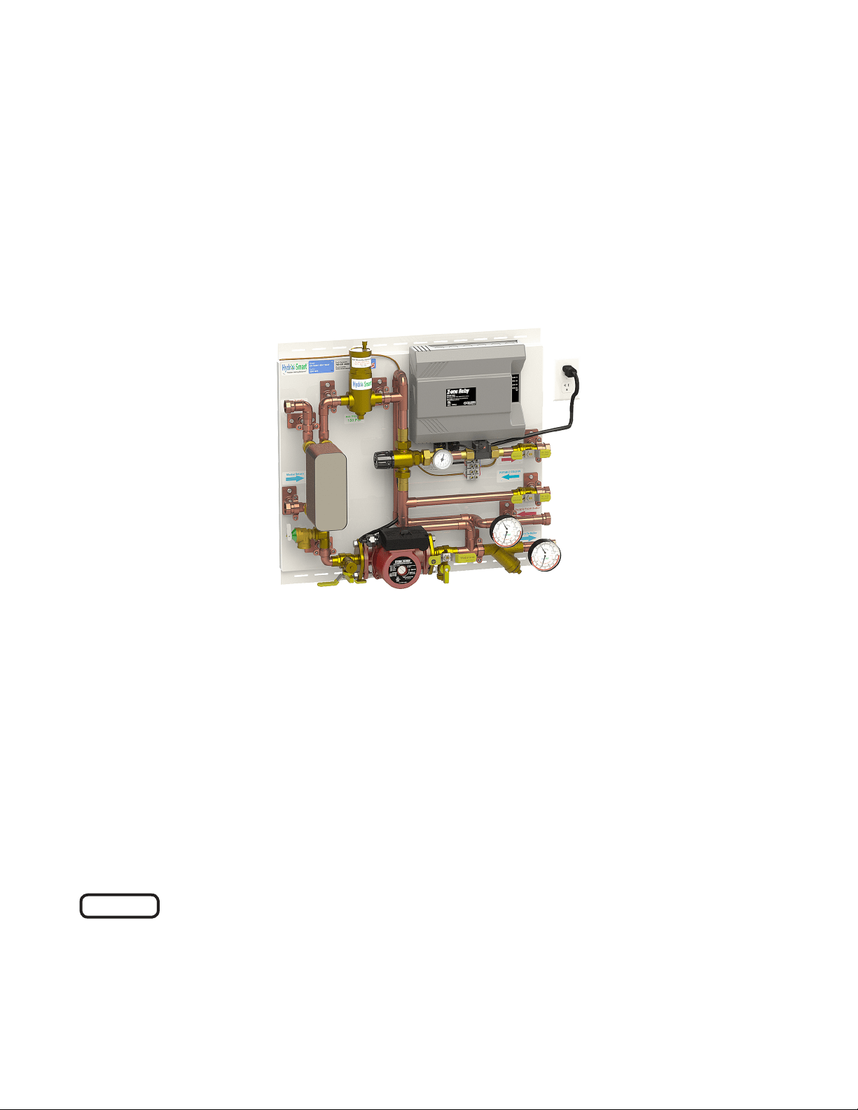
Dual-purpose hot water heating
(Domestic and Space Heating)
Insert a Hydro Smart Combi Panel to provide potable heated water and Hydronic Heating (with space
heating panel(s)) with one heat source.
The Hydro Smart Combi Panel integrates with a wide variety of boilers and delivers “Priority” potable
heated water with no storage tank and hydronic space heating in a small reliable package.
Follow all local codes, or in the absence of local codes, follow the most recent
edition of the National Standard Code, ANSI Z21.10.3.
For more information on Hydro Smart Combi panels and integrating space heating and domestic wa-
ter for this boiler please visit www.hydro-smart.com or call 763-331-3066.
NOTICE
29
INITIAL OPERATION
• Check the Gas and Water Connections for leaks before ring the unit for the rst time.
• Open the main gas supply valve to the unit using only your had to avoid and spark. Never use
tools. If the knob will not sure by had, do not try to force it; call a qualied service technician.
Forced repair may result in a re or explosion due to gas leaks.
• Be sure to check for the presence of leaking gas toward the bottom of the unit because some gas-
es are heavier than air and may settle towards the oor.
• Check the Gas Pressure.
• Do not try to light the burner manually. It is equipped with an electric ignition device which auto-
matically lights the burner.
• Check for proper venting and combustible air to the micro boiler.
• Purge the gas and water lines to remove any air pockets.
• Do not use this micro boiler if any part has been under water. Immediately call a qualied installer
or service technician to inspect the micro boiler to determine if it needs replacement.
• Do not try to start the micro boiler.
• Do no touch any electric switches; do not use any phone in your building.
• Immediately call your gas supplier from a neighbor’s phone. Follow the gas
supplier’s instructions.
• If you cannot reach your gas supplier, call the re department.
IF YOU SMELL GAS:
WARNING
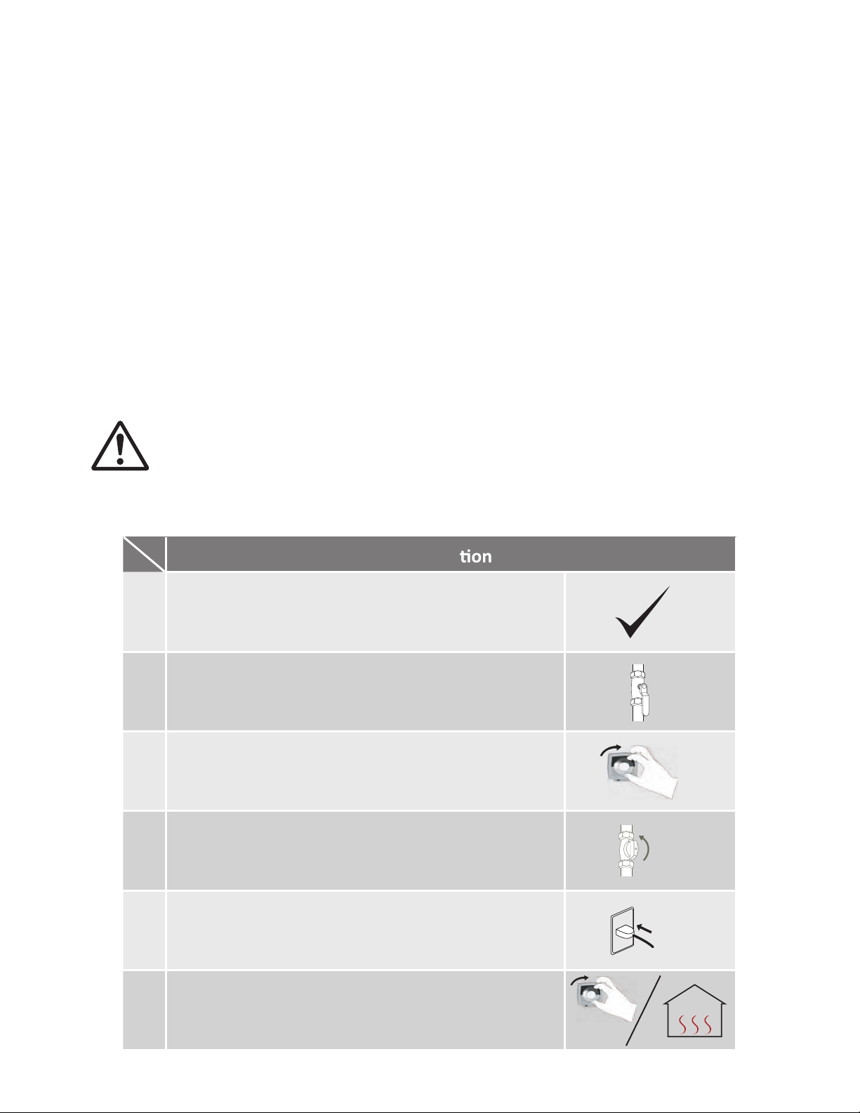
1.
Opera
2.
3.
4.
Turn on the thermostat and verify that fluid flows
through your radiant system. Then turn off your
thermostat.
Once the above checks have been completed, please clean
filter of any debris.
5.
Fully open the manual water control valve on the water
supply line.
Fully open the manual gas control valve installed.
6.
Now turn on the thermostat. You are ready to enjoy hours
of endless comfort.
T
urn on the 120 VAC, 60 Hz power supply to the water
heater.
30
Owner’s Guide
CONGRATULATIONS
Congratulations and thank you for choosing our condensing micro
boiler. Before use, we recommend that you read through this owner’s
guide carefully. Keep this manual for future reference.
If you need an additional manual, contact the manufacturer or your
local distributor. When you call, please tell us the product name and
the serial number of your unit written on the rating plate of the boiler.

31
OPERATING SAFETY
FOR YOUR SAFETY READ BEFORE OPERATING
WARNING: If you do not follow these instructions exactly, a re or explosion may result
causing property damage, personal injury or loss of life.
1. The micro boiler does not have a pilot. It is equipped with an ignition device that automatically
lights the burner. Do NOT try to light the burner by hand.
2. Before operating smell all around the micro boiler area for evidence of leaking gas. Be sure to
smell next to the oor because some gas is heavier than air and will settle on the oor.
WHAT TO DO IF YOU SMELL GAS:
• Do not try to light any appliance.
• Do not touch any electric switch; do not use any phone in your building.
• Immediately call your gas supplier from a neighbor’s phone.
• Follow the gas suppliers instructions. If gas supplier cannot be reached, call re dept.
3. Use only your hand to turn the gas shutoff valve. Never use tools. If the valve will not turn by hand,
don’t try to repair it, call a qualied service technician. Force or attempted repair may result in a
re or explosion.
4. Do not use this micro boiler if any part has been under water. Immediately call a qualied service
technician to inspect the micro boiler and to replace the unit if needed.
OPERATING INSTRUCTIONS
1. STOP! Read the safety information above or in the Owner’s Manual.
2. Turn off all electric power to the micro boiler.
3. Do not attempt to light the burner by hand.
4. Turn the manual as valve located on the outside of the unit clockwise to the OFF position.
5. Wait ve (5) minutes to clear out any gas. If you then smell gas, STOP! Follow “B” in the safety
information above on this label. If you don’t smell gas, go to next step.
6. Turn the manual gas valve located on the outside of the unit counterclockwise to the ON position.
7. Turn on all electrical power to the micro boiler.
8. If the micro boiler will not operate, follow the instructions “To turn off Gas to appliance” and call
your service technician or gas supplier.
TO TURN OFF GAS TO APPLIANCE
1. Turn off all electric power to the micro boiler if service is to be performed.
2. Turn the manual gas valve located on the outside of the unit clockwise to the OFF position.
32
Vapors from ammable liquids will explode and catch re causing death or sever burns.
Do not use or store ammable products such as gasoline, solvents or adhesives in the same
room or area near the micro boiler.
1. Far away from boiler.
2. In approved containers.
3. Tightly closed and out of reach of children.
4. Micro boiler has a main burner, which may
come on at any time and will ignite am-
mable vapors.
DANGER
1. Cannot be seen.
2. Are heavier than air.
3. Go a long way on the oor.
4. Can be carried form other rooms to the
main burner by air currents.
Keep ammable products: Vapors:
Read and follow micro boiler warnings and instructions. if the owner’s manual is miss-
ing, contact the manufacturer.
DANGER
1. Water temperature over 125° F can cause severe burns instantly or death from scalds.
2. Children, disabled and elderly are at highest risk of being scalded
3. Feel water before bathing or showering.
4. Temperate limiting valves are available on the Combi Panel(s). Adjust these mixing valves accord-
ingly.
5. The outlet temperature of the micro boiler is set at 120° F (50° C). If you require water tempera-
tures below this setting, follow the instruction manual.
6. Test the boiler before bathing or showering. Do not leave children or an infrim person unsuper-
vised.
When using micro boiler with Combi Panel for Domestic Hot Water:
Flammable Vapors
33
NORMAL OPERATION
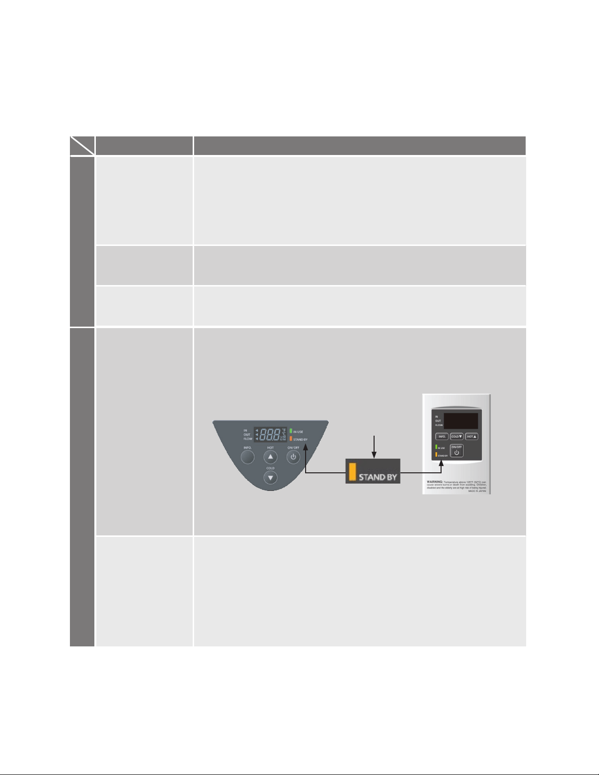
TEMPERATURE CONTROLLER AND REMOVE CONTROLLER
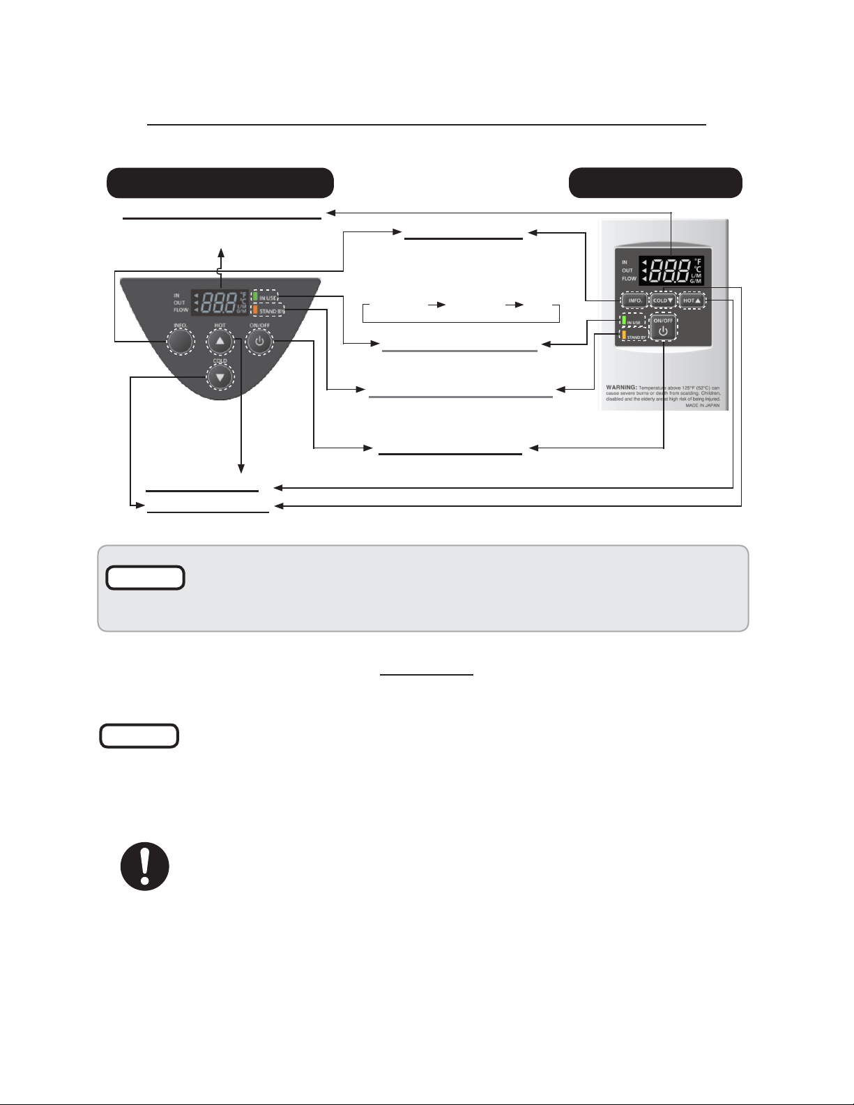
The illustration below shows an example of the controllers. The exact display may differ from examples.
GENERAL
• Flow rate to active micro boiler: 0.5 gallon per minute at the default set
temperature
• Flow rate to keep the micro boiler running: 0.4 gallon per minute.
• The controllers have an energy saving mode. Five minutes after the micro
boiler stops operating, the back-light of the controllers turn off.
• The back-light of the controllers will turn back on once the micro boiler be-
gins ring again.
STAND BY LED (Orange)
"HOT" Buon
"COLD" Buon
Press the "HOT" buon or the "COLD"
buon to set the hot water temperature.
IN USE LED (Green)
The indicator is ON to show that
power is ON.
The indicator lights during combuson.
"INFO" Buon
Inlet water
Each me the buon is pressed,
the operaon mode is selected
in the sequence of the following.
temperature
Outlet water
temperature
Water
flow
Built-in controller
Display for Temperature
When the STAND BY LED is ON, the
hot water temperature will be
displayed.
"ON/OFF" Buon
Remote controller
Press this buon to
start or stop operaon.
NOTICE
• When the remote controller is installed it will take priority over the built-in controller.
• The controller has an energy saving mode. Five minutes aer the water heater stops
operang, the backlight of the controller turns off.
• The backlight of the remote will turn back on once the water heater begins firing again.
Temperature Controller
NOTICE
34
Set Temperature
TEMPERATURE SETTINGS
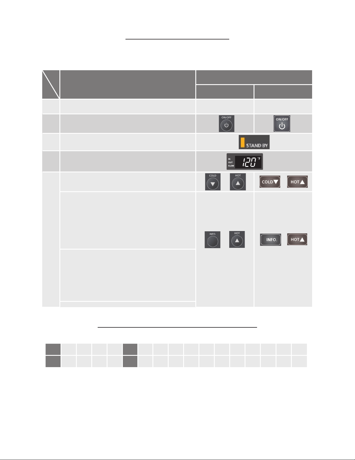
TEMPERATURE TABLE OF CONTROLLER
Operaon
Screen on the controller
Built-in controller
1.
Remote controller
2.
Turn on the 120 VAC power supply to the unit.
3.
Press the "ON/OFF" buon on the controller in order to
turn the controller on.
4.
When ON, the STAND BY LED is lit.
5.
It shows the set temperature on its display as shown in
the picture on the right. (EX.: 120 °F)
Press the "HOT" buon or the "COLD" buon to set the
temperature seng of the unit.
Increasing temperature from 120 °F (50 °C) to 125 °F (52 °C) :
Increasing temperature above 140 °F (60 °C)
1. The micro boiler must be in Stand By to increase the
temperature.
2. Press the "HOT" buon to set 120 °F (50 °C).
3. Press and hold the "INFO" buon and the "HOT"
buon for a
t least 3 seconds. The remote will emit a
beep and change to 125 °F (52 °C).
4. Press the "HOT" buon to set up to 140 °F (60 °C).
(EX.: 120 °F)
1. The micro boiler must be in Stand By to increase the
temperature.
2. Press the "HOT" buon to set 140 °F (60 °C).
3. Press and hold the "INFO" buon and the "HOT"
buon for at least 3 seconds. The remote will emit a
beep and change to 145 °F (63 °C).
4. Press the "HOT" buon to set up to 160 °F (70 °C).
155 160
°C
°F 100 105 110 115 120* 125 130 135 140 145 150
38 40 43 45 50* 52 55 57 60 63 65 68 70
*Factory seng (Default): 120 °F
165 175
75 80
185
85
35
ADDITIONAL FEATURES
Information mode
You can get some information about the micro boiler condition by pressing “Info” button. For more
information, follow the procedures below:
Unit Conversion Mode
The remote controller has a function that can change units of temperature and ow rate from °F to
°C and from gallon per minute to liter per minute and vice versa, please follow the procedure below.
When the micro boiler is connected with the remote controller, the temperature
controller will not operate temperate settings, as only work for the information
mode.
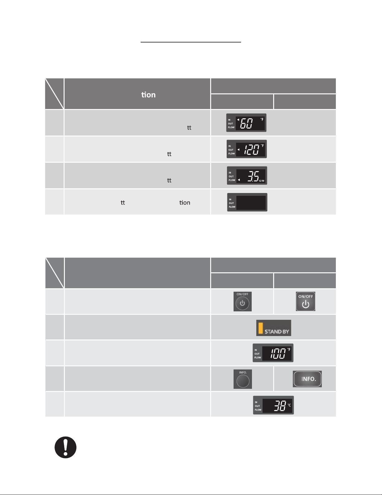
Opera
Screen on the controller
1.
Temperature controller Remote controller
2.
First of all, inlet water temperature will be displayed
on the controller by pressing the "INFO" bu
on.
3.
Outlet water temperature will be displayed on the
controller by pressing the "INFO" bu
on.
4.
Press the "INFO" bu on to finish informa mode.
And then, water flow will be displayed on the
controller by pressing the "INFO" bu
on.
Inlet water temperature
(EX.: 60 °F)
Water flow
Outlet water temperature
(EX.: 120 °F)
(EX.: 3.5 GPM)
Operaon
Screen on the controller
Built-in controller
1.
Remote controller
2.
Press the "ON/OFF" buon on the controller in
order to turn the controller on.
3.
When ON, the orange LED is lit.
4.
The previous set temperature will be displayed on
the screen.
5.
Press the "INFO" buons for at least 3 seconds.
The set temperature should now be displayed in the
alternate unit of measurement.
(EX.: 100 °F)
(EX.: 38 °C)
36
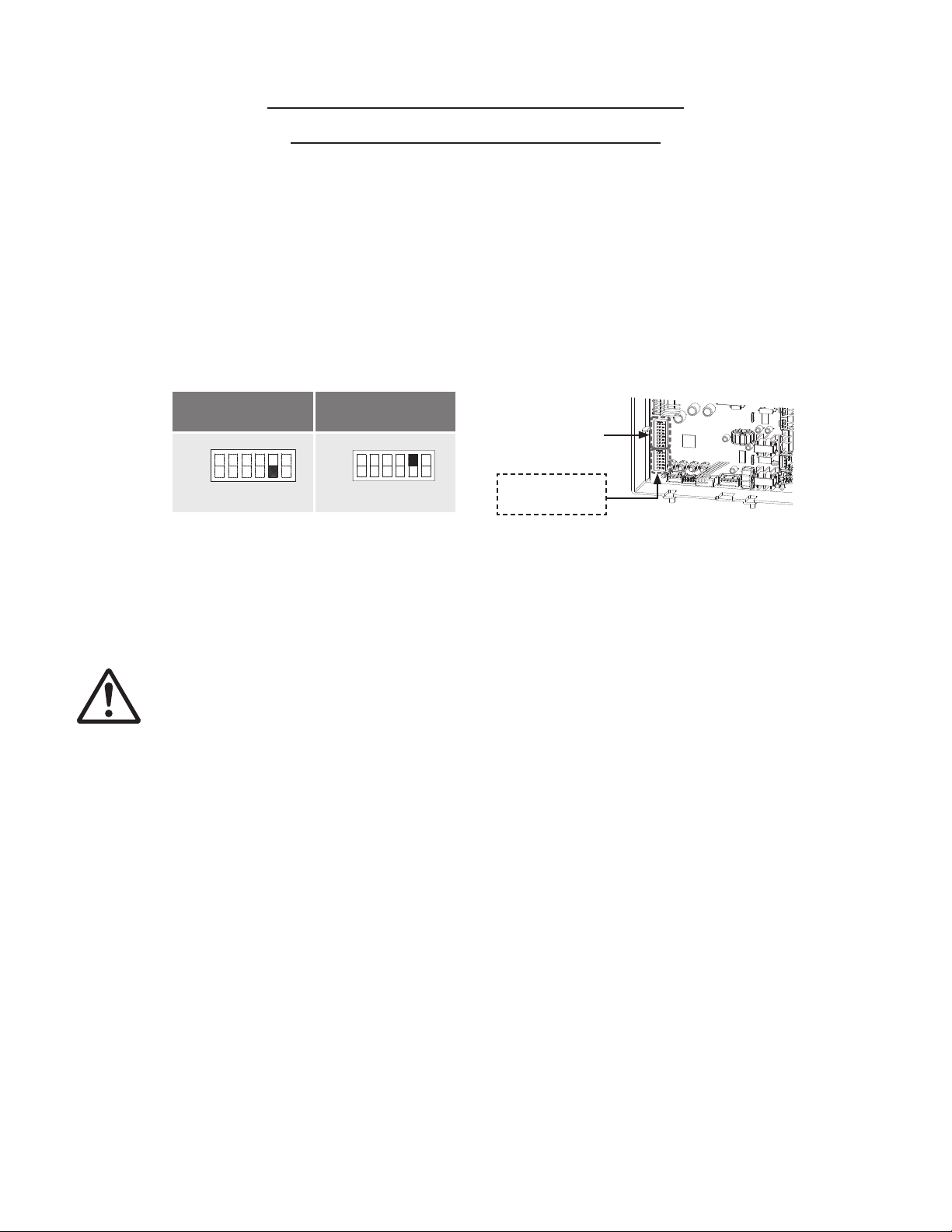
TEMPERATURE SETTINGS ON THE PCB
(WITHOUT REMOTE CONTROLLER)
There are 2 preset DIPswitches (120° F (50° C) and 140° F (60° C)) that you can select from by
changing the DIPswitch settings on the computer board without the remote controller. See the table
below. When the remote controller is in normal operation, the set temperature of the remote controller
is given priority over th set temperature of the DIPswitch settings.
• The temperature has been preset at the factory to 120° F (50° C).
• DO NOT adjust the upper bank of DIPswitches
• Turn off the power supply to the micro boiler before changing the DIPswitch settings.
NOTE: Only change the switches with dark squares. The dark squares indicate the
direction the DIPswitches should be set to.
(Lower bank of DIPswitches)
140 °F (60 °C)
120 °F (49 °C)
DEFAULT
No. 5 : OFF No. 5 : ON
ON
1 2 3 4 5 6
OFF
ON
1 22 33 44 55 66
OFF
Computer board
Upper bank of
DIPswitches
Lower bank of
DIPswitches
WARNING

37
FLOW
• The ow rate through the micro boiler is limited to a maximum of 10.0 GPM (38 L/min).
• The temperature setting, along with the supply temperature of the water will determine the ow
rate output of the unit.
FREEZE PROTECTION SYSTEM
• This unit comes equipped with heating blocks to protect it against damages associated with freez-
ing.
• For this freeze protection system to operate, there has to be electrical power to the unit. Damage
to the heat exchanger caused by freezing temperates due to a power loss is not covered under
warranty. In cases where power losses can occur, consider the use of a backup power supply.
• The freeze protection system will activate when the surrounding and/or outside temperature drop.
• It is the installer’s responsibility to be aware of freezing issues and take all preventive measures.
The manufacture will not be responsible for any damage to the heat exchanger as a result of
freezing.
• In any area subject to freezing temperatures, freezing issues can occur if cold air enters through
the venting into the heat exchanger by either negative pressures within the installation location or
by strong outside wind. The manufacturer highly recommends the use of a back ow preventer
(sold separately) to minimize the amount of cold air entering through the exhaust venting when the
micro boiler is off.
• It is the installer’s responsibility to be aware of freezing issues and take all preventive measures.
The manufacture will not be responsible for any damage to the heat exchanger as a result of
freezing.
• If you will not be using your boiler for a long period of time:
1. Completely drain the water out of the unit.
2. Disconnect power to your boiler.
This will keep your unit from freezing and being damaged.
Only pipes within the micro boiler are protected by the freeze protection system.
Any water pipes (hot or cold) located outside the unit will no be protected. Properly
protect and insulate these pipes from freezing.
CAUTION
38
MAINTENANCE AND SERVICE
Turn off the electrical power supply and close the manual gas shutoff valve
and the manual water control valve before servicing.
• Be sure that all openings for combustion and ventilation air are not blocked.
• The venting system should be checked annually for any leaks, corrosion, blockages or damage.
• The burner should be checked annually for dust, lint, grease or dirt.
• Keep the area around the micro boiler clear. Remove any combustible materials, gasoline or any
ammable vapors and liquids.
• In accordance with all local codes and common safety practices, water discharged from the pres-
sure relief valve can cause severe burns instantly from scalding. DO NOT touch the pressure relief
valve.
• If the relief valve discharges periodically, it may be due to thermal expansion in a closed water
supply system. Contact the water supplier or local plumbing inspector on how to correct this situa-
tion.
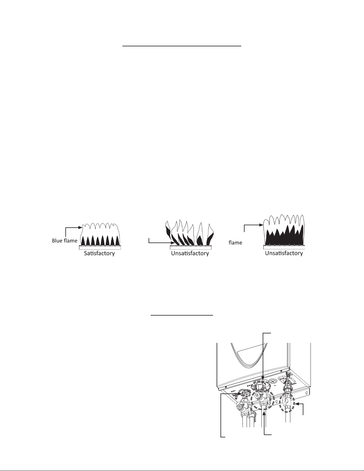
• Visual check of burner ames (see below) through the burner window in the burner assembly lo-
cated at the middle of the micro boiler.
The manufacturer recommends having the unit checked once a year or as necessary by a licensed
technician. If repairs are needed, any repairs should be done by a licensed technician.
UNIT DRAINING
1. Close the manual gas shutoff valve.
2. Turn off power to the unit and wait a couple of
seconds.
Turn on again.
3. Wait 30 seconds, and then turn off power to
the unit, yet again.
4. Close the water shut off valve.
5. Have a bucket or pan to catch the water from
the unit’s drain plugs. Unscrew the two drain
plugs (large and small) to drain all the water
out of the unit.
6. Wait a few minutes to ensure all water has
completely drained from the unit.
Flame
blowing up
Red or Yellow
Gas
Water valve
valve
(Small)
Drain plug
Drain plug
(Large)
39
TROUBLESHOOTING
General
PROBLEM SOLUTIONS
TEMPERATURE and AMOUNT OF HOT WATER
The water is not hot
enough.
The water is too hot. • Is the set temperature set too high?
The hot water is not
available when there
is a call for heat.
• Compare the flow and temperature.
• Check cross plumbing between cold water lines and hot water lines.
• Is the gas supply valve fully open?
• Is the gas line sized properly?
• Is the gas supply pressure sufficient?
• Is the set temperature set too low?
The hot water turns
cold and stays cold.
Fluctua
in hot
water temperature.
• Make sure the unit has 120 VAC, 60 Hz power supply.
• If you are using the remote controller and/or temperature controller, is
the power bu
on turned on?
• Is the gas supply valve fully open?
• Is the water supply valve fully open?
• Is the unit frozen?
• Is ther
e
enough
gas
in
the t
ank /
cy
linde
r? (For
Propane models)
• Is the flow rate enough to keep the micro-boiler running?
• Is the gas supply valve fully open?
• Are the fixtures clean of debris and obs
• Check if the flow rate is too low.
• Is the gas line sized properly?
• Is the supply gas pressure sufficient?
• Check for cross c
between cold water lines and hot water lines.
40
PROBLEM SOLUTIONS
WATER HEATER
Unit does not ignite
when water goes
through the unit.
The fan motor is
sll spinning aer
operaon has stopped.
Unit sounds abnor-
mal while in opera-
on
• This is normal. Aer operaon has stopped, the fan motor keeps running
from 15 to 70 seconds in order to re-ignite quickly, as well as purge all the
exhaust gas out of the flue.
• Is the flow rate over 0.5 GPM (1.9 L/min)?
• Check for the filter on the cold water inlet.
• Check for reverse connecon and cross connecon.
• If you use the remote controller and/or temperature controller, is the
power buon turned on?
• Check if the inlet temperature is too high. If it is too close to the set
temperature, the water heater will not
acvate.
• Contact the manufacturer at 1-763-331-3066
BUILT-IN CONTROLLER AND
REMOTE CONTROLLER
Controller does not
display anything
when the power
turned on.
When the
controller turned
ON, STAND BY LED
is lit.
Built-in controller
• Make sure the unit is supplied with power.
• Make sure the connecon to the unit is correct.
NOTICE:
When the unit has not operated for five minutes or more, the display
of the controllers turns off to conserve energy.
An ERROR code is
displayed.
Although the controller of the parent unit will display the set
temperature at the Easy-Link System, the controller of the child unit
will not display the set temperature.
• Please see Error Code Secon.
buon is
Troubleshooting (Cont’d)
41
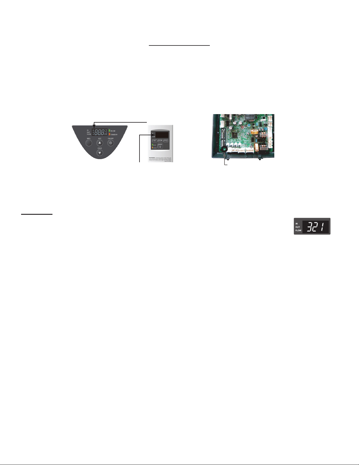
ERROR CODES
• The units are self-diagnostic for safety and convenience when troubleshooting.
• If there is a problem with the installation or the unit, the error code will be displayed on the tem-
perature controller and remote controller.
• Consult with the table on the following pages for the description of each error code.
Single unit installations
Example: if your unit has the “321” error code (which signies an inlet thermistor failure)
• Indicator on the temperature
controller or remote controller: “321” will be displayed on the screen in its entirety.
• Green LED on the computer board: The green LED on the computer board will be
blinking two times.
Error code indicator on
the temperature controller
Error code indicator on the remote
controller
Green LED
42
Fault Analysis of Error Codes
If the error code is displayed on the computer board of the micro boiler or remote controller and/or
temperature controller, please check the following. After checking, Consult with the manufacturer.
Remote
Green
LED
Diagnosis
descrip
031
One Time Incorrect DIPswitch
se
101
Five Times
• Check the DIPswitch se
on the PCB (Part #701).
Warning for the
“991” error code
111
Three Times failure
• Check the gas type of the micro-boiler.
• Check if there is any blockage in the intake air and/
or exhaust.
• If the micro-boiler is installed as a direct-vent
system, check whether there is enough distance
between the intake air terminal and the exhaust
terminal.
• Check the
/eleva of area of where the
micro-boiler is installed.
• Check if there is grease and/or dirt in the burner (Part
#101) and the fan motor (Part #103), especially if the
micro-boiler has been installed in a contaminated area.
121
Three Times Loss of flame
311
Two Times Heat exchanger
thermistor failure
321
Two Times
331
Inlet thermistor
failure
Two Times
341
Outlet thermistor
failure
• Check for connec
reakage of wires and/or
debris on thermistor (Part #407, 408, 411, 715).
Two Times
• Check if the Hi-limit switch (Part #412) is properly
• Check for connec reakage of wires (Part #413, 708,
709, 710, 712), burn marks on the computer board (Part
#701), and/or soot on the flame rod (Part #108).
• Check if there is a buzzing spark
sound
coming from the burner (Part #101) when
micro-boiler prepares for combus
• Listen for the double “clunk” sound coming from gas
valve assembly (Part #102) when micro-boiler goes
into combus
• Check if there is leaking from heat exchanger (Part #401).
• Check if the Hi-limit switch (Part #412) is properly
• Check for c reakage of wires (Part #413,
708, 709, 710, 712), burn marks on the computer
board (Part #701), and/or soot on the flame rod
(Part #108).
• Check if there is leaking from heat exchanger (Part #401).
Exhaust thermistor
failure
43
Remote
LED
Green
Diagnosis
descrip
391
Two Times Air-fuel ra rod
failure
441
Two Times
• Check for c
reakage of wires (Part #709)
and/or soot on the AFR rod (Part #108).
Flow sensor failure
(Easy-Link System only)
510
Six Times Abnormal main gas
solenoid valve
• Check for c
reakage of wires and/or
debris on the flow sensor impeller (Part #402).
551
Six Times Abnormal gas
solenoid valve
• Check for connec
reakage of wires (Part #708)
and/or burn marks on the computer board (Part #701).
611
Four Times Fan motor fault
• Check for connec
reakage of wires (Part #708)
and/or burn marks on the computer board (Part #701).
651
Four Times Flow adjustment
valve fault (Easy-
Link System only)
• Check for c
reakage of wires, dust buildup
in the fan motor (Part #103) and/or burn marks on
the computer board (Part #701).
• Check for frozen/corrosion of connectors (Part #103).
661
Four Times Bypass valve fault
701
One Time
• Inspect the flow adjustment valve (Part #402), for
c
reakage of wires, locked motor drive
due to scale buildup, and/or water leakage.
Computer board fault
711
One Time
• Inspect the bypass valve (Part #403), for c
breakage of wires, locked motor drive due to scale
buildup, and/or water leakage.
• Check for c
reakage of wires (Part #714).
721
Gas solenoid valve
drive circuit failure
Six Times
• Refer to the 111 and 121 error codes.
det
False flame
741
N/A Miscommunica
between micro-
boiler and remote
controller
• Check if condensate drain is installed on the vent
collar of the micro-boiler.
• Check if there is leaking from heat exchanger (Part #401).
751
N/A
• Check the model type of the remote controller.
• Inspect the c
between the micro-boiler
and remote controller.
• Check the power supply of the micro-boiler.
Miscommunica
between micro-boiler
and temperature
controller
761
N/A Miscommunica
in Easy-Link System
• Inspect the c
between the micro-boiler
and temperature controller.
• Check the power supply of the micro-boiler.
941
Five Times Abnormal exhaust
temperature
• Check if the c
between the parent unit
and the child units are correct.
991
Five Times Imperfect
combus
• Check if the set temperature is higher than 140°F
(60°C) and the system is Recircula
• Check the gas type of the micro-boiler.
• Inspect the environment around the micro-boiler.
Determine how long the unit has been installed.
• Check the eleva of the area of where
the micro-boiler is installed.
• Check if there is any blockage in the intake air and/
or exhaust.
• If the micro-boiler is installed as a direct-vent system,
check whether there is enough distance between the
intake air terminal and the exhaust terminal.
• Check if there is grease and/or dirt in the burner (Part
#101) and the fan motor (Part #103), especially if the
micro-boiler has been installed in a contaminated area.
44
COMPONENTS DIAGRAM
Case assembly
Temperature
remote controller
724
723
722
056
Temperature controller
052
052
003
007
002
050
702
704
008
052
050
052
717
713
004
001
004
45
Computer board assembly
Surge box assembly
121
713
703
706
709
063
053
703
701
714
403
715
721
707
722
715
402
402
103
713
708
711
709
716
46
Burner assembly
101
104
115
106
107
108
110
109
111
711
112
062
053
053
709
053
401
103
105
065
054
113
114
102
708
119
151
118
055
051
150
057
055
063
117
053
116
062
121
714
719
707
711
117
Manifold
assembly
Burner assembly
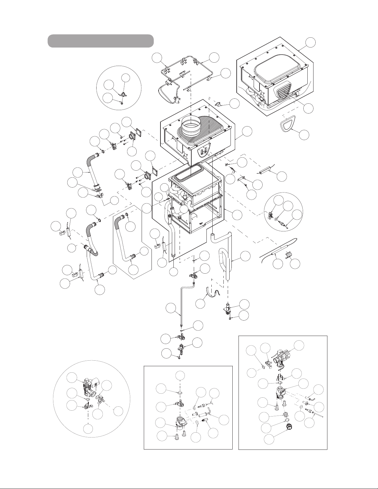
47
Water Way assembly
402
460
456
461
458
404
417
407
454
405
457
406
410
455
408
458
454
462
C
D
052
059
052
409
417
403
456
460
458
462
B
A
Bypass secon
D
A
E
459
454
411
412
058
F
413
452
450
414
451
414
418
416
009
C
453
468
468
052
455
463
455
469
052
463
462
467
064
462
462
473
466
466
415
451
465
418
414
464
471
064
D
472
153
152
053
718
470
415
401
B
E
F
473
451
458
458
458
458
458
540 model
240 and 340 models
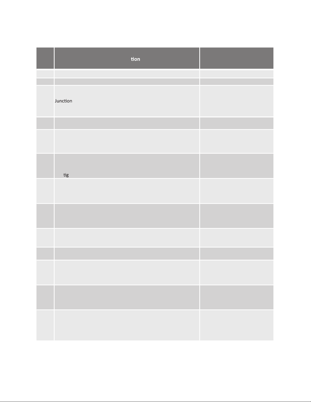
48
PARTS LIST
Item # Descrip
001
Part #
Case assembly
EK159
002 Front cover
EK158
003
004
005
006
007
EK170
EK162
EK190
EK171
EK161
008
009
EK160
EKH23
050
051
052
053
Chamber fixing plate
Condensate drain port
Intak
e air
port
assembly
Bracket
box
Power supply cord assembly
Back guard panel
EW000
EW001
EW002
EW003
054
055
056
057
Screw M4×12 (W/Washer)
Screw M4×10 (W/Washer)
Screw M4×10 (Coated)
Screw M4x10
EW004
EW005
EW018
EKK31
058
059
060
061
Screw M3x6
Screw M4x6
Screw M4x12
EW00A
EW009
Screw M3x6
EKK37
EK191
062
063
064
Hex head screw M4×12 (W/Washer)
Hex head screw M4x8
Pan screw M4x20
Tap
ht screw M4x12 FEZN
065
EW00D
EM167
EK230
EW00B
101
102
Pan screw M4x8
Wire clamp 60
Screw M4x10
Screw M3x6 SUS3
EK192
EK181
EK182
103 EK109
104
Fan motor
105
106
107
Burner assembly
Manifold with gas valve assembly LP
Manifold with gas valve assembly NA
EKK2X
EM381
Rod
holder
EKK2V
EKK2W
108
109
110
111
Flame rod
Burner gasket
Fan damper
Burner window
Rod holder gasket
Igniter rod
EK193
Rod cap
EKK0F
EKK32
EKN61
112
113
114
115
EK183
EK169
EKK2Y
EKK2K
EKK0G
Burner damper LP
Burner
damper NA
Mani
fold
gasket A
Manifold gasket B
Burner holder gasket
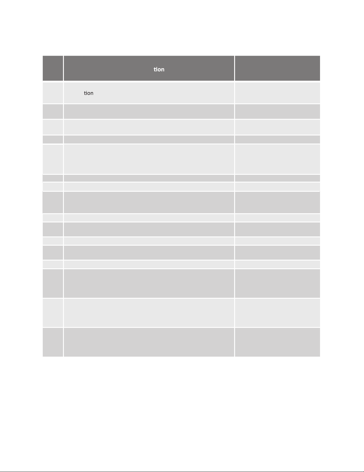
49
Item # Descrip
116
Part #
117
118
EKK2D
EX019
EK117
119
121
Pressure port
Combus chamber tube
Gas inlet
EX00D
EK163
150
151
Gas inlet ring
Surge box plate
EZP18
EK042
401
O-ring P18 NBR (Black)
O-ring P20 NBR (Black)
EK250
402
403
404
405
Primary heat exchanger
EK129
EKD58
EKK1U
EKK2B
407 EK137
408
Inlet thermistor
EKK1A
409
410
411
Outlet thermistor
Flow adjustment valve / Flow sensor
Bypass valve
Water inlet
Inlet drain plug
EK208
EKK2E
EKK2T
412 EKN34
413
414
Hi-Limit switch
Water outlet
Outlet drain plug
Heat exchanger thermistor
EK333
EK209
415 EK210
416
Overheat-cut-off fuse
Pipe heater
417
Inlet heater
Drain tube EK231
EK105
418
Inlet heater
EK251
450
451
452
453
Secondary heat exchanger
EKK27
EK031
EKK26
EK029
454
455
456
457
O-ring P4 FKM
O-ring P6 FKM
O-ring P14 FKM
EZM04
O-ring P15 FKM
EZM06
EZM14
EZM15
458
459
460
461
Pipe heater fixing plate
Heater fixing plate 16
Fuse fixing plate 18
Fuse fixing plate 14
EZM16
EKH30
EKK24
EM192
O-ring P16 FKM
Fastener “4-11”
Fastener “14-22”
Fastener “16A”
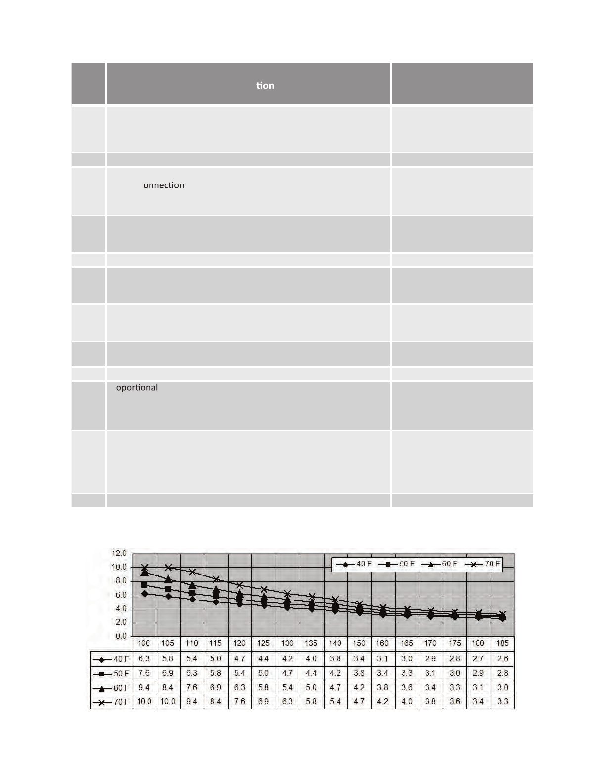
50
Item # Descrip
462
Part #
463
464
465
EKK39
EX12K
EK217
EK218
466 EK220Cold pipe
467
468
469
470
Fastener “16-25A”
Fastener “6-15”
Flat heater
Drain tube
EK222
EK226
EK228
EK13H
471
472
473
Stainless heat exchanger out pipe
Header c
Drain port
Thermistor fixing plate
EK13L
EKH6G
EK229
701 EK176
702
703
704
Computer board
Exhaust thermistor gasket
Hi-limit switch for exhaust
Gasket
EX00B
EK280
EK146
706
707
708
Rubber grommet
Surge box
120 VAC wire
EKK4V
EK165
EK168
709
711
EK166
EK153
713
Flame rod wire
Igniter assembly
120 VAC Power ON-OFF switch
Remote controller wire
Gas valve wire
EK184
714
715
716
717
Switch wire with thermostat
EM167
EK179
EKK1M
EX13C
718
719
721
722
723
Pr gas valve wire
24V cables
Computer board cover
Cable clamp
EKH6E
EK152
EK180
EK173
EK178
724 ER014Temperature remote controller
Exhaust
thermistor
Remote fixing plate
Exhau
st Hi-limit switch wire
Temperature controller
Fixing plate
*When the set temperature is 130 °F (55 °C) or higher, maximum flow rate is limited to 8.0 GPM.
Output Hot Water GPM
Output Temperature vs. GPM (Max. 10.0 GPM) with Various Inlet Water Temperature

51
NOTES: