- Do not store or use gasoline or other
ammable vapors and liquids in the
vicinity of this or any other appliance.
- WHAT TO DO IF YOU SMELL GAS
• Do Not try to light any appliance.
• Do not touch any electric switch, do
not use any phone in your building.
• Immediately call your gas supplier
from a neighbor’s phone. Follow the
gas supplier’s instructions.
• If you cannot reach your gas supplier,
call the re department.
- Installation and service must be
performed by a qualied installer,
service agency or the gas supplier.
FEATURING
• EFFICIENCY: 93%
• TEMP RANGE: 99° - 140°F
• COMPACT, SPACE SAVING
• FLOW ACTIVATED: .75 GPM
• COMPUTERIZED SAFETY
• NO PILOT LIGHT
• Satises the 2012 SCAQMD Rule
1146.2 for Ultra-Low NOx Emissions
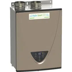
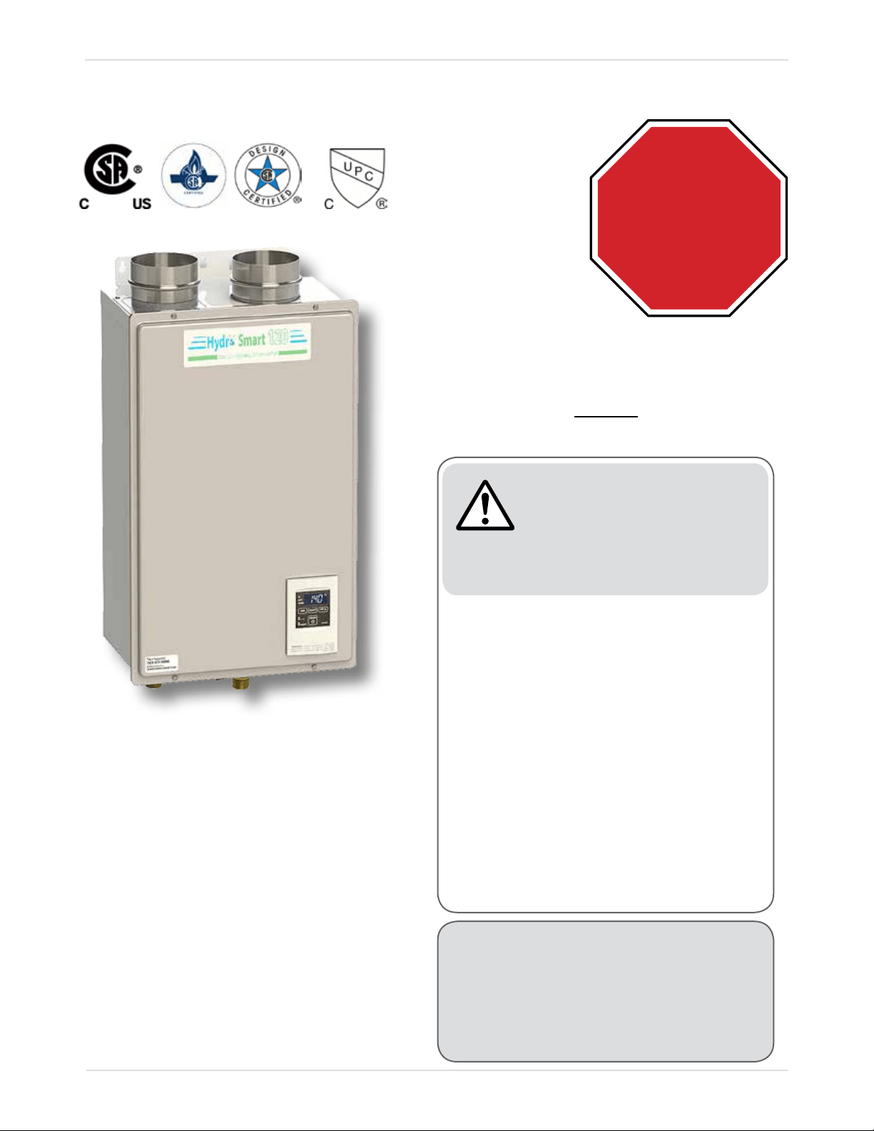
Hydro Smart 120 Condensing Gas Micro Boiler
Installation Manual and Owner’s Guide
If you have any questions,
please call or write to:
10725 165th Ave NW
Elk River, MN 55330
Toll Free: 1-763-331-3066
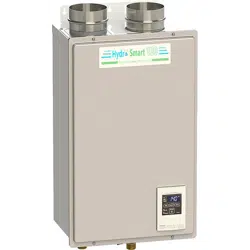
The Hydro Smart 120 Condensing Gas
Micro-Boiler is a compact and powerful
residential unit with a versatile BTU modulating
range.
Please refer to local codes for space-heating
compliance.
Models
• HS120CON-LP (Liquid propane)
• HS120CON-NG (Natural Gas)
ANSI Z21.10.3 and CSA 4.3
If the information in these
instructions is not followed
exactly, a re or explosion
may result causing property
damage, personal injury or
death.
WARNING
STOP
DO NOT return to stores. Damages or
repairs call Hydro Smart at 763-331-3066.
M-F: 8 AM - 5 PM SAT: 8 AM - 12 PM

Installation Manual
Page
2
Contents
CONTENTS
INSTALLATION MANUAL ........................................................................ 3
SPECIFICATIONS .................................................................................................4
INTRODUCTION ....................................................................................................5
SAFETY GUIDELINES ..........................................................................................6
INSTALLATION ......................................................................................................7
-GENERAL- .................................................................................................................7
-INCLUDED ACCESSORIES- .....................................................................................9
-CLEARANCES- ..........................................................................................................9
-VENTING INSTRUCTIONS- ....................................................................................10
-GAS SUPPLY AND GAS PIPE SIZING- ...................................................................20
-CONDENSATE DRAIN- ...........................................................................................26
-ELECTRICAL CONNECTIONS- ...............................................................................28
-HIGH-ALTITUDE INSTALLATIONS- .........................................................................29
-WATER CONNECTIONS- ........................................................................................30
APPLICATIONS ...................................................................................................31
-INITIAL OPERATION- ..............................................................................................33
OPTIONAL ITEMS ...............................................................................................34
OWNER'S GUIDE ................................................................................. 40
OPERATING SAFETY .........................................................................................41
NORMAL OPERATION ........................................................................................43
-DISPLAY OF THE CONTROLLER- ..........................................................................43
-GENERAL- ...............................................................................................................43
-TEMPERATURE TABLE OF THE CONTROLLER- ..................................................43
-TEMPERATURE SETTINGS- ..................................................................................44
-ADDITIONAL FEATURES- .......................................................................................45
-FLOW- ......................................................................................................................46
-FREEZE PROTECTION SYSTEM- ..........................................................................46
-MAINTENANCE AND SERVICE- .............................................................................47
-UNIT DRAINING- .....................................................................................................47
TROUBLESHOOTING .........................................................................................48
-GENERAL- ...............................................................................................................48
-ERROR CODES- ......................................................................................................49
COMPONENTS DIAGRAM ..................................................................................52
PARTS LIST .........................................................................................................56
OUTPUT TEMPERATURE CHART .....................................................................58
LIMITED WARRANTY ..........................................................................................59

Installation Manual
Page
3
CONGRATULATIONS
Installation Manual
Congratulations and thank you for choosing our condensing micro-boiler. Before use, we recommend
that you read through this safety manual carefully. Please refer to the back of the manual for details
about the warranty. Keep this manual for future reference.
If you lose the manual, contact the manufacturer or your local distributor. When you call, please tell us
the model number and the serial number of your unit written on the rating plate of the micro-boiler.
Installation Manual
Page
4
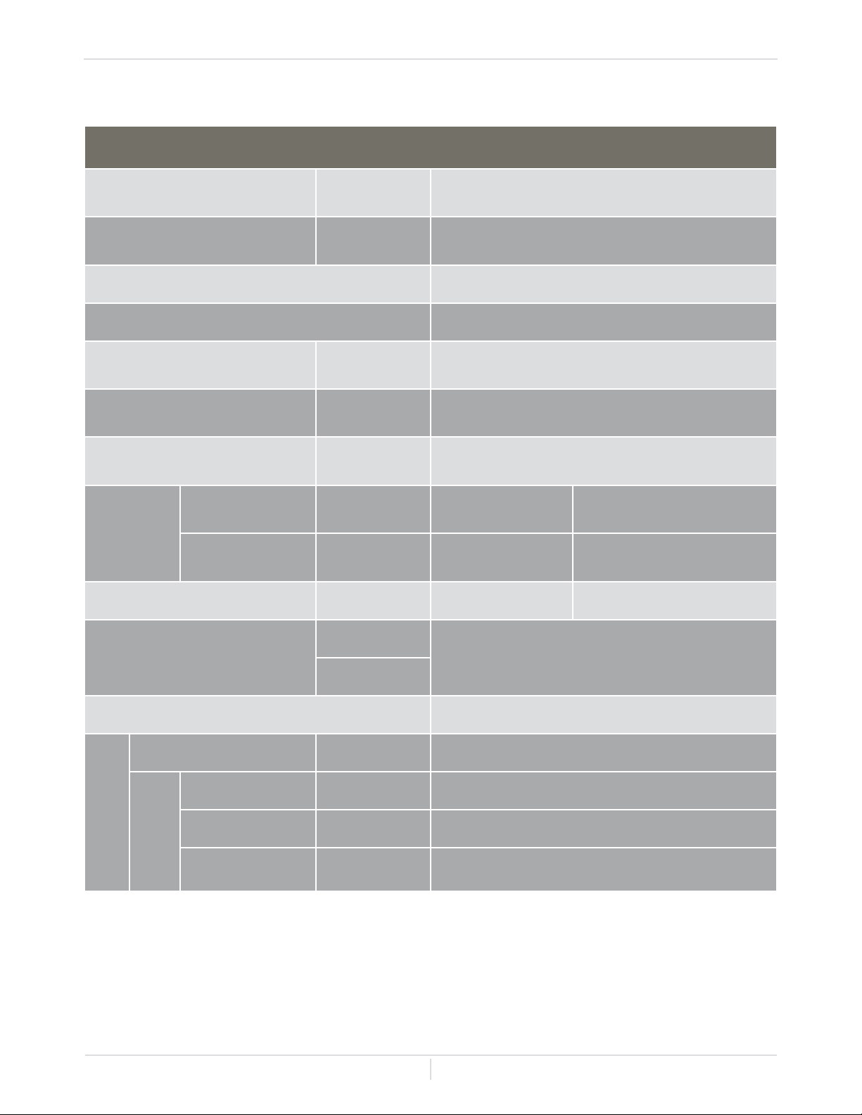
Specications
SPECIFICATIONS
* 40 psi (0.27 MPa) or above is recommended for maximum ow.
** The manifold pressure is the factory setting and should not need adjustment.
Note:
Check the rating plate to ensure this product matches your specications.
In accordance with ANSI Z21.10.3, CO emission does not exceed 400 PPM for normal input.
The manufacturer reserves the right to discontinue, or change at any time, specications or designs
without notice and without incurring obligation.
Hydro Smart Gas Condensing Micro-Boiler
Natural Gas Input
(Operating Range)
BTU/h
Min.: 15,000
Max.: 120,000
Propane Input
(Operating Range)
BTU/h
Min.: 15,000
Max.: 120,000
Gas Connection 1/2" NPT
Water Connection 3/4" NPT
Water Pressure*
psi
(MPa)
15 - 150 (0.1 - 1.0)
Natural gas
Inlet Pressure
inch W.C.
(kPa)
Min. 5.0 (1.2)
Max. 10.5 (2.6)
Propane
Inlet Pressure
inch W.C.
(kPa)
Min. 8.0 (2.0)
Max. 14.0 (3.5)
Manifold
Pressure
**
Natural
Gas
inch W.C.
(Pa)
3.30
(820)
2.00
(500)
Propane
inch W.C.
(Pa)
3.00
(750)
1.60
(400)
Weight lbs. (kg) 50 (22.5) 50 (22.5)
Dimension
inch
H 21-3/4 x W 14 x D 9-1/4
H 552 x W 352 x D 236
mm
Ignition Electric Ignition
Electric
Supply VAC / Hz 120 / 60
Consumption
Operation W / A 53.9 / 0.7
Standby W / A 3.2 / 0.05
Freeze-
Protection
W / A 223.9 / 1.94
Installation Manual
Page
5
• This manual provides information necessary for the installation,operation, and maintenance of the
micro-boiler.
• The model description is listed on the rating plate which is attached to the side panel of the micro-
boiler.
• Please read all installation instructions completely before installing this product.
• If you have any problems or questions regarding this equipment, consult the manufacturer or its
local representative.
• These hight efciency models have a built-in secondary heat exchanger that absorbs latent heat
from the exhaust gas.
• The Hydro Smart HS120 Condensing Gas Micro Boiler is only to be installed indoors.
• The principle behind condensing micro-boiler is simple:
INTRODUCTION
1. Your thermostat indicates a need for heat and turns on a circulator pump.
2. Fluid enters the heater.
3. The ow sensor detects the uid ow.
4. The computer initiates the fan motor and sends a signal to the igniter to create an ignition spark.
5. The gas ignites and ames appear within the burner chamber.
6. Fluid circulates through the heat exchanger and then gets hot.
7. Using thermistors to measure temperatures throughout the micro-boiler, the computer modulates
the gas and water valves to ensure proper output uid temperature.
8. Your room reaches desired temperature and the micro-boiler shuts off.
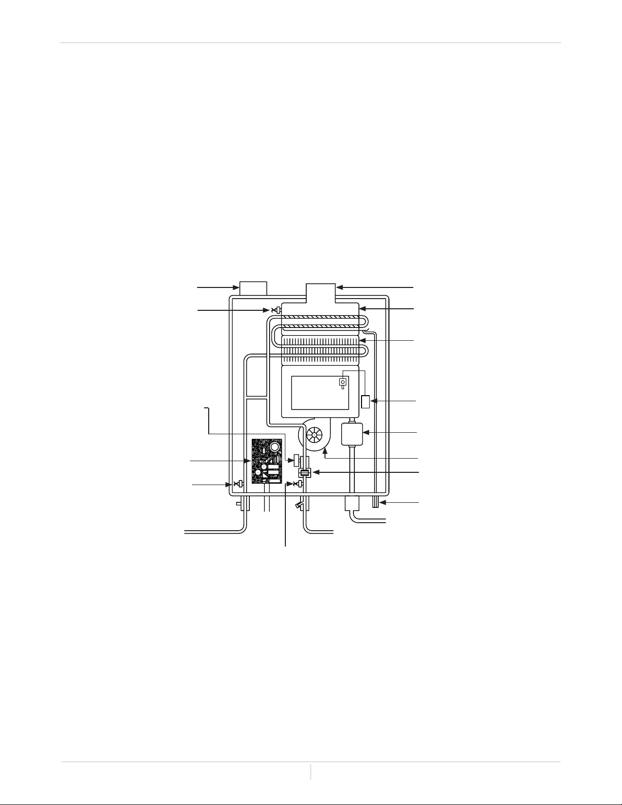
* This diagram illustrates condensing micro-boiler design concepts only and does not accurately
represent the micro-boiler's physical description.
Introduction
Burners
Exhaust
Secondary
heat exchanger
Primary
heat exchanger
Igniter
Gas valve
Fan motor
Flow sensor
Condensate
drain port
Gas inlet
Cold water inlet
Thermistor
Hot water outlet
Thermistor
Intake port
Exhaust
Thermistor
Water control
valve
Computer
board
Installation Manual
Page
6
SAFETY GUIDELINES
Indicates an imminently hazardous situation which, if not avoided, could re-
sult in minor or moderate injury.
1. Follow all local codes, or in the absence of local codes, follow the most recent edition of the
National Fuel Gas Code: ANSI Z223.1/NFPA 54 in the USA or CAN/CSA B149.1 Natural Gas,
Propane Installation Code in Canada.
2. Properly ground the micro-boiler in accordance with all local codes or in the absence of local
codes, with the National Electrical Codes: ANSI/NFPA 70 in the USA or CSA standard C22.1
Canada Electrical Code Part 1 in Canada.
3. Carefully plan where you intend to install the micro-boiler. Please ensure:
• Your micro-boiler will have enough combustible air and proper ventilation.
• Locate your boiler where uid leakage will not damage surrounding areas (refer to p. 8).
4. Check the rating plate for the correct GAS TYPE, GAS PRESSURE, FLUID PRESSURE and
ELECTRIC RATING.
*If this micro-boiler does not match your requirements, do not install and consult with the
manufacturer.
5. If any problem should occur, turn off all thermostats and turn off the gas. Then call a trained
technician or the Gas Company or the manufacturer.
Indicates an imminently hazardous situation which, if not avoided, could re-
sult in death or serious injury.
Indicates an imminently hazardous situation which, if not avoided, will result
in death or serious injury.
-Safety Denition-
-General-
• Do not store or use gasoline or other ammables, vapors, or liquids in the
vicinity of this appliance.
• Do not reverse the uid and/or gas connections as this will damage the
gas valves and can cause severe injury or death. Follow the diagram in
the Applications section on p. 31 when installing your micro-boiler.
• Do not use this micro-boiler if any part has been in contact with or been
immersed in water. Immediately call a licensed plumber, a licensed gas
tter, or a professional service technician to inspect and/or service the
micro-boiler if necessary.
• Do not disconnect the electrical supply if the ambient temperature will
drop below freezing. The Freeze Protection System only works if the
micro-boiler has electrical power. The heat exchanger will not be covered
under warranty if it is damaged due to freezing. Refer to "-FREEZE
PROTECTION SYSTEM-" on page 46 for more information.
Safety Guidelines
CAUTION
WARNING
WARNING
DANGER

Installation Manual
Page
7
1. Follow all local codes, or in the absence of local codes, follow the most recent edition of the
National Fuel Gas Code: ANSI Z223.1/NFPA 54 in the USA or CAN/CSA B149.1 Natural Gas,
Propane Installation Code in Canada.
2. All gas micro-boilers require careful and correct installation to ensure safe and efcient operation.
This manual must be followed exactly. Read the "Safety Guidelines" section.
3. The manifold gas pressure is preset at the factory. It is computer controlled and should not need
adjustment.
4. Maintain proper space for servicing. Install the micro-boiler so that it can be connected or removed
easily. Refer to the "Clearances" section on p. 9 for proper clearances.
5. The micro-boiler must be installed in a location where the proper amount of combustible air will be
available to it at all times without obstructions.
6. The electrical connection requires a means of disconnection, to terminate power to the micro-boiler
for servicing and safety purposes.
7. Do not install the micro-boiler where the exhaust vent is pointing into any opening in a building or
where the noise may disturb your neighbors. Make sure the vent termination meets the required
distance by local code from any doorway or opening to prevent exhaust from entering a building
(refer to the "-Vent termination clearances-" section beginning on page 17).
8. Particles from our, aerosols, clothes dryers and other airborne contaminants may clog the air
vent, build up and reduce the functions of the rotating fan, cause improper burning of the gas, or
cause damage to the micro-boiler. Regularly ensure that the area around the micro-boiler is dust-
or debris- free. Regular maintenance is recommended for these types of environments. Sealed
combustion is recommended too.
9. The Hydro Smart 120 micro-boiler is to be installed indoors only. The model is equipped with a
thermistor and hi-limit switch for the exhaust gas, detecting excess temperatures within the ue
and enabling the micro-boiler to safely stop operation if needed. These components are always
monitoring exhaust gas conditions in order to prevent heat damage to ABS, PVC, CPVC, or
Polypropylene (Plastic) venting if ABS, PVC, CPVC, or Polypropylene is used. If the exhaust gas
temperature exceeds 140°F (60°C) these components will enable the micro-boiler to safely stop
operation.
• The micro-boiler requires 3 inch, or 4 inch diameter intake air supply pipe. The intake pipe
must be sealed airtight.
• Air supply pipe can be made of aluminum exible tube, ABS, PVC, CPVC, Polypropylene,
corrugated stainless steel, or Category III/IV stainless steel. Regarding exhaust pipe, please
refer to p. 11 for detailed information.
• Sidewall venting is recommended for this boiler. Vertical venting (roof termination) is
acceptable.
• The manufacturer recommends running the exhaust vent and the intake pipe as parallel as
possible.
-General-
INSTALLATION
Installation

Installation Manual
Page
8
• Damage caused by water quality is not covered by the warranty.
• Only potable water or potable water / glycol mixtures can be used
with this micro-boiler. Do not introduce pool or spa water, or any
chemically treated water into the micro-boiler.
• Water hardness levels must not exceed 7 grains per gallon (120 ppm)
for single family domestic applications or more than 4 grains per
gallon (70 ppm) for all other types of applications. Water hardness
leads to scale formation and may affect / damage the micro-boiler.
Hard water scaling must be avoided or controlled by proper water
treatment. Distilled water is recommended.
• Water pH levels must be between 6.5 and 8.5
• Well water must be treated.
• Do not install the micro-boiler where water, debris, or ammable vapors
may get into the ue terminal.
• Although the micro-boiler is designed to operate with minimal sound, the
manufacturer does not recommend installing the micro-boiler on
a wall adjacent to a bedroom, or a room that is intended for quiet
study or meditation, etc.
• Locate your boiler close to a drain where water leakage will not do
damage to surrounding areas. As with any uid heating appliance, the
potential for leakage at some time in the life of a product does exist. The
manufacturer will not be responsible for any water damage that may
occur. If you install a drain pan under the micro-boiler, ensure that it will
not restrict the combustion air ow.
• Installation and service must be performed by a qualied installer (for
example, a licensed plumber or gas tter), otherwise the warranty will be
void.
• The installer (licensed professional) is responsible for the correct
installation of the micro-boiler and for compliance with all national, state /
provincial, and local codes.
• The manufacturer does not recommend installing the micro-boiler in a pit
or location where gas and water can accumulate.
• Do not have the vent terminal pointing toward any operating window,
door, or opening into a building.
• Do not install the micro-boiler next to any source of airborne debris, such
as a clothes dryer and a vent that can cause debris to be trapped inside
the combustion chamber, unless the system is direct-vented.
• The manufacturer does not recommend installing the micro-boiler in
an attic due to safety issues. If you install the micro-boiler in an attic:
• Make sure the micro-boiler will have enough combustion air and
proper ventilation.
• Keep the area around the micro-boiler clean. When dust collects on
the ame sensor, the micro-boiler will shut down on an error code.
• Place the micro-boiler in a location that provides easy access for
service and maintenance.
• A drain pan, or other means of protection against water damage, is
required to be installed under the micro-boiler in case of leaks.
• It is recommended to direct vent the heater.
Installation
CAUTION
WARNING
Installation Manual
Page
9
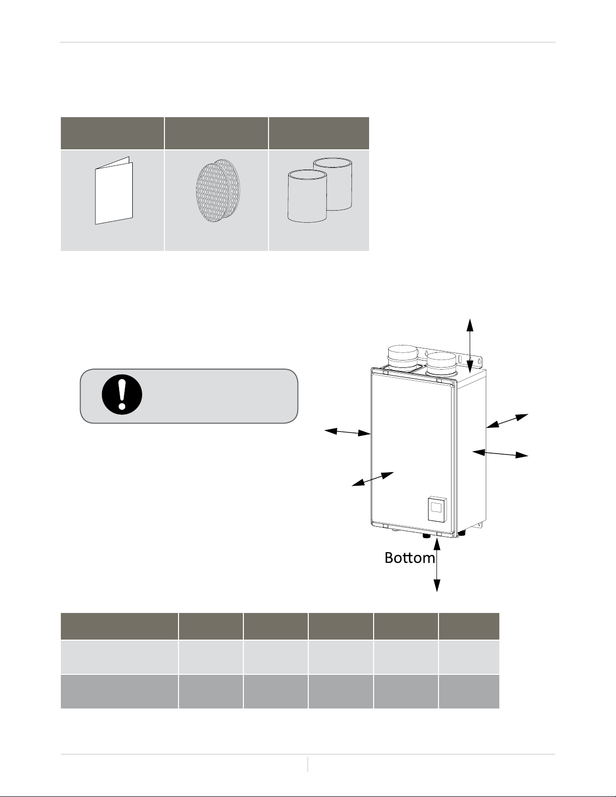
Maintain all clearances
around the micro-boiler.
-CLEARANCES-
Check that these items below are included with the micro-boiler.
* For more information on optional items, please refer to "OPTIONAL ITEMS" section beginning on
page 34
Installation Manual
and Owner's Guide
Bird Screen PVC Couplers
Model Top Bottom Front Back Sides
HS120Con-LP
(Liquid propane)
12 in.
(305 mm)
12 in.
(305 mm)
4 in. *
(120 mm)
1 in.
(25 mm)
3 in.
(76 mm)
HS120Con-NG
(Natural gas)
12 in.
(305 mm)
12 in.
(305 mm)
4 in. *
(120 mm)
1 in.
(25 mm)
3 in.
(76 mm)
* 24 inches recommended for maintenance
Installation
-INCLUDED ACCESSORIES-
Qty. 1 Qty. 2 Qty. 2
Top
Back
Side
Side
Front
Installation Manual
Page
10
-VENTING INSTRUCTIONS-
-GENERAL-
When installing the vent system, all applicable national and local codes must
be followed. If you install thimbles, re stops or other protective devices and
they penetrate any combustible or noncombustible construction, be sure to
follow all applicable national and local codes.
• Improper venting of this appliance can result in excessive levels of carbon
monoxide which can result in severe personal injury or death.
• Improper installation can cause nausea or asphyxiation, severe injury
or death from carbon monoxide and ue gases poisoning. Improper
installation will void product warranty.
The micro-boiler must be vented in accordance with the section "Venting of Equipment" of the latest
edition of the National Fuel Gas Code: ANSI Z223.1/NFPA 54 in the United States and/or Section 7
of the CAN/CSA B149.1 Natural Gas and Propane Installation Code in Canada, as well as applicable
local building codes.
The use of venting materials approved for Category III/IV appliances is recommended whenever
possible. However, the micro-boiler may also be vented with plastic pipe materials such as ABS,
PVC, CPVC, or Polypropylene. For details, please refer to the Exhaust Vent (ABS, PVC, CPVC,
or Polypropylene Vent) section on p. 11. Vent installations in Canada which utilize plastic vent
systems must use venting that complies with ULC S636.
• Place the micro-boiler as close as possible to the vent termination.
• The vent collar of the micro-boiler must be fastened directly to an unobstructed vent pipe.
• Do not weld the vent pipe to the micro-boiler's vent collar.
• Do not cut or alter the vent collar of the micro-boiler.
• The vent must be easily removable from the top of the micro-boiler for normal service and
inspection of the unit.
• Avoid using an oversized vent pipe or using extremely long runs of the pipe.
• For rooftop venting, a rain cap or other form of termination that prevents rain water from
entering into the micro-boiler must be installed.
• Do not terminate the vent into a chimney. If the vent must go through the chimney, the vent
must run all the way through the chimney with approved vent pipe.
General rules for venting micro-boiler are:
• Avoid locating the micro-boiler vent termination near any air intake devices. These fans can
pick up the exhaust ue products from the micro-boiler and return them to the building. This
can create a health hazard.
• Locate the vent termination so that it cannot be blocked by any debris, at any time. Most
codes require that the termination be at least 12 inches (305mm) above grade, but the installer
may determine if it should be higher depending on the job site condition and applicable codes.
• A proper sidewall termination is recommended when the micro-boiler is vented through a
sidewall.
• Regarding the clearances from the exhaust termination to the air inlet or opening, refer to the
"-Vent termination clearances-" section beginning on page 17.
General rules for vent terminations:
Installation - Venting
For the Hydro Smart HS120 Gas Condensing Micro Boiler
CAUTION
DANGER

Installation Manual
Page
11
-Exhaust vent (ABS, PVC, CPVC, or Polypropylene vent)-
The micro-boiler can be vented with ABS, PVC, CPVC, or Polypropylene (temperature rated up to at
least 149° F). Vent material certied to ULC S636 standards is recommended in the USA. In Canada,
plastic venting must be certied to ULC S636 standards.
• The maximum length of exhaust vent piping must not exceed 70 ft. (21.3 m) for 3" venting,
which depends on the elevation where the micro-boiler is installed, and 100 ft. (30.5 m) for 4"
venting (deducting 5 ft. (1.5 m) for each elbow used in the venting system). Do not use more
than 5 elbows. See the table below.
• When the horizontal vent run exceeds 5 ft. (1.5 m), support the vent run at 3 ft. (0.9 m)
intervals with overhead hangers.
-Max. Vertical or Horizontal (total) Vent Length-
Item Material United States Canada
Exhaust pipe and
Fittings
Schedule 40 PVC ANSI/ASTM D1785
ULC S636 Certied
Materials Only
PVC-DWV ANSI/ASTM D2665
Schedule 40 CPVC ANSI/ASTM F441
Schedule 40 ABS-
DWV
ANSI/ASTM D2661
Polypropylene UL-1738
Pipe Cement / Primer
PVC ANSI/ASTM D2564
CPVC ANSI/ASTM F493
ABS ANSI/ASTM D2235
Note: Do NOT Use Cellular Foam Core Pipe
No. of
Elbow
2" venting 3" venting 4" venting
Up to 3,000 ft Up to 3,000 ft Up to 6,000 ft Up to 10,100 ft Up to 10,100 ft
0 6.5 ft. (2.0 m) 70 ft. (21.3 m) 40 ft. (12.2 m) 25 ft. (7.6 m) 100 ft. (30.5 m)
1 1.5 ft. (0.5 m) 65 ft. (19.8 m) 35 ft. (10.7 m) 20 ft. (6.1 m) 95 ft. (29.0 m)
2 N/A 60 ft. (18.3 m) 30 ft. (9.1 m) 15 ft. (4.6 m) 90 ft. (27.4 m)
3 N/A 55 ft. (16.8 m) 25 ft. (7.6 m) 10 ft. (3.0 m) 85 ft. (25.9 m)
4 N/A 50 ft. (15.2 m) 20 ft. (6.1 m) 5 ft. (1.5 m) 80 ft. (24.4 m)
5 N/A 45 ft. (13.7 m) N/A N/A 75 ft. (22.9 m)
- Excludes vent terminators, termination elbows, or rain caps.
- For details on the vent connection, refer to the "-Intake and Exhaust Venting Illustrations-"
section beginning on page 13.
* For each elbow added, deduct 5 ft. (1.5 m) from max. vent length.
Installation - Venting
Installation Manual
Page
12
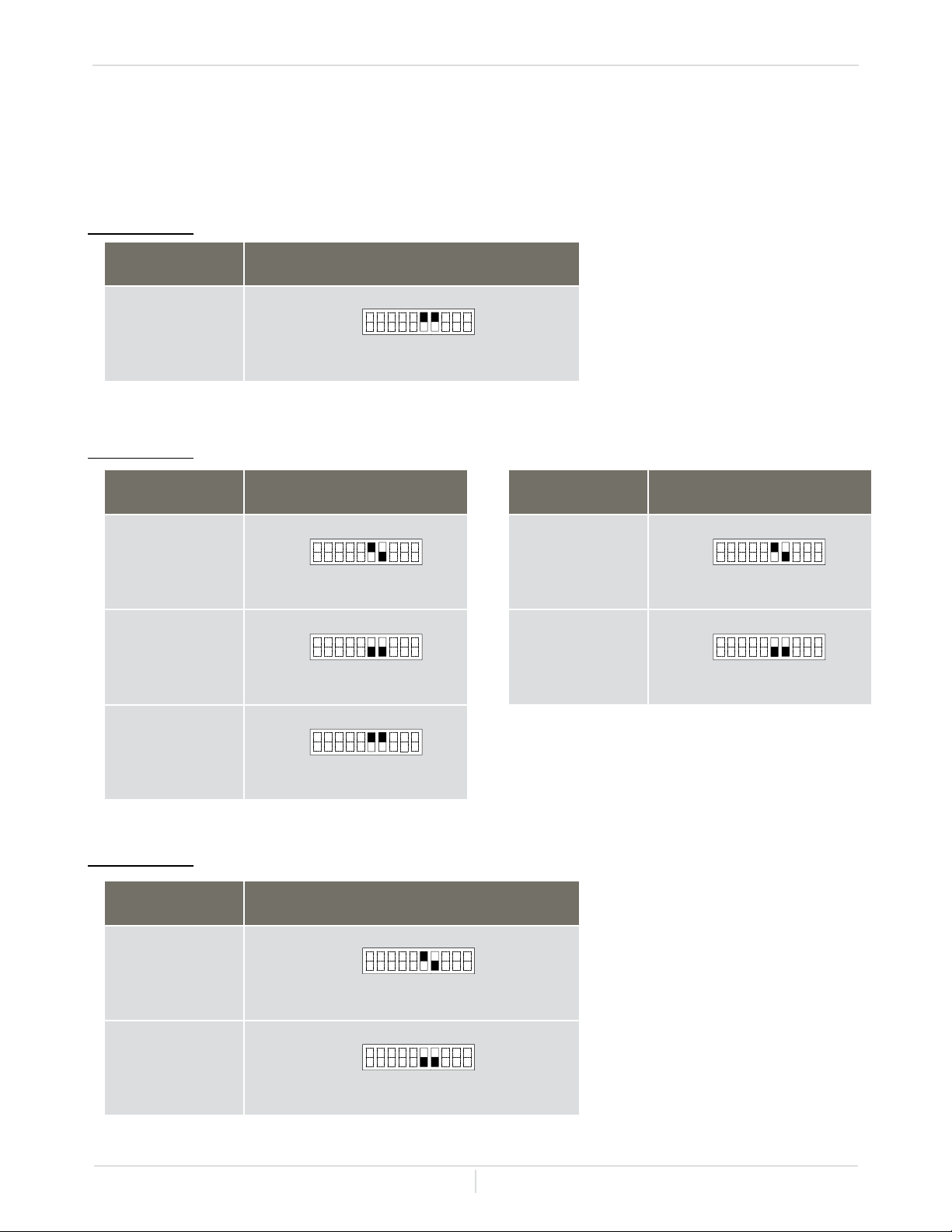
-GENERAL-
Set DIPswitches shown in the tables below depending on the vent length. Only adjust switches with a
black square. Black squares indicate the position of the switch.
2 inch venting
3 inch venting
4 inch venting
Vent length Single pipe
5 to 6.5 ft.
Vent length Two-pipe
5 to 20 ft.
(DEFAULT)
21 to 40 ft.
41 to 70 ft.
Vent length Single pipe
5 to 45 ft.
(DEFAULT)
46 to 70 ft.
Vent length Two-pipe and Single pipe
5 to 50 ft.
(DEFAULT)
51 to 100 ft.
Installation - Venting
1 2 3 4 5 6 7 8 9 10
No. 6 : ON
No. 7 : ON
OFF
ON
1 2 3 4 5 6 7 8 9 10
No. 6 : ON
No. 7 : OFF
OFF
ON
1 2 3 4 5 6 7 8 9 10
No. 6 : OFF
No. 7 : OFF
OFF
ON
1 2 3 4 5 6 7 8 9 10
No. 6 : ON
No. 7 : OFF
OFF
ON
1 2 3 4 5 6 7 8 9 10
No. 6 : OFF
No. 7 : OFF
OFF
ON
1 2 3 4 5 6 7 8 9 10
No. 6 : ON
No. 7 : ON
OFF
ON
1 2 3 4 5 6 7 8 9 10
No. 6 : ON
No. 7 : OFF
OFF
ON
1 2 3 4 5 6 7 8 9 10
No. 6 : OFF
No. 7 : OFF
OFF
ON
Installation Manual
Page
13
Installation - Venting
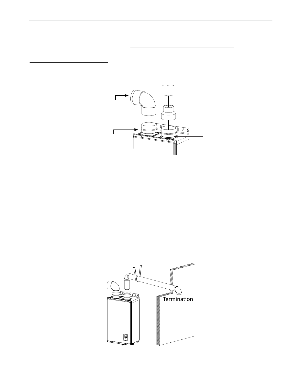
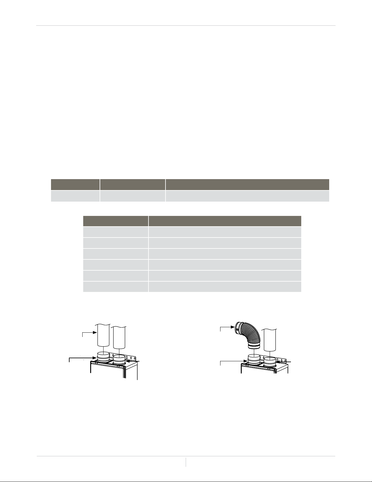
-Intake and Exhaust Venting Illustrations-
2 inch venting installation
Typical installations using ABS, PVC, CPVC, or Polypropylene vent
Vent connections for single pipe
Single pipe with room-air intake
For details of the optional items, refer to "OPTIONAL ITEMS" section beginning on page 34.
Refer to "-Vent termination clearances-" section beginning on page 17 for
clearance information
1. Connect a 3" elbow directly on the intake vent collar of
the micro-boiler.
2. Connect a 3" x 2" reducer directly on the exhaust vent
collar of the micro-boiler. Make sure the couplings
engage the o-rings installed in the intake and exhaust
vent collars.
3. Connect a 2" straight pipe to the reducer.
* The micro-boiler came with a metal screen that
will t into a 3 inch elbow.
Hanger
* 3" elbow with bird
screen
Intake vent
collar
(Female)
3"x2" reducer
2" straight pipe
Exhaust vent
collar (Female)
Installation Manual
Page
14
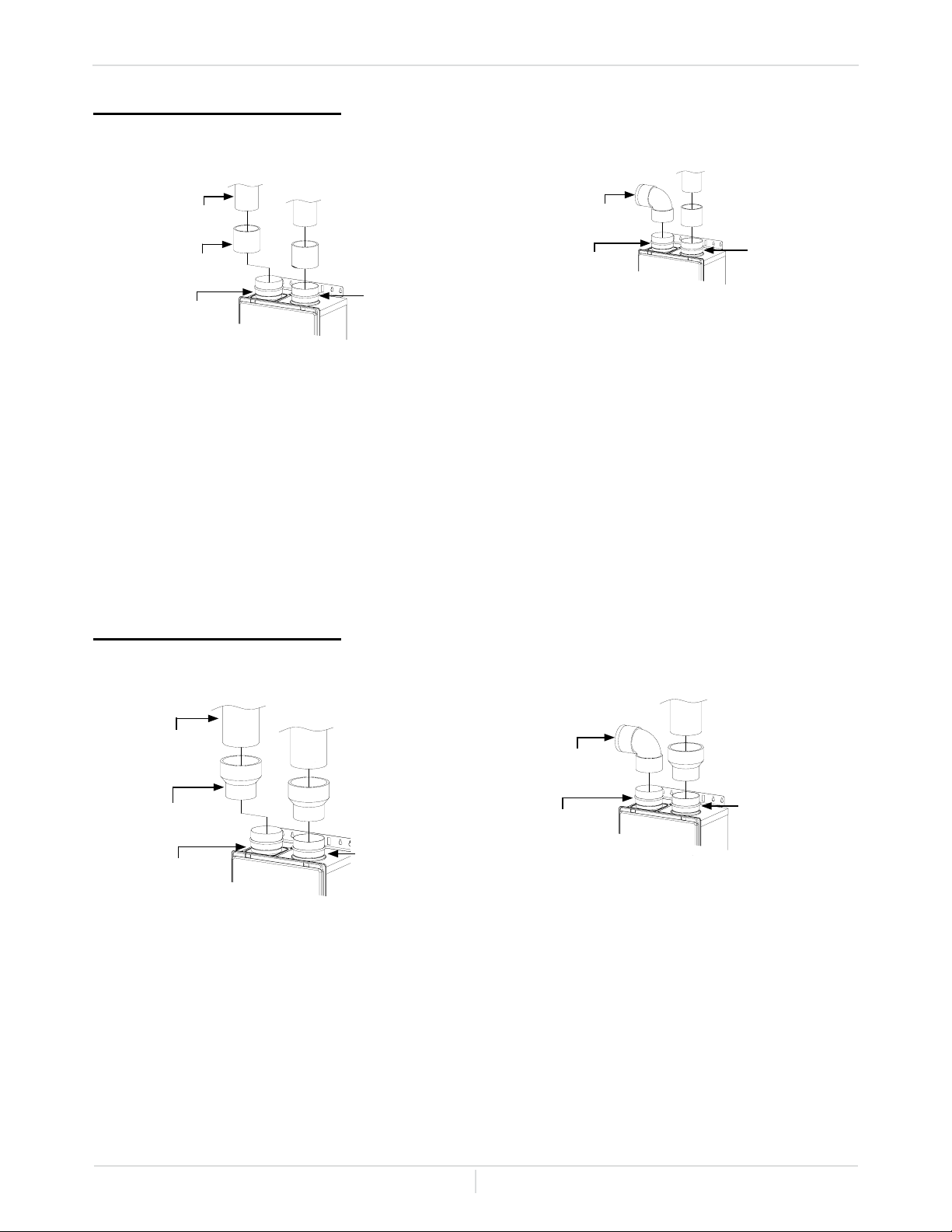
Installation - Venting
3 inch venting installation
Vent connections for two-pipe
For details of the optional items, refer to "OPTIONAL ITEMS" on page 34.
1. Connect 3" couplings directly on the
exhaust and intake vent collar of the
micro-boiler. Make sure the couplings
engage the o-rings installed in the intake
and exhaust vent collars.
2. Connect 3" straight pipes to the
couplings.
1. Connect a 3" elbow directly on the
intake vent collar of the micro-boiler.
2. Connect a 3" coupling directly on the
exhaust vent collar of the micro-boiler.
Make sure the couplings engage the
o-rings installed in the intake and
exhaust vent collars.
3. Connect a 3" straight pipe to the
coupling.
Vent connections for single pipe
4 inch venting installation
Vent connections for two-pipe
For details of the optional items, refer to "OPTIONAL ITEMS" on page 34.
1. Connect 3" x 4" increasers directly on
the exhaust and intake vent collar of the
micro-boiler. Make sure the couplings
engage the o-rings installed in the intake
and exhaust vent collars.
2. Connect 4" straight pipes to the
increasers.
1. Connect a 3" elbow directly on the
intake vent collar of the micro-boiler.
2. Connect a 3" x 4" increaser directly on
the exhaust vent collar of the micro-
boiler. Make sure the couplings engage
the o-rings installed in the intake and
exhaust vent collars.
3. Connect a 4" straight pipe to the
increaser.
Vent connections for single pipe
* The micro-boiler came with a metal
screen that will t into a 3 inch elbow.
* The micro-boiler came with a metal
screen that will t into a 3 inch elbow.
3"coupling
Exhaust
vent collar
(Female)
3" straight pipe
3" coupling
Intake vent
collar
(Female)
3" straight pipe
3" coupling
3" straight pipe
Exhaust
vent collar
(Female)
* 3" elbow with
bird screen
Intake vent
collar
(Female)
4" straight
pipe
3"x4" increaser
Exhaust
vent
collar
(Female)
Intake vent
collar
(Female)
4" straight
pipe
3"x4"
increaser
4" straight pipe
3"x4" increaser
Exhaust vent
collar (Female)
* 3" elbow with
bird screen
Intake vent
collar
(Female)
Installation Manual
Page
15
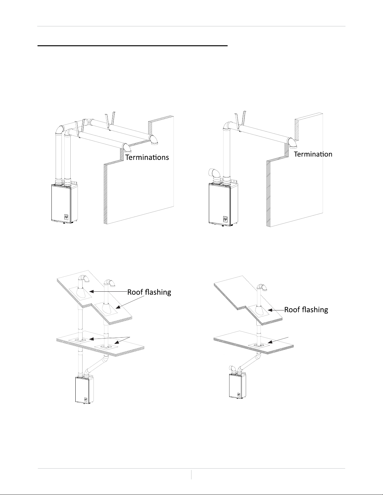
Installation - Venting
Examples of installation of 3 inch and 4 inch vent
Two-pipe, direct-vent
Single pipe with room-air intake
Refer to "-Vent termination clearances-" section beginning on page 17 for
clearance information
Wall
Hanger
Hanger
Roof
Fire stop
Fire stop
Roof
Wall
Hanger
Installation Manual
Page
16
Installation - Venting
-Exhaust vent (Stainless steel vent)-
This is a Category IV appliance and must be vented accordingly. The vent system must be sealed
airtight. All seams and joints without gaskets must be sealed with high heat resistant silicone sealant
or UL listed aluminum adhesive tape having a minimum temperature rating of 160° F. For best results,
a vent system should be as short and straight as possible.
• The micro-boiler is a Category IV appliance and must be vented accordingly with any 4 inch
vent approved for use with Category III / IV or Special BH type gas vent.
• The manufacturer recommends the NovaVent (Z-Vent) line. However, the following are also
UL listed manufacturers: ProTech Systems Inc. (FasNSeal), Metal-Fab Inc., and Heat-Fab Inc.
(Saf-T Vent).
• Follow the vent pipe manufacturer's instructions when installing the vent pipe.
• The maximum length of exhaust vent piping must not exceed 100 ft. (30.5 m) (deducting 5 ft.
(1.5 m) for each elbow used in the venting system). Do not use more than 5 elbows.
• When the horizontal vent run exceeds 5 ft. (1.5 m), support the vent run at 3 ft. (0.9 m)
intervals with overhead hangers.
Vent connections for two-pipe
1. Connect 4" stainless steel vent straight
pipes directly on the exhaust / intake
vent collar of the micro-boiler.
1. Connect a 4" stainless steel vent straight
pipes directly on the exhaust vent collar
of the micro-boiler.
2. Connect a 4" elbow directly on the
intake vent collar of the micro-boiler.
Vent connections for single pipe
No. of Elbows Max. Vertical or Horizontal Vent Length
0 100 ft. (30.5 m)
1 95 ft. (29.0 m)
2 90 ft. (27.4 m)
3 85 ft. (25.9 m)
4 80 ft. (24.4 m)
5 75 ft. (22.9 m)
Excludes vent terminators, termination elbows, or rain caps.
Diameter Max. No. of Elbows Max. Vertical or Horizontal (Total) Vent Length
4 in. (102 mm) 5 100 ft. (30.5 m)
* For each elbow added, deduct 5 ft. (1.5 m) from max. vent length.
4" stainless
steel vent
straight pipe
Exhaust vent
collar (Female)
Intake vent collar
(Female)
4" stainless
steel vent
straight pipe
Exhaust vent
collar (Female)
4" stainless
steel vent
straight pipe
Intake vent
collar
(Female)
4" elbow
with bird
screen
Installation Manual
Page
17
Installation - Venting
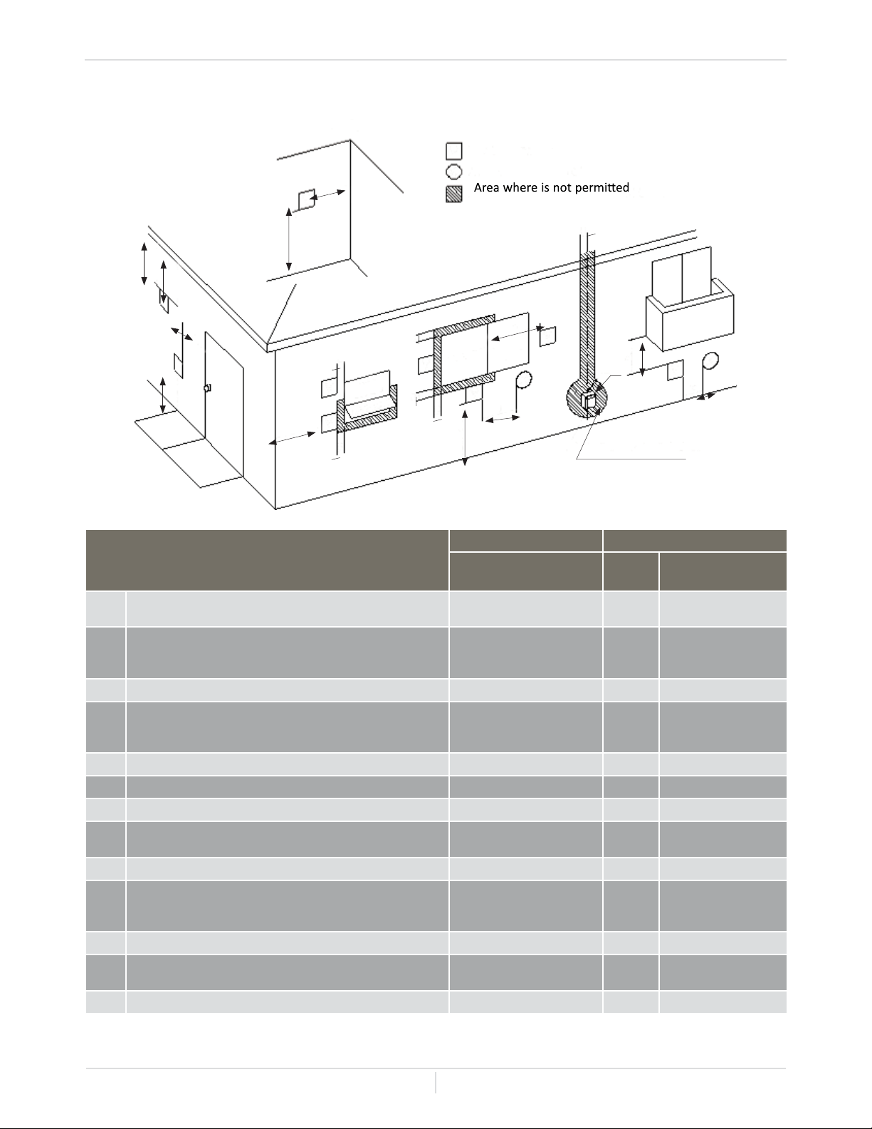
-Vent termination clearances-
* For clearances not specied in ANSI Z223.1/NFPA 54 or CAN/CSA-B149.1, please use clear-
ances in accordance with local installation codes and the requirements of the gas supplier.
Canada U.S.A
Direct-vent and other
than Direct-vent
Direct
- Vent
Other than
Direct -Vent
A
Clearance above grade, veranda, porch, deck, or
balcony.
1 foot 1 foot 1 foot
B
Clearance to window or door that may be opened 3 foot 1 foot
4 feet from below or
side opening. 1 foot
from above opening
C
Clearance to permanently closed window * * *
D
Vertical clearance to ventilated soft located above the
vent terminator within a horizontal distance of 2 feet
(61 cm) from the center line of the terminator
* * *
E
Clearance to unventilated soft * * *
F
Clearance to outside corner * * *
G
Clearance to inside corner * * *
H
Clearance to each side of center line extended above
meter/regulator assembly
3 feet * *
I
Clearance to service regulator vent outlet 3 feet * *
J
Clearance to non-mechanical air supply inlet to build-
ing or the combustion air inlet to any other application
3 feet 1 foot
4 feet from below or
side opening. 1 foot
from above opening
K
Clearance to mechanical air supply inlet 6 feet 3 feet 3 feet
L
Clearance above paved sidewalk or paved driveway
located on public property
7 feet * 7 feet
M
Clearance under veranda, porch deck, or balcony 1 foot * *
INSIDE CORNER DETAIL
V
Gas meter / regulator
V
V
V
V
V
V
V
V
V
X
X
X
Vent terminal
Air supply inlet
G
A
E
D
B
L
C
F
B
B
B
B
A
J
O
PERABLE
FIXED
CLO
SED
B
H
M
K
O
PERABLE
FIXED
CLO
SED
I
Installation Manual
Page
18
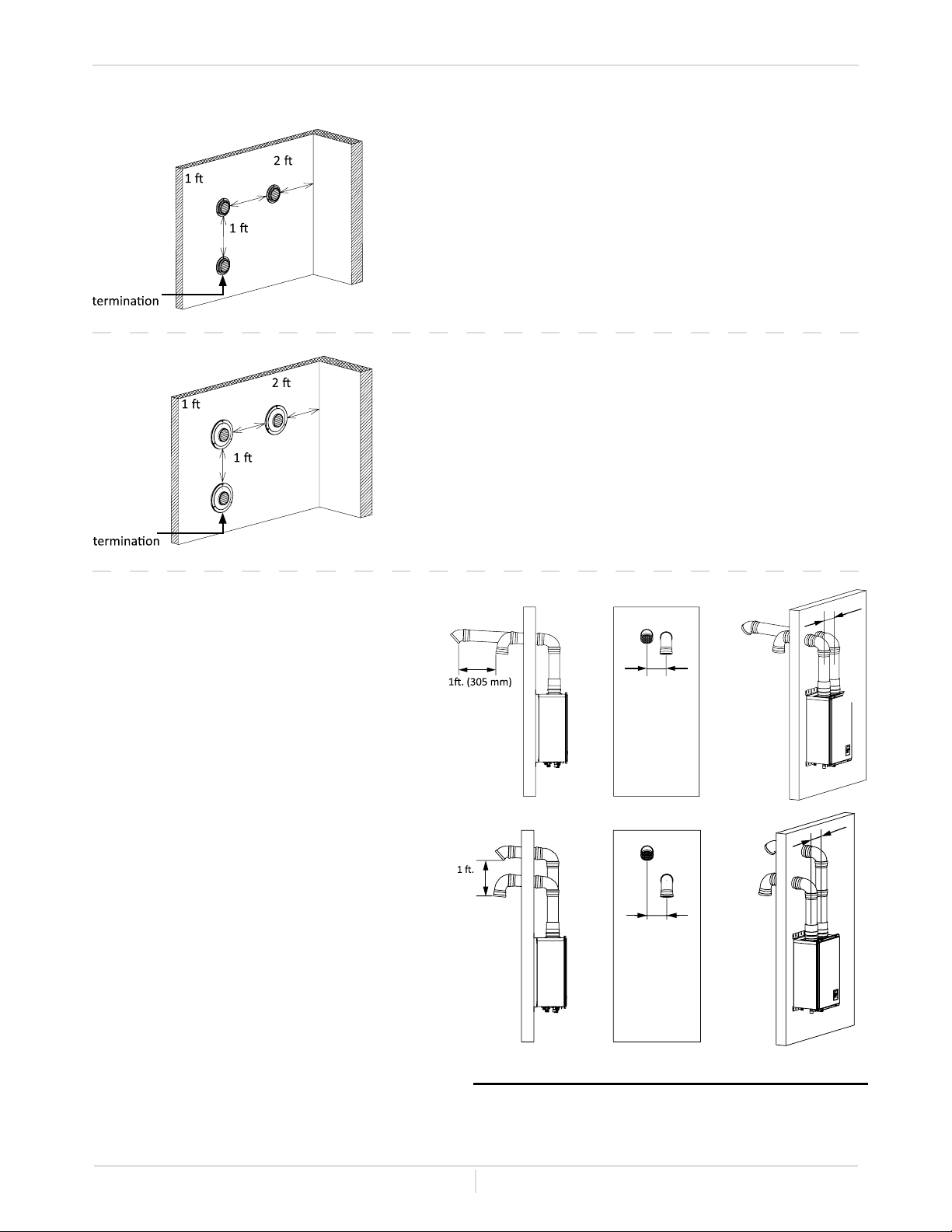
Installation - Venting
For multiple sidewall exhaust terminations, an exhaust
termination must be at least 1 ft. (305 mm) away from
another exhaust termination. An exhaust termination
must also be at least 2 ft. (610 mm) away from an inside
corner. (If the adjacent wall is less than 2 ft. (610 mm)
of length, the minimum required distance away from the
inside corner will be equal to the length of that adjacent
wall.)
For multiple, direct-vent sidewall terminations that
combine the intake and exhaust into a single penetration,
space each direct-vent termination at least 1 ft. (305 mm)
away from each other, no matter the orientation. A direct-
vent termination must also be a least 2 ft. (610 mm) away
from an inside corner. (If the adjacent wall is less than
2 ft. (610 mm) of length, the minimum required distance
away from the inside corner will be equal to the length of
the adjacent wall.
A: 0.5ft. (159 mm)
The clearance of A is recommended on the basis of the structure of the micro-boiler.
* 3 inch and 4 inch vent installations only
For direct-vent sidewall terminations
that use two separate penetrations
for the intake and exhaust, keep the
termination clearances shown in the
diagrams on the right.
Exhaust
Inside
corner
.
(305 mm) min.
.
(610 mm) min.
. (305 mm)
min.
Combined
intake and
exhaust
Inside
corner
.
(305 mm) min.
.
(610 mm) min.
. (305 mm)
min.
Exhaust
Intake
min.
Exhaust
Intake
A
A
Exhaust
Intake
(305 mm)
min.
Exhaust
Intake
A
A
-Case 1-
-Case 2-
Installation Manual
Page
19
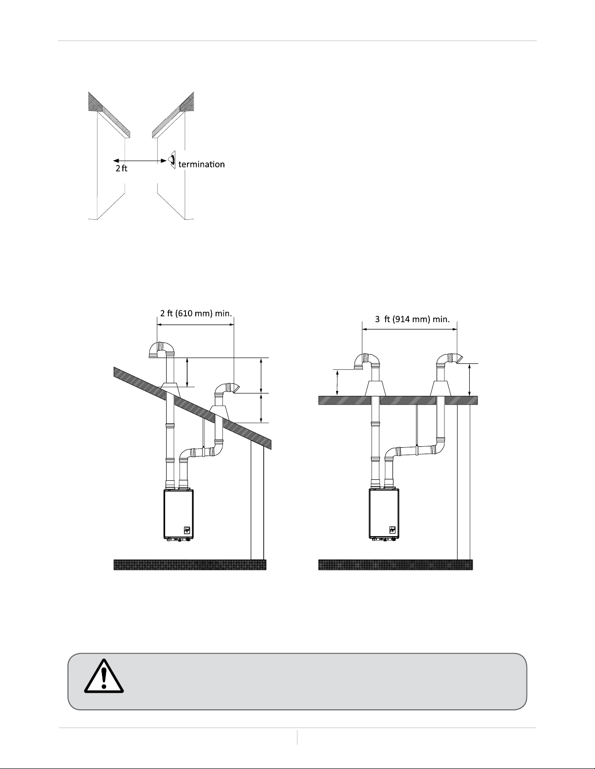
Installation - Venting
Exhaust and/or direct-vent sidewall terminations should
be at least 2 ft. (610 mm) away from an opposite surface
/ wall. Do not place the termination directly in front of an
opening into a building.
A: Exhaust terminations must be at least 1 ft. (305 mm) away from any obstructions.
B: Intake terminations must be at least 1 ft. (305 mm) away from any obstructions.
Please follow all local and national codes in regards to proper termination
clearances. In the absence of such codes, the clearances above can be used
as guidelines. Local codes supersede these guidelines.
-For rooftop terminations-
Exhaust
.(610 mm)
min
Intake air
B
B
A
Exhaust
Gas
Intake air
Exhaust gas
B
A
CAUTION
Installation Manual
Page
20
-GAS SUPPLY AND GAS PIPE SIZING-
• Check that the type of gas matches the rating plate rst.
• Ensure that any and all gas regulators used are operating properly and
providing gas pressures within the specied range shown below. Excess
gas inlet pressure may cause serious accidents.
• Conversion of this micro-boiler from natural to propane of vice versa will
void all warranty. Contact your local distributor to get the correct unit for
your gas type. The manufacturer is not liable for any property and/or per-
sonal damage resulting from gas conversion.
• INSTALLATION OF THIS GAS BOILER IS ONLY TO BE PERFORMED
BY A LICENSED PROFESSIONAL.
-General-
-Regulators-
The gas pressure delivered to this unit and other gas appliances needs to be constant and at the
correct pressure. Regardless of what type of gas you have, the supply gas pressure can change.
Depending on temperature LP (Liquid Propane) gas pressure inside a storage tank may be as low as
10psi in the cold of winter or as high as 200psi in the heat of summer. NG (Natural Gas) gas pressures
can also very greatly depending on the geographic region, season, time of day and other reasons. The
gas regulator must keep gas owing to the boiler at a constant pressure even as the gas supply (LP
storage tanks or NG gas mains) and the number of appliances consuming gas changes (as devices
turn on and off in the home).
• The minimum and maximum inlet gas pressures are:
• Inlet gas pressures that fall outside the range of values listed above may adversely affect the per-
formance of the micro-boiler. These pressures are measured when the micro-boiler is in full opera-
tion.
• Inlet gas pressure must not exceed the above maximum values; gas pressure above the specied
range will cause dangerous operating conditions and damage to the micro-boiler.
Gas type Inlet gas pressures
Natural Gas Min. 5.0” W.C. (1.24 kPa) - Max. 10.5” W.C. (2.61 kPa)
Propane Min. 8.0” W.C. (1.99 kPa) - Max. 14” W.C. (3.48 kPa)
Installation - Gas
CAUTION
Installation Manual
Page
21
-Regulator Installation Example (Natural Gas)-
1. Gas Appliance Shutoff
- required to shutoff the gas supply to the boiler if the need for service
or repair arises.
2. Drip Leg - a plumbing conguration that is used to remove debris from the gas line before it
enters the boiler. A drip leg consists of a black iron T tting, a straight Black iron pipe (about 3-4”)
and a cap.
3. Flexible Gas Line - the regulator should be a minimum of 3’ from the boiler. The exible gas line
is an ideal solution, it reduces space and helps with alignment.
4. Regulator - needed to deliver constant pressure to the boiler. The NG supply after the meter is
about 2 psi and needs to be reduced to 5.0 - 10.5” W.C. (1.24 - 2.61 kPa) for the micro-boiler.
5. Gas Company Meter and Regulator
6. Incoming Gas Supply from utility company.
Installation - Gas
5
6
4
3
2
1
Installation Manual
Page
22
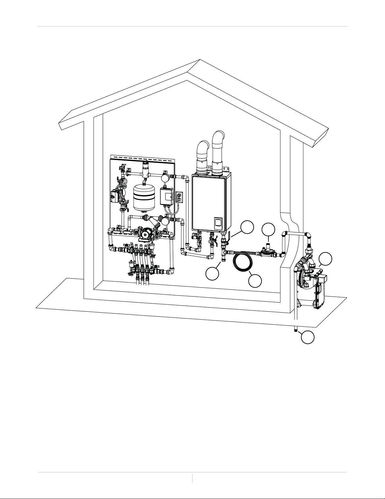
-Regulator Installation Example (Liquid Propane)-
1. Gas Appliance Shutoff - required to shutoff the gas supply to the boiler if the need for service
or repair arises.
2. Drip Leg - a plumbing conguration that is used to remove debris from the gas line before it
enters the boiler. A drip leg consists of a black iron T tting, a straight Black iron pipe (about 3-4”)
and a cap.
3. Flexible Gas Line - the regulator should be a minimum of 3’ from the boiler. The exible gas line
is an ideal solution, it reduces space and helps with alignment.
4. Line/Appliance Regulator - needed to deliver the precise gas pressure the micro-boiler needs.
It will drop the second stage regulator's 2 psi pressure down to inches of W.C.
5. Second stage regulator - brings gas pressure down to either 2 psi. or inches of W.C. The
micro-boiler operates on inches of W.C.(See Specs)
6. Propane Tank - gas pressures varies between 10 psi and 200 psi.
7. First stage regulator - brings tank gas pressure down to 10 psi. output, to high for the boiler.
8. Safety relief valve - relieves pressure in case the tank pressure build past the design
parameters.
9. Tank shutoff Valve - this valve will shut the supply to the whole house / system off.
10. Fuel Gauge - indicates the level of fuel in the tank.
Installation - Gas
5
4
3
2
1
6
7
8
10
9
Installation Manual
Page
23
Size the gas pipe appropriately to supply the necessary volume of gas
required for the micro-boiler using ANSI Z223.1/NFPA 54 in the USA or CAN/
CSA B149.1 in Canada or local codes. Otherwise, ow capabilities and
output temperatures will be limited.
This unit is not equipped with a regulator. A gas regulator is required for all
gas appliance installations.
You should always check and follow local codes and regulations. THIS IS
ONLY TO BE INSTALLED BY A LICENSED PROFESSIONAL.
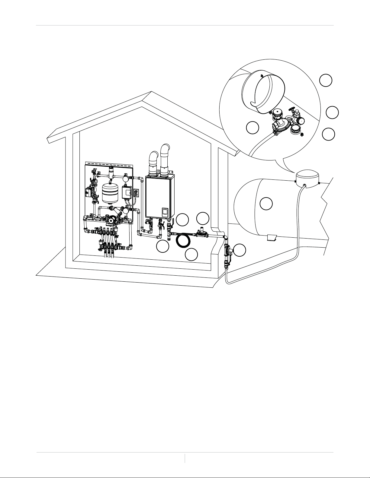
-Gas Connections-
1. Install a manual gas shutoff valve, drip leg, exible gas line and regulator between the micro-boiler
and the gas supply line as pictured. The gas supply line shall be checked for leaks using code
approved methods.
2. When the gas connections are completed, it is necessary to perform a gas leak test either by
applying soapy water to all gas ttings and observing for bubbles or by using a gas leak detection
device.
• The micro-boiler and its individual shutoff valve must be disconnected from the gas supply
piping system during any pressure testing of that system at test pressures in excess of 1/2 psi
(3.5 kPa).
• The micro-boiler must be isolated from the gas supply piping system by closing its individual
manual shutoff valve during any pressure testing of the gas supply piping system at test
pressures equal to or less than 1/2 psi (3.5 kPa).
3. Always purge the gas line of any debris and/or water before connecting to the gas inlet.
NOTICE
Installation - Gas
Owner's Guide
Page
24
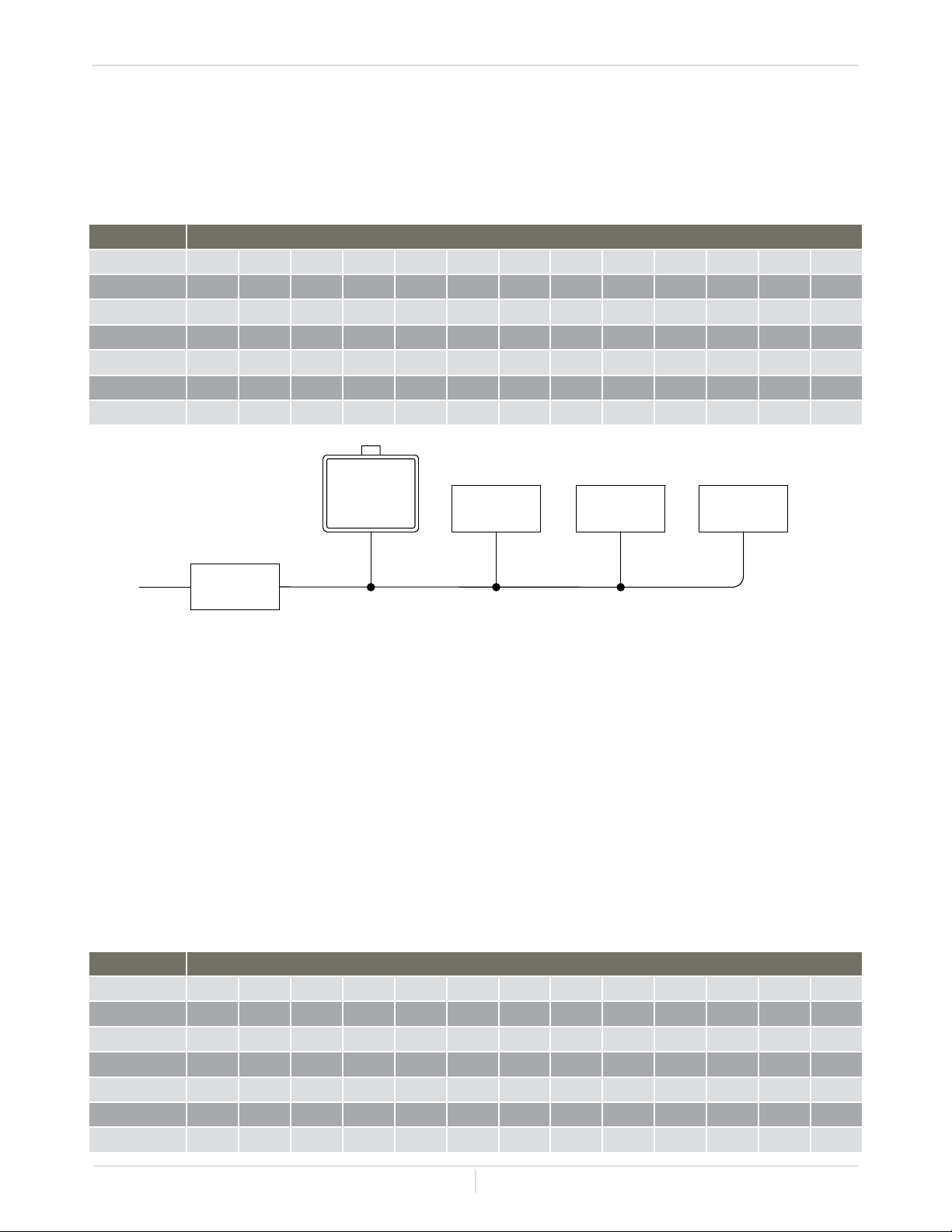
-Natural Gas (NG) Supply Piping-
For example: The section from A to B supplies gas to the furnace, range and dryer. Adding up the BTU
requirements and dividing by 1,000 yields a cubic ft. requirement of 220 cubic ft. of gas. The farthest
appliance is the range, which is 50 ft. away from the meter. Looking at the above chart, and under the
column of 50 ft., section A to B needs to be 1” in order to supply 220 cubic ft.
Based on energy content of 1,000 BTU/Cubic ft.: The micro-boiler requires 120 Cubic ft./hr
Based on energy content of 1,000 BTU/Cubic ft:
Maximum delivery capacity of cubic feet of gas per hour of IPS Pipe carrying natural gas with 0.60
specic gravity based on pressure drop of 0.5” W.C.
-Propane (LP) Supply Piping-
Pipe Size Length
Diameter 10’ 20’ 30’ 40’ 50’ 60’ 70’ 80’ 90’ 100’ 125’ 150’ 200’
1/2” 172 118
3/4” 363 249 200 171 152 138 127 118
1” 684 470 377 323 286 259 239 222 208 197 174 158 135
1 ¼” 1,404 965 775 663 588 532 490 456 428 404 358 324 278
1 ½” 2,103 1,445 1,161 993 880 798 734 683 641 605 536 486 416
2” 4,050 2,784 2,235 1,913 1,696 1,536 1,413 1,315 1,234 1,165 1,033 936 801
Unit: Cubic feet per hour
Pipe Size Length
Diameter 10’ 20’ 30’ 40’ 50’ 60’ 70’ 80’ 90’ 100’ 125’ 150’ 200’
1/2” 268 184 148 126 112
3/4” 567 393 315 267 237 217 196 185 173 162 146 132 112
1” 1,071 732 590 504 448 409 378 346 322 307 275 252 213
1 ¼” 2,205 1,496 1,212 1,039 913 834 771 724 677 630 567 511 440
1 ½” 3,307 2,299 1,858 1,559 1,417 1,275 1,181 1,086 1,023 976 866 787 675
2” 6,221 4,331 3,465 2,992 2,646 2,394 2,205 2,047 1,921 1,811 1,606 1,496 1,260
Unit: kBTU per hour
Divide each appliance’s BTU requirement by 1,000 BTH/h to get the appliances Cubic Ft. requirement.
Take into account the distance the appliance is from the gas meter, look in the above gas chart to
properly size the line.
For sections of the gas line supplying gas to more than one appliance (ex: point A to point B), add up
the cubic ft. requirements of the appliances that are being supplied by that section, and size to the
farthest appliance.
Installation - Gas
A B
C
HS120
Micro-boiler
120,000 BTU/h
Gas Meter
Furnace
120,000 BTU/h
10' Length
1” Pipe Size
10' Length
½” Pipe Size
10' Length
1¼” Pipe Size
15' Length
1” Pipe Size
10' Length
¾” Pipe Size
Dryer
35,000 BTU/h
10' Length
Range
65,000 BTU/h
15' Length
½” Pipe Size½” Pipe Size
Installation Manual
Page
25
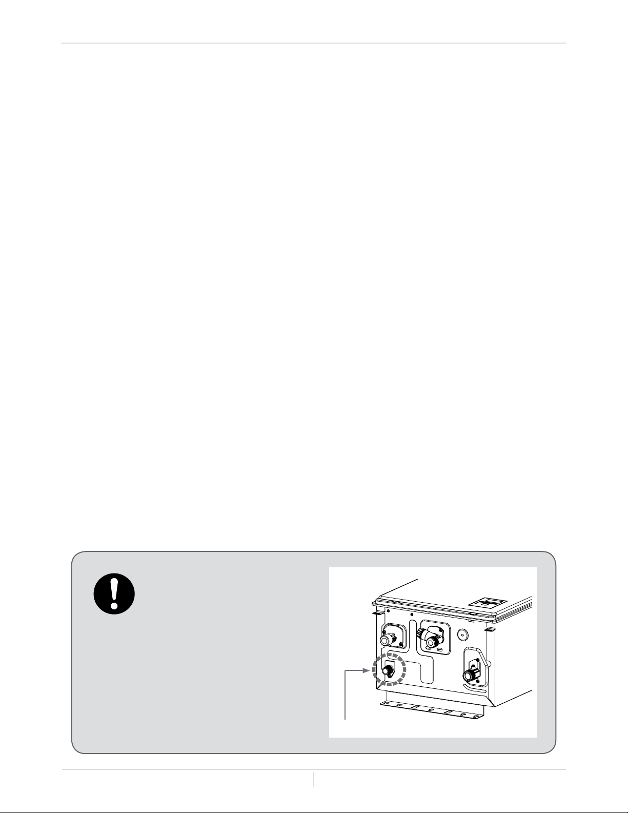
1. Turn off all electric power to the micro-boiler if service is to be performed.
2. Turn the manual gas valve located on the outside of the micro-boiler to
the off position.
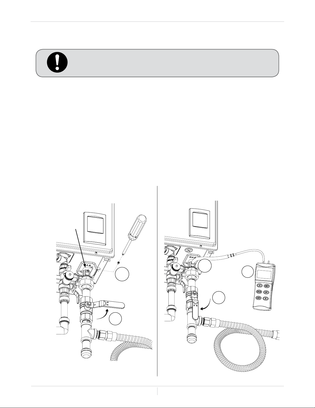
-Measuring inlet gas pressure-
The micro-boiler cannot perform properly without sufcient inlet gas pressure. Below are
instructions on how to check the inlet gas pressure. THIS IS ONLY TO BE DONE BY A LICENSED
PROFESSIONAL.
• Shut off the manual gas valve on the gas supply line.
• Remove the screw from the pressure port located on the gas inlet of the micro-boiler shown in the
diagram on the right.
• Connect the manometer to the pressure port.
• Re-open the manual gas valve. Check to see that there are no gas leaks. Take a reading of the
gas pressure. Turn up a room thermostat to activate the boiler.
• Check the inlet gas pressure. Take another reading. When the micro-boiler is on maximum and
minimum burn, the manometer should read from 5.0” to 10.5” W.C. (1.24 to 2.61 kPa) for Natural
gas, or from 8.0” to 14.0” W.C. (1.99 to 3.48 kPa) for Propane. Verify that the pressure drop is
acceptable.
Installation - Gas
1
2
3
5
4
10.0"
W.C.
Pressure Port
Installation Manual
Page
26
Follow all code requirements
of the local authority on
condensate neutralizers
and whether or not they are
required for the installation.
-CONDENSATE DRAIN-
-Pressure relief valve-
The micro-boiler has a high-temperature shutoff switch built in as a standard safety feature (called
a Hi-Limit switch) therefore a "pressure only" relief valve is required. If you are using Hydro Smart
pre-built panels the pressure relief valve will be on the primary(boiler) loop of the Master Panel and an
additional pressure relief valve may not be needed, check local codes.
• This micro-boiler does not come with an approved pressure relief valve.
• An approved pressure relief valve must be installed on the hot water outlet.
• The pressure relief valve must conform to ANSI Z21.22 or CAN 1-4.4 and installation must follow
local codes.
• The discharge capacity must be at least 120,000 BTH/h.
• The pressure relief valve needs to be rated for a maximum of 75 psi (0.5 MPa).
• Attach the discharge piping for the pressure relief valve and run the end of the tube to within 6
inches (152 mm) from the oor. This discharge tube must allow free and complete drainage without
any restrictions.
• If the pressure relief valve installed on the micro-boiler discharges periodically, this may be due to
a defective thermal expansion tank, defective pressure relief valve, or it could be signs of internal
scale build up.
• The pressure relief valve must be manually operated periodically to check for correct operation.
• No valves may be placed between the relief valve and the micro-boiler.
• The micro-boiler does not include a built-in condensate neutralizer cartridge for reducing the pH
level of condensate water. If local codes dictate that condensate must be neutralized prior to
drainage, a condensate neutralizer must be installed. An accessory Neutralizer assembly is sold
separately.
• In the absence of applicable local codes and regulations, the manufacturer recommends that
condensate be disposed of into a standard drain. Connect a drain tube from the condensate drain
port (shown below) located on the bottom of the micro-boiler to a standard drain.
Condensate drain port
Installation
Installation Manual
Page
27
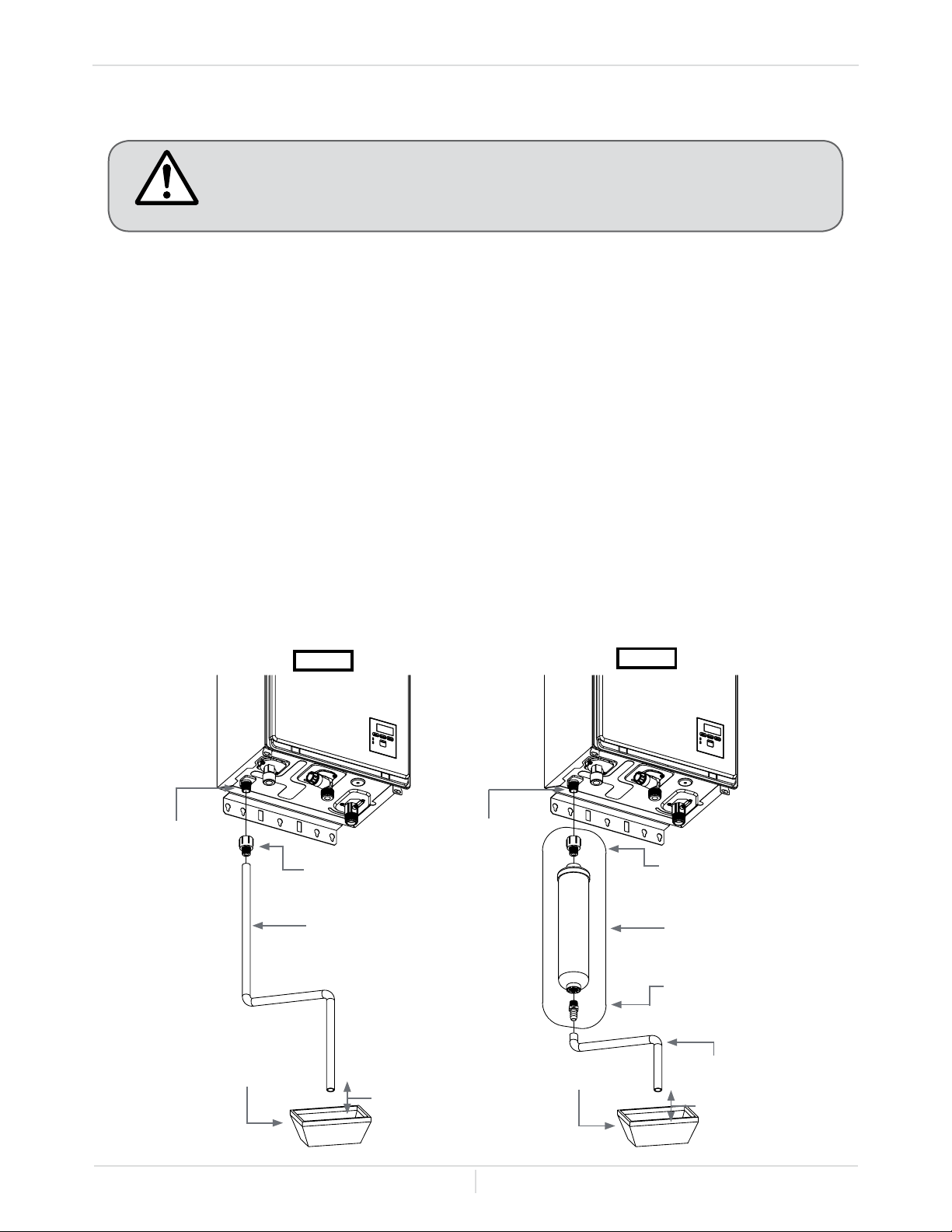
Discharge condensate (acidic water) in accordance with all local codes and
common safety practices.
Condensate
drain port
1/2" Condensate
drain tube
Adequate space
Drain
1/2" FPT x 3/8" MPT
(Included with
Neutralizer accessory)
Neutralizer cartridge
(Included with
Neutralizer accessory)
3/8" MPT x 1/2" HB
(Included with
Neutralizer accessory)
Drain
3/8" or 1/2"
Condensate
drain tube
Condensate
drain port
1/2" FPT x 3/8"
(or 1/2") HB
Adequate space
Case A
Case B
Installation
WARNING
-Condensate Drain Connections-
The micro-boiler is a high efciency condensing model that produces condensate (acidic water). The
acidic condensate generated in the secondary heat exchanger can be neutralized by the Neutralizer
accessory.
Case A: If a neutralizer is not required
1. Connect a 1/2" FPT x 3/8" (or 1/2") HB Adapter to the condensate drain port at the bottom of the
micro-boiler.
2. Connect a condensate drain tube to the 1/2" FPT x 3/8" (or 1/2") HB Adapter. The manufacturer
recommends the material of the condensate tube to be either EPDM or PVC.
3. Leave an adequate amount of space between the end of the drain tube and the actual drain, to
facilitate proper drainage.
Case B: If a neutralizer is required (installing the Neutralizer assembly)
1. Connect the 1/2" FPT x 3/8" MPT adapter to the condensate drain port at the bottom of the micro-
boiler.
2. Connect the Neutralizer to the 3/8" MPT connection of the adapter. There is a ow direction
indicator on the neutralizer. Please orient the neutralizer in the proper direction.
3. Connect a 1/2" drain tube to the other end of neutralizer.
4. Leave an adequate amount of space between the end of the drain tube and the actual drain, to
facilitate proper drainage.
Installation Manual
Page
28
When servicing or replacing parts within the micro-boiler, label all wires prior
to disconnection to facilitate an easy and error-free reconnection. Wiring
errors can cause improper and dangerous operation. Verify proper operation
after servicing.
Follow the electrical code requirements of the local authority having
jurisdiction. In the absence of such requirements, follow the latest edition of
the National Electrical Code ANSI/NFPA 70 in the U.S. or the latest edition of
CSA C22.1 Canadian Electrical Code Part 1 in Canada.
-ELECTRICAL CONNECTIONS-
• The condensate drain is at atmospheric pressure (non-pressurized) and
therefore must be allowed to drain freely with gravity only. Please ensure
that there are no blockages along the condensate drain tube. All portions
of the condensate drain (neutralizer and drain tube) must be at a lower
elevation than the micro-boiler to prevent condensate water from building
up inside the heat exchanger.
• Condensate cannot be effectively neutralized if the neutralizer elements
inside the Neutralizer accessory have been completely consumed. If this
happens condensate will remain acidic and can possibly cause damage
to items such as pipes, concrete, etc., if drained improperly.
• The Neutralizer cartridge is designed to last for 3 years before
replacement. However, the actual life of the neutralizer may vary,
depending on the application and usage. Please ensure that the
cartridge is properly replaced before the neutralizer elements have been
completely consumed.
• All preventive measures and safety practices must be adhered to when
draining condensate. The manufacturer will not be responsible for any
damage caused by condensate.
• A drain pan, or other means of protection against water damage, is
required to be installed under the micro-boiler in case of leaks.
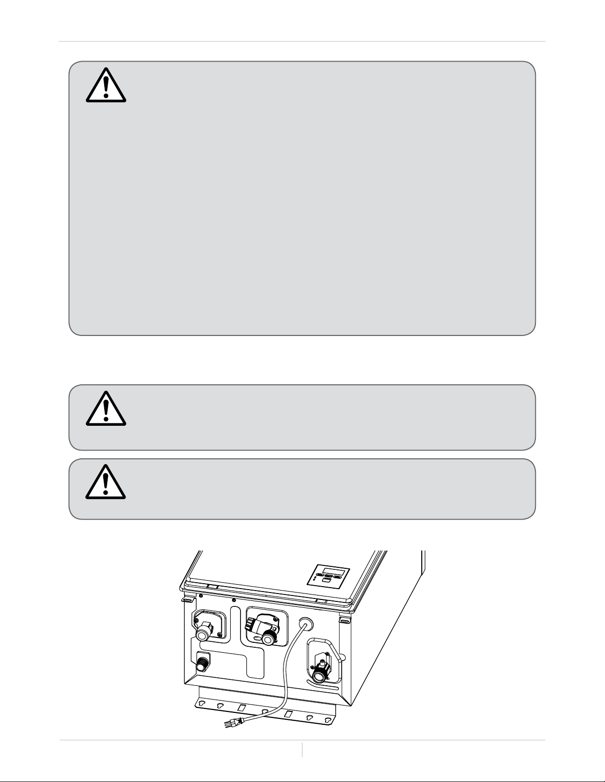
All micro-boilers come with a power plug instead of a junction box.
Installation
CAUTION
WARNING
WARNING
Installation Manual
Page
29
Installation
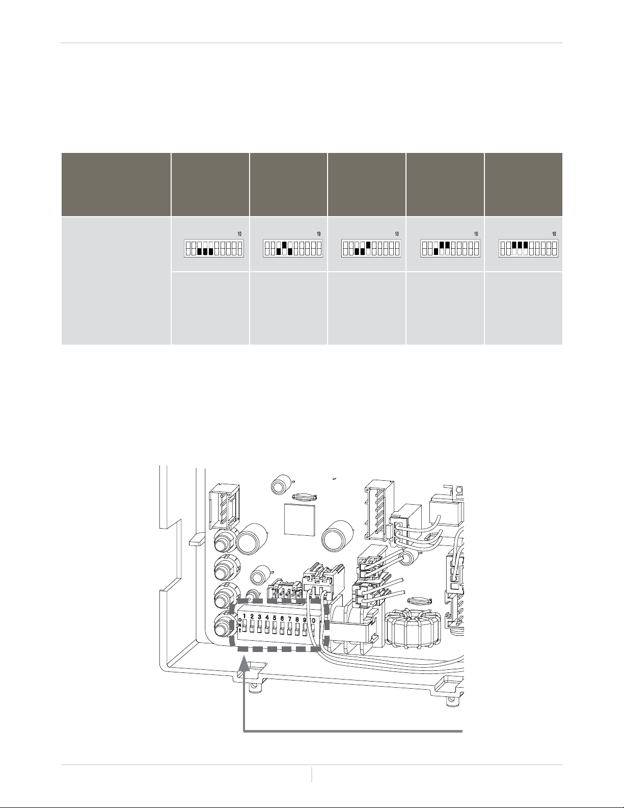
Check the elevation where your micro-boiler is installed. Set DIPswitches shown in the tables below
depending on the altitude.
Altitude
0 to 2,000 ft.
(DEFAULT)
2,000 to
3,000 ft.
3,000 to
5,000 ft.
5,000 to
7,500 ft.
7,500 to
10,100 ft.
DIPswitches
No. 3 : OFF
No. 4 : OFF
No. 5 : OFF
No. 3 : OFF
No. 4 : ON
No. 5 : OFF
No. 3 : OFF
No. 4 : OFF
No. 5 : ON
No. 3 : OFF
No. 4 : ON
No. 5 : ON
No. 3 : ON
No. 4 : ON
No. 5 : ON
1 2 3 4 5 6 7 8 9
10
OFF
ON
1 2 3 4 5 6 7 8 9
10
OFF
ON
Bank of DIPswitches
Computer board
NOTE: The dark squares indicate the direction the DIPswitches should be set to.
Only adjust the necessary switches.
1 2 3 4 5 6 7 8 9
10
OFF
ON
1 2 3 4 5 6 7 8 9
10
OFF
ON
1 2 3 4 5 6 7 8 9
10
OFF
ON
-HIGH-ALTITUDE INSTALLATIONS-
Installation Manual
Page
30
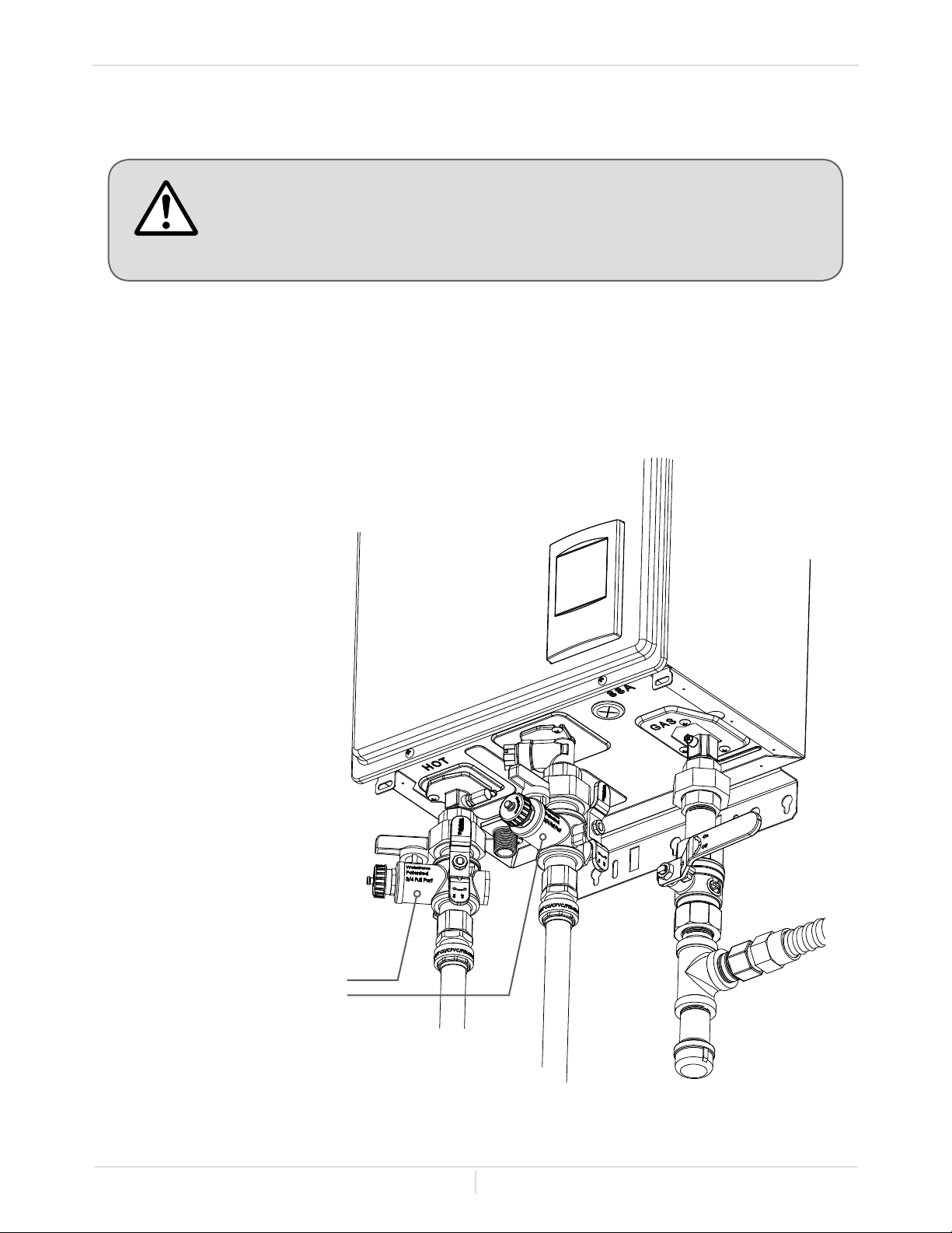
-Water Connections-
• Do not use this micro-boiler if any part has been submersed under water.
Immediately call a licensed professional to inspect the micro-boiler to
replace any damaged parts.
• Do not reverse the hot outlet and cold inlet connections to the micro-
boiler. This will not properly activate the micro-boiler.
CAUTION
• All pipes, pipe ttings, valves and other components, including soldering materials, must be
suitable for space heating systems.
• We recommend using an isolation valve set with hose bibs for serviceability. See maintenance and
service section. Contact Hydro Smart at 1-763-331-3066 to order a isolation valve/service kit.
Boiler Supply
Boiler Return
Isolation Valve / Service Kit
Product # 4443W
3/4" FPT ball v. Iso w/drains
Installation
Installation Manual
Page
31
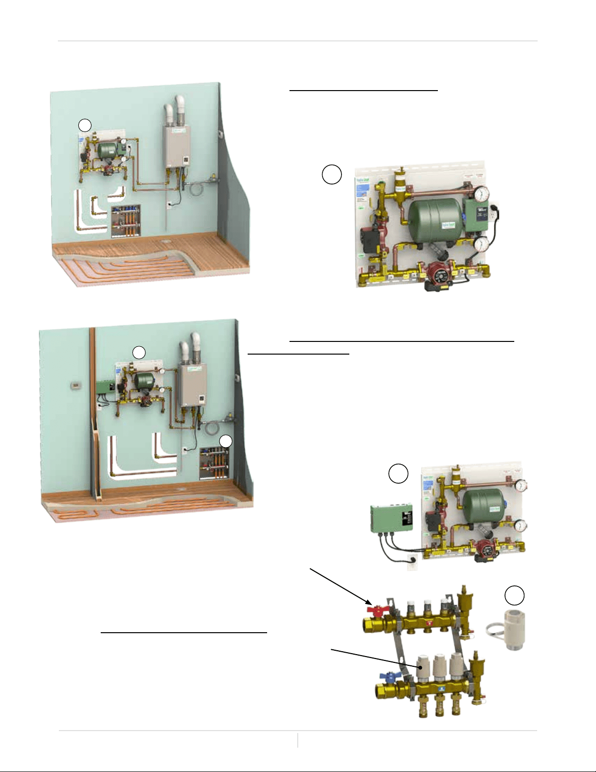
APPLICATIONS
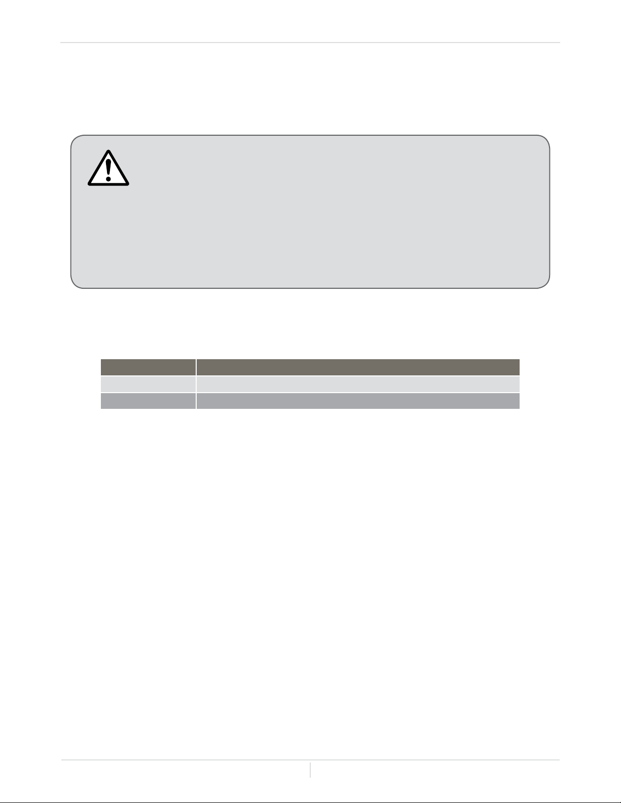
-Space heating applications-
• In order to purge air in water pipes within a closed-loop system, an
air vent, air separator, and expansion tank should be installed in
the system. The system must follow primary/secondary plumbing
design specication. (Optional Hydro Smart pre-built space heating
panels incorporate all these features and are located in the optional
accessories section starting on p. 34.
• Water temperature over 125° F (52° C) can cause severe burns
instantly or death from scalding.
• Chemicals such as diluted Glycol can be used for radiant oor heating
only. The diluted solution of glycol must contain between 25 and 50 %
of Glycol. Be aware that in closed-loop glycol systems, low pressure
in the heat exchanger can cause low-temperature boiling, resulting
in excessive noise and damage to the micro-boiler. Consult with the
glycol maker for specications prior to use.
• The micro-boiler manufacturer requires primary/ secondary plumbing
congurations for space heating applications. See description below.
WARNING
The Hydro Smart panel systems operate on a principal of hydraulic separation between the boiler
circuit and the emitter circuit (tubing, baseboard, ect.). This hydraulic separation creates the ability to
adjust the ow in the boiler circuit independently from the emitter circuit while still passing heat from
the boiler to the emitters. Flow rate from boilers need to be adjusted to manufacturer's specications.
Flow rate for emitters need be adjusted for heat output performance.
For more information on hydraulic separation visit this website:
www.calef.com/sites/default/les/le/hydraulicseparation-tr07.pdf
-Hydraulic Separation-
Installation
Installation Manual
Page
32
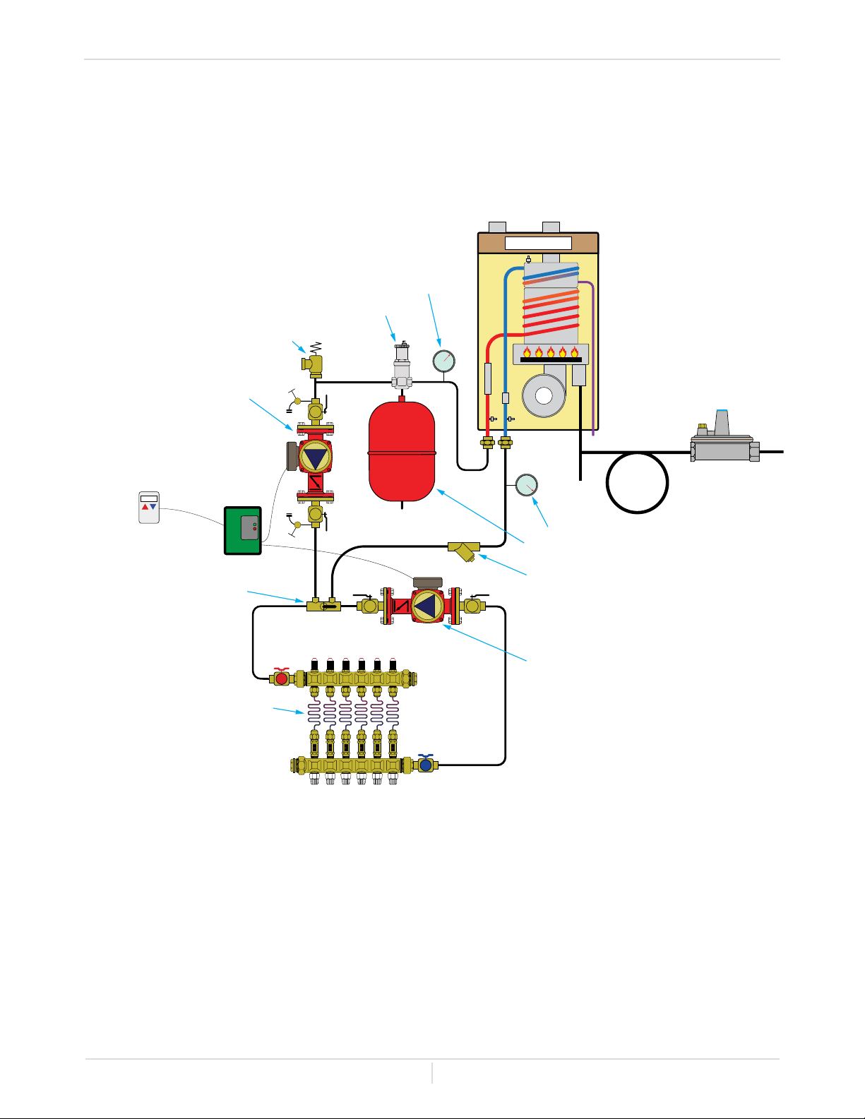
-One zone plumbing example-
primary/
secondary fitting
manifold station with
balancing & sight flow valves
--
--
--
--
--
--
--
--
--
--
--
--
--
--
--
--
--
--
--
--
--
--
--
--
--
--
--
--
--
--
--
--
--
--
--
--
Secondary Circulator
Stiebel Eltron or Gundfos
circulator w/
internal check valve &
isolation flanges
Primary Circulator
Stiebel Eltron or Gundfos
circulator w/
internal check valve
isolation flanges &
purge valve
HS120
Modulating/
Condensing boiler
HYDRO SMART
pressure relief valve
pump controller
thermostat
air separators
supply pressure/ temp gauge
diaphragm type expansion tank
return pressure/temp gauge
y-strainer
tubing in concrete
gas regulator
Installation
* This diagram illustrates tankless micro-boiler design concepts only and does not accurately
represent to micro-boilers description.
Installation Manual
Page
33
FOR YOUR SAFETY, READ BEFORE OPERATING
• Check the GAS and WATER CONNECTIONS for leaks before ring unit for the rst
time.
• Open the main gas supply valve to the micro-boiler using only your hand to avoid any
spark. Never use tools. If the knob will not turn by hand, do not try to force it; call a
qualied service technician. Forced repair may result in a re or explosion due to gas
leaks.
• Be sure to check for the presence of leaking gas toward the bottom of the micro-boiler
because some gases are heavier than air and may settle towards the oor.
• Check the GAS PRESSURE. Refer to p. 25.
• Do not try to light the burner manually. It is equipped with an electronic ignition device
which automatically lights the burner.
• Check for PROPER VENTING and COMBUSTION AIR to the micro-boiler.
• Purge the GAS and WATER LINES to remove any air pockets.
• Do not use this micro-boiler if any part has been submersed under water. Immediately
call a qualied service technician to inspect the micro-boiler and to replace any damaged
parts.
IF YOU SMELL GAS:
• Do not try to start the micro-boiler.
• Do not touch any electric switches; do not use any phone in your building.
• Immediately call your gas supplier from a neighbor's phone. Follow the
gas supplier's instructions.
• If you cannot reach your gas supplier, call the re department.
OPERATION
1.
Turn on the thermostat and verify that uid ows through
your radiant system. Then turn off your thermostat.
2. Fully open the manual gas control valve installed.
3.
Turn on the 120 Vac, 60 Hz power supply to the micro-
boiler.
4.
Now turn on the thermostat. You are ready to enjoy hours of
endless comfort.
-INITIAL OPERATION-
WARNING
Installation
Installation Manual
Page
34
Optional Items
OPTIONAL ITEMS
-Venting Options-
# ITEM CATALOG #
1. 3- inch Concentric PVC Termination HS-CVent-3
2. 4- inch Backow Preventer HS-2ZVB04
3. 3/4 in. Flexible Gas Pipe ConnGasFlex34
4. 1/2 in. Gas Regulator (LP and NG) RegGasLP12 / RegGasNG12
5. 3/4 in. Gas Regulator (LP and NG) RegGasLP34 / RegGasNG34
6. Master Pro One Zone Panel HSPS120LT
7. Master Pro Integrator Panel - Zoning by Actuator HSPS120MTL
8. 24 Vac Actuator 656314
9. Master Pro Integrator Panel - Zoning by Pump HSPS120MPL
10. Master Pro Integrator Panel - Zoning by Zone Valve HSPS120MZL
11. Zone Pro 2 Zone Panel - Zoning by Pump HS1T2ZPMP
12. Zone Pro 3 Zone Panel - Zoning by Pump HS1T3ZPMP
13. Zone Pro 4 Zone Panel - Zoning by Pump HS1T4ZPMP
14. Zone Pro 2 Zone Panel - Zoning by Zone Valve HS1T2ZZV
15. Zone Pro 3 Zone Panel - Zoning by Zone Valve HS1T3ZZV
16. Dual Purpose Domestic and Space Heating Panel CB-PE30MV-120HT120DW
Item #2: 4- inch Backow Preventer - There are two functions available for
this adapter, which can be connected with the micro-boiler and category III
venting and prevents the back-ow of air through the exhaust vent. This helps
prevent harmful exhaust gases from entering the home, as well as helping to
prevent the micro-boiler from freezing in areas where cold air can be blown
or drawn into the exhaust system. Install this adapter in accordance with the
installation instructions that are packaged with the adapter and any applicable
codes.
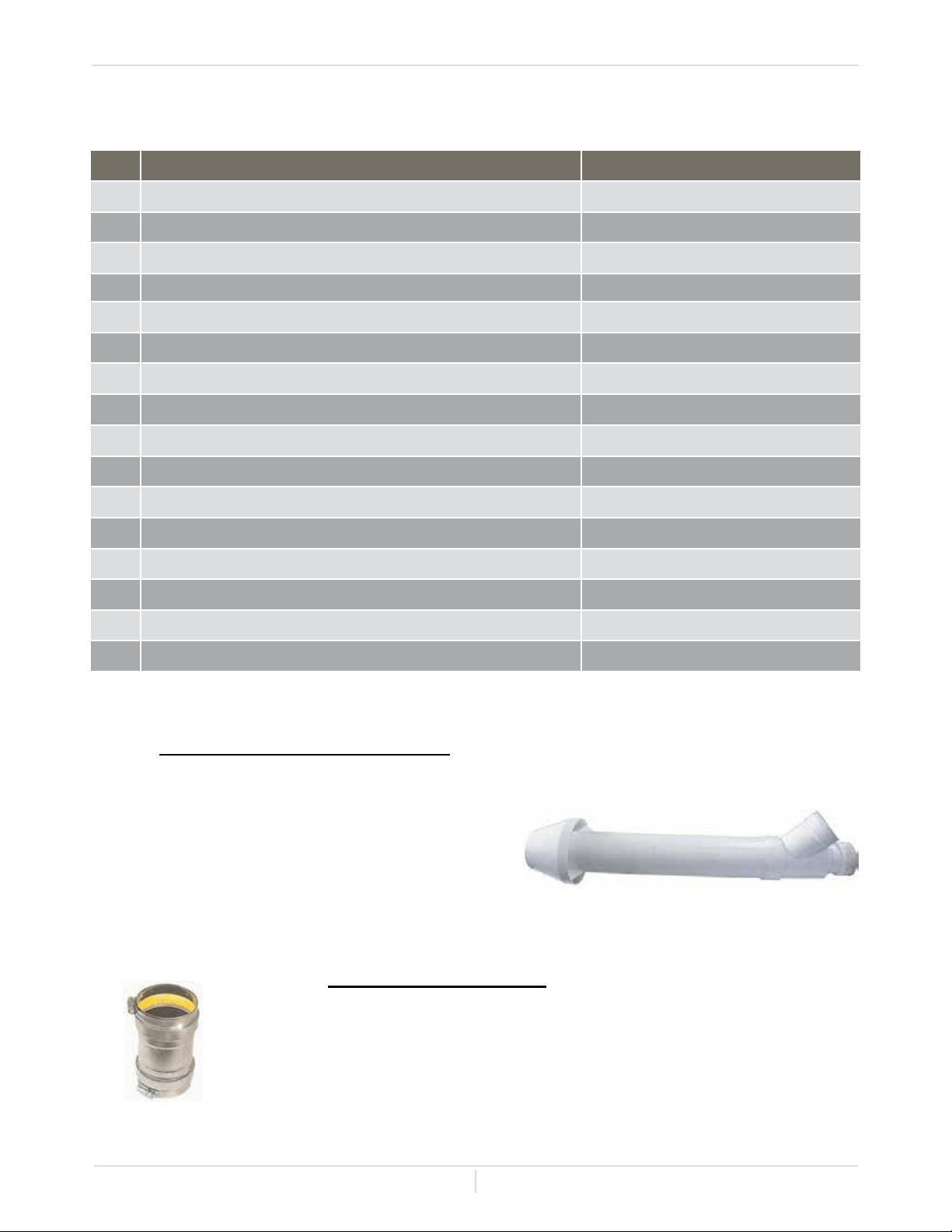
Item #1: 3- inch Concentric PVC Termination -
Used when terminating direct-vent (seal combustion)
systems, with boilers that require a 3 in. (76 mm)
intake and a 3 in. (76 mm) exhaust. This concentric
termination provides the convenience of only having
to make one penetration through a sidewall instead of
two separate penetrations for the intake and exhaust
piping. The termination includes a bird screen,
restricting small animals, pests, and foreign objects
from entering into the vent system.
Installation Manual
Page
35
Optional Items
-Pre-built Heating Panels Options-
-Gas Options-
Hydro Smart-Pre built Heating Panels -Hydro Smart micro-boilers require primary / secondary
plumbing. Pre-built panels from Hydro Smart make installing you system easy. We do all the
engineering and you just bolt it to the wall. Hydro Smart pre-built space heating panels: Call tech
support (1-763-331-3066) for order assistance.
Features:
Master Panels
• 3/4" FPT boiler supply and return connections
• 1" Quick Connect (Pex or Copper) supply and return connections
• 120,000 btu capacity
• 3-spd circulator (0-19 FT HD, 0-17 GPM) with check valve on primary and secondary circuits
• Panel dimensions: 26.25 in. HT x 26 in. WD x 10 in. HT
• Max. Temperature: 155° F
• Max. Operating Pressure: 50 psi.
Zoning Panels
• 1" Quick Connect (Pex or Copper) supply and return connections
• 3/4" FPT zone / emitter connections
• 190,000 btu capacity
• Zone Control Options: 3-spd circulator with check valve, 24 Vac Zone Valves, or 24 Vac Actuators
• Panel dimensions: 26 in. - 32.5 in. HT x 26 in. WD x 6.5 in. DP
• Max. Temperature: 190° F
• Max. Operating Pressure: 50 psi.
Item #3: 3/4 in. Flexible Gas Pipe - This 1 inch OD, 3/4" ID, durable,
corrosion-resistant stainless steel gas connector is congured with 3/4"
MIP x 3/4" FIP adapters and is 36 inches in length. Designed with safety
in mind, this CSA approved gas connector is coated with an antimicrobial
PVC for unmatched protection from weather and abuse. It is commonly
used for the installation of appliances with a high BTU requirement.
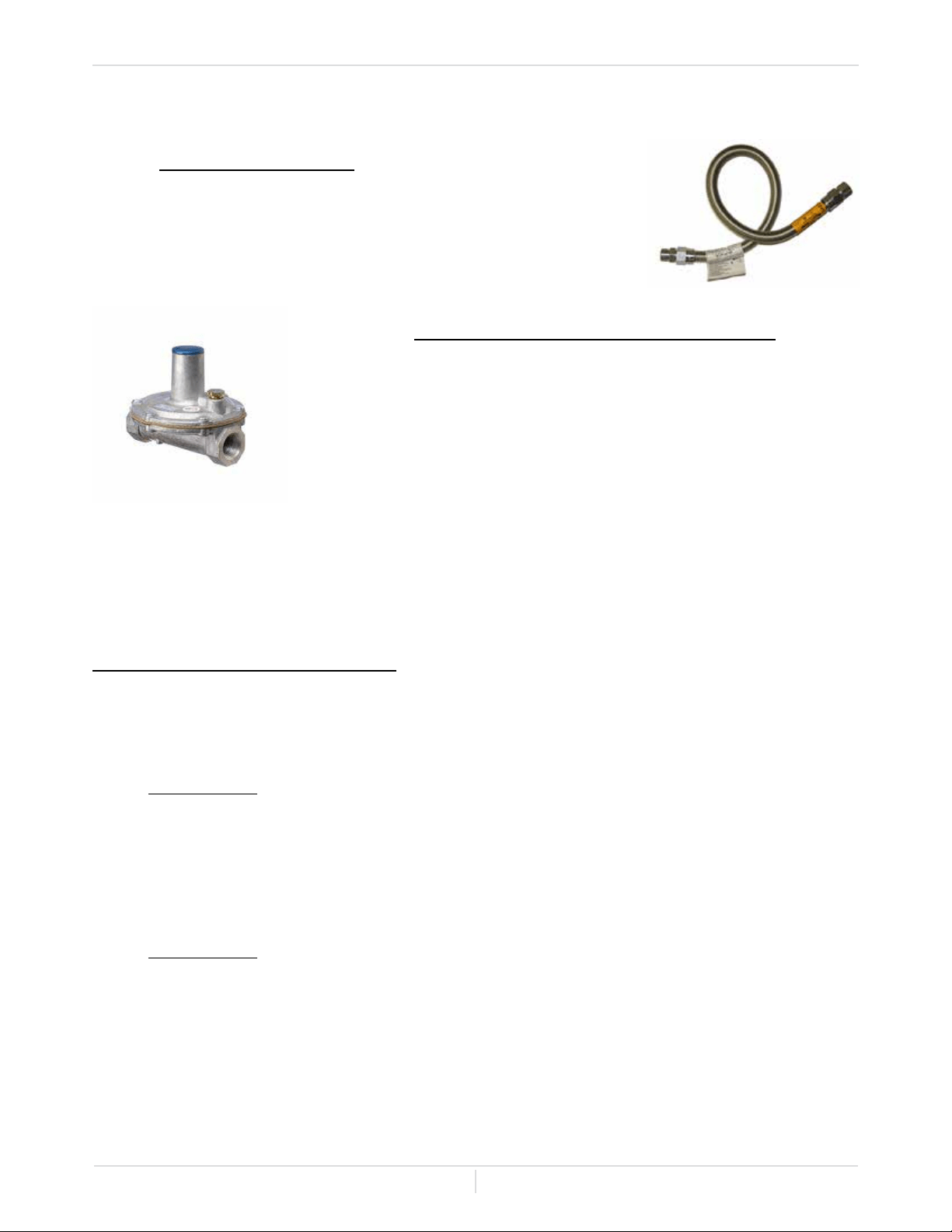
Item #4 & #5: 1/2in. and 3/4 in. Gas Regulators(LP and NG) - These
gas appliance and line pressure regulators are designed to supply
precise regulating control to ow of Liquid propane or Natural gas used
in residential, commercial and industrial applications. In the absence of
ow, these regulators guarantee excellent control of the outlet pressure.
These regulators have female NPT connections and a venting outlet
of 3/8" NPT. They have a maximum inlet pressure of 2 PSIG with
300,000BTU/hr capacity, a spring range of 7 to 11 inches. These units
have a spring set point of 11" W.C. for Liquid propane and 8" W.C. for
Natural Gas.
Installation Manual
Page
36
-One zone system-
-Multi zone by Actuator/Telestat system-
Optional Items
Item #6: HSPS120LT (One zone panel) - This Master One
Zone Panel (Low Temp-Max. 155° F) is utilized when 1
thermostat zone is required in the system. The panel extracts
the heated uid from the boiler and processes the heated
uid to the emitter circuit. Boiler and emitter circuits have
hydraulic separation for independent ow adjustments.
Item #7: HSPS120MTL (Master Pro Integrator Panel -
Zoning by Actuator) - This Master Zoning by Actuator
Panel (Low Temp-Max. 155° F) utilizes primary/secondary
plumbing just like the one zone panels. This panel would be
a great choice when you have multiple zones with emitters
that have the same water delivery temperatures, less than
1800 sqft. total and can bring all the loops to 1 central
manifold. Note: This options requires 1 actuator( Item
#8) for each loop/run of your system (6 Max.) Each zone
must have min. of 600 sqft.
Item #8: Thermo-Electric Zoning Actuator - Actuators
open and close when thermostats call for heat and can
be grouped together for thermostatically controlled zones
with more than 1 loop (there should always be a minimum
of 2 loops per zone). These actuators have a control knob
for manual opening, valve opening/closing indicator and a
device for returning to automatic operation from the manual
position.
Hydronic Manifold - Always use a hydronic manifold
not a potable water manifold for your radiant heating
system. Hydronic manifolds have ow control valves
and site ow gauges. Ideal ow rate of .5 to .8
GPM per loop/run. (Call 1-763-331-3066 for order
assistance.)
6
6
7
7
8
8
Installation Manual
Page
37
Optional Items
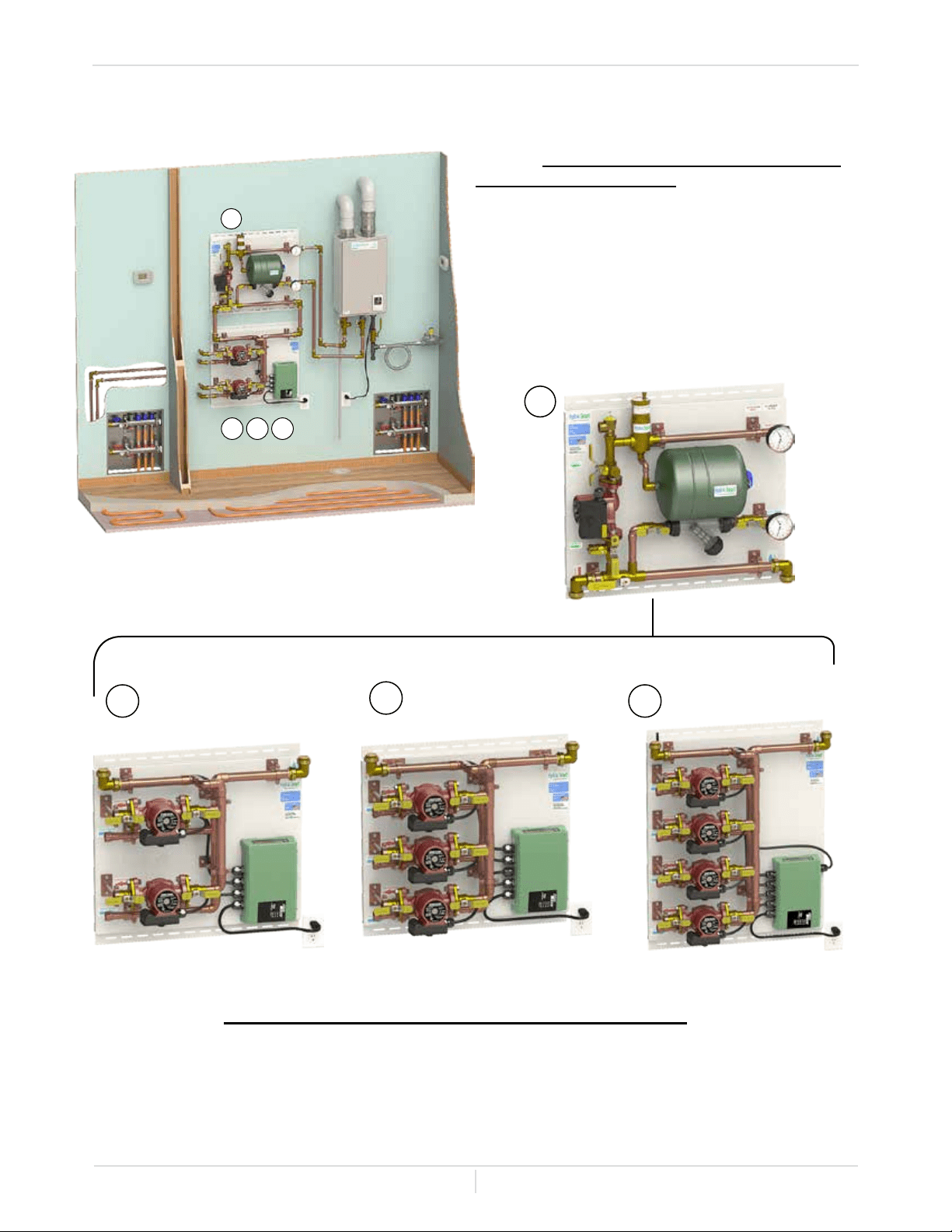
Item #9: HSPS120MPL (Master Pro Integrator
Panel - Zoning by Pump) - This Master Zoning
by Pump Panel (Low Temp-Max. 155° F) utilizes
primary/secondary plumbing. This panel would be
a great choice when you have multiple zones with
low temperature emitters (100° F - 130° F) and
would like to maintain constant pressure on each
zone. A pump panel system can handle up to 1800
sqft per zone and 3600 sqft for the total system.
Note: Each zone must have min. of 600 sqft.
-Multi zone by Pump system-
Item #10, 11, 12: HS1T2ZPMP, HS1T3ZPMP, HS1T4ZPMP (2 - 4 Zone Panel) - These Zoning
Panels paired with the HSPS120MPL panel will supply heat to 2 - 4 thermostatically controlled
zones. Each pump will handle from 600 sqft to 1800 sqft (Max. 3600 sqft) or 2 to 6 loops /runs of
tubing (Max. 12 loops /runs) in concrete. The advantages of zoning by pumps is less variation in
ow rate and minimization of head loss. Please contact Hydro Smart at 1-763-331-3066 for technical
assistance when ordering.
9
9
10
10
11 12
11
12
Installation Manual
Page
38
13
14 15
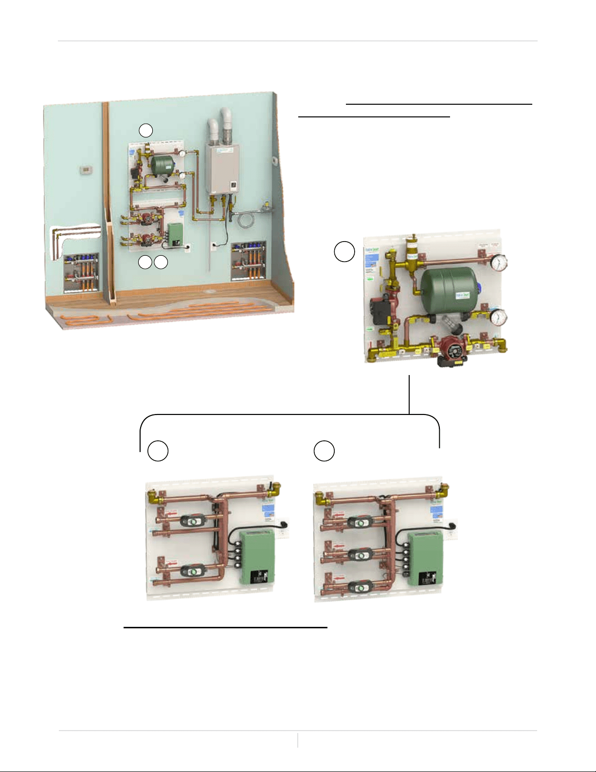
Item #13: HSPS120MZL (Master Pro Integrator
Panel - Zoning by Zone Valve) - This Master
Zoning by Zone Valve Panel (Low Temp-Max.
155° F) utilizes primary/secondary plumbing.
This panels zoning is similar to Item #7. I would
recommend this system when you choose to
control your zone by the entire manifold and not
by the individual loop. Note: Each zone must
have min. of 600 sqft.
-Multi zone by Zone Valve system-
Item #14, 15: HS1T2ZZV, HS1T3ZZV (2 - 3 Zone Panel) - These Zoning Panels paired with the
HSPS120MZL panel will supply heat to 2 - 3 thermostatically controlled zones. Each zone valve will
handle from 600 sqft to 1800 sqft (System Max. 1800 sqft) or 2 to 6 loops /runs of tubing (System
Max. 6 loops /runs) in concrete. The secondary circulator on the master panel supplies ow to the
emitters and the zone valves, controlled by a room thermostat determine which zone or area the ow
will go to. Please contact Hydro Smart at 1-763-331-3066 for technical assistance when ordering.
13
14 15
Optional Items
Installation Manual
Page
39
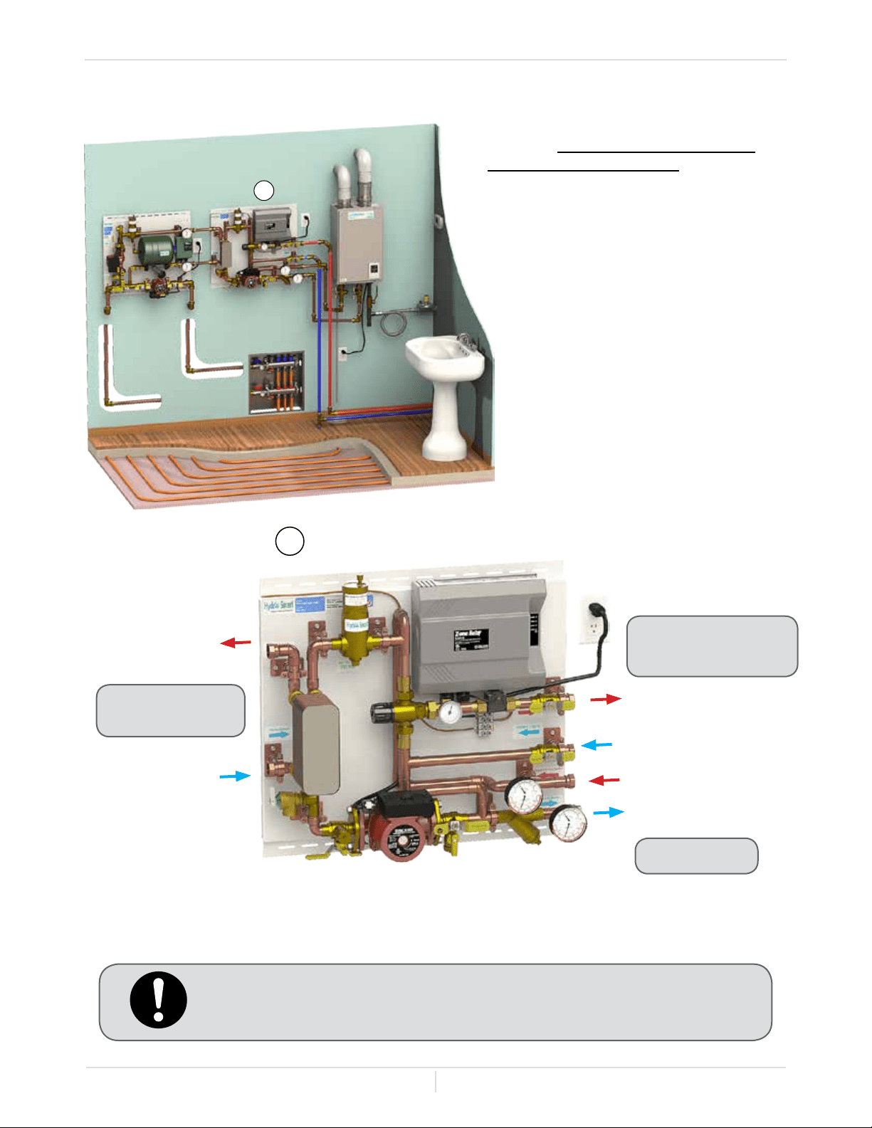
16
Follow all local codes, or in the absence of local codes, follow the most
recent edition of the National Standard Code, ANSI Z21.10.3.
To Domestic Potable
Water System
To Space Heating
Panel System
To Boiler
Space Heating Supply
Space Heating Return
Boiler Supply
Boiler Return
Hot Potable Water Out
Cold Potable Water In
Item #16: CB-PE30MV-120HT120DW
(Potable Hot Water Panel) - Insert a
Hydro Smart Dual Purpose Panel into your
space heating system to provide potable
heated water. Call tech support (1-763-
331-3066) for sizing assistance.
-Dual Purpose panel (Domestic and Space Heating)-
16

Owner's Guide
Page
40
CONGRATULATIONS
Owner's Guide
Congratulations and thank you for choosing our condensing micro-boiler. Before use, we recommend
that you read through this safety manual carefully. Please refer to the back of the manual for details
about the warranty. Keep this manual for future reference.
If you lose the manual, contact the manufacturer or your local distributor. When you call, please tell us
the model number and the serial number of your unit written on the rating plate of the micro-boiler.
Owner's Guide
Page
41
If you do not follow these instructions exactly, a re or explosion may result
causing property damage, personal injury or loss of life.
OPERATING SAFETY
-For your safety read before operating-
A. This micro-boiler does not have a pilot. It is equipped with an ignition device that automatically
lights the burner. Do not try to light the burner by hand.
B. BEFORE OPERATING smell all around the micro-boiler area for evidence of leaking gas. Be
sure to smell next to the oor because some gas is heavier than air and will settle on the oor.
WHAT TO DO IF YOU SMELL GAS:
• Do not try to light any appliance.
• Do not touch any electric switch
• Do not use any phone in your building.
• If you cannot reach your gas supplier, call the re department.
C. Use only your hand to turn the gas valve knob. Never use tools. If the knob will not turn by hand,
don't try to repair it. Call a qualied service technician. Forced or attempted repair may result in a
re or explosion.
D. Do not use this micro-boiler if any part has been under water. Immediately call a qualied service
technician to inspect the micro-boiler and to replace any damaged parts.
-Operating Instruction-
1. STOP! Read the safety information above or in the Owner's Manual.
2. Turn off all electric power to the micro-boiler.
3. Do not attempt to light the burner by hand.
4. Turn the manual gas valve located on the outside of the unit clockwise to the OFF position.
5. Wait ve (5) minutes to clear out any gas. If you then smell gas,
STOP! Follow "B" in the safety
information above on this page. If you don't smell gas, go to next step.
6. Turn the manual gas valve located on the outside of the unit counterclockwise to the ON position.
7. Turn on all electrical power to the micro-boiler.
8. If the micro-boiler will not operate, follow the instructions "to Turn Off Gas to Appliance" and call
your service technician or gas supplier.
-To Turn Off Gas to Appliance-
1. Turn off all electric power to the micro-boiler if service is to be performed.
2. Turn the manual gas valve located on the outside of the unit clockwise to the OFF position.
WARNING
Owner's Guide
Page
42
Operating Safety
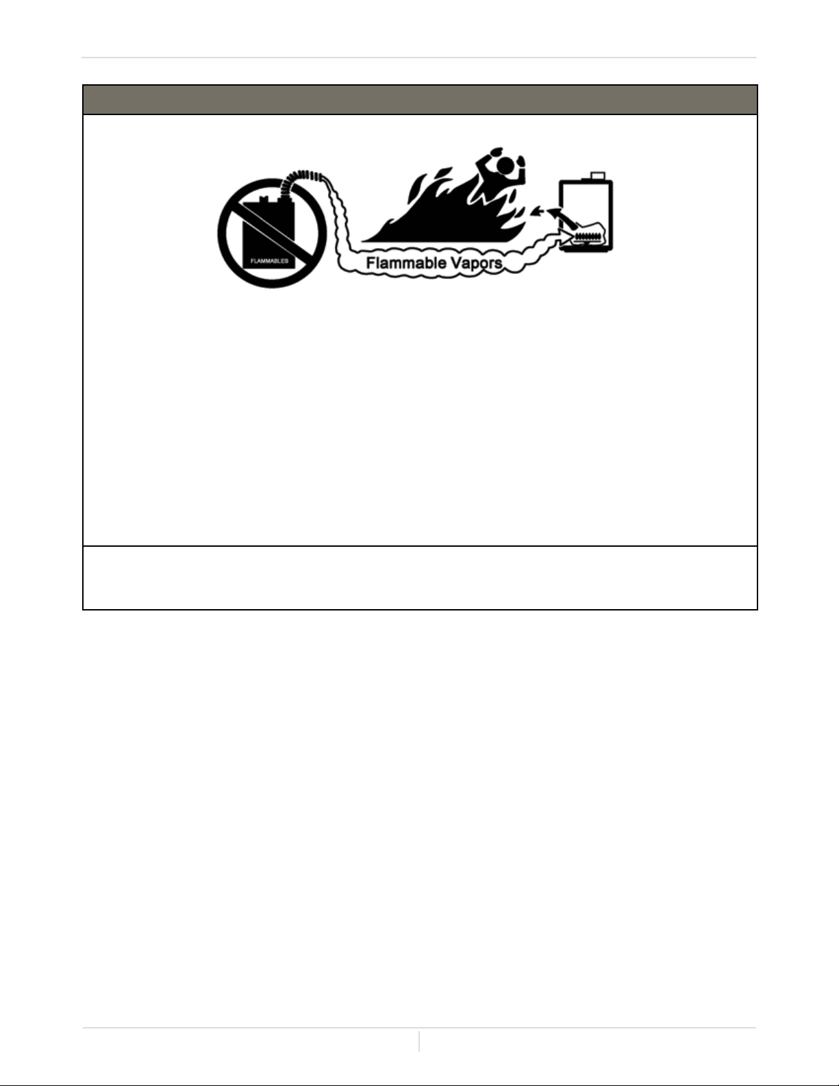
DANGER
Vapors from ammable liquids will explode and catch re causing death or severe burns.
Do not use or store ammable products such as gasoline, solvents or adhesives in the same room
or area near the micro-boiler.
Keep ammable products
1. Far away from boiler
2. In approved containers
3. Tightly containers
4. Out of children's reach
Vapors:
1. Cannot be seen
2. Vapors are heavier than air
3. Go a long way on the oor
4. Can be carried from other rooms
to the main burner by air currents
WARNING: California Proposition 65 lists chemical substances known to the state to cause cancer,
birth defects, death, serious illness or other reproductive harm. This product may contain such
substances, be their origin from fuel combustion (gas, oil) or components of the product itself.
Owner's Guide
Page
43
Normal Operation
NORMAL OPERATION
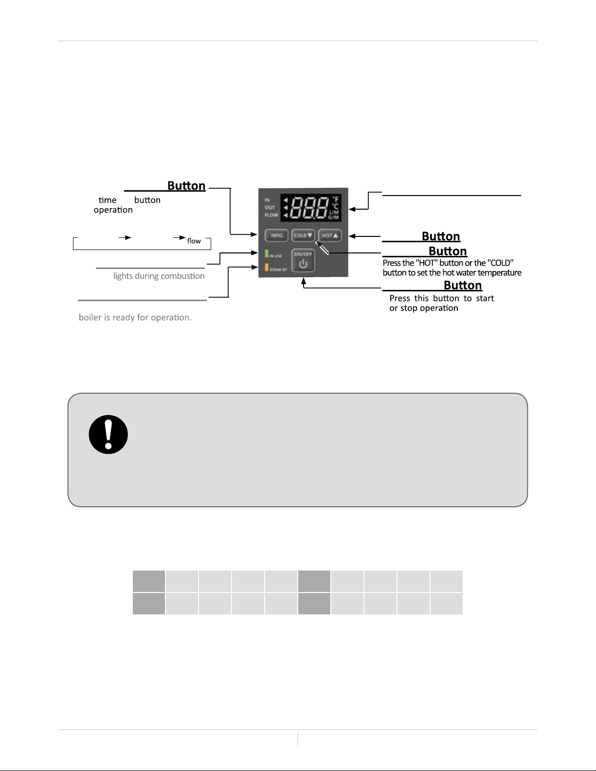
-Display of the controller-
The illustration below shows an example of the display of the controllers. The exact display may differ
from examples.
-General-
-Temperature table of the controller-
• Flow rate to activate the micro-boiler: 0.5 gallon per minute at the default
set temperature (1.9 L/min.).
• Flow rate to keep the micro-boiler running: 0.4 gallon per minute (1.5 L/min)
• The controllers have an energy saving mode. Five minutes after the micro-
boiler stops operating, the back-light of the controller turns off.
• The back-light of the controller will turn back on once the micro-boiler
begins ring again.
°F 100 105 110 115 120* 125 130 135 140
°C 38 40 43 45 50* 52 55 57 60
* Factory setting (Default)
"COLD"
"HOT"
.
"ON/OFF"
.
STANDBY LED(Orange)
The indicator turns on when the
IN USE LED (Green)
This .
When the STAND BY LED is ON, the
hot water set temperature will be
displayed.
Display for Temperature
"INFO"
Each the is pressed,
the mode is selected
in the following sequence.
Inlet water
temperature
Outlet water
temperature
Water
Owner's Guide
Page
44
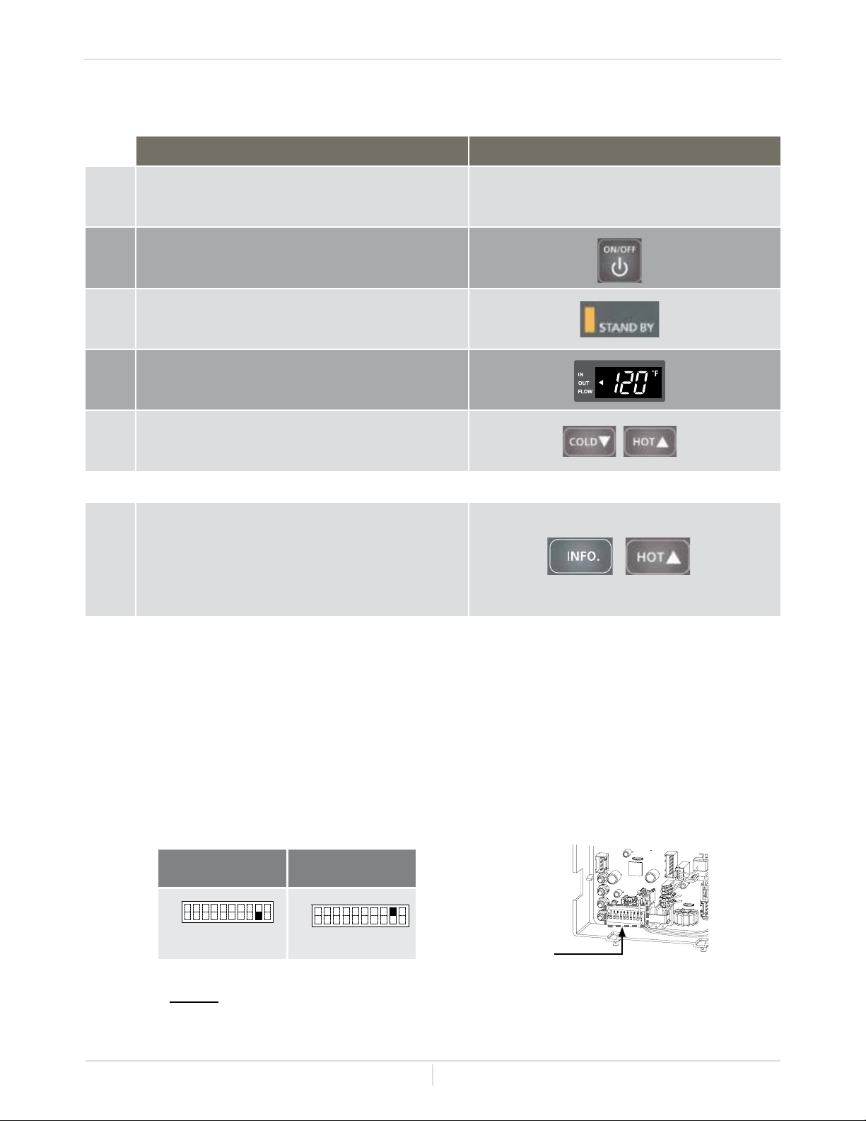
OPERATION SCREEN ON THE CONTROLLER
1.
Turn on the 120 VAC power supply to the
micro-boiler.
2.
Press the "ON/OFF" button on the controller in
order to turn the controller on.
3. When ON, the STAND BY LED is lit.
4.
It shows the set temperature on its display as
shown in the picture on the right. (EX.: 120° F)
(EX.: 120° F)
5.
Press the "HOT" button or the "COLD" button
to set the temperature setting of the unit.
Temperature setting above 120° F on Display
6.
Press the "INFO" and the "HOT" buttons
down together and hold for 3-5 secs. Release
the buttons when the display begins to
ash. Press the "HOT" button to raise the
temperature setting.
Normal Operation
-TEMPERATURE SETTINGS-
-Temperature setting on the PCB-
Without Digital Display
There are 2 preset temperatures (120° F (49° C) and 140° F (60° C)) that you can select from by
changing the DIPswitch settings on the computer board. See the table below. When the controller is
in normal operation, the set temperature of the controller is given priority over the set temperature of
the DIPswitch settings.
• The temperature has been preset at the factory to 120° F (49° C).
NOTE: Only change the switches with dark squares. The dark squares indi-
cate the direction the DIPswitches should be set to.
Computer board
Bank of
DIPswitches
120 °F (49 °C)
DEFAULT
140 °F (60 °C)
No. 9 : OFF
No. 9 : ON
OFF
ON
12 34 56 78
9
10
OFF
ON
12 34 56 78 9 10
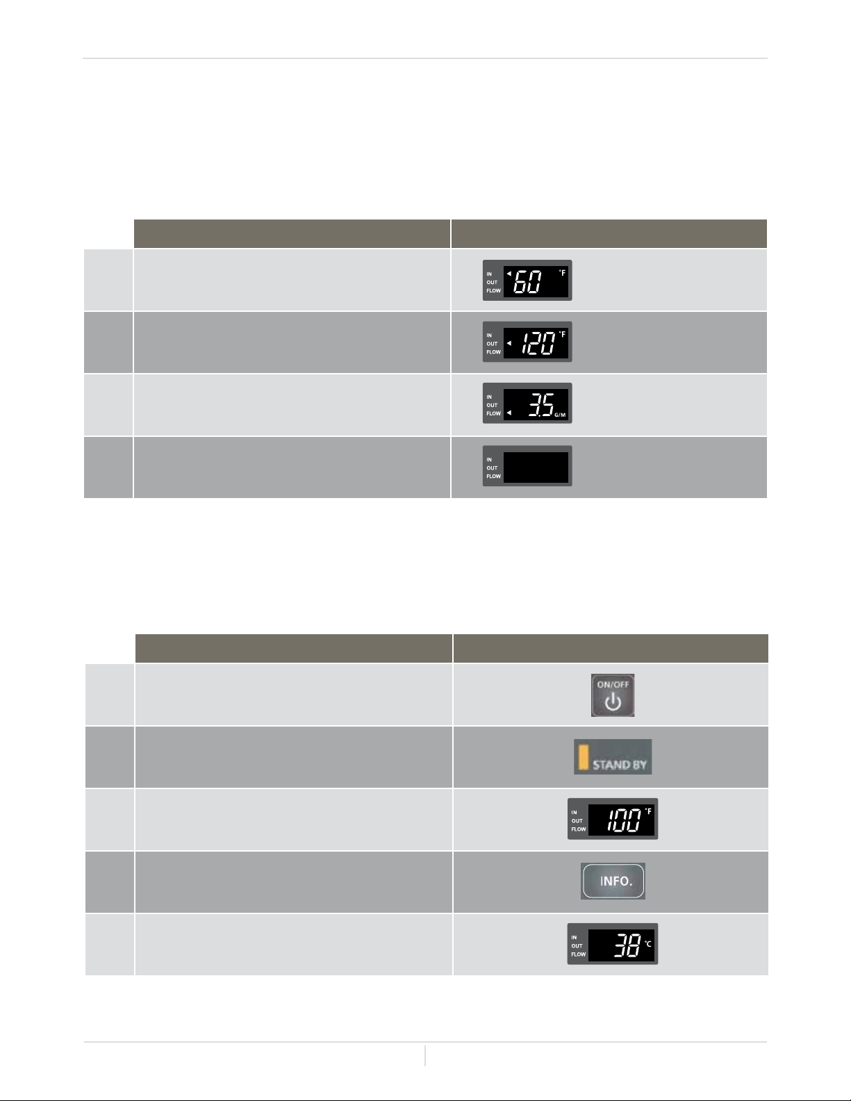
Owner's Guide
Page
45
Normal Operation
-ADDITIONAL FEATURES-
-Information mode-
You can get some information about the micro-boiler condition by pressing the "INFO" button. For
more information, follow the procedures below:
-Unit conversion mode-
The controller display information can be changed from English Units to S.I. / metric units.
Please follow the procedures below:
OPERATION SCREEN ON THE CONTROLLER
1.
Inlet water temperature will be displayed on
the controller by pressing the "INFO" button.
Inlet water temperature
(EX.: 60° F)
2.
Outlet water temperature will be displayed on
the controller by pressing the "INFO" button.
Outlet water temperature
(EX.: 120° F)
3.
Water ow rate, in GPM, will be displayed on
the controller by pressing the "INFO" button.
Water ow
(EX.: 3.5 GPM)
4.
Press the "INFO" button to nish information
mode.
OPERATION SCREEN ON THE CONTROLLER
1.
Press the "ON/OFF" button on the controller
in order to turn the controller on.
2. When ON, the orange LED is lit.
3.
The previous set temperature will be
displayed on the screen.
(EX.: 100° F)
4.
Press the "INFO" buttons for at least 3
seconds.
5.
The set temperature should now be
displayed in the alternate unit measurement.
(EX.: 38° C)
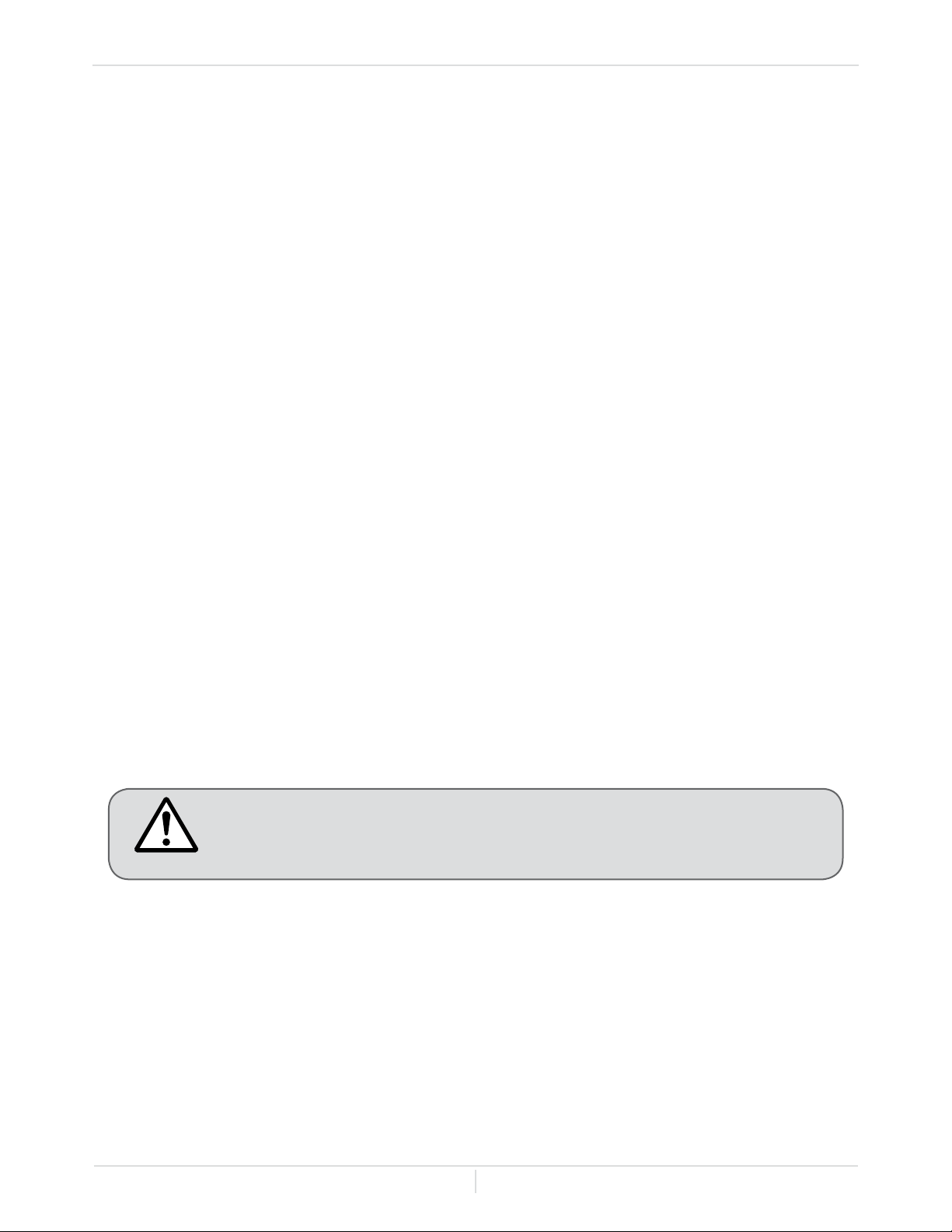
Owner's Guide
Page
46
Normal Operation
-FLOW-
-FREEZE PROTECTION SYSTEM-
• The ow rate through the micro-boiler is limited to a maximum of 7.0 GPM (26.5 L/min.).
• The temperature setting, along with the return temperature of the water in the system will
determine the ow rate output of the micro-boiler.
This will keep your micro-boiler from freezing and being damaged.
• This micro-boiler comes equipped with heating blocks to protect it against damage associated with
freezing.
• For this freeze protection system to operate, there has to be electrical power to the micro-boiler.
Damage to the heat exchanger caused by freezing temperatures due to power loss is not covered
under the warranty. In cases where power losses can occur, consider the use of a backup power
supply.
• The freeze protection system will activate when the freeze protection thermostat senses
temperatures at 36.5° F (2.5° C) or lower.
• It is the installer's responsibility to be aware of freezing issues and take all preventative measures.
The manufacturer will not be responsible for any damage to the heat exchanger as a result of
freezing.
• In any area subject to freezing temperatures, freezing issues can occur if cold air enters through
the venting into the heat exchanger by either negative pressures within the installation location
or by strong wind. The manufacturer highly recommends the use of a backow preventer (sold
separately) to minimize the amount of cold air entering through the exhaust venting when the
micro-boiler is off.
• If you will not be using your boiler for a long period of time:
1. Completely drain the water out of the micro-boiler. Refer to "-UNIT DRAINING-" on page 47.
2. Disconnect power to your boiler.
Only pipes within the micro-boiler are protected by the freeze protection
system. Any water pipes (hot or cold) located outside the micro-boiler will not
be protected. Properly protect and insulate these pipes from freezing.
CAUTION
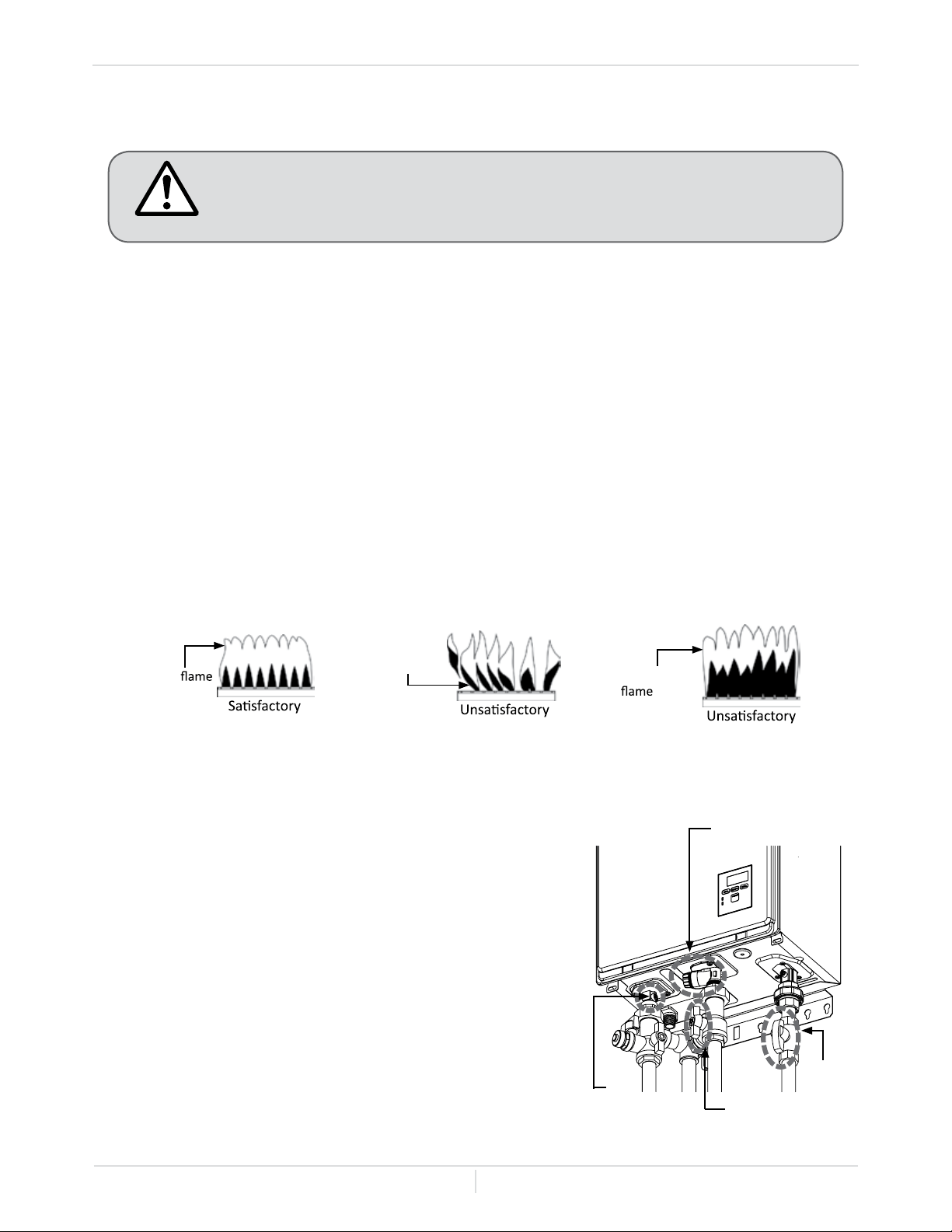
Owner's Guide
Page
47
Normal Operation
-MAINTENANCE AND SERVICE-
-UNIT DRAINING-
Turn off the electrical power supply and close the manual gas shutoff valve
and the manual water control valve before servicing.
• Be sure that all openings for combustion and ventilation air are not blocked.
• The venting system should be checked annually for any leaks, corrosion, blockages or damage.
• The burner should be checked annually for dust, lint, grease or dirt.
• Keep the area around the micro-boiler clear. Remove any combustible materials, gasoline or any
ammable vapors and liquids.
• In accordance with all local codes and common safety practices, water discharged from the
pressure relief valve can cause severe burns instantly from scalding. DO NOT touch the pressure
relief valve.
• If the relief valve discharges periodically, it may be due to thermal expansion in a closed water
supply system. Contact the water supplier or local plumbing inspector on how to correct this
situation.
• Visual check of burner ames (see below) through the burner window in the burner assembly
located at the middle of the micro-boiler.
The manufacturer recommends having the micro-boiler checked once a year or as necessary by a
licensed technician. If repairs are needed, any repairs should be done by a licensed technician.
1. Close the manual gas shutoff valve.
2. Turn off power to the micro-boiler and wait a couple of
seconds. Turn on again.
3. Wait 30 seconds, and then turn off power to the micro-
boiler, yet again.
4. Close the water shutoff valve.
5. Have a bucket or pan to catch the water from the micro-
boiler's drain plugs. Unscrew the small drain plug rst
and unscrew the large drain plug next to drain all the
water out of the micro-boiler.
6. Wait a few minutes to ensure all water has completely
drained from the micro-boiler.
WARNING
Water valve
Gas
valve
Drain plug
(Small)
Drain plug
(Large)
Flame
blowing up
Blue
Red or Yellow
Owner's Guide
Page
48
Troubleshooting
TROUBLESHOOTING
-General-
PROBLEM SOLUTIONS
TEMPERATURE and AMOUNT OF HOT WATER
The water is not hot enough.
• Compare the ow and temperature. See the chart on p. 58.
• Is the plumbing correct(primary/secondary, pump size, ect.)?
• Is the gas supply valve fully open? (p. 33)
• Is the gas line sized properly? (p. 24)
• Is the gas supply pressure sufcient? (p. 20 and p. 25)
• Is the set temperature set too low? (p. 43 to p. 45)
The water is too hot. • Is the set temperature set too high? (p. 43 to p. 45)
The hot water is not available
when there is a call for heat.
• Make sure the unit has 120VAC, 60Hz power supply.
• Is the temperature controller power button turned on?
• Is the gas supply valve fully open? (p. 33)
• Is the Y-strainer clean?
• Can the emitters sufciently draw at least 0.5GPM (1.9 L/min)
through the micro-boiler. (p. 43)
• Is the unit frozen? (p. 46)
• Is there enough gas in the tank/cylinder? (For Propane)
• Is it plumbed backwards with reverse plumbing?
The hot water turns cold and
stays cold.
• Is the ow rate enough to keep the unit running? (p. 43)
• Is the gas supply valve fully open? (p. 33)
• Is the Y-strainer clean?
• Is the system clean of debris and obstructions?
Fluctuation in hot water
temperature.
• Is the gas line sized properly? (p. 24)
• Is the supply gas pressure sufcient? (p. 20 and p. 25)
• Is the plumbing correct?
WATER HEATER
Unit does not ignite when
water goes through the unit.
• Is the power on the micro-boiler?
• Is the gas on?
• Is the ow rate over 0.5GPM (1.9 L/min)? (p. 43)
• Is the system Y-strainer clean?
• Check for reverse connection and cross connection. (p. 30)
• Is the temperature controller power button on?(p. 43 & p. 44)
• Check if the system return temperature is to high?
The fan motor is still spinning
after operation has stopped.
• This is normal. After operation has stopped, the fan motor keeps
running from 15 to 70 seconds in order to re-ignite quickly, as well
as purge all the exhaust gas out of the ue.
Abnormal sounds from the
micro-boiler.
• Is the correct gas type of micro-boiler installed? (LP or NG)
• Are the DIPswitch settings for your altitude set correctly?(p. 29)
• Check the ame quality. (p. 47)
• Is the intake or exhaust vent blocked? (p. 10)
• Is the vent length and diameter correct? (p. 11 to p. 16)
• Is the manifold pressure set correctly? (p. 4)
Unit sounds abnormal while in
operation
• Contact the manufacturer at 1-763-331-3066
REMOTE
CONTROLLER
Controller does not display
anything when the power
button is turned on.
• Make sure the micro-boiler is supplied with power.
• Make sure the connection to the micro-boiler is correct.
• Note: When the micro-boiler has not operated for ve minutes or
more, the display of the controller turns off to conserve energy.
An ERROR code is displayed. • Please see "-ERROR CODES-" on page 49.
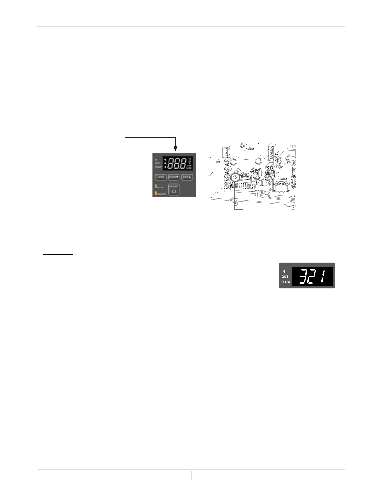
Owner's Guide
Page
49
Troubleshooting
-ERROR CODES-
-General-
• The micro-boiler has self-diagnostics for safety and convenience when troubleshooting.
• If there is a problem with the micro-boiler itself, or the installation of the unit, the error code will be
displayed on the temperature controller.
• Consult with the table on the following pages for the description of each error code.
• Indicator on the controller: "321" will be displayed on the screen in its
entirety.
• Green LED on the computer board: The green LED on the computer
board will be blinking two times.
Green LED
Error code indicator on the temperature
controller
Error code
Example: If your unit has the "321" error code (which signies an inlet thermistor failure)
Owner's Guide
Page
50
Display
Green
LED
Malfunction
Description
Diagnosis
031
One Time
Incorrect DIPswitch
setting
• Check the DIPswitch settings on the PCB (Part #701).
101
Five
Times
Warning for the "991"
error code
• Check if the gas type of the micro-boiler matches the gas
supplied to it.
• Check if there is any blockage in the intake air and/or
exhaust.
• If the micro-boiler is installed as a direct-vent system,
check whether there is enough distance between the
intake air terminal and the exhaust terminal.
• Check the altitude/elevation of area where the micro-
boiler is installed and match the appropriate DIPswitches.
• Check if there is grease and/or dirt in the burner (Part
#101) and the fan motor (Part #103), especially if the
micro-boiler has been installed in a contaminated area.
• Check if the DIPswitches match gas type of the micro-
boiler.
• Check the manifold pressure at Max. and Min.
• Check combustion chamber tube (Part #117) to make
sure it is clear and securely installed.
111
Three
Times
Ignition failure
• Check if the Hi-limit switch (Part #411) is properly
functioning.
• Check for connection/breakage of wires (Part
#412,707,708,709,710), burn marks on the computer
board (Part #701), and/or soot on the ame rod
(Part#108).
• Check if there is a buzzing spark ignition sound coming
from the burner (Part #101) when micro-boiler prepares
for combustion.
• Listen for the double "clunk" sound coming from gas valve
assembly (Part #102) when the micro-boiler goes into
combustion.
• Check if there is leaking from heat exchanger (Part #401).
• Check that the gas is turned on.
• Check gas supply.
121
Three
Times
Loss of ame
• Check if the Hi-limit switch (Part #411) is properly
functioning.
• Check for connection/breakage of wires (Part
#412,707,708,710), burn marks on the computer board
(Part #701), and/or soot on the ame rod (Part #108).
• Check if there is leaking from heat exchanger (Part #401).
• Check gas supply.
311
Two Times
Outlet thermistor
failure
• Check for connection/breakage of wires and/or debris on
thermistor (Part #407,408,715).
• Check the resistance.
321
Two Times Inlet thermistor failure
341
Two Times
Exhaust thermistor
failure
-Fault Analysis of Error Codes-
Troubleshooting
If an error code is displayed on the computer board of the micro-boiler and/or on the temperature
controller, please check the following. After checking, consult with the manufacturer.
Owner's Guide
Page
51
Troubleshooting
Display
Green
LED
Malfunction
Description
Diagnosis
391
Two
Times
Air-Fuel ratio rad
failure
• Check for connection/breakage of wires (Part #708)
and/or soot on the AFR rod (Part #108).
510
Six Times
Abnormal main gas
solenoid valve
• Check for connection/breakage of wires (Part #707)
and/or burn marks on the computer board (Part #701).
• Check for signs of vent corrosion.
• Check gas valve contacts and gas valve wire harness
connections for signs of rust or corrosion.
551
Six Times
Abnormal gas
solenoid valve
• Check for connection/breakage of wires (Part #707)
and/or burn marks on the computer board (Part #701).
• Check gas valve contacts and gas valve wire harness
connections for signs of rust or corrosion.
611
Four
Times
Fan motor fault
• Check for connection/breakage of wires, dust buildup
in the fan motor (Part #103) and/or burn marks on the
computer board (Part #701).
• Check for frozen/corrosion of connectors (Part #103).
701
One Time
Computer board
fault
• Check for connection/breakage of wires (Part #711).
711
One Time
Gas solenoid valve
drive circuit failure
• Refer to the 111 and 121 error codes.
721
Six Times
False ame
detection
• Check if there is a leaking from heat exchanger (Part
#401).
751
N/A
Miscommunication
between micro-boiler
and temperature
controller
• Inspect the connections between the micro-boiler and
temperature controller.
• Check the power supply of the micro-boiler.
941
Five
Times
Abnormal exhaust
temperature
• Check to see if the exhaust temperature is higher than
149°F (65°C).
991
Five
Times
Imperfect
combustion
• Check if the gas type of the micro-boiler matches the
gas supplied to it.
• Inspect the environment around the micro-boiler.
Determine how long the micro-boiler has been installed
and match DIPswitches.
• Check the altitude/elevation of the area of where the
micro-boiler is installed.
• Check if there is any blockage in the intake air and/or
exhaust.
• If the micro-boiler is installed as a direct-vent system,
check whether there is enough distance between the
intake air terminal and the exhaust terminal.
• Check if there is grease and/or dirt in the burner (Part
#101) and the fan motor (Part #103), especially if the
micro-boiler has been installed in a contaminated area.
• Check the DIPswitches match gas type of the micro-
boiler.
• Check the manifold pressure at Max. and Min.
• Check combustion chamber tube (Part #117) to see if it
is clear and securely installed.
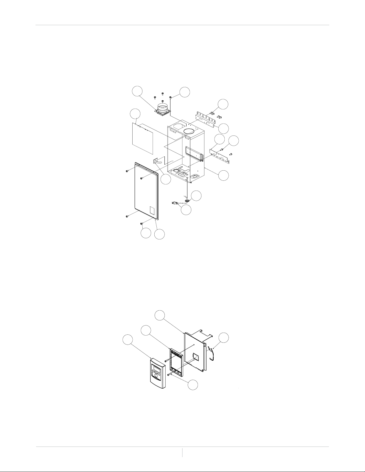
Owner's Guide
Page
52
Components Diagram
COMPONENTS DIAGRAM
-Case assembly-
-Temperature controller-
722
721
056
721
724
702
704
052
052
052
004
004
001
007
003
050
002
714
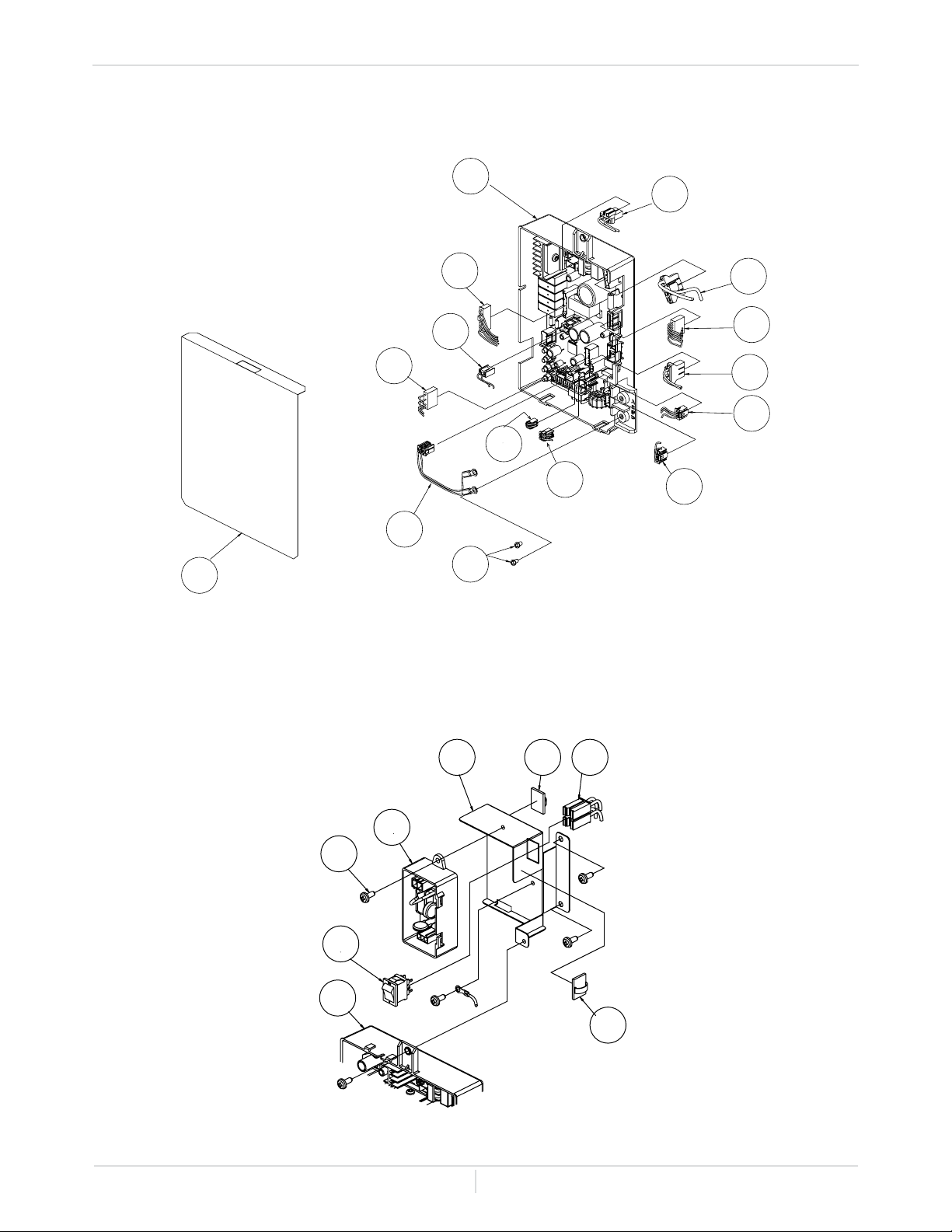
Owner's Guide
Page
53
Components Diagram
-Computer board assembly-
-Surge box assembly-
709
710
103
708
402
707
701
711
716
402
407
408
060
713
706
701
710
703
120
053
705
712
712
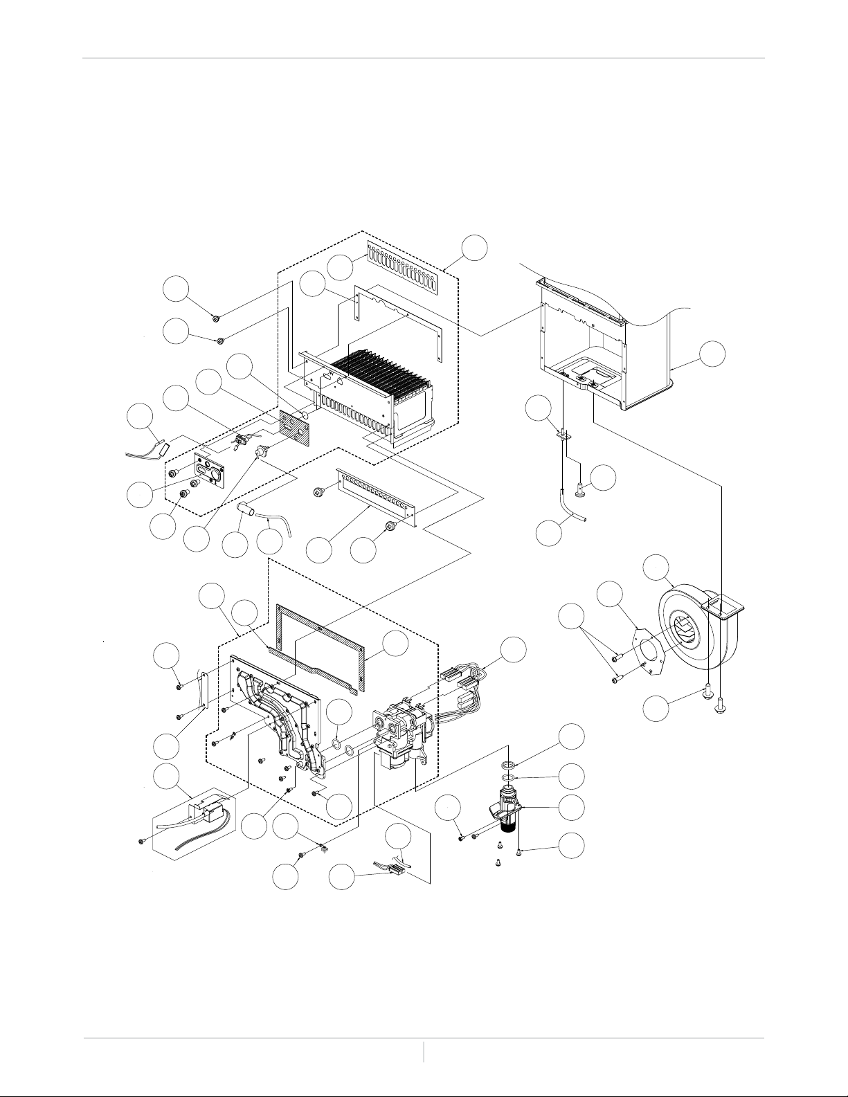
Owner's Guide
Page
54
Components Diagram
-Burner assembly-
101
401
116
053
117
103
105
064
054
104
115
053
053
106
107
108
708
110
061
109
111
709
112 053
114
113
707
102
053
120
709
150
057
055 062
053 711
117
055
119
151
118
051
Manifold
assembly
Burner assembly
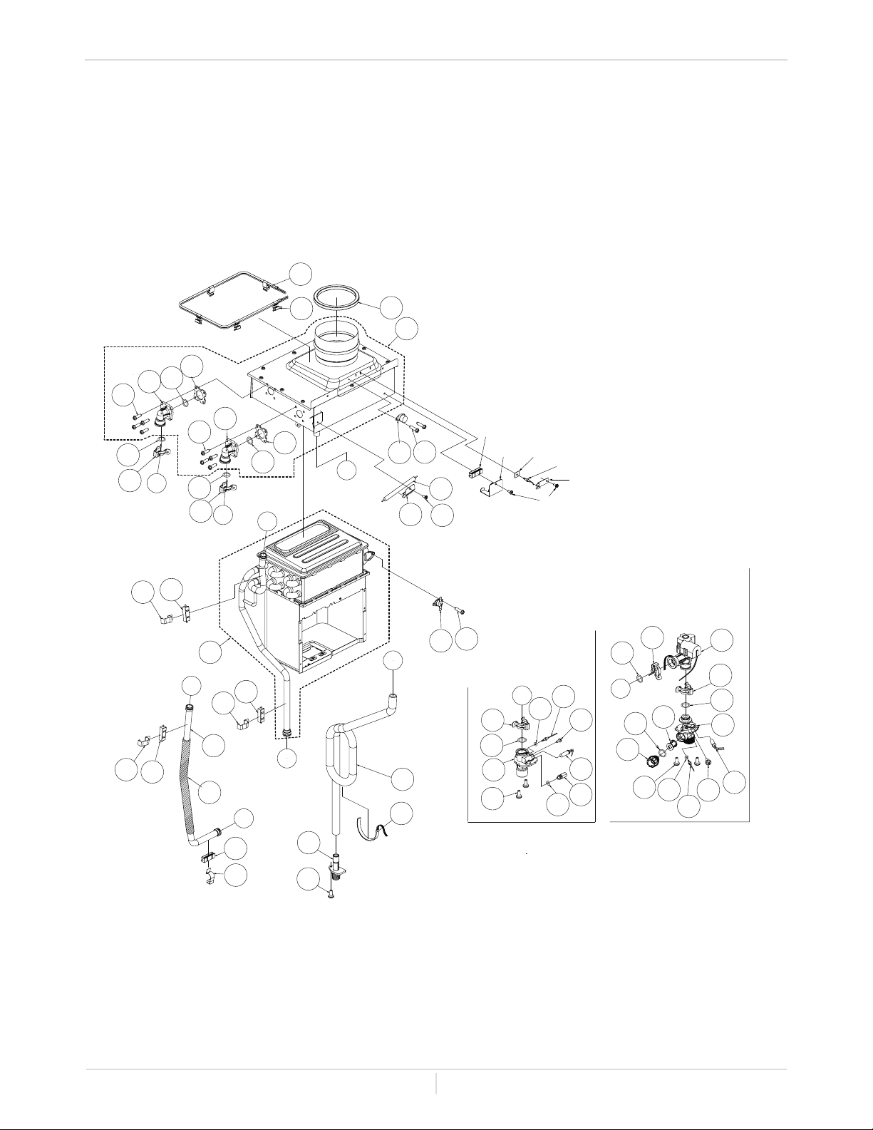
Owner's Guide
Page
55
Components Diagram
-Water way assembly-
C
D
D
C
461
452
412
417
466 064
411
058
413
450
053
415
403
052
467
463
063
455
458
462
413
451
451
413
451
414
414
451
052
409
457
460
453
408
059
454
410
416
455
458
402
459
457
404
406
456
405
052
453
407
059
416
A
B
A
B
401
154
E
E
467
463
063
455
458
455
455
468
418
419 465
715
464
053
Owner's Guide
Page
56
Parts List
PARTS LIST
Item # Description Part #
001 Case assembly EK450
002 Front cover EK452
003
004
005
006
007
Intake air port assembly
Bracket
Junction box
Power supply cord assembly
Back guard panel
EK454
EK455
EK190
EK456
EK457
050
051
052
053
Screw M4 x 12 (W / Washer)
Screw M4 x 10 (W / Washer)
Screw M4 x 10 (Coated)
Screw M4 x 10
EW000
EW001
EW002
EW003
054
055
056
057
Hex head screw M4 x 12 (W / Washer)
Hex head screw M4 x 8
Pan screw M4 x 20
Tap tight screw M4 x 12 FEZN
EW004
EW005
EW018
EKK31
058
059
060
Screw M3 x 6 SUS
Screw M4 x 6
Screw M3 x 6
EW00A
EW009
EK191
061
062
063
064
Pan screw M4 x 8
Wire clamp 60
Screw M4 x 10
Screw M3 x 6 SUS3
EW00D
EM167
EW00P
EW00B
101
102
Burner assembly
Manifold with gas valve assembly LP
Manifold with gas valve assembly NG
EK458
EK459
EK460
103 Fan motor EK109
104
105
106
107
Burner gasket
Fan damper
Burner window
Rod holder gasket
EKK2X
EK491
EKK2V
EKK2W
108
109
110
111
Flame rod
Igniter rod
Rod holder
Rod cap
EK193
EK461
EKK32
EK462
112
113
114
115
Burner damper
Manifold gasket A
Manifold gasket B
Burner holder gasket
EK463
EKK2Y
EKK2K
EKK0G
116
117
118
119
Pressure port
Combustion chamber tube
Gas inlet
Gas inlet ring
EKK2D
EX019
EK465
EKK2Z
120 Surge box plate EK466
Owner's Guide
Page
57
Parts List
Item # Description Part #
150
151
154
O-ring P18 NBR (Black)
O-ring P20 NBR (Black)
Silicon ring
EZP18
EK042
EKN50
401 Heat exchanger assembly EK467
402
403
404
405
406
Flow adjustment valve / Flow sensor
Condensate drain port
Water inlet
Inlet drain plug
Inlet water lter
EK129
EKH23
EKK1U
EKK2B
EKK2C
407 Inlet thermistor EKK4J
408 Outlet thermistor EK207
409
410
Water outlet
Outlet drain plug
EK104
EKK2E
411 Hi-Limit switch EM212
412
413
Overheat-cut-off fuse
Pipe heater
EX02A
EK468
414 Inlet heater EK469
415
416
Drain tube
Inlet heater
EK470
EK105
417 Secondary heat exchanger EK471
418
419
Secondary heat exchanger heater
Heater xing plate
EK473
EK474
450
451
452
Pipe heater xing plate
Heater xing plate 16
Fuse xing plate
EK475
EK031
EK476
453
454
455
456
457
O-ring P4 FKM
O-ring P6 FKM
O-ring P14 FKM
O-ring P15 FKM
O-ring P16 FKM
EZF04
EZF06
EZF14
EZF15
EZF16
458
459
Fastener "14-22"
Fastener "16A"
EKK24
EM192
460
461
Fastener "16-25A"
Flat heater
EKK39
EK217
462 Cold pipe for 140 model EK477
463
464
Header connection
Thermistor xing plate
EK478
EX13H
465
466
467
468
Exhaust thermistor gasket
Hi-limit switch for exhaust
Gasket
Inlet pipe packing
EX13L
EKH6G
EK229
EK479
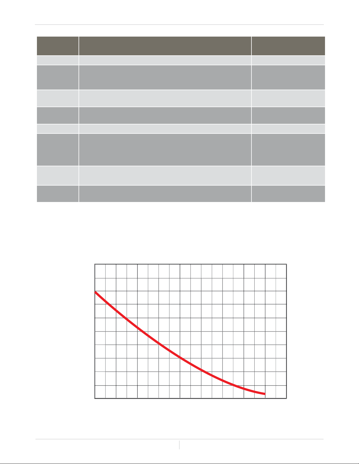
Owner's Guide
Page
58
Parts List
Item # Description Part #
701 Computer board EK480
702
703
704
Rubber grommet
Surge box
120 VAC wire
EX148
EK280
EK146
705
707
120 VAC Power ON-OFF switch
Gas valve wire
EKK4V
EK482
708
709
Flame rod wire
Igniter assembly
EK483
EK484
710 Freeze protection thermostat EKJ59
711
712
713
714
Proportional gas valve wire
Nylon clamp FC6
Computer board cover
Cable clamp
EK112
EX004
EKK1M
EX13C
715
716
Exhaust thermistor
Exhaust Hi-limit switch wire
EKH6E
EK180
721
722
Temperature controller
Fixing plate
EK487
EK490
OUTPUT TEMPERATURE CHART
Chart is based on properly sized gas line.
3
4
5
6
7
8
Boiler Flow-GPM
100 110 120 130 140
Boiler Temp vs Flow Rate with 70 Deg F Return Fluid
DEG F

Owner's Guide
Page
59
1. The manufacturer warrants this product against defects in materials or workmanship as described
in this document if installed within the United States or Canada. The manufacturer or its authorized
Service Representative will, at its sole discretion, repair or replace any failed or defective
mechanical or electrical parts, or components thereof, or, if the manufacturer or its authorized
Service Representative cannot replace said parts and repair is not commercially practicable,
the manufacturer or its authorized Service Representative will refund the purchase price. The
manufacturer or its authorized Service Representative may, at its sole discretion, use new,
refurbished or reconditioned parts.
2. Warranty for all models:
• All warranty claims must be authorized and approved by the manufacturer.
3. General terms of limited warranty:
• This limited warranty gives you specic legal rights, and you may also have other rights which
vary from State to State. The manufacturer will honor the warranty to the original retail buyer at
the original location only, within the United States or Canada, and it is not transferable.
• THIS WARRANTY COVERS ONLY FAILED MECHANICAL AND ELECTRICAL PARTS DUE
TO FACTORY DEFECTS UNDER NORMAL USAGE FOR THE PRODUCT'S INTENDED
PURPOSES AND WITHIN THE APPLICABLE PERIOD SPECIFIED IN THE TABLES
ABOVE. ONLY DIRECT DAMAGES SHALL BE RECOVERABLE BY A CLAIMANT
UNDER THIS LIMITED WARRANTY AND, IN NO EVENT, WHETHER AS A RESULT OR
BREACH OF CONTRACT, BREACH OF WARRANTY, TORT LIABILITY (INCLUDING
NEGLIGENCE), STRICT LIABILITY, INDEMNITY OR OTHERWISE WILL BE LIABLE FOR
ANY SPECIAL, INCIDENTAL, OR INDIRECT CONSEQUENTIAL DAMAGES INCLUDING
PROPERTY DAMAGE, PERSONAL DAMAGES, LOSS OF USE, OR INCONVENIENCE.
SOME STATES DO NOT ALLOW THE EXCLUSION OR LIMITATION OF INCIDENTAL OR
CONSEQUENTIAL DAMAGES, SO THE ABOVE LIMITATION MAY NOT APPLY TO YOU.
4. Limitation on Duration of Implied Warranties:
• ANY IMPLIED WARRANTIES ARISING UNDER STATE LAW, INCLUDING THE IMPLIED
WARRANTIES OF FITNESS FOR A PARTICULAR PURPOSE AND MERCHANTABILITY,
SHALL IN NO EVENT EXTEND PAST THE EXPIRATION OF ANY WARRANTY PERIOD
HEREUNDER. SOME STATES DO NOT ALLOW LIMITATIONS ON HOW LONG AN
IMPLIED WARRANTY LASTS, SO THE ABOVE LIMITATION MAY NOT APPLY TO YOU.
5. THIS WARRANTY WILL NOT COVER THE FOLLOWING:
• Any product that is not installed by a licensed plumber, gas installer, or contractor.
• Damages due to accidents, abuse, misuse, improper installation, misapplication, or incorrect
sizing.
• Damages due to res, ooding, freezing, electrical surges, or any Acts of God.
• Damages due to unauthorized alterations, attachments, and/or repairs.
• Damages due to a lack of maintenance (e.g. Y-stainer, water treatment system, vent blockage,
ect.).
• Any product installed in an improper environment (e.g. corrosive, dusty, chemically
contaminated, excessive lint, etc.).
Warranty
LIMITED WARRANTY
Application Type Heat Exchanger Parts Labor
Single Family Residential Heating 5 2 N/A

Owner's Guide
Page
60
Warranty
• Freeze damage that occurs without taking proper preventive measures as described in the
installation manual.
• Condensate damage due to improperly installed or lack of a condensate trap (drain).
• Any product not installed in compliance with all applicable local & provincial codes, ordinances,
and good trade practices.
• Any product sold to or installed in areas outside of the fty states (and the District of Columbia) of
the United States of America and Canada.
• Any product installed in applications that cause the micro-boiler to activate more than 300 times
per day. (This averages to an activation every 5 minutes in a 24-hour period.)
• Damages due to improper installation:
• Gas: incorrect gas pipe sizing, incorrect gas meter sizing, incorrect gas type, and/or gas
pressures that fall outside the product's specied range.
• Water: incorrect water pipe sizing, water pressures that fall outside the product's specied
range, recirculation ow rates that fall outside the product's specied range (air removal), and/
or lack of proper methods of air removal in a closed-loop, circulation system. (See installation
manual for details.)
• Electric: supply power voltages that fall outside the product's specied range.
• Damages due to water quality:
• Introduction of liquids other than water or water / glycol mixtures into the product.
• Introduction of pool water, spa water, or any chemically treated water into the product.
• Introduction of hard water measuring more than 7 grains per gallon (120 ppm) for single
family domestic applications or more than 4 grains per gallon (70 ppm) for all other types of
applications into the product.
• Introduction of untreated or poorly treated well water into the product.
• Introduction of water with pH levels less than 6.5 and greater than 8.5 into the product.