Loading ...
Loading ...
Loading ...
Device features
-
12
-
Owner’s Manual
Tio1608-D
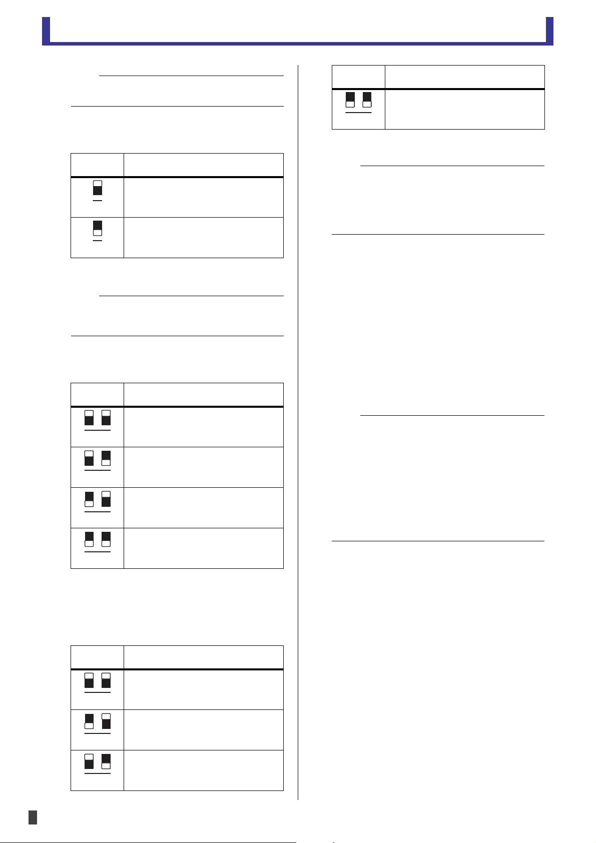
• Switch 4 (Dante SECONDARY port mode)
This switch determines the operating mode of the
[SECONDARY] Dante connector.
When Quick Config is used, these switches are
disabled.
• Switches 5 and 6 (IP address mode)
These switches determine how the unit's IP address is
set.
• Switches 7 and 8 (start up mode)
These switches determine how the unit starts up
during start up mode. When set to "refresh" mode,
the settings of the mixer are applied when the unit
starts up. When set to "resume" mode, the unit
returns to the same state as the last time it was used.
When Quick Config is used, the "normal operation"
mode settings are disabled.
4 [PRIMARY] and [SECONDARY] Dante connectors
etherCON CAT5 connector that connects the unit to a
Dante device, such as a NY64-D digital audio interface
card. When DIP switch 4 is set to the daisy-chain
connection position (i.e., up position), signals
received on one connector are sent out via the other
connector. When DIP switch 4 is set to the redundant
connection position (i.e., down position), the
[SECONDARY] connector functions as a backup and
carries the same signals as the [PRIMARY] connector. If
for some reason signals cannot be carried over the
[PRIMARY] connector (for example, because the cable
becomes damaged or disconnected, or because the
network switch malfunctions), the unit switches to
the [SECONDARY] connector.
5 [LINK/ACT] indicators
Indicate the status of the signals carried by the
[PRIMARY] and [SECONDARY] connectors. If an
indicator is flashing quickly, the corresponding
Ethernet cable is not connected properly.
6 [1G] indicators
Indicate the connection status of the PRIMARY and
SECONDARY connectors. If an indicator is lit, the
corresponding connector is connected to a Gigabit
Ethernet network.
NOTE
If switches 7 and 8 are set to the "update mode" or "diagnostic
mode" positions, the unit will not be reset.
Switch
position
[SECONDARY] connector operating
mode
Daisy chain connection
Redundant connection
NOTE
When the Switch 4 is set to "Redundant connection", the
head amp control function (page 14) is only available via
the [PRIMARY] Dante connector.
Switch
position
IP address mode
Auto (link local)
DHCP
Static IP Auto (192.168.0.ID)
Static IP Manual
The IP address is specified from an
external device such as R Remote V3.
Switch
position
Start up mode
Refresh mode (normal operation)
Resume mode (normal operation)
Update mode
4
4
5 6
5
6
5 6
5 6
7
8
7 8
7
8
Diagnostic mode
NOTE
• Update mode and diagnostic mode are used when
performing maintenance on the unit. Normally you will not
use these modes.
• Update mode and diagnostic mode can be enabled even
when using Quick Config. Normally you will not use these
modes.
NOTE
• To avoid electromagnetic interference, use shielded
twisted-pair (STP) cables that are rated at CAT5e or higher.
Use conductive tape or comparable means to make sure
that the metal parts of the cable plugs are electrically
connected to the STP cable shield.
• We recommend using RJ-45 plugs that are compatible with
Neutrik etherCON CAT5 connectors. You can also use
cables with standard RJ-45 plugs.
• The maximum length of cable that can be used varies
depending on the type of cable. When using CAT5e cables,
data can be sent between devices that are connected by up
to 100 m of cable.
Switch
position
Start up mode
7 8
Loading ...
Loading ...
Loading ...