
3844-UG4088E-E.indd 13844-UG4088E-E.indd 1 11/18/2022 6:50:11 AM11/18/2022 6:50:11 AM

2 —
®
MACHINIST CALC
®
PRO 2
The Machinist Calc
®
Pro 2 Advanced Machining Math +
Materials calculator (Model 4088) provides hundreds of fast,
precise machining-specific solutions for turning, drilling, boring
and face, end and slot milling. Built-in tables for 20 materials, 6
processes and 3 tools will let you spend much less time looking
up your most-needed calculations on charts, in books or on the
Internet and more time machining.
The Machinist Calc Pro 2 gives you hundreds of calculations,
including:
• Speeds and Feeds
• Built-in Drill and Thread Size reference tables
• Drill Point Cut Depth solutions
• Bolt Pattern hole layouts with center x, y coordinates
• Right triangle math
• Trigonometric solutions
• Wire Sizes and 3-Wire Measurements
Work in and convert between U.S. and Metric units, including:
• Decimal Inches/Mils
• Feet-Inch-Fractions
• m, mm, cm
• Area, Volume and Weight
TABLE OF CONTENTS
GETTING STARTED .................................................................4
KEY DEFINITIONS ..................................................................4
Basic Function Keys .............................................................5
Dimensional Function Keys ..................................................5
Weight and Volume Function Keys ....................................... 7
Trigonometric Function Keys ................................................7
Miscellaneous Function Keys ...............................................8
Machinist Function Keys ....................................................... 8
MEMORY OPERATION .........................................................13
3844-UG4088E-E.indd 23844-UG4088E-E.indd 2 11/18/2022 6:50:11 AM11/18/2022 6:50:11 AM

User's Guide — 3
USING THE MACHINIST CALC PRO 2 .................................15
U.S./METRIC MODES ...........................................................15
MATERIALS, PROCESSES AND TOOLS .............................15
Materials .............................................................................15
Processes ...........................................................................16
Tools ...................................................................................17
RPM (SPINDLE SPEED) .......................................................17
RPM – Basic .......................................................................17
RPM – Face Milling ............................................................18
RPM – End Milling ..............................................................19
FEED RATE – IPM ................................................................. 20
Feed Rate – Based on Cutting Feed and RPM
(for Turning) ........................................................................21
Feed Rate – Based on Cutting Feed and RPM
(for Drilling) .........................................................................21
Feed Rate – Based on Feed per Tooth, RPM and
# of Teeth ............................................................................22
Feed Rate – End Milling .....................................................23
CUTTING SPEED - SFM .....................................................25
Cutting Speed – Turning .....................................................25
Cutting Speed – End Milling ...............................................26
Cutting Speed – Drilling ......................................................27
FEED PER TOOTH/CHIP LOAD - IPT ..................................28
Feed per Tooth – Based on Cutting Feed and # of Teeth ...28
Feed per Tooth – Based on Feed Rate, RPM and
# of Teeth ............................................................................29
Feed per Tooth – Face Milling ............................................29
CUTTING FEED – IPR ......................................................... 31
Cutting Feed – Based on Feed per Tooth and # of Teeth ... 31
Cutting Feed – Based on Feed Rate and RPM ..................32
Cutting Feed – Turning .......................................................33
DRILL SIZES ........................................................................34
Numeric Drill Size Entry ...................................................... 34
Letter Drill Size Entry ..........................................................35
Inch Drill Size Entry ............................................................36
Millimeter Drill Size Entry .................................................... 37
DRILL POINT ........................................................................37
THREAD SIZING .................................................................. 38
INTERNAL THREAD ............................................................39
3844-UG4088E-E.indd 33844-UG4088E-E.indd 3 11/18/2022 6:50:11 AM11/18/2022 6:50:11 AM

4 —
®
EXTERNAL THREAD ...........................................................40
THREAD CLASSIFICATION ...............................................40
Changing Thread Classes ..................................................41
Changing a U.S. Thread Classification ...............................41
Changing a Metric Thread Classification ............................41
Numeric Thread Size ..........................................................43
Fractional Thread Size........................................................45
Metric Thread Size ..............................................................47
Custom Thread Percentage................................................49
WIRE SIZES AND 3-WIRE MEASUREMENTS .................50
Wire Size ............................................................................50
3-Wire Measurement – Known Thread Size and
Wire Size ............................................................................51
Pitch Diameter – Known 3-Wire Measurement
and Wire Size .....................................................................52
BOLT PATTERN .....................................................................54
Bolt Pattern .........................................................................54
RIGHT TRIANGLE FUNCTIONS ........................................56
Right Triangle – Based on Adjacent and Opposite Legs ....56
Right Triangle – Based on Hypotenuse and Angle .............57
CIRCLE CALCULATIONS ...................................................58
Circumference and Area – Based on Diameter ..................58
BASIC D:M:S AND TRIGONOMETRY EXAMPLES ..........58
Converting Degrees:Minutes:Seconds ...............................58
Time Calculations Using D:M:S ..........................................59
Trigonometric Functions .....................................................59
APPENDIX A – MATERIAL TABLES ...................................61
APPENDIX B – DEFAULT SETTINGS ...............................64
APPENDIX C – PREFERENCE SETTINGS ......................65
APPENDIX D – BASIC FUNCTIONS .................................70
APPENDIX E – ACCURACY/ERRORS,
AUTO SHUT-OFF, BATTERIES, RESET ............................76
GETTING STARTED
KEY DEFINITIONS
You may want to practice getting a feel for your calculator
keys by reading through the key definitions and learning how
to enter data, how to store values, etc., before proceeding to
the examples.
3844-UG4088E-E.indd 43844-UG4088E-E.indd 4 11/18/2022 6:50:11 AM11/18/2022 6:50:11 AM

User's Guide — 5
Basic Function Keys
O
Turns on power. Pressing once
clears the last entry and the display. Pressing twice
clears all non-permanent values.
gO
Turns all power o. Clears all non-
permanent values.
+-*
,=
Arithmetic operation keys
0-9
and .
Keys used for entering numbers.
g
Used with the dimensional keys to
convert between units or with other keys to access
special functions.
gr
Used for storing values.
gr
1-9
Used to
store values in memory registers 1 through 9.
r
Used with other keys to recall stored
values and settings.
rr
Clears Accumulative Memory
and displays total.
M
Adds displayed value to
Accumulative Memory.
gM
M- — Subtracts displayed value from
Accumulative Memory.
Dimensional Function Keys
m
Identies entry as
millimeters, with repeated presses toggling
between linear, area and volume units.
Also converts dimensional value to units of
millimeters, with repeated presses toggling
between millimeters and meters.
3844-UG4088E-E.indd 53844-UG4088E-E.indd 5 11/18/2022 6:50:11 AM11/18/2022 6:50:11 AM

6 —
®
g5
Identies entry as
centimeters, with repeated presses toggling
between linear, area and volume units.
g9
Identies entry as meters, with
repeated presses toggling between linear, area
and volume units.
g7
Identies entry as Feet, with repeated
presses of g7 toggling between linear,
area and volume units. Also used with i and
/ for entering Feet-Inch values. Repeated
presses of g7 during conversions toggle
between Feet-Inch-Fractions and decimal Feet.
i
Identies entry as Inches, with
repeated presses toggling between linear,
area and volume units. Entry can be whole
or decimal numbers. Also used with /
for entering fractional Inch values (e.g.,
9i1/2). Repeated presses during
conversions toggle between fractional and
decimal Inches.
/
Used to enter fractions.
Fractions can be entered as proper (1/2, 1/8,
1/16) or improper (3/2, 9/8). If the denominator
(bottom) is not entered, the calculator's
fractional accuracy setting is automatically
used. Results are always shown in typical
dimensional fractional format.
B
Multiplies a dimensionless
entry by 0.001 Inch and displays the result
as Inches. Converts a linear entry to decimal
Inches. For both methods, the result is rounded
and displayed to three decimal places.
3844-UG4088E-E.indd 63844-UG4088E-E.indd 6 11/18/2022 6:50:11 AM11/18/2022 6:50:11 AM

User's Guide — 7
g5
Identies entry as
centimeters, with repeated presses toggling
between linear, area and volume units.
g9
Identies entry as meters, with
repeated presses toggling between linear, area
and volume units.
g7
Identies entry as Feet, with repeated
presses of g7 toggling between linear,
area and volume units. Also used with i and
/ for entering Feet-Inch values. Repeated
presses of g7 during conversions toggle
between Feet-Inch-Fractions and decimal Feet.
i
Identies entry as Inches, with
repeated presses toggling between linear,
area and volume units. Entry can be whole
or decimal numbers. Also used with /
for entering fractional Inch values (e.g.,
9i1/2). Repeated presses during
conversions toggle between fractional and
decimal Inches.
/
Used to enter fractions.
Fractions can be entered as proper (1/2, 1/8,
1/16) or improper (3/2, 9/8). If the denominator
(bottom) is not entered, the calculator's
fractional accuracy setting is automatically
used. Results are always shown in typical
dimensional fractional format.
B
Multiplies a dimensionless
entry by 0.001 Inch and displays the result
as Inches. Converts a linear entry to decimal
Inches. For both methods, the result is rounded
and displayed to three decimal places.
Weight and Volume Function Keys
g6
Enters or converts a weight or volume
value to tons.
g4
Enters or converts a weight or
volume value to pounds.
g3
Enters or converts a
weight or volume value to metric tons.
g2
Enters or converts a weight or
volume value to grams.
g1
Enters or converts a weight
or volume value to kilograms.
g0
Stores a new
weight per volume as pounds per cubic foot or
other format as shown below. Default value is
490 pounds per cubic foot of steel.
● Pounds per cubic foot
● Pounds per cubic inch
● Metric tons per cubic meter
● Kilograms per cubic meter
Trigonometric Function Keys
ga
Sine — Calculates the Sine of an entered
degree or unitless value.
gm
Calculates the angle for the entered
or calculated Sine value.
go
Calculates the Cosine of an entered
degree or unitless value.
gi
Calculates the angle
for the entered or calculated Cosine value.
gh
Calculates the Tangent of an
entered degree or unitless value.
3844-UG4088E-E.indd 73844-UG4088E-E.indd 7 11/18/2022 6:50:12 AM11/18/2022 6:50:12 AM

8 —
®
g/
Calculates the angle
for the entered or calculated Tangent value.
Miscellaneous Functions
g.
Converts between D:M:S and decimal degree
formats; repeated presses will toggle between
the two formats.
%
Used to nd a given percent of a
number.
g%
x
2
— Squares the value on the display.
A
Used to delete entries
one keystroke at a time (unlike the O
function, which deletes the entire entry).
gA !Calculates the Square
Root of the number on the display.
g,
Finds the Reciprocal of a
number (e.g., 8g,= 0.125).
g*
Returns all stored values to the
default settings. Does not aect Preference
Settings.
g-
Toggle displayed value
between negative and positive value.
g+
Pi — Displays value of
π (3.1415927).
g=
Accesses
various customizable settings, such as
dimensional answer formats
(see section).
Machinist Function Keys
Unitless entries are assumed to be inches in U.S. mode,
millimeters in Metric mode.
3844-UG4088E-E.indd 83844-UG4088E-E.indd 8 11/18/2022 6:50:12 AM11/18/2022 6:50:12 AM

User's Guide —
d
Enters a Diameter. Calculates circle
Area and Circumference given entered Diameter.
gd
Enters the number of holes in a
Bolt Pattern. Calculates the hole Center-to-Center
Spacing and the x and y coordinates for each
hole in a Bolt Pattern given entered Diameter,
Number of Bolt Holes, Starting Angle (optional)
and Center x and y coordinates.
N
Scrolls through 20 Material types.
Materials are assigned numbers from 1-20,
which can be used to select a particular Material.
Materials are used to determine tabular Feed and
Speed values. See Materials section on page 16
for the complete list of available materials.
gN
Enters a Cut Depth for
use in determining tabular Feed and Speed values,
as well as Material Removal Rate.
P
Scrolls through six Processes:
1. Face Milling (default) 4. Turning
2. End Milling 5. Boring
3. Slot Milling 6. Drilling
Used to determine tabular Feed and Speed
values. Assigned number can be used to select a
particular Process.
gP
Enters a Cut Width for
use in determining tabular Feed and Speed values,
as well as Material Removal Rate and Radial
Chip Thinning Adjustment Factor.
L
Scrolls through three Tool Types:
1. High Speed Steel (default)
2. Carbide
3. High Performance
Used to determine tabular Feed and Speed
values. Assigned number can be used to select a
particular Tool Type.
3844-UG4088E-E.indd 93844-UG4088E-E.indd 9 11/18/2022 6:50:12 AM11/18/2022 6:50:12 AM

—
®
gL
Enters a Cut Length to
calculate Cut Time.
S
Enters or calculates
Cutting Speed. Unitless entries are assumed to
be Feet in U.S. mode, meters in Metric mode.
Calculates Cutting Speed given entered Diameter
and RPM. Provides tabular Cutting Speed based
on Process, Material, Tooling, Depth of Cut, Width
of Cut and Diameter.
gS
Wire Size — Enters or calculates Wire Size
for 3-Wire Measurements. Calculates the
recommended Ideal, Maximum and Minimum
Wire Sizes given an entered Thread Size.
R
Enters or
calculates RPM (Spindle Speed). Calculates
RPM given entered Diameter and Cutting
Speed. Result is displayed as a whole number.
gR
Enters or
calculates a Three-Wire Measurement. Calculates
the minimum and maximum Three-Wire
Measurements and Pitch Diameters given entered
Thread Size and Wire Size, assuming an External
thread type. If a Three-Wire Measurement value
is entered, the Pitch Diameter calculation is based
on this entered measurement.
T
Enters or calculates
Chipload or Feed per Tooth (IPT), the chip size
of material cut by each tooth. Typically used in
Milling operations. Automatically adjusts for Radial
Chip Thinning, if applicable, when Process is set
to Face or End Milling. Provides tabular Feed per
Tooth based on Process, Material, Tooling, Depth
of Cut, Width of Cut and Diameter.
3844-UG4088E-E.indd 103844-UG4088E-E.indd 10 11/18/2022 6:50:12 AM11/18/2022 6:50:12 AM

User's Guide —
gT
Enters or
calculates Cutting Feed or Feed per Revolution
(IPR). Provides tabular Feed per Revolution
based on Process, Material, Tooling and Depth
of Cut.
I
Enters or calculates Feed
Rate or Feed per Minute (IPM). When applicable,
also provides Material Removal Rate and Cut
Time.
gI
Enters the Number
of Teeth on a tool. Default value is 1.
D
Enters a numeric, letter, fractional or
metric Drill Size, displaying the decimal Inch (U.S.
mode) or millimeter (Metric mode) equivalent of the
Drill Size. The nearest Drill Size is displayed if the
entered value doesn't match a Drill Size. Repeated
presses of D or + scroll through Drill Sizes in
increasing order. Presses of - scroll through Drill
Sizes in decreasing order. Selected Drill Size is
stored upon exiting function.
gD
Enters the Cutting Angle of a
Drill Point. Calculates the Drill Point Cut Depth
that needs to be taken into account when it's
necessary to maintain a specic full diameter
depth.
gn
Enters a non-standard Thread
Grip Percentage for use in determining screw Tap
Drill Sizes. Default value is 75%.
t
Enters a numeric, fractional
or metric Thread Size and provides Thread
characteristics such as Cut Tap Drill Size,
Minimum Major Diameter, etc. See
section for further details on entry format,
valid entries and a listing of the resulting Thread
characteristics.
3844-UG4088E-E.indd 113844-UG4088E-E.indd 11 11/18/2022 6:50:12 AM11/18/2022 6:50:12 AM

—
®
gt
Used
to select the Thread Class for numeric and
fractional Threads and the Tolerance Class for
metric Threads. The default Class for numeric and
fractional Thread Sizes is 2B (Internal) and the
default Tolerance Class for metric Thread Sizes
is 6H (Internal). See section for
further details on available Classes.
g8
Enters alphabet character selection
mode. While in this mode, a letter can be selected
and used with D to enter a letter Drill Size.
Entering this mode with a unitless entry between
1 and 26 will display the corresponding letter of
the alphabet (i.e., 5g8 displays the letter
E). While in Alpha mode, presses of 8 or +
scroll forward through the alphabet, while presses
of - scroll backward.
a
Enters or calculates the Adjacent
(horizontal) leg of a right triangle. Calculates
Adjacent value given two other right-triangle
values. Also enters the Center x-coordinate of a
Bolt Pattern.
o
Enters or calculates the
Opposite (vertical) leg or height of a right triangle.
Calculates Opposite value given two other
right-triangle values. Also enters the Center
y-coordinate of a Bolt Pattern.
h
Enters or calculates the
Hypotenuse (diagonal) of a right triangle.
Calculates Hypotenuse value given two other
right-triangle values.
3844-UG4088E-E.indd 123844-UG4088E-E.indd 12 11/18/2022 6:50:12 AM11/18/2022 6:50:12 AM

User's Guide —
n
Enters or calculates an Angle,
providing the Adjacent Angle for both instances.
Calculates an Angle given two other right-triangle
values. Also enters Lead Angle adjustment for
Face Milling, as well as Starting Angle of the
rst hole of a Bolt Pattern, with 0° being the
three oʼclock position and the rotation going
counterclockwise.
MEMORY OPERATION
Whenever the M key is pressed, the displayed value will be
added to the Memory. Other Memory functions:
FUNCTION KEYSTROKE
Add to Memory M
Subtract from Memory gM
Recall total in Memory rM
Display/Clear Memory rr
Memory is semi-permanent, clearing only when you do one of
the following:
— turn o the calculator
— press rr
— press g* (Clear All).
When Memory is recalled (rM), consecutive presses of
M will display the calculated Average and total Count of the
accumulated values.
Using M+
355M
M+
& 355.
(cont'd)
3844-UG4088E-E.indd 133844-UG4088E-E.indd 13 11/18/2022 6:50:12 AM11/18/2022 6:50:12 AM

—
®
255M
M+
& 255.
745gM (M-)
M-
& 745.
rM
TOTAL VALUE
M+
& - 135.
M
AVERAGE VALUE
M+
& - 45.
M
TOTAL ENTRIES
M+
& 3.
rr
M+
- 135.
Using Memory Storage Keys (M1- M9)
In addition to the standard cumulative Memory (as previously
described), your calculator has nine independent Storage
Registers – M1 through M9 – that can be used to permanently
store single, noncumulative values. The following example
shows the use of M1 (gr1). To use M2 - M9, replace
the presses of the 1 key with presses of the corresponding
number key (2-9).
You can replace a value in one of these Memory registers by
storing a new value in place of the stored value.
FUNCTION KEYSTROKE
Store single value in M1 gr1
Clear M1 0gr1
Recall M1 r1
Store 175 into M1, recall the value, and then clear the value:
(cont'd)
3844-UG4088E-E.indd 143844-UG4088E-E.indd 14 11/18/2022 6:50:12 AM11/18/2022 6:50:12 AM

User's Guide —
255M
M+
& 255.
745gM (M-)
M-
& 745.
rM
TOTAL VALUE
M+
& - 135.
M
AVERAGE VALUE
M+
& - 45.
M
TOTAL ENTRIES
M+
& 3.
rr
M+
- 135.
Using Memory Storage Keys (M1- M9)
In addition to the standard cumulative Memory (as previously
described), your calculator has nine independent Storage
Registers – M1 through M9 – that can be used to permanently
store single, noncumulative values. The following example
shows the use of M1 (gr1). To use M2 - M9, replace
the presses of the 1 key with presses of the corresponding
number key (2-9).
You can replace a value in one of these Memory registers by
storing a new value in place of the stored value.
FUNCTION KEYSTROKE
Store single value in M1 gr1
Clear M1 0gr1
Recall M1 r1
Store 175 into M1, recall the value, and then clear the value:
175gr1
MEMORY
M-Ø1 175.
gOO 0.
r1
MEMORY
M-Ø1 175.
0gr1
MEMORY
M-Ø1 0.
USING THE
U.S. AND METRIC MODE SETTINGS
The Machinist Calc Pro 2 allows you to set the calculator to
use either U.S. Mode or Metric Mode. The default setting is
U.S. units. You can change to Metric Mode by changing your
Preference setting (see page 65). The examples in this User's
Guide are done in U.S. Mode.
MATERIALS, PROCESSES AND TOOLS
Materials
The Machinist Calc Pro 2 has 20 built-in Material types that
can be used to determine tabular Feed and Speed values.
You can scroll through the available Materials by repeatedly
pressing the N key, or by pressing the + key or -
key to scroll forward and backward through the Materials.
You can also enter the assigned number (see listing on next
page), then press the N key to select the Material, which
will be set until you select another Material or perform a Clear
All (g*).
0. No Material (Default)
1. 1020 Low-Carbon Steel
2. 1045 Medium-Carbon Steel
3. 1060 High-Carbon Steel
(cont'd)
3844-UG4088E-E.indd 153844-UG4088E-E.indd 15 11/18/2022 6:50:12 AM11/18/2022 6:50:12 AM

—
®
4. 4140 Chromium-Molybdenum Alloy Steel
5. 4340 Nickel-Chromium-Molybdenum Alloy Steel
6. 52100 Chromium Alloy Steel
7. 304 Austenitic Stainless Steel
8. 316 Austenitic Stainless Steel
9. 410 Martensitic Stainless Steel
10. 430 Ferritic Stainless Steel
11. P20 Mold Type Tool Steel
12. H13 Hot Work Tool Steel
13. 2024-T3 Wrought Aluminum Alloy
14. 6061-T6 Wrought Aluminum Alloy
15. A390.0-T5 Cast Aluminum Alloy
16. Ti-6Al-4V Alpha-Beta Titanium Alloy
17. Ti-10V-2Fe-3Al Beta Titanium Alloy
18. Alloy 718 Nickel-Based Heat Resistant Alloy
19. Alloy X Nickel-Based Heat Resistant Alloy
20. Haynes Alloy 188 Cobalt-Based Heat Resistant Alloy
There is a Workpiece Materials Conversion Table in Appendix A.
Processes
The Machinist Calc Pro 2 has six built-in Processes that can be
used to determine tabular Feed and Speed values.
You can scroll through the available Processes by repeatedly
pressing the P key, or by pressing the + key or - key to
scroll forward and backward through the Processes.
You can also enter the assigned number (see following page),
then press the P key to select the Process, which will be set
until you select another Process or perform a Clear All (g*).
(cont'd)
3844-UG4088E-E.indd 163844-UG4088E-E.indd 16 11/18/2022 6:50:12 AM11/18/2022 6:50:12 AM

User's Guide —
1. Face Milling (Default) 4. Turning
2. End Milling 5. Boring
3. Slot Milling 6. Drilling
Tools
The Machinist Calc Pro 2 has three built-in Tool Types that can
be used to determine tabular Feed and Speed values.
You can scroll through the available Tool Types by repeatedly
pressing the L key, or by pressing the + key or - key to
scroll forward and backward through the Tools.
You can also enter the assigned number (see listing below),
then press the L key to select the Tool Types, which will
be set until you select another Tool or perform a Clear All
(g*).
1. High Speed Steel (Default)
2. Carbide
3. High Performance
RPM
(
SPINDLE SPEED
)
RPM is the rotational speed of the spindle in revolutions per
minute. In a milling machine or drill, the Spindle Speed is the
rotation of the attached cutting tool. In a turning machine, it is
the rotation of the attached workpiece. RPM can be calculated
given values for Diameter and Cutting Speed.
RPM -
Calculate the RPM when milling with a 0.375" bit at a Cutting
Speed of 300 sfm (surface feet per minute):
OO 0.
1. Enter the bit Diameter:
(cont'd)
3844-UG4088E-E.indd 173844-UG4088E-E.indd 17 11/18/2022 6:50:12 AM11/18/2022 6:50:12 AM

—
®
.375d
DIAMETER
0.375 INCH
2. Enter the Cut Speed:
300S
CUT SPEED
/MIN 300. FEET
3. Calculate the Spindle Speed (RPM):
R
RPM
3056.
RPM –
Find the Spindle Speed when milling 1060 Hi-Carbon Steel (3)
with a 0.5" High Performance bit (3) at a Depth of Cut of 0.25":
1. Clear the calculator:
OO
0.
2. Set Process to Face Milling:
1P
FACE MILLING
1.
3. Set Tooling to High Performance:
3L
HIGH PERFORMANCE
TOOL 3.
4. Set Material to 1060 Hi-Carbon Steel:
3N
1060-HI C. STEEL
MATL 3.
5. Enter Depth of Cut:
.25gN (DOC)
DEPTH OF CUT
0.25 INCH
6. Enter Tool Diameter:
(cont'd)
3844-UG4088E-E.indd 183844-UG4088E-E.indd 18 11/18/2022 6:50:12 AM11/18/2022 6:50:12 AM

User's Guide —
.5d
DIAMETER
0.5 INCH
7. Calculate RPM:
R
RPM
4584.
8. Show tabular Cut Speed:
R
CUT SPEED
/MIN 600. FEET
9. Now, change the Depth of Cut to 0.1" and nd new RPM
and tabular Cut Speed:
.1gN (DOC)
DEPTH OF CUT
0.1 INCH
R
RPM
6875.
R
CUT SPEED
/MIN 900. FEET
RPM –
Find the Spindle Speed when milling 316 Stainless Steel with
a 1" 4-uted Uncoated Carbide bit at a 0.5" radial Width of Cut.
Then, change the Depth of Cut to 0.25" and recalculate:
1. Clear the calculator:
OO
0.
2. Set Process to End Milling:
2P
END MILLING
2.
3. Set Tooling to Carbide:
2L
CARBIDE TOOL
2.
3844-UG4088E-E.indd 193844-UG4088E-E.indd 19 11/18/2022 6:50:12 AM11/18/2022 6:50:12 AM

—
®
4. Set Material to 316 Stainless Steel (selection #8):
8N
316-AUS. S. STEEL
MATL 8.
5. Enter Width of Cut:
.5gP (WOC)
WIDTH OF CUT
0.5 INCH
6. Enter Tool Diameter:
1d
DIAMETER
1. INCH
7. Calculate RPM:
R
RPM
802.
8. Show tabular Cut Speed:
R
CUT SPEED
/MIN 210. FEET
9. Now, change Width of Cut to 0.25" and nd new RPM and
tabular Cut Speed:
.25gP (WOC)
WIDTH OF CUT
0.25 INCH
R
RPM
859.
R
CUT SPEED
/MIN 225. FEET
FEED RATE
-
IPM
Feed Rate (IPM) is the speed of the cutting tool's movement
relative to the workpiece as the tool makes a cut. You can
calculate Feed Rate given values for RPM and either Feed per
Tooth (IPT) and number of teeth for Milling operations, or Feed
per Revolution (IPR) for all other machine operations.
3844-UG4088E-E.indd 203844-UG4088E-E.indd 20 11/18/2022 6:50:12 AM11/18/2022 6:50:12 AM

User's Guide —
Feed Rate –
Calculate the Feed Rate if you are turning a 1" steel round
stock down using a Cutting Feed of 0.031 Inches per
Revolution and a rotational speed of 900 RPM:
OO
0.
1. Enter the Feed per Revolution:
.031gT (IPR)
FEED/REV.
0.031 INCH
2. Enter the RPM:
900R
RPM
900.
3. Calculate the Feed Rate:
I
FEED/MINUTE
27.900 INCH
Feed Rate – )
Calculate the Feed Rate for a Drilling operation that is using a
recommended Cutting Feed of 0.004 Inches per Revolution at
800 RPM:
OO 0.
1. Enter the Cutting Feed:
4BgT (IPR)
FEED/REV.
0.004 INCH
2. Enter the RPM:
800R
RPM
800.
3. Calculate the Feed Rate:
(cont'd)
3844-UG4088E-E.indd 213844-UG4088E-E.indd 21 11/18/2022 6:50:12 AM11/18/2022 6:50:12 AM
22 —
®
I
FEED/MINUTE
3.200 INCH
Feed Rate –
Calculate the Feed Rate for a four-uted end mill using a Feed
per Tooth (Chip Load) of 0.005" turning at 1,000 RPM:
RPM: 1000
Feed
Rate
Feed per Tooth:
0.005″
Number
of Teeth: 4
g* ALL CLEARED 0.
1. Enter the Feed per Tooth:
5BT
FEED/TOOTH
0.005 INCH
2. Enter the Number of Teeth:
4gI (#Teeth)
NUMBER OF TEETH
4.
3. Enter the RPM:
1000R
RPM
1000.
4. Calculate the Feed Rate:
I
FEED/MINUTE
20.000 INCH
(cont'd)
3844-UG4088E-E.indd 223844-UG4088E-E.indd 22 11/18/2022 6:50:12 AM11/18/2022 6:50:12 AM

User's Guide — 23
(cont'd)
Feed Rate –
For End Milling (2), nd the Feed Rate (IPM) using 1020
Low-Carbon Steel (1) and a 4-Tooth High Speed Steel Tool
(1) with a Diameter of 0.5", a 0.25" Width of Cut and a 20"
Length of Cut. Then, change the Width of Cut to 0.15" to
show the Adjusted Feed per Tooth and the RCT Adjustment
Factor. Then, add a 0.125" Depth of Cut and nd the Material
Removal Rate, Spindle Power and Spindle Torque:
g* ALL CLEARED 0.
1. Select the Process:
2P
END MILLING
2.
2. Select the Tool:
1L
HIGH SPEED STEEL
TOOL 1.
3. Select the Material:
1N
1020-LO C. STEEL
MATL 1.
4. Enter the # of Teeth:
4gI (#Teeth)
NUMBER OF TEETH
4.
5. Enter the Width of Cut:
.25gP (WOC)
WIDTH OF CUT
0.25 INCH
6. Enter the Length of Cut:
20gL (LOC)
LENGTH OF CUT
20. INCH
3844-UG4088E-E.indd 233844-UG4088E-E.indd 23 11/18/2022 6:50:12 AM11/18/2022 6:50:12 AM

24 —
®
7. Enter the Diameter:
.5d
DIAMETER
0.5 INCH
8. Calculate the Feed Rate:
I
FEED/MINUTE
3.667 INCH
9. Calculate the Cut Time:
I
CUT TIME
MIN 5.454
10. Calculate the RPM:
I
RPM
917.
11. Change the Width of Cut (Radial Chip Thinning
Adjustment):
.15gP (WOC)
WIDTH OF CUT
0.15 INCH
12. Recalculate Feed Rate, Cut Time and RPM:
I
FEED/MINUTE
9.336 INCH
I
CUT TIME
MIN 2.142
I
RPM
1070.
13. Show Adjusted Feed per Tooth and RCT Adjustment
Factor:
I
FEED/TOOTH
ADJ. 0.002 INCH
(cont'd)
3844-UG4088E-E.indd 243844-UG4088E-E.indd 24 11/18/2022 6:50:12 AM11/18/2022 6:50:12 AM

User's Guide — 25
I
RCT. ADJ. FACTOR
1.091
14. Now, add a 0.125" Depth of Cut and nd the Material
Removal Rate, Spindle Power and Spindle Torque:
.125gN (DOC)
DEPTH OF CUT
0.125 INCH
I
FEED/MINUTE
9.336 INCH
I
MATERIAL REMOVAL
/MIN 0.175 CU INCH
I
SPINDLE POWER
HP 0.123
I
SPINDLE TORQUE
LBFT 0.602
CUTTING SPEED
-
SFM
Cutting Speed (SFM) is the speed of the workpiece surface
relative to the edge of the cutting tool during a cut, typically
measured in Surface Feet per Minute. You can calculate
Cutting Speed by entering the Diameter of the tool or material
you're using and the RPM (Spindle Speed).
Cutting Speed –
Calculate the Cutting Speed when turning a 4" rod running at
300 RPM:
OO
0.
1. Enter the Diameter of the rod:
4d
DIAMETER
4. INCH
2. Enter the RPM:
(cont'd)
3844-UG4088E-E.indd 253844-UG4088E-E.indd 25 11/18/2022 6:50:12 AM11/18/2022 6:50:12 AM

26 —
®
300R
RPM
300.
3. Calculate the Cutting Speed:
S
CUT SPEED
/MIN 314. FEET
Cutting Speed –
Find the Cutting Speed when End Milling (2) using 1060-High
Carbon Steel (3) using a High Performance 0.5" bit (3) and
0.1" radial Width of Cut:
OO
0.
1. Select the Process:
2P
END MILLING
2.
2. Select the Tooling:
3L
HIGH PERFORMANCE
TOOL 3.
3. Select the Material:
3N
1060-HI C. STEEL
MATL 3.
4. Enter the Width of Cut:
.1gP (WOC)
WIDTH OF CUT
0.1 INCH
5. Enter the Diameter:
.5d
DIAMETER
0.5 INCH
6. Find the Cutting Speed:
(cont'd)
3844-UG4088E-E.indd 263844-UG4088E-E.indd 26 11/18/2022 6:50:12 AM11/18/2022 6:50:12 AM

User's Guide — 27
(cont'd)
S
CUT SPEED
/MIN 370.
7. Calculate the RPM:
S
RPM
2827.
Cutting Speed –
Find the Cutting Speed for Drilling (6) 1020-Low Carbon
Steel (1) with a 0.5" HSS (1) drill:
g*
ALL CLEARED 0.
1. Select the Process:
6P
DRILLING
6.
2. Select the Tooling:
1L
HIGH SPEED STEEL
TOOL 1.
3. Select the Material:
1N
1020-LO C. STEEL
MATL 1.
4. Enter the Drill Size:
.5D
1/2" DRILL
SIZE 0.500 INCH
5. Find the Cutting Speed:
S
CUT SPEED
/MIN 85. FEET
6. Calculate the Spindle Speed:
S
RPM
649.
3844-UG4088E-E.indd 273844-UG4088E-E.indd 27 11/18/2022 6:50:12 AM11/18/2022 6:50:12 AM

28 —
®
7. Change the Material to 1060-High Carbon Steel and
recalculate:
3N
1060-HI C. STEEL
MATL 3.
S
CUT SPEED
/MIN 65. FEET
S
RPM
497.
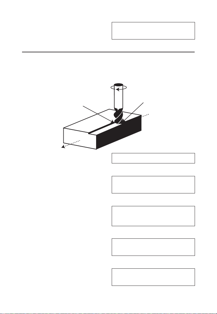
FEED PER TOOTH/CHIP LOAD
-
IPT
Feed per Tooth (IPT), or Chip Load, is the distance that the
workpiece feeds into each tooth on a multi-point cutting tool
as it rotates. You can calculate Feed per Tooth given values
for Number of Teeth and Cutting Feed (IPR). If the Cutting
Feed is not known, the Feed per Tooth can be calculated
given values for Number of Teeth, Feed Rate (IPM) and
RPM (Spindle Speed).
Feed per Tooth –
Calculate Feed per Tooth (IPT) with a Cutting Feed (IPR) of
0.024" for 4 Teeth:
g*
ALL CLEARED 0.
1. Enter the Cutting Feed:
.024gT (IPR)
FEED/REV.
0.024 INCH
2. Enter the Number of Teeth:
4gI (#Teeth)
NUMBER OF TEETH
4.
3. Calculate the Feed per Tooth:
T
FEED/TOOTH
0.006 INCH
(cont'd)
3844-UG4088E-E.indd 283844-UG4088E-E.indd 28 11/18/2022 6:50:12 AM11/18/2022 6:50:12 AM

User's Guide —
(cont'd)
Feed per Tooth –
Calculate Feed per Tooth (IPT) with a Feed Rate (IPM) of
12.8" per Minute, 4 Teeth and a Spindle Speed of 775 RPM:
OO
0.
1. Enter the Feed Rate:
12.8I
FEED/MINUTE
12.8 INCH
2. Enter the Number of Teeth:
4gI (#Teeth)
NUMBER OF TEETH
4.
3. Enter the RPM:
775R
RPM
775.
4. Calculate the Feed per Tooth:
T
FEED/TOOTH
0.004 INCH
Feed per Tooth –
Find the Feed per Tooth (IPT) for Face Milling (2) using
4140-Alloy Steel for Material (4) and a 2-uted High Speed
Steel Tool (1) with a Diameter of 1" and a 0.1" Depth of Cut.
Then, add a 0.15" Width of Cut and 45º Lead Angle:
g*
ALL CLEARED 0.
1. Select the Process:
1P
FACE MILLING
1.
2. Select the Tool:
3844-UG4088E-E.indd 293844-UG4088E-E.indd 29 11/18/2022 6:50:12 AM11/18/2022 6:50:12 AM

—
®
1L
HIGH SPEED STEEL
TOOL 1.
3. Select the Material:
4N
4140-ALLOY STEEL
MATL 4.
4. Enter the Number of Teeth:
2gI (#Teeth)
NUMBER OF TEETH
2.
5. Enter the Depth of Cut:
.1gN (DOC)
DEPTH OF CUT
0.1 INCH
6. Enter the Diameter:
1d
DIAMETER
1. INCH
7. Find the Feed per Tooth and other values:
T
FEED/TOOTH
0.012 INCH
T
FEED/MINUTE
12.376 INCH
T
NUMBER OF TEETH
2.
T
RPM
516.
8. Now, add a Width of Cut to 0.15" and a 45° Lead Angle and
recalculate:
.15gP (WOC)
WIDTH OF CUT
0.15 INCH
(cont'd)
3844-UG4088E-E.indd 303844-UG4088E-E.indd 30 11/18/2022 6:50:12 AM11/18/2022 6:50:12 AM

User's Guide —
45 n
ANGLE
(Ө) 45.°
T
FEED/TOOTH
ADJ.
0.024 INCH
T
FEED/MINUTE
24.508 INCH
T
NUMBER OF TEETH
2.
T
RPM
516.
T
RCT. ADJ. FACTOR
1.400
T
LEAD ANGLE ADJ.
1.414
CUTTING FEED
–
IPR
Cutting Feed is the distance the cutting tool or workpiece
advances during one revolution of the spindle, typically
measured in Inches per Revolution (IPR). You can calculate
Cutting Feed given values for the Feed per Tooth or Chip Load
(IPT) and Number of Teeth. If these values are unknown, you
can calculate Cutting Feed with Feed Rate (IPM) and RPM
(Spindle Speed).
Cutting Feed –
Calculate the Cutting Feed (IPR) with a Feed per Tooth (IPT)
of 0.005" and 4 Teeth:
g*
ALL CLEARED 0.
1. Enter the Feed per Tooth:
(cont'd)
3844-UG4088E-E.indd 313844-UG4088E-E.indd 31 11/18/2022 6:50:13 AM11/18/2022 6:50:13 AM

32 —
®
.005T
FEED/TOOTH
0.005 INCH
2. Enter the Number of Teeth:
4gI (#Teeth)
NUMBER OF TEETH
4.
3. Calculate the Cutting Feed:
gT (IPR)
FEED/REV.
0.020 INCH
Cutting Feed –
Calculate the Cutting Feed (IPR) using a 15" Feed Rate (IPM)
and a Spindle Speed of 800 RPM:
OO 0.
1. Enter the Feed Rate:
15I
FEED/MINUTE
15. INCH
2. Enter the Spindle Speed:
800R
RPM
800.
3. Calculate the Cutting Feed:
gT (IPR)
FEED/REV.
0.019 INCH
(cont'd)
3844-UG4088E-E.indd 323844-UG4088E-E.indd 32 11/18/2022 6:50:13 AM11/18/2022 6:50:13 AM

User's Guide — 33
Cutting Feed –
Find the Cutting Feed (IPR) when Turning (4) 1", 1020
Low-Carbon Steel (1) at a 0.1" Depth of Cut using a High
Speed Steel (1) bit:
g* ALL CLEARED 0.
1. Select the Process:
4P
TURNING
4.
2. Select the Material:
1N
1020-LO C. STEEL
MATL 1.
3. Select the Tool:
1L
HIGH SPEED STEEL
TOOL 1.
4. Enter the Depth of Cut:
.1gN (DOC)
DEPTH OF CUT
0.1 INCH
5. Enter Diameter:
1d
DIAMETER
1. INCH
6. Find the Cutting Feed:
gT (IPR)
FEED/REV.
0.015 INCH
3844-UG4088E-E.indd 333844-UG4088E-E.indd 33 11/18/2022 6:50:13 AM11/18/2022 6:50:13 AM

34 —
®
DRILL SIZES
The D key allows the selection of a desired Drill Size,
which can be entered as a:
● Numeric value (whole digits 1 through 97)
● Letter between A and Z
● Fractional or decimal Inch value (max. of 3-1/2")
● Millimeter value (max. of 78 mm).
The selected Drill Size is displayed along with its decimal Inch
equivalent. If the entered value doesn't match a Drill Size,
the nearest Drill Size is displayed. You can scroll through the
available sizes in increasing order with either the D key
or the + key. The - key displays the available sizes in
decreasing order. To set the displayed Drill Size, press O
(or any other key).
Numeric Drill Size Entry
Enter a #36 Drill and scroll through the next larger available sizes:
OO 0.
1. Enter the Drill Size:
36D
#36 DRILL
SIZE
0.107
INCH
2. Display the next larger available sizes:
D
2.75mm DRILL
SIZE 0.108 INCH
D
7/64" DRILL
SIZE 0.109 INCH
D*
#35 DRILL
SIZE 0.110 INCH
* Repeated presses of D display the next larger Drill Sizes. The
+ and - keys will scroll forward and backward, respectively,
through all available Drill Sizes.
3844-UG4088E-E.indd 343844-UG4088E-E.indd 34 11/18/2022 6:50:13 AM11/18/2022 6:50:13 AM

User's Guide — 35
(cont'd)
Letter Drill Size Entry
You can enter letter Drill Sizes by selecting an alphabet
character via Alpha Mode (g8) and then storing it using
the D key. The desired letter can be selected by scrolling
through Alpha Mode until the letter is reached or by specifying
the numerical order of the letter within the alphabet prior to
entering Alpha Mode. Both methods are shown below.
Select Drill Size E by scrolling through Alpha Mode. Then,
select Drill Size G by entering the numerical order of the letter
(the letter G is 7th in the alphabet):
OO 0.
1. Enter Alpha Mode:
g8 (Alpha)
ALPHA CHARACTER
A 1.
2. Scroll until the letter E is displayed:
8888
ALPHA CHARACTER
E 5.
3. Enter as Drill Size:
D
"E" DRILL
SIZE 0.250 INCH
4. View next larger available sizes:
D
6.40mm DRILL
SIZE 0.252 INCH
D
6.50mm DRILL
SIZE 0.256 INCH
D
"F" DRILL
SIZE 0.257 INCH
3844-UG4088E-E.indd 353844-UG4088E-E.indd 35 11/18/2022 6:50:13 AM11/18/2022 6:50:13 AM

36 —
®
5. Enter order of letter G and enter Alpha Mode:
7g8 (Alpha)
ALPHA CHARACTER
G 7.
6. Enter as Drill Size:
D*
"G" DRILL
SIZE 0.261 INCH
* Repeated presses of D display the next larger Drill Sizes. The
+ and - keys will scroll forward and backward, respectively,
through all available Drill Sizes.
Inch Drill Size Entry
Enter hole sizes of 0.3", 1" and 1-19/64". After entering each
size, scroll through the available sizes to view the next larger
and next smaller sizes:
OO 0.
1. Enter the 0.3" hole size and view next larger and next
smaller sizes:
.3iD
7.60mm DRILL
SIZE 0.299 INCH
D
"N" DRILL
SIZE 0.302 INCH
--
19/64" DRILL
SIZE 0.297 INCH
2. Enter the 1" hole size and view next larger and next smaller
sizes:
1iD
1" DRILL
SIZE 1.000 INCH
D
25.50mm DRILL
SIZE 1.004 INCH
--
63/64" DRILL
SIZE 0.984 INCH
(cont'd)
3844-UG4088E-E.indd 363844-UG4088E-E.indd 36 11/18/2022 6:50:13 AM11/18/2022 6:50:13 AM

User's Guide — 37
3. Enter the 1-19/64" hole size and view next larger and next
smaller sizes:
1i19/64D
1-19/64" DRILL
SIZE 1.297 INCH
D
33.00mm DRILL
SIZE 1.299 INCH
--
1-9/32" DRILL
SIZE 1.281 INCH
Millimeter Drill Size Entry
Enter a 5.7 mm hole size and scroll through the available sizes
to view the next larger and next smaller sizes:
OO 0.
1. Enter the hole size as millimeters:
5.7mD
5.70mm DRILL
SIZE 0.224 INCH
2. View next larger and next smaller sizes:
D
5.75mm DRILL
SIZE 0.226 INCH
--
#2 DRILL
SIZE 0.221 INCH
DRILL POINT
The Drill Point function calculates the Drill Point Cut Depth
(length) of the stored Drill Size. By default, the calculation
is based on a Cutting Angle of 118°. If a different Angle is
desired, it can be stored using the Drill Point function (for
example,
120gD stores 120°).
Find the Drill Point Cut Depth for a 1/2-Inch drill with a 118°
Cutting Angle. Then, find the Cut Depth using a 127° Angle:
(cont'd)
3844-UG4088E-E.indd 373844-UG4088E-E.indd 37 11/18/2022 6:50:13 AM11/18/2022 6:50:13 AM

38 —
®
OO 0.
1. Enter the Drill Size:
1/2D
75 DRILL
SIZE 0.500 INCH
2. Enter 118° Angle and calculate the Drill Point Cut Depth:
118gD (Drill Point)
DRILL POINT CUT
DPTH 0.150 INCH
D
DRILL CUT ANGLE
118.000°
D
1/2" DRILL
SIZE 0.500 INCH
3. Enter 127° Angle and calculate the Drill Point Cut Depth:
127gD
DRILL POINT CUT
DPTH 0.125 INCH
THREAD SIZING
The t key allows you to enter a numeric, fractional
or metric Thread Size and then scroll through the various
available Thread characteristics, as shown in the tables
provided later in this section.
When using the t
key, the first entry is considered the
Thread Size. Upon entering the Thread Size, the Threads per
Inch (TPI) or Pitch is required. If the entered Thread Size is a
standard size, continuous presses of the t key will toggle
through the available common TPI or Pitches.
Once the desired TPI/Pitch is reached, pressing O stores
the Thread Size. If the Thread Size you enter is not a standard
size or if you have a non-common TPI/Pitch, you will need to
directly enter the TPI/Pitch value, pressing t after entering
it in order to store the Thread Size.
(cont'd)
3844-UG4088E-E.indd 383844-UG4088E-E.indd 38 11/18/2022 6:50:13 AM11/18/2022 6:50:13 AM

User's Guide —
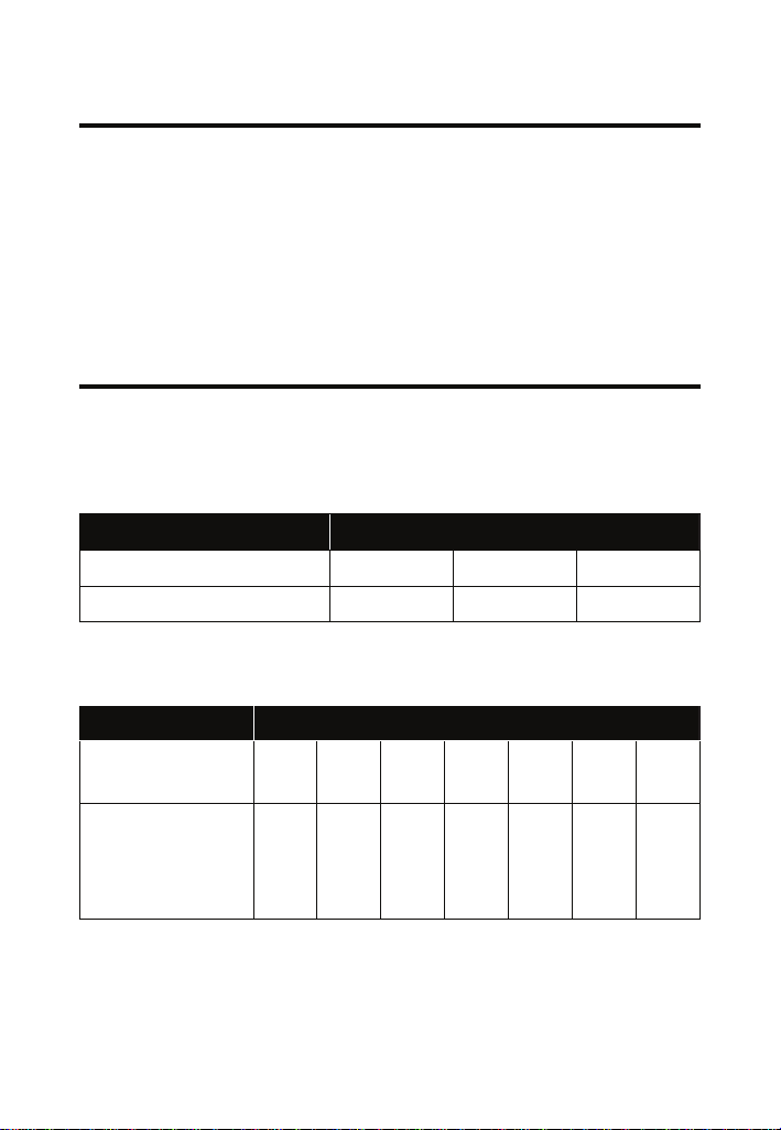
The following specifies the entry ranges that the calculator
allows for the Thread Size and TPI/Pitch values for numeric,
fractional and metric Thread Sizes:
Thread Size TPI/Pitch
Numeric 0, 1, 2, 3, 4, 5, 6, 8,
10, 12, 14
less than 100
Fractional 0.06" to 6" less than 100
Metric 1.6 mm to 300 mm less than or equal to 10
Entries outside of the ranges mentioned above will result in an
Entry Error.
The following tables list the available Thread characteristics
provided by the Thread Size function. Note that there are two
separate listings, one for Internal Threads and one for External
Threads. The listing shown within the Thread Size function
is determined by the set Thread Classification (see
section).
INTERNAL THREAD
Thread Size Minimum Pitch Diameter
Thread Pitch* Maximum Pitch Diameter
Cut Tap Drill Size** Minimum Minor Diameter
Roll Tap Drill Size** Maximum Minor Diameter
Close Fit Drill Size** Minimum Major Diameter
Free Fit Drill Size**
* Thread Pitch is only displayed for Numeric and U.S. Thread Sizes.
** If the resulting hole size is greater than 2 Inches or 50 mm, the
actual hole size will be displayed instead of adjusting to the closest
Drill Size.
3844-UG4088E-E.indd 393844-UG4088E-E.indd 39 11/18/2022 6:50:13 AM11/18/2022 6:50:13 AM
—
®
EXTERNAL THREAD
Thread Size Minimum Pitch Diameter
Thread Pitch* Maximum Major Diameter
Cut Rod Size Minimum Major Diameter
Roll Shank Size Maximum Minor Diameter
Maximum Pitch Diameter
* Thread Pitch is only displayed for Numeric and U.S. Thread Sizes.
THREAD CLASSIFICATION
With the Machinist Calc Pro 2 you can choose between
Internal and External Threads. Entering a U.S. Thread Size
will allow you to choose among U.S. Thread Classes as
shown below.
THREAD TYPE U.S. THREAD CLASSES
Internal 1B 2B* 3B
External 1A 2A 3A
Entering a Metric Thread will allow you to choose among
Metric Thread Tolerance Classes as shown below.
THREAD TYPE METRIC THREAD TOLERANCE CLASSES
Internal 3G
3H
4G
4H
5G
5H
6G
6H*
7G
7H
8G
8H
9G
9H
External
3g
3h
3e
3f
4g
4h
4e
4f
5g
5h
5e
5f
6g
6h
6e
6f
7g
7h
7e
7f
8g
8h
8e
8f
9g
9h
9e
9f
* Default settings
3844-UG4088E-E.indd 403844-UG4088E-E.indd 40 11/18/2022 6:50:13 AM11/18/2022 6:50:13 AM

User's Guide —
Changing Thread Classes
To display the current Thread Classification, press gt.
Repeated presses of t will toggle between External
and Internal Thread Types. You can change the number of
a Thread Class by entering the number of the desired class/
grade and pressing gt.
Changing a U.S. Thread Classification
g*
ALL CLEARED 0.
1. Recall the current Thread Classification:
gt (Thread Class)
U.S. INT. THREAD
2B 2.
2. Change to U.S. External Thread Class 2:
t
U.S. EXT. THREAD
2A 2.
3. Change to U.S. External Thread Class 1:
1gt (Thread Class)
U.S. EXT. THREAD
1A 1.
4. Change to U.S. Internal Thread Class 1:
t
U.S. INT. THREAD
1B 1.
Changing a Metric Thread Classification
Changing a Metric Thread Tolerance Class is done in the
same manner, with several selections available for Internal
and External Threads.
g*
ALL CLEARED 0.
1. Enter a Tolerance Grade of 4:
(cont'd)
3844-UG4088E-E.indd 413844-UG4088E-E.indd 41 11/18/2022 6:50:13 AM11/18/2022 6:50:13 AM

42 —
®
4gt (Thread Class)
MM INT. THREAD
4H
4.
2. Scroll through the available Tolerance Positions for the
entered Grade:
t
MM EXT. THREAD
4g 4.
t
MM EXT. THREAD
4h 4.
t
MM EXT. THREAD
4e 4.
t
MM EXT. THREAD
4f 4.
t
MM INT. THREAD
4G 4.
t
MM INT. THREAD
4H 4.
3. Enter a Tolerance Grade of 6 and scroll through the
available Tolerance Positions for the entered Grade:
6gt (Thread Class)
MM INT. THREAD
6H 6.
t
MM EXT. THREAD
6g 6.
t
MM EXT. THREAD
6h 6.
t *
MM EXT. THREAD
6e 6.
* Repeated presses of t will continue to scroll through the
available Tolerance Positions of the specified Grade.
The number 3 can be entered to select both U.S. and Metric
classes. To select either, go to Preferences and set the calculator to
either U.S. Mode or Metric Mode.
(cont'd)
3844-UG4088E-E.indd 423844-UG4088E-E.indd 42 11/18/2022 6:50:13 AM11/18/2022 6:50:13 AM

User's Guide — 43
Numeric Thread Size
Enter an 8-32 screw and scroll through the available Internal
Thread (Class 2B) characteristics, then switch to External
Thread (Class 2A) and scroll through the available Thread
characteristics:
The default U.S. Thread Class is 2B (Internal). To view the
current Thread Class, press gt. To change the class, press
t again.
Thread Size calculations for Pitch, Major, and Minor Diameter
attributes are compliant with ANSI/ASME B.1.1-2003 and ANSI/
ASME B.1.13M-2005.
g*
ALL
CLEARED
0.
1. Verify Thread Class is set to 2B:
gt (Thread Class)
U.S. INT. THREAD
2B 2.
2. Enter the Thread Size:
8t
THREAD SIZE
2B 8 -
3. Enter the TPI:
32t
THREAD SIZE
2B 8 - 32
4. Find the available Internal Thread characteristics:
t
THREAD PITCH
0.031 INCH
t
TAP DRILL SIZE
#29 0.136 INCH
t
ROLL TAP DRILL
3.750 MM
(cont'd)
3844-UG4088E-E.indd 433844-UG4088E-E.indd 43 11/18/2022 6:50:13 AM11/18/2022 6:50:13 AM

44 —
®
t
CLOSE FIT DRILL
#18 0.170 INCH
t
FREE FIT DRILL
#16 0.177 INCH
t
PITCH DIAMETER
MIN 0.144 INCH
t
PITCH DIAMETER
MAX 0.147 INCH
t
MINOR DIAMETER
MIN 0.130 INCH
t
MINOR DIAMETER
MAX 0.139 INCH
t
MAJOR DIAMETER
MIN 0.164 INCH
5. Switch to Thread Class 2A:
gtt (Thread Class)
U.S. EXT. THREAD
2A 2.
6. Clear the display and find the available External Thread
characteristics:
O
0.
t
THREAD SIZE
2A 8 - 32
t
THREAD PITCH
0.031 INCH
t
ROD SIZE
0.164 INCH
t
COLD FORM SIZE
0.141 INCH
t
PITCH DIAMETER
MAX 0.143 INCH
(cont'd)
3844-UG4088E-E.indd 443844-UG4088E-E.indd 44 11/18/2022 6:50:13 AM11/18/2022 6:50:13 AM

User's Guide — 45
(cont'd)
t
PITCH DIAMETER
MIN 0.140 INCH
t
MAJOR DIAMETER
MAX 0.163 INCH
t
MAJOR DIAMETER
MIN 0.157 INCH
t
MINOR DIAMETER
MAX 0.126 INCH
Fractional Thread Size
Find the available Internal and External Thread characteristics
for a 1/4 Inch, 28 TPI screw:
g*
ALL
CLEARED
0.
1. Verify Thread Class is set to 2B:
gt (Thread Class)
U.S. INT. THREAD
2B 2.
2. Enter the Thread Size:
1/4t
THREAD SIZE
2B 0.25 - INCH
3. Enter the TPI and store the final Thread Size:
28t
THREAD SIZE
2B 0.25 -
28
INCH
4. Find the available Internal Thread characteristics:
t
THREAD PITCH
0.036 INCH
t
TAP DRILL SIZE
#3 0.213 INCH
t
ROLL TAP DRILL
5.900 MM
3844-UG4088E-E.indd 453844-UG4088E-E.indd 45 11/18/2022 6:50:13 AM11/18/2022 6:50:13 AM

46 —
®
t
CLOSE FIT DRILL
F 0.257 INCH
t
FREE FIT DRILL
H 0.266 INCH
t
PITCH DIAMETER
MIN 0.227 INCH
t
PITCH DIAMETER
MAX 0.231 INCH
t
MINOR DIAMETER
MIN 0.211 INCH
t
MINOR DIAMETER
MAX 0.220 INCH
t
MAJOR DIAMETER
MIN 0.250 INCH
5. Switch to Thread Class 2A:
gtt (Thread Class)
U.S. EXT. THREAD
2A 2.
6. Clear the display and find the available External Thread
characteristics:
O
0.
t
THREAD SIZE
2A 0.25 -
28
INCH
t
THREAD PITCH
0.036 INCH
t
ROD SIZE
0.250 INCH
t
COLD FORM SIZE
0.224 INCH
t
PITCH DIAMETER
MAX 0.226 INCH
(cont'd)
3844-UG4088E-E.indd 463844-UG4088E-E.indd 46 11/18/2022 6:50:13 AM11/18/2022 6:50:13 AM

User's Guide — 47
(cont'd)
t
PITCH DIAMETER
MIN 0.223 INCH
t
MAJOR DIAMETER
MAX 0.249 INCH
t
MAJOR DIAMETER
MIN 0.243 INCH
t
MINOR DIAMETER
MAX 0.207 INCH
Metric Thread Size
Find the available Internal and External Thread characteristics
for a 5 mm, 0.75 mm Pitch screw with a Tolerance Class of 4H:
The default Metric Tolerance Class is 6H (Internal). To view the
current Tolerance Class, press gt after entering the desired
Thread Size. To change the class, press t again.
g*
ALL
CLEARED
0.
1. Set Tolerance Class to Internal 4H:
4gt (Thread Class)
MM INT. THREAD
4H 4.
2. Enter the Thread Size:
5mt
THREAD SIZE
4H 5. - MM
3. Enter the Thread Pitch and store the final Thread Size:
.75t
THREAD SIZE
4H 5. - 0.75 MM
4. Find the available Internal Thread characteristics:
t
TAP DRILL SIZE
4.250 MM
3844-UG4088E-E.indd 473844-UG4088E-E.indd 47 11/18/2022 6:50:13 AM11/18/2022 6:50:13 AM

48 —
®
t
ROLL TAP DRILL
#14 0.182 INCH
t
CLOSE FIT DRILL
5.300 MM
t
FREE FIT DRILL
5.800 MM
t
PITCH DIAMETER
MIN 4.513 MM
t
PITCH DIAMETER
MAX 4.588 MM
t
MINOR DIAMETER
MIN 4.188 MM
t
MINOR DIAMETER
MAX 4.306 MM
t
MAJOR DIAMETER
MIN 5.000 MM
5. Switch to External 4g Tolerance Class:
gtt (Thread Class)
MM EXT. THREAD
4g 4.
6. Clear the display and find the available External Thread
characteristics:
O
0.
t
THREAD SIZE
4g 5. - 0.75 MM
t
ROD SIZE
5.000 MM
t
COLD FORM SIZE
4.452 MM
t
PITCH DIAMETER
MAX 4.491 MM
(cont'd)
3844-UG4088E-E.indd 483844-UG4088E-E.indd 48 11/18/2022 6:50:13 AM11/18/2022 6:50:13 AM

User's Guide —
t
PITCH DIAMETER
MIN 4.435 MM
t
MAJOR DIAMETER
MAX 4.978 MM
t
MAJOR DIAMETER
MIN 4.888 MM
t
MINOR DIAMETER
MAX 4.166 MM
Custom Thread Percentage
The Machinist Calc Pro 2 uses a default Thread Grip
Percentage of 75% when calculating Tap Drill sizes. With the
custom Percentage Thread function, you can enter a different
value to calculate Tap Drill sizes.
Calculate the Tap Drill Size for a 0.25 Inch, 26 TPI screw, then
change the Thread Grip Percentage to 50% and calculate the
new Tap Drill Size:
g*
ALL CLEARED
0.
1.
Enter the Thread Size and calculate the Cut Tap and Roll Tap
Drill Sizes
:
.25it
THREAD SIZE
2B 0.25 - INCH
26t
THREAD SIZE
2B 0.25 - 26 INCH
t
THREAD PITCH
0.038 INCH
t
TAP DRILL SIZE
#3 0.213 INCH
t*
ROLL TAP DRILL
5.900 MM
(cont'd)
3844-UG4088E-E.indd 493844-UG4088E-E.indd 49 11/18/2022 6:50:13 AM11/18/2022 6:50:13 AM

—
®
2. Change the Thread Grip Percentage to 50% and calculate
the new Cut Tap and Roll Tap Drill Sizes:
50gn (% of Thread)
THREAD % - GRIP
50.
t
THREAD SIZE
2B 0.25 - 26 INCH
t
THREAD PITCH
0.038 INCH
t
TAP DRILL SIZE
#1 0.228 INCH
t
ROLL TAP DRILL
6.000 MM
* Repeated presses of t will scroll through the inputs and outputs
starting with the close Fit Drill Size.
WIRE SIZES AND 3
-
WIRE MEASUREMENTS
Wire Size
If you know your Thread Size, you can find the Ideal,
Maximum and Minimum Wire Sizes you can use for that size
Screw Thread.
Find the Ideal, Maximum and Minimum Wire Sizes for
measuring a 0.375" Thread with 16 Threads per Inch:
OO 0.
1. Enter the Thread Size:
.375it
THREAD SIZE
2B 0.375 - INCH
2. Enter the Threads per Inch:
16t
THREAD SIZE
2B 0.375 - 16 INCH
(cont'd)
3844-UG4088E-E.indd 503844-UG4088E-E.indd 50 11/18/2022 6:50:13 AM11/18/2022 6:50:13 AM

User's Guide —
(cont'd)
3. Find the Ideal, Maximum and Minimum Wire Sizes:
gS (Wire Size)
IDEAL WIRE SIZE
0.036 INCH
S
MAX WIRE SIZE
0.056 INCH
S
MIN WIRE SIZE
0.035 INCH
3-Wire Measurement – Size
You can find the Minimum and Maximum 3-Wire
Measurements as well as the Pitch Diameters if you know the
Thread Size and the Wire Size you want to use.
When solving for 3-Wire Measurements and Pitch Diameters,
the calculator assumes the equivalent External Thread Type if an
Internal Thread Type is set (i.e., Internal 2B is assumed External
2A for U.S. Threads; Internal 6H is assumed External 6h for Metric
Threads).
Find the Minimum and Maximum allowable 3-Wire
Measurements and Pitch Diameters for a 0.375 – 16, Class 2A
(External) screw using 0.040 Inch wire:
OO 0.
1. Set the Thread Class to 2A:
2gt* (Thread Class)
U.S. EXT. THREAD
2A 2.
* If necessary, continue pressing t until the desired External
Thread Class is displayed.
2. Enter the Thread Size:
.375it
THREAD SIZE
2A 0.375 - INCH
3. Enter the Threads per Inch:
3844-UG4088E-E.indd 513844-UG4088E-E.indd 51 11/18/2022 6:50:13 AM11/18/2022 6:50:13 AM

52 —
®
16t
THREAD SIZE
2A 0.375 - 16 INCH
4. Enter the Wire Size**:
.04gS (Wire Size)
STORED WIRE SIZE
0.04 INCH
5. Find the Minimum 3-Wire Measurement:
gR (3W Measure)
3-WIRE MEASURE
MIN 0.395 INCH
6. Find the Maximum 3-Wire Measurement:
R
3-WIRE MEASURE
MAX 0.399 INCH
7. Find the Minimum Pitch Diameter:
R
PITCH DIAMETER
MIN 0.329 INCH
8. Find the Maximum Pitch Diameter:
R
PITCH DIAMETER
MAX 0.333 INCH
R
STORED WIRE SIZE
0.04 INCH
** If no Wire Size is entered, the calculated Ideal Wire Size will be
used to nd the 3-Wire Measurement.
Pitch Diameter –
You can also find the measured Pitch Diameter if you know
the 3-Wire Measurement and the Wire Size used to obtain the
measurement.
Find the Pitch Diameter of a 0.375 -16, Class 2A (External)
screw with a 3-Wire Measurement of 0.3975 Inches obtained
using a 0.040 Inch wire:
OO 0.
(cont'd)
3844-UG4088E-E.indd 523844-UG4088E-E.indd 52 11/18/2022 6:50:14 AM11/18/2022 6:50:14 AM

User's Guide — 53
1. If necessary, set the Thread Class to 2A:
2gt* (Thread Class)
U.S. EXT. THREAD
2A 2.
* If necessary, continue pressing t until the desired External
Thread Class is displayed.
2. Enter the Thread Size:
.375it
THREAD SIZE
2A 0.375 - INCH
3. Enter the Threads per Inch:
16t
THREAD SIZE
2A 0.375 - 16 INCH
4. Enter the Wire Size**:
.04gS (Wire Size)
STORED WIRE SIZE
0.04 INCH
5. Enter the 3-Wire Measurement:
.3975gR
(3-W Measure
)
3-WIRE MEASURED
0.3975 INCH
6. Find the Pitch Diameter:
R
PITCH DIAMETER
0.332 INCH
R
STORED WIRE SIZE
0.04 INCH
**If no Wire Size is entered, the calculated Ideal Wire Size will be
used to nd the Pitch Diameter.
3844-UG4088E-E.indd 533844-UG4088E-E.indd 53 11/18/2022 6:50:14 AM11/18/2022 6:50:14 AM
54 —
®
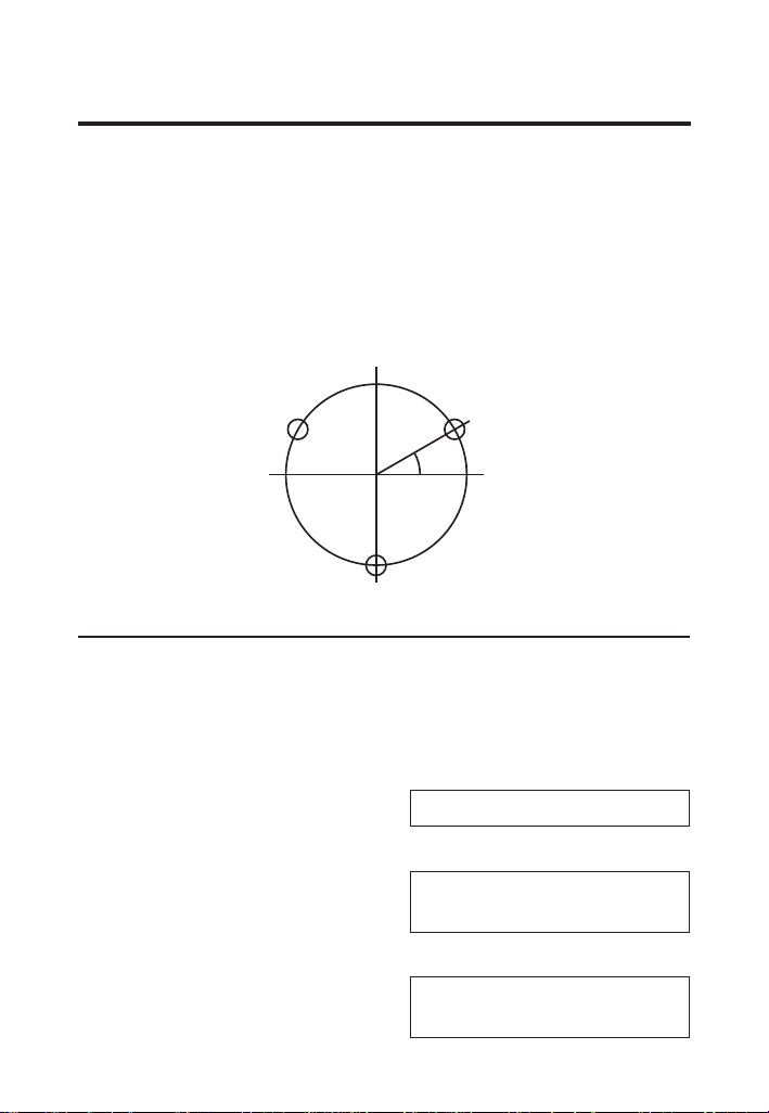
BOLT PATTERN
With the Machinist Calc Pro 2, you can determine a Bolt
Pattern by entering the Bolt Circle Diameter, the Number of
Bolt Holes and the Angle of the first bolt hole (optional). You
can also enter an optional center x and y-coordinate of the
Bolt Pattern.
In addition to calculating the x and y-coordinates for each bolt
hole, the Bolt Pattern function also calculates the hole center-
to-center spacing (i.e. On-center distance from hole to hole).
Start
Angle
X
C
,Y
C
X
2
,Y
2
X
1
,Y
1
X
3
,Y
3
Bolt Pattern
Calculate the Bolt Pattern for a layout with a 3.5" Diameter,
a 20° Start Angle and 3 Bolts. The center x-coordinate is 10"
and the center y-coordinate is 15".
When determining angles, 0° is at the 3 o'clock position and
the rotation goes counterclockwise.
OO 0.
1. Enter the center x-coordinate:
10ia
ADJACENT
(x) 10. INCH
2. Enter the center y-coordinate:
15io
OPPOSITE
(y) 15. INCH
3844-UG4088E-E.indd 543844-UG4088E-E.indd 54 11/18/2022 6:50:14 AM11/18/2022 6:50:14 AM

User's Guide — 55
3. Enter the Start Angle:
20n
ANGLE
(Ө) 20.°
4. Enter Bolt Circle Diameter:
3.5d
DIAMETER
3.5 INCH
5. Enter the Number of Bolts:
3gd (Bolt Pattern)
NUMBER OF BOLTS
3.
6. Calculate center-to-center Spacing and the x and y
coordinates:
d
OC SPACING
3.031 INCH
d
BOLT POSITION
X-Ø1 11.644 INCH
d
BOLT POSITION
Y-Ø1 15.599 INCH
d
BOLT POSITION
X-Ø2 8.659 INCH
d
BOLT POSITION
Y-Ø2 16.125 INCH
d
BOLT POSITION
X-Ø3 9.696 INCH
d
BOLT POSITION
Y-Ø3 13.277 INCH
d
BOLT CIRCLE DIA
3.500 INCH
d
BOLT PATTERN CTR
X-ØØ 10.000 INCH
(cont'd)
3844-UG4088E-E.indd 553844-UG4088E-E.indd 55 11/18/2022 6:50:14 AM11/18/2022 6:50:14 AM
56 —
®
d
BOLT PATTERN CTR
Y-ØØ 15.000 INCH
d
STARTING ANGLE
20.000 °
RIGHT TRIANGLE FUNCTIONS
With the Machinist Calc Pro 2, you can easily solve Right
Triangle problems by simply entering two of four variables:
Adjacent, Opposite, Hypotenuse or Angle.
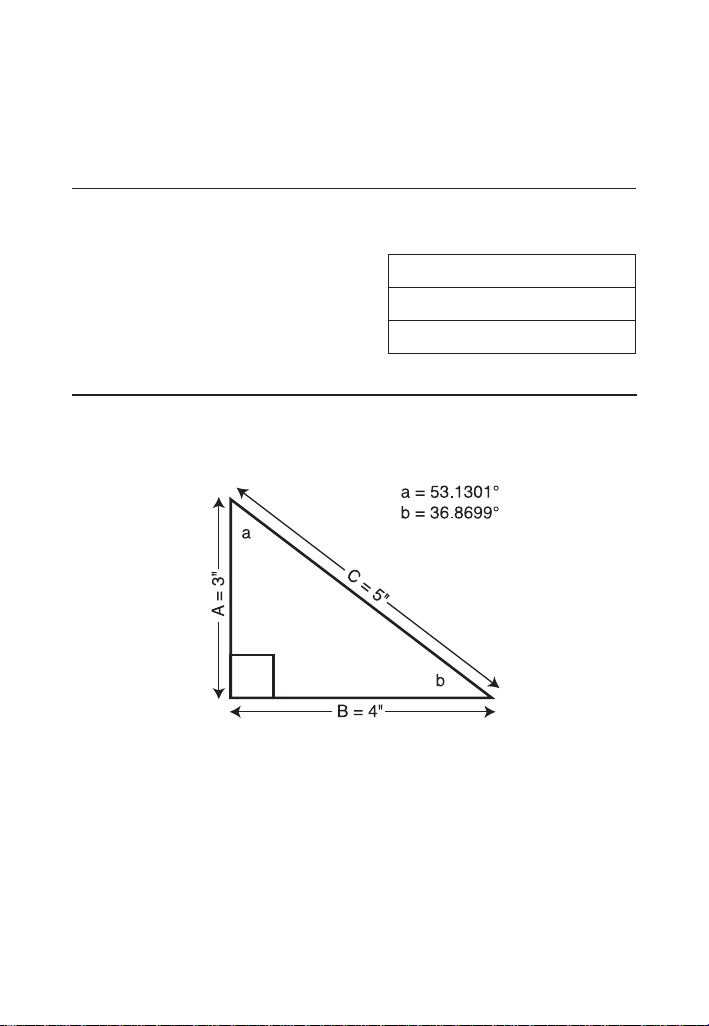
Right Triangle –
Calculate the Hypotenuse, Angle and Adjacent Angle of a right
triangle with an Adjacent Leg of 3 Inches and an Opposite Leg
of 4 Inches:
Opposite
Leg: 4
Hypotenuse
A
B
Adjacent
Leg: 3
OO
0.
1. Enter the Adjacent Leg Length:
3ia
ADJACENT
(x) 3. INCH
2. Enter the Opposite Leg Length:
4io
OPPOSITE
(y) 4. INCH
(cont'd)
3844-UG4088E-E.indd 563844-UG4088E-E.indd 56 11/18/2022 6:50:14 AM11/18/2022 6:50:14 AM

User's Guide — 57
3. Solve for the Hypotenuse:
h
HYPOTENUSE
(r) 5.000 INCH
4. Solve for the Angle (A):
n
ANGLE
(Ө) 53.130°
5. Solve for the Adjacent Angle (B):
n
ADJACENT ANGLE
36.870°
Right Triangle –
Calculate the Adjacent Angle, Adjacent Leg and Opposite Leg
of a right triangle with a Hypotenuse of 12 Inches and a known
Angle of 35.34°:
OO
0.
1. Enter the Hypotenuse:
12ih
HYPOTENUSE
(r) 12.
INCH
2. Enter the known Angle:
35.34n
ANGLE
(Ө) 35.34°
3. Solve for the Adjacent Angle:
n
ADJACENT ANGLE
54.660°
4. Solve for the Adjacent Leg:
(cont'd)
3844-UG4088E-E.indd 573844-UG4088E-E.indd 57 11/18/2022 6:50:14 AM11/18/2022 6:50:14 AM

58 —
®
a
ADJACENT
(x) 9.789
INCH
5. Solve for the Opposite Leg:
o
OPPOSITE
(y) 6.941
INCH
CIRCLE CALCULATIONS
Circumference and Area –
Find the Area and Circumference of a circle with a Diameter of
11 Inches:
OO
0.
11id
DIAMETER
11. INCH
d
CIRCULAR AREA
95.033 SQ INCH
d
CIRCUMFERENCE
34.558 INCH
BASIC D:M:S AND TRIGONOMETRY EX AMPLES
Converting Degrees:Minutes:Seconds
Convert 23°42'39" to decimal degrees:
OO
0.
23.42.39
DMS 23.42.39
g. (dms◄►deg)
23.710833°
Convert 44.29° to degrees:minutes:seconds format:
OO
0.
44.29g. (dms◄►deg)
DMS 44.17.24°
(cont'd)
3844-UG4088E-E.indd 583844-UG4088E-E.indd 58 11/18/2022 6:50:14 AM11/18/2022 6:50:14 AM
User's Guide —
Improperly formatted entries will be redisplayed in the correct
convention after any operator key is pressed. For example, 30° 89'
entered will be corrected and displayed as 31° 29' 0" or 31.483333°.
Time Calculations Using D:M:S
Add 7 Hours 45 Minutes 33 Seconds to 11 Hours 16 Minutes
20 Seconds:
OO
0.
7.45.33+
DMS 7.45.33°
11.16.20=
DMS 19.01.53°
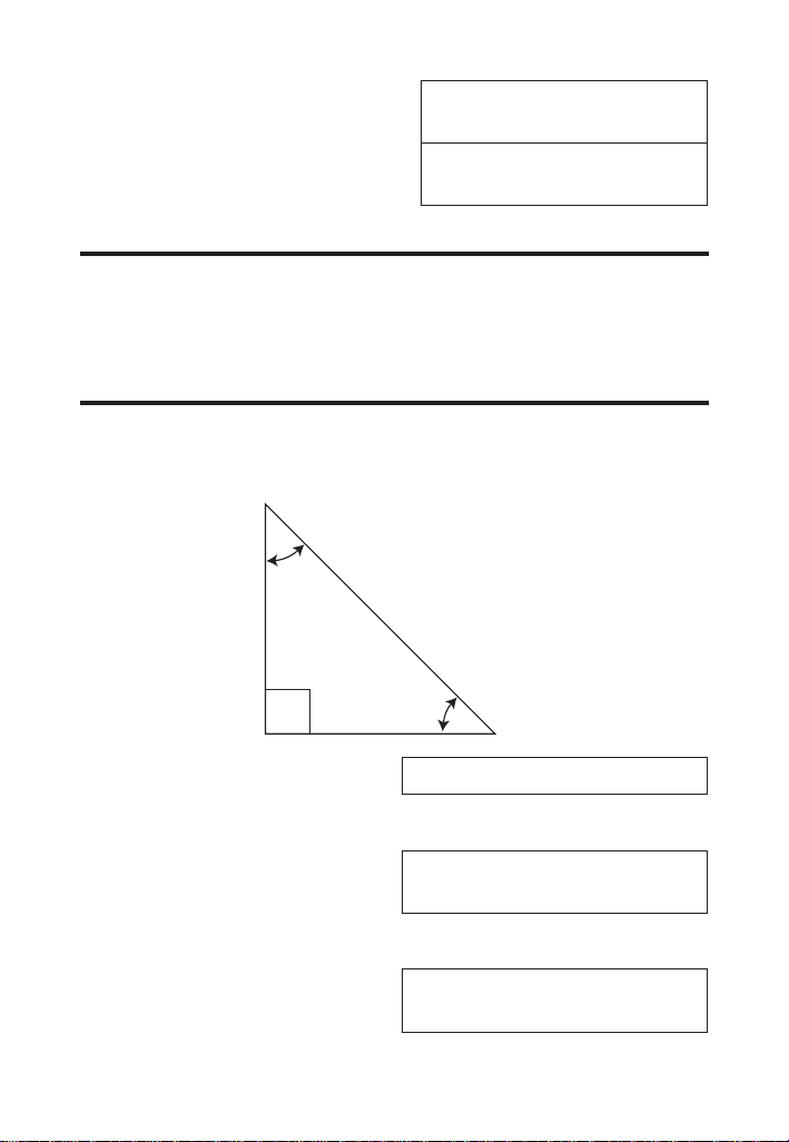
Trigonometric Functions
The following drawing and formulas list basic trigonometric
formulas, for your reference:
Given Side A and angle a, nd:
Side C
A , a go (Cos) =
(e.g., 3i,53.13go (Cos) =)
Side B
A * a gh (Tan) =
Angle b
90° - a =
Given Side A and angle b, nd:
(cont'd)
3844-UG4088E-E.indd 593844-UG4088E-E.indd 59 11/18/2022 6:50:14 AM11/18/2022 6:50:14 AM

—
®
Side B
A , b gh (Tan) =
Side C
A , b ga (Sine) =
Angle a
90° - b =
Given Side B and angle a, nd:
Side A
B , a gh (Tan) =
Side C
B , a ga (Sine) =
Given Side C and angle a, nd:
Side A
C * a go (Cos) =
Side B
C * a ga (Sine) =
Given Side A and Side C, nd:
Angle a
A , C =gi (ArcCos)
Angle b
A , C = gm (ArcSine)
Given Side B and Angle b, nd:
Side C
B , b go (Cos) =
Side A
B * b gh (Tan) =
(cont'd)
3844-UG4088E-E.indd 603844-UG4088E-E.indd 60 11/18/2022 6:50:14 AM11/18/2022 6:50:14 AM

User's Guide —
(cont'd)
APPENDIX A - WORKPIECE MATERIAL CONVERSION TABLE
WORKPIECE MATERIALS CONVERSION TABLE (1 of 3)
Material Hardness
AISI/ASTM/
SAE
DIN
WR
(DIN)
JIS BS SS
Low-carbon
Steel
120-170 HB 1020 C22 1.0402
S 20 C;
S 20 CK
S 22 C
055 M 15 1450
Medium-carbon
Steel
160-210 HB 1045 C45 Ck 45
1.0503
1.1191
S 45 C
S 48 C
080 M 46
1672;
1650
High-carbon
Steel
180-230 HB 1060 C60 Ck 60
1.0601
1.1221
S 58 C 060 A 62
1665
1678
Chromium-
molybdenum
Alloy Steel
175-225 HB 4140
41CrMo4
42CrMo4
1.7223
1.7225
SCM 4
SCM 440
SCM 440 (H)
SNB 7
708 M 40 2244
Nickel-
chromium-
molybdenum
Alloy Steel
175-225 HB 4340
40NiCrMo8-4
34CrNiMo6
36CrNiMo4
40NiCrMo6
1.6562
1.6582
1.6511
1.6565
SNB 24-1-5
SNCM 447
SNCM 439
816 M 40;
817 M 40
817 M 37
817 A 37;
818 M 40
2541
Chromium Alloy
Steel
175-225 HB 52100 100Cr6 1.3505 SUJ 2
2 S 135;
535 A 99
2258
3844-UG4088E-E.indd 613844-UG4088E-E.indd 61 11/18/2022 6:50:14 AM11/18/2022 6:50:14 AM

62 —
®
WORKPIECE MATERIALS CONVERSION TABLE (2 of 3)
Material Hardness
AISI/ASTM/
SAE
DIN
WR
(DIN)
JIS BS SS
Austenitic
Stainless Steel
150-200 HB 304
X5CrNi18-9
X2CrNi19-1;
GX2CrNiN18-9
X2CrNiN18-10
X5CrNi18-10
(X4CrNi18-10)
1.4306
1.4311
1.4301
SCS 19,
SUS 304 L
SUS 304LN
SUS 304
304 S 11; LW 20,
LWCF 20, S. 536,
T. 74, 304 C 12
(LT 196),
305 S 11, 304 S 61,
304 S 15;
304S16; 304 S 17;
LW21; LWCF 21;
304 S 31
2352
2371
2332
2333
Austenitic
Stainless Steel
150-200 HB 316
X5CrNiMo 17-12-2
(X4CrNiMo 17-12 2)
X3CrNiMo 17-13-3
(X5CrNiMo 17-13-3)
X6CrNiMoNb 17-12-2
1.4401
1.4436
1.4580
SUS 316
316S13,
17, 19,
31, 33
LW23; LWCF 23
318 S 17
2347
2343
Martensitic
Stainless Steel
150-200 HB 410
X6Cr13, X7Cr14
X12Cr13; X10Cr13;
GX12Cr13
1.4000;
1.4001
1.4006
SUS 403,
410 S, 429
SUS 410
403 S 17
410S21;
410 C 21; ANC 1A
2301
2302
Ferritic Stainless
Steel
135-185 HB 430 X6Cr17 1.4016 SUS 430
430S17;
430 S 18
2320
Mold type Tool
Steel
150-200 HB P20 1.2330
Hot work type
Tool Steel
200-250 HB H13 X40CrMoV51 1.2344 SKD61 BH13 2242
Copper Al Alloy 120 HB 2024-T3 AlCuMg2 3.1355
A2024,
A3x4
2L97,
2L98
(cont'd)
3844-UG4088E-E.indd 623844-UG4088E-E.indd 62 11/18/2022 6:50:14 AM11/18/2022 6:50:14 AM

User's Guide — 63
WORKPIECE MATERIALS CONVERSION TABLE (3 of 3)
Material Hardness
AISI/ASTM/
SAE
DIN
WR
(DIN)
JIS BS SS
Magnesium and
Silicon Al Alloy
95 HB 6061-T6 AlMgSiCu 3.3211
A6061,
A2x4
6061, H20, L117, L118
Silicon, Copper,
and Magnesium
Cast Al
125 HB A390.0-T5
Ti-6Al-4V Alloy 32-36 HRC Alpha-beta alloy TiAl6V4 TA 10-13; TA 28
Ti-10V-2Fe-3Al
Alloy
38-41 HRC Beta alloy
Nickel-base
Heat Resistant
alloys
36 HRC Alloy 718 NiCr19Fe19NbMo 2.4668 HR8
Nickel-base
Heat Resistant
alloys
89 HRB Alloy X NiCr22FeMo 2.4665 HR6,204
Cobalt-base
Heat Resistant
alloy
37 HRC Haynes alloy 188
3844-UG4088E-E.indd 633844-UG4088E-E.indd 63 11/18/2022 6:50:14 AM11/18/2022 6:50:14 AM

64 —
®
APPENDIX B – DEFAULT SETTINGS
After a Clear All (g*), your calculator will return to the
following settings:
STORED VALUES DEFAULT VALUE
Material None
Process Face Milling
Tool High Speed Steel Tool
Number Of Teeth 1
Drill Cut Angle 118°
Weight per Volume
490 Pounds Per
Cubic Foot
% Thread Grip 75%
Thread Classication
U.S. Threads Internal 2B
Metric Threads Internal 6H
If you replace your batteries or perform a Full Reset by depressing
the Reset button located above the d key, your calculator will
return to the following settings:
PREFERENCE SETTINGS DEFAULT VALUE
Default Unit Format Mode U.S. Mode
Fractional Resolution 1/64"
Functional Result Rounding 0.000
Area Answer Format Standard
Volume Answer Format Standard
Fractional Mode Standard
Mathematical Operation Order of Operations
3844-UG4088E-E.indd 643844-UG4088E-E.indd 64 11/18/2022 6:50:14 AM11/18/2022 6:50:14 AM

User's Guide — 65
APPENDIX C – PREFERENCE SETTINGS
The Machinist Calc Pro 2 has Preference Settings that allow
you to customize or set desired unit formats and calculations.
If you replace your batteries or perform a Full Reset by
depressing the Reset button located above the d key,
your calculator will return to the following settings (in addition
to those listed on the previous page), with the default setting
for each preference listed rst. If you want to reset your
calculator without changing the Default Unit Mode, you can
do a partial reset by turning the calculator o, holding down
* and pressing O.
PREFERENCE OPTIONS
1) Default Unit
Format Mode
– U.S. MODE: unitless values
stored within Machinist functions
are automatically assigned the
corresponding default U.S. units of the
selected function.
– METRIC MODE: unitless values
stored within Machinist functions
are automatically assigned the
corresponding default Metric units of
the selected function.
2) Fractional
Resolution
– 1/64: displays fractional values to the
nearest 64th of an Inch.
– 1/2: displays fractional values to the
nearest half Inch.
– 1/4: displays fractional values to the
nearest quarter of an Inch.
– 1/8: displays fractional values to the
nearest 8th of an Inch.
– 1/16: displays fractional values to the
nearest 16th of an Inch.
– 1/32: displays fractional values to the
nearest 32nd of an Inch.
(cont'd)
3844-UG4088E-E.indd 653844-UG4088E-E.indd 65 11/18/2022 6:50:14 AM11/18/2022 6:50:14 AM

66 —
®
3) Functional
Result
Rounding
– 0.000 (FIX): calculation results using
Machinist functions are always
displayed to three decimal places.
– 0.0000 (FIX): calculation results
using Machinist functions are always
displayed to four decimal places.
– 0. (ACTUAL): calculation results
using Machinist functions are always
displayed to the maximum number of
decimal places.
4) Area Answer
Format
– STANDARD: if units entered are
the same – e.g., Inch x Inch – area
answers will remain in this format
(Square Inch), but if units entered are
dierent – e.g., Inches x Feet – area
answers will be displayed in Square
Feet.
– SQUARE FEET: area answers always
displayed in Square Feet, regardless
of unit entry – e.g., Inches x Inches =
Square Feet.
– SQUARE INCHES: area answers
always displayed in Square Inches,
regardless of unit entry – e.g., Feet x
Feet = Square Inches.
– SQUARE METERS: area answers
always displayed in Square Meters,
regardless of unit entry – e.g., Feet x
Feet = Square Meters.
(cont'd)
3844-UG4088E-E.indd 663844-UG4088E-E.indd 66 11/18/2022 6:50:14 AM11/18/2022 6:50:14 AM

User's Guide — 67
5) Volume
Answer
Format
– STANDARD: if units entered are the
same – e.g., Inch x Inch x Inch – the
answer will remain in this format (Cubic
Inch), but if units entered are dierent
– e.g., Feet x Feet x Inches – volume
answer will be displayed in Cubic Inch.
– CUBIC FEET: volume answers always
displayed in Cubic Feet, regardless
of unit entry – e.g., Inches x Inches x
Inches = Cubic Feet.
– CUBIC METERS: volume answers
always displayed in Cubic Meters,
regardless of unit entry – e.g., Feet x
Feet x Feet = Cubic Meters.
– CUBIC INCHES: volume answers
always displayed in Cubic Inches,
regardless of unit entry – e.g., Feet x
Feet x Feet = Cubic Inches.
6) Fractional
Mode
– STANDARD: fractions are displayed to
the nearest Fractional Resolution.
– CONSTANT: fractions are displayed in
the set Fractional Resolution.
7) Mathematical
Operation
– ORDER OF OPERATIONS: the
calculator uses the Order of Operations
Method (10 + 4 x 5 = 30).
– ORDER OF ENTRY: the calculator
uses the Order of Entry Method (as
entered: 10 + 4 x 5 = 70).
3844-UG4088E-E.indd 673844-UG4088E-E.indd 67 11/18/2022 6:50:14 AM11/18/2022 6:50:14 AM

68 —
®
HOW TO SET PREFERENCES
Press
g
, then
=
to access the Preferences menu.
Continue pressing
=
to toggle through dierent Preferences.
Press
+
or
-
keys to toggle between options of the
dierent Preferences. Press
O
to exit Preferences. Your
calculator will keep your Preference Settings until a Full Reset
alters your settings to the default values.
Accessing Preference Setting
To Set “Metric Mode”:
g= (Prefs) (rst press of =)
U.S. MODE
+ (plus sign)
METRIC MODE
+
U.S. MODE
To Set “Fractional Resolution”:
= (second press
of =)
FRAC. RESOLUTION 0-1/64 INCH
+ (plus sign)
FRAC. RESOLUTION 0-1/2 INCH
+
FRAC. RESOLUTION 0-1/4 INCH
+
FRAC. RESOLUTION 0-1/8 INCH
+
FRAC. RESOLUTION 0-1/16 INCH
+
FRAC. RESOLUTION 0-1/32 INCH
To Set “Functional Rounding":
= (third press
of =)
FUNCTIONAL ROUND FIX 0.000
+ (plus sign)
FUNCTIONAL ROUND FIX 0.0000
+
FUNCTIONAL ROUND ACT. 0.
3844-UG4088E-E.indd 683844-UG4088E-E.indd 68 11/18/2022 6:50:14 AM11/18/2022 6:50:14 AM

User's Guide —
To Set “Area” Answer Format:
= (fourth press of =)
AREA UNITS STD.
+ (plus sign)
AREA UNITS 0. SQ FEET
+
AREA UNITS 0. SQ INCH
+
AREA UNITS 0. SQ M
To Set “Volume” Answer Format:
= (fth press of =)
VOLUME UNITS STD.
+ (plus sign)
VOLUME UNITS 0. CU FEET
+
VOLUME UNITS 0. CU M
+
VOLUME UNITS 0. CU INCH
To Set "Fractional Mode":
= (sixth press
of =)
FRACTIONAL MODE STD. 0-1/2 INCH
+ (plus sign)
FRACTIONAL MODE FIX 0-32/64
To Set "Mathematical Operations" Method:
= (seventh press of =)
ORDER OF OPER MATH
+ (plus sign)
ORDER OF ENTRY MATH
Press O at any time to exit the Preference Mode. To Reset
your calculator to the default Preference Settings, turn o your calculator,
hold down the multiplication * key, and turn on. “ALL RESET” will ash
for one second before clearing the display.
3844-UG4088E-E.indd 693844-UG4088E-E.indd 69 11/18/2022 6:50:14 AM11/18/2022 6:50:14 AM

—
®
APPENDIX D – BASIC CALCULATOR
FUNCTIONS AND DIMENSIONAL
MATH OPERATIONS
ENTERING DIMENSIONS
Unlike other Calculated Industries/Construction Master
calculators, the Machinist Calc Pro 2 does not have a dedicated Feet
key. Feet is a secondary function located above the 7 key, so you
have to use the g key, then 7 to enter or calculate dimensions
using Feet. Below are some examples.
Enter 2 Feet, then label as square and cubic units:
2 Feet
2g7
2 FEET
2 square Feet
g7
2 SQ FEET
2 cubic Feet
g7
2 CU FEET
Enter 2 Feet, 3 Inches:
2g73i
2 FEET 3 INCH
Linear Dimensions
Examples of how linear dimensions are entered
(press O after each entry):
23 mils
23B
4.5 Inches
4.5i
95 millimeters
95m
1,320 Feet
1320g7
201 meters
201g9
3844-UG4088E-E.indd 703844-UG4088E-E.indd 70 11/18/2022 6:50:15 AM11/18/2022 6:50:15 AM

User's Guide —
Square and Cubic Dimensions
Examples of how square and cubic dimensions are entered
(press O after each entry):
14 square Inches
14ii
11 square millimeters
11mm
1.5 cubic meters
1.5g999
3 cubic Feet
3g7g7g7
CONVERSIONS
Linear Conversions
Convert 10 Feet 6 Inches to other dimensions,
including metric:
OO
0.
10g76i
10 FEET 6 INCH
gB*
126.000 INCH
g7 (Feet)
10.5 FEET
gi
126. INCH
gm
3200.4 MM
g5 (cm)
320.04 CM
g9 (m)
3.2004 M
* Converting a linear value using the B key will result in the decimal
Inch equivalent of the value, rounded to three decimal places. Only
unitless values are multiplied by 0.001 Inches when using this key.
Convert 15 Feet 9-1/2 Inches to decimal Feet. Then convert
back to Feet-Inch-Fractions.
3844-UG4088E-E.indd 713844-UG4088E-E.indd 71 11/18/2022 6:50:15 AM11/18/2022 6:50:15 AM

72 —
®
OO
0.
15g79i1/2
15 FEET 9-1/2 INCH
g7 (Feet)
15.791667 FEET
g7
15 FEET 9-1/2 INCH
Convert 17.32 Feet to Feet-Inch-Fractions:
OO
0.
17.32g7 (Feet)
17.32 FEET
=g7
17 FEET 3-27/32 INCH
g7
17.32 FEET
gi
207.84 INCH
g7g7
17 FEET 3-27/32 INCH
Convert 8-1/8 Inches to decimal Inches. Then convert to
decimal Feet:
OO
0.
8i1/8
8-1/8 INCH
gi
8.125 INCH
g7 (Feet)
0.6770833 FEET
Convert 9.0625 Inches to decimal Feet.
OO
0.
9.0625i
9.0625 INCH
g7 (Feet)
0.7552083 FEET
3844-UG4088E-E.indd 723844-UG4088E-E.indd 72 11/18/2022 6:50:15 AM11/18/2022 6:50:15 AM

User's Guide — 73
Square and Cubic Conversions
Convert 6 square Feet to other square dimensions:
OO
0.
6g7g7 (Feet)
6 SQ FEET
gm
557418.24 SQ MM
g9 (m)
0.5574182 SQ M
g5(cm)
5574.1824 SQ CM
Convert 0.05 cubic meters to other dimensions:
OO
0.
.05g999
(m)
0.05 CU M
gm
50000000. CU MM
g5 (cm)
50000. CU CM
gi
3051.1872 CU INCH
g7 (Feet)
1.7657333 CU FEET
Weight Conversions
Convert 1.5 tons to pounds and kilograms:
OO
0.
1.5g6 (tons)
1.5 TON
g1 (kg)
1360.7771 KG
g4 (lbs)
3000. LBS
Weight per Volume and Volume Conversions
Convert 2 cubic Feet of stainless steel to pounds, tons,
kilograms, and metric tons if the steel weighs 7,480 kilograms
per cubic meter:
OO
0.
3844-UG4088E-E.indd 733844-UG4088E-E.indd 73 11/18/2022 6:50:15 AM11/18/2022 6:50:15 AM

74 —
®
1. Store the weight per volume:
7480g0000*
(wt/vol)
KG/CU. METER
7480.
2. Enter steel volume:
2g7g7g7
2 CU FEET
3. Convert to pounds, tons, kilograms and metric tons:
g4 (lbs)
LBS.
933.92229
g6 (tons)
TON 0.4669611
g1 (kg)
KG 423.62003
g3 (met tons)
MTON 0.42362
4. Change the weight per volume back to the default value:
490g00 (wt/vol)
LBS./ CU. FEET
490.
* The number of 0 presses may vary, depending on the last units
displayed when wt/vol was last recalled/stored. By default, pounds
per cubic foot is displayed rst.
Calculating Percentages
The % key can be used for nding a given percent of a
number or for working add-on, discount or division percentage
calculations. It can be used with any type of number, in
any dimension (Feet, Inch, millimeter, etc.) and any type of
convention (non-dimensioned, linear, square or cubic). Find
18% of 50 Feet:
OO
0.
50g7*18%
9. FEET
Take 20% from 17 Feet 6 Inches:
17g76i-20%
14 FEET 0 INCH
3844-UG4088E-E.indd 743844-UG4088E-E.indd 74 11/18/2022 6:50:15 AM11/18/2022 6:50:15 AM

User's Guide — 75
BASIC MATH OPERATIONS
Adding and Subtracting Dimensions
Add the following measurements:
• 6 Feet 2-1/2 Inches
• 11 Feet 5-1/4 Inches
• 18.25 Inches
Then subtract 2-1/8 Inches:
6g72i1/2+
6 FEET 2-1/2 INCH
11g75i1/4+
17 FEET 7-3/4 INCH
18.25i=
19 FEET 2 INCH
-2i1/8=
18 FEET 11-7/8 INCH
Multiplying Dimensions
Multiply 5 Feet 3 Inches by 11 Feet 6-1/2 Inches:
5g73i*
5 FEET 3 INCH
11g76i1/2=
60.59375 SQ FEET
Multiply 2 Feet 7 Inches by 10:
2g77i*10=
25 FEET 10 INCH
Dividing Dimensions
Divide 30 Feet 4 Inches by 7 Inches:
30g74i,7i=
52.
Divide 20 Feet 3 Inches by 9:
20g73i,9=
2 FEET 3 INCH
3844-UG4088E-E.indd 753844-UG4088E-E.indd 75 11/18/2022 6:50:15 AM11/18/2022 6:50:15 AM

76 —
®
APPENDIX E – ACCURACY/ERRORS, AUTO
SHUT-OFF, BATTERIES, RESET
ERROR CODES
DISPLAY ERROR TYPE
OVERFLOW Overow (too large)
MATH ERROR Divide by 0
DIMENSION ERROR Dimension error
ENTRY ERROR Invalid entry error
AUTO SHUT
-
OFF
Your calculator is designed to shut o after about 4 minutes of
non-use.
BATTERY
The Machinist Calc Pro 2 uses one CR2025 (included). This
should last approximately 800 hours of actual use. Should your
calculator display become very dim or erratic, replace the battery.
Please use caution when disposing of your
old battery, as it contains hazardous chemicals.
Replacement batteries are available at most
discount or electronics stores. You may also call
Calculated Industries at 1-775-885-4900.
Battery Replacement Instructions
While the calculator is o, turn the calculator over and use a
#1 Phillips screwdriver to remove the battery holder screw
located near the center at the top. With the screw removed,
pull battery holder out, remove old battery, and slide new
battery into holder. The negative side of the battery should be
facing you as you insert the battery holder into the calculator.
Replace screw using a #1 Phillips screwdriver.
3844-UG4088E-E.indd 763844-UG4088E-E.indd 76 11/18/2022 6:50:15 AM11/18/2022 6:50:15 AM

User's Guide — 77
RESET
If your calculator should ever "lock up," insert the tip of a
paperclip or a small diameter wire into the small Reset hole
above the d key.
REPAIR AND RETURN
RETURN GUIDELINES
1. Please read the Warranty in this User's Guide to
determine if your Calculated Industries product remains
under warranty before calling or returning any device for
evaluation or repairs.
2. If your product won't turn on, check the battery as outlined
in the User's Guide.
3. If you need more assistance, please go to the website
listed below.
4. If you believe you need to return your product, please call a
Calculated Industries representative from 7 a.m. to
4 p.m. Pacic Time for additional information and a Return
Authorization (RA).
Call Toll Free: 1-800-854-8075
Outside USA: 775-885-4900
www.calculated.com/warranty
WARRANTY
Calculated Industries ("CI") warrants this product against
defects in materials and workmanship for a period of one (1)
year from the date of original consumer purchase in the U.S.
If a defect exists during the warranty period, CI at its option
will either repair (using new or remanufactured parts) or
replace (with a new or remanufactured calculator) the product
at no charge.
3844-UG4088E-E.indd 773844-UG4088E-E.indd 77 11/18/2022 6:50:15 AM11/18/2022 6:50:15 AM

78 —
®
THE WARRANTY WILL NOT APPLY TO THE PRODUCT
IF IT HAS BEEN DAMAGED BY MISUSE, ALTERATION,
ACCIDENT, IMPROPER HANDLING OR OPERATION,
OR IF UNAUTHORIZED REPAIRS ARE ATTEMPTED OR
MADE. SOME EXAMPLES OF DAMAGES NOT COVERED
BY WARRANTY INCLUDE, BUT ARE NOT LIMITED TO,
BATTERY LEAKAGE, BENDING, A BLACK "INK SPOT" OR
VISIBLE CRACKING OF THE LCD, WHICH ARE PRESUMED
TO BE DAMAGES RESULTING FROM MISUSE OR ABUSE.
To obtain warranty service in the U.S., please go to the
website. A repaired or replacement product assumes the
remaining warranty of the original product or 90 days,
whichever is longer.
Non-Warranty Repair Service – U.S.A.
Non-warranty repair covers service beyond the warranty
period, or service requested due to damage resulting from
misuse or abuse. Contact Calculated Industries at the number
listed above to obtain current product repair information and
charges. Repairs are guaranteed for 90 days.
Repair Service – Outside the U.S.A.
To obtain warranty or non-warranty repair service for goods
purchased outside the U.S., contact the dealer through which
you initially purchased the product. If you cannot reasonably
have the product repaired in your area, you may contact CI
to obtain current product repair information and charges,
including freight and duties.
3844-UG4088E-E.indd 783844-UG4088E-E.indd 78 11/18/2022 6:50:15 AM11/18/2022 6:50:15 AM

User's Guide —
Disclaimer
CI MAKES NO WARRANTY OR REPRESENTATION,
EITHER EXPRESS OR IMPLIED, WITH RESPECT
TO THE PRODUCT'S QUALITY, PERFORMANCE,
MERCHANTABILITY, OR FITNESS FOR A PARTICULAR
PURPOSE. AS A RESULT, THIS PRODUCT, INCLUDING
BUT NOT LIMITED TO, KEYSTROKE PROCEDURES,
MATHEMATICAL ACCURACY AND PREPROGRAMMED
MATERIAL, IS SOLD "AS IS," AND YOU THE PURCHASER
ASSUME THE ENTIRE RISK AS TO ITS QUALITY AND
PERFORMANCE. IN NO EVENT WILL CI BE LIABLE
FOR DIRECT, INDIRECT, SPECIAL, INCIDENTAL, OR
CONSEQUENTIAL DAMAGES RESULTING FROM ANY
DEFECT IN THE PRODUCT OR ITS DOCUMENTATION.
The warranty, disclaimer, and remedies set forth above are
exclusive and replace all others, oral or written, expressed
or implied. No CI dealer, agent, or employee is authorized to
make any modication, extension, or addition to this warranty.
Some states do not allow the exclusion or limitation of implied
warranties or liability for incidental or consequential damages,
so the above limitation or exclusion may not apply to you. This
warranty gives you specic rights, and you may also have
other rights, which vary from state to state.
FCC Class B
This equipment has been certified to comply with the limits for
a Class B calculating device, pursuant to Subpart J of Part 15
of FCC rules.
3844-UG4088E-E.indd 793844-UG4088E-E.indd 79 11/18/2022 6:50:15 AM11/18/2022 6:50:15 AM

—
®
Legal Notes
Software copyrighted and licensed by Calculated Industries,
Inc., 2023. User's Guide copyrighted by Calculated Industries,
Inc., 2023. Machinist Calc
®
and Calculated Industries
®
are
registered trademarks of Calculated Industries, Inc. © 2023.
ALL RIGHTS RESERVED
Designed in the USA
LOOKING FOR NEW IDEAS
Calculated Industries, a leading manufacturer of special-
function calculators and measuring instruments, is always
looking for new product ideas in these areas.
If you have a new product idea, please visit our "Bright Idea"
page at www.calculated.com/brightidea.asp. For suggestions
about improving this product or other products, please visit us
at www.calculated.com under "Contact Us". Thank You.
3844-UG4088E-E.indd 803844-UG4088E-E.indd 80 11/18/2022 6:50:15 AM11/18/2022 6:50:15 AM

User's Guide —
3844-UG4088E-E.indd 813844-UG4088E-E.indd 81 11/18/2022 6:50:15 AM11/18/2022 6:50:15 AM

4840 Hytech Drive
Carson City, NV 89706 USA
1-800-854-8075 • Fax: 1-775-885-4949
E-mail: [email protected]
calculated.com
Designed in the United States of America.
Printed in China.
01/23
UG4088E-E
3844-UG4088E-E.indd 823844-UG4088E-E.indd 82 11/18/2022 6:50:15 AM11/18/2022 6:50:15 AM
