
C
M
Y
CM
MY
CY
CMY
K
PRG4090E-C_COVER.ai 1 11/20/2020 3:05:21 PMPRG4090E-C_COVER.ai 1 11/20/2020 3:05:21 PM

USER’S GUIDE — 1
The custom-designed Sheet Metal/HVAC Pro Calc calculator was
specifically created for sheet
metal pro’s to ease the task of
performing mathematics on the job. It includes the most popular
built-in formulas for sheet metal computations, so you’ll save time,
increase accuracy and eliminate errors.
Your Calculator Helps You Solve:
• Dimensional Math Problems
• Conversions Between Feet-Inch-Fractions, Decimal Feet,
Decimal Inches and Metric
• Problems Involving All Common Fractions – 1/2” to 1/64”
• Area/Volume Calculations
• Arc/Circle/Column/Cone Areas and Volumes
• D:M:S
• Scientific Notation, Cubed Root
• Offset Calculations
• Trigonometry
• Law of Cosines
• Fan Laws 1, 2 and 3
• Velocity/Velocity Pressure Conversions
• Right Angle/Rafter Solutions
• Stair Layout (Risers/Treads), and more!
It also includes handy construction math and material estimation
examples — such as right angle/rafter and stair calculations — that
will also help you build faster and more accurately.
INTRODUCTION

2 —
SHEET METAL
/HVAC PRO CALC
KEY DEFINITIONS ............................................................................6
BASIC OPERATION KEYS.............................................................6
CONVERT Ç KEY—UNIT CONVERSIONS and
SECOND FUNCTIONS................................................................6
MEMORY and STORAGE FUNCTIONS ........................................7
RECALL ® KEY ..........................................................................8
FEET-INCH-FRACTION and METRIC KEYS .................................8
TRIGONOMETRIC KEYS ...............................................................9
PYTHAGOREAN THEOREM/RIGHT TRIANGLE KEYS..............10
LAW OF COSINES/NON-90 DEGREE TRIANGLE KEYS ...........12
OFFSET KEYS..............................................................................13
FAN LAW KEYS ............................................................................14
VELOCITY PRESSURE/FPM KEYS ............................................15
CIRCULAR/ARC FUNCTION KEYS .............................................15
COLUMN/CONE KEY ...................................................................16
HIP/VALLEY and JACK RAFTER KEYS.......................................17
STAIR KEY....................................................................................19
GETTING STARTED........................................................................21
ORDER OF OPERATIONS...........................................................21
USING PARENTHESES ...............................................................22
SETTING FRACTIONAL RESOLUTION.......................................23
Setting Fraction Resolution to Other Than 16ths —
Using the Preference Setting Mode .......................................23
Setting Fixed/Constant Fractional Resolution............................24
ENTERING DIMENSIONS............................................................25
Entering Linear Dimensions.......................................................25
Entering Square/Cubic Dimensions...........................................25
CONVERSIONS (LINEAR, AREA, VOLUME) ..............................27
Linear Conversions ....................................................................27
Converting Feet-Inch-Fractions to Decimal Feet .......................27
Converting Decimal Feet to Feet-Inch-Fractions .......................27
Converting Fractional Inches to Decimal Inches .......................27
Converting Decimal Inches to Fractional Inches .......................28
Square Conversions ..................................................................28
Cubic Conversions.....................................................................28
PERFORMING BASIC MATH WITH DIMENSIONS....................29
Adding Dimensions ....................................................................29
Subtracting Dimensions .............................................................29
Multiplying Dimensions ..............................................................29
TABLE OF CONTENTS

USER’S GUIDE — 3
Dividing Dimensions ..................................................................29
Percentage Calculations ............................................................30
MEMORY OPERATION ................................................................31
EXAMPLES — USING THE SHEET METAL/HVAC PRO ..............33
BASIC EXAMPLES .......................................................................34
Adding Linear Measurements ....................................................34
Converting Feet-Inch-Fractions to Decimal Feet and
Fractions of an Inch ................................................................34
Converting Feet-Inches to Meters and Millimeters ....................34
Adding and Subtracting Fractions of an Inch.............................35
Converting Fractions to Decimals..............................................35
Converting Decimals to Fractions..............................................35
Finding Length (of Iron) Required..............................................35
Circumference of a Circle ..........................................................36
Circumference and Area of a Circle...........................................36
Square Area (x
2
).........................................................................36
Area of a Rectangle ...................................................................36
Area of a Triangle ......................................................................37
Volume of a Rectangular Box ....................................................37
Volume of a Rectangular Container, Converting to
Cubic Meters...........................................................................37
Volume of a Cylinder..................................................................38
Volume of a Cone ......................................................................38
Cubed Function..........................................................................39
Cubed Root Function.................................................................39
Scientific Notation ......................................................................39
TRIGONOMETRIC FUNCTIONS..................................................40
Finding Sine, Cosine, Tangent...................................................41
Finding “Angle A” (ArcSin, ArcCos, ArcTan) ..............................41
Using Trigonometry to Find Unknown Side ...............................41
Using Trigonometry to Find Unknown Angle or Side.................42
Converting Pitch to Angle/Tangent.............................................45
D:M:S EXAMPLE ..........................................................................45
Converting Degrees:Minutes:Seconds ......................................45
VELOCITY PRESSURE/VELOCITY EXAMPLES.........................46
Converting Velocity Pressure to FPM ........................................46
Converting FPM to Velocity Pressure ........................................47
OFFSET EXAMPLES....................................................................48
Offset, Basic Example................................................................48
OGEE Offset in Feet-Inch-Fractions..........................................49
OGEE Offset, in Millimeters.......................................................50

4 — SHEET METAL/HVAC
PRO CALC
Dividing Offset into Multiple Degreed Elbows for
Manageable Sections .............................................................51
Change OGEE Offset ................................................................53
LAW OF COSINES EXAMPLES...................................................55
Field Measuring for Ductwork Using the Law of Cosines
Introduction .............................................................................55
Non-90 Degree Triangle Measurement Using Law of Cosines
and Heron’s Theorem .............................................................56
Using Law of Cosines and Pythagorean Theorem to
Calculate Offset, Length, and Angle .......................................58
Sheet Metal Panels for an Irregular Hip Roof............................59
Inline Duct, Single Offset (Computing Offset, Length,
and Angle)...............................................................................60
Inline Duct, Double Offset (Computing Offset, Length,
and Angle)...............................................................................62
Objects at Right Angles .............................................................65
Calculating Angles Between Objects (“Angle Between”)...........69
Calculating Angles Between Objects Example..........................70
FAN LAW EXAMPLES ..................................................................75
Fan Law 1 ..................................................................................75
Fan Law 2 ..................................................................................76
Fan Law 3 ..................................................................................77
ARC/CIRCLE EXAMPLES ............................................................78
Arc Length — Degree and Diameter Known .............................78
Arc Length — Degree and Radius Known.................................78
Using ArcK to Calculate an Arc Length......................................78
Arc Calculations — Arc Length and Diameter Known...............79
Arched/Circular Rake-Walls — Chord Length and Segment
Rise Known.............................................................................80
Arched Windows ........................................................................81
CONCRETE/PAVING ....................................................................82
Squaring-up a Foundation .........................................................82
Volume of a Rectangle...............................................................82
Volume of Columns....................................................................83
RIGHT TRIANGLE and ROOF FRAMING EXAMPLES ...............84
Roof Framing Definitions ...........................................................84
Degree of Pitch ..........................................................................86
Percent Grade............................................................................86
Common Rafter Length..............................................................87
Common Rafter Length — Pitch Unknown................................87
Angle and Diagonal (Hypotenuse).............................................88

USER’S GUIDE — 5
Rise ............................................................................................88
Rise and Diagonal......................................................................88
Sheathing Cut ............................................................................89
Regular Hip/Valley and Jack Rafters .........................................89
Jack Rafters — Using Other Than 16 Inch On-Center
Spacing...................................................................................91
Irregular Hip/Valley and Jack Rafters — Descending, with
On-Center Spacing Maintained ..............................................92
STAIR LAYOUT EXAMPLES ........................................................94
Stair Layout Definitions ..............................................................94
Stairs — Given Only Floor-to-Floor Rise ...................................96
Stairs — Given Only the Run.....................................................98
Stairs — Given Rise and Run....................................................99
Baluster Spacing ......................................................................100
APPENDIX A — TRIGONOMETRY FORMULAS .........................101
APPENDIX B — AREA/VOLUME FORMULAS............................102
AREA FORMULAS......................................................................102
SURFACE AREA/VOLUME FORMULAS ...................................103
APPENDIX C — OFFSET FORMULAS ........................................104
APPENDIX D — LAW OF COSINES/HERON’S THEOREM
FORMULAS ................................................................................105
APPENDIX E — FAN LAW FORMULAS ......................................106
APPENDIX F — DEFAULT SETTINGS.........................................106
APPENDIX G — PREFERENCE SETTINGS................................107
How to Set Preferences ..............................................................110
Accessing Preference Settings....................................................111
APPENDIX H — CARE INSTRUCTIONS......................................113
APPENDIX I — ACCURACY, AUTO SHUT-OFF, BATTERIES,
ERRORS .....................................................................................114
Accuracy/Errors ...........................................................................114
Auto Shut-Off...............................................................................115
Battery(ies) ..................................................................................115
Replacing the Battery(ies) ...........................................................115
Battery Replacement Instructions ...............................................115
Reset Key ....................................................................................115
REPAIR AND RETURN..................................................................116
WARRANTY ...................................................................................117
INDEX.............................................................................................119

6 — SHEET METAL/HVAC
PRO CALC
BASIC OPERATION KEYS
o
On/Clear — Turns power on. Pressing once clears the
display. Pressing twice clears all temporary values.
O
Turns all power off, clearing all non-permanent registers.
+ – x Arithmetic operation keys.
÷ =
Ç + Percent (%) — Four-function percent. See page 30
for examples.
0 – 9 and • Keys used for entering digits.
B Backspace Key — Used to delete entries one key-
stroke at a time (unlike the o function, which
deletes the entire entry).
CONVERT Ç KEY —
UNIT CONVERSIONS and SECOND FUNCTIONS
The Ç key is to convert between measurement units or to access
second functions, listed below:
Ç Convert — Used with the measurement keys to
convert between units or with other keys to access
special functions.
Ç x Clear All — Clears all values, including Memory.
Resets all permanent entries to default values
(except Preference Settings, which are retained).
Note: Use only when necessary, as it deletes all stored values.
X Squares the value in the display. For example, to
Square the value ten, enter 1 0 then press X.
Ç X x
3
— Cubes the value in the display. For example, to
Cube the value ten, enter 1 0 then press ÇX.
√ Square Root Function — Used to find the Square
Root of a non-dimensional or area value
(e.g., 1 0 0 √ = 10).
KEY DEFINITIONS

USER’S GUIDE — 7
Ç √
Ç /
Ç ÷
Ç
–
π
Ç π
Ç •
Ç =
Cube Root Function — Used to find
the Cube Root
of a non-dimensional or volume value
(e.g., 1000Ç√= 10).
x10
y
— Allows entry of an exponent. For example,
8Ç/14is 8 times 10 to the 14th power
(8x10
14
).
1/x — Finds the reciprocal of a number (e.g., 8
Ç÷= 0.125).
Change (+ / –) Sign — Changes the sign of the dis-
played value to negative or positive.
Pi — Constant = 3.141593
ArcK — Constant = 0.017453. This value is equiva-
lent to the constant of a 1° arc angle for a one-unit
value. The formula for this constant is π ÷ 180.
Degrees:Minutes:Seconds — Converts between
D:M:S and Decimal Degree formats.
Note: Your calculator uses a floating d:m:s format (that is, dis-
plays decimal degrees to the maximum number of decimal points,
for greater accuracy). If you desire rounding to two decimal points
(0.00°), you must set your calculator via Preference Settings (see
page 107).
Access Preference Settings — Used to access
various customizable settings, such as dimensional
answer formats (see Preference Settings on page
107).
MEMORY and STORAGE FUNCTIONS
Your calculator has two types of Memory:
1) basic Memory or Semi-Permanent, Cumulative µ;
2) non-cumulative Storage Registers (M1-M3).
µ Semi-Permanent Memory — Adds any displayed
number, dimensioned or unitless, to the semi-per-
manent, accumulating Memory. Values can be sub-
tracted from this Memory using Ç µ. ® ®
will recall and clear the Memory. Ç ® will swap
the value stored in accumulative Memory with the
value that is currently displayed.

8 — SHEET METAL/HVAC PRO CALC
Ç 1 Storage Register (M1) — Stores the displayed
value in non-cumulative, permanent Memory (e.g.,
1 0 Ç 1, ® 1 = 10). Good for storing a
single value, for future reference.
Note: Non-cumulative means it only accepts one value (does not
add or subtract) and a second entered value will replace the first.
Permanent means the value is stored even after the calculator is
shut off. To delete a stored value, enter a new value or perform a
Clear All (Çx).
Ç 2 Storage Register (M2) — Same function as Ç
1. See above.
Ç 3 Storage Register (M3) — Same function as Ç
1. See above.
RECALL ® KEY
The ® key is used to recall or review stored values (e.g., ® p
to recall a previously entered pitch value). It is also used in review-
ing stored settings and Memory operation (see below).
® ® Clear M+ — Displays and clears M+.
® µ Recall M+ — Displays value stored in M+.
® 1 Recall M1 — Recalls the stored value in M1.
® 2 Recall M2 — Recalls the stored value in M2.
® 3 Recall M3 — Recalls the stored value in M3.
FEET-INCH-FRACTION and METRIC KEYS
The following keys are used for entering units of measure, with ease
and accuracy:
f Enters or converts to Feet. Also used with the i
and / keys for entering Feet-Inch values (e.g., 6
f 9 i 1 / 2).
Note: Repeated presses after Ç toggle between Feet-Inches and
Decimal Feet (e.g., 6 f 9 i 1 / 2 Ç f = 6.791667
FEET; press f again to return to Feet-Inch-Fractions).
USER’S GUIDE — 9
i Enters or converts to Inches. Also used with the /
key for entering fractional inch values (e.g., 9 i
1 / 2).
Note: Repeated presses after Ç toggle between Fractional
and Decimal Inches (e.g., 9 i 1 / 2 Ç i = 9.5
INCH; press i again to return to Inch-Fractions).
/ Fraction Bar — Used to enter Fractions. Fractions
may be entered as proper (1/2, 1/8, 1/16) or improper
(3/2, 9/8). If the denominator (bottom) is not entered,
the calculator's fractional resolution setting is auto-
matically used (e.g., entering 1 5 / = or +
will display 15/16, based on the default fractional
resolution setting of 16ths.
m Meters — Enters or converts to Meters.
Ç m Millimeters — Enters or converts to Millimeters.
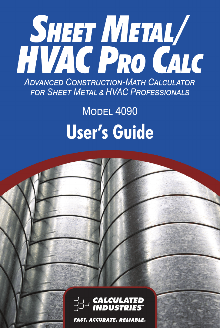
TRIGONOMETRIC KEYS
Tangent Ø = Opposite
Adjacent
Sine Ø = Opposite
Hypotenuse
Cosine Ø = Adjacent
Hypotenuse
10 — S
HEET METAL/HVAC PRO CALC
Your calculator has standard trigonometric keys, in addition to Right
Triangle keys (e.g., R, r, d and p), for advanced Right Triangle
mathematics.
The Sine, Cosine, and Tangent of an angle are defined in relation to
the sides of a Right Triangle.
Using the Ç key with the trigonometric function gives you the
Arcsine, Arccosine and Arctangent – all of which are used to find the
Angle for the Sine, Cosine, or Tangent value entered.
S Sine Function — Calculates the Sine of a Degree
or undimensioned* value.
Ç S Arcsine (sin
-1
) — Calculates the angle for the
entered or calculated Sine value.
ç Cosine Function — Calculates the Cosine of a
Degree or undimensioned* value.
Ç ç Arccosine (cos
-1
) — Calculates the angle for the
entered or calculated Cosine value.
t Tangent Function — Calculates the Tangent of a
Degree or undimensioned* value.
Ç t Arctangent (tan
-1
) — Calculates the angle for the
entered or calculated Tangent value.
*Note: Cannot use on dimensioned values.
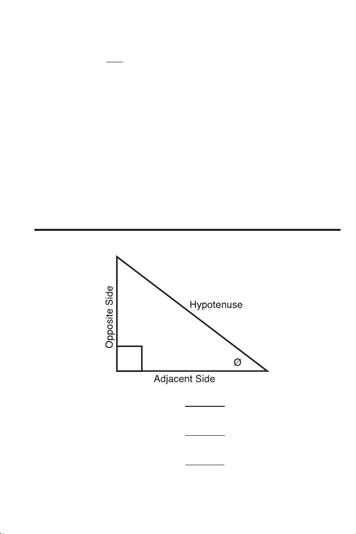
PYTHAGOREAN THEOREM / RIGHT TRIANGLE KEYS

USER’S GUIDE — 11
Using the Pythagorean Theorem, the top row of keys
on your Sheet
Metal/HVAC Pro Calc provides instant solutions in dimensional format
to Right Triangle problems for sheet metal problems and roof framing.
The Right Triangle is calculated simply by entering two of four variables:
1) x (Run)
2) y (Rise)
3) r (Diagonal, or Hypotenuse); or
4) θ (Theta/Pitch).
R Run — Enters or calculates “x,” or the Run or hori-
zontal leg (base) of a Right Triangle.
r Rise — Enters or calculates “y,” or the Rise or verti-
cal leg (height) of a Right Triangle.
d Hypotenuse or Diagonal (for Roof Framing) —
Enters or calculates the Hypotenuse or diagonal leg
of a Right Triangle. Typical applications in construc-
tion/framing are “Squaring-up” slabs or finding
Common rafter lengths. Additional presses of the d
key will also display Plumb and Level cut angles in
degrees.
Note: The Common rafter calculation is the “point-to-point” length
and does not include the overhang or ridge adjustment.
p Theta — Enters or calculates the Pitch (slope) of a
roof (or Right Triangle). Pitch is the amount of “Rise”
over 12 Inches of “Run.” Pitch may be entered as:
• a Dimension: 9 i p
• an Angle or Degrees: 3 0 p
• a Percentage (percent grade): 7 5 Ç + p
Once a Pitch in one of the above formats is entered,
consecutive presses of p will convert to the remain-
ing pitch formats listed above (e.g., Pitch in Inches
will convert to Pitch Degrees, Percent Grade and
Pitch Ratio/Slope).
Note: An entered (vs. calculated) Pitch is a permanent entry. This
means that it will remain stored even after you turn the calculator
off. To change the Pitch, simply enter a new Pitch value.
In contrast, a calculated Pitch value is not permanently stored.
This means that the calculator will return to the Pitch value you
last entered when you press o twice.

12 — S
HEET METAL/HVAC PRO CALC
LAW OF COSINES / NON-90 DEGREE TRIANGLE KEYS
Ç 9 Law of Cosines — These keys are used for non-90
degree triangle mathematics and are incorporated
with Right Triangle mathematics (using “Measured”
non-90 degree and “Calculated” Right Triangles),
particularly, for finding the dimensional relationship
of distance and alignment between two or more
objects. The overall purpose of these calculations is
to develop the duct and/or fittings required to fill a
space.
These keys calculate the opposite angles A, B, and
C given entry of Side a, b, and c using the Law of
Cosines (see Storage Registers a, b, and c below)
and triangle area using Heron’s Theorem. They also
enable the computation of Right Triangle lengths “x,”
“y,” “r ” and Theta, for determining Offset, Length,
and Angle.
Press Result
1 Angle A
2 Angle B
3 Angle C
4 Area (using formula for Heron’s Theorem)
5 Redisplays entered Side a
6 Redisplays entered Side b
7 Redisplays entered Side c
Ç 4 Storage Register “a” — Enters Side “a” of a
Measured Triangle (e.g., if Side “a” is five feet, enter
5 f Ç 4).
Ç 5 Storage Register “b” — Enters Side “b” of a
Measured Triangle.
Ç 6 Storage Register “c” — Enters Side “c” of a
Measured Triangle.

USER’S GUIDE — 13
Right Triangle Functions:
R Length of Unknown Side — Calculates Side “x” of
unknown Right Triangle.
r Length of Unknown Side — Enters Side “y” of
unknown Right Triangle.
d Hypotenuse — Enters “c” of Measured Triangle as
“r” of unknown Right Triangle, for final determination
of “x” and “y.”
p Theta — Finds unknown angle for determination of
“x” and “y.”
OFFSET KEYS
Ç ( Offset — Calculates offset measurements, including
the Centerline Radius, Wrapper Length/Stretch-out,
Heel Radius, Throat Radius and Theta, given entry
of “x” (actual length), “y” (offset), and “a” (“end a”)
into the keys below:
Press Result
1 Centerline Radius (CR)
2 Wrapper Length/Stretch-out (WL)
3 Heel Radius
4 Throat Radius
5 Theta (THET)
6 Redisplays entered “x” (Actual Length)
7 Redisplays entered “y” (Offset)
8 Redisplays entered “a” (Storage
Register “a” or End “a”)
R Actual Length — Enters the actual length “x” for
offset calculations.
r Offset Length — Enters the offset “y.”
Ç 4 Storage Register “a” — Enters length of “end a”
for offset calculations.

14 — S
HEET METAL/HVAC PRO CALC
FAN LAW KEYS
Your calculator also has built-in formulas and keys that calculate Fan
Laws 1, 2 and 3, for air flow calculations. Each of these formulas
requires the entry of three variables in order to solve the fourth.
Ç R Fan Law 1 — Calculates the missing variable (e.g.,
“a-new” or “b-new” for CFM new or RPM new) for
Fan Law 1, given the three known variables into the
applicable Storage Registers (see below). See
page 75 for examples.
Ç r Fan Law 2 — Calculates the missing variable (e.g.,
“a-new” or “b-new” for CFM new or SP new) for Fan
Law 2, given the three known variables into the
applicable Storage Registers (see below). See
page 76 for examples.
Ç d Fan Law 3 — Calculates the missing variable (e.g.,
“a-new” or “b-new” for CFM new or BHP new) for
Fan Law 3, given the three known variables into the
applicable Storage Registers (see below). See
page 77 for examples.
Storage Registers Used For Fan Laws:
Ç 4 Storage Register “a” — Enters “a-old” or current
“a” value.
Ç 7 Storage Register “a-new” — Enters “a-new” or
new “a” value.
Ç 5 Storage Register “b” — Enters “b-old” or current
“b” value.
Ç 8 Storage Register “b-new” — Enters “b-new” or
new “b” value.

USER’S GUIDE — 15
VELOCITY PRESSURE / FPM KEYS
Ç 0 VP
ß ©
FPM — Converts entry to Velocity (Feet per
Minute - FPM), Velocity Pressure, Metric Velocity
(MPS) and Metric Velocity Pressure (kPA).
Press Result
1 Calculates Velocity (FPM) – assumes
entry is Velocity Pressure
2 Calculates Velocity Pressure – assumes
entry is Velocity (FPM)
3 Calculates Metric Velocity (MPS) –
assumes entry is kPA
4 Calculates Metric Velocity Pressure
(kPA) – assumes entry is MPS
See page 46 for examples.
CIRCULAR / ARC FUNCTION KEYS
The Circle key helps you quickly solve Circular Area, Volume or Arc
problems.
C Circle — Displays and calculates the following val-
ues, given an entered Circle Diameter* or Radius:
• Diameter
• Circumference
• Circle Area
*To enter a Diameter (e.g., ten feet), press 1 0 f C. To
enter a radius, see below.
Ç p Segment Radius — Enters or calculates the Circle
Radius (e.g., 5 f Ç p). Used to calculate
Diameter, Circumference and Circle Area (see
above).
Ç C Arc Length or Degree of Arc — A multi-function
key that enters or calculates Arc Length or Degree
of Arc, and further solves for additional Circular/Arc
values, including Arched Rake-Walls (based on the
stored on-center), listed on next page.
(Cont’d)

16 — S
HEET METAL/HVAC PRO CALC
(Cont’d)
If a Circle Diameter is entered into the C key and
Arc Degree (or Arc Length) entered into the Arc
function (Ç C), further presses of C will dis-
play and calculate the following:
Press Result
1 Arc Length or Degree of Arc
2 Chord Length
3 Segment Area
4 Pie Slice Area
5 Segment Rise
6 Stored On-Center Spacing
7 Length of Arched Wall 1
8 Length of Arched Wall 2
9 Length of Arched Wall 3
(if applicable), etc.*
*Note: The calculator will calculate Arched Rake-Wall stud sizes
with consecutive presses of the C key until it reaches the last
stud.
R Run (Chord Length) — Used with r or Ç p to
find the Chord Length or the Radius of a Circular
Segment. If the Segment Rise and Radius have
been entered, this key will display the Chord Length
of the Circular Segment.
r Rise — Used with R or Ç p to find the Rise or
the Radius of a Circular Segment. If the Chord
Length and Radius have been entered, this key will
display the Segment Rise of the Circular Segment.
COLUMN / CONE KEY
The Column and Cone functions help you quickly estimate volume
and surface area of Columns or Cones.
Ç ) Column and Cone — The first and second press of
) following Ç calculate the total volume and
surface area of a Column using the values stored in
C and r; the third and fourth consecutive press-
es of ) calculate the total volume and surface area
of a Cone.
USER’S GUIDE — 17
HIP/VALLEY and JACK RAFTER KEYS
Your calculator uses the y (rise), x (run), r (diagonal), θ (pitch), and
o.c. spacing values to calculate Regular (45°) and Irregular (non-45°)
Hip/Valley and Jack rafter lengths (excluding wood thickness, etc.).
When calculating Regular and Irregular Jack rafter lengths, you will
see the letters “JK” (Common Pitch side) or “IJ” (Irregular Pitch side)
and the corresponding Jack number to the left of your calculator dis-
play. This will help you keep track of the descending sizes and which
side the corresponding rafter is based on.
H Hip/Valley Rafter — Finds the Regular (45°) or
Irregular (non-45°) Hip/Valley rafter length.
• Regular Hip/Valley Length: After Right
Triangle/Rafter values are entered or calculated
(e.g., Pitch, Rise, Run), pressing H will calculate
the length of the Regular Hip/Valley rafter.
• Irregular Hip/Valley Length: If an Irregular Pitch is
entered via Ç H (see next page), pressing
H will calculate the Irregular Hip/Valley rafter
length. (An Irregular or “non-standard” roof has two
different Pitches/Slopes.)
(Cont’d)

18 — S
HEET METAL/HVAC PRO CALC
(Cont’d)
• Subsequent presses of the H key will also dis-
play Plumb, Level, and Cheek cut angle values in
degrees.
Ç H Irregular Pitch — Enters the Irregular or Secondary
Pitch value used to calculate lengths of the Irregular
Hip/Valley and Jack rafters.
You may enter the Irregular Pitch as:
• a Dimension: 9 i Ç H
• an Angle: 3 0 Ç H
• a Percentage: 7 5 Ç + Ç H
Note: An entered Irregular Pitch can be recalled by pressing ®
Ç H.
j Jack Rafters — Finds the descending Jack rafter
sizes for Regular pitched roofs, based on the stored
on-center spacing and previously entered or calcu-
lated Right Triangle/Rafter values (e.g., Pitch, Rise,
Run).
• The default On-Center spacing is 16 Inches. A new
On-Center spacing may be entered and permanent-
ly stored by entering an Inch value prior to perform-
ing the Jack Rafters function (e.g., 1 2 i
j). The current On-Center spacing value can be
viewed by pressing ® j.
• Repeated presses of the j key will display all
the rafter sizes (on the regular pitch side) as well as
display the Plumb, Level, and Cheek cut angle val-
ues. Additional presses will display the rafter sizes
on the Irregular Pitch side (if an Irregular Pitch was
entered; see above), or repeat the previously dis-
played values.
Note: You may set your calculator to display the Jack rafter
lengths in either ascending or descending order (see Preference
Settings on page 107).
Note: You may program your calculator to “mate up” the Jack
rafters, rather than using the entered or default on center for both
sides (see Preference Settings on page 107).

USER’S GUIDE — 19
Ç j Irregular Side Jacks — Operates same as j,
but displays the rafter values from the irregular
pitched side first.
STAIR KEY
Your calculator easily calculates stair layout solutions. Given values
for r (Rise) and/or R (Run), your calculator will calculate Riser, Tread,
Stringer and Angle of Incline values simply by pressing the s key.
s A multi-function key that uses a stored “desired”
Riser height, stored “desired” Tread width, stored
Headroom and Floor Thickness, and entered r
(Rise) and/or R (Run) values to calculate and dis-
play the following:
Press Result
1 Riser Height
2 Number of Risers
3 Riser Overage/Underage
4 Tread Width
5 Number of Treads
6 Tread Overage/Underage
7 Stairwell Opening
8 Stringer Length
9 Angle of Incline*
10 Run (entered or calculated)
11 Rise (entered or calculated)
12 Stored Riser Height
13 Stored Tread Width
14 Stored Headroom Height
15 Stored Floor Thickness
Note: Default values are 7-1/2 Inches for Desired Riser Height
and ten Inches for Desired Tread Width, ten Inches for Floor
Thickness and 6 Feet 8 Inches for Headroom.
Note
: It is not possible for the calculator to include the Nose/
Overhang Measurement. Thus, you need to adjust for this meas-
urement per local codes.
*Note
: If the inclination angle exceeds the stored Rise and stored
Run ratio by 10%, the yield symbol (
)
will light, indicating a
steep incline.

20 — S
HEET METAL/HVAC PRO CALC
Ç s Store Desired Riser Height — Stores a value other
than the default desired stair Riser height of
7-1/2 Inches (e.g., 8 i Ç s stores an
eight-inch desired stair Riser height). To recall the
stored setting, press ® s.
Ç = = Store Desired Tread Width — Stores a value other
= = than the default desired stair Tread width of ten inch-
es. See page 107 Preference Settings to view how
to use the + and – key to increase or decrease
stored Tread width.
Ç = = = Store Headroom Height — Stores a value other
= = than the default desired Headroom Height of six
Feet eight Inches, for calculation of stairwell open-
ing. See page 107 Preference Settings to view how
to use the + and – key to increase or decrease
stored Headroom height.
Ç = = = Store Floor Thickness — Stores a value other than
= = = the default desired Floor Thickness of ten Inches.
See page 107 Preference Settings to view how to
use the + and – key to increase or decrease
stored Floor Thickness.

USER’S GUIDE — 21
You may want to practice getting a feel for your calculator keys by
reading through the key definitions and learning how to enter basic
Feet-Inch-Fractions and Metric, how to store values in Memory, etc.,
before proceeding to the examples.
You may also want to glance at various formulas listed in the
Appendix, so you understand what mathematical calculations your
calculator is programmed to perform, or common formulas you can
refer to on the job. Also review specific default settings or
Preference Settings, listed in the Appendix.
ORDER OF OPERATIONS
Unlike other Calculated Industries’ calculators, which use the
Chaining Method of Operations, this
calculator uses the Order of
Operations Method.
—
Chaining Method (“as entered”): 10 + 4 x 5 = 70
— Order of Operations Method: 10 + 4 x 5 = 30
The Order of Operations method of computing is based on the fol-
lowing order of preference:
1) Expressions inside of parentheses
2) Single-variable functions that perform the calculation and
display the result immediately (Trig functions, Square,
Square Root, Cube, Cube Root, Log, Percent, Reciprocal,
Angle Conversions)
3) Exponential function
4) Multiplication and Division
5) Addition and Subtraction
6) Equals (completes all operations)
If you need to calculate using the Chaining Method, you can change
this in your calculator Preference Settings. See page 107 for instruc-
tions.
GETTING STARTED

22 — SHEET METAL
/HVAC PRO CALC
USING PARENTHESES
Your calculator has Parentheses keys ( and ) for performing
mathematical operations. (In the Order of Operations method,
expressions inside of parentheses are performed first.)
The calculator offers four levels of parenthesis:
1) First parenthesis level opened – press ( for one Right-
Sided Parenthesis.
2) Second level opened – press ( a second time for two
Right-Sided Parentheses ( (.
3) Third level opened – press ( a third time for three Right-
Sided Parentheses ( ( (.
4) Fourth level opened – press ( a fourth time for four Right-
Sided Parentheses ( ( ( (.
As you
close each level of Parenthesis, the displayed number of
Parentheses in the upper left corner of the LCD is reduced by one,
and the results of the expression are displayed.

USER’S GUIDE — 23
SETTING FRACTIONAL RESOLUTION
Your calculator is set to display fractional answers in 16ths, and all
examples in this User Guide are, therefore, based on 1/16ths.
However, you may select the fractional resolution to be displayed in
other formats (e.g., 1/64ths, 1/32nds, etc.). Follow the two options
for selecting fractional resolution below.
Setting Fraction Resolution to Other Than 16ths —
Using the Preference Setting Mode
KEYSTROKE DISPLAY
1. Access Preference Settings:
Ç = (default setting = 1/16th of an Inch) FRAC 0-1/16 INCH
2. Access Next Fraction Sub-setting:
+ FRAC 0-1/32 INCH
+ FRAC 0-1/64 INCH
+ FRAC 0-1/2 INCH
+ FRAC 0-1/4 INCH
+ FRAC 0-1/8 INCH
+ (returns to 16ths) FRAC 0-1/16 INCH
3. To Permanently Set the Fraction Resolution You Have Selected
Above, Press o or Any Key to Exit:
o 0.
4. To Recall Your Selected Fraction Resolution:
® / STD 0-1/16 INCH

24 — S
HEET METAL/HVAC PRO CALC
Setting Fixed/Constant Fractional Resolution
You can also program your calculator so that the displayed fraction
will always show in the fractional resolution you have set (following
the above instructions). That is, instead of solving for the closest
fraction, it will always display the chosen fractional resolution. For
example, if you have chosen 1/64ths, 1/2 will be displayed as 32/64.
If you do not use this feature, Standard Fractional Resolution will be
displayed. In other words, in the above example, 1/2 will be dis-
played as 1/2.
To change your calculator to Fixed (or Constant) Fractional Resolution:
KEYSTROKE DISPLAY
1. Access Preference Settings:
Ç = FRAC 0-1/16 INCH
2.
Press = 12 times to access Fixed/Constant Fractional Resolution setting:
= (twelfth press of = ) FRAC Std.
3. Change setting by pressing + :
+ FRAC COnSt
+ (returns to Standard) FRAC Std.
4. To permanently set the Fixed/Constant Fractional Resolution set-
ting, press o or any key to exit.
o 0.
5.
To recall your selected Fixed/Constant Fractional Resolution setting:
®/ (default settings) STD 0-1/16 INCH

USER’S GUIDE — 25
ENTERING DIMENSIONS
Entering Linear Dimensions
When entering Feet-Inch-Fraction values, enter dimensions from
largest to smallest — e.g., Feet before Inches, Inches before
Fractions. Enter Fractions by entering the numerator (top), pressing
/ (Fraction bar key) and then the denominator (bottom).
Note: If a denominator is not entered, the fractional setting value is used.
Examples (press o after each one):
DIMENSION KEYSTROKES
5 Feet 1-1/2 Inch 5 f 1 i 1 / 2
17.5 Meters 1 7 • 5 m
32 Millimeters 3 2 Ç m
Entering Square/Cubic Dimensions
Your calculator lets you easily enter Square and Cubic values.
Simply press a dimensional unit key two times to label a number as
a Square value, or three times to label a Cubic value.
Note: If you pass the desired dimensional format, keep on pressing the dimensional
unit key until the desired result is displayed.
Enter Square and Cubic dimensions in the following order:
(1) Enter numerical value (e.g., 1 0 0).
(2) Press desired unit key (e.g., f) to label value as “linear.”
KEYSTROKE DISPLAY
o o 0.
1 0 0 f 100 FEET
(3) Second consecutive press of unit key (e.g., f) labels value as
“Square.”
KEYSTROKE DISPLAY
o o 0.
1 0 0 f f 100 SQ FEET
(4) Third consecutive press of unit key labels value as “Cubic.”
KEYSTROKE DISPLAY
o o 0.
1 0 0 f f f 100 CU FEET
Note: Feet-Inch format cannot be used to enter Square or Cubic values.

26 — S
HEET METAL/HVAC PRO CALC
Examples of Square and Cubic Entry:
FEET
f f — Square Feet
(e.g., 5 f f will display 5. SQ FEET).
f f f — Cubic Feet
(e.g., 5 f f f will display 5.
CU FEET).
INCHES
i i — Square Inches
(e.g., 5 i i will display 5. SQ INCH).
i i i — Cubic Inches
(e.g., 5 i i i will display 5. CU INCH).
METERS
m m — Square Meters
(e.g., 5 m m will display 5.
SQ M).
m m m — Cubic Meters
(e.g., 5 m m m will display 5.
CU M).
MILLIMETERS
Ç m m — Square Millimeters
(e.g., 5 Ç m m will display 5. SQ MM).
Ç m m m — Cubic Millimeters
(e.g., 5 Ç m m m will display 5. CU MM).

USER’S GUIDE — 27
CONVERSIONS (LINEAR, AREA, VOLUME)
Linear Conversions
Convert 14 Feet to other dimensions:
KEYSTROKE DISPLAY
o o 0.
1 4 f 14 FEET
Ç i 168 INCH
m* 4.267 M
Ç m (mm) 4267.2 MM
*Note: When performing multiple conversions, you only have to press the Ç key
once (except when accessing secondary functions (Millimeters), e.g., Ç m).
Converting Feet-Inch-Fractions to Decimal Feet
Convert 15 Feet 9-1/2 Inches to Decimal Feet. Then convert back to
Feet-Inch-Fractions.
KEYSTROKE DISPLAY
0.
15 FEET 9-1/2 INCH
15.79167 FEET
15 FEET 9-1/2 INCH
oo
15f9i1/2
Ç
f
f
Converting Decimal Feet to Feet-Inch-Fractions
Convert 17.32 Feet to Feet-Inch-Fractions.
KEYSTROKE DISPLAY
o o 0.
1 7 • 3 2 f 17.32 FEET
Ç f 17 FEET 3-13/16 INCH
Converting Fractional Inches to Decimal Inches
Convert 8-1/8 Inches to Decimal Inches. Then convert to Decimal
Feet.
KEYSTROKE DISPLAY
o o 0.
8 i 1 / 8 8-1/8 INCH
Ç i 8.125 INCH
f 0.677083 FEET

28 — S
HEET METAL/HVAC PRO CALC
Converting Decimal Inches to Fractional Inches
Convert 9.0625 Inches to Fractional Inches. Then convert to Decimal
Feet.
KEYSTROKE DISPLAY
o o 0.
9 • 0 6 2 5 i 9.0625 INCH
Ç i 9-1/16 INCH
f f 0.755208 FEET
Square Conversions
Convert 14 Square Feet to other Square dimensions:
KEYSTROKE DISPLAY
o o 0.
1 4 f f Ç i 2016. SQ INCH
m 1.300643 SQ M
Ç m (mm) 1300642.
56
* SQ MM
*For larger digit displays, the numerator section is utilized for decimal displays.
Cubic Conversions
Convert 14 Cubic Feet to other Cubic dimensions:
KEYSTROKE DISPLAY
o o 0.
1 4 f f f Ç i 24192. CU INCH
m 0.396436 CU M

USER’S GUIDE — 29
PERFORMING BASIC MATH WITH DIMENSIONS
Adding Dimensions
KEYSTROKE DISPLAY
Add 11 Inches to 2 Feet 1 Inch:
1 1 i + 2 f 1 i = 3 FEET 0 INCH
Add 5 Feet 7-1/2 Inches to 18 Feet 8 Inches:
5 f 7 i 1 / 2 + 1 8 f 8 i =
24 FEET 3-1/2 INCH
Subtracting Dimensions
KEYSTROKE DISPLAY
Subtract 3 Feet from 11 Feet 7-1/2 Inches:
1 1 f 7 i 1 / 2 – 3 f = 8 FEET 7-1/2 INCH
Subtract 32 Inches from 81 Inches:
8 1 i – 3 2 i = 49 INCH
Multiplying Dimensions
KEYSTROKE DISPLAY
Multiply 5 Feet 3 Inches by 11 Feet 6-1/2 Inches:
5 f 3 i x 1 1 f 6 i 1 / 2 =
60.59375 SQ FEET
Multiply 2 Feet 7 Inches by 10:
2 f 7 i x 1 0 = 25 FEET 10 INCH
Dividing Dimensions
KEYSTROKE DISPLAY
Divide 30 Feet 4 Inches by 7 Inches:
3 0 f 4 i ÷ 7 i = 52.
Divide 20 Feet 3 Inches by 9:
2 0 f 3 i ÷ 9 = 2 FEET 3 INCH

30 — S
HEET METAL/HVAC PRO CALC
Percentage Calculations
Percent (Ç +) is used to find a given percent of a number or to
perform add-on, discount or division percentage calculations. You
may also perform percentage calculations with dimensional units
(Feet, Inch, etc.), in any format (Linear, Square or Cubic).
Examples:
KEYSTROKE DISPLAY
Find 18% of 500 Feet:
5 0 0 f x 1 8 Ç + 90 FEET 0 INCH
What is 15% of $250?
2 5 0 x 1 5 Ç + 37.5
Add 10% to 137 Square Feet:
1 3 7 f f + 1 0 Ç + 150.7 SQ FEET
Subtract 20% from 552 Feet 6 Inches:
5 5 2 f 6 i – 2 0 Ç + 442 FEET 0 INCH
Divide 350 Meters by 80%:
3 5 0 m ÷ 8 0 Ç + 437.500 M

USER’S GUIDE — 31
MEMORY OPERATION
Your calculator has two types of Memory operations:
1) A Standard, Cumulative, Semi-permanent Memory µ; and
2) Three Storage Registers [M1], [M2] and [M3], used to per-
manently store single, non-cumulative values.
Memory commands are listed below.
FUNCTION KEYSTROKES
M+:
Add value to M+ µ
Subtract value from M+ Ç µ
Clear M+ (displays and clears M+) ® ®
M+ Swap (swaps current value stored in M+
with displayed value) Ç ®
Recall stored value ® µ
M1/M2/M3:
Store single value in M1 Ç 1
Store single value in M2 Ç 2
Store single value in M3 Ç 3
Clear register M1 0 Ç 1
Clear register M2 0 Ç 2
Clear register M3 0 Ç 3
Recall stored value in M1 ® 1
Recall stored value in M2 ® 2
Recall stored value in M3 ® 3

32 — S
HEET METAL/HVAC PRO CALC
i. Basic Cumulative Memory (M+)
Example 1:
Store 100 into M+, add 200, then subtract 50. Clear the Memory:
KEYSTROKE DISPLAY
1 0 0 µ M+ 100.
2 0 0 µ M+ 200.
5 0 Ç µ M– 50.
® ® M+ 250.
Note: To Clear Memory (M+):
- press ® ®; or
- turn off the calculator.
Example 2:
Store 100 into M+, then replace this value with 200 using Memory
Swap:
KEYSTROKE DISPLAY
1 0 0 µ M+ 100.
® µ M+ 100.
2 0 0 Ç ® SWAP 100.
® µ M+ 200.
® ® M+ 200.
ii. Permanent Storage Registers (M1, M2, and M3)
Examples:
Store a rate of $175 into M1 and recall the value:
KEYSTROKE DISPLAY
1 7 5 Ç 1 M-1 175.
O o 0.
® 1 M-1 175.
Store 1,575 Square Meters into M2 and recall the value:
KEYSTROKE DISPLAY
1 5 7 5 m m Ç 2 M-2 1575. SQ M
O o 0.
® 2 M-2 1575. SQ M
Note: To Clear M1-M3: Values stored in M1-M3 will remain permanently stored, even
after you turn the calculator off. You will never need to clear the storage registers;
simply enter a new value. However, if you wish to clear M1-M3 to “zero”:
- Enter 0 Ç 1, 0 Ç 2 or 0 Ç 3
STORED
STORED
STORED
M
M
STORED
M
M
M
M
M

USER’S GUIDE — 33
The Sheet Metal/HVAC Pro Calc calculator has keys and functions
labeled in common sheet metal/HVAC or construction terms. Just
follow the examples and adapt the keystrokes to your specific
application.
Your calculator will save
you time; you don’t need to remember
common formulas, as they are built into timesaving keys.
The first examples that follow provide you with mathematical
problems seen in the sheet metal industry, such as computing
triangle meas-urements using the Pythagorean Theorem or the Law
of Cosines, as well as dedicated Offset, Fan Law, and Velocity
functions.
The remaining examples apply to the construction trades, especially
roof framing, which also depends on Right Triangle mathematics.
It is good practice to clear your calculator (press otwice) before
beginning each problem. And remember to use the Backspace
(B) key to correct entries one entry at a time.
EXAMPLES — USING THE SHEET METAL/HVAC PRO

34 — S
HEET METAL/HVAC PRO CALC
BASIC EXAMPLES
Adding Linear Measurements
Find the total length of the following measurements: 5 Feet 4-1/2
Inches, 8 Inches and 3.5 Meters.
KEYSTROKE DISPLAY
1. Add the measurements:
o o 0.
5 f 4 i 1 / 2 + 5 FEET 4-1/2 INCH
8 i + 6 FEET 0-1/2 INCH
3 • 5 m 3.5 M
2. Find the total:
= 17 FEET 6-5/16 INCH
Converting Feet-Inch-Fractions to Decimal Feet and Fractions
of an Inch
Convert 5 Feet 7-1/2 Inches to Decimal Feet, then Decimal Inches
and Inch-Fractions:
KEYSTROKE DISPLAY
o o 0.
5 f 7 i 1 / 2 5 FEET 7-1/2 INCH
Ç f 5.625 FEET
i 67.5 INCH
i 67-1/2 INCH
Converting Feet-Inches to Meters and Millimeters
Convert 8 Feet 6 Inches to Meters and Millimeters:
KEYSTROKE DISPLAY
o o 0.
8 f 6 i Ç m 2.591 M
Ç m (mm) 2590.8 MM

USER’S GUIDE — 35
Adding and Subtracting Fractions of an Inch
Add 1/2 Inch, 3/8 Inch and 11/16 Inch. Then subtract 5/8 Inch.
KEYSTROKE DISPLAY
o o 0.
1 / 2 + 3 / 8 + 1 1 / 1 6 = 1-9/16 INCH
– 5 / 8 = 0-15/16 INCH
Converting Fractions to Decimals
Convert 7/32 Inch and 1/3 Inch to Decimals, respectively (and round
answers):
KEYSTROKE DISPLAY
o o 0.
7 / 3 2 Ç i 0.21875 INCH
(Answer = 0.219”)
1 / 3 Ç i 0.333333 INCH
(Answer = 0.33”)
Converting Decimals to Fractions
Convert 5.875 Inches and 8.545 Inches to the nearest 16ths of an
Inch:
KEYSTROKE DISPLAY
o o 0.
5 • 8 7 5 i Ç i 5-7/8 INCH
8 • 5 4 5 i Ç i 8-9/16 INCH
Finding Length (of Iron) Required
What is the length of iron required if you need twenty (20) pieces
measuring 5-1/16 Inches each? If you allow 3/32 Inch for each cut,
what is the new length required?
KEYSTROKE DISPLAY
o o 0.
5 i 1 / 1 6 x 2 0 = 101-1/4 INCH
µ M+ 101-1/4 INCH
3 / 3 2 x 1 9 = 1-25/32 INCH
µ M+ 1-25/32 INCH
® µ M+ 103-1/32 INCH
® ® (clear Memory) M+ 103-1/32 INCH
STORED
M
M
M
M

36 — S
HEET METAL/HVAC PRO CALC
Circumference of a Circle
Find the Circumference of a Circle if its Radius is 8 Feet 4 Inches:
KEYSTROKE DISPLAY
o o 0.
8 f 4 i Ç p RAD 8 FEET 4 INCH
C DIA 16 FEET 8 INCH
C CIRC 52 FEET 4-5/16 INCH
Circumference and Area of a Circle
Find the Area and Circumference of a Circle with a Diameter of 11
Inches:
KEYSTROKE DISPLAY
o o 0.
1 1 i C DIA 11 INCH
C CIRC 34-9/16 INCH
C AREA 95.03318 SQ INCH
Square Area (x
2
)
What is the Area of a Square room with sides measuring 7 Feet 4
Inches?
KEYSTROKE DISPLAY
o o 0.
7 f 4 i X 53.77778 SQ FEET
Area of a Rectangle
What is the Area of a room measuring 12 Feet 6 Inches by 15 Feet
8 Inches?
KEYSTROKE DISPLAY
o o 0.
1 2 f 6 i 12 FEET 6 INCH
x 1 5 f 8 i = 195.8333 SQ FEET

USER’S GUIDE — 37
Area of a Triangle
Find the Area of a Triangle if its base is 45 Inches and Altitude/
Height is 30 Inches.
KEYSTROKE DISPLAY
o o 0.
4 5 i ÷ 2 = 22-1/2 INCH
x 3 0 i = 675. SQ INCH
Volume of a Rectangular Box
Find the Volume of a rectangular box with Length of 15 Inches,
Width of 6 Inches and Height 9-1/2 Inches.
KEYSTROKE DISPLAY
o o 0.
1 5 i x 6 i x 9 i 1 / 2 = 855. CU INCH
Volume of a Rectangular Container, Converting to Cubic Meters
What is the Volume of a rectangular container that measures 3 Feet
by 1 Foot 9-5/8 Inches by 2 Feet 4 Inches?
KEYSTROKE DISPLAY
1. Find Volume in Cubic Feet:
o o 0.
3 f 3 FEET
x 1 f 9 i 5 / 8 1 FEET 9-5/8 INCH
x 2 f 4 i = 12.61458 CU FEET
2. Convert to Cubic Meters:
Ç m 0.357205 CU M
38 — SHEET METAL/HVAC P
RO CALC
Volume of a Cylinder
Calculate the Volume of a Cylinder with a Diameter of 2 Feet 4
Inches and a Height of 4 Feet 6 Inches:
*Note: For a Cylinder, use the Column ) function.
KEYSTROKE DISPLAY
1. First, enter Diameter to find Circle Area:
o o 0.
2 f 4 i C DIA 2 FEET 4 INCH
C C AREA 4.276057 SQ FEET
2. Enter Height and find Volume of Column (or Cylinder):
4 f 6 i r Y 4 FEET 6 INCH
Ç ) COL 19.24226 CU FEET
Volume of a Cone
Calculate the Volume of a Cone with a Diameter of 3 Feet 6 Inches
and a Height of 5 Feet:
KEYSTROKE DISPLAY
1. Find Circle Area:
o o 0.
3 f 6 i C DIA 3 FEET 6 INCH
C C AREA 9.621128 SQ FEET
2. Enter Height and find Volume:*
5 f r Y 5 FEET 0 INCH
Ç ) ) )* CONE 16.03521 CU FEET
*Note: To access Cone Volume, notice you must press the ) key three times after Ç.

USER’S GUIDE — 39
Cubed Function
What is the Cubed value of 10? What is 50
3
?
KEYSTROKE DISPLAY
o o 0.
1 0 Ç X 1000.
5 0 Ç X 125000.
Cubed Root Function
Example 1:
What is the Cubed Root of 100? Then, find :
KEYSTROKE DISPLAY
o o 0.
1 0 0 Ç √ 4.641589
5 0 8 8 Ç √ 17.1995
Example 2:
What are the three dimensions of a Cube with a Volume of 2028
Cubic Inches?
KEYSTROKE DISPLAY
o o 0.
2 0 2 8 Ç √ 12.65773 (Inches)
Alternate method of entry using Unit Keys:
KEYSTROKE DISPLAY
o o 0.
2 0 2 8 i i i 2028 CU INCH
Ç √ 12-11/16 INCH
Ç i i 12.65773 INCH
Scientific Notation
Add 1.78 x 10
10
and 3.90 x 10
9
:
KEYSTROKE DISPLAY
o o 0.
1 • 7 8 Ç / 1 0 + 3 • 9 Ç / 9 = 2.17000
10
40 — SHEET METAL
/HVAC PRO CALC
TRIGONOMETRIC FUNCTIONS
Trigonometric functions are available on the Sheet Metal/HVAC
Pro Calc calculator.
The drawing and formulas below list basic trigonometric formulas,
for your
reference:
Given side A and angle a, find:
Side C A ÷ a ç =
(i.e., 3 f ÷ 5 3 • 1 3 ç =)
Side B A x a t =
Angle b 90° – a =
Given side A and angle b, find:
Side B A ÷ b t =
Side C A ÷ b S =
Angle a 90° – b =
Given side B and angle a, find:
Side A B ÷ a t =
Side C B ÷ a S =
Given side C and angle a, find:
Side A C x a ç =
Side B C x a S =
Given side A and side C, find:
Angle a A ÷ C = Ç ç
Angle b A ÷ C = Ç S
Given side B and angle b, find:
Side C B ÷ b ç =
Side A B x b t =

USER’S GUIDE — 41
Finding Sine, Cosine, Tangent
Find Sine 12°, Cosine 33° and Tangent 75°:
KEYSTROKE DISPLAY
o o 0.
1 2 S 0.207912
3 3 ç 0.838671
7 5 t 3.732051
Finding “Angle A” (ArcSin, ArcCos, ArcTan)
Find Angle A if Sine A = 0.57544, Cosine A = 0.06753 and Tangent
A = 0.87421 and round to the nearest whole angle:
KEYSTROKE DISPLAY
o o 0.
• 5 7 5 4 4 Ç S 35.13045° (35°)
• 0 6 7 5 3 Ç ç 86.12787° (86°)
• 8 7 4 2 1 Ç t 41.16028° (41°)
Using Trigonometry to Find Unknown Side
Using the Pythagorean Theorem (a
2
+ b
2
= c
2
) keys, find Side a (“x”)
of a Right Triangle, if Side b (“y”) is 6-1/2 Inches and Side c (“r”), the
Hypotenuse, is 12-1/16 Inches.
Note: Use the calculator’s R, r and d keys; substitute triangle legs a, b and c for
[x], [y] and [r].
KEYSTROKE DISPLAY
o o 0.
6 i 1 / 2 r Y 6-1/2 INCH
1 2 i 1 / 1 6 d R 12-1/16 INCH
R X 10-3/16 INCH
42 — S
HEET METAL/HVAC PRO CALC
Using Trigonometry to Find Unknown Angle or Side
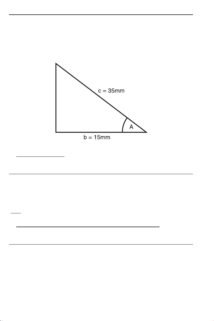
Example 1 — Cos A:
Solve for the unknown angle A if the two known sides are:
Side b = 15 mm
Side c = 35 mm
a) Longhand Method
: In this case, use the trigonometry formula:
Cos = Adjacent/Hypotenuse or cos A = b/c
KEYSTROKE DISPLAY
o o 0.
1 5* ÷ 3 5 = Ç ç 64.62307°
(64.6°)
Ç • DMS 64.37.23
*Note: you do not have to label mm.
b) Alternative Method (Use Pythagorean Theorem Keys):
Insert values into x, y, or r keys to solve for Theta.
KEYSTROKE DISPLAY
o o 0.
1 5 R X 15.
3 5 d R 35.
p 64.62307°
(64.6°)
Ç • DMS 64.37.23
USER’S GUIDE — 43
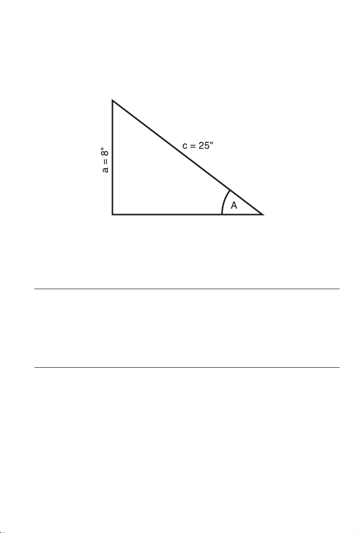
Trig Examples (Cont’d)
Example 2 — Sin A:
Solve angle A of the offset below, if the two known sides are:
Side a = 8 Inches
Side c = 25 Inches
In this case, use the trigonometry formula:
Sin = Opposite/Hypotenuse or Sin A = a/c
a) Longhand/Use Sine Formula:
KEYSTROKE DISPLAY
o o 0.
8 ÷ 2 5 = Ç S 18.66292°
(18.7°)
b) Use Pythagorean Theorem Keys:
KEYSTROKE DISPLAY
o o 0.
8 r Y 8.
2 5 d R 25.
p /
_
Ø 18.66292°
(18.7°)
44 — S
HEET METAL/HVAC PRO CALC
Trig Examples (Cont’d)
Example 3 — Tan A:
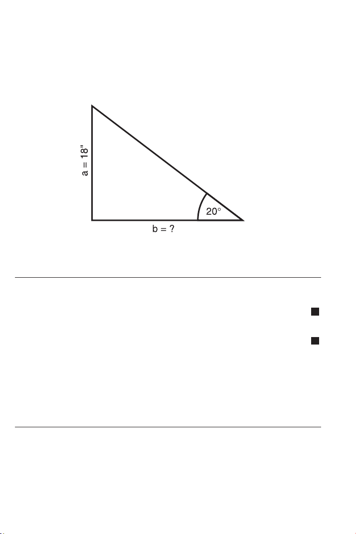
Find the length of the transition for a 20° angle:
Side a = 18 Inches
Side b = unknown
a) Longhand Method: Use Tan = Opposite/Adjacent
KEYSTROKE DISPLAY
1. First solve for Tan 20° to find ratio, then enter in Memory:
o o 0.
2 0 t µ M+ 0.36397
2. Solve for Side b by dividing Side a by stored ratio:
1 8 ÷ ® µ = 49.45459
(49.5 inches)
3. Clear Memory and clear display:
® ® o 0.
b) Use Pythagorean Theorem Keys:
KEYSTROKE DISPLAY
o o 0.
1 8 r Y 18.
2 0 p /
_
Ø 20.°
R X 49.45459
(49.5 inches)
M
M

USER’S GUIDE — 45
Converting Pitch to Angle/Tangent
Find the angle and corresponding Tangent for a roof with an 8/12
Pitch:
KEYSTROKE DISPLAY
1. Enter Pitch:
o o 0.
8 i p PTCH 8 INCH
2. Convert Pitch to degrees:
p /
_
Ø 33.69007°
3. Find Tangent or slope:
p p 0.666667
D:M:S EXAMPLE
Converting Degrees:Minutes:Seconds
Convert 23°42’39” to Decimal Degrees:
KEYSTROKE DISPLAY
o o 0.
2 3 • 4 2 • 3 9 DMS 23.42.39
Ç • (degrees) 23.71083°
Convert 44.29° to degrees:minutes:seconds format:
KEYSTROKE DISPLAY
o o 0.
4 4 • 2 9 Ç • (d:m:s) DMS 44.17.24
Note: Improperly formatted entries will be redisplayed in the correct convention after
any
operator key is pressed. For example, 30°89’ entered will be corrected and dis-
played as 31°29’ 0” or 31.48333°.

46 — S
HEET METAL/HVAC PRO CALC
VELOCITY PRESSURE / VELOCITY EXAMPLES
The Velocity Pressure/Velocity function uses an entered value to
calculate these four values:
1. Velocity (FPM) Number entered is assumed to be
Velocity Pressure
2. Velocity (Pressure) Number entered is assumed to be
Velocity (FPM)
3. Metric Velocity (MPS) Number entered is assumed to be
Metric Velocity Pressure (kPA)
4. Metric Velocity Pressure Number entered is assumed to be
(kPA) Metric Velocity (MPS)
The first time you perform this function, the values are displayed in
the order identified above. Subsequent calculations begin with the
last displayed value.
Converting Velocity Pressure to FPM
After obtaining Velocity Pressures (VP) from taking a traverse, your
calculator easily converts to Feet per Minute (FPM).
For example, convert the following VPs to FPM:
0.049”
0.123”
0.027”
KEYSTROKE DISPLAY
1. Enter first VP and convert to FPM:
o o 0.
• 0 4 9 Ç 0* FPM 886.5445
2. Enter second VP and convert to FPM:
• 1 2 3 Ç 0 FPM 1404.608
3. Enter third VP and convert to FPM:
• 0 2 7 Ç 0 FPM 658.0887
*The VP
ß ©
FPM function begins with the last displayed value. If FPM is not displayed
with the first press of Ç 0, continue pressing 0 until FPM is displayed.

USER’S GUIDE — 47
Converting FPM to Velocity Pressure
Calculate the Velocity Pressure (Imperial and Metric) if the FPM is
500:
KEYSTROKE DISPLAY
1. Enter 500 FPM to calculate Velocity:
o o 0.
5 0 0 Ç 0 FPM 89554.52
2. Calculate Velocity Pressure (VP):
0* VP 0.015586
3. Calculate Metric Velocity (MPS):
0 MPS 29.06888
4. Calculate Metric Velocity Pressure (KPA):
0 KPA 147928.99
5. Re-display entered value:
0 500.
*The VP
ß ©
FPM function begins with the last displayed value. If FPM is not dis-
played with the first press of Ç 0, continue pressing 0 until FPM is displayed.
Note
: The entered value is used to calculate all four values; for calculation of Velocity
(FPM), the entered value is assumed to be VP, and for calculation of VP, the entered
value is assumed to be FPM. For calculation of MPS, the entry is assumed to be kPA,
and for calculation of kPA, the entry is assumed to be MPS.
48 — S
HEET METAL/HVAC PRO CALC
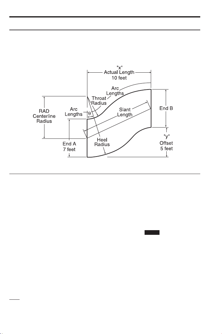
OFFSET EXAMPLES
Offset, Basic Example
If an offset is 5 Feet, the actual Length 10 Feet, and the Height of
the “end A” equal to 7 Feet, calculate the Centerline Radius,
Wrapper Length, Heel Radius, Throat Radius, and Theta.
KEYSTROKE DISPLAY
1. Enter actual Length as “x”:
o o 0.
1 0 f R X 10 FEET 0 INCH
2. Enter offset Length as “y”:
5 f r Y 5 FEET 0 INCH
3. Enter Height of “end A” as “a”:
7 f Ç 4 A 7 FEET 0 INCH
4. Calculate Centerline Radius, Wrapper Length, Heel Radius,
Throat Radius and Theta:
Ç ( RAD 6 FEET 3 INCH
( WL 11 FEET 7-1/8 INCH
( HEEL 9 FEET 9 INCH
( THRT 2 FEET 9 INCH
( THET 26.56505°
Note: If the calculated Throat Radius is less than zero, an error will be displayed (i.e.
“THRT Error”) when attempting to calculate the Offset.
STORED
USER’S GUIDE — 49
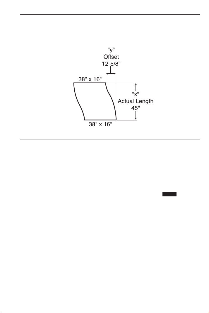
OGEE Offset in Feet-Inch-Fractions
If an offset is 12-5/8 Inches, the actual Length 45 Inches, and the
Height of the “end A” is 38 Inches, calculate the Centerline Radius,
Wrapper Length, Heel Radius, Throat Radius, and Theta.
KEYSTROKE DISPLAY
1. Enter actual Length as “x”:
o o 0.
4 5 i R X 45 INCH
2. Enter offset Length as “y”:
1 2 i 5 / 8 r Y 12-5/8 INCH
3. Enter Height of “end A” as “a”:
3 8 i Ç 4 A 38 INCH
4. Calculate Centerline Radius, Wrapper Length, Heel Radius,
Throat Radius and Theta:
Ç ( RAD 43-1/4 INCH
( WL 47-5/16 INCH
( HEEL 62-1/4 INCH
( THRT 24-1/4 INCH
( THET 15.67176°
STORED
50 — S
HEET METAL/HVAC PRO CALC
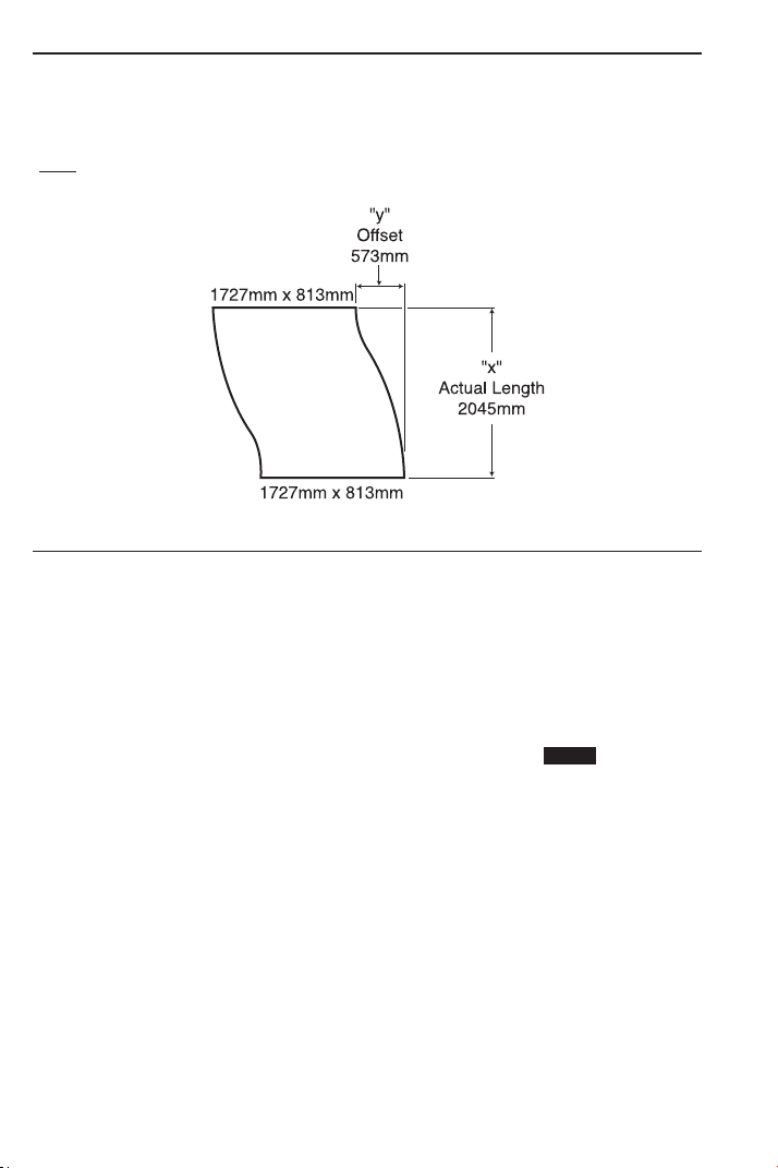
OGEE Offset, in Millimeters
If an offset is 573 Millimeters (mm), the actual Length 2045 mm, and
the Height of the “end A” 1727 mm, calculate the Centerline Radius,
Wrapper Length, Heel Radius, Throat Radius, and Theta.
*Note: To save keystrokes, you do not have to label entries in mm.
KEYSTROKE DISPLAY
1. Enter actual Length as “x”:
o o 0.
2 0 4 5 Ç m R X 2045. MM
2. Enter offset Length as “y”:
5 7 3 Ç m r Y 573. MM
3. Enter Height of “end A” as “a”:
1 7 2 7 Ç m Ç 4 A 1727. MM
4. Calculate Centerline Radius, Wrapper Length, Heel Radius,
Throat Radius and Theta:
Ç ( RAD 1967.868 MM
(1968 MM)
( WL 2150.408 MM
(2150 MM)
( HEEL 2831.368 MM
(2831 MM)
( THRT 1104.368 MM
(1104 MM)
( THET 15.65264°
STORED
USER’S GUIDE — 51
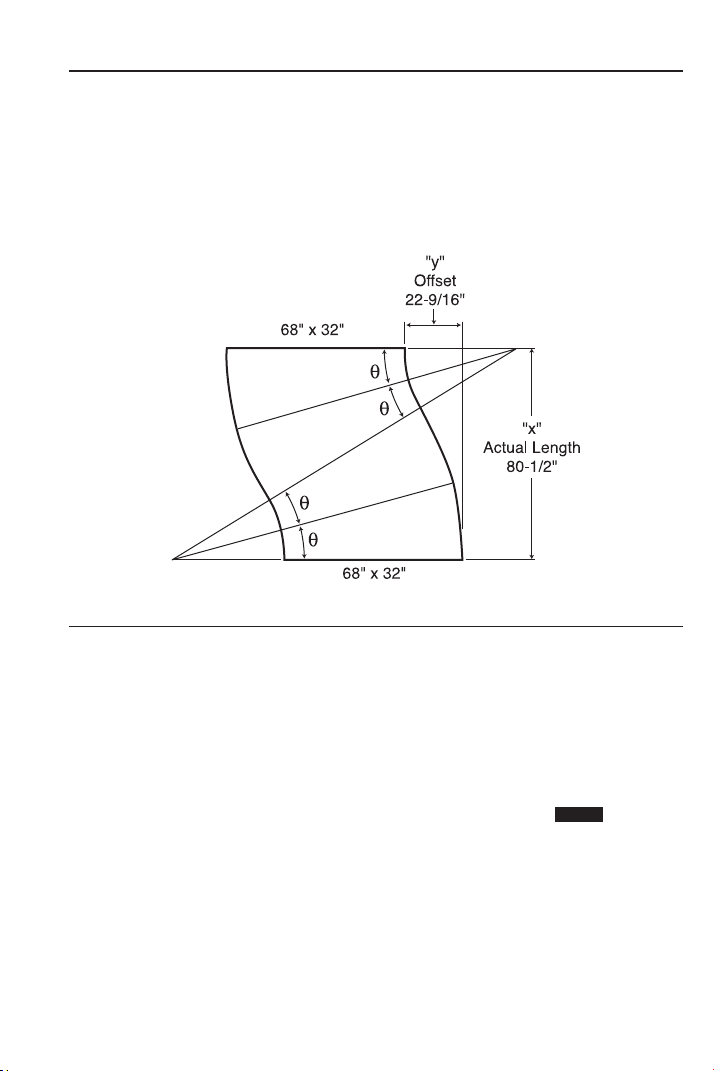
Dividing Offset into Multiple Degreed Elbows for Manageable
Sections
Solve the offset using the given variables:
Actual Length “x”: 80-1/2 Inches
Offset Length “y”: 22-9/16 Inches
A: 68 inches
Then, divide Theta into four degreed elbows; double Theta for two
equal elbows.
KEYSTROKE DISPLAY
1. Enter actual Length as “x”:
o o 0.
8 0 i 1 / 2 R X 80-1/2 INCH
2. Enter offset Length as “y”:
2 2 i 9 / 1 6 r Y 22-9/16 INCH
3. Enter Height of “way end A” as “a”:
6 8 i Ç 4 A 68 INCH
(Cont’d)
STORED

52 — SHEET METAL
/HVAC PRO CALC
(Cont’d)
KEYSTROKE DISPLAY
4. Calculate Centerline Radius, Wrapper Length, Heel Radius,
Throat Radius and Theta:
Ç ( RAD 77-7/16 INCH
( WL 84-5/8 INCH
( HEEL 111-7/16 INCH
( THRT 43-7/16 INCH
( THET 15.6571°
5. Convert Theta to degrees:minutes:seconds:*
Ç •
6. Multiply by two to double offset:**
x 2 =
DMS 15.39.25
DMS 31.18.51
*The angle of Thet
a can be used to divide the offset into degreed elbows for more
manageable sections. If the angle calculated is used, there would be four (4) elbows
each at 15°39’25”.
**If two (2) elbows were desired, the calculated angle can be doubled (each elbow
would be 31°18’51”). Doubling Theta provides the maximum elbow size for this offset
and radius combination. The total angle on either side of center can be divided into as
many elbows as is required to make the offset manageable. In the case above, the
maximum angle that can be divided is 31°18’51”.
USER’S GUIDE — 53
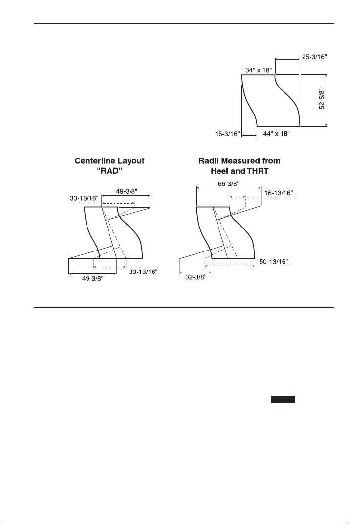
Change OGEE Offset
Solve the Change OGEE Offset below, with Wrapper Size transitions
from one end to another.
A) Solve Using:
a. Actual Length “x”: 52-5/8 Inches
b. Offset “y”: 15-3/16 Inches
c. End “a”: 34 Inches
KEYSTROKE DISPLAY
1. Enter actual Length as “x”:
o o 0.
5 2 i 5 / 8 R X 52-5/8 INCH
2. Enter offset Length as “y”:
1 5 i 3 / 1 6 r Y 15-3/16 INCH
3. Enter Height of “way end A” as “a”:
3 4 i Ç 4 A 34 INCH
4. Calculate Centerline Radius, Wrapper Length, Heel Radius,
Throat Radius and Theta:
Ç ( RAD 49-3/8 INCH
( WL 55-1/2 INCH
( HEEL 66-3/8 INCH
( THRT 32-3/8 INCH
( THET 16.09806°
STORED

54 — S
HEET METAL/HVAC PRO CALC
B) Solve Using:
a. Actual Length “x”: 52-5/8 Inches
b. Offset “y”: 25-3/16 Inches
c. End “a”: 34 Inches
KEYSTROKE DISPLAY
1. Enter actual Length as “x”:
o o 0.
5 2 i 5 / 8 R X 52-5/8 INCH
2. Enter offset Length as “y”:
2 5 i 3 / 1 6 r Y 25-3/16 INCH
3. Enter Height of “end A” as “a”:
3 4 i Ç 4 A 34 INCH
4. Calculate Centerline Radius, Wrapper Length, Heel Radius,
Throat Radius and Theta:
Ç ( RAD 33-13/16
INCH
( WL 60-5/16 INCH
( HEEL 50-13/16 INCH
( THRT 16-13/16 INCH
( THET 25.57682°
“WL”, or the Wrapper, corresponds to the side of the fitting associat-
ed with the offset dimension used for the calculation. The longest
Wrapper corresponds to the side with the largest offset (y).
Caution: When working with a “Change Transitional OGEE
Offset” (Wrapper size transitions from one end to other) the length
of a cheek having a slant length must be adjusted to include
that slant length prior to the calculations above taking place.
STORED

USER’S GUIDE — 55
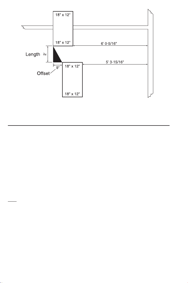
LAW OF COSINES EXAMPLES
Field Measuring for Ductwork Using the Law of Cosines —
Introduction
Dimensions taken when measuring objects in the field are taken
from the plan or horizontal plane and the elevation or vertical plane
of the objects. The purpose is to find the dimensional relationship of
distance and alignment between two or more objects. In the Sheet
Metal Industry, these specific dimensions are identified as Length,
Offset, and Angle.
Relationships can be established between any two objects such as
ductwork, structural, penetrations, units or terminal devices. The
objects are not as important as an understanding of the information
required to achieve the ultimate goal of “the ability to develop the
required fittings and/or parts for the system.”
Example:
Two duct lines, both 18 Inches x 12 Inches as shown in the sketch
on the next page, are to be measured for a fill-in piece. Measurements
of the plan view or horizontal plane are taken from both ducts to a
parallel stationary object such as a wall or a structural member. The
difference between these two measurements establishes the hori-
zontal offset between the two duct lines, if any exists. The process is
repeated for the elevation measurements typically using the floor
below the objects (upper at 8 Feet 8 Inches, the lower 8 Feet 10-
9/16 Inches). A measurement between the two duct lines will estab-
lish length. These measurements and calculations are used to devel-
op the duct and/or fittings required to fill the space.
Using this method we find the fill-in piece will need to be 24 Inches
in length with a 9 Inch horizontal offset and a 2-9/16 Inches vertical
offset.
56 — SHEET METAL/HV
AC PRO CALC
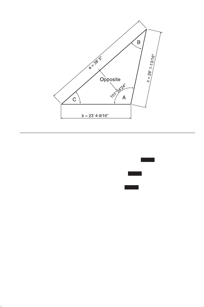
Non-90 Degree Triangle Measurement Using Law of Cosines
and Heron’s Theorem
The Law of Cosines keys calculate the unknown angles after
inputting the three known sides of a non-90 degree triangle. Triangle
area is also found given the built-in formula for Heron’s Theorem.
The relationship of
any side to the included angle is identified as the
angles opposite the side having the same letter designation (see
diagram on next page). When using this method of measuring, the
user needs to keep the relationship of the sides to their included
angles in perspective at all times. Because your calculator displays
all three angles, the user has the discretion of identifying as they
choose.
Note: As a test, rotate the letters used to identify the sides and corresponding angles
clockwise on the triangle on the next page, input the lengths in the appropriate key
location for the new letter and display the included angles. You’ll find that the Degree
of Angles are still in the same location in relationship to the Length of Sides as before,
only the letters used to identify those lengths and angles changed positions.
Using the lengths given below designated as Side a, b and c, calcu-
late the corresponding angles A, B and C.
Side a: 38 Feet 5 Inches
Side b: 23 Feet 4-9/16 Inches
Side c: 26 Feet 1-13/16 Inches
(Cont’d)
USER’S GUIDE — 57
(Cont’d)
KEYSTROKE DISPLAY
1. Enter side a, b and c:
o o 0.
3 8 f 5 i Ç 4
A 38 FEET 5 INCH
2 3 f 4 i 9 / 1 6 Ç 5
B 23 FEET 4-9/16 INCH
2 6 f 1 i 1 3 / 1 6 Ç 6
C 26 FEET 1-13/16 INCH
2. Calculate Angle A, B and C:
Ç 9 /
_
A 101.5734°
9 /
_
B 36.59978°
9 /
_
C 41.8268°
3. Calculate Triangle area:
9 AREA 299.4929 SQ FEET
STORED
STORED
STORED
58 — S
HEET METAL/HVAC PRO CALC
Using Law of Cosines and Pythagorean Theorem to Calculate
Offset, Length, and Angle
In field measuring, Offset, Length and Angle are the essential dimen-
sions to the design and fabrication of the components required to fill
in between objects. In some cases, no structural objects are within
reach or parallel to the objects to be measured, so other methods of
measuring are required. In this method, a Triangle is formed to
establish the relationship between the objects. For the sake of
identification, this Triangle, which is physically measured, will be called
“The Measured Triangle,” or Triangle “I” below, with given dimensions.
Length and Offset form a Right Angle to each other, so Triangle
“II”, a Right Triangle, is used to calculate these dimensions.
Note: “x” or “y” can represent either Offset or Length, the order dictated by the initial
setup and perspective. In the setup, placement of the Right Triangle should always
allow for the angle of “θ” in Triangle “II” to be established by simple subtraction of
angle “A
0
” from a known angle like 180°, as in the example below.
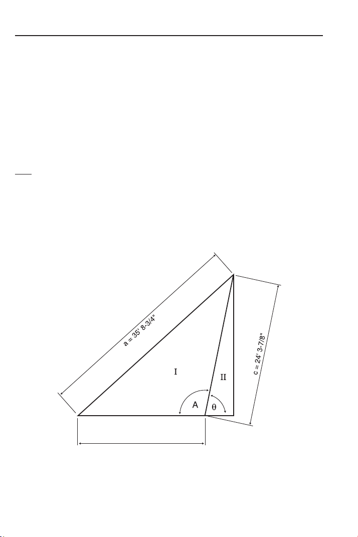
Find Theta θ, “x,” and “y,” if the sides of the Measured Triangle “I”
are: 35 Feet 8-3/4 Inches, 21 Feet 8-15/16 Inches, and 24 Feet
3-7/8 Inches. See diagram below.
(Cont’d)
b = 21' 8-15/16"

USER’S GUIDE — 59
(Cont’d)
KEYSTROKE DISPLAY
1. Enter side a, b and c:
o o 0.
3 5 f 8 i 3 / 4 Ç 4 A 35 FEET 8-3/4 INCH
2 1 f 8 i 1 5 / 1 6 Ç 5
B 21 FEET 8-15/16 INCH
2 4 f 3 i 7 / 8 Ç 6 C 24 FEET 3-7/8 INCH
2. Calculate and input Theta by subtracting Angle “A” (found by the
Law of Cosines) from known angle of 180°:
1 8 0 – Ç 9 /
_
A 101.5687°
= 78.43128 (Theta θ)
p /
_
Ø 78.43128°
3. Recall stored “c” and input as “r” the Hypotenuse:
® 6 = d R 24 FEET 3-7/8 INCH
4. Calculate “x”:
R X 4 FEET 10-9/16 INCH
5. Calculate “y”:
r Y 23 FEET 9-15/16 INCH
Sheet Metal Panels for an Irregular Hip Roof
A contractor is going to cover one end of an Irregular Hip Roof with
sheet metal panels. The length of the roof along the eave is 98 Feet
5-1/4 Inches, the length along the left hip is 38 Feet 10-11/16
Inches, and the length along the right hip is 73 Feet 1-1/8 Inches.
Find the angles between the roof edges.
KEYSTROKE DISPLAY
1. Enter lengths:
9 8 f 5 i 1 / 4 Ç 4 A 98 FEET 5-1/4 INCH
3 8 f 1 0 i 1 1 / 1 6 Ç 5
B 38 FEET 10-11/16 INCH
7 3 f 1 i 1 / 8 Ç 6 C 73 FEET 1-1/8 INCH
2. Calculate the angles between the roof edges:
Ç 9 /
_
A 119.9081°
9 /
_
B 20.02713°
9 /
_
C 40.06473°
9 AREA 1232.046 SQ FEET
STORED
STORED
STORED
STORED
STORED
STORED
60 — S
HEET METAL/HVAC PRO CALC
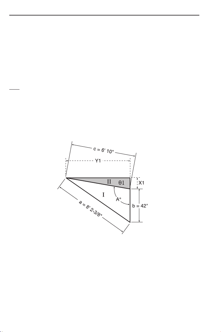
Inline Duct, Single Offset (Computing Offset, Length, and Angle)
When working with the process of direct measure between two ducts
#1 and #2, as diagramed below, one leg of “The Measured Triangle”
“I” should use the larger horizontal dimension of the two ducts.
Therefore, in this scenario, the 42 Inches dimension of duct #2 is
used since it is the larger of the two ducts.
To calculate the angle A
0
in “The Measured Triangle” “I” and the
dimensions of θ1, X1, and Y1 in triangle “II,” follow the sequence of
input given below to solve for the dimensions in question.
Note: “x” or “y” can represent either Offset or Length, the order dictated by the initial
setup and perspective. In the setup, placement of the Right-Triangle should always
allow for the angle of “ θ” in triangle “II” to be established by simple subtraction of
angle “A
0
” from a known angle like 180°, as in the example below.
Find Theta θ, “x”, and “y” if the sides of the Measured Triangle “I”
are: 8 Feet 2-3/8 Inches, 42 Inches, and 6 Feet 10 Inches. See
diagram below.
(Cont’d)
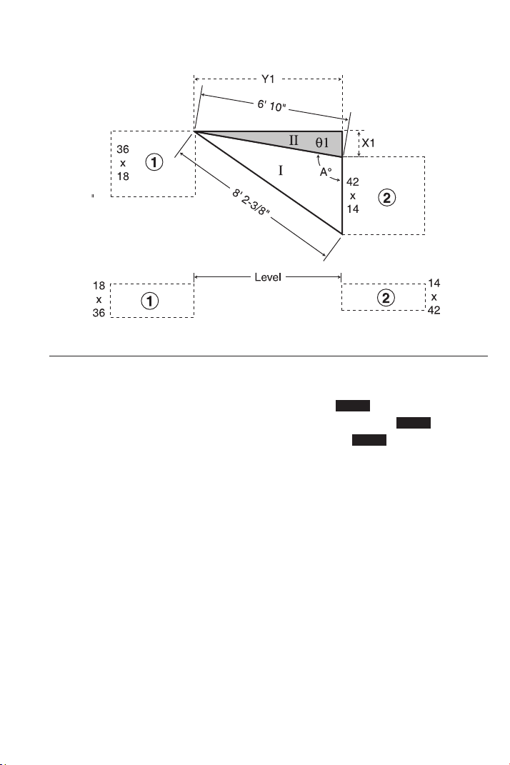
USER’S GUIDE — 61
(Cont’d)
KEYSTROKE DISPLAY
1. Enter side a, b, and c:
o o 0.
8 f 2 i 3 / 8 Ç 4 A 8 FEET 2-3/8 INCH
4 2 i Ç 5 B 42 INCH
6 f 1 0 i Ç 6 C 6 FEET 10 INCH
2. Calculate and input Theta by subtracting Degree “A” (found by the
Law of Cosines) from known angle of 180°:
1 8 0 – Ç 9 /
_
A 99.94554°
= 80.05446 (Theta θ)
p /
_
Ø 80.05446°
3. Recall stored “c” and input as “r”:
® 6 = d R 6 FEET 10 INCH
4. Calculate “x”:
R X 1 FEET 2-3/16 INCH
5. Calculate “y”:
r Y 6 FEET 8-3/4 INCH
STORED
STORED
STORED
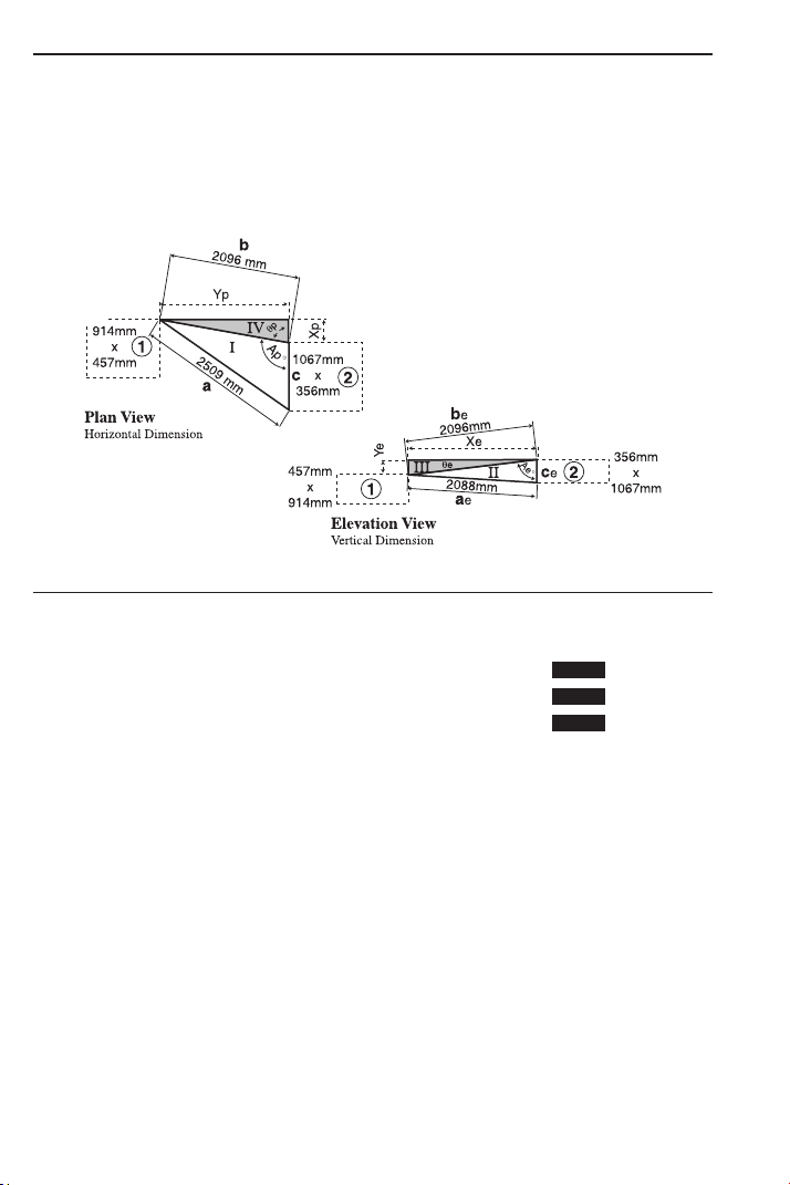
Inline Duct, Double Offset (Computing Offset, Length and Angle)
This example (see diagrams below) depicts two ducts offsetting both
in the horizontal and vertical planes. Basic procedures are the same
as those followed in the previous example, except a correction to
the calculated length will be required at triangle “V”.
A) Input “Measured Triangle I” to find Triangle IV:
KEYSTROKE DISPLAY
1. Enter side a, b, and c:
o o 0.
2 5 0 9 Ç m Ç 4 A 2509. MM
2 0 9 6 Ç m Ç 5 B 2096. MM
1 0 6 7 Ç m Ç 6 C 1067. MM
2. Calculate and input Theta by subtracting Degree “A” (found by the
Law of Cosines) from known angle of 180°:
1 8 0 – Ç 9 /
_
A 99.82668°
= 80.17332 (Theta θ)
p /
_
Ø 80.17332°
3. Recall stored “b”* and input as “r”:
® 5 = d R 2096. MM
4. Calculate “x”:
R X 357.7207 MM
5. Calculate “y”:
r Y 2065.249 MM
*The calculated dimension of “Yp”
is a slant length on the same plane as line “b” in the
elevation view. The actual length is found by forming a Right Triangle (see Triangle V).
62 — SHEET METAL/HVAC PRO CALC
STORED
STORED
STORED

USER’S GUIDE — 63
B) Input “Measured Triangle II” to find Triangle III:
KEYSTROKE DISPLAY
1. Enter side a, b, and c:
o o 0.
2 0 8 8 Ç m Ç 4 A 2088. MM
2 0 9 6 Ç m Ç 5 B 2096. MM
3 5 6 Ç m Ç 6 C 356. MM
2. Calculate and input Theta by subtracting Degree “A” (found by the
Law of Cosines) from known angle of 90° (in this case, the Triangles
form a Right Triangle):
9 0 – Ç 9 /
_
A 83.83727°
= 6.162732 (Theta θ)
p /
_
Ø 6.162732°
3. Recall stored “b” and input as “r”:
® 5 = d R 2096. MM
4. Calculate “x”:
R X 2083.887 MM
5. Calculate “y”:
r Y 225.0112 MM
STORED
STORED
STORED
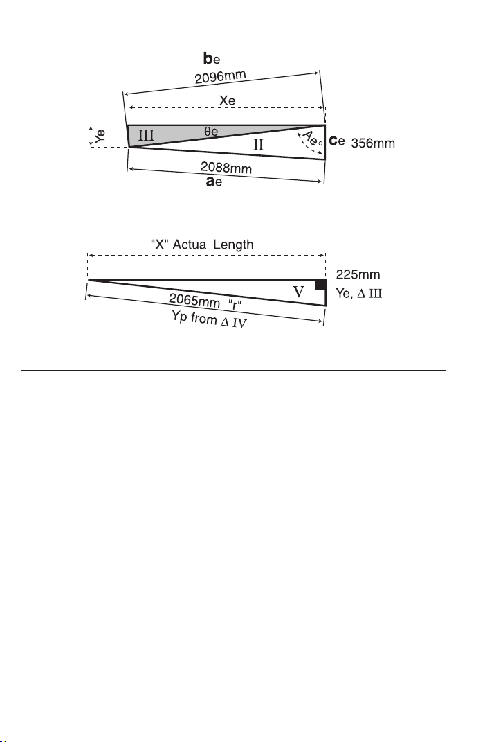
64 — S
HEET METAL/HVAC PRO CALC
C) Input Triangle V to Find Actual Length Between the Objects:
KEYSTROKE DISPLAY
1. Enter “y” from Triangle IV and enter as “r” (the Hypotenuse):
o o 0.
2 0 6 5 Ç m d R 2065. MM
2. Enter “y” from Triangle III and enter as “y”:
2 2 5 Ç m r Y 225. MM
3. Calculate “x” for the Actual Length between the objects:
R X 2052.706 MM
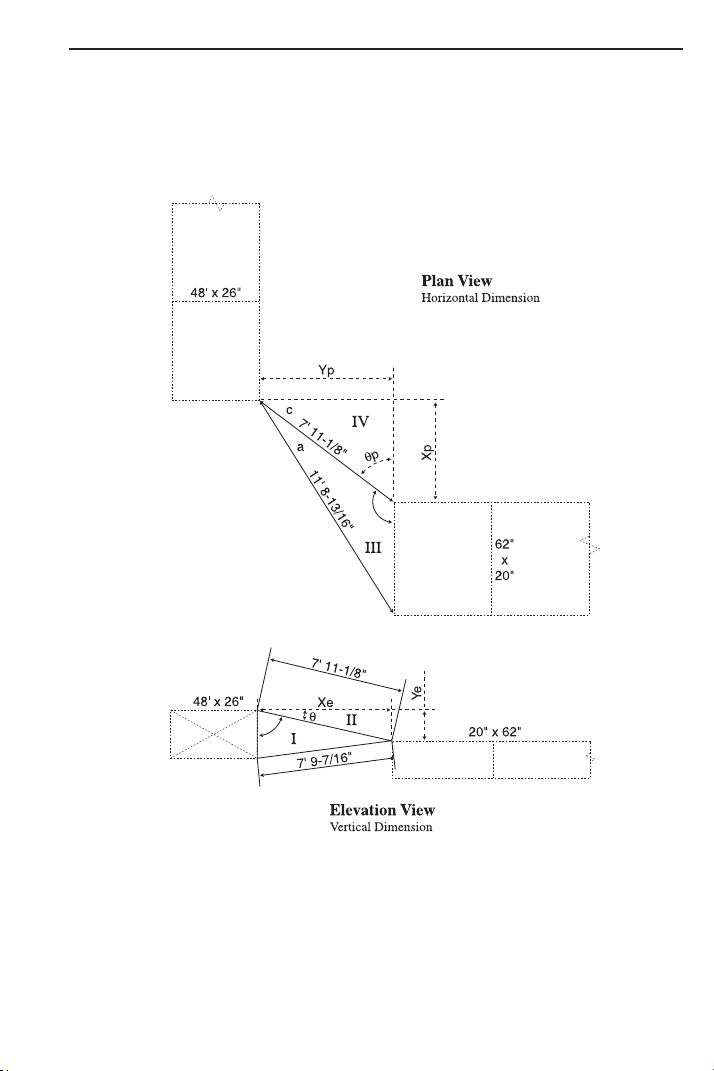
USER’S GUIDE — 65
Objects at Right Angles
When you are working with objects at Right Angles, set up the
“Measured Triangles” and subsequent calculations in the same man-
ner as the previous inline objects. Due to the vertical misalignment
of the two ducts, the added step of finding the actual length will
be required.
With the exception of the duct dimensions the measured lengths of
Triangle III are slant lengths. Therefore, if the calculations are
processed using these dimensions the results would also be slant
lengths. To find the actual lengths for “Yp” and “Xp” requires the
erection of two true length Triangles. The true length Triangles will
utilize “Ye” from the elevation offset as the “Y” leg of both triangles
and the measured lengths of “a” and “c” as the “r” legs.
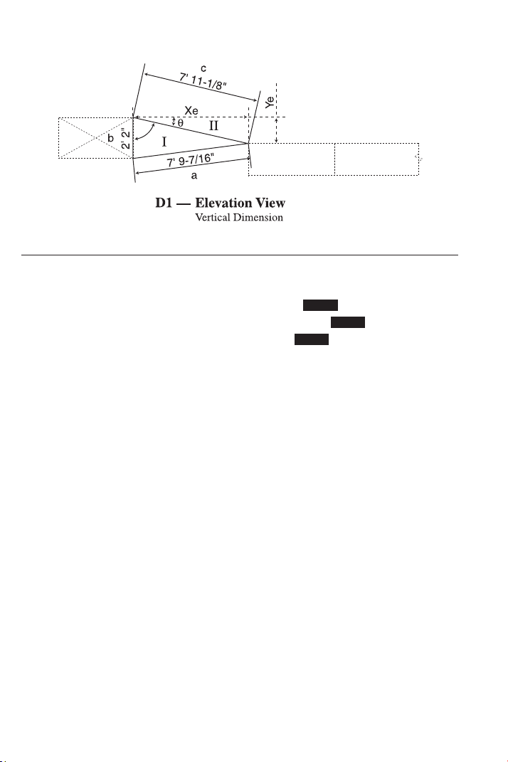
66 — S
HEET METAL/HVAC PRO CALC
1) Find the elevation offset “Ye” and the actual length “Xe” in D1:
KEYSTROKE DISPLAY
1. Enter sides a, b, and c:
o o 0.
7 f 9 i 7 / 1 6 Ç 4 A 7 FEET 9-7/16 INCH
2 f 2 i Ç 5 B 2 FEET 2 INCH
7 f 1 1 i 1 / 8 Ç 6 C 7 FEET 11-1/8 INCH
2. Calculate and input Theta by subtracting Degree “A” (found by the
Law of Cosines) from Right Angle of 90°:
9 0 – Ç 9 /
_
A 78.40512°
= 11.59488
(Theta θ)
p /
_
Ø 11.59488°
3. Recall stored slant length “c” and input as “r”:
® 6 = d R 7 FEET 11-1/8 INCH
4. Calculate elevation offset “Ye”:
r Y 1 FEET 7-1/8 INCH
5. Calculate actual length “Xe”:
R X 7 FEET 9-3/16 INCH
STORED
STORED
STORED
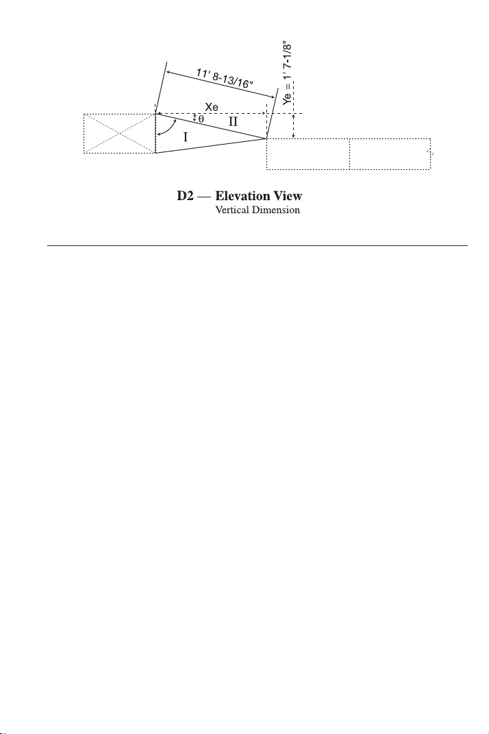
USER’S GUIDE — 67
2) Find actual length “Xe” in D2:
KEYSTROKE DISPLAY
1. Enter slant length as “r”:
o o 0.
1 1 f 8 i 1 3 / 1 6 d
R
11 FEET 8-13/16 INCH
2. Enter calculated elevation offset from D1 as “y”:
1 f 7 i 1 / 8 r Y 1 FEET 7-1/8 INCH
3. Calculate actual length “Xe” in D2:
R X 11 FEET 7-1/2 INCH
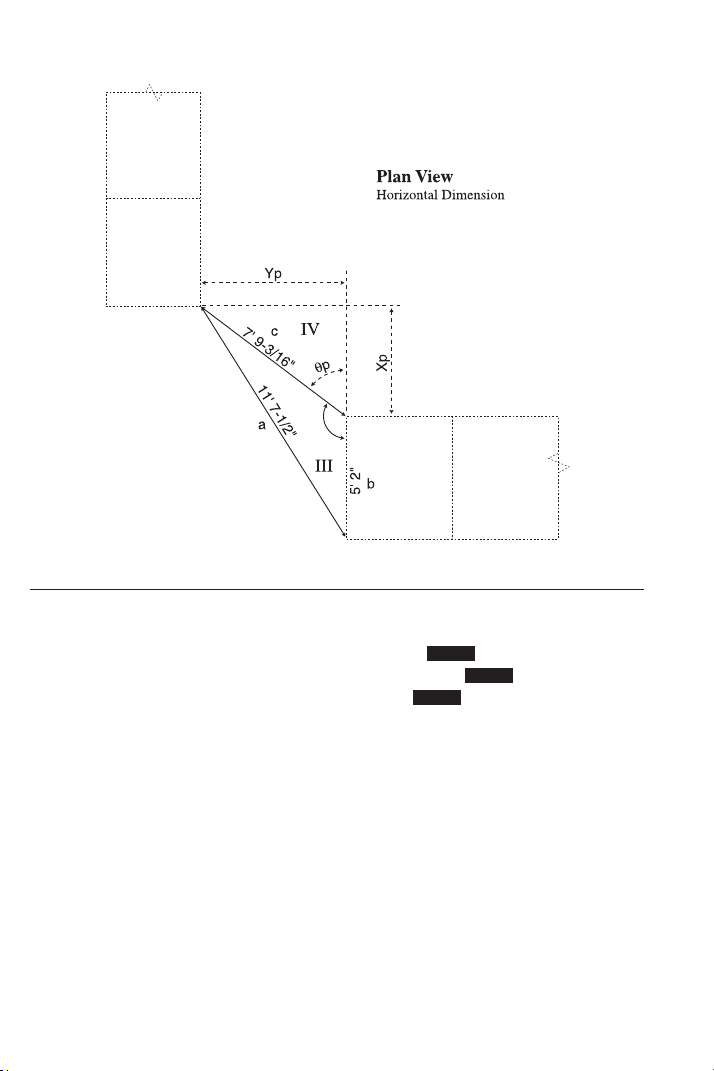
68 — S
HEET METAL/HVAC PRO CALC
3) Find the horizontal length ”Xp” between the objects and the hori-
zontal offset “Yp” between the objects:
KEYSTROKE DISPLAY
1. Enter sides a, b and c:
o o 0.
1 1 f 7 i 1 / 2 Ç 4 A 11 FEET 7-1/2 INCH
5 f 2 i Ç 5 B 5 FEET 2 INCH
7 f 9 i 3 / 1 6 Ç 6 C 7 FEET 9-3/16 INCH
2. Calculate and input Theta by subtracting Degree “A” (found by the
Law of Cosines) from 180°:
1 8 0 – Ç 9 /
_
A 126.8649°
= 53.13512
(Theta θ)
p /
_
Ø 53.13512°
3. Recall stored “c” and input as “r”:
® 6 = d R 7 FEET 9-3/16 INCH
4. Calculate horizontal length “Xp” between the objects:
R X 4
FEET 7-7/8 INCH
5. Calculate horizontal offset “Yp” between the objects:
r Y 6 FEET 2-9/16 INCH
STORED
STORED
STORED
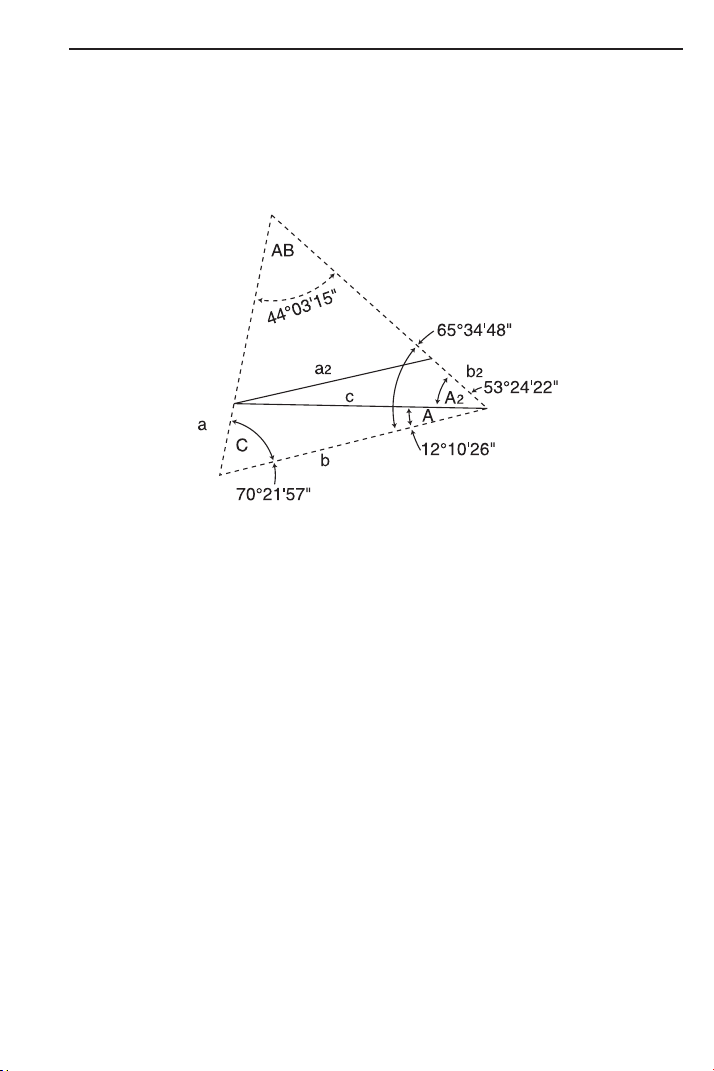
USER’S GUIDE — 69
Calculating Angles Between Objects (“Angle Between”)
The Triangle, having a total of 180°, is the basic logic used to solve
for the angle between two objects. To accomplish this task, two
measurable Triangles are established between the objects for the
purpose of finding the angles C, A, and A2, as indicated in the
example below. Subtracting the sum of Angles C, A, and A2 from
180° gives us the “Angle Between” the two objects.
The calculations to solve for the next application are based on the
dimensions being slant lengths as it would be in any dimensions
actually taken in the field. The actual length must be established
prior to finding the “Angle Between” (AB).
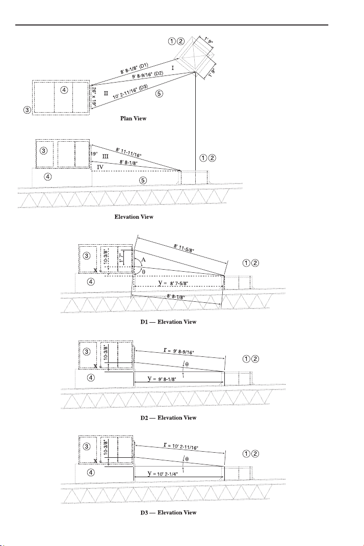
70 — S
HEET METAL/HVAC PRO CALC
Calculating Angles Between Objects Example
LEGEND
1 Existing Roof Curb
to remain.
2 New 20’ x 20’ duct
down through Roof
Curb to system below.
3 New Roof Top Furnace
with integral curb.
4 Field measure duct
required from the
existing roof to new
Roof Top Furnace.
5 Existing Roof Drain
to remain.
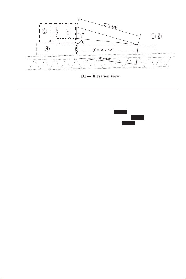
USER’S GUIDE — 71
1) Find actual length “y” between objects in D1:
KEYSTROKE DISPLAY
1. Enter side a, b, and c:
o o 0.
8 f 1 1 i 1 1 / 1 6 Ç 4
A 8 FEET 11-11/16 INCH
1 f 7 i Ç 5 B 1 FEET 7 INCH
8 f 8 i 1 / 8 Ç 6 C 8 FEET 8-1/8 INCH
2. Calculate and input Theta by subtracting Degree “A” (found by
the Law of Cosines) from known angle of 180°:
1 8 0 – Ç 9 /
_
A 95.70871°
= 84.29129 (Theta θ)
p /
_
Ø 84.29129°
3. Recall stored “c” and input as “r”:
® 6 = d R 8 FEET 8-1/8 INCH
4. Calculate “x”:
R X 0 FEET 10-3/8 INCH
5. Calculate “y”, or actual length:
r Y 8 FEET 7-5/8 INCH
STORED
STORED
STORED
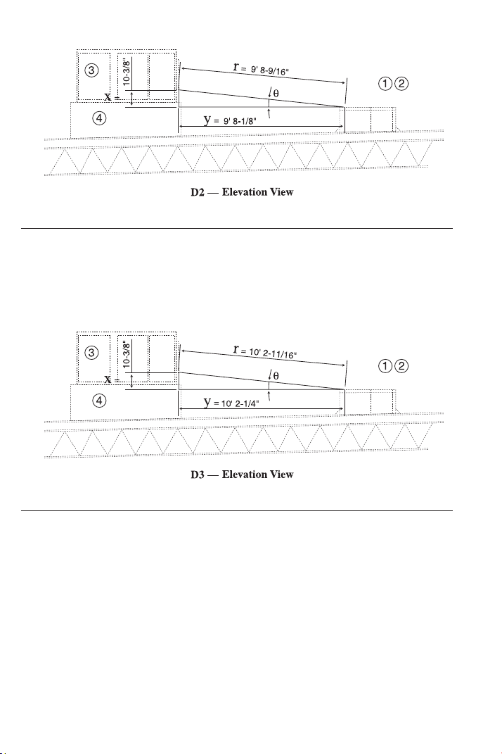
72 — S
HEET METAL/HVAC PRO CALC
2) Find actual length “y” between objects in D2:
KEYSTROKE DISPLAY
1 0 i 3 / 8 R X 10-3/8 INCH
9 f 8 i 9 / 1 6 d R 9 FEET 8-9/16 INCH
r Y 9 FEET 8-1/8 INCH
3) Find actual length “y” between objects in D3:
KEYSTROKE DISPLAY
1 0 i 3 / 8 R X 10-3/8 INCH
1 0 f 2 i 1 1 / 1 6 d R 10 FEET 2-11/16 INCH
r Y 10 FEET 2-1/4 INCH
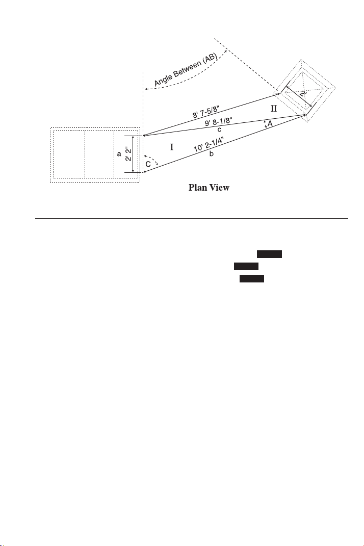
USER’S GUIDE — 73
4) Input Triangle I and find Angles A and C:
KEYSTROKE DISPLAY
1. Enter side a, b, and c:
o o 0.
2 f 2 i Ç 4 A 2 FEET 2 INCH
1 0 f 2 i 1 / 4 Ç 5 B 10 FEET 2-1/4 INCH
9 f 8 i 1 / 8 Ç 6 C 9 FEET 8-1/8 INCH
2. Use Law of Cosines to find Angle “A” and store in Memory 1:
Ç 9 /
_
A 12.17384°
= Ç 1 M-1 12.17384°
3. Use Law of Cosines to find Angle “C” and store in Memory 2:
Ç 9 9 9 /
_
C 70.36573°
= Ç 2 M-2 70.36573°
STORED
STORED
STORED
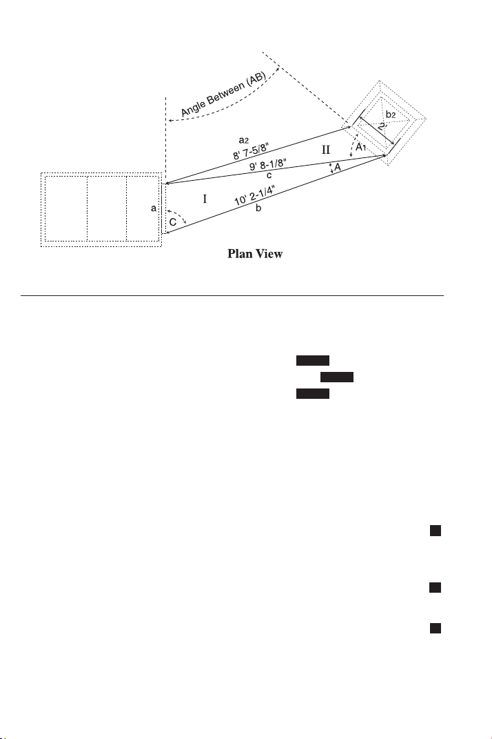
74 — S
HEET METAL/HVAC PRO CALC
5) Input Triangle II and find Angle A1 and the “Angle Between”:
KEYSTROKE DISPLAY
1. Enter side a2, b2, and recall c (“a2” was calculated as “y” in first
section; “c” is already stored):
o 0.
8 f 7 i 5 / 8 Ç 4 A 8 FEET 7-5/8 INCH
2 f Ç 5 B 2 FEET 0 INCH
® 6 C 9 FEET 8-1/8 INCH
2. Use Law of Cosines to find Angle “A2” and store in Memory 3:
Ç 9 /
_
A 53.40618°
= Ç 3 M-3 53.40618°
3. Recall M1, M2, and M3 and find total:
® 1 + ® 2 + ® 3 = 135.9458°
4. Add total to M+ (regular Memory):
µ M+ 135.9458°
5. Subtract above angle from known angle of 180° to find the Angle
Between objects (AB):
1 8 0 – ® µ = 44.05425
6. Convert to degrees:minutes:seconds:
Ç • DMS 44.03.15
7. Clear Memory and clear display:
® ® o 0.
M
M
M
STORED
STORED
STORED

USER’S GUIDE — 75
FAN LAW EXAMPLES
Fan Law 1
The formula for Fan Law 1 (built into this calculator) is:
Fan laws use the temporary storage registers a, b, a-new, and b-new.
Fan Law 1 calculates using the entry of the three known variables
and Ç R to calculate the unknown fourth value.
Example 1:
A 1,250 CFM fan is running at 750 RPM, but it needs to supply
1,400 CFM. What is the RPM required?
KEYSTROKE DISPLAY
1. Enter current CFM into “a” old:
o o 0.
1 2 5 0 Ç 4 A 1250.
2. Enter new CFM into “a-new”:
1 4 0 0 Ç 7 An 1400.
3. Enter current RPM into “b” old:
7 5 0 Ç 5 B 750.
4. Calculate new RPM or “b-new”:
Ç R RPMn FAN LAW1 840.
Example 2:
You set up
a fan with a VFD for 14,000 CFM running at 855 RPM.
You change the RPM to 1050. What is the new CFM?
KEYSTROKE DISPLAY
1. Enter current CFM into “a” old:
o o 0.
1 4 0 0 0 Ç 4 A 14000.
2. Enter current RPM into “b” old:
8 5 5 Ç 5 B 855.
3. Enter new RPM into “b-new”:
1 0 5 0 Ç 8 Bn 1050.
4. Calculate new CFM or “a-new”:
Ç R CFMn FAN LAW1 17192.98
STORED
STORED
STORED
STORED
STORED
STORED
where,
CFM = Feet
3
per Minute
RPM = Revolutions per Minute

76 — S
HEET METAL/HVAC PRO CALC
Fan Law 2
The formula for Fan Law 2 (built into this calculator) is:
Fan laws use the temporary storage registers a, b, a-new, and b-new.
Fan Law 2 calculates using the entry of the three known variables
and Ç r to calculate the unknown fourth value.
Example 1:
A fan is producing 15,300 CFM at 3.2” SP. If the fan is adjusted to
14,000 CFM, what will the new SP be?
KEYSTROKE DISPLAY
1. Enter current CFM into “a” old:
o o 0.
1 5 3 0 0 Ç 4 A 15300.
2. Enter new CFM into “a-new”:
1 4 0 0 0 Ç 7 An 14000.
3. Enter current SP into “b” old:
3 • 2 Ç 5 B 3.2
4. Calculate new SP or “b-new”:
Ç r SP
n FAN LAW2 2.679311
Example 2:
After doing a traverse, you find that the duct has 1850 CFM and a
SP of 1.2”. You adjust the zone dampers and take a new SP that is
0.83. What is the new CFM?
KEYSTROKE DISPLAY
1. Enter current CFM into “a” old:
o o 0.
1 8 5 0 Ç 4 A 1850.
2. Enter current SP into “b” old:
1 • 2 Ç 5 B 1.2
3. Enter new SP into “b-new”:
• 8 3 Ç 8 Bn 0.83
4. Calculate “a-new” or new CFM:
Ç r CFM
n FAN LAW2 1538.58
STORED
STORED
STORED
STORED
STORED
STORED
S
S
where,
SP = Static Pressure
CFM = Feet
3
per Minute

USER’S GUIDE — 77
Fan Law 3
The formula for Fan Law 3 (built into this calculator) is:
Fan laws use the temporary storage registers a, b, a-new, and b-new.
Fan Law 3 calculates using the entry of the three known variables
and Ç d to calculate the unknown fourth value.
Example 1:
A fan is running at 15,800 CFM using 6.3 BHP. If the CFM is
increased to 20,000 CFM, what is the new BHP?
KEYSTROKE DISPLAY
1. Enter current CFM into “a” old:
o o 0.
1 5 8 0 0 Ç 4 A 15800.
2. Enter new CFM into “a-new”:
2 0 0 0 0 Ç 7 An 20000.
3. Enter current BHP into “b” old:
6 • 3 Ç 5 B 6.3
4. Calculate new BHP or “b-new”:
Ç d BHPn FAN LAW 3 12.77789
Example 1 (a):
For the fan above, what is the maximum CFM if a ten HP motor is
used?
KEYSTROKE DISPLAY
1. Clear entered CFM in “a-new”:
0 Ç 7 An 0.
2. Enter new BHP into “b-new”:
1 0 Ç 8 Bn 10.
3. Calculate new maximum CFM or “a-new”:
Ç d CFMn FAN LAW 3 18430.77
STORED
STORED
STORED
STORED
STORED
where,
BHP = Brake Horsepower
CFM = Feet
3
per Minute

ARC / CIRCLE EXAMPLES
Arc Length — Degree and Diameter Known
Find the Arc length of an 85° portion of a Circle with a 5-Foot
Diameter:
KEYSTROKE DISPLAY
o o 0.
5 f C DIA 5 FEET 0 INCH
8 5 Ç C ARC 85.00°
C ARC 3 FEET 8-1/2 INCH
Arc Length — Degree and Radius Known
Find the Arc length of a Circle with a 24-Inch Radius and 77° of Arc
(77° of 360° Circle):
KEYSTROKE DISPLAY
o o 0.
2 4 i Ç p (Segment Radius) RAD 24 INCH
7 7 Ç C ARC 77.00°
C ARC 32-1/4 INCH
Using ArcK to Calculate an Arc Length
Using the ArcK constant (0.017453), calculate the Arc length given
100° of a one-unit Circle. The Radius is 5 Feet.
KEYSTROKE DISPLAY
1. Enter Degrees and multiply:
oo 0.
10 0x 100.
2. Enter Radius and multiply:
5f x 500 FEET 0 INCH
3. Recall ArcK:
Ç π ARCK 0.017453
4. Calculate Arc Length:
= 8 FEET 8-3/4 INCH
Note: ArcK is
equivalent to the constant of a 1° Arc angle for a one-unit value.
It may be multipled with a Unitless, Linear, Square or Cubic value. The formula for
ArcK is π/180.
78 — SHEET METAL/HVAC PRO CALC
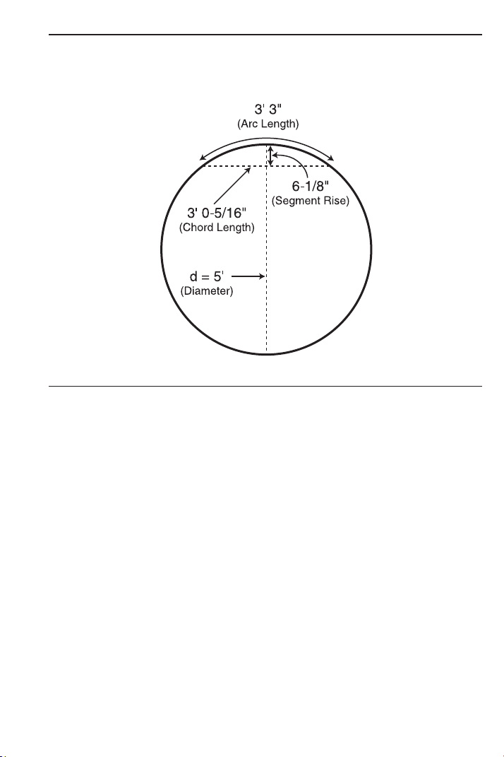
USER’S GUIDE — 79
Arc Calculations — Arc Length and Diameter Known
Find the Arc Degree, Chord Length, Rise, Segment and Pie Slice
Area, and Segment Rise, given a 5-Foot Diameter and an Arc length
of 3 Feet 3 Inches:
KEYSTROKE DISPLAY
1. Enter Circle Diameter (Note: enter Diameter into the C key):
o o 0.
5 f C DIA 5 FEET 0 INCH
2. Enter Arc Length:
3 f 3 i Ç C ARC 3 FEET 3 INCH
3. Find Degree of Arc:
C ARC 74.48451°
4. Find Chord Length:
C CORD 3 FEET 0-5/16 INCH
5. Find Segment Area:
C SEG 1.051381 SQ FEET
6. Find Pie Slice Area:
C PIE 4.0625 SQ FEET
7. Find Segment Rise:
C RISE 0 FEET 6-1/8 INCH

80 — S
HEET METAL/HVAC PRO CALC
Arched/Circular Rake-Walls — Chord Length and
Segment Rise Known
You’re building a Circular or Arched Rake-Wall. Given a Chord
Length of 15 Feet and a Rise of 5 Feet, find all Arc values and
lengths of the Arched walls. The On-Center spacing is 16 Inches.
KEYSTROKE DISPLAY
1. Enter Chord Length and Segment Rise:
o o 0.
1 5 f R RUN 15
FEET 0 INCH
5 f r RISE 5 FEET 0 INCH
2. Calculate Radius:
Ç p RAD 8 FEET 1-1/2 INCH
3. Find Arc Angle:
Ç C ARC 134.76º
4. Find Arc Length:
C ARC 19 FEET 1-5/16 INCH
5. Display entered Chord Length:
C CORD 15 FEET 0 INCH
6. Find Segment Area:
C SEG 54.19722 SQ FEET
7. Find Pie Slice Area:
C PIE 77.63472 SQ FEET
8. Display entered Segment Rise:
C RISE 5 FEET 0 INCH
9. Display stored On-Center spacing for the wall:
C OC 16 INCH*
(Cont’d)
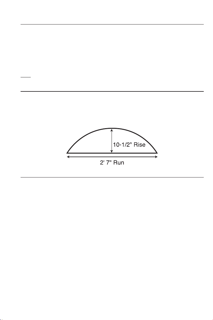
USER’S GUIDE — 81
(Cont’d)
KEYSTROKE DISPLAY
10. Find Arched wall stud lengths:
C AW1 4 FEET 10-11/16 INCH
C AW2 4 FEET 6-5/8 INCH
C AW3 3 FEET 11-3/8 INCH
C AW4 3 FEET 0-1/16 INCH
C AW5 1 FEET 6-1/4 INCH
Note: Successive presses of C will toggle to the beginning.
Arched Windows
Find the Radius of an Arched window with a Chord Length of 2 Feet
7 Inches and a Rise of 10-1/2 Inches. Then, find the Arc Angle, Arc
Length and Segment Area of the window.
KEYSTROKE DISPLAY
1. Enter Chord Length:
o o 0.
2 f 7 i R (Run) X 2 FEET 7 INCH
2. Enter Rise:
1 0 i 1 / 2 r (Rise) Y 10-1/2 INCH
3. Find Radius:
Ç p RAD 16-11/16 INCH
4. Find Arc Angle:
Ç C ARC 136.4579°
5. Find Arc Length:
C ARC 39-3/4 INCH
6. Find Segment Area:
C C SEG 235.7767 SQ INCH
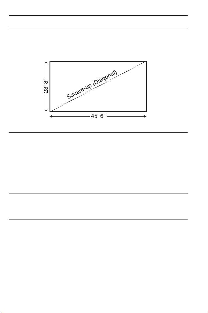
82 — S
HEET METAL/HVAC PRO CALC
CONCRETE/PAVING
Squaring-up a Foundation
A concrete foundation measures 23 Feet 8 Inches by 45 Feet 6
Inches. Find the diagonal measurement (Square-up) to ensure the
form is perfectly square.
KEYSTROKE DISPLAY
1. Enter sides as Rise/Run:
o o 0.
2 3 f 8 i r (Rise) Y 23 FEET 8 INCH
4 5 f 6 i R (Run) X 45 FEET 6 INCH
2. Find the Square-up (Diagonal):
d R 51 FEET 3-7/16 INCH
Volume of a Rectangle
Find the Volume of a Rectangle with the following dimensions: 36
Feet 3 Inches long, by 11 Feet 6 Inches wide, by 4 Inches deep.
KEYSTROKE DISPLAY
1. Multiply Length by Width:
o o 0.
3 6 f 3 i 36 FEET 3 INCH
x 1 1 f 6 i 11 FEET 6 INCH
2. Find Area:
= 416.875 SQ FEET
3. Multiply by Depth to find Volume:
x 4 i = 138.9583 CU FEET
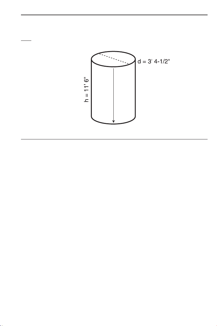
USER’S GUIDE — 83
Volume of Columns
Find the Volume of five (5) Columns, if each has a Diameter of 3
Feet 4-1/2 Inches and a Height of 11 Feet 6 Inches.
Note: Use the Column/Cone function ( Ç ) ).
KEYSTROKE DISPLAY
1. Find Circle Area:
o o 0.
3 f 4 i 1 / 2 3 FEET 4-1/2 INCH
C C C AREA 8.946176 SQ FEET
2. Enter Height and find the total Volume for five Columns:
1 1 f 6 i r (Rise) Y 11 FEET 6 INCH
Ç ) COL 102.881 CU FEET
x 5 = 514.4051 CU FEET
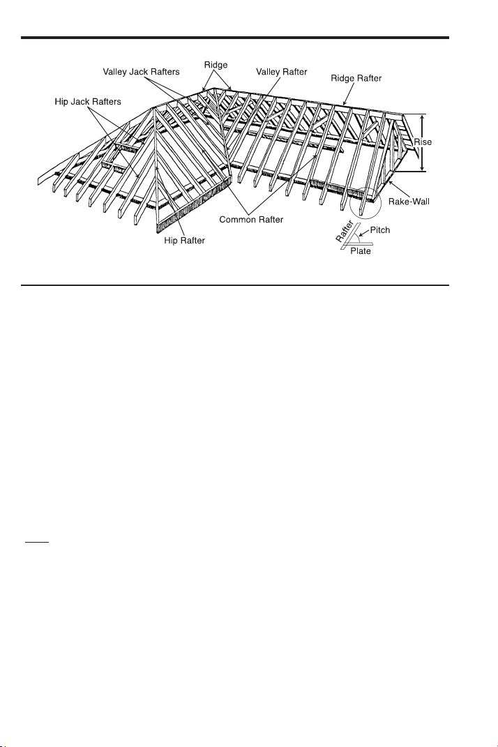
RIGHT TRIANGLE and ROOF FRAMING EXAMPLES
Roof Framing Definitions
y (Rise): The vertical distance measured from the wall’s top plate to
the intersection of the pitch line and the center of the ridge.
Span: The horizontal distance or full width between the outside
edges of the wall’s top plates.
x (Run): The horizontal distance between the outside edge of the
wall’s top plate and the center of the ridge; in most cases this is
equivalent to half of the span.
θ (Pitch): Pitch and Slope are synonymous in modern trade lan-
guage. Pitch/Slope of a roof is generally expressed in two types of
measurement:
1) Ratio of unit Rise to unit Run* — 7/12 or 7 Inch
2) Angle of rafters, in degrees — 30.26°
*Note: The unit rise is the number of Inches of Rise
per Foot (12 Inches) of unit Run.
The unit Run is expressed as one Foot (12 Inches).
Plate: The top horizontal wall member that the ceiling joist and
rafters sit on and fasten to.
Ridge: The uppermost point of two roof planes. This rafter is the
uppermost rafter that all Hip, Valley, Valley Jack, and Common
rafters are fastened to.
84 — SHEET METAL/HVAC PRO CALC
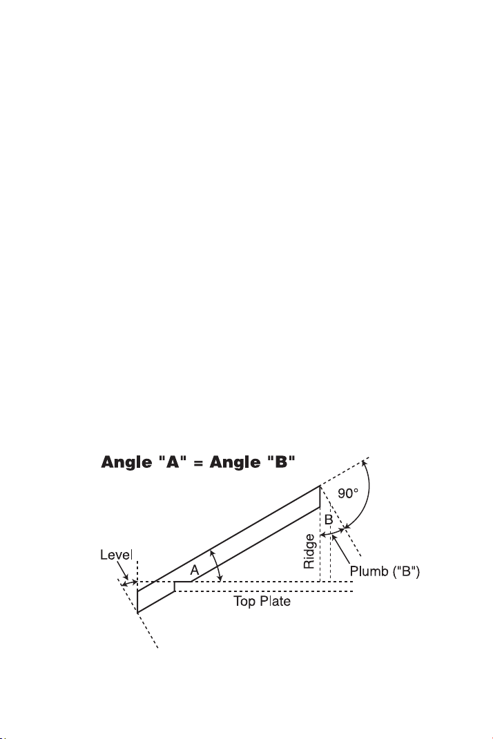
USER’S GUIDE — 85
Rafters: Rafters are inclined roof support members. Rafters include
the following types:
• Common Rafter: The Common connects the plate to the ridge
and is perpendicular to the ridge.
• Hip Rafter: The Hip rafter extends from the corner of two wall
plates to the ridge or King rafter at angle other than 90°. The Hip
rafter is an external angle of two planes.
• Valley Rafter: The Valley rafter extends from the corner of two
wall plates to the ridge or King rafter at angle other than 90°.
The Valley rafter is an internal angle of two planes.
• Jack Rafters: Rafters that connect the Hip or Valley rafter to the
wall plate.
• Irregular Hip/Valley Jacks: Jack rafters found in Dual-Pitch or
“Irregular” roofs.
Regular Roof: A standard roof where the Hips and/or Valleys run at
45° and have the same Pitch/Slope on both sides of the Hip and/or
Valley.
Irregular Roof: A non-standard roof where the Hips and/or Valleys
bisect two different Pitches/Slopes, or have “skewed wings” or
Irregular Jacks.
Rake-Wall: A gable end wall that follows the Pitch/Slope of a roof.

86 — S
HEET METAL/HVAC PRO CALC
Plumb: Vertical Cut. The angle of cut from the edge of the board
that allows the rafter to mate on the vertical side of the ridge rafter.
Level: Horizontal Cut. The angle of cut from the edge of the board
that allows the rafter to seat flat on the wall plate.
Cheek: Side Cut(s). The angle to cut from the SIDE of the Jack
rafter to match up against the Hip or Valley rafter, usually made by
tilting the blade from 90°. Jack rafters typically have one Cheek cut.
If there is only one Pitch (no Irregular Pitch), the angle will be 45°. If
there are two Pitches, each side will have a different Cheek cut for
the Jack rafter and the angles will total 90°.
Degree of Pitch
If the Degree of Pitch is 30.45°, what is the Percent Grade, Slope
and Pitch in Inches?
KEYSTROKE DISPLAY
o o 0.
3 0 • 4 5 p /
_
Ø 30.45°
p %GRD 58.78702
p SLP 0.58787
p PTCH 7-1/16 INCH
Note: To convert Pitch in Inches: Simply enter the Pitch in Inches first (e.g., 7 i
p), then continuously press the p key to calculate the Pitch conversions, as above.
Percent Grade
If the Percent Grade is 47.25%, what is the Slope, Pitch in Inches,
and Degree of Pitch?
KEYSTROKE DISPLAY
o o 0.
4 7 • 2 5 Ç +* p %GRD 47.25
p SLP 0.4725
p PTCH 5-11/16 INCH
p /
_
Ø 25.29073°
*Note: For entering Percent Grade, you need to label the value with the Percent key.

USER’S GUIDE — 87
Common Rafter Length
If a roof has a 7/12 Pitch and a Span of 14 Feet 4 Inches, what is
the Point-to-Point length of the Common rafter (excluding the over-
hang or ridge adjustment)? What are the Plumb and Level cuts?
KEYSTROKE DISPLAY
1. Find Diagonal or Point-to-Point length of the Common rafter:
o o 0.
7 i p PTCH 7 INCH
1 4 f 4 i ÷ 2 = 7 FEET 2 INCH
R X 7 FEET 2 INCH
d R 8 FEET 3-9/16 INCH
2. Find Plumb and Level cuts:
d PLMB 30.25644°
d LEVL 59.74356°
Common Rafter Length — Pitch Unknown
Find the Common rafter length for a roof with a Rise of 6 Feet 11-1/2
Inches and a Run of 14 Feet 6 Inches. Solve for the Pitch in
Degrees and in Inches.
KEYSTROKE DISPLAY
Find Diagonal and Pitch:
o o 0.
6 f 1 1 i 1 / 2 r Y 6 FEET 11-1/2 INCH
1 4 f 6 i R X 14 FEET 6 INCH
d R 16 FEET 1 INCH
p PTCH 5-3/4 INCH
p /
_
Ø 25.63565°

88 — S
HEET METAL/HVAC PRO CALC
Angle and Diagonal (Hypotenuse)
Find the Diagonal (Hypotenuse) and Degree of Angle of a Right
Triangle that is 9 Feet high and 12 Feet long.
KEYSTROKE DISPLAY
1. Enter Rise and Run:
o o 0.
9 f r Y 9 FEET 0 INCH
1 2 f R X 12 FEET 0 INCH
2. Solve for Diagonal/Hypotenuse, Pitch in Inches and Degree of
Angle:
d R 15 FEET 0 INCH
p PTCH 9 INCH
p /
_
Ø 36.8699°
Rise
Find the Rise given a 7/12 Pitch and a Run of 11 Feet 6 Inches.
KEYSTROKE DISPLAY
o o 0.
7 i p PTCH 7 INCH
1 1 f 6 i R X 11 FEET 6 INCH
r Y 6 FEET 8-1/2 INCH
Rise and Diagonal
Find the Rise and Diagonal of a Right Triangle given a 30° Pitch and
a Run of 20 Feet 4 Inches.
KEYSTROKE DISPLAY
o o 0.
3 0 p /
_
Ø 30.°
2 0 f 4 i R X 20 FEET 4 INCH
r Y 11 FEET 8-7/8 INCH
d R 23 FEET 5-3/4 INCH

USER’S GUIDE — 89
Sheathing Cut
You have framed an equal Pitch roof and need to apply the roof
sheathing. Find the distance from the corner of the sheathing so that
you can finish the Run at the Hip rafter and cut the material. The
Pitch is 6 Inches and you are using 4-Foot by 8-Foot plywood, with
the 8-Foot side along the plate.
KEYSTROKE DISPLAY
1. Enter Pitch:
o o 0.
6 i p PTCH 6 INCH
2. Enter width of plywood:
4 f d R 4 FEET 0 INCH
3. Find length of sheathing:
R X 3 FEET 6-15/16 INCH
Regular Hip/Valley and Jack Rafters
You’re working with a 7/12 Pitch, and half your total Span is 8 Feet 5
Inches:
(1) Find Point-to-Point length and cut angles for the Common rafter;
(2) Find the length and cut angles of the adjoining Hip (or Valley)
and;
(3) Find the Regular Jack rafter lengths and cut angles (Jack
rafters at 16 Inches On-Center spacing).
KEYSTROKE DISPLAY
1. Find Common rafter length and Plumb and Level cuts:
o o 0.
8 f 5 i R X 8 FEET 5 INCH
7 i p PTCH 7 INCH
d R 9 FEET 8-15/16 INCH
d PLMB 30.25644°
d LEVL 59.74356°
(Cont’d)

90 — S
HEET METAL/HVAC PRO CALC
(Cont’d)
KEYSTROKE DISPLAY
2. Find Hip/Valley rafter length and cut angles:
H H/V 12 FEET 10-1/2 INCH
H PLMB 22.41512°
H LEVL 67.58488°
H CHK1 45.°
3. Find Jack rafter lengths and cut angles:
j JKOC 16 INCH*
j JK1 8 FEET 2-3/8 INCH
j JK2 6 FEET 7-7/8 INCH
j JK3 5 FEET 1-3/8 INCH
j JK4 3 FEET 6-13/16 INCH
j JK5 2 FEET 0-5/16 INCH
j JK6 0 FEET 5-13/16 INCH
j JK7 0 FEET 0 INCH
j PLMB 30.25644°
j LEVL 59.74356°
j CHK1 45.°
*Note: If display does not read JKOC 16 INCH (the default), then enter 16 Inches
prior to beginning calculation (e.g., 1 6 i j).

USER’S GUIDE — 91
Jack Rafters — Using Other Than 16 Inch On-Center Spacing
A roof has a 9/12 Pitch and a Run of 6 Feet 9 Inches. Find the Jack
rafter lengths and cut angles at 18-Inch (versus 16-Inch) On-Center
spacing. The On-Center spacing is used for both Regular and
Irregular Jack calculations.
KEYSTROKE DISPLAY
1. Enter Pitch, Run, and On-Center spacing:
o o 0.
9 i p PTCH 9 INCH
6 f 9 i R X 6 FEET 9 INCH
1 8 i j j JKOC 18 INCH
2. Find Jack rafter lengths and cut angles:
j JK1 6 FEET 6-3/4 INCH
j JK2 4 FEET 8-1/4 INCH
j JK3 2 FEET 9-3/4 INCH
j JK4 0 FEET 11-1/4 INCH
j JK5 0 FEET 0 INCH
j PLMB 36.8699°
j LEVL 53.1301°
j CHK1 45.°
3. Reset On-Center spacing to 16 Inches:
1 6 i j JKOC 16
INCH
STORED

92 — S
HEET METAL/HVAC PRO CALC
Irregular Hip/Valley and Jack Rafters — Descending, with
On-Center Spacing Maintained
You’re working with a 7/12 Pitch and half your overall Span is 4
Feet. The Irregular Pitch is 8/12, and 16-Inch On-Center spacing is
maintained on both sides. Complete the following steps:
(1) Find the length of the Common rafter;
(2) Reset calculator to 16-Inch On-Center spacing;
(3) Enter the Irregular Pitch; find the length of the adjoining
“Irregular” Hip (or Valley) and the cut angles;
(4) Find the Jack lengths on the “Irregular” Pitch side (16-Inch
On-Center spacing);
(5) Find the cut angles;
(6) Find the Jack lengths on the “Regular” Pitch side (16-Inch
On-Center spacing);
(7) Find the cut angles.
KEYSTROKE DISPLAY
1. Find Common rafter length:
o o 0.
7 i p PTCH 7 INCH
4 f R X 4 FEET 0 INCH
d R 4 FEET 7-9/16 INCH
2. Enter On-Center spacing:
1 6 i j JKOC 16 INCH
3. Find Irregular Hip/Valley rafter length and cut angles:
8 i Ç H IPCH 8 INCH
H IH/V 5 FEET 9-11/16 INCH
H PLMB 23.70162°
H LEVL 66.29838°
H CHK1 41.18592°
H CHK2 48.81408°
4. Find Irregular Jack lengths:
Ç j IJOC 16
INCH
j* IJ1 2 FEET 9-5/8 INCH
j IJ2 1 FEET 4-13/16 INCH
j IJ3 0 FEET 0 INCH
*Note: It is not necessary to continue pressing Ç when displaying each Jack rafter
size.
(Cont’d)
STORED

USER’S GUIDE — 93
(Cont’d)
KEYSTROKE DISPLAY
5. Find Irregular Jack Plumb, Level, and Cheek cut angles:
j PLMB 33.69007°
j LEVL 56.30993°
j CHK1 41.18592°
6. Find Regular Jack lengths:
j JKOC 16 INCH
j JK1 2 FEET 10-3/8 INCH
j JK2 1 FEET 1-1/4 INCH
j JK3 0 FEET 0 INCH
7. Find Regular Jack Plumb, Level, and Cheek cut angles:
j PLMB 30.25644°
j LEVL 59.74356°
j CHK1 48.81408°
STORED

STAIR LAYOUT EXAMPLES
Stair Layout Definitions
y (Rise): The “floor-to-floor” or “landing-to-landing” Rise is the actual
vertical Rise required for building a stairway after the finish flooring
has been installed.
x (Run): The Run of a
stairway is the amount of horizontal space
required. The total Run of a stairway is equal to the width of each
Tread multiplied by the number of Treads.
Desired Riser Height: The desired Riser height is the amount of
vertical Rise you allow for each individual Riser in the stairway. This
is sometimes dictated by local code.
Actual Riser Height: The actual height of each Riser is measured
from the top of one Tread to the top of the next Tread.
94 — SHEET METAL/HVAC PRO CALC

USER’S GUIDE — 95
Number of Risers: The number of Risers includes both the first and
the last Riser of the stairway.
Riser Overage or Underage: The Riser Overage or Underage is
the difference between the “floor-to-floor” Rise and the total height of
all of the Risers. Many times the Riser height does not divide evenly
into the floor-to-floor Rise and a small fraction of an Inch is left over.
A positive remainder is an Overage, while a negative remainder is
an Underage.
Tread Width: The width of each Tread is measured from the front of
one Riser to the front of the next Riser. The width of each Tread
does NOT include the nosing or overhang of the Tread. The nosing
or overhang of a Tread is the rounded front of the Tread that proj-
ects beyond the face of the Riser.
Number of Treads: The number of Treads is one less than the
number of Risers.
Tread Overage or Underage: The Tread Overage or Underage is
the difference between the Run or horizontal space that a stairway
must fit into and the total width of the Treads. Similar to the Riser
Overage/Underage, many times the total width of the Treads does
not divide evenly into the Run or horizontal space for the stairway
and a small fraction of an Inch is left over. A positive remainder is an
Overage, a negative remainder is an Underage.
Stringer: Also called a Carriage, Stair Horse, or Stair Jack. A Stringer
is the diagonal member that supports the Treads and Risers.
Angle of Incline: The angle of incline of the stairway is determined
by the Rise and Run of each stair. The angle of incline should not be
confused with the Pitch of the stairway. The Pitch of a stairway is the
angle based on the floor-to-floor Rise and the horizontal Run of the
stairway. The angle of incline is based on the “actual” Riser height
and the “actual” Tread width of the stair.
Stairwell Opening: The length of the opening at the top of the
stairs. The computation is based on the Headroom Height (the
desired spacing between the stairs and upper floor ceiling) and
thickness of the upper floor where the opening is located.

96 — S
HEET METAL/HVAC PRO CALC
Stairs — Given Only Floor-to-Floor Rise
You’re building a stairway with a total Rise of 9 Feet 11 Inches. Your
desired Riser height is 7-1/2 Inches and desired Tread width is 10
Inches. The desired Headroom is 6 Feet 8 Inches and Floor
Thickness 10 Inches*. Find all stair values, then calculate the Run.
*Note: Headroom and Floor Thickness are required to calculate the height of the stair-
well opening.
KEYSTROKE DISPLAY
1. Enter known Rise:
o o 0.
9 f 1 1 i r Y 9 FEET 11 INCH
2. Recall (default) stored “desired” stair Riser height:
® s R-HT 7-1/2 INCH
3. Find Riser height, number of Risers, Riser Overage/Underage,
Tread width, number of Treads, Tread Overage/Underage, length of
stairwell opening, Stringer length and Angle of Incline. As a final
step, calculate the Run:
s R-HT 7-7/16 INCH
s RSRS 16.
s R+/– 0 INCH
s T-WD 10 INCH
s TRDS 15.
s T+/– 0 INCH
s OPEN 10 FEET 1 INCH
s STRG 15 FEET 6-15/16 INCH
s INCL 36.64003°
s RUN 12 FEET 6 INCH
s* RISE (Y) 9 FEET 11 INCH
*Continuous presses of s will also recall stored desired Riser height, Tread,
Headroom and Floor Thickness values.
STORED
STORED

USER’S GUIDE — 97
To Change Desired Riser Height: If you wish to use a desired
Riser height of other than 7-1/2 Inches (the calculator’s default), sim-
ply enter a new value. For example, to enter eight Inches, enter 8
i Ç s. Press ® s to review your new entry. This
value will be permanently stored until you change it.
To Change Desired Tread Width: If you wish to use a desired
Tread width of other than ten Inches (the calculator’s default), simply
select a new value via the Preference Mode (press Ç, then =
four times and use the + or – keys to increase/decrease by 1/4
Inch increments). This value will be permanently stored until you
change it.
To Change Desired Headroom: If you wish to use a desired
Headroom other than six Feet eight Inches (the calculator’s default),
simply select a new value via the Preference Mode (press Ç,
then = five times and use the + or – keys to increase/decrease
by one-Inch increments). See below example. This value will be per-
manently stored until you change it.
To Change Desired Floor Thickness: If you wish to use a desired
Floor Thickness of other than ten Inches (the calculator’s default),
simply select a new value via the Preference Mode (press Ç,
then = six times and use the + or – keys to increase/decrease by
one-Inch increments). This value will be permanently stored until you
change it.
KEYSTROKE DISPLAY
1. Select Headroom via Preference Mode:
o o 0.
Ç = = = = = HDRM 6 FEET 8 INCH
2. Decrease Headroom Height by two Inches:
– – HDRM 6 FEET 6 INCH
3. Then increase Headroom Height by four Inches:
+ + + + HDRM 6 FEET 10 INCH
4. Return Headroom Height to default of six Feet eight Inches:
– – HDRM 6 FEET 8 INCH

98 — S
HEET METAL/HVAC PRO CALC
Stairs — Given Only the Run
You’re building a stairway with a total Run of 20 Feet. Your desired
Riser height is 7-1/2 Inches and desired Tread width is ten Inches
(default, or preset values). The desired headroom is 6 Feet 8 Inches
and floor thickness 10 Inches (defaults). Find all stair values, then
calculate the Rise.
KEYSTROKE DISPLAY
1. Enter Run:
o o 0.
2 0 f R X 20 FEET 0 INCH
2. Find Riser height, number of Risers, Riser Overage/Underage,
Tread width, number of Treads, Tread Overage/Underage, stairwell
opening, Stringer length and Angle of Incline. As a final step, calcu-
late the Rise:
s R-HT 7-1/2 INCH
s RSRS 25.
s R+/– 0 INCH
s T-WD 10 INCH
s TRDS 24.
s T+/– 0 INCH
s OPEN 10 FEET 0 INCH
s STRG 25 FEET 0 INCH
s INCL 36.8699°
s RUN (X) 20 FEET 0 INCH
s RISE 15 FEET 7-1/2 INCH
STORED

USER’S GUIDE — 99
Stairs — Given Rise and Run
You need to build a stairway with a floor-to-floor height of 10 Feet 1
Inch, a Run of 15 Feet 5 Inches, and a nominal desired Riser height
of 7-1/2 Inches (default). Calculate all stair values.
KEYSTROKE DISPLAY
1. Enter Rise and Run:
o o 0.
1 0 f 1 i r Y 10 FEET 1 INCH
1 5 f 5 i R X 15 FEET 5 INCH
2. Find stair values:
s R-HT 7-9/16 INCH*
s RSRS 16.
s R+/– 0 INCH
s T-WD 12-5/16 INCH
s TRDS 15.
s T+/– – 0-5/16 INCH
s OPEN 12 FEET 2-1/2 INCH
s STRG 18 FEET 0-3/4 INCH
s INCL 31.5588°
s RUN (X) 15 FEET 5 INCH
s RISE (Y) 10 FEET 1 INCH
s R-HT 7-1/2 INCH
s T-WD 10 INCH
s HDRM 6 FEET 8 INCH
s FLOR 10 INCH
*A yield symbol (
)
will light in the display meaning the calculated Riser height
exceeds the stored desired Riser height by 10%.
STORED
STORED
STORED
STORED
STORED
STORED

100 — SHEET METAL
/HVAC PRO CALC
Baluster Spacing
You are going to install a handrail at the top of a balcony. Your total
Span is 156 Inches and you would like the space between the balus-
ters to be about 4 Inches. If each baluster is 1-1/2 Inches wide, what
is the exact spacing between each baluster?
KEYSTROKE DISPLAY
1. Estimate number of balusters in Span:
o o 0.
1 5 6 i ÷ 156 INCH
5 i 1 / 2 =* 28.36364 (28 balusters)
*desired spacing plus baluster width (4 Inches plus 1-1/2 Inches).
2. Find total space ‘occupied’ by the balusters by multiplying the
width of each baluster by the rounded number of balusters (found
above):
1 i 1 / 2 x 1-1/2 INCH
2 8 = 42 INCH
3. Find total space between all balusters:
1 5 6 i – 156 INCH
4 2 i = 114 INCH
4. Find actual baluster spacing by dividing total space between all
balusters by the number of spaces between the balusters (number
of balusters plus one equals 29):
1 1 4 i ÷ 114 INCH
2 9 = 3-15/16 INCH

USER’S GUIDE — 101
The Sine of an angle is the ratio of the opposite side over the
Hypotenuse:
The Cosine of an angle is the ratio of the adjacent side over the
Hypotenuse:
The Tangent of an angle is the ratio of the opposite side over the
adjacent side:
Tangent Tan =
Opposite
Adjacent
tan A =
a
b
c
a
b
A
Cosine Cos =
Adjacent
Hypotenuse
cos A =
b
c
c
a
b
A
Sine Sin =
Opposite
Hypotenuse
sin A =
a
c
c
a
b
A
APPENDIX A — TRIGONOMETRY FORMULAS
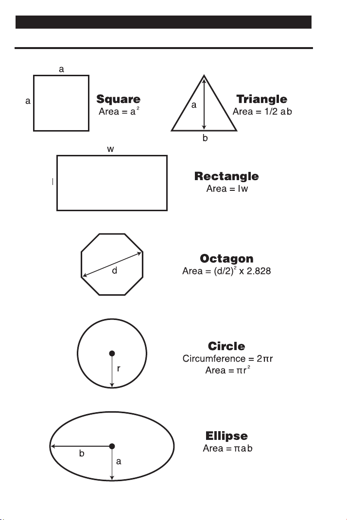
102 — SHEET METAL
/HVAC PRO CALC
AREA FORMULAS
APPENDIX B — AREA / VOLUME FORMULAS
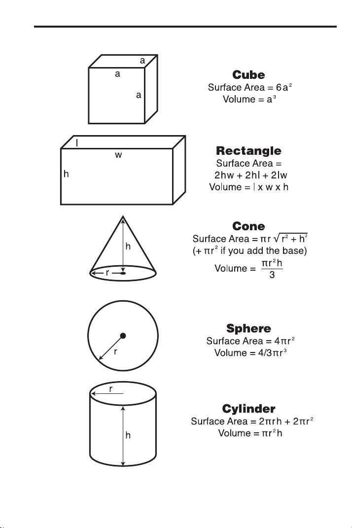
USER’S GUIDE — 103
SURFACE AREA / VOLUME FORMULAS

104 — SHEET METAL
/HVAC PRO CALC
With Offset = “y” and Length = “x,”
WrapperLength (aka StretchOut) = CenterlineRadius * ArcK * 4θ
HeelRadius = CenterlineRadius + (a ÷ 2)
ThroatRadius = CenterlineRadius – (a ÷ 2)
CenterlineRadius = =
SlantLength
4Sin(θ)
SlantLength
2
4 * Offset
θ = ArcSin = ArcTan
Offset
SlantLength
()
= ArcTan
Offset
Length
()
y
x
()
APPENDIX C — OFFSET FORMULAS
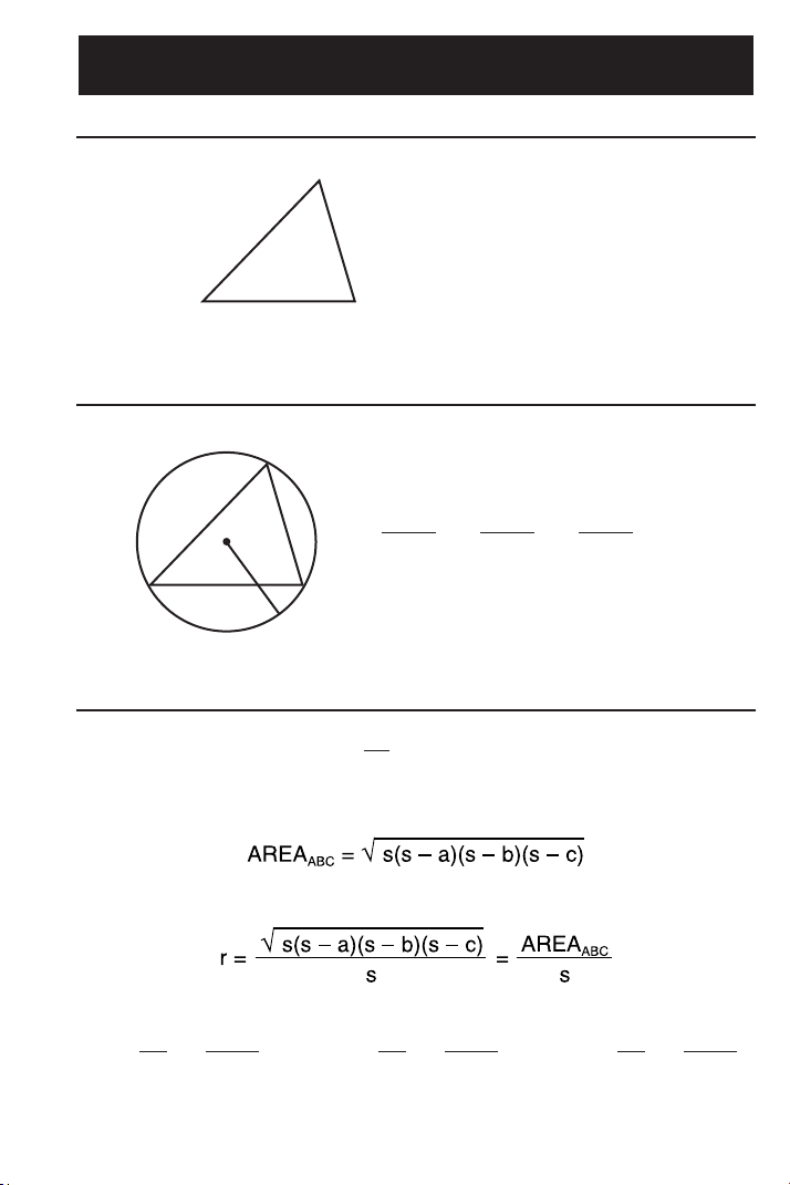
USER’S GUIDE — 105
Law of Cosines
Law of Sines
Heron’s Theorem
Tan =
A
2
r
s – a
()
Tan =
B
2
r
s – b
()
Tan =
C
2
r
s – c
()
s = (a + b + c)
1
2
A
CaB
c
b
a
=
b
=
c
= 2R
sin A sin B sin C
R
A
BaC
b
c
a
2
= b
2
+ c
2
– 2bccosA
b
2
= c
2
+ a
2
– 2cacosB
c
2
= a
2
+ b
2
– 2abcosC
APPENDIX D — LAW OF COSINES / HERON’S
THEOREM FORMULAS
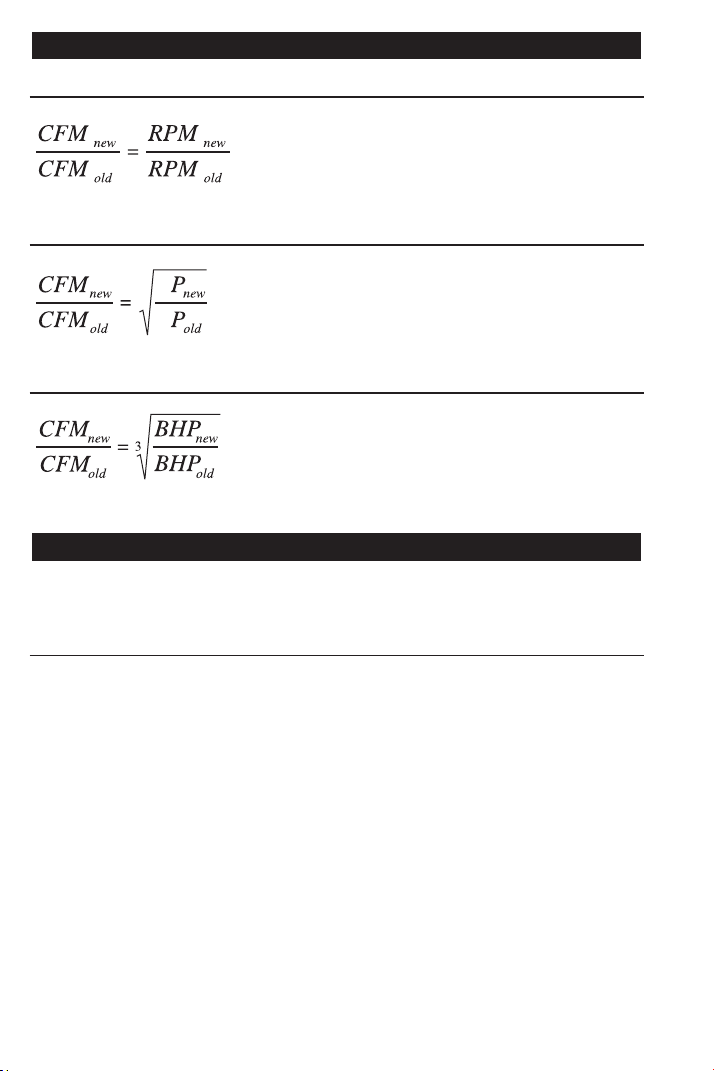
Fan Law 1 Formula
Fan Law 2 Formula
Fan Law 3 Formula
After a Full Reset/Clear All, your calculator will return to the following
settings:
SETTING IMPERIAL
16 Inches
1/16
Standard
Standard
7-1/2 Inches
10 inches
6 Feet 8 Inches
10 Inches
Descending
OC-OC
On
0.000
Float
On-Center Spacing
Fractional Resolution
Area Display
Volume Display
Desired Riser Height
Desired Tread Width
Stairway Headroom
Floor Thickness (Stairs)
Jack Rafters
Irregular Jack Spacing
Exponent
Meter Linear Rounding
Degree Rounding
Mathematical Operations
106 — SHEET METAL
/HVAC PRO CALC
Order of Operations Method
APPENDIX F — DEFAULT SETTINGS
where,
BHP = Brake Horsepower
CFM = Feet
3
per Minute
S
S
where,
SP = Static Pressure
CFM = Feet
3
per Minute
where,
CFM = Feet
3
per Minute
RPM = Revolutions per Minute
APPENDIX E — FAN LAW FORMULAS

USER’S GUIDE — 107
Your calculator has Preference Settings that allow you to customize
or set desired dimensional formats and calculations. See the list of
Settings below and instructions how to set them on the following
page.
If you replace your batteries or perform a Full Reset* (press O, hold
down x, and press o), your calculator will return to the following
settings (in addition to those listed on the previous page):
PREFERENCE OPTIONS
1) Fractional Resolution — *1/16 (displays fractional values to
the nearest 16th of an Inch)
— 1/32
— 1/64
— 1/2
— 1/4
— 1/8
2) Area Display Format — *Standard (if units entered are the
same — e.g., Feet x Feet — the answer
will remain in this format (Square Feet),
but if units entered are different — e.g.,
Inches x Feet — area answer will be
displayed in Square Feet)
— Square Feet (area answers always
displayed in Square Feet, regardless of
unit entry — e.g., Inches x Inches =
Square Feet)
— Square Meters (area answers
always displayed in Square meters —
e.g., Feet x Feet = Square Meters)
(Cont’d)
APPENDIX G — PREFERENCE SETTINGS

108 — SHEET METAL
/HVAC PRO CALC
(Cont’d)
PREFERENCE OPTIONS
3) Volume Display Format — *Standard (if units entered are the
same — e.g., Feet x Feet x Feet — the
answer will remain in this format (Cubic
Feet), but if units entered are different
— e.g., Feet x Feet x Inches — volume
answer will always be displayed in
Cubic Feet)
— Cubic Feet (volume answers always
displayed in Cubic Feet, regardless of
unit entry — e.g., Inches x Inches x
Inches = Cubic Feet)
— Cubic Meters (volume answers
always displayed in Cubic Meters,
regardless of unit entry — e.g., Feet x
Feet x Feet = Cubic Meters)
4) Tread Width — *10 Inch (default)
— Use + or – key to increase or
decrease above value by increments of
1/4 Inch
5) Stairwell — Headroom — *6 Feet 8 Inch (default)
Height — Use + or – key to increase or
decrease above value by increments of
1 Inch
6) Floor Thickness — *10 Inch (default)
— Use + or – key to increase or
decrease above value by increments of
1 Inch
7) Jack Rafters — *Descending (Jack rafters are
Descending or Ascending displayed from largest to smallest size)
— Ascending (Jack rafters are
displayed from smallest to largest size)
(Cont’d)

USER’S GUIDE — 109
(Cont’d)
PREFERENCE OPTIONS
8) Irregular Jack Rafters — *OC-OC (On-Center spacing
O-C or Mate maintained on both Regular and
Irregular sides)
— JAC-JAC (Regular/Irregular Jack
rafters “mate” at the Hip/Valley, i.e., On-
Center spacing not maintained on both
sides)
9) Exponent Off or On — *On (Exponential Mode is On; turns
on Auto-Ranging; i.e., if display can’t
show seven digits, will display in next
largest unit)
— Off (Exponential Mode is Off)
10) Meter Linear Display — *0.000 (Linear Meter answers always
11) Degrees Displayed
12) Mathematical
Operations
13) Fractional Mode
displayed to third
decimal place)
— FLOAT (Linear Meter answers dis-
played to the maximum number of deci-
mal points, as entered — e.g., 1.234
Meters + 2.56 Meters = 3.794 Meters)
— *FLOAT
— 0.00°
— *Order (Order of Operations Method
of Calculating)
— Chain (Chain Method)
— *Standard (fractions are displayed to
the nearest fraction)
— Constant (fractions are displayed in
the set fractional resolution)

110 — SHEET METAL
/HVAC PRO CALC
How to Set Preferences
The following sections detail Preference Setting options.
Enter the Preference Mode by pressing Ç = (Prefs). Access
each category by pressing the = key until you reach the desired
setting. Within each category, press the + or – keys to toggle
between individual selections. Press o to exit and set in your
Preference.
Note: + will advance, – will back up. Pressing the = key continuously in this mode
will revolve the Preference Settings full circle.
You may change these settings at any time by repeating the above,
and setting in a new preference. Or, you may review settings by
pressing ® =.
For example, if you wish to display all your dimensional area
answers in Square Meters, press Ç = = (Area Std), then the +
key until “AREA 0. SQ M” is displayed. Simply exit this mode by
pressing o or any key, and all your future area answers will be
displayed in Square Meters.

USER’S GUIDE — 111
Accessing Preference Settings
To Set “Fractional Resolution”:
KEYSTROKE DISPLAY
Ç = (Prefs) (first press of =) FRAC 0-1/16 INCH
+ (plus sign) FRAC 0-1/32 INCH
+ FRAC 0-1/64 INCH
+ FRAC 0-1/2 INCH
+ FRAC 0-1/4 INCH
+ FRAC 0-1/8 INCH
To Set “Area” Answer Format:
KEYSTROKE DISPLAY
= (second press of =) AREA Std.
+ (plus sign) AREA 0. SQ FEET
+ AREA 0. SQ M
To Set “Volume” Answer Format:
KEYSTROKE DISPLAY
= (third press of =) VOL Std.
+ (plus sign) VOL 0. CU FEET
+ VOL 0. CU M
To Increase or Decrease Tread Width from Default of 10”:
KEYSTROKE DISPLAY
= (fourth press of =) T-WD 10 INCH
+* (plus sign increases height by 1/4 Inch) T-WD 10-1/4 INCH
–* (minus sign decreases height by 1/4 Inch) T-WD 10 INCH
*Keep pressing plus or minus to increase or decrease 1/4 Inch at a time.
To Increase or Decrease Stairwell “Headroom” from Default of 6’8”:
KEYSTROKE DISPLAY
= (fifth press of =) HDRM 6 FEET 8 INCH
+* (plus sign increases height by 1 Inch) HDRM 6 FEET 9 INCH
–* (minus sign decreases height by 1 Inch) HDRM 6 FEET 8 INCH
*Keep pressing plus or minus to increase or decrease an Inch at a time.
(Cont’d)

112 — SHEET METAL
/HVAC PRO CALC
(Cont’d)
To Increase or Decrease Floor Thickness from Default of 10”:
KEYSTROKE DISPLAY
= (sixth press of =) FLOR 10 INCH
+* (plus sign increases height by 1 Inch) FLOR 11 INCH
–* (minus sign decreases height by 1 Inch) FLOR 10 INCH
*Keep pressing plus or minus to increase or decrease an Inch at a time.
To Set Jack Rafter to “Descending” or “Ascending”:
KEYSTROKE DISPLAY
= (seventh press of =) JACK dESCEnd
+ (plus sign) JACK ASCEnd
To Set Irregular Jack Spacing to “On-Center” or “Mate”:
KEYSTROKE DISPLAY
= (eighth press of =) IRJK OC-OC
+ (plus sign) IRJK JAC-JAC
To Set “Exponential Mode” On or Off:
KEYSTROKE DISPLAY
= (ninth press of =) EXP On
+ (plus sign) EXP OFF
To Set “Meter” Linear Decimal Format:
KEYSTROKE DISPLAY
= (tenth press of =) METR 0.000 M
+ (plus sign) METR FLOAt M
To Set “Degrees” Rounding/Display:
KEYSTROKE DISPLAY
= (eleventh press of =) DEG FLOAt
+ (plus sign) DEG 0.00°
(Cont’d)

USER’S GUIDE — 113
(Cont’d)
To Set Mathematical Operations Method:
KEYSTROKE DISPLAY
= (twelfth press of =) MATH OrdEr
+ (plus sign) MATH CHAIn
To Set Fractional Mode:
KEYSTROKE DISPLAY
= (thirteenth press of =) FRAC Std.
+ (plus sign) FRAC COnSt
+ (repeats options) FRAC Std.
Note: Press o at any time to exit the Preference Mode. To Reset your calculator to
the default Preference Settings, turn off your calculator, hold down the multiplication
x key, and turn on. “ALL rESEt” will flash for one second before clearing the display.
Please follow the guidelines listed in this section for proper care and
operation of your calculator. Not following the instructions listed
below may result in damage not covered by your warranty. Refer to
the Repair and Return section on page 116 for more details.
Do not expose calculator to temperatures outside the operating
temperature range of 32ºF – 104ºF (0ºC – 40ºC).
Do not expose calculator to high moisture such as submersion
in water, heavy rain, etc.
APPENDIX H — CARE INSTRUCTIONS

Accuracy/Errors
Accuracy/Display Capacity — Your calculator has a twelve-digit
display made up of eight digits (normal display) and four fractional
digits. You may enter or calculate values up to 19,999,999.99. Each
calculation is carried out internally to ten digits.
Errors — When an incorrect entry is made, or the answer is beyond
the range of the calculator, it will display the word “ERROR.” To clear
an error condition you must hit the o button once. At this point
you must determine what caused the error and re-key the problem.
Error Codes:
Display Error Type
0-fL0 Overflow (too large to display)
EXP Error Exponent Error
DIV Error Divide by 0 Error
DIM Error Dimension error
ENT Error Entry error
TYP Error Type error
TRIG Error Trig. error (for example, tan of 1 foot)
None Attempt to calculate stairs without entering
rise or run
Auto-Range —
If
an “overflow” is created because of an input and
calculation with small units that are out of the standard range of the
display (e.g. 19,999,999.99), the answer will be automatically
expressed in the next larger units (instead of showing “ERROR”) —
e.g., 20,000,000 mm is shown as 20,000 m. Also applies to inches,
feet and yards.
Note: If Exponential Notation is activated through the Preference Setting, the value
will be shown in scientific notation (e.g., 100 million mm—1.000000
8
mm).
114 — SHEET METAL/HVAC PRO CALC
APPENDIX I — ACCURACY, AUTO SHUT-OFF,
BATTERIES, ERRORS

USER’S GUIDE — 115
Auto Shut-Off
Your calculator is designed to shut itself off after about 8-12 Minutes
of non-use.
Battery(ies)
• Two LR44 batteries.
Replacing the Battery(ies)
Should your calculator display become very dim or erratic, replace
the battery(ies).
Note: Please use caution when disposing of your old battery, as it contains hazardous
chemicals.
Replacement batteries are available at most discount or electronics
stores. You may also call Calculated Industries at 1-775-885-4975.
Battery Replacement Instructions
To replace the batteries, slide open the battery door (at top backside
of unit) and replace with new batteries. Make sure the batteries are
facing positive side up.
Reset Key
If your calculator should ever “lock up,” press Reset — a small hole
located to the left of the O key — to perform a total reset.

116 — SHEET METAL/HV
AC PRO CALC
WARRANTY, REPAIR AND RETURN INFORMATION
Return Guidelines
1. Please read the Warranty in this User's Guide to determine if
your Sheet Metal/HVAC Pro Calc calculator remains under
warranty before calling or returning any device for evaluation or
repairs.
2. If your calculator won't turn on, try pressing the Reset button
first. If it still won't turn on, check the batteries as outlined in the
User's Guide.
3. If there is a black spot on the LCD screen, THIS IS NOT A
WARRANTY DEFECT. The unit can be repaired. Call for a
repair quote before returning your unit.
4. If you need more assistance, please contact the dealer through
which you initially purchased the product.
REPAIR AND RETURN

USER’S GUIDE — 117
Warranty Repair Service – U.S.A.
Calculated Industries (“CI”) warrants this product against defects in
materi-
als and workmanship for a period of one (1) year from the date of original
consumer purchase in the U.S. If a defect exists during the warranty period,
CI at its option will either repair (using new or remanufactured parts) or
replace (with a new or remanufactured calculator) the product at no charge.
THE WARRANTY WILL NOT APPLY TO THE PRODUCT IF IT HAS BEEN
DAMAGED BY MISUSE, ALTERATION, ACCIDENT, IMPROPER HAN-
DLING OR OPERATION, OR IF UNAUTHORIZED REPAIRS ARE
ATTEMPTED OR MADE. SOME EXAMPLES OF DAMAGES NOT COV-
ERED BY WARRANTY INCLUDE, BUT ARE NOT LIMITED TO, BATTERY
LEAKAGE, BENDING, OR VISIBLE CRACKING OF THE LCD, WHICH ARE
PRESUMED TO BE DAMAGES RESULTING FROM MISUSE OR ABUSE.
To obtain warranty service in the U.S., please contact the dealer through
which you initially purchased the product.
A repaired or replacement product assumes the remaining warranty of the
original product or 90 days, whichever is longer.
Non-Warranty Repair Service – USA
Non-warranty repair covers service beyond the warranty period or service
requested due to damage resulting from misuse or abuse.
Contact Calculat
ed Industries at 1-775-885-4900, to obtain current product
repair information and charges. Repairs are guaranteed for 90 days.
Repair Service – Outside the USA
To obtain warranty or non-warranty repair service for goods purchased out-
side the U.S., contact the dealer through which you initially purchased the
product. If you cannot reasonably have the product repaired in your area,
you may contact CI to obtain current product repair information and charges,
including freight and duties.
Disclaimer
CI MAKES NO WARRANTY OR REPRESENTATION, EITHER EXPRESS
OR IMPLIED, WITH RESPECT TO THE PRODUCT’S QUALITY, PER-
FORMANCE, MERCHANTABILITY, OR FITNESS FOR A PARTICULAR
PURPOSE. AS A RESULT, THIS PRODUCT, INCLUDING BUT NOT LIMIT-
ED TO, KEYSTROKE PROCEDURES, MATHEMATICAL ACCURACY AND
PREPROGRAMMED MATERIAL, IS SOLD “AS IS,” AND YOU THE PUR-
CHASER ASSUME THE ENTIRE RISK AS TO ITS QUALITY AND PER-
FORMANCE.
IN NO EVENT WILL CI BE LIABLE FOR DIRECT, INDIRECT, SPECIAL,
WARRANTY

118 — SHEET METAL/HV
AC PRO CALC
INCIDENTAL, OR CONSEQUENTIAL DAMAGES RESULTING FROM ANY
DEFECT IN THE PRODUCT OR ITS DOCUMENTATION.
The warranty, disclaimer, and remedies set forth above are exclusive and
replace all others, oral or written, expressed or implied. No CI dealer, agent,
or employee is authorized to make any modification, extension, or addition
to this warranty.
Some states do not allow the exclusion or limitation of implied warranties or
liability for incidental or consequential damages, so the above limitation or
exclusion may not apply to you. This warranty gives you specific rights, and
you may also have other rights, which vary from state to state.
FCC Class B
This equipment has been certified to comply with the limits for a Class B
computing device, pursuant to Subpart J of Part 15 of FCC rules.
Legal Notes
User’s Guide copyrighted by Calculated Industries, Inc., 2021.
Calculated Industries
®
is a registered trademark of
Calculated Industries, Inc.
ALL RIGHTS RESERVED
Designed in the USA
Looking For New Ideas
Calculated Industries, a leading manufacturer of special-function calculators
and digital measuring instruments, is always looking for new product ideas
in these areas.
If you have an idea, or a suggestion for improving this product or User’s
Guide, please submit your comments online at: www.calculated.com under
“Contact Us,” “Product Idea.” Thank you.

USER’S GUIDE — 119
Accessing Preference Settings, 111
ACCURACY, AUTO SHUT-OFF, BATTERIES, ERRORS (APPENDIX I), 114
Accuracy/Errors, 114
Adding and Subtracting Fractions of an Inch, 35
Adding Dimensions, 29
Adding Linear Measurements, 34
Angle and Diagonal (Hypotenuse), 88
Arc Calculations — Arc Length and Diameter Known, 79
ARC/CIRCLE EXAMPLES, 78
Arched/Circular Rake-Walls — Chord Length and Segment Rise Known, 80
Arched Windows, 81
Arc Length — Degree and Diameter Known, 78
Arc Length — Degree and Radius Known, 78
AREA FORMULAS, 102
Area of a Rectangle, 36
Area of a Triangle, 37
AREA/VOLUME FORMULAS (APPENDIX B), 102
Auto Shut-Off, 115
Baluster Spacing, 100
BASIC EXAMPLES, 34
BASIC OPERATION KEYS, 6
Battery(ies), 115
Battery Replacement Instructions, 115
Calculating Angles Between Objects (“Angle Between”), 69
Calculating Angles Between Objects Example, 70
CARE INSTRUCTIONS (APPENDIX H), 113
Change OGEE Offset, 53
CIRCULAR/ARC FUNCTION KEYS, 15
Circumference and Area of a Circle, 36
Circumference of a Circle, 36
COLUMN/CONE KEY, 16
Common Rafter Length, 87
Common Rafter Length — Pitch Unknown, 87
CONCRETE/PAVING, 82
CONVERSIONS (LINEAR, AREA, VOLUME), 27
CONVERT Ç KEY—UNIT CONVERSIONS and SECOND FUNCTIONS, 6
Converting Decimal Feet to Feet-Inches-Fractions, 27
Converting Decimal Inches to Fractional Inches, 28
Converting Decimals to Fractions, 35
Converting degrees:minutes:seconds, 45
Converting Feet-Inches-Fractions to Decimal Feet, 27
Converting Feet-Inches to Meters and Millimeters, 34
Converting Feet-Inch-Fractions to Decimal Feet and Fractions of an Inch, 34
Converting FPM to Velocity Pressure, 47
Converting Fractional Inches to Decimal Inches, 27
Converting Fractions to Decimals, 35
Converting Pitch to Angle/Tangent, 45
Converting Velocity Pressure to FPM, 46
Cubed Function, 39
Cubed Root Function, 39
Cubic Conversions, 28
DEFAULT SETTINGS (APPENDIX F), 106
INDEX

Degree of Pitch, 86
Dividing Dimensions, 29
Dividing Offset into Multiple Degreed Elbows for Manageable Sections, 51
D:M:S EXAMPLE, 45
ENTERING DIMENSIONS, 25
Entering Linear Dimensions, 25
Entering Square/Cubic Dimensions, 25
EXAMPLES — USING THE SHEET METAL/HVAC PRO, 33
Fan Law 1, 75
Fan Law 2, 76
Fan Law 3, 77
FAN LAW EXAMPLES, 75
FAN LAW FORMULAS (APPENDIX E), 106
FAN LAW KEYS, 14
FEET-INCH-FRACTION and METRIC KEYS, 8
Field Measuring for Ductwork Using the
Law of Cosines Introduction, 55
Finding “Angle A” (ArcSin, ArcCos, ArcTan), 41
Finding Length (of Iron) Required, 35
Finding Sine, Cosine, Tangent, 41
GETTING STARTED, 21
HIP/VALLEY and JACK RAFTER KEYS, 17
How to Set Preferences, 110
Inline Duct, Double Offset (Computing Offset, Length, and Angle), 62
Inline Duct, Single Offset (Computing Offset, Length, and Angle), 60
Irregular Hip/Valley and Jack Rafters — Descending, with On-Center Spacing
Maintained, 92
Jack Rafters — Using Other Than 16 Inch On-Center Spacing, 91
KEY DEFINITIONS, 6
LAW OF COSINES EXAMPLES, 55
LAW OF COSINES/HERON’S THEOREM FORMULAS (APPENDIX D), 105
LAW OF COSINES/NON-90 DEGREE TRIANGLE KEYS, 12
Linear Conversions, 27
MEMORY and STORAGE FUNCTIONS, 7
MEMORY OPERATION, 31
Multiplying Dimensions, 29
Non-90 Degree Triangle Measurement Using Law of Cosines and Heron’s
Theorem, 56
Objects at Right Angles, 65
Offset, Basic Example, 48
OFFSET EXAMPLES, 48
OFFSET FORMULAS (APPENDIX C), 104
OFFSET KEYS, 13
OGEE Offset in Feet-Inches-Fractions, 49
OGEE Offset, in Millimeters, 50
ORDER OF OPERATIONS, 21
Percentage Calculations, 30
Percent Grade, 86
PERFORMING BASIC MATH WITH DIMENSIONS, 29
PREFERENCE SETTINGS (APPENDIX G), 107
PYTHAGOREAN THEOREM/RIGHT TRIANGLE KEYS, 10
RECALL ®KEY, 8
Regular Hip/Valley and Jack Rafters, 89
REPAIR AND RETURN, 116
Replacing the Battery(ies), 115
120 — SHEET METAL/HVAC PRO CALC

USER’S GUIDE — 121
Reset Key, 115
RIGHT TRIANGLE and ROOF FRAMING EXAMPLES, 84
Rise, 88
Rise and Diagonal, 88
Roof Framing Definitions, 84
Scientific Notation, 39
Setting Fixed/Constant Fractional Resolution, 24
SETTING FRACTIONAL RESOLUTION, 23
Setting Fraction Resolution to Other Than 16ths — Using the Preference Setting
Mode, 23
Sheathing Cut, 89
Sheet Metal Panels for an Irregular Hip Roof, 59
Square Area (x
2
), 36
Square Conversions, 28
Squaring-up a Foundation, 82
STAIR KEY, 19
Stair Layout Definitions, 94
STAIR LAYOUT EXAMPLES, 94
Stairs — Given Only Floor-to-Floor Rise, 96
Stairs — Given Only the Run, 98
Stairs — Given Rise and Run, 99
Subtracting Dimensions, 29
SURFACE AREA/VOLUME FORMULAS, 103
TRIGONOMETRY FORMULAS (APPENDIX A), 101
TRIGONOMETRIC KEYS, 9
TRIGONOMETRIC FUNCTIONS, 40
Using ArcK to Calculate an Arc Length, 78
Using Law of Cosines and Pythagorean Theorem to Calculate Offset, Length,
and Angle, 58
USING PARENTHESES, 22
Using Trigonometry to Find Unknown Angle or Side, 42
Using Trigonometry to Find Unknown Side, 41
VELOCITY PRESSURE/FPM KEYS, 15
VELOCITY PRESSURE/VELOCITY EXAMPLES, 46
Volume of a Cone, 38
Volume of a Cylinder, 38
Volume of a Rectangle, 82
Volume of a Rectangular Box, 37
Volume of a Rectangular Container, Converting to Cubic Meters, 37
Volume of Columns, 83
WARRANTY, 117

Designed in the United States of America
01/21
UG4090E-D