Loading ...
Loading ...
Loading ...
Assembly & Set-Up
3
5
Assembly
Warning! To prevent personal injury or
property damage, do not start the engine
until all assembly steps are complete and
you have read and understand the Safe
Operations Practices.
Recommended Tools for Assembly
• Two ⁄” open-end wrenches
• Block of wood (to support tiller when
removing wheels)
• Tire pressure gauge
• Clean oil funnel
• Motor oil. Refer to the Engine Operator’s
Manual for oil specifications and quantity
required.
Unpacking Instructions
1. The tiller is heavy. You should not attempt to
remove it from the shipping platform until
instructed to do so.
2. Remove any cardboard inserts and packaging
material from the carton. Remove any staples
from the bottom of the carton and remove
the carton.
3. Cut the large, plastic tie strap that secures
the transmission tube to the shipping pallet.
Leave the handlebars on top of the tiller to
avoid damaging any cables.
4. The hardware bag is inside the literature
envelope. Check the contents with the list
above.
Handle
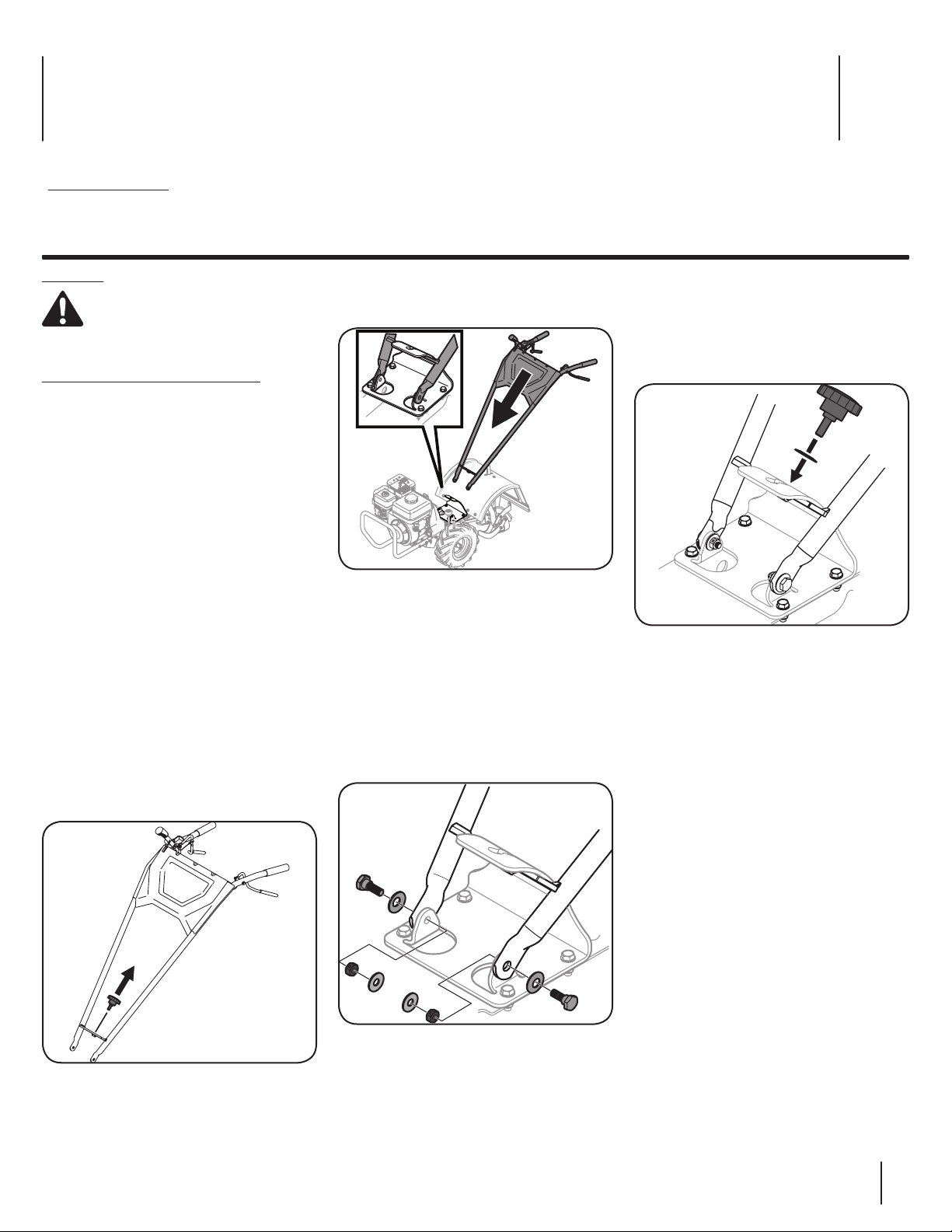
1. Remove the knob from the center of the
lower end of the handle by rotating it
counter-clockwise. See Figure 3-1.
Figure 3-1
2. Cut the large, plastic cable ties that secure the
handlebar ends to the handlebar mounting
tabs on the transmission top cover.
3. Gently lift the handlebar (do not overstretch
the attached cables) and place the handlebar
cross-brace in front of the curved height
adjustment bracket. See Figure 3-2.
Figure 3-2
4. With the forward clutch cable on the inside of
the handlebar, position the handlebar ends
on the outside of the two mounting tabs atop
the transmission cover. See inset in Figure 3-2.
5. Loosely attach the handlebars to the
mounting tabs with two shoulder screws
(.437 x .268: 5/16 - 18), inserted through two
Belleville washers (.450 x 1.0 x .062), then
through the lower ends of the handle and the
front holes on the bracket. Add flat washers
(.349 x .879 x .063) on the ends of each and
secure them by threading a hex lock nut
(5/16-18) on each end. See Figure 3-3.
Figure 3-3
Contents of Carton
• Tiller (1) • Handlebar Support (1) • Handlebar Assembly (1)
• Hardware Pack (1) • Operator’s Manual (1) • Engine Operator’s Manual (1)
6. Make sure the handlebar cross-brace is under
the bracket. Move the handlebars up or down
to align the threaded hole in the cross brace
with one of the three slots in the curved
height adjustment bracket.
7. Thread the height adjustment knob through the
washer (.760 x 1.250 x .041) then into the hole in
the handlebar cross-brace. See Figure 3-4.
Figure 3-4
8. Securely tighten the height adjustment screw.
9. Securely tighten the shoulder screws and
hex lock nuts from step 5 on the ends of the
handlebar.
10. To remove the tiller from its shipping
platform, first carefully unwrap the wheel
gear cable with the attached lever from
around the chassis. Move the neutral
ENGAGE/DISENGAGE lever to the DISENGAGE
position. This allows the wheels to rotate
freely.
NOTE: See Controls and Operation section for
location and operation instructions.
11. Use the handlebars to roll the tiller off the
platform.
NOTE: Use the DISENGAGE position to move
this tiller only when the engine is not running.
Before starting the engine, the neutral
ENGAGE/DISENGAGE lever must be placed
in the ENGAGE position (see the Controls &
Operation Section for details).
Loading ...
Loading ...
Loading ...