PRO TOOLS | CARBON Guide

Legal Notices
© 2020 Avid Technology, Inc., (“Avid”), all rights reserved. This guide may not be duplicated in whole or in part without the written consent of Avid.
For a current and complete list of Avid trademarks visit:
www.avid.com/legal/trademarks-and-other-notices.
Bonjour, the Bonjour logo, and the Bonjour symbol are trademarks of Apple Computer, Inc.
Thunderbolt and the Thunderbolt logo are trademarks of Intel Corporation in the U.S. and/or other countries.
This product may be protected by one or more U.S. and non-U.S. patents. Details are available at
www.avid.com/patents.
Product features, specifications, system requirements, and availability are subject to change without notice.
This product incorporates JetPLL™ clocking technologies, used under license from Sonopsis. JetPLL™ designs are covered by Sonopsis copyright and/or multiple
patents. The JetPLL™ word and logo are trademarks of Sonopsis. More information can be found at the JetPLL.info website:
http://JetPLL.info.
Guide Part Number 9329-66183-00 REV A 11/20
Pro Tools | Carbon Guide iii
Safety Instructions
Read and Keep these Instructions
Product Safety Warning
Important Safety Instructions
1 Read these instructions.
2 Keep these instructions.
3 Heed all warnings.
4 Follow all instructions.
5 Do not use this equipment near water.
6 Clean only with dry cloth.
7 Do not block any ventilation openings. Install in accordance with the manufacturer's instructions.
8 Do not install near any heat sources such as radiators, heat registers, stoves, or other equipment (including amplifiers) that pro- duce
heat.
9 Protect power cords from being walked on or pinched particularly at plugs, convenience receptacles, and the point where they exit
from the equipment.
10 Only use attachments/accessories specified by the manufacturer.
11 For products that are not rack mountable: Use only with a cart, stand, tripod, bracket, or table specified by the manufacturer, or sold
with the equipment. When a cart is used, use caution when moving the cart/equipment combination to avoid injury from tip-over.
12 Unplug this equipment during lightning storms or when unused for long periods of time.
13 Refer all servicing to qualified service personnel. Servicing is re- quired when the equipment has been damaged in any way, such as
power-supply cord or plug is damaged, liquid has been spilled or objects have fallen into the equipment, the equipment has been ex-
posed to rain or moisture, does not operate normally, or has been dropped.
14 For products that are a Mains powered device:
The equipment shall not be exposed to dripping or splashing and no objects filled with liquids (such as vases) shall be placed on the
equipment.
WARNING! To reduce the risk of fire or electric shock, do not expose this equipment to rain or moisture.
Do not defeat the safety purpose of the polarized or grounding-type plug. A polarized plug has two blades with one wider than the other.
A grounding type plug has two blades and a third grounding prong. The wide blade or the third prong are provided for your safety. If
the provided plug does not fit into your outlet, consult an electrician for replacement of the obsolete outlet.

Pro Tools | Carbon Guide iv
15 For products containing a lithium battery:
CAUTION! Danger of explosion if battery is incorrectly replaced. Replace only with the same or equivalent type.
16 For products with a power switch: It should remain accessible after installation.
17 The equipment shall be used at a maximum ambient temperature of 40' C.
18 This unit is provided with a power supply cord set suitable for 120V AC input only (for U.S.A. and Canada). For other than U.S.A.
and Canada, a qualified person must provide for use with this unit, an appropriate, approved power supply cord set which is in com-
pliance with the end use country requirements and has a minimum cross-sectional area of 1.0mm2.
19 For products with more than one power cord:
CAUTION: This unit has more than one power supply cord. Disconnect two power supply cords before servicing to avoid electrical
shock.
ATTENTION: Cet appareil comporte plus d’un cordon d’alimentation. Afin de prévenir les chocs électriques, débrancher les deux cor-
dons d’alimentation avant de faire le dépannage.
20 For products with an operator-accessible fuse:
CAUTION: For continued protection against risk of fire, replace only with same type and rating of fuse.
ATTENTION: Pour ne pas compromettre la protection contre les risques d’incendie, remplacer par un fusible de même type et de même
caractéristiques nominales.
Rack Mount Safety Instructions
1 Elevated Operating Ambient—If installed in a closed or multi-unit rack assembly, the operating ambient temperature of the rack en-
vironment might be greater than room ambient. Therefore, consider installing the equipment in an environment compatible with the
maximum ambient temperature (Tma) specified by the manufacturer.
2 Reduced Air Flow—Installation of the equipment in a rack should be such that the amount of air flow required for safe operation of
the equipment is not compromised. Make allowances for cooling air to be available to the front panel surface and no restrictions at
the rear.
3 Mechanical Loading—Mounting of the equipment in the rack should be such that a hazardous condition is not achieved due to un-
even mechanical loading.
4 Circuit Overloading—Consideration should be given to the connection of the equipment to the supply circuit and the effect that over-
loading of the circuits might have on over-current protection and supply wiring. Appropriate consideration of equipment nameplate
ratings should be used when addressing this concern.
5 Reliable Earthing—Reliable Earthing of rack mounted equipment should be maintained. Particular attention should be given to sup-
ply connections other than direct connections to the branch circuit (for example, use of power strips).
LED Safety Notices
Avid hardware might contain LED or Laser devices for communication use. These devices are compliant with the requirements for
Class 1 LED and Laser Products and are safe in the intended use. In normal operation the output of these laser devices does not exceed
the exposure limit of the eye and cannot cause harm.
Pro Tools | Carbon Guide v
Environmental Compliance
Proposition 65 Warning
Warning
This product can expose you to chemicals including Pb and Pb compounds, which is known to the State of California
to cause cancer and birth defects or other reproductive harm. For more information go to www.P65Warnings.ca.gov.
Perchlorate Notice
This product may contain a lithium coin battery. The State of California requires the following disclosure statement: “Perchlorate Ma-
terial—special handling may apply, see www.dtsc.ca.gov/hazardous waste/perchlorate.”
Recycling Notice
Disposal of Waste Equipment by Users in the European Union
This symbol on the product or its packaging indicates that this product must not be disposed of with other waste. Instead, it is your re-
sponsibility to dispose of your waste equipment by handing it over to a designated collection point for the recycling of waste electrical
and electronic equipment. The separate collection and recycling of your waste equipment at the time of disposal will help conserve nat-
ural resources and ensure that it is recycled in a manner that protects human health and the environment. For more information about
where you can drop off your waste equipment for recycling, please contact your local city recycling office or the dealer from whom you
purchased the product.
EMC (Electromagnetic Compliance)
Avid declares that this product complies with the following standards:
• FCC Part 15 Class A
• ICES-003 Class A
• EN 55032 Class A
• AS/NZS CISPR 32 Class A
• CISPR32 Class A
• EN 61000-3-2
• EN 61000-3-3
• EN 55035
• EN 55103-2 E2, E3, E4
Pro Tools | Carbon Guide vi
FCC N otic e: Class A Equipment
This equipment has been tested and found to comply with the limits for a Class A digital device, pursuant to Part 15 of the FCC rules.
These limits are designed to provide reasonable protection against harmful interference when the equipment is operated in a commercial
environment. This equipment generates, uses, and can radiate radio frequency energy and, if not installed and used in accordance with
the instructions, may cause harmful interference to radio communications. Operation of this equipment in a residential area is likely to
cause harmful interference, in which case the user will be required to correct the interference at personal expense.
Cable s
Connections to Avid hardware must be made with shielded cables with metallic RFI/EMI connector hoods in order to maintain com-
pliance with FCC Rules and Regulations.
Any modifications to the unit, unless expressly approved by Avid, could void the user's authority to operate the equipment.
Cana dian ICES-003 Cla ss A Not ice
This Class A digital apparatus complies with Canadian ICES-003.
Cet appareil numérique de la classe A est conforme à la norme NMB-003 du Canada.
Australian Com pliance
Kore an EMC Complia nce
㧊 ₆₆⓪ 㠛ⶊ㣿(A ) 㩚㧦䕢㩗䞿₆₆⪲㍲ 䕦ⰺ㧦 ⡦⓪ ㌂㣿㧦⓪ 㧊 㩦㦚 㭒㦮䞮㔲₆ ⧒Ⳇ, Ṗ㩫㣎㦮 㰖㡃㠦㍲ ㌂㣿䞮
⓪ ộ㦚 ⳿㩗㦒⪲ 䞿┞┺.
Safety Com plia nce
This equipment has been tested to comply with USA, Canadian, EU and International safety certification standards: UL 60065:2015,
CAN/CSA C22.2 No. 60065:16, IEC/EN 60065:2014 (8th Edition), UL 62368-1:2014, CAN/CSA 62368-1-14 and IEC/EN
62368-1:2014 (2nd Edition)
Avid Technology Inc., has been authorized to apply the appropriate NRTL mark on its compliant equipment.
Pow er Safe ty I nput Rating
Regulatory Model Number (RMN) 9100-74077: AC~100-240V, 50-60Hz, 1.0A
CE Compliance
(EMC, Safety and RoHS)
Avid is authorized to apply the CE (Conformite Europenne) mark on this compliant equipment thereby declaring conformity to EMC
Directive 2014/30/EU, Low Voltage Directive 2014/35/EU and RoHS Recast Directive 2011/65/EC.

Pro Tools | Carbon Guide vii
Appendix A. Safety Instructions. . . . . . . . . . . . . . . . . . . . . . . . . . . . . . . . . . . . . . . . . . . . . . . . . . . . . . . . . . . . . . . . . . . . . . . iii
Appendix B. Read and Keep these Instructions . . . . . . . . . . . . . . . . . . . . . . . . . . . . . . . . . . . . . . . . . . . . . . . . . . . . . . . . . . iii
Product Safety Warning . . . . . . . . . . . . . . . . . . . . . . . . . . . . . . . . . . . . . . . . . . . . . . . . . . . . . . . . . . . . . . . . . . . . . . . iii
Environmental Compliance . . . . . . . . . . . . . . . . . . . . . . . . . . . . . . . . . . . . . . . . . . . . . . . . . . . . . . . . . . . . . . . . . . . . . v
EMC (Electromagnetic Compliance) . . . . . . . . . . . . . . . . . . . . . . . . . . . . . . . . . . . . . . . . . . . . . . . . . . . . . . . . . . . . . . v
Introduction . . . . . . . . . . . . . . . . . . . . . . . . . . . . . . . . . . . . . . . . . . . . . . . . . . . . . . . . . . . . . . . . . . . . . . . . . . . . . . . . . . . . . . 1
Pro Tools | Carbon . . . . . . . . . . . . . . . . . . . . . . . . . . . . . . . . . . . . . . . . . . . . . . . . . . . . . . . . . . . . . . . . . . . . . . . . . . . 1
System Requirements and Compatibility Information . . . . . . . . . . . . . . . . . . . . . . . . . . . . . . . . . . . . . . . . . . . . . . . 2
Conventions Used in Pro Tools Documentation. . . . . . . . . . . . . . . . . . . . . . . . . . . . . . . . . . . . . . . . . . . . . . . . . . . . 2
Resources. . . . . . . . . . . . . . . . . . . . . . . . . . . . . . . . . . . . . . . . . . . . . . . . . . . . . . . . . . . . . . . . . . . . . . . . . . . . . . . . . . 3
Installation and Setup . . . . . . . . . . . . . . . . . . . . . . . . . . . . . . . . . . . . . . . . . . . . . . . . . . . . . . . . . . . . . . . . . . . . . . . . . . . . . 4
What’s in the Box? . . . . . . . . . . . . . . . . . . . . . . . . . . . . . . . . . . . . . . . . . . . . . . . . . . . . . . . . . . . . . . . . . . . . . . . . . . . 4
Rack Mounting Pro Tools | Carbon . . . . . . . . . . . . . . . . . . . . . . . . . . . . . . . . . . . . . . . . . . . . . . . . . . . . . . . . . . . . . . 4
Connecting Cables . . . . . . . . . . . . . . . . . . . . . . . . . . . . . . . . . . . . . . . . . . . . . . . . . . . . . . . . . . . . . . . . . . . . . . . . . . . 5
Register Pro Tools | Carbon and Activate your Avid Master Account. . . . . . . . . . . . . . . . . . . . . . . . . . . . . . . . . . . 6
Download and Install Software . . . . . . . . . . . . . . . . . . . . . . . . . . . . . . . . . . . . . . . . . . . . . . . . . . . . . . . . . . . . . . . . . 6
AVB Connections and Settings . . . . . . . . . . . . . . . . . . . . . . . . . . . . . . . . . . . . . . . . . . . . . . . . . . . . . . . . . . . . . . . . . 7
Launch Pro Tools . . . . . . . . . . . . . . . . . . . . . . . . . . . . . . . . . . . . . . . . . . . . . . . . . . . . . . . . . . . . . . . . . . . . . . . . . . . . 9
Starting Up or Shutting Down Your System . . . . . . . . . . . . . . . . . . . . . . . . . . . . . . . . . . . . . . . . . . . . . . . . . . . . . . 10
Pro Tools | Carbon Front Panel Operation . . . . . . . . . . . . . . . . . . . . . . . . . . . . . . . . . . . . . . . . . . . . . . . . . . . . . . . . . 11
Pro Tools | Carbon Front Panel . . . . . . . . . . . . . . . . . . . . . . . . . . . . . . . . . . . . . . . . . . . . . . . . . . . . . . . . . . . . . . . . 11
Configuring Inputs . . . . . . . . . . . . . . . . . . . . . . . . . . . . . . . . . . . . . . . . . . . . . . . . . . . . . . . . . . . . . . . . . . . . . . . . . . 14
Device Reset. . . . . . . . . . . . . . . . . . . . . . . . . . . . . . . . . . . . . . . . . . . . . . . . . . . . . . . . . . . . . . . . . . . . . . . . . . . . . . . 15
Pro Tools | Carbon Back Panel Connections . . . . . . . . . . . . . . . . . . . . . . . . . . . . . . . . . . . . . . . . . . . . . . . . . . . . . . . 16
Pro Tools | Carbon Back Panel . . . . . . . . . . . . . . . . . . . . . . . . . . . . . . . . . . . . . . . . . . . . . . . . . . . . . . . . . . . . . . . . 16
Digital I/O Connections . . . . . . . . . . . . . . . . . . . . . . . . . . . . . . . . . . . . . . . . . . . . . . . . . . . . . . . . . . . . . . . . . . . . . . 16
Analog I/O Connections . . . . . . . . . . . . . . . . . . . . . . . . . . . . . . . . . . . . . . . . . . . . . . . . . . . . . . . . . . . . . . . . . . . . . . 17
Footswitch . . . . . . . . . . . . . . . . . . . . . . . . . . . . . . . . . . . . . . . . . . . . . . . . . . . . . . . . . . . . . . . . . . . . . . . . . . . . . . . . 17
Configuring Pro Tools. . . . . . . . . . . . . . . . . . . . . . . . . . . . . . . . . . . . . . . . . . . . . . . . . . . . . . . . . . . . . . . . . . . . . . . . . . . . 18
Playback Engine. . . . . . . . . . . . . . . . . . . . . . . . . . . . . . . . . . . . . . . . . . . . . . . . . . . . . . . . . . . . . . . . . . . . . . . . . . . . 18
Hardware Setup . . . . . . . . . . . . . . . . . . . . . . . . . . . . . . . . . . . . . . . . . . . . . . . . . . . . . . . . . . . . . . . . . . . . . . . . . . . . 19
I/O Setup . . . . . . . . . . . . . . . . . . . . . . . . . . . . . . . . . . . . . . . . . . . . . . . . . . . . . . . . . . . . . . . . . . . . . . . . . . . . . . . . . . 23
Contents

Pro Tools | Carbon Guide
viii
DSP Mode for Low-Latency Monitoring . . . . . . . . . . . . . . . . . . . . . . . . . . . . . . . . . . . . . . . . . . . . . . . . . . . . . . . . . . . . 25
Enabling DSP Mode . . . . . . . . . . . . . . . . . . . . . . . . . . . . . . . . . . . . . . . . . . . . . . . . . . . . . . . . . . . . . . . . . . . . . . . . . 26
Enabling DSP Mode Safe . . . . . . . . . . . . . . . . . . . . . . . . . . . . . . . . . . . . . . . . . . . . . . . . . . . . . . . . . . . . . . . . . . . . . 27
Indicators for DSP Plug-ins, Inserts, Sends, and Outputs . . . . . . . . . . . . . . . . . . . . . . . . . . . . . . . . . . . . . . . . . . . 27
System Usage . . . . . . . . . . . . . . . . . . . . . . . . . . . . . . . . . . . . . . . . . . . . . . . . . . . . . . . . . . . . . . . . . . . . . . . . . . . . . . 30
Enable DSP Mode Preference . . . . . . . . . . . . . . . . . . . . . . . . . . . . . . . . . . . . . . . . . . . . . . . . . . . . . . . . . . . . . . . . . 30
Workflow Example: Recording in DSP Mode for Low-Latency Monitoring . . . . . . . . . . . . . . . . . . . . . . . . . . . . . . 31
Tips for Using DSP Mode . . . . . . . . . . . . . . . . . . . . . . . . . . . . . . . . . . . . . . . . . . . . . . . . . . . . . . . . . . . . . . . . . . . . . 35
Appendix C. Specifications. . . . . . . . . . . . . . . . . . . . . . . . . . . . . . . . . . . . . . . . . . . . . . . . . . . . . . . . . . . . . . . . . . . . . . . . . . 36
Audio Specifications . . . . . . . . . . . . . . . . . . . . . . . . . . . . . . . . . . . . . . . . . . . . . . . . . . . . . . . . . . . . . . . . . . . . . . . . 36
Mechanical Specifications . . . . . . . . . . . . . . . . . . . . . . . . . . . . . . . . . . . . . . . . . . . . . . . . . . . . . . . . . . . . . . . . . . . . 39
Environmental Specifications . . . . . . . . . . . . . . . . . . . . . . . . . . . . . . . . . . . . . . . . . . . . . . . . . . . . . . . . . . . . . . . . . 39
Appendix D. Pro Tools | Carbon Core Audio Devices . . . . . . . . . . . . . . . . . . . . . . . . . . . . . . . . . . . . . . . . . . . . . . . . . . . . 40
Pro Tools | Carbon: I/O . . . . . . . . . . . . . . . . . . . . . . . . . . . . . . . . . . . . . . . . . . . . . . . . . . . . . . . . . . . . . . . . . . . . . . . 40
Pro Tools | Carbon: Reserved for Pro Tools . . . . . . . . . . . . . . . . . . . . . . . . . . . . . . . . . . . . . . . . . . . . . . . . . . . . . . 41
AVB Device Configuration . . . . . . . . . . . . . . . . . . . . . . . . . . . . . . . . . . . . . . . . . . . . . . . . . . . . . . . . . . . . . . . . . . . . 41
AVB Channel to Physical I/O Mappings for the Pro Tools | Carbon: I/O Device . . . . . . . . . . . . . . . . . . . . . . . . . . 44
Appendix E. Pro Tools | Carbon Pin Out Diagrams . . . . . . . . . . . . . . . . . . . . . . . . . . . . . . . . . . . . . . . . . . . . . . . . . . . . . . 46
Ethernet, RJ45 Connector, Gigabit . . . . . . . . . . . . . . . . . . . . . . . . . . . . . . . . . . . . . . . . . . . . . . . . . . . . . . . . . . . . . 46
DB25 Pin Out Connections Channels 1–8 . . . . . . . . . . . . . . . . . . . . . . . . . . . . . . . . . . . . . . . . . . . . . . . . . . . . . . . . 46
Appendix F. Network Port Usage . . . . . . . . . . . . . . . . . . . . . . . . . . . . . . . . . . . . . . . . . . . . . . . . . . . . . . . . . . . . . . . . . . . . . 47
Required Access for Normal Operation. . . . . . . . . . . . . . . . . . . . . . . . . . . . . . . . . . . . . . . . . . . . . . . . . . . . . . . . . . 47
Access for Customer Support . . . . . . . . . . . . . . . . . . . . . . . . . . . . . . . . . . . . . . . . . . . . . . . . . . . . . . . . . . . . . . . . . 47
Network Security . . . . . . . . . . . . . . . . . . . . . . . . . . . . . . . . . . . . . . . . . . . . . . . . . . . . . . . . . . . . . . . . . . . . . . . . . . . 47

Introduction
1
Introduction
Pro Tools | Carbon
Welcome to Pro Tools | Carbon
™
by Avid
®
. Pro Tools | Carbon is a versatile multi-channel audio interface for use with Pro Tools
®
and Pro Tools | Ultimate
™
software or other Core Audio–compatible software. It provides exceptional AD/DA audio conversion with
8 mic/line inputs (combo XLR/TRS or DB25), 2 instrument inputs (TS), 8 line outputs (DB25), 2 dedicated outputs for stereo monitor-
ing (TRS), 4 independent headphone outputs, an integrated talkback mic, ADAT
™
I/O, Word Clock, AVB, and dedicated HDX DSP
for low-latency monitoring with AAX DSP plug-ins.
Pro Tools | Carbon Features
Pro Tools | Carbon provides:
• Up to 192 kHz/32-bit AD/DA conversion
• Low latency tracking workflows with on-board HDX DSP
• 8 analog preamp inputs with
• Variable Z (impedance) on INST inputs 1–2 (front panel)
• Variable Z (impedance) on MIC inputs 5–8 (back panel)
• 8 line inputs (DB25 or TRS 1/4-inch) with
• True preamp bypass option
• 18 channels digital-to-analog conversion
• 8 line outputs (DB25)
• Dedicated stereo (L–R) monitor outputs (TRS 1/4-inch)
• 4 stereo headphone outputs
• ADAT I/O
• 16 channels at 44.1/48 kHz
• 8 channels at 88.2/96 kHz
• 4 channels at 176.4/192 kHz
• 8 channel I/O metering
• Stereo monitor output metering
• Front panel control over monitor sets, headphone outputs, input channel settings, input and output metering, and talkback mic
• Integrated talkback mic
• Footswitch to toggle talkback on and off
• Gigabit AVB-capable Ethernet
Introduction
2
Included Software, Plug-ins, and Sound Libraries
With your purchase and registration of Pro Tools | Carbon, you are entitled to the following:
• Pro Tools software, with:
• 1-year subscription with a “perpetual parachute” (an off-plan perpetual license)
• Standard Avid support contract
• Bundled effects and instrument plug-ins from Avid and several of our Development Partners.
• Sound libraries that include samples for almost all of your music production needs, including sound effects, hits, loops, and phrases
of a wide variety of instruments, a range of tempo options (for rhythmic material), in many different styles.
System Requirements and Compatibility Information
Pro Tools | Carbon is supported by Pro Tools and Pro Tools | Ultimate 2020.11 or later.
For detailed Pro Tools | Carbon system requirements, visit
www.avid.com/carbon-support.
Avid can only assure compatibility and provide support for hardware and software it has tested and approved.
For a complete list of optimizations for your Pro Tools computer, visit:
Pro Tools Computer Optimizations.
For complete Pro Tools system requirements and a list of qualified computers, operating systems, hard drives, peripherals, and
third-party devices, visit
www.avid.com/compatibility.
Conventions Used in Pro Tools Documentation
Pro Tools documentation uses the following conventions to indicate menu choices, keyboard commands, and mouse commands:
:
The names of Commands, Options, and Settings that appear on-screen are in a different font.
The names of physical controls on Pro Tools | Carbon are in displayed in bold text.
Hyper-links and cross-reference links are displayed
in blue text.
The following symbols are used to highlight important information:
For complete, detailed information about what you get with Pro Tools | Carbon, visit
www.avid.com/carbon-support.
If your computer only has Thunderbolt ports, an Avid-qualified AVB-capable Thunderbolt to Ethernet adapter is required.
Convention Action
File > Save Choose Save from the File menu
Command+N Hold down the Command key and press the N key
Command-click Hold down the Command key and click the mouse button
Right-click Click with the right mouse button
User Tips are helpful hints for getting the most from your Pro Tools system.
Important Notices include information that could affect your Pro Tools session data or the performance of your Pro Tools system.
Shortcuts show you useful keyboard or mouse shortcuts.
Cross References point to related sections in this guide and other Avid documentation.

Introduction
3
Resources
The Avid website (www.avid.com) is your best online source for information to help you get the most out of your Avid system.
Account Activation and Product Registration
Activate your product to access downloads in your Avid account (or quickly create an account if you do not have one). Register your
purchase online, download software, updates, documentation, and other resources.
www.avid.com/account
Support and Downloads
Contact Avid Customer Success (technical support), download software updates and the latest online manuals, browse the Compatibil-
ity documents for system requirements, search the online Knowledge Base or join the worldwide Avid user community on the User Con-
ference.
www.avid.com/support
Training and Education
Study on your own using courses available online, find out how you can learn in a classroom setting at an Avid-certified training center,
or view video tutorials and webinars.
www.avid.com/education
Video Tutorials
The Get Started Fast with Pro Tools series of online videos provide tutorials to help if you are new to Pro Tools. Videos for the expe-
rienced user that introduce new features found in the latest versions of Pro Tools are also available.
www.avidblogs.com/get-started-fast-with-pro-tools
View Pro Tools Tech Tips on YouTube for the latest tips and tricks with Pro Tools.
For Pro Tools | Carbon–specific tutorials, visit
www.avid.com/carbon-support.
Products and Developers
Learn about Avid products, download demo software, or learn about our Development Partners and their plug-ins, applications, and
hardware.
www.avid.com/products
Avid Store
Visit the Avid store for plug-ins and control surfaces to extend the capabilities of your Pro Tools | Carbon system.
shop.avid.com
For more information about specific AAX Native/DSP plug-ins for use with Pro Tools | Carbon in DSP Mode, visit
www.avid.com/products/pro-tools-carbon/aax-dsp-plugins.

Installation and Setup
4
Installation and Setup
Installing and setting up Pro Tools | Carbon involves the following:
1 Unpacking Pro Tools | Carbon from the box.
2 Rack mounting Pro Tools | Carbon (optional).
3 Connecting cables.
4 Registering Pro Tools | Carbon.
5 Downloading and installing Pro Tools and bundled software.
6 Authorizing your software with iLok License Manager.
7 Enabling AVB in Audio MIDI Setup.
8 Launching and configuring Pro Tools.
What’s in the Box?
Before you get started installing Pro Tools | Carbon, unpack the box, which contains the following:
• Pro Tools | Carbon audio interface
• Power cable
• Ethernet cable (CAT6)
• 4 rack mount screws with washers
• 4 adhesive rubber pads
• Welcome card with redemption code, QR code, and serial number
• Warranty Claims Information card
• Avid Health and Safety Guide
Keep the Welcome card on hand to register Pro Tools | Carbon and access software, sound libraries, and documentation downloads. Set
the cables aside until you are ready to start making cable connections. Remove Pro Tools | Carbon from the box and packaging, and
place it on a hard, dry surface.
Rack Mounting Pro Tools | Carbon
If you install Pro Tools | Carbon into a 19-inch rack, you can use the included rack mount screws and washers. Pro Tools | Carbon, as
with all Avid audio interfaces, needs room at the front and back of the unit to maintain proper air flow for cooling. Do not block the front
or back of the unit, or disconnect the internal fan. If the unit is rack mounted in a case, remove the case lids or doors before operating
the system. Failure to do so can result in the unit overheating, which can permanently damage sensitive components.
If you decide to not install Pro Tools | Carbon in a rack, you can affix the included adhesive rubber pads to the bottom of the unit to pro-
tect whatever surface you decide to set it on (for example, if you decide to use it as a desktop unit).

Installation and Setup
5
Connecting Cables
Once you have installed Pro Tools | Carbon in a rack (optional), you are ready to start connecting cables.
Connect Power
Connect the included power cable to Pro Tools | Carbon. Then connect the cable to a grounded AC power outlet. It is recommended that
you use a grounded power switch or power conditioner.
Connect Ethernet
Connect Pro Tools | Carbon Ethernet port 1 or 2 directly to your computer using the included Ethernet cable.
If your computer only has Thunderbolt ports, use an AVB-capable Thunderbolt to Ethernet adapter.
Thunderbolt 2
Use an AVB-capable Thunderbolt 2-to-Gigabit Ethernet adapter, such as the Apple Thunderbolt to Gigabit Ethernet
Adapter.
Thunderbolt 3 (USB-C)
Use an AVB-capable Thunderbolt 3-to-Gigabit Ethernet adapter, such as the Apple Thunderbolt 3 (USB-C) to
Thunderbolt 2 Adapter connected to the Apple Thunderbolt to Gigabit Ethernet Adapter.
Connect Audio
Make sure that your sound system is powered off. Make the appropriate analog and digital audio cable connections for your system. In
addition to the digital and analog inputs and outputs on the back panel, there are two quarter-inch jacks for instrument input on the front
panel. The front panel also provides four 1/4-inch headphone jacks.
Connect Clock Sync
If you are installing Pro Tools | Carbon in a system with multiple audio interfaces and/or a synchronization peripheral, make the appro-
priate Word Clock connections using shielded BNC cables (not included) or connections for clocking over ADAT using optical cables
(not included).
Connect a Footswitch
(Optional)
You can connect an optional footswitch (not included) to the back of Pro Tools | Carbon (1/4-inch jack) to toggle talkback on and off.
Both momentary/latching and normally open/normally closed footswitches are supported.
In order to meet EMC requirements and in order to obtain the highest performance of Pro Tools | Carbon, use high-quality, properly
shielded cables for all external connections.
To orient yourself with Pro Tools | Carbon front panel connections, see
Pro Tools | Carbon Front Panel.
For information about back panel connections, see Pro Tools | Carbon Back Panel Connections.
A direct Network Interface connection between Pro Tools | Carbon and your computer is required. Network equipment such as routers,
hubs, and switches are not supported.
Not all Thunderbolt to Ethernet adapters are AVB-capable. For the latest compatibility information and system requirements, visit
www.avid.com/carbon-support.
When using Pro Tools | Carbon with EUCON peripherals (such as S1), use a dedicated Network Interface to your Mac for
Pro Tools | Carbon.

Installation and Setup
6
Register Pro Tools | Carbon and Activate your Avid Master Account
Pro Tools | Carbon includes a Welcome card with a redemption code and a QR code that lets you register the unit. Registering lets you
access software and PDF documentation through your online Avid Master Account.
To register your Pro Tools | Carbon unit and access Pro Tools | Carbon-related downloads through your Avid Master Account:
1 Locate the Welcome card.
2 Do one of the following:
• With your mobile device, scan the QR code on the Welcome card. Follow the on-screen instructions and then continue with the
next step.
•Visit
https://www.avid.com/register and continue with the next step.
3 Log in to your Avid Master Account. If you do not already have an Avid Master Account, create a new one and log in.
4 Enter the redemption code on the Welcome card and click Register. If you scanned the QR code, your redemption code is entered au-
tomatically.
5 Select your iLok.com account and click Use This Account, or create a new iLok account by following the on-screen instructions.
You are directed to the My Products page for your Avid Master Account.
Download and Install Software
Once you have registered Pro Tools | Carbon, you can download and install Pro Tools software, including plug-ins, and sound libraries,
from your Avid Master Account. PDF documentation for Pro Tools | Carbon and Pro Tools software is also available through your Avid
Master Account.
Download and Review PDF Documentation
Download and review PDF documentation for Pro Tools | Carbon and Pro Tools software from your Avid Master Account. Be sure to
consult any Read Me documentation for the latest known issues.
Download and Install Pro Tools Software
To download Pro Tools software:
1 From the computer where you will be installing Pro Tools, log in to your Avid Master Account (if you are not already).
2 Under My Products, locate and click Pro Tools | Carbon in the Products list.
3 Click the View Software Download Links & Product Details link to show download links for all software installers and PDF doc-
umentation included with Pro Tools | Carbon.
4 Download the Pro Tools installer.
5 Locate and launch the downloaded installer.
6 Follow the on-screen instructions to complete the installation.
7 Download and install plug-ins and sound libraries bundled with Pro Tools | Carbon from your Avid Master Account (you can also do
this using the Avid Link desktop application that is installed with Pro Tools).
8 Before launching Pro Tools for the first time, enable AVB for Pro Tools | Carbon in Audio MIDI Setup (see AVB Connections and
Settings
).
If you are an existing customer who already owns an eligible Pro Tools product, you may choose between getting an additional
Pro Tools license or extending the duration of the term of your current product.
Installation and Setup
7
AVB Connections and Settings
Pro Tools | Carbon requires a direct connection to your computer using AVB Ethernet. The AVB Ethernet connection provides up to 56
input channels and 84 output channels of AVB audio between Pro Tools | Carbon and Pro Tools, and up to 28 input channels and 28 out-
put channels of AVB audio between Pro Tools | Carbon and third-party Core Audio–compatible software. The number of available AVB
input and output channels is reduced at higher sample rates.
Before you can use Pro Tools | Carbon with your Mac, do each of the following:
Make sure you have met all the System Requirements (see
System Requirements and Compatibility Information).
Make sure that you have connected Pro Tools | Carbon to your computer using a direct connection to one of the computer's
Ethernet ports or Thunderbolt ports using an AVB-capable Thunderbolt adapter (see Connect Ethernet).
Enable AVB in Audio MIDI Setup (see Enable AVB).
Select Pro Tools | Carbon as the Pro Tools Playback Engine (Setup > Playback Engine) (see Playback Engine).
Update Pro Tools | Carbon firmware when prompted. This is absolutely required for your system to perform properly
(see Firmware Update).
Enable AVB
To enable AVB on the Pro Tools computer:
1 Make sure Pro Tools | Carbon is connected by Ethernet to your computer and that both are powered on.
2 Go to Applications > Utilities and launch Audio MIDI Setup (AMS).
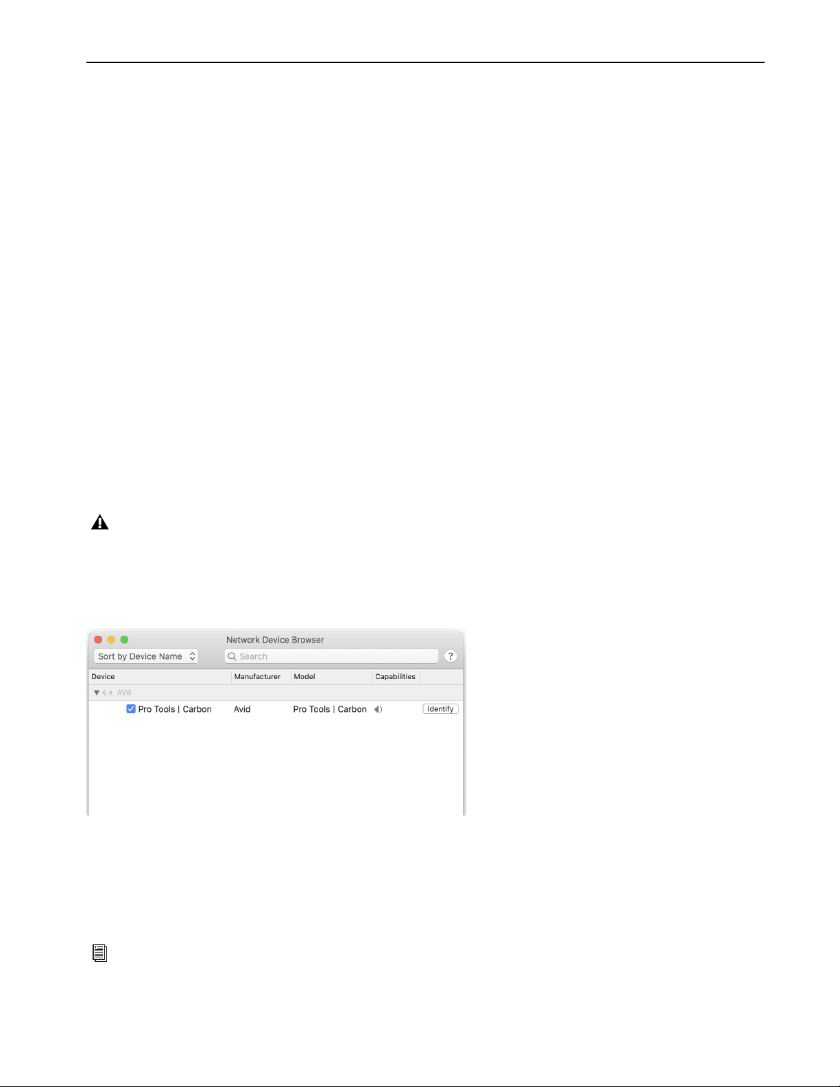
3 In Audio MIDI Setup, choose Window > Show Network Device Browser (or press Command+3). If Pro Tools | Carbon is correctly
connected and powered-on, it appears in the Device list as “Pro Tools | Carbon.”
4 Click to enable Pro Tools | Carbon in the Device list.
Pro Tools | Carbon Audio Devices in AMS
Pro Tools | Carbon presents two separate Audio Devices in the Audio Devices list in AMS:
• The Pro Tools | Carbon: I/O device for use with macOS System Sound and third-party Core Audio applications.
• The Pro Tools | Carbon: Reserved for Pro Tools device.
If Pro Tools | Carbon does not appear in the Network Device Browser, double check the Ethernet cable connections and make sure that
you are using an AVB-compatible connection (Ethernet port or qualified adapter) and that your Mac is AVB-compatible. In addition to
checking cable connections, you may need to disable any active VPN (depending on the specific VPN configuration) or network proxy.
For more information on troubleshooting Pro Tools | Carbon, visit
www.avid.com/carbon-support.
Pro Tools | Carbon enabled as a network audio device in AMS
For more information, see Pro Tools | Carbon Core Audio Devices.
Installation and Setup
8
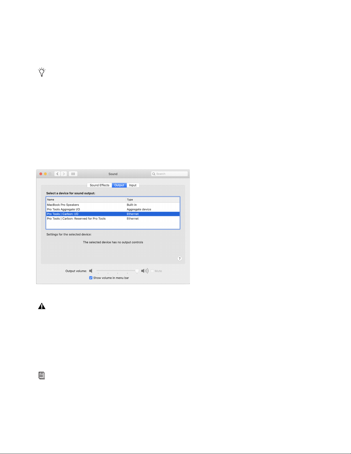
Setting Up Pro Tools | Carbon for macOS System Sound Input and Output
You can use Pro Tools | Carbon for macOS System Sound Input and Output. Select Pro Tools | Carbon: I/O as the Sound Input device
for recording audio with third-party Core Audio audio applications. Select Pro Tools | Carbon: I/O as the Sound Output device to play
back third-party Core Audio audio applications and websites through the Main Monitor (MON L–R) outputs on the back of Pro Tools
| Carbon as well as headphones that are assigned to the Main Monitor output path (configured in the Pro Tools Hardware Setup).
To set up Pro Tools | Carbon for macOS System Sound Input and Output:
1 Launch the macOS System Preferences.
2 Open the Sound preferences.
3 Click the Input tab.
4 In the device list, select Pro Tools | Carbon: I/O in the Device list.
5 Click the Output tab.
6 In the device list, select Pro Tools | Carbon: I/O in the Device list.
AVB Device Configuration in AMS
Pro Tools | Carbon provides six different device configurations for Pro Tools input and output channels. The selected configuration de-
termines the maximum sample rate and the complexity of DSP Mode track routing that is possible in Pro Tools. Certain configurations
also affect the number of available channels when using the Pro Tools | Carbon: I/O device with third-party Core Audio applications.
Use a smaller configuration to reduce the load on the host processor. Use a larger configuration to increase mixing capacity in Pro Tools
for more complex routing of low latency paths using DSP Mode.
You can use the Configure Speakers feature in AMS to change the Pro Tools | Carbon: I/O outputs that are used for macOS System
Sound or to configure the Pro Tools | Carbon: I/O for greater-than-stereo formats. For AVB channel mappings to Pro Tools | Carbon
physical outputs, see
Pro Tools | Carbon Core Audio Devices.
Pro Tools | Carbon: I/O selected for macOS System Sound Output
Never use Pro Tools | Carbon: Reserved for Pro Tools for the macOS System Sound or other third-party audio applications.
Only use Pro Tools | Carbon: I/O for macOS System Sounds and other third-party audio applications.
For more information, see
AVB Device Configuration.
Installation and Setup
9
Launch Pro Tools
After you have installed Pro Tools software, bundled plug-ins, and sound libraries, and have enabled AVB for Pro Tools | Carbon,
launch Pro Tools. When launching Pro Tools for the first time, you are prompted to Activate your Pro Tools software license and
licenses for any newly installed plug-ins. Follow the on-screen instructions to activate your iLok licenses. You may also be prompted
to update the firmware for Pro Tools | Carbon.
To launch Pro Tools:
1 Double-click the Pro Tools icon in the Applications folder or single-click the icon in the Dock.
2 When prompted to Activate your Pro Tools software license, follow the on-screen instructions.
3 If you are prompted to update Pro Tools | Carbon Firmware, do so by following the on-screen instructions.
iLok Authorization
Once you have registered Pro Tools | Carbon and downloaded and installed software from your Avid Master Account, use iLok License
Manager to authorize iLok Cloud or your physical USB iLok (purchased separately) with your entitlements. When launching Pro Tools
for the first time, you are prompted to Activate your software license using your registered iLok account.
Firmware Update
Required firmware updates are included with Pro Tools software. When you first launch a new version of Pro Tools you may be
prompted to update the firmware for Pro Tools | Carbon. If prompted, follow the on-screen instructions to update Pro Tools | Carbon
firmware.
Note that if you launch Pro Tools, but Pro Tools | Carbon is not selected as the Playback Engine, you are prompted to update the firm-
ware for Pro Tools | Carbon when it is selected as the Playback Engine if necessary (see
Playback Engine).
Pro Tools application icon
Note that if you select Pro Tools | Carbon in the Playback Engine after Pro Tools is launched, you may be prompted to update the
firmware.
Press and hold the N key when launching Pro Tools to open the Playback Engine dialog. If Pro Tools | Carbon is not selected as
the Playback Engine, select it and click OK. Alternatively, you can select Pro Tools | Carbon in the Playback Engine after you have
launched Pro Tools (Setup > Playback Engine). For more information, see
Playback Engine.

Installation and Setup
10
Starting Up or Shutting Down Your System
To ensure that the components of your Pro Tools system communicate properly with each other, it is advised that you power them on
in the following order.
Start up your Pro Tools system in this order:
1 Make sure all your equipment (including your computer) is off.
2 Mute your Pro Tools | Carbon monitor speakers.
3 Lower the volume of all output devices in your system.
4 Turn on any external hard drives.
5 Turn on any control surfaces (such as S1).
6 Turn on any MIDI interfaces, MIDI devices, or synchronization peripherals.
7 Power on Pro Tools | Carbon. Wait at least fifteen seconds for your system hardware to initialize.
8 Turn on your computer.
9 Launch Pro Tools or any third-party audio or MIDI applications.
10 Unmute your Pro Tools | Carbon monitor speakers.
Shut down your Pro Tools system in this order:
1 Quit Pro Tools and any other running applications. To quit Pro Tools, choose Pro Tools > Quit (Mac) or File > Exit (Windows).
2 Mute your Pro Tools | Carbon monitor speakers.
3 Turn off or lower the volume of all output devices in your system.
4 Turn off your computer.
5 Turn off Pro Tools | Carbon (press and hold the power button for 2 seconds).
6 Turn off any MIDI interfaces, MIDI devices, or synchronization peripherals.
7 Turn off any control surfaces (such as S1).
8 Turn off any external hard drives.
The front panel display on Pro Tools | Carbon may contain some inconsistencies, such as incorrect colors or fields not illuminating,
until the device firmware has been updated by Pro Tools. See
Launch Pro Tools.

Pro Tools | Carbon Front Panel Operation
11
Pro Tools | Carbon Front Panel Operation
The front panel of Pro Tools | Carbon provides indicators and controls for input settings and monitoring functions.
Pro Tools | Carbon Front Panel
The front panel of Pro Tools | Carbon provides various jacks, controls, and indicators. To the left of the segmented I/O Meters are con-
trols and indicators for inputs, as well as 2 instrument input jacks. To the right of the I/O Meters are controls and indicators for moni-
toring outputs, as well as 4 headphone jacks.
1 INST inputs 1 and 2 (mono 1/4-inch unbalanced) — Connect instruments, such as guitars or keyboards. The INPUT setting automat-
ically switches to INST when a 1/4-inch cable is connected to the INST input jack. You can still switch the inputs to MIC or LINE
(back panel inputs 1 and 2) while an instrument is plugged into either of the front panel INST inputs.
2 Talkback Mic — The built-in talkback mic is located within a small hole to the right of the INST inputs. In Pro Tools, you can route
the Talkback signal to any output using an Auxiliary Input track. To use the talkback mic with third-party audio software, use the AVB
channel for the talkback mic (for AVB channel mappings, see
Pro Tools | Carbon Core Audio Devices).
3 NET indicator — Indicates the status of the AVB connection to host computer. It lights white when the device is connected using
AVB and recognized by your computer.
4 EXT indicator — Indicates status of the external clock. It lights green when either ADAT or Word Clock is the selected clock source
and the clock is valid. It flashes green when either ADAT or Word Clock is the selected clock source and clock is not valid (internal
clocking is used instead).
5 Power button — The power button lights amber when connected to power, but not powered on. It lights white when powered on. It
is unlit when power is disconnected. Press and hold the button for two seconds to power off the unit.
6 Input Level Strip and Input Source — Displays the input source (MIC, LINE, or INST) for the selected input channel. The Input Level
Strip displays the amount of gain (preamp) applied to the selected input channel. The Input Level Strip LEDs light green when the
selected input channel is set to
MIC, yellow when the selected input channel is set to LINE, and amber when the selected input chan-
nel is set to INST. When an input channel is set to LINE and the preamp is bypassed, the Input Level Strip fully lights. Increase the
gain for the selected input channel by turning the encoder dial (7) clockwise—the LEDs light from left to right.
7 Input Encoder — Turn to adjust input gain for the selected input channel. Press the encoder to cycle through and select input channels
for encoder control focus. The Channel Number indicator for the selected channel lights green over the I/O Meters (14). You can also
press and hold the encoder while turning it clockwise or counter-clockwise to select channels. Linked channels are selected as a stereo
input pair when cycling through channels.
Pro Tools | Carbon front panel
For more information on configuring inputs, see
Configuring Inputs.
When Output metering is enabled, the input section is disabled and the relevant buttons are unlit except for the Talkback button.
Pressing any button or input encoder in the input section switches back to Input metering and re-activates the input section.
1 5
3
4
7
14 15
17
20 24 25
9 10 18 2322214
6
8 13
11 12 16
19a 19b
19c
2
Pro Tools | Carbon Front Panel Operation
12
8 Talkback button — A single press latches Talkback on (unmute the Talkback mic input). Press the button again to unlatch and turn
Talkback off (mute the Talkback mic input). Press and hold the Talkback button to engage Talkback temporarily and release to dis-
engage. The button flashes red when Talkback is engaged. DIM (24) is engaged while the talkback mic is active. You can also use a
Footswitch to engage and disengage Talkback (see
Footswitch).
9 Z button — Press to cycle through the available impedance settings (Variable Z) for the selected input (the Z button changes color
to indicate the impedance setting for the input):
•
MIC inputs 5–8 on the back panel.
• INST inputs 1–2 on the front panel
10 INPT (Input) button — Cycles between the available inputs for the selected channel: MIC, LINE, INST. Use the Input encoder button
(7) to select the desired input channel. The selected input channel lights above the I/O Meters (14).
11 LINK button — Links odd (left) and even (right) channel input pairs for stereo linking. When linked, preamp controls affect both
channels identically. The even channel inherits the settings of the odd channel settings when linked. When enabled, the LINK button
lights green.
12 Ø button — Toggles the polarity of the selected input channel. The button lights amber when the polarity is inverted.
13 48V— Press to enable or disable phantom power for the selected MIC input. Phantom power can only be enabled when there is an
XLR connection for the selected input. When phantom power is enabled for the selected input, the 48V button lights red. If there is
an XLR connection for the selected input and phantom power is disabled, the button lights white. The button is unlit when there is
no XLR connection, or if there is an XLR connection but the input is set to INST or LINE and phantom power is disabled.
For linked channels, phantom power behaves as follows:
• If both linked channels have XLR connections, phantom power works the same as with one channel.
• If only the first linked channel has an XLR connection, the
48V button lights white but pressing the button has no effect.
• If only the second linked channel has an XLR connection, the 48V button does not light.
• If either XLR connection is broken while phantom power is enabled on linked channels, phantom power is disabled for that channel.
• If the connection to the second linked channel is broken, the 48V button lights red and phantom power is disabled for the second
channel.
• If the connection to the first linked channel is broken, the
48V button does not light and phantom power remains on for the second
channel.
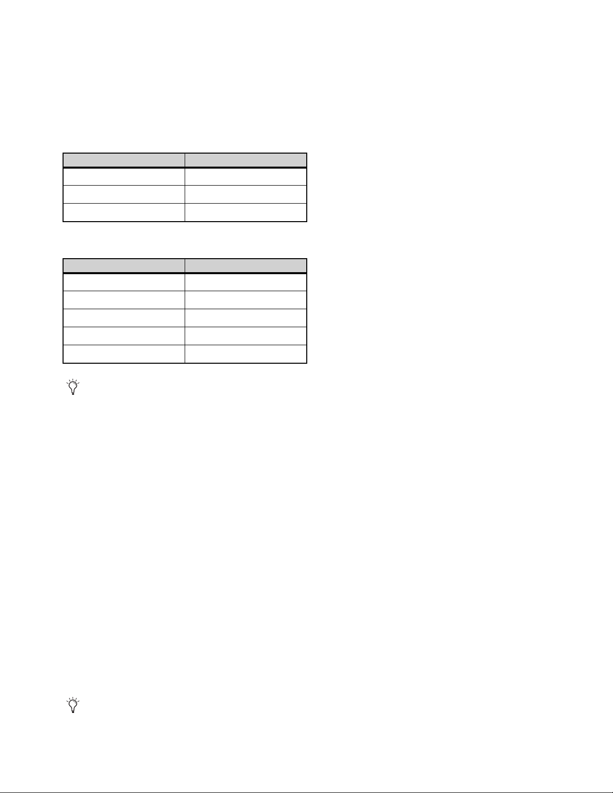
Variable impedances for Mic channel inputs 5–8
Impedance Color
5k Ohm White (default)
50k Ohm Cyan
1k Ohm Fuchsia
Variable impedances for Instrument channel inputs 1–2
Impedance Color
1M Ohm White (default)
230k Ohm Cyan
90k Ohm Blue
70k Ohm Violet
32k Ohm Fuchsia
Use Variable Z on INST inputs when connecting guitar or bass with passive pickups. Variable Z alters the frequency response by
loading the pickups in the same manner as plugging in to different real amps or effects.
Unlike other input channel parameters, phantom power is not restored when the device is powered off and back on. This protects
connected microphones and equipment which may be configured differently when the device is powered back on.
Pro Tools | Carbon Front Panel Operation
13
14 I/O Meters — 9-segment LED meters display peak metering with peak hold (3 seconds) for input or output channels. Above each me-
ter are Channel Number indicators for each I/O channel. Channel Number indicators for the selected channel (or channel pairs when
stereo linked) light green. Non-selected channels light white.
15 OUT button — Press to select analog output metering.
16 Meter button — Can be used to reset the device settings (see
Default Device Settings).
17 IN button — Press to select analog input metering.
18 Stereo Monitor Meter — This 9-segment LED stereo meter displays peak metering with peak hold for the output level of the selected
monitor or headphone output. Meter levels are pre-fader (showing the signal level before the monitor output control).
19 A, B, and C buttons — These three buttons are assigned to control the Main (MON L–R), Alt 1 (LINE 1–2), and Alt 2 (LINE 3–4)
monitor sets respectively. The buttons light white if the corresponding monitor set is available (enabled in the Pro Tools Hardware
Setup). The
A button lights green when selected, the B button yellow, and the C button amber. If a monitor set is not enabled in the
Pro Tools Hardware Setup, the corresponding button is unlit and the monitor set cannot be selected. Press the corresponding button
to select the desired monitor set and mute the other sets.
20 Output Encoder — Turning the knob increases or decreases the signal level for the currently selected monitor or headphone output.
Press the Output Encoder to change control to the next available monitor set or headphone output. Press and hold the Output Encoder
while rotating to cycle control through the available monitor sets or headphone outputs.
21 Output Level Strip and Monitor Indicators — The Output Level Strip shows the output level applied by the Output Encoder (20) for
the selected monitor set or headphone output. The numbers below the Input Level Strip indicate which monitor set or headphone out-
put is selected for control.
22 Monitor (Speaker icon) button — Press the Monitor button to select a monitor set for front panel control. While a monitor set is se-
lected, press the Output Encoder (20) to cycle through enabled monitor sets (monitor sets are enabled in the Pro Tools Hardware
Setup, see
Monitors), or press and hold the encoder while turning it to change the selection. Turn the Output Encoder to increase or
decrease the output level for the selected monitor set. Press the Monitor button while a monitor set is selected to mute or unmute the
monitor output. The output section indicators turn red when the monitor output is muted. The Monitor button (22) is color coded to
indicate the currently selected monitor set:
23 Headphone button — Press the Headphone button to select a headphone output for front panel control. When a headphone output
is selected, press the Output Encoder (20) to cycle through the connected headphone outputs, or press and hold the encoder while
turning it to change the selection. Turn the Output Encoder to increase or decrease the output gain for the selected headphone output.
Headphone outputs can only be selected when headphones are actually plugged into the corresponding headphone jack. If no head-
phones are currently plugged in, the HP 1 output is selected. Pro Tools routing to headphone outputs is configured in the Hardware
Setup (see
Headphone Sources). The Headphone button (23) is color coded to indicate the currently selected headphone set:
For information on enabling monitor sets in the Pro Tools Hardware Setup, see Monitors.
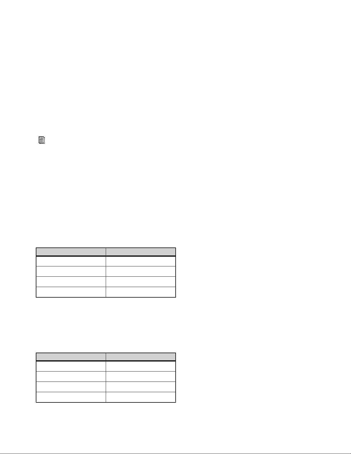
Selected Monitor Set Color
Main (A) Green
Alt 1 (B) Yellow
Att 2 (C) Amber
Monitor output muted Red
Selected Headphone Output Color
HP 1 Cyan
HP 2 Blue
HP 3 Violet
HP 4 Fuchsia

Pro Tools | Carbon Front Panel Operation
14
24 DIM button — Press to dim (attenuate) the signal level of the selected monitor set by the amount (in dB) configured in the Pro Tools
Hardware Setup (see
Main Page). The default Dim value is –15 dB. When enabled, the button lights amber. When disabled, the button
lights white.
DIM does not apply to Headphone outputs.
25 Headphone outputs 1–4 (stereo 1/4-inch).
Configuring Inputs
You can select the input (microphone, line, or instrument) and configure the input settings for channels 1–8 (front panel instrument in-
puts or back panel mic/line inputs) on the front panel of Carbon.
To select the input source for any analog input channel:
1 Press the Input Encoder (7) to cycle though and select any of input channels 1–8 as the source.
2 Press the INPT button (10) to select MIC (back panel), LINE (back panel), or INST (front panel, input channels 1–2 only) for the se-
lected channel.
To adjust the input gain for any analog input channel:
1 Press the Input Encoder (7) to cycle though input channels 1–8 and select the desired channel you want to adjust.
2 Turn the encoder (7) to boost or attenuate the input gain for the selected channel.
To link (or unlink) input channels:
1 Press the Input Encoder (7) to cycle though input channels 1–8 and select one of the channels you want in the linked pair. Input chan-
nels can only be linked in adjacent odd and even pairs (1 and 2, 3 and 4, 5 and 6, or 7 and 8).
2 Press the LINK button (9) so that it is lit (linked) or so that it is unlit (unlinked).
The selected input channel and its neighbor are linked. For example, if you selected input channel 3, channels 3 and 4 are linked; or if
you selected input channel 8, channels 7 and 8 are linked.
To select the impedance for Instrument input channels 1–2:
1 Press the Input Encoder (7) to cycle though and select input channel 1 or 2.
2 Ensure that the selected input channel is set to INST.
3 Press the Z button (11) to cycle through and select the desired impedance for the selected channel.
To select the impedance for the selected MIC input channel (channels 5–8 only):
1 Press the Input Encoder (7) to cycle though and select an input channel (5–8 only).
2 Ensure that the selected input channel is set to MIC.
3 Press the Z button (11) to cycle through and select the desired impedance for the selected channel.
To switch polarity for the selected input channel (1–8):
1 Press the Input Encoder (7) to cycle though and select an input channel.
2 Press the Ø button (12) to toggle polarity for the selected channel.
To enable phantom power for the selected input channel:
1 Press the Input Encoder (7) to cycle though and select an input channel.
2 Ensure that the selected input channel is set to MIC and that an XLR cable is plugged into the physical input.
3 Press the 48V button (13) to toggle phantom power on and off for the selected channel.
INST is only available if a 1/4-inch cable is connected to the corresponding INST input jack on the front panel.
It is not possible to adjust input gain for LINE inputs if the preamp gain is bypassed for that input (see
Line Input Gain).
It is expected to have higher input gain levels with higher impedance settings.

Pro Tools | Carbon Front Panel Operation
15
Device Reset
If you encounter a problem with Pro Tools | Carbon and Avid customer support advises that you reset the device, you can reset to the
default device settings or revert to the default firmware image.
Default Device Settings
If necessary, you can restore the default system settings (such as preamp gain, monitor gain, and so on).
To restore the default system settings for Pro Tools | Carbon:
1 Lower the volume on all output devices and mute your speakers.
2 Power off the unit.
3 Press and hold the Meter button while powering on the unit.
4 Hold the Meter button for 20 seconds while the device front panel is lights in the green start-up state.
5 After this, release the Meter button.
The device starts up with the default settings after the Meter button is released.
Default Firmware Image
To reset Pro Tools | Carbon to its default firmware image:
1 Lower the volume on all output devices and mute your speakers.
2 Power off the unit.
3 Press and hold the DIM button while powering on the unit. The default firmware will be installed. During this time the device front
panel may not provide any feedback. This process can take up to three minutes. Continue to hold the DIM button until the device re-
boots itself.
4 Once the device reboots itself, the default firmware installation process is complete. Launch Pro Tools to update the firmware to the
current version.
5 Once this process is complete, launch Pro Tools to update the firmware to the current version.
Pro Tools | Carbon Back Panel Connections 16
Pro Tools | Carbon Back Panel Connections
Pro Tools | Carbon Back Panel
1 IEC power connector.
2 ADAT Out 1 and 2.
3 ADAT In 1 and 2.
4 Word Clock In and Out (BNC).
5 Footswitch — the footswitch can be used for toggling talkback on and off (see Footswitch).
6 Ethernet 1 and 2 (AVB) — Two RJ45 Ethernet ports for control and AVB.
7 Main Monitor Out L and R (TRS balanced 1/4-inch).
8 Line In 1–8 (DB25).
9 Line Out 1–8 (DB25).
10 Mic/Line Inputs 1–8 (combined XLR/TRS 1/4-inch).
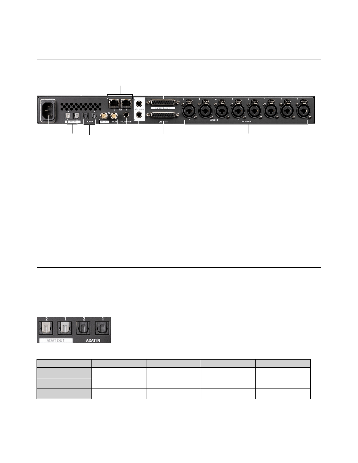
Digital I/O Connections
Optical ADAT
Pro Tools | Carbon provides two pairs of optical ADAT in and out ports for a total of 16 channels of I/O at 44.1/48 kHz, 8 channels
at 88.2/96 kHz, and 4 channels at 176.4/192 kHz. Audio channels are split across both ADAT ports at all sample rates.
Pro Tools | Carbon back panel
ADAT channel routing by port at different sample rates
Sample Rate ADAT Port 1 In ADAT Port 2 In ADAT Port 1 Out ADAT Port 2 Out
44.1/48 kHz 1–8 9–16 1–8 9–16
88.2/96 kHz 1–4 5–8 1–4 5–8
176.4/192 kHz 1–2 3–4 1–2 3–4
53
4
1
6
8
9
10
2 7
Pro Tools | Carbon Back Panel Connections 17
Analog I/O Connections
Monitor L–R Outputs
The Monitor L–R outputs on the back panel are independent of Line Out 1–8 (DB25). Use 1/4-inch TRS (balanced) or 1/4-inch TS
(unbalanced) cables to connect these line level outputs to loudspeakers for stereo monitoring. These outputs can be configured to
operate at +4 dBu or –10 dBV, and have a maximum operating level of +24 dBu.
Mic/Line Inputs XLR/TRS Combo Jacks 1–8
Both the XLR/TRS combo jacks and DB25 inputs can be used for simultaneous connection of mic and line cables to the same input
channel. This allows mic and line inputs to be switched without cable re-patching. 1/4-inch connections to the combo jacks always
use the Line input, while XLR connections always use the Mic input. If a 1/4-inch connection is made to a combo jack, that con-
nection takes precedence over the DB25 connection for that channel input.
The preamp gain on Line inputs 1–8 can be bypassed on a channel-by-channel basis in the Pro Tools Hardware Setup (see
Line I/O
Page
).
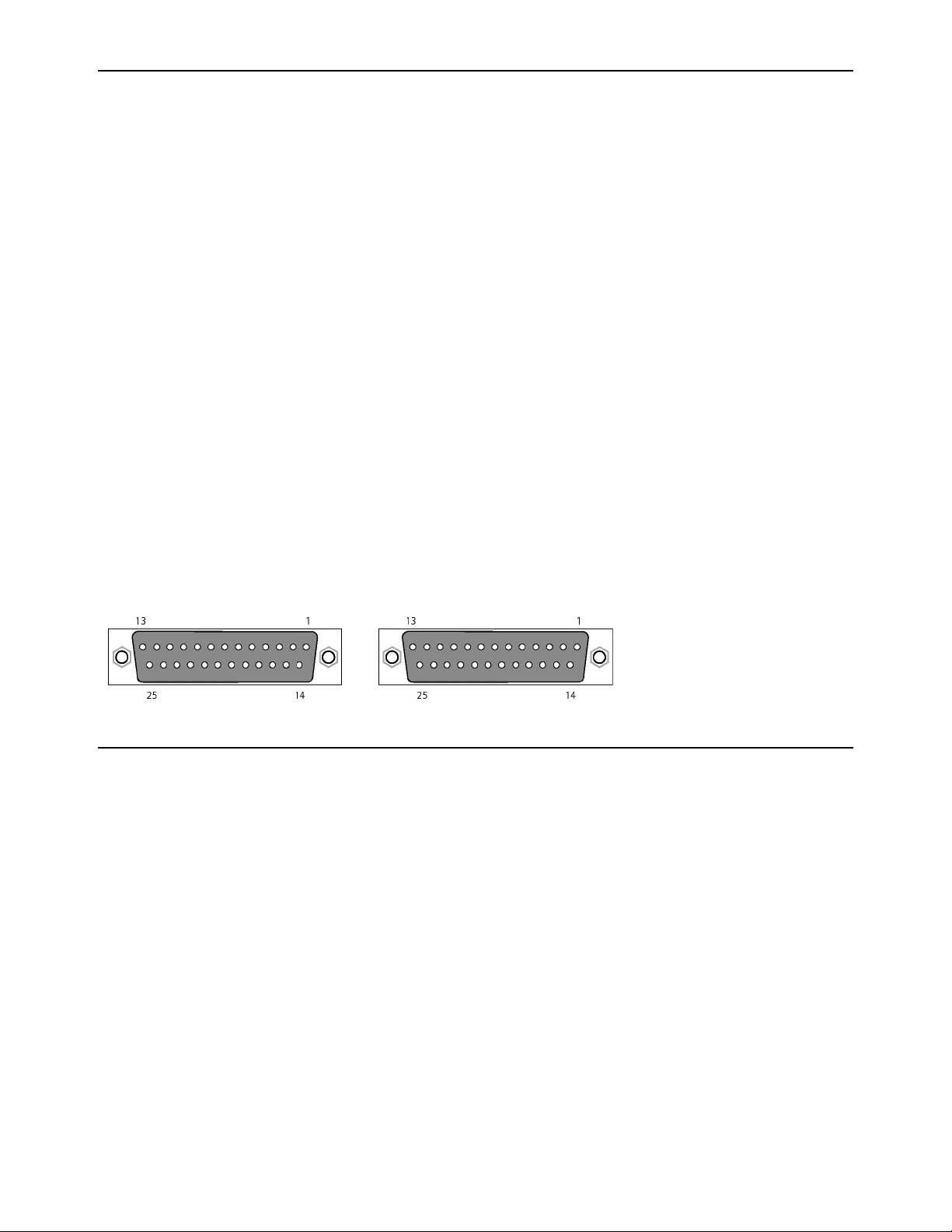
Analog I/O 25-pin D-sub Connectors
Pro Tools | Carbon uses 25-pin D-sub connectors on the back panel for both analog line input (channels 1–8) and analog line output
(channels 1–8).
The DB25 line inputs 1–8 are normalled to the TRS combo jacks. If a DB25 line input is active and a 1/4-inch cable is plugged into
the combo jack for the same input channel, the DB25 input is disconnected and the combo jack input is used instead.
The DB25 outputs can be configured to operate at +4 dBu or –10 dBV, and have a maximum operating level of +24 dBu (see
Line
I/O Page).
Footswitch
A latching or momentary footswitch can be connected to the back of Pro Tools | Carbon and can be used to engage or disengage
Talkback. Both momentary/latching and normally open/normally closed footswitches are supported. Footswitch polarity is auto-
matically detected when Pro Tools | Carbon is powered on.
8-channel Analog In 8-channel Analog Out

Configuring Pro Tools 18
Configuring Pro Tools
Once you have made the necessary cable connections for your studio and have enabled Pro Tools | Carbon for AVB in AMS, launch
and configure Pro Tools:
1 Launch Pro Tools. If the Dashboard appears, click Cancel to proceed without opening or creating a session.
2 Select Pro Tools | Carbon as the Playback Engine (Setup > Playback Engine). You may be prompted to quit and relaunch Pro
Tools to use Pro Tools | Carbon.
3 Configure Pro Tools | Carbon in the Hardware Setup (Setup > Hardware).
4 Configure the I/O Setup for use with Pro Tools | Carbon (Setup > I/O).
Playback Engine
To select Pro Tools | Carbon as the Playback Engine for Pro Tools:
1 Launch Pro Tools if it is not already running.
2 Choose Setup > Playback Engine.
3 Select Pro Tools | Carbon as the Playback Engine.
4 Configure the rest of the Playback Engine dialog as desired.
5 Click OK.
Playback Engine dialog
For most installations, the default settings are recommended. You can optimize performance later by returning to the Play-
back Engine dialog.
To open the Playback Engine dialog when launching Pro Tools, press and hold the N key.
Configuring Pro Tools 19
Hardware Setup
When Pro Tools | Carbon is connected to your Pro Tools system, the Hardware Setup provides two pages specifically for setting
up Pro Tools | Carbon.
To configure Pro Tools | Carbon in the Hardware Setup dialog:
1 Launch Pro Tools if it is not already running.
2 Choose Setup > Hardware.
3 Configure the settings for Pro Tools | Carbon, which are described in detail below.
4 Click OK when you are done to close the Hardware Setup dialog.
Hardware Setup, Pro Tools | Carbon
When a monitor set is enabled, the audio signal from the respective physical outputs is attenuated. When a monitor set is not
enabled, the audio signal from the respective physical outputs is not attenuated. This is indicated in the Hardware Setup by
a “!” to the right of the monitor set icon. Do not connect speakers to physical outputs where a monitor set is not enabled. Do-
ing so will result in a very loud, unattenuated output level.
Configuring Pro Tools 20
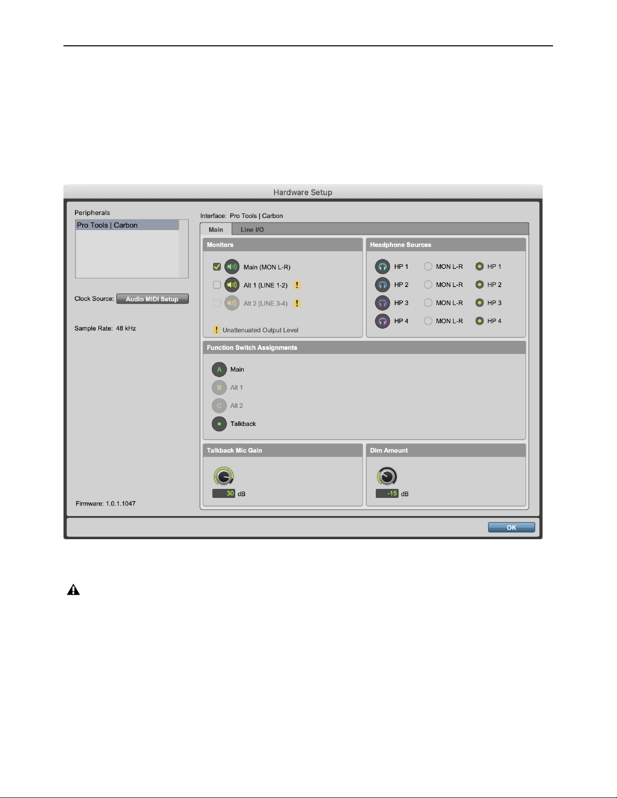
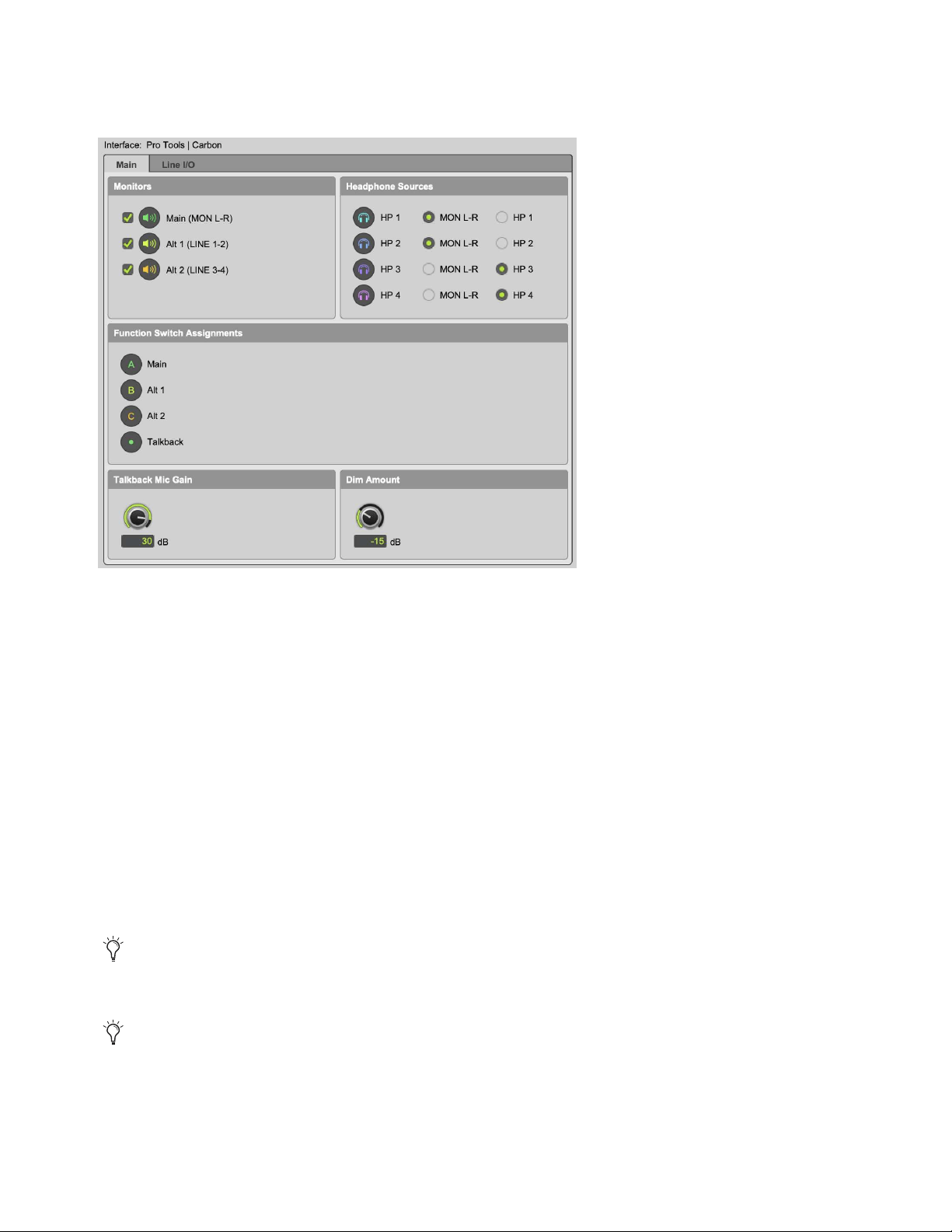
Main Page
Click the Main tab in the Hardware Setup to view the Main page.
Monitors
The Monitors section lets you enable or disable the following Monitor options:
Main (MON L–R)
When enabled, the Main monitor set can be selected for monitoring on the front panel of Pro Tools | Carbon. The
Main monitor uses the Monitor L–R outputs on the back panel.
Alt 1 (LINE 1–2)
When enabled, the Alt 1 monitor set can be selected for monitoring on the front panel of Pro Tools | Carbon. Alt
1 uses channels 1 and 2 of the DB25 line outputs on the back panel.
Alt 2 (LINE 3–4)
When enabled, the Alt 2 monitor set can be selected for monitoring on the front panel of Pro Tools | Carbon. Alt
2 uses channels 3 and 4 of the DB25 line outputs on the back panel.
Headphone Sources
The Headphone Sources section lets you select the source for each of the four headphone outputs on the front panel of
Pro Tools | Carbon.
MON L–R
When this option is selected, the corresponding headphone output mirrors the signal of the currently selected Monitor
set. If no Monitor set is enabled, the headphone output mirrors the signal of the MON L–R outputs on the back panel.
HP 1–4
When a source is set to a headphone output (HP 1–4), any Pro Tools track (or other Core Audio software audio channel)
that is routed to that Headphone output passes audio to that Headphone output.
Hardware Setup, Pro Tools | Carbon Main page
This is useful when you want the listener to hear the same audio material as the main mix in both Pro Tools and Core Audio output.
This is useful when you want the listener to hear different audio material from the main mix in Pro Tools and Core Audio output,
such as for a unique cue mix.
Configuring Pro Tools 21
Function Switch Assignments
The Function Switch Assignments section shows whether or not the control assignments for the front panel buttons are enabled.
If a control assignment is not available, such as if Alt 2 (3–4) is disabled, the button on the front panel is unlit and the corresponding
icon in the Hardware Setup is grayed out.
Talkback Mic Gain
Adjust the knob or type a value (in dB) to set the talkback mic gain for when Talkback is engaged. Talkback mic gain can be set
to the following fixed values: 0, 6, 12, 18, 24, 30, or 36 dB. It defaults to 30 dB.
Dim Amount
Adjust the knob or type a value (in dB) to set the Dim level for when the DIM button is pressed on the front panel or when Talkback
is engaged.
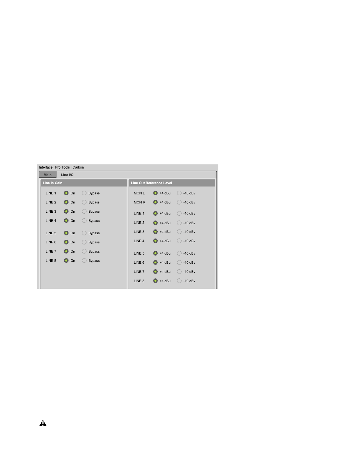
Line I/O Page
Click the Line I/O tab in the Hardware Setup to view the Line I/O page. You can set whether each of the Line input channels bypass
input gain control. You can also set the reference level (+4 dBu or –10 dBV) for each of the analog outputs.
Line Input Gain
Select On to apply input gain control to the corresponding Line input (either XLR/TRS or DB25 inputs). Select Bypass to bypass
the input preamp for the corresponding Line input channel. Enable Bypass when connecting an external preamp or line-level
source, and the most transparent signal path is desired. For any linked input pairs, the Line In Gain setting is linked.
Line Output Reference Level
Select either +4 dBu or –10 dBV as the reference level for each analog output: MON L–R (TRS outputs) and LINE 1–8 (DB25 out-
puts). When connecting balanced audio gear, use +4 dBu. When connecting unbalanced audio gear, use –10 dBV.
Sample Rate
The Sample Rate indicator displays the current sample rate of the session for reference. The interface sample rate is determined
by Pro Tools or Core Audio. When Pro Tools is running, the sample rate is set by Pro Tools. When Pro Tools is closed, the sample
rate for Pro Tools | Carbon can be set in AMS. Pro Tools and third-party Core Audio applications cannot use different sample rates
for Pro Tools | Carbon at the same time. The default sample rate for Pro Tools | Carbon is 48 kHz.
Hardware Setup, Line I/O page
Do not attempt to change the device sample rate using AMS or a third-party Core Audio application while Pro Tools is running.
Configuring Pro Tools 22
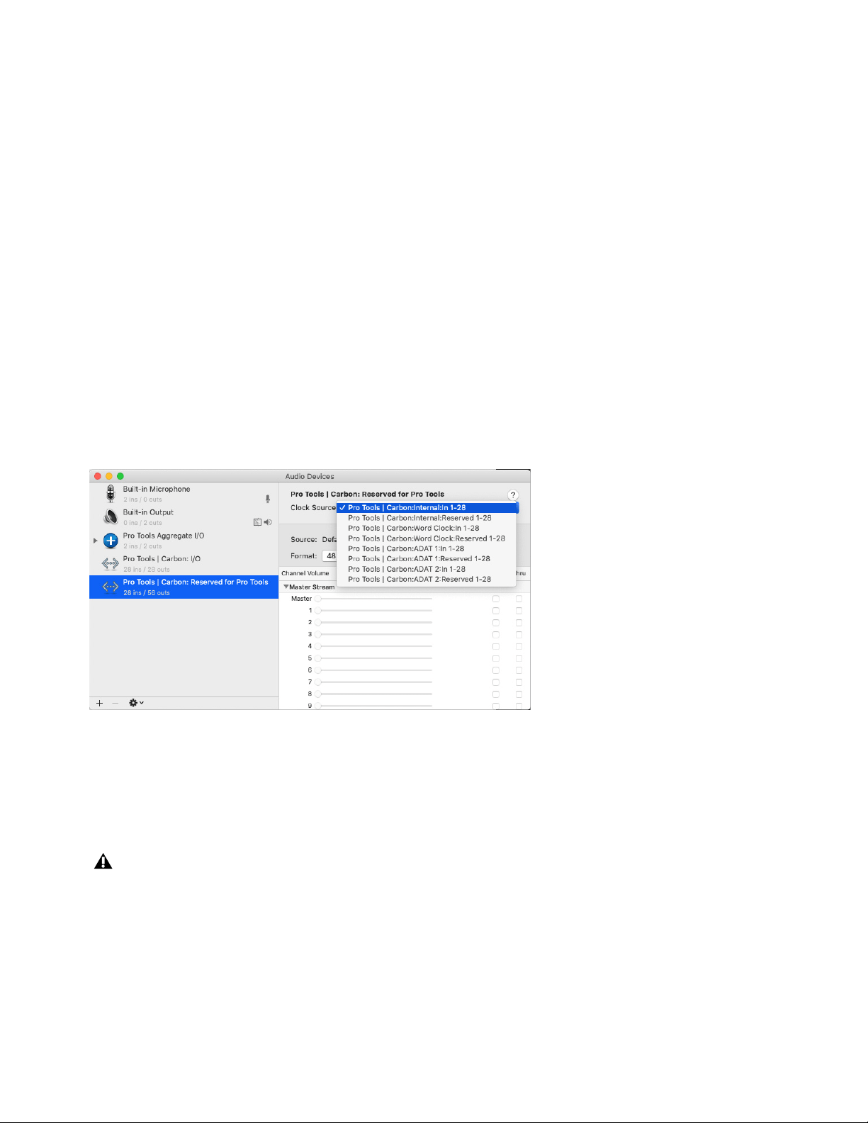
Clock Source
You can set the Clock Source for Pro Tools | Carbon in the Audio window of AMS, which can be accessed from the Hardware
Setup dialog. The Clock Source defaults to the internal clock. If other digital devices are connected to Pro Tools | Carbon that can
be set to follow the internal clock of Pro Tools | Carbon, you can leave Pro Tools | Carbon set to the default Internal option. How-
ever, if you need Pro Tools | Carbon to follow an external clock source, such as a connected synchronization peripheral that gen-
erates Word Clock or a digital device that sends clock over ADAT optical, you will need to set Pro Tools | Carbon to follow that
clock source.
To select the appropriate Clock Source for Pro Tools | Carbon:
1 Do one of the following:
• In macOS, launch AMS.
• In Pro Tools, choose
Setup > Hardware and click Audio MIDI Setup.
2 Choose Window > Show Audio Devices.
3 Select Pro Tools | Carbon: Reserved for Pro Tools in the Audio Device list.
4 From the Clock Source selector, select the clock source that Pro Tools | Carbon should follow:
• Internal (default)
• Word Clock
• ADAT 1
• ADAT 2
Each possible internal and external Clock Source is listed once for each AVB input stream in the current Pro Tools | Carbon AVB
configuration. There is no functional difference between the listed options for each individual internal or external Clock Source.
Ensure that
Internal is selected if you are not clocking to an external source. If you need to clock to an external source, ensure that
the proper cable connections are robust and that the external clock source is providing clock data at the appropriate sample rate,
then select the Clock Source that matches your system configuration.
Selecting the Clock Source for Pro Tools | Carbon in AMS
If Pro Tools | Carbon loses sync with the selected external clock, the selected external clock is not automatically recovered once
it becomes valid again. If EXT starts flashing on the front panel of Pro Tools | Carbon, first select the Internal clock source for
Pro Tools | Carbon in AMS, next fix the clocking error and ensure that the external clock signal is valid, then re-select the ap-
propriate external clock source in AMS and verify that EXT lights solid green.
Configuring Pro Tools 23
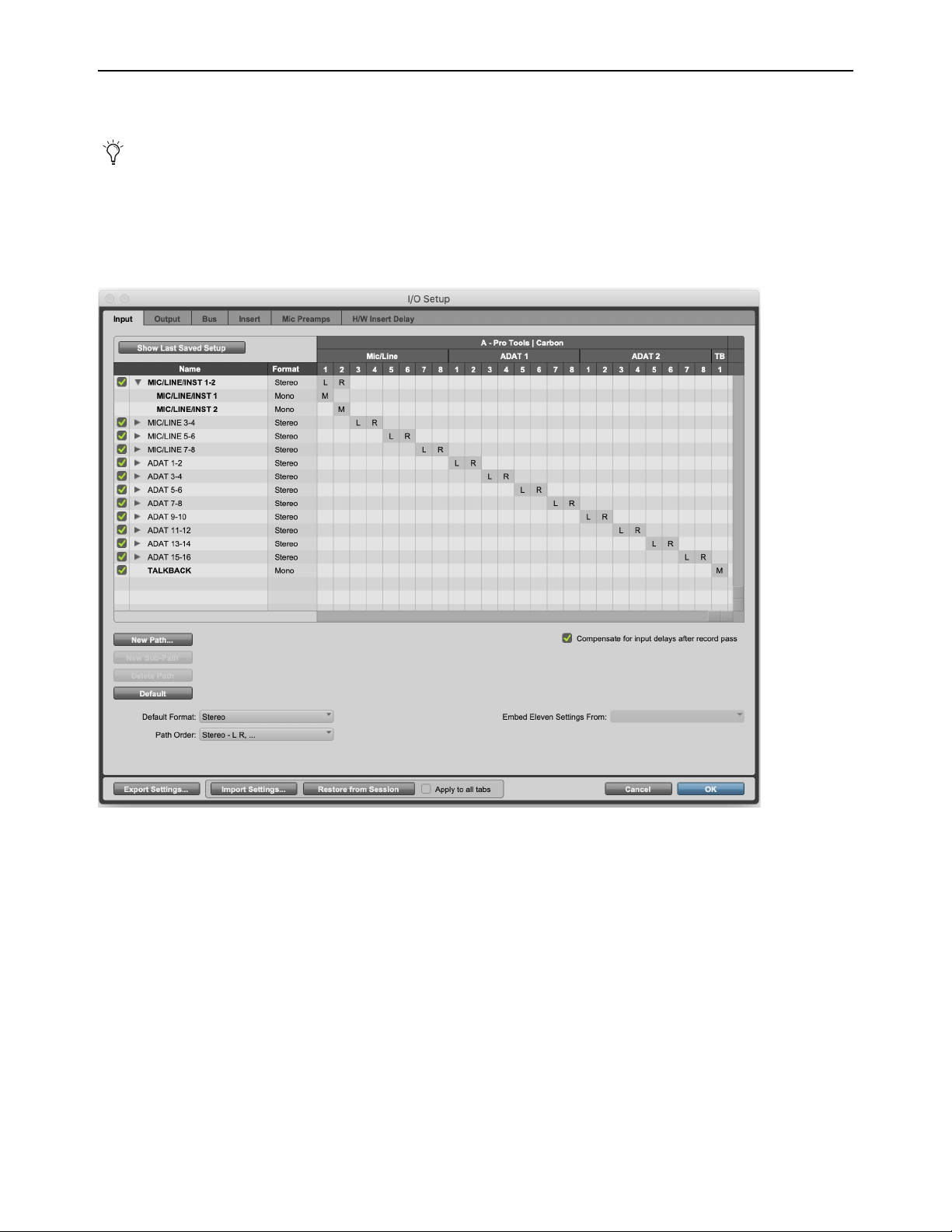
I/O Setup
Configure the Pro Tools I/O Setup for input and output routing for Pro Tools | Carbon.
Pro Tools | Carbon Input Setup
Pro Tools | Carbon provides Mic, Line, Instrument, ADAT, and Talkback mic inputs.
At higher sample rates, the number of available ADAT Inputs and Outputs are reduced for each port. At 88.2/96 kHz, only
ADAT channels 1–4 are available, and at 176.4/192 kHz, only ADAT channels 1–2 are available. Unavailable ADAT chan-
nels are indicated in italic text in the Input, Output, Bus, and Insert pages of the I/O Setup.
I/O Setup, Input page (default Input configuration for Pro Tools | Carbon using the Stereo format)
Configuring Pro Tools 24
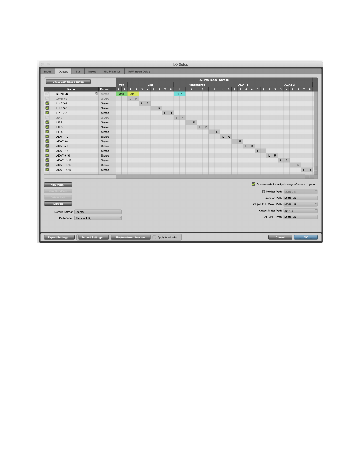
Pro Tools | Carbon Output Setup
In addition to line and ADAT outputs, Pro Tools | Carbon has a dedicated Main stereo monitor output, two additional Alternate ste-
reo monitor output paths, and four dedicated Headphone outputs.
Main and Alt Monitor Paths
The Main monitor output path and the two Alt monitor paths can be enabled or disabled in the Hardware Setup. When enabled, each
appears color coded in the Output page of the I/O Setup. Each stereo monitor path has a fixed output assignment:
Main
The Main monitor path is always assigned to the 1/4-inch TRS stereo monitor outputs.
Alt 1
The Alt 1 monitor path is always assigned to the DB25 line outputs 1–2.
Alt 2
The Alt 2 monitor path is always assigned to the DB25 line outputs 3–4.
Headphone Outputs
Each Headphone output can be assigned to either mirror the Main monitor path or use its own dedicated path.
AFL/PFL Path and Pro Tools | Carbon
The AFL/PFL Path is used only for AFL and PFL Solo Modes. If you do not intend to use Pro Tools AFL and PFL Solo Mode fea-
tures, disable the AFL/PFL Path to make more system resources available for other audio routing and processing tasks.
I/O Setup, Output page
DSP Mode for Low-Latency Monitoring 25
DSP Mode for Low-Latency Monitoring
DSP Mode ensures that low-latency monitoring is maintained during recording with Pro Tools | Carbon. You can enable or disable
DSP Mode on a track-by-track basis. DSP Mode can be enabled for Audio, Auxiliary Input, Instrument, Routing Folder, and Master
Fader tracks. For tracks with DSP Mode enabled, all plug-ins on the track switch from Native to DSP (if a DSP version is available),
and all track inputs and outputs, including sends, run on the HDX DSP mixer in Pro Tools | Carbon itself. To ensure the lowest pos-
sible latency for monitoring, DSP and Native plug-ins cannot be active on the same track while DSP Mode is enabled. Any Na-
tive-only plug-ins are automatically bypassed in DSP Mode.
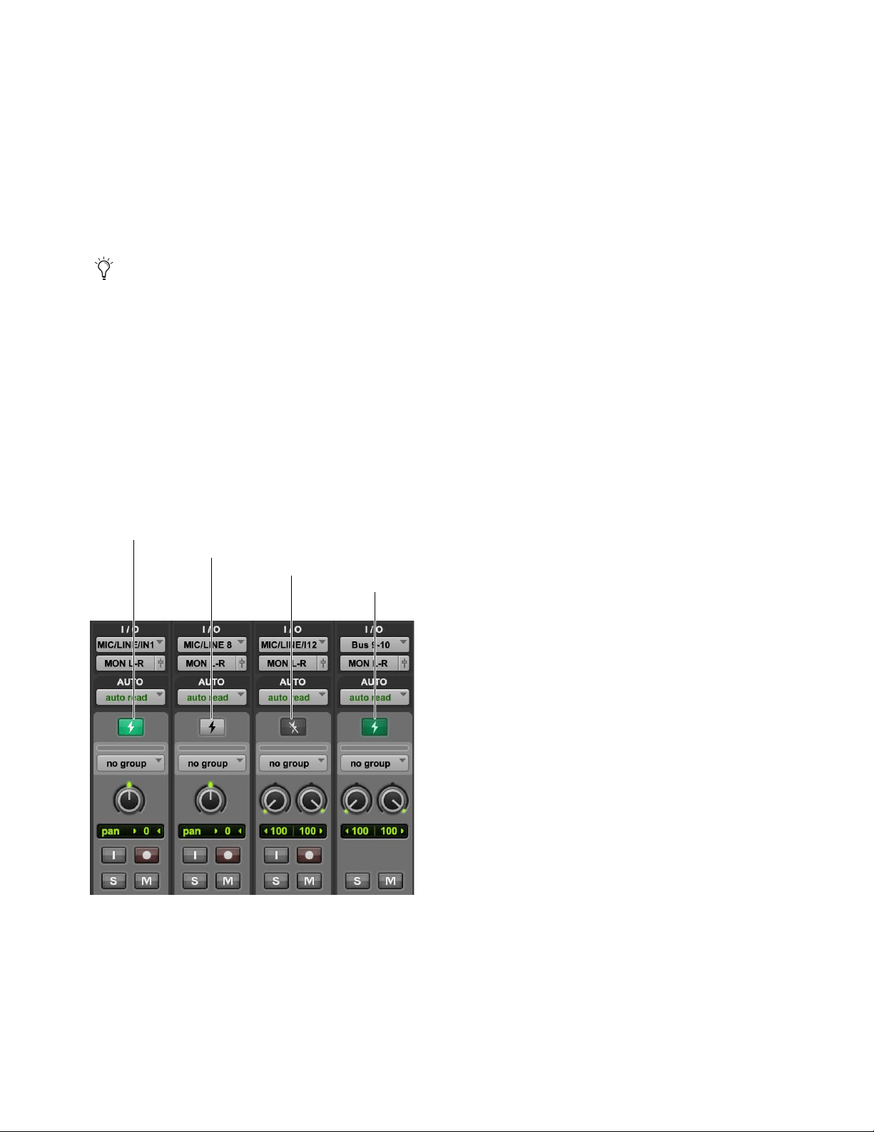
The following DSP Mode states are possible, as indicated by the DSP Mode icon:
Native Mode (DSP Mode Disabled)
When DSP Mode is disabled on a track it is in Native Mode and the DSP Mode button is gray.
All plug-ins on the track are Native only.
DSP Mode Enabled
When DSP Mode is enabled on a track, the DSP Mode button turns bright green. All Native plug-ins with DSP
versions switch to DSP while Native only plug-ins are bypassed. The entire signal path for the track runs on the DSP mixer in
Pro Tools | Carbon.
DSP Mode Auto Enabled
If any track is part of the signal chain of another track that is set to DSP Mode, it is automatically set to
DSP Mode. When DSP Mode is automatically enabled on a track, the DSP Mode button turns dim green.
DSP Mode Safe
When DSP Mode Safe is enabled on a track, DSP Mode will not be automatically enabled on that track.
You can also use DSP Mode on audio tracks that are not record-armed or input-enabled if you want to offload Native processing
on the host CPU to HDX DSP processing on Pro Tools | Carbon when mixing.
DSP Mode button states
DSP Mode Auto enabled
DSP Mode Safe enabled
Native Mode
DSP Mode enabled
DSP Mode for Low-Latency Monitoring 26
Enabling DSP Mode
Enable DSP Mode on tracks for low-latency monitoring during recording or input monitoring. With DSP Mode enabled:
Protecting low latency is the highest priority.
The track and its entire signal chain run on the HDX DSP in Pro Tools | Carbon.
Any plug-ins on the track that are not available in DSP format are bypassed.
HEAT is not supported on audio tracks in DSP Mode. In the Mix window, HEAT is bypassed for all audio tracks in DSP Mode.
To enable DSP Mode on a track, do one of the following:
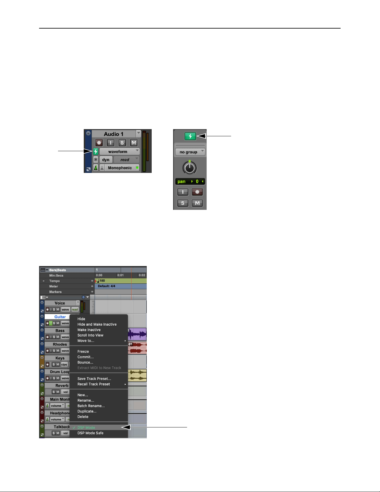
In the Mix or Edit window, click the DSP Mode button on the track so that it lights bright green.
In the Mix or Edit window, right-click the DSP Mode button on the track and select DSP Mode.
Right-click the Track name in the Track List, or in the Edit or Mix window, and select DSP Mode. The DSP Mode button is not
shown when the Track Height is set to Small, Mini, or Micro in the Edit window. In this case, use this method to enable (or dis-
able) DSP Mode, or do so in the Mix window.
Track DSP Mode button enabled: in the Edit window (left) and in the Mix window (right)
Right-click a track name to enable DSP Mode in the Edit window
DSP Mode for Low-Latency Monitoring 27
Enabling DSP Mode Safe
Use DSP Mode Safe to prevent DSP Mode from being automatically enabled on a track. This is useful if you want to route any
audio from a DSP Mode–enabled track with any plug-ins that are only available in Native format. For example, you might want to
send audio from a DSP Mode–enabled audio track to a DSP Mode Safe–enabled Auxiliary Input track for processing with a reverb
plug-in that is only available as a Native plug-in. DSP Safe Mode can also be useful if you just need to avoid using DSP for plug-ins
on a track for any reason.
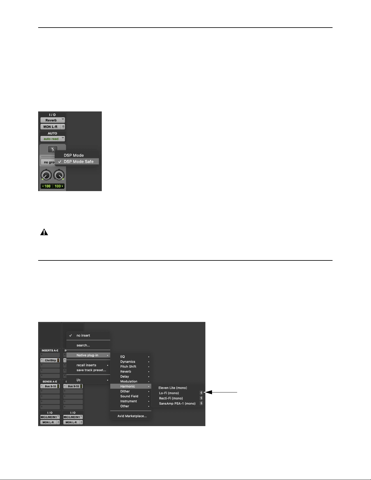
To enable DSP Mode Safe on a track, do one of the following:
Right-click the Track name in the Track List, or in the Edit or Mix window, and select DSP Mode Safe.
In the Mix or Edit window, right-click the DSP Mode button on the track and select DSP Mode Safe.
In the Mix or Edit window, Command-click the DSP Mode button on the track.
Indicators for DSP Plug-ins, Inserts, Sends, and Outputs
DSP-Compatible Badge for Plug-ins
For plug-ins that are available in both Native and DSP formats, the DSP-Compatible Badge appears to the right of plug-in name
in the Plug-in Insert selector. Plug-ins without this badge are only available in Native format and, if inserted on a track, are auto-
matically bypassed when DSP Mode is enabled on that track.
Enabling DSP Mode Safe on a track in the Mix window
Tracks in DSP Mode provide ultra-low-latency monitoring, whereas tracks in Native Mode introduce latency when monitoring
live inputs. Consequently, live audio monitored both through tracks in DSP Mode and tracks in Native Mode (including DSP
Mode Safe-enabled tracks) may not be aligned.
DSP-Compatible Badge
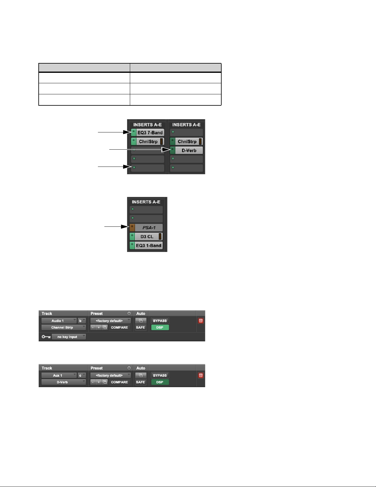
DSP Mode for Low-Latency Monitoring 28
DSP Mode Insert Indicator
Plug-in Insert selectors change color to indicate whether DSP plug-ins are inserted on a track that is DSP Mode enabled or DSP
Mode auto-enabled, or if a plug-in has been made inactive due to insufficient DSP resources.
Plug-in Format Indicator in Plug-in Windows
The Plug-in Format indicator is color coded to indicate whether DSP plug-ins are inserted on a track that is DSP Mode–enabled or
DSP Mode–auto enabled, or if a plug-in has been made inactive due to insufficient DSP resources. Similarly, with Dynamics
plug-ins, the Key Input selector turns dark orange to indicate that there are insufficient DSP resources.
DSP Mode Insert indicator color coding
DSP Mode Color
Enabled Green
Auto-enabled Dark Green
Inactive due to insufficient resources Dark Orange
Insert DSP Mode indicators
DSP Mode enabled
DSP Mode automatically enabled
Insert Selector dot
DSP Mode enabled
DSP Mode enabled
DSP Mode auto-enabled
DSP Mode enabled,
plug-in inactive due to
insufficient resources
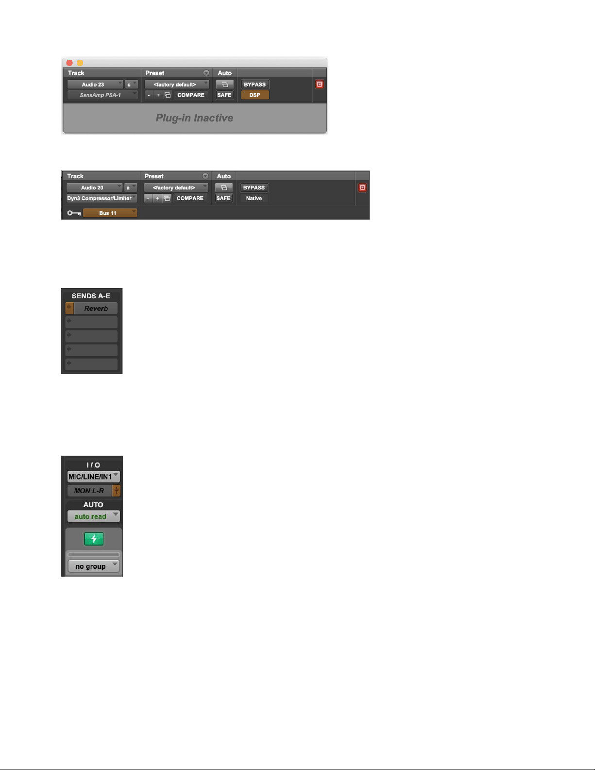
DSP Mode for Low-Latency Monitoring 29
Send Selector DSP Mode Indicator
When a Send is made inactive due to insufficient DSP resources, the Send selector appears dark orange and any text is italicized.
Output View Selector DSP Mode Indicator
When a track output is made inactive due to insufficient DSP resources, the Output View selector appears dark orange and any text
is italicized.
DSP Mode, DSP plug-in inactive due to insufficient DSP resources
DSP Mode, Key Input inactive due to insufficient DSP resources
DSP Mode-enabled, send inactive due to insufficient resources
DSP Mode-enabled, track output inactive due to insufficient resources
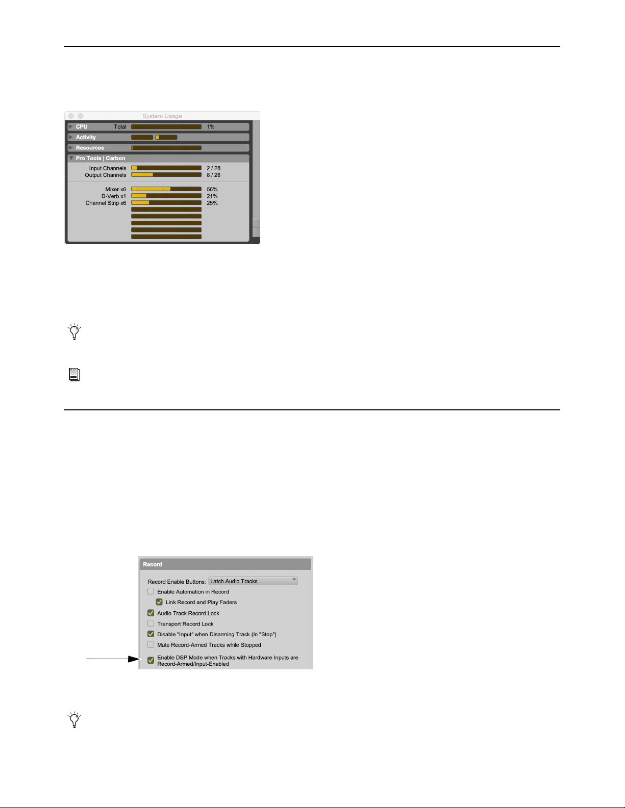
DSP Mode for Low-Latency Monitoring 30
System Usage
The System Usage window in Pro Tools provides a Pro Tools | Carbon pane that lets you monitor the number of available AVB In-
put and Output channels in use, and how much DSP is being used by plug-ins and the mixer.
Input Channels
Shows the number of AVB channels dedicated to audio streams from Pro Tools | Carbon to Pro Tools.
Output Channels
Shows the number of AVB channels dedicated to audio streams from Pro Tools to Pro Tools | Carbon.
DSP Meters
Show how much of the 8 HDX DSPs on Pro Tools | Carbon are being used by the mixer and DSP plug-ins.
Enable DSP Mode Preference
The Enable DSP Mode when Tracks with Hardware Inputs are Record-Armed Input-Enabled preference automatically sets au-
dio tracks to DSP Mode when they are record-armed or input-enabled. This ensures low-latency monitoring using DSP Mode for
all live signal paths. This option is enabled by default.
To enable (or disable) DSP Mode automatically on audio tracks that are enabled for Input Monitoring or recording:
1 Choose Setup > Preferences > Operation.
2 In the Record section, select (or deselect) the Enable DSP Mode when Tracks with Hardware Inputs are Record-Armed/
Input-Enabled option.
3 Click OK.
System Usage window, Pro Tools | Carbon pane
Pro Tools reserves certain channels for internal communication. As a result, the number of Output Channels shown in the Sys-
tem Usage window is always two fewer than the number of channels shown in AMS.
A larger or smaller AVB configuration can be selected in AMS to suit your input and output channel requirements. For more
information, see
AVB Device Configuration in AMS.
Enable DSP Mode when Tracks with Hardware Inputs are Record-Armed/ Input-Enabled option selected
Any track that is automatically DSP Mode-enabled due to this preference remains DSP Mode-enabled until it is manually set to
Native Mode.
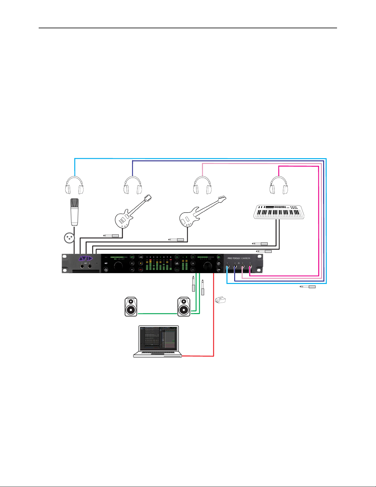
DSP Mode for Low-Latency Monitoring 31
Workflow Example: Recording in DSP Mode for Low-Latency Monitoring
The following workflow example uses DSP Mode for recording a singer with DSP plug-in processing and low-latency monitoring.
This example session is made up of the following tracks (see the graphic on the next page):
• 3 mono audio tracks for vocals, guitar, and bass. Each track has EQ and dynamics plug-ins, and the vocal track also has a
slap-back delay.
• 2 stereo audio tracks, one for electric piano and another for drum loops. Each track has EQ and dynamics plug-ins.
• 1 stereo Auxiliary Input track for reverb processing.
• 2 Master Fader tracks, one for control room monitoring and the other for the singer’s headphones. Each has a limiter on it.
• 1 mono Auxiliary Input track for the built-in talkback mic.
The following diagram shows the physical studio connections for this workflow example. While this workflow example only re-
views recording vocals in DSP Mode with a dedicated headphone mix, you can just as easily have independent headphone mixes
for the rest of the band.
Physical studio connections

DSP Mode for Low-Latency Monitoring 32
Adjust the Mix for Recording
Start playback to set the levels and panning of the instruments to get the mix you want in the control room monitors. Set the send
levels from each track to balance the headphone mix. Input-enable the vocal track and use the talkback mic to communicate with
the singer and adjust the headphone mix to the singer’s liking. Once the singer is happy with the headphone mix, you are ready to
record some vocals.
Session with the band already recorded
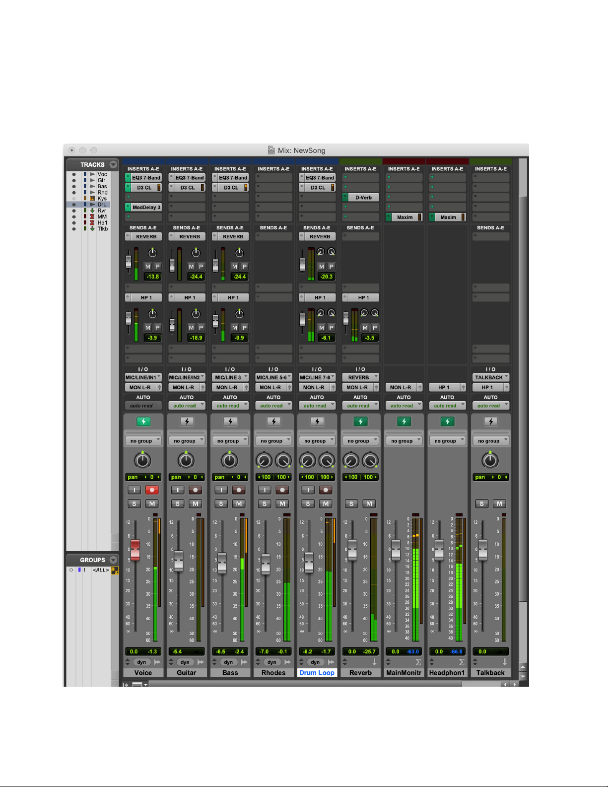
DSP Mode for Low-Latency Monitoring 33
Record with Low-Latency Monitoring
Enable DSP Mode on the vocal track. Notice that all tracks that are part of the signal chain for the vocal track have DSP Mode en-
abled automatically: the reverb Auxiliary Input track and both Master Fader tracks. All plug-ins on these tracks switch from Native
to DSP format (any Native only plug-ins on any of these tracks are automatically bypassed).
Record-arm the vocal track, and when the singer is ready, start recording. The singer will hear themselves in the mix with virtually
no latency.
Recording vocals in DSP Mode for low-latency monitoring
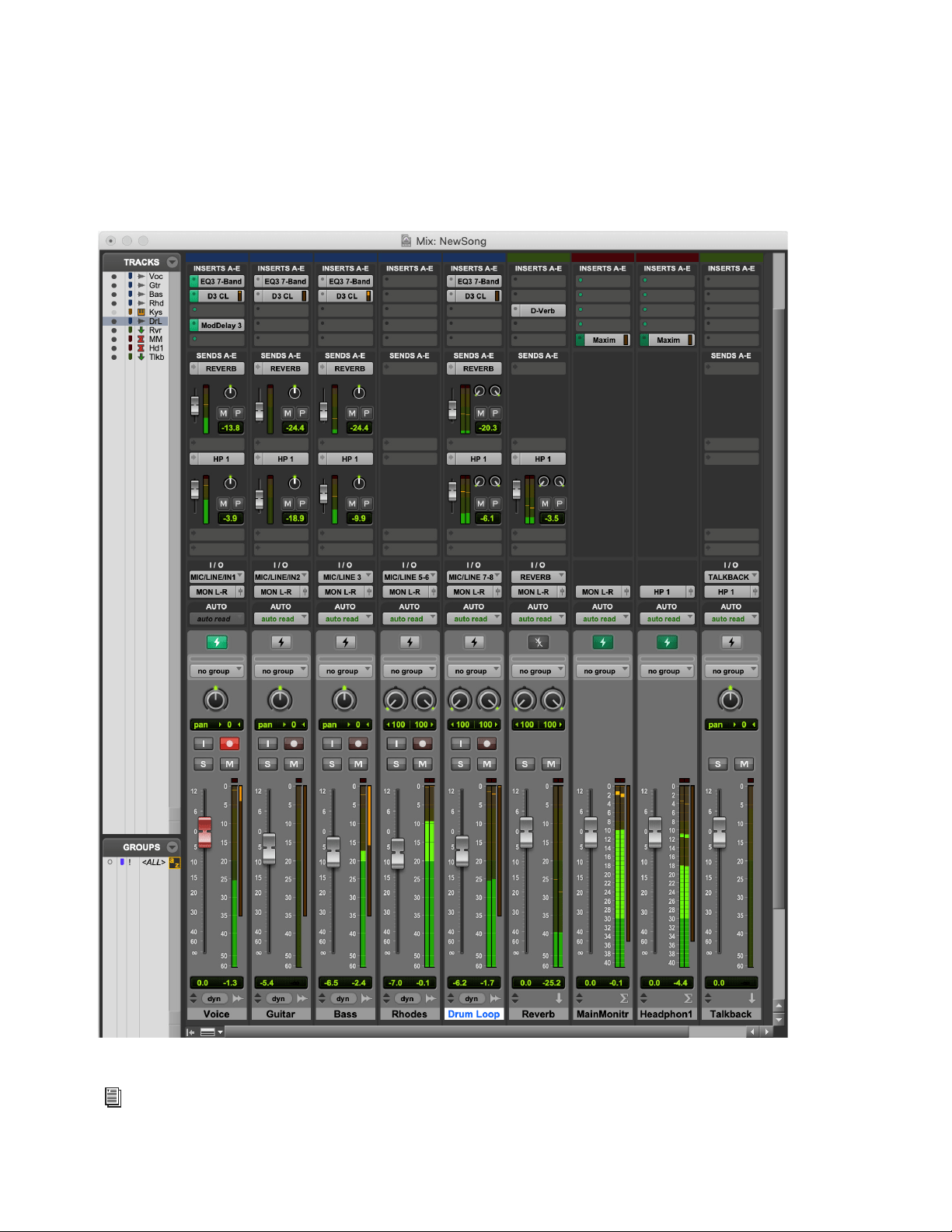
DSP Mode for Low-Latency Monitoring 34
Use DSP Mode Safe to Record with Native Reverb
Let’s assume that you have a Native-only reverb plug-in that you really like. You can still record vocals with virtually no latency
in their monitor mix while still using your favorite Native-only reverb plug-in to process all of the audio tracks. Enable DSP Mode
Safe on the reverb track and set the wet/dry mix on the reverb plug-in to 100% wet. Enable DSP Mode on the vocal track—DSP
Mode is enabled for all tracks in the signal chain of the vocal track except for the reverb track. Record-arm the vocal track and when
the singer is ready, start recording. There will be latency on the reverb track, but given the nature of reverb processing it won’t re-
ally be noticeable. The important thing is that the talent won’t hear any latency in the mix with their performance.
Session configured for recording vocals, but with Auxiliary Input track in DSP Mode Safe for Native reverb processing
For complete information about recording and mixing in Pro Tools, refer to the Pro Tools Reference Guide, which can be
accessed from the Help menu in Pro Tools.

DSP Mode for Low-Latency Monitoring 35
Tips for Using DSP Mode
To ensure optimal workflows in DSP Mode:
Use input and output gain controls on Native-only plug-in inserts to make up for any undesirable changes in signal level when
switching between Native Mode and DSP Mode.
Since DSP Mode does not reduce latency for tracks that are not part of a live signal path, avoid enabling DSP Mode on tracks
that are not part of the signal chain for recording and input monitoring. However, note that DSP Mode can be used to offload
plug-in processing from the CPU when mixing without consequence.
To avoid unnecessarily enabling DSP Mode automatically on tracks that are fed by other channels of a multi-channel bus, use
dedicated mono bus paths instead of mono sub-paths of stereo busses when routing mono audio signals with tracks in DSP
Mode. You will need to specifically create mono bus paths in I/O Setup since the default bus paths will always be stereo with
mono sub-paths.
Avoid routing unrelated signals to the channels of a multichannel bus. For example, avoid routing a guitar signal to the left chan-
nel and a bass signal to the right channel of the same stereo bus.

Appendix A: Specifications 36
Appendix A: Specifications
Audio Specifications
Microphone Preamp Inputs
Line Inputs
Back panel: XLR inputs 1–8
Frequency Response 20 Hz to 20 kHz, ±0.1 dB
Gain Range 3–60 dB in 1 dB steps
Equivalent Input Noise (EIN) –129 dBu (A-weighted)
Signal to Noise Ratio (SNR) –123.5 dB, –126 dB (A-weighted)
Dynamic Range 126 dB (A-weighted)
Total Harmonic Distortion (THD) 1 kHz @ –1 dBFS –105 dB (0.00056%)
Maximum Input Level +24 dBu
Crosstalk –145 dB @ 1 kHz
Phantom Power +48V
Connector Type 8 XLR (XLR/TRS Combo)
Back panel: DB25 inputs 1–8 and 1/4-inch TRS inputs 1–8
Frequency Response 20 Hz to 20 kHz, ±0.1 dB
Gain Range 6–60 dB in 1 dB steps
SNR –122 dB, –125 dB (A-weighted)
Dynamic Range 123 dB, 125 dB (A-weighted)
THD 1 kHz @ –1 dBFS –106 dB (0.0005%)
Maximum Input Level +24 dBu
Crosstalk –145 dB @ 1 kHz
Connector Type 1/4-inch TRS Balanced (Combo XLR/TRS)
DB25 (Tascam wiring), normalled

Appendix A: Specifications 37
Line Inputs (True Bypass)
Instrument Inputs
Line Outputs
Back panel: DB25 inputs 1–8 and 1/4-inch TRS inputs 1–8
Frequency Response 20 Hz to 20 kHz, ±0.1 dB
Gain Range 0 dB fixed
SNR –123 dB, –126 dB (A-weighted)
Dynamic Range 123 dB, 126 dB (A-weighted)
THD 1 kHz @ –1 dBFS –113 dB (0.00022%)
Maximum Input Level +24 dBu
Crosstalk –145 dB @ 1 kHz
Connector Type 1/4-inch TRS Balanced (Combo XLR/TRS)
DB25 (Tascam wiring), normalled
Front panel 1/4-inch TS inputs 1–2
Frequency Response 20 Hz to 20 kHz, ±0.1 dB
Gain Range 3–60 dB in 1 dB steps
SNR –120 dB, –122 dB (A-weighted)
Dynamic Range 123 dB, 125 dB (A-weighted)
THD 1 kHz @ –1 dBFS –103 dB (0.0007%)
Maximum Input Level +15.7 dBV
Crosstalk –145 dB @ 1 kHz
Connector Type 1/4-inch TS Unbalanced
Back panel DB25 outputs 1–8
Frequency Response 20 Hz to 20 kHz, ±0.1 dB
SNR –120 dB (A-weighted)
Dynamic Range 120 dB (A-weighted)
THD 1 kHz @ –1 dBFS –110 dB (0.0003%)
Maximum Output Level +24 dBu
Crosstalk –135 dB @ 1 kHz
Connector Type DB25 (Tascam wiring)
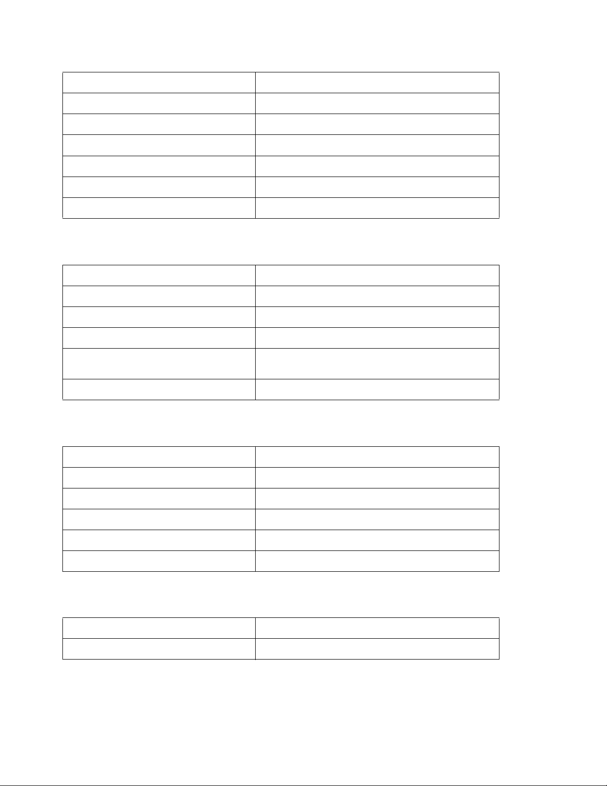
Appendix A: Specifications 38
Monitor Outputs
Headphone Outputs
Digital I/O ADAT
Synchronization
Back panel 1⁄4-inch TRS outputs L–R
Frequency Response 20 Hz to 20 kHz, ±0.1 dB
SNR –120 dB (A-weighted)
Dynamic Range 120 dB (A-weighted)
THD 1 kHz @ –1 dBFS –110 dB (0.0003%)
Maximum Output Level +24 dBu
Crosstalk –135 dB @ 1 kHz
Connector Type 1⁄4-inch TRS Balanced
Front panel 1/4-inch TRS stereo 1–4
Power 100 mW into 300 ohm; 200 mW into 32 ohm
Frequency Response 20 Hz to 20 kHz, ±0.1 dB
SNR –116 dB (A-weighted)
Dynamic Range 116 dB (A-weighted)
Total Harmonic Distortion + Noise Ratio 32 Ohm: –87 dB (0.0045%)
300 ohm: –100 dB (0.001%)
Connector Type 1⁄4-inch TRS Stereo
Back panel optical ports 1 and 2
Format ADAT Digital Lightpipe with S/MUX
Supported Sample Rates 44.1, 48, 88.2, 96, 176.4, 192 kHz
Channel Assignments (44.1–48 kHz) Port 1 = Channels 1–8, Port 2 = Channels 9–16
Channel Assignments (88.2–96 kHz) Port 1 = Channels 1–4, Port 2 = Channels 5–8
Channel Assignments (176.4/192 kHz) Port 1 = Channels 1–2, Port 2 = Channels 3–4
Connector Type Optical TOSLINK
Connector Type BNC
Synchronization Sources Internal, ADAT, Word Clock

Appendix A: Specifications 39
Network Interface
Mechanical Specifications
Environmental Specifications
Interface 1000BASE-T, RJ45 connector, 4-pair connection
Chassis standard 19”, 1 RU
Chassis depth, without connectors mounted 34.8 cm / 13.5”
Chassis body width 44.2 cm / 17.4”
Weight 5.44 kg / 12 lbs.
Operating Temperature 4–40º C / 39.2–140º F
Humidity 20–85% (non-condensing)
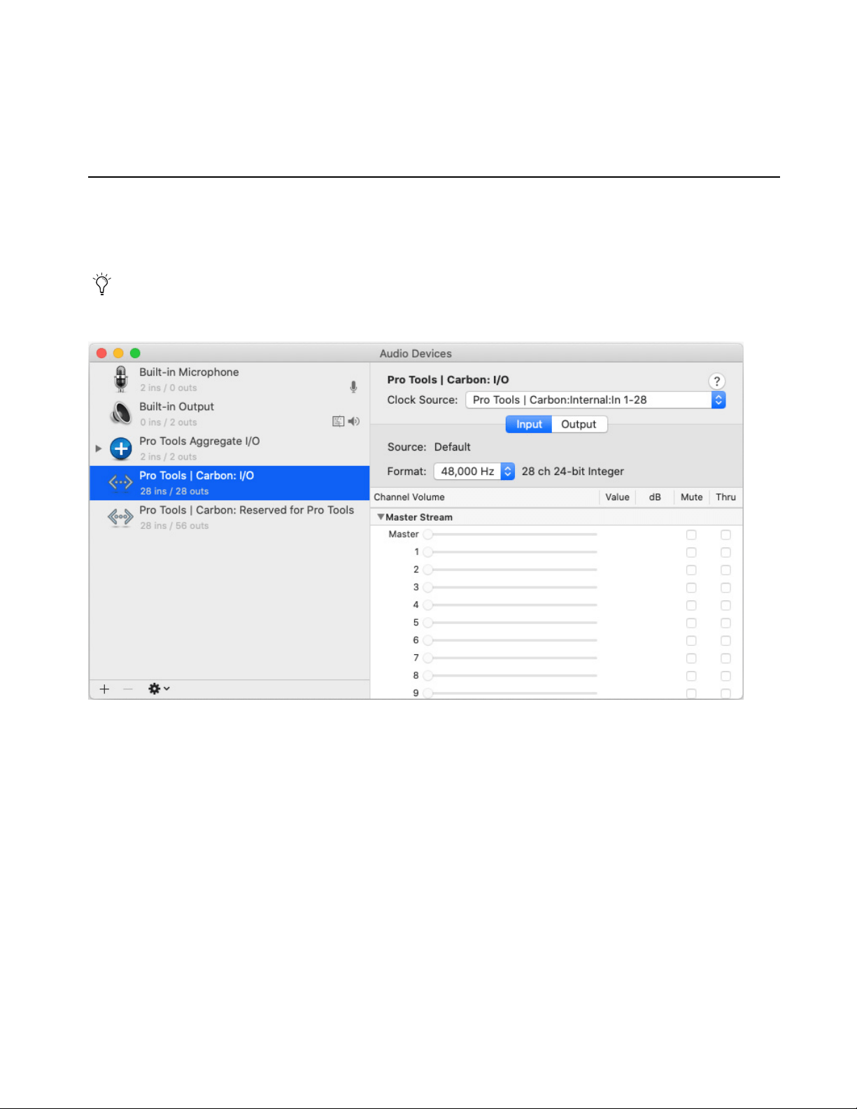
40
Appendix B: Pro Tools | Carbon Core Audio Devices
Pro Tools | Carbon presents two separate AVB Audio Devices in the Audio Devices list in AMS: Pro Tools | Carbon: I/O and
Pro Tools | Carbon: Reserved for Pro Tools. Note that when setting the Clock Source, default Sample Rate, or AVB Configuration
for Pro Tools Carbon, any changes you make to one device affects the other.
Pro Tools | Carbon: I/O
When using Pro Tools | Carbon with third-party Core Audio applications or for macOS system audio, the Pro Tools | Carbon: I/O
device must be used. The available AVB input and output channels are determined by the selected AVB Device Configuration
(see
AVB Device Configuration).
To use Pro Tools | Carbon for Mac System Sound Input and Output, select the “Pro Tools | Carbon: I/O” device in the Output
and the Input pages of the Sound System Preferences.
Pro Tools | Carbon: I/O device selected in AMS
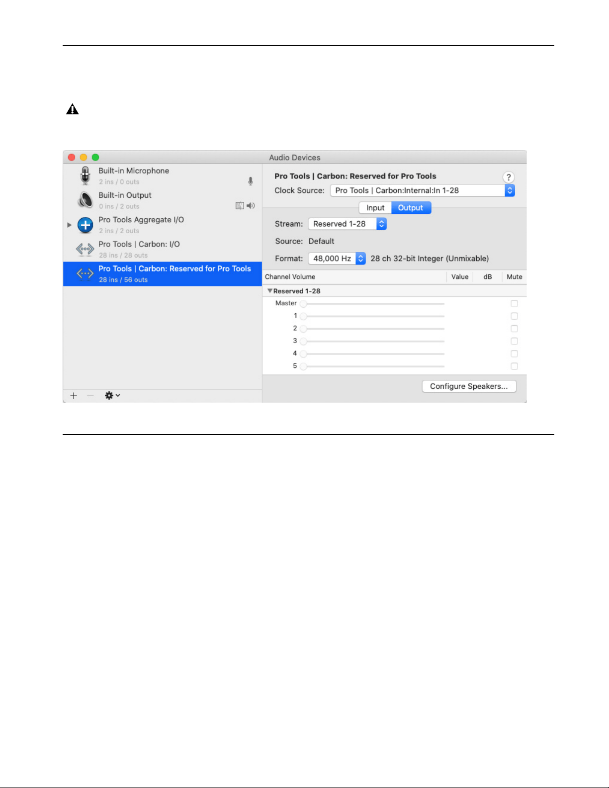
41
Pro Tools | Carbon: Reserved for Pro Tools
The Pro Tools | Carbon: Reserved for Pro Tools device is dedicated to Pro Tools. The available AVB input and output channels are
determined by the selected AVB Device Configuration (see AVB Device Configuration in AMS).
AVB Device Configuration
Pro Tools | Carbon requires a direct connection to a computer using AVB Ethernet. The AVB Ethernet connection provides up to 56 in-
put channels and 84 output channels of AVB audio between Pro Tools | Carbon and Pro Tools, and up to 28 input channels and 28 output
channels of AVB audio between Pro Tools | Carbon and third-party Core Audio–compatible software.
Pro Tools | Carbon provides six different AVB device configurations for input and output channels with Pro Tools or third-party Core
Audio–compatible software. The selected configuration determines the maximum number of record-enabled input channels and the
maximum number of output channels in DSP Mode available in Pro Tools.
Certain configurations also affect the number of available channels when using the Pro Tools | Carbon: I/O device with third-party Core
Audio applications. Use a smaller configuration to reduce the load on the host processor. Use a larger configuration to increase mixing
capacity in Pro Tools for more complex routing of low latency paths using DSP Mode.
Never use the “Pro Tools | Carbon: Reserved for Pro Tools” device for Mac System Sound Input or Output (System Preferences>
Sound). Only use the “Pro Tools | Carbon: I/O” device for Mac System Sounds.
Pro Tools | Carbon: Reserved for Pro Tools device selected in AMS
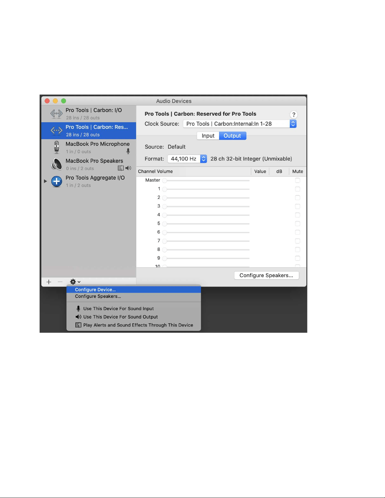
42
To set the device configuration:
1 Launch Audio MIDI Setup (AMS).
2 In the Audio Devices window, select Pro Tools | Carbon: Reserved for Pro Tools in the Audio Devices list.
3 Do one of the following:
• From the Configure Selected Device menu, choose Configure Device.
• Right-click Pro Tools | Carbon: Reserved for Pro Tools in the Audio Devices list and choose Configure Device.
Choosing Configure Device for Pro Tools | Carbon: Reserved for Pro Tools device
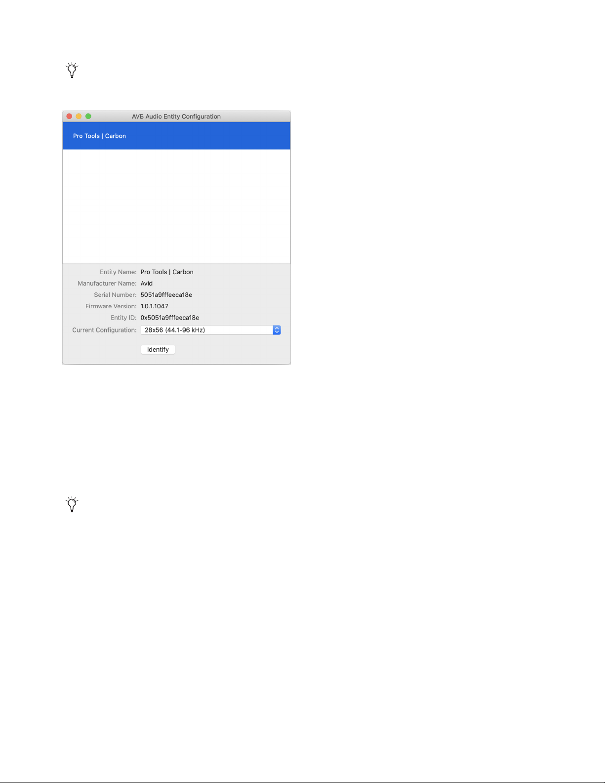
43
4 In the resulting AVB Audio Entity Configuration window, select Pro Tools | Carbon.
5 From the Current Configuration selector, select the configuration that best suits your workflow:
• 28x56 (44.1–96 kHz)
• 56x56 (44.1–96 kHz)
• 56x84 (44.1–96 kHz)
• 28x42 (44.1-192 kHz)
• 28x56 / 14x14 (44.1-192 kHz)
• 42x56 / 14x14 (44.1-192 kHz)
6 Quit the AVB Audio Configuration application (AVB Audio Configuration > Quit, or press Command+Q).
If the AVB Audio Entity Configuration window does not appear automatically, choose Window > Audio Entity Configuration
(or press Command+1).
AVB Audio Entity Configuration window
In Pro Tools, the System Usage window shows the number of available Input Channels and Output Channels for the selected
configuration, and how many are currently in use by the open session. See
System Usage.
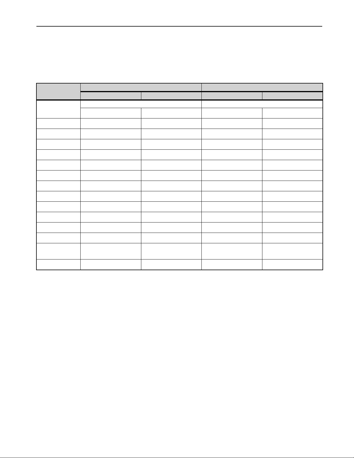
44
AVB Channel to Physical I/O Mappings for the Pro Tools | Carbon: I/O Device
The following table is for the Pro Tools | Carbon: I/O device with these AVB configurations:
• 28x56 (44.1–96 kHz)
• 56x56 (44.1–96 kHz)
• 56x84 (44.1–96 kHz)
AVB Channels
44.1–48 kHz 88.2–96 kHz
AVB In 1–28 AVB Out 1–28 AVB In 1–28 AVB Out 1–28
Pro Tools | Carbon I/O Pro Tools | Carbon I/O
In 1–28 Out 1–28 In 1–28 Out 1–28
1–2 Mic/Line/Inst 1–2 Mon L–R Mic/Line/Inst 1–2 Mon L–R
3–4 Mic/Line 3–4 Line 1–2 Mic/Line 3–4 Line 1–2
5–6 Mic/Line 5–6 Line 3–4 Mic/Line 5–6 Line 3–4
7–8 Mic/Line 7–8 Line 5–6 Mic/Line 7–8 Line 5–6
9–10 ADAT 1 1–2 Line 7–8 ADAT 1 1–2 Line 7–8
11–12 ADAT 1 3–4 HP 1 ADAT 1 3–4 HP 1
13–14 ADAT 1 5–6 HP 2 — HP 2
15–16 ADAT 1 7–8 HP 3 — HP 3
17–18 ADAT 2 1–2 HP 4 ADAT 2 1–2 HP 4
19–20 ADAT 2 3–4 ADAT 1 1–2 ADAT 2 3–4 ADAT 1 1–2
21–22 ADAT 2 5–6 ADAT 1 3–4 — ADAT 1 3–4
23–24 ADAT 2 7–8 ADAT 1 5–6 — —
25–26 (25) Talkback
(26) —
ADAT 1 7–8 (25) Talkback
(26) —
—
27–28 ADAT 2 1–2 ADAT 2 1–2
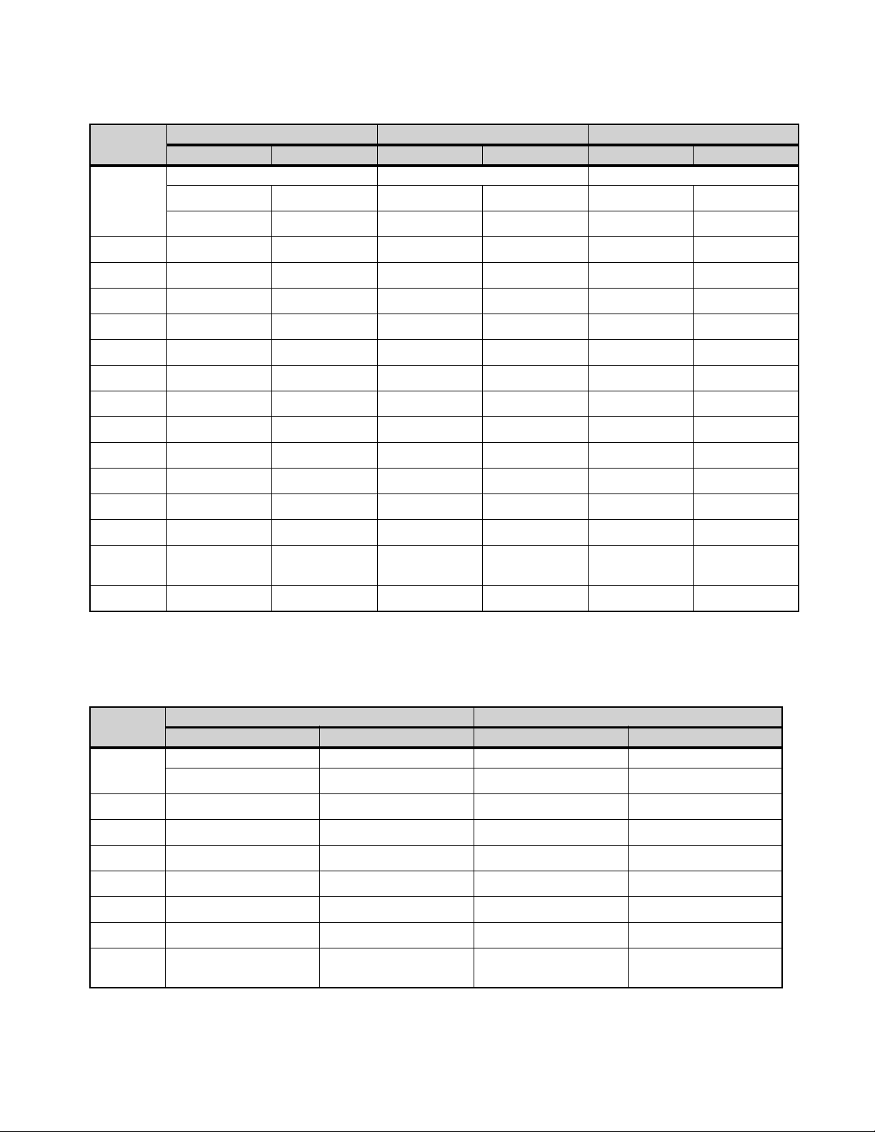
45
The following table is for the Pro Tools | Carbon: I/O device with this AVB configuration:
• 28x42 (44.1–192 kHz)
The following table is for the Pro Tools | Carbon: I/O device with these AVB configurations:
• 28x56 / 14x14 (44.1–192 kHz)
• 42x56 / 14x14 (44.1–192 kHz)
AVB
Channels
44.1–48 kHz 88.2–96 kHz 176.4–192 kHz
AVB In 1–28 AVB Out 1–28 AVB In 1–28 AVB Out 1–28 AVB In 1–28 AVB Out 1–28
Pro Tools | Carbon I/O Pro Tools | Carbon I/O Pro Tools | Carbon I/O
In 1–14 Out 1–14 In 1–14 Out 1–14 In 1–14 Out 1–14
In 15–28 Out 15–28 In 15–28 Out 15–28 In 15–28 Out 15–28
1–2 Mic/Line/Inst 1–2 Mon L–R Mic/Line/Inst 1–2 Mon L–R Mic/Line/Inst 1–2 Mon L–R
3–4 Mic/Line 3–4 Line 1–2 Mic/Line 3–4 Line 1–2 Mic/Line 3–4 Line 1–2
5–6 Mic/Line 5–6 Line 3–4 Mic/Line 5–6 Line 3–4 Mic/Line 5–6 Line 3–4
7–8 Mic/Line 7–8 Line 5–6 Mic/Line 7–8 Line 5–6 Mic/Line 7–8 Line 5–6
9–10 ADAT 1 1–2 Line 7–8 ADAT 1 1–2 Line 7–8 ADAT 1 1–2 Line 7–8
11–12 ADAT 1 3–4 HP 1 ADAT 1 3–4 HP 1 — HP 1
13–14 ADAT 1 5–6 HP 2 — HP 2 — HP 2
15–16 ADAT 1 7–8 HP 3 — HP 3 — HP 3
17–18 ADAT 2 1–2 HP 4 ADAT 2 1–2 HP 4 ADAT 2 1–2 HP 4
19–20 ADAT 2 3–4 ADAT 1 1–2 ADAT 2 3–4 ADAT 1 1–2 — ADAT 1 1–2
21–22 ADAT 2 5–6 ADAT 1 3–4 — ADAT 1 3–4 — —
23–24 ADAT 2 7–8 ADAT 1 5–6 — — — —
25–26 (25) Talkback
(26) —
ADAT 1 7–8 (25) Talkback
(26) —
— (25) Talkback
(26) —
—
27–28 ADAT 2 1–2 ADAT 2 1–2 ADAT 2 1–2
AVB
Channels
44.1–96 kHz 176.4–192 kHz
AVB In 1–14 AVB Out 1–14 AVB In 1–14 AVB Out 1–14
Pro Tools | Carbon I/O Pro Tools | Carbon I/O Pro Tools | Carbon I/O Pro Tools | Carbon I/O
In 1–14 Out 1–14 In 1–14 Out 1–14
1–2 Mic/Line/Inst 1–2 Mon L–R Mic/Line/Inst 1–2 Mon L–R
3–4 Mic/Line 3–4 Line 1–2 Mic/Line 3–4 Line 1–2
5–6 Mic/Line 5–6 Line 3–4 Mic/Line 5–6 Line 3–4
7–8 Mic/Line 7–8 Line 5–6 Mic/Line 7–8 Line 5–6
9–10 ADAT 1 1–2 Line 7–8 ADAT 1 1–2 Line 7–8
11–12 ADAT 1 3–4 HP 1 — HP 1
13–14 (13) ADAT 2 1
(14) Talkback
HP 2 (13) ADAT 2 1
(14) Talkback
HP 2
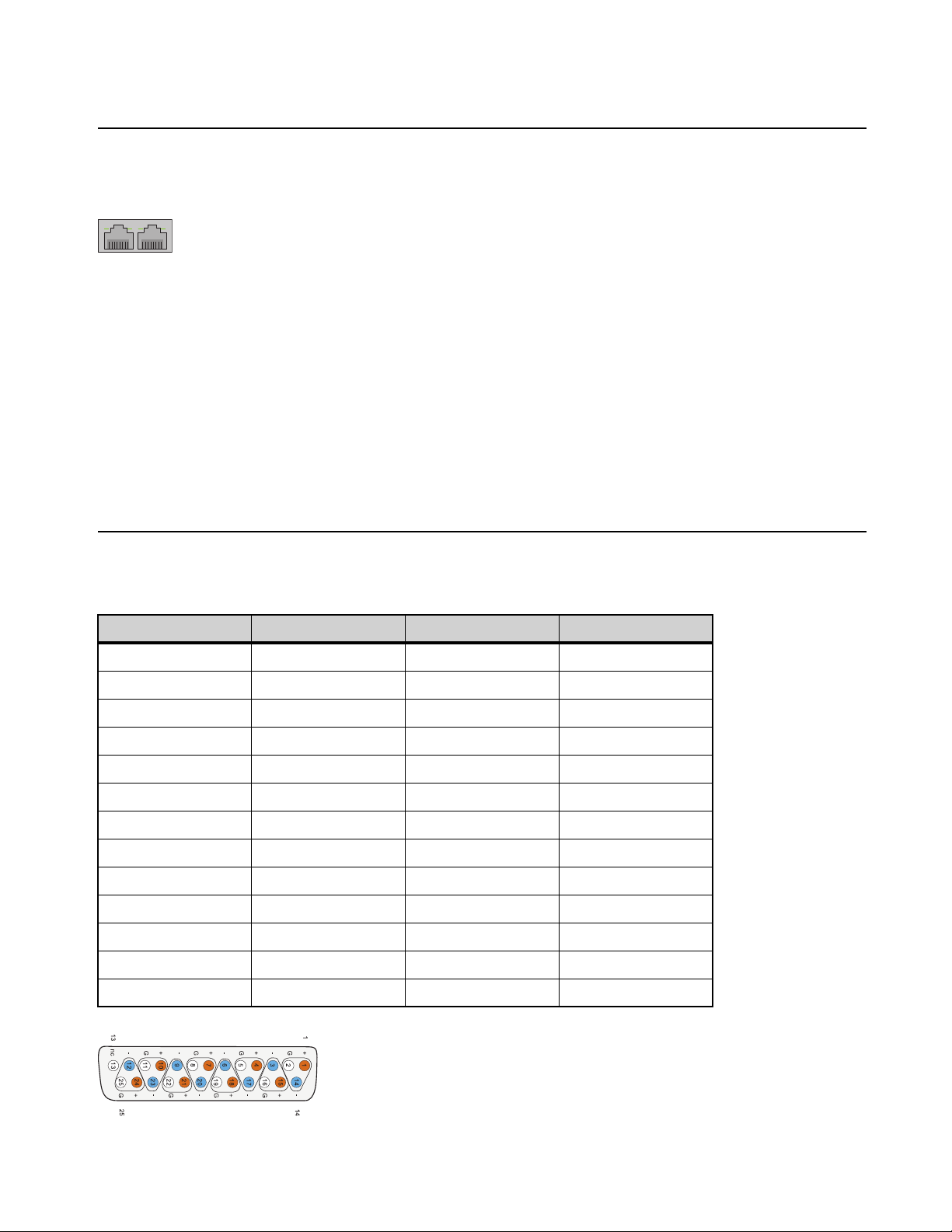
46
Appendix C: Pro Tools | Carbon Pin Out Diagrams
Ethernet, RJ45 Connector, Gigabit
Pro Tools | Carbon connects to your Pro Tools system using Ethernet. Pro Tools both controls the unit over Ethernet and streams audio
over Ethernet using AVB (see Connect Ethernet).
Pin 1
BI_DA+
Pin 2
BI_DA–
Pin 3
BI_DB+
Pin 4
BI_DC+
Pin 5
BI_DC–
Pin 6
BI_DB–
Pin 7
BI_DD+
Pin 8
BI_DD–
DB25 Pin Out Connections Channels 1–8
Connections for the 25-pin D-sub connector are listed in the table below. The pinning is according to the proprietary Tascam standard.
Pin number Function Pin number Function
1 AIN/OUT 8 + 14 AIN/OUT 8 –
2 GND 15 AIN/OUT 7 +
3 AIN/OUT 7 – 16 GND
4 AIN/OUT 6 + 17 AIN/OUT 6 –
5 GND 18 AIN/OUT 5 +
6 DOUT 2/6 + 19 GND
7 AIN/OUT 4 + 20 AIN/OUT 4 –
8 GND 21 AIN/OUT 3 +
9 AIN/OUT 3 – 22 GND
10 AIN/OUT 2 + 23 AIN/OUT 2 –
11 GND 24 AIN/OUT 1 +
12 AIN/OUT 1 – 25 GND
13 N.C.
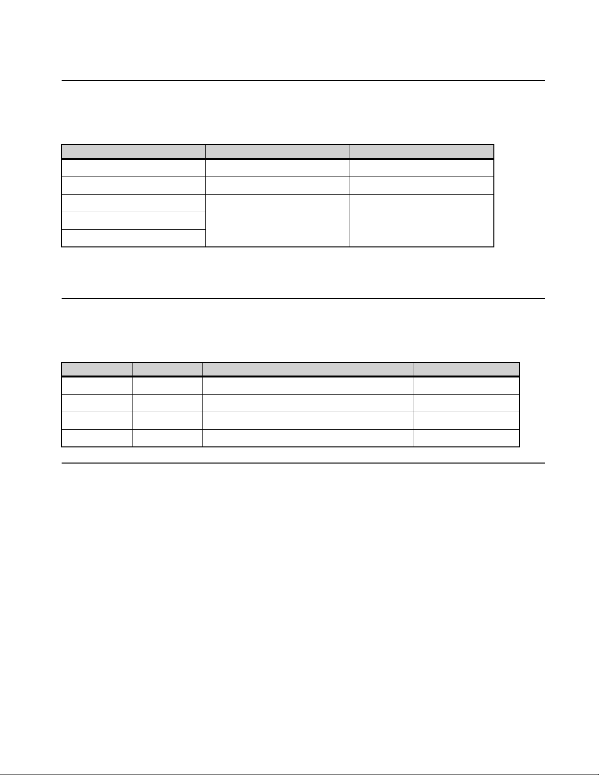
47
Appendix D: Network Port Usage
Required Access for Normal Operation
The following services are required for normal operation of Pro Tools | Carbon. The actual ports that are used in the reserved range may
vary depending on the firmware version that is running on the device.
In addition, Pro Tool | Carbon requires an mDNS service to be running on the connected Mac host.
mDNS is enabled by default on macOS.
Access for Customer Support
The following services are not required for normal operation of the device, but may be required for certain procedures requested by Avid
customer support. Services that are disabled by default may be enabled when following instructions from Avid customer support.
Network Security
Pro Tools | Carbon should not be made visible to network devices beyond the Mac host. Do not connect Pro Tools | Carbon to a bridged
network interface on your Mac.
Port Protocol Purpose
5556 TCP Diagnostics
6655-6670 TCP Control and communication
5353 UDP mDNS Discovery and connection
51792
57531
Port Protocol Purpose Enabled by Default
21 TCP FTP for device firmware repair No
22 TCP SSH and SFTP for troubleshooting and firmware repair Yes
23 TCP Telnet for device access and diagnostics No
80 TCP HTTP for device status information and log collection Yes