
Effect Reference Guide
Introduction
This guide explains the parameters and technical terms that are used in the effects of
Yamaha mixers and audio interfaces.
You should use this guide together with the documentation unique to the product.
Read the documentation first and use this reference guide to learn more about
parameters and terms.
Information
The contents of this guide and the copyrights thereof are under exclusive ownership
by Yamaha Corporation.
The company names and product names in this guide are the trademarks or
registered trademarks of their respective companies.
Some functions and parameters in this guide may not be provided in your product.
The information in this guide is current as of January 2026.
EN

2
Effect Reference Guide
contents
EQ / Channel Section ............................................................................................3
PEQ (Parametric Equalizer) .......................................................................................................3
SSMCS (Sweet Spot Morphing Channel Strip) .........................................................................4
Dynamics Section .................................................................................................6
GATE .........................................................................................................................................6
COMP (Compressor) .................................................................................................................7
COMPANDER–H / COMPANDER–S .........................................................................................8
DUCKER....................................................................................................................................9
M.B.COMP (Multi-band Compressor) .....................................................................................10
Pitch / Vocal Processing Section ......................................................................12
PITCH FIX ................................................................................................................................ 12
Amp / Guitar Section ..........................................................................................14
GUITAR AMP CLASSICS ........................................................................................................14
Cabinet types and characteristics ..........................................................................................16
Reverb Section ....................................................................................................17
REV−X .....................................................................................................................................17
REV R3 ....................................................................................................................................19
Delay Section .......................................................................................................21
MONO DELAY ......................................................................................................................... 21
PING PONG DELAY ................................................................................................................22
3
Effect Reference Guide
EQ / Channel Section
PEQ (Parametric Equalizer)
A parametric equalizer (PEQ) is a high–precision equalizer that allows you to select specific frequency
bands of an audio signal and freely adjust the gain (boost/cut) and bandwidth (Q) of those bands.
It is suitable for a wide range of applications, such as sound quality correction, acoustic space
optimization, and feedback suppression.
Parameters
Parameter Name Description Example Range
Frequency
Sets the cutoff/center frequency to be boosted
or cut according to the gain setting.
20.0 Hz–20.0 kHz
Gain
Sets the amount of boost/cut for the signal level
near the frequency set by Frequency.
−18.0 dB–+18.0 dB
Q
Sets the bandwidth to be boosted/cut. The
larger the value, the narrower the affected band.
16.0–0.1
Filter Type
Selects the filter type for each band (peak,
shelving, HPF/LPF, etc.).
Peak, High Shelf,
Low Shelf, HPF,
LPF
Bypass
Disables PEQ processing for each band or the
entire signal.
On, Off
1−Knob On/Off Sets the 1–Knob Control On/Off. On, Off
1−Knob Type Sets the type of 1–Knob control.
Intensity, Vocal,
Loudness
1−Knob Level Sets the level of 1–Knob control. 0–100
Recommended Settings by Application
Application Recommended Setting Example
Improve vocal clarity 2.5 kHz at +3 dB, Q = 1.2
Remove muddiness in
low frequencies
200 Hz at −4 dB, Q = 1.0
Feedback suppression 6.3 kHz at −12 dB, Q = 10
Speaker correction 80 Hz at +2 dB (low shelf), 10 kHz at +3 dB (high shelf)
4
Effect Reference Guide
SSMCS (Sweet Spot Morphing Channel Strip)
SSMCS is a channel strip effect developed by Yamaha that combines a compressor and equalizer.
Based on presets condensed from professional engineers’ expertise, it features a “Morphing” function
that allows multiple parameters to be changed simultaneously with a single knob, enabling easy and
intuitive sound creation.
SSMCS consists of the following two main sections:
• COMP (Compressor)
Controls volume peaks and adjusts dynamics. The Morphing knob allows simultaneous adjustment
of multiple compressor parameters (Ratio, Attack, Release, Knee, etc.).
• EQ (Equalizer)
Three–band structure (Low/Mid/High), with Frequency (F), Gain (G), and Q (Mid only) settings
for each band. Low/High use shelf filters, Mid uses a peak filter. The Morphing knob allows
simultaneous adjustment of multiple equalizer parameters (Frequency, Gain, Q).
Common Parameters for Compressor and Equalizer
Parameter Name Description Example Range
Morphing Sets the intensity of the preset.
Continuous change
between presets
Sweet Spot Data For selecting the Sweet Spot Data. Varies by setting
Call up Sweet Spot Data suitable for your application and adjust the Morphing parameter to find the
optimal point.
Comp Section Parameters
Parameter Name Description Example Range
Comp Drive
Adjusts the degree to which the compressor is
applied.
0.00–10.0
Knee
Sets how gently compression starts near the
threshold.
Soft / Medium / Hard
Ratio Sets the amount of compressor effect. 1.0:1–20:1–500:1, INF:1
Attack
Sets the time that elapses until the compressor
effect starts.
0.092 ms–80.0 ms
Release
Sets the time that elapses until the compressor
effect is released.
9.3 ms–999.0 ms
Side Chain
When set to On, the compressor is enabled to
affect the side chain level detection.
On, Off
5
Effect Reference Guide
Parameter Name Description Example Range
SC−Q
This sets the width of the boost/cut band for the
Side Chain that is turned on. Higher values affect
narrower bands.
0.5–16
SC−Freq.
Sets the Side Chain cutoff frequency.
This determines the frequency that is boosted/
cut (increased/decreased) depending on the gain
setting.
20 Hz–20 kHz
SC−Gain
Determines how much to boost/cut (increase/
decrease) the signal level around the frequency
set by Side Chain SC–Freq.
−18 dB–+18 dB
EQ Section Parameters
Parameter Name Description Example Range
Q
Sets the width of the band to be boosted/cut.
Higher values affect narrower bands.
0.5–16.0
Frequency
Sets the cutoff frequency. This determines the
frequency that will be boosted/cut (increased/
decreased) depending on the gain setting.
20 Hz–20 kHz
Gain
Determines how much the signal level around the
frequency set by the Frequency control will be
boosted or cut.
−18 dB–+18 dB
Band Frequency Range Gain Q Filter Type
Low 20 Hz–1 kHz −18 dB–+18 dB None Low Shelf
Mid 20 Hz–20 kHz −18 dB–+18 dB 0.50–16.00 Peak
High 500 Hz–20 kHz −18 dB–+18 dB None High Shelf
6
Effect Reference Guide
Dynamics Section
GATE
Gate is a dynamics effect that closes a gate (mutes the audio signal) when the input signal is below the
set threshold, attenuating or cutting off the signal to remove unwanted noise and ambient sounds. It is
particularly effective at cutting out quiet parts and ambient noise when using a microphone, improving
the quality of your streaming and recordings.
Parameters
Parameter Name Description Example Range
Threshold
Sets the threshold level at which the gate effect
is applied.
−72.0 dB–0.0 dB
Range
Sets the amount of gate closure (signal
attenuation) when the input signal falls below the
threshold.
−∞ dB–0.0 dB
Attack
Sets how quickly the gate opens after the input
signal level exceeds the Threshold.
0.092 ms–80 ms
Hold
Sets the time that elapses before the gate begins
to close after the input signal level drops below
the Threshold.
0.02 ms–1960.0 ms
Decay
Sets how quickly the gate closes after the input
signal has passed the Hold wait time.
9.3 ms–999.0 ms
Recommended Settings by Application
Application Recommended Setting Example
Noise removal during vocal
recording
Threshold: −45 dB / Range: −∞ dB / Attack: 10 ms / Hold: 300 ms
Decay: 200 ms
Ambient noise cut during live
streaming
Threshold: −50 dB / Range: −12 dB / Attack: 5 ms / Hold: 500 ms
Decay: 150 ms
Silence processing during
instrument recording
Threshold: −40 dB / Range: −6 dB / Attack: 20 ms / Hold: 250 ms
Decay: 100 ms
7
Effect Reference Guide
COMP (Compressor)
Compressor is a dynamics effect that compresses the parts of the input signal that exceed a set
threshold, smoothing out volume changes. By suppressing peaks, it stabilizes the overall volume
balance for a professional finish.
Parameters
Parameter Name Description Example Range
Threshold Sets the threshold level for the compressor effect. −54.0 dB–0.0 dB
Ratio Sets the amount of compressor effect.
1.0:1–20:1–
500:1, INF:1
Gain Sets the output level of the compressor. 0.0–18.0 dB
Auto Makeup
Automatically compensates for gain loss due to
compression.
On, Off
Attack
Sets the speed at which the compressor effect
reaches maximum after the input signal exceeds the
threshold.
0.092 ms–80.00 ms
Release
Sets the time that elapses until the compressor effect
stops after the input signal falls below the threshold.
9.3–999.0 ms
Knee
Sets how gently compression starts near the
threshold.
Soft: natural volume change.
Medium: intermediate volume change.
Hard: clear, abrupt volume change.
Soft / Medium / Hard
Recommended Settings by Application
Application Recommended Setting Example
Vocal Threshold: −40 dB / Ratio: 3:1 / Attack: 20 ms / Release: 80 ms / Knee: Medium
Guitar Threshold: −35 dB / Ratio: 2:1 / Attack: 10 ms / Release: 100 ms / Knee: Soft
Drums Threshold: −30 dB / Ratio: 5:1 / Attack: 5 ms / Release: 150 ms / Knee: Hard
8
Effect Reference Guide
COMPANDER–H / COMPANDER–S
COMPANDER–H / COMPANDER–S are composite dynamics effects combining compressor,
expander, and limiter. They suppress volume changes while simultaneously reducing ambient noise,
providing stable sound quality for streaming, recording, and live performance.
COMPANDER−H
Large noise attenuation, excellent for removing ambient sounds. Effective for
suppressing noise in quiet scenes.
COMPANDER−S
Moderate noise attenuation, processes noise slightly while maintaining
natural sound quality. Suitable for situations emphasizing musical nuance.
Parameters
Parameter Name Description Example Range
Threshold Sets the threshold level for the compressor effect. −54.0 dB–0.0 dB
Ratio Sets the amount of compressor effect. 1.0:1–20:1
Attack
Sets the time that elapses until the set level is reached
after the input signal exceeds three boundary levels.
0–120 ms
Release
Sets the time that elapses until the set level is released
after the input signal exceeds three boundary levels.
5.0 ms–42.3 s
OutGain Sets the output level. 0.0 dB–−18 dB
Width
Sets the width of the boundary levels between
compressor and expander.
1–90 dB
Recommended Settings by Application
Application Type Recommended Setting Example
Vocal recording COMPANDER–S
Threshold: −40 dB / Ratio: 2:1 / Attack: 20 ms
/ Release: 80 ms / OutGain: −6 dB
Streaming with
emphasis on noise
suppression
COMPANDER–H
Threshold: −50 dB / Ratio: 5:1 / Attack: 10 ms
/ Release: 120 ms / OutGain: −12 dB
Instrument recording
(acoustic)
COMPANDER–S
Threshold: −35 dB / Ratio: 1.5:1 / Attack: 40 ms /
Release: 100 ms / OutGain: −3 dB
9
Effect Reference Guide
DUCKER
A ducker is an effect that detects a trigger input signal and automatically attenuates (reduces) the
volume. It is mainly used to automatically lower background music when narration or vocals are
present, achieving a natural mix balance without manual fader operation.
Parameters
Parameter Name Description Example Range
Ducker Source
Sets the signal used to determine the strength of the
ducker.
Any input channel
Threshold
Sets the threshold level at which the ducker effect is
applied.
−60 dB–0 dB
Range
Sets the amount of attenuation when the ducker effect
is applied.
−70 dB–0 dB
−∞ dB–0.0 dB
Attack
Sets how quickly the volume lowers after the input
signal level exceeds the “Threshould”.
0.092 ms–80.00 ms
Decay
Sets how quickly the volume returns after the input
signal level falls below the “Threshould”.
1.3 ms–5.0 s
9.3 ms–999.0 ms
Recommended Settings by Application
Application Recommended Setting Example
Background music with
narration
Source: Mic IN / Threshold: −40 dB / Range: −12 dB Attack: 10 ms /
Decay: 300 ms
Automatic mute for
conference audio
Source: Voice IN / Threshold: −50 dB / Range: −∞ dB Attack: 5 ms /
Decay: 500 ms
Prioritize talk during live
performance
Source: Vocal Mic / Threshold: −45 dB / Range: −6 dB Attack: 20
ms / Decay: 200 ms
10
Effect Reference Guide
M.B.COMP (Multi-band Compressor)
A multi–band compressor divides the audio signal into three frequency bands (LOW, MID, and
HIGH) and applies independent compression to each, enabling more precise dynamics control. By
suppressing volume changes in each band, it improves level stability during streaming and recording,
resulting in a balanced sound.
Parameters
Parameter Name Description Example Range
1−knob On/Off
This function controls the effect of Multi–Band
Compressor with a single slider. When this is set to
On, Threshold, Ratio, and Gain for each band are
adjusted according to the 1–knob Level.
ATTACK, RELEASE and XOVER frequencies are fixed
values.
On, Off
1−Knob Level Sets the level of 1–Knob control. 0–48
Gain Sets the volume for the target band. −∞, –60 dB–+18 dB
L−M XOVER
Sets the crossover frequency between the LOW band
and MID band.
21.2 Hz–4.00 kHz
M−H XOVER
Sets the crossover frequency between the MID band
and HIGH band.
42.5 Hz–8.00 kHz
Bypass
Enables/disables bypass for the compressor of the
target band.
On, Off
Attack Time
Sets the attack time for the compressor of the target
band. This adjusts the time it takes for the compressor
to reach its maximum effect after the input signal
exceeds the threshold.
1 ms–200 ms
Release Time
Sets the release time for the compressor (all bands).
This sets the time it takes for the compressor effect to
stop after the input signal falls below the threshold.
10 ms–3000 ms
Threshold
Sets the threshold for the compressor of the target
band. This sets the level at which the compressor
effect is applied.
−54 dB–−6 dB
Ratio
Sets the ratio for the compressor of the target band.
This sets the amount of compression applied.
1.0:1–20.0:1
Out Gain Sets the overall output level. −12 dB–+12 dB

11
Effect Reference Guide
Recommended Settings by Application
Application Recommended Setting Example
Live streaming
LOW: Threshold −30 dB / Ratio 3:1 / Gain +2 dB
MID: Threshold −25 dB / Ratio 2.5:1 / Gain +1 dB
HIGH: Threshold −20 dB / Ratio 2:1 / Gain 0 dB
Vocal processing
LOW: Light compression / MID: Emphasis on clarity /
HIGH: Suppress harsh sibilance
Mastering Apply even compression to all bands to stabilize loudness
12
Effect Reference Guide
Pitch / Vocal Processing Section
PITCH FIX
PITCH FIX is an effect that corrects the pitch of input audio in real time. It automatically adjusts the
pitch of vocals or narration, resulting in stable phrasing. Additionally, flexible settings are available,
such as formant (voice quality) adjustment and specifying the target notes for correction via MIDI
control.
Combines the following two main processes for pitch correction:
Manual pitch correction: Corrects pitch and formant to manually set values.
Automatic pitch correction: Automatically corrects input audio pitch to match the specified key and
scale.
Parameters
Parameter Name Description Example Range
Coarse Sets pitch deviation in semitone units. −12–+12
Fine Sets pitch deviation in cent units. −50–+50
Formant Sets the formant (voice quality). −62–+62
Mix
Sets the volume balance before and after pitch
correction.
0–126
Key Selects the key for automatic correction. C–B
Scale Selects the scale for automatic correction.
Chromatic, Major, Minor,
Pentatonic, etc.
Note Low Limit
Sets the lower limit of the range for automatic
correction.
C−2–G8
Note High Limit
Sets the upper limit of the range for automatic
correction.
C−2–G8
Correction Enables/disables automatic correction. On, Off
MIDI Control Selects the mode for MIDI control. Off, Setting, Real Time
Speed Sets the speed of correction tracking. 0–100
Tolerance Sets sensitivity to pitch changes. 0–100

13
Effect Reference Guide
Recommended Settings by Application
Application Recommended Setting Example
Natural vocal correction Key: C / Scale: Major / Speed: 60 / Tolerance: 40 / Mix: 100
Robot voice style Key: C / Scale: Chromatic / Speed: 100 / Tolerance: 0 / Formant: +40
Stabilize narration Correction: On / Speed: 30 / Tolerance: 60 / Note Limit: C2–C5
14
Effect Reference Guide
Amp / Guitar Section
GUITAR AMP CLASSICS
Guitar Amp Classics are guitar amp simulations that make extensive use of advanced Yamaha
modeling technology. Four types with different sound characters are available: CLEAN, CRUNCH,
LEAD, and DRIVE, suitable for a wide range of genres and playing styles.
CLEAN Clear sound characteristic of transistor amps. Ideal for clean tones.
CRUNCH Lightly distorted sound for blues and rock. Vintage tube amp style.
LEAD High–gain, rich harmonic tube amp sound. Ideal for lead guitar.
DRIVE Strongly distorted sound for hard rock/metal. Wide range of distortion expression.
Parameters
Common Parameters for CLEAN/CRUNCH/DRIVE/LEAD
Parameter Name Description Example Range
Treble, Middle,
Bass
Adjusts the level of high/mid/low frequencies. 0–10
Presence Emphasizes high–frequency overtones. 0–10
Off / Gate Switches the noise gate On/Off. On, Off
Gate level Adjusts the threshold for the gate. 0–10
SP Type
Selects the SP TYPE. For details, see “Cabinet Types and
Features.”
0–8
Mic Position Sets the microphone position. Center or Edge
Output Adjusts the final output level. −∞ dB–0 dB
15
Effect Reference Guide
CLEAN Only
Parameter Name Description Example Range
Volume Adjusts input level. 0–10
Distortion Adjusts amount of distortion. 0–10
Cho/OFF/Vib:
Switches effect On/Off. “Cho” enables chorus, while “Vib”
enables vibrato.
Speed/Depth Sets vibrato speed/depth when “Vib” is On. 0–10
Blend
Adjusts balance between original and effect sound
(CLEAN only).
0.0–10.0
CRUNCH Only
Parameter Name Description Example Range
Normal/Bright Switches sound character.
Gain Sets input level. Higher values increase distortion. 0–10
LEAD Only
Parameter Name Description Example Range
High/Low Switches sound character.
Gain Sets input level. Higher values increase distortion. 0–10
Master Sets preamp output level. 0–10
DRIVE Only
Parameter Name Description Example Range
Amp Type Switches sound character. 1–6
Gain Sets input level. Higher values increase distortion. 0–10
Master Sets preamp output level. 0–10
16
Effect Reference Guide
Cabinet types and characteristics
The following table shows the cabinet characteristics that are common to each of the four
types: CLEAN, CRUNCH, DRIVE, and LEAD.
SP TYPE Characteristics
Speaker
configuration
BS 4×12 British flat stack type with rich cabinet resonance. 4×12"
AC 2×12
American combo type cabinet, featuring a clear tone for
versatile use in various music genres.
2×12"
AC 1×12
American combo type cabinet, featuring a clear tone for
ensemble use.
1×12"
AC 4×10
American combo type cabinet, featuring a bright tone
reminiscent of more traditional guitar sounds.
4×10"
BC 2×12
British combo type cabinet, ideal for distortion sounds and
featuring a wide range with broad treble response.
2×12"
AM 4×12
American stack type cabinet, ideal for matching with high–
power amplifiers and featuring a clear sound contour.
4×12"
YC 4×12
Yamaha F series combo type cabinet, featuring a rich midrange
and a mild high range.
4×12"
JC 2×12
Japanese combo type cabinet, ideal for clean sounds, and
featuring a rich mid–high range plus modulation effects.
2×12"
Recommended Settings by Application
Application Type Recommended Setting Example
Clean backing CLEAN
DISTORTION: 0 / BLEND: 50 /
TREBLE: 6 / BASS: 5
Blues solo CRUNCH
GAIN: 5 / TREBLE: 7 / MIDDLE: 6 /
BASS: 5
Rock lead LEAD
GAIN: 8 / MASTER: 7 / PRESENCE: 6
/ SP TYPE: AC 4×10
Metal riff DRIVE
GAIN: 10 / TREBLE: 8 / BASS: 6 /
GATE LEVEL: 7
17
Effect Reference Guide
Reverb Section
REV−X
REV–X is a high–quality digital reverb effect developed by Yamaha for professional audio equipment.
Inheriting the legacy of the classic REV5 and REV7 models, it is designed as an algorithm and widely
adopted in DSP–equipped devices and VST plugins. It excels at reproducing a sense of air and is
loved by engineers worldwide. You can select from three types: REV–X HALL, REV–X ROOM, and
REV–X PLATE.
REV−X HALL
Reproduces the spaciousness and depth of a concert hall. Creates a grand and
rich spatial feel.
REV−X ROOM
Simulates the natural reverberation of a studio or small room. Adds thickness to
the space while maintaining instrument and vocal localization.
REV−X PLATE
Simulates classic plate reverb using metal plates. Features clear and smooth
reverberation, ideal for vocal processing.
Parameters
Parameter Name Description Example Range
Reverb Time
Adjusts the reverb time. This parameter links
to Room Size.
The adjustable range varies depending on the
REV–X type.
Hall: 0.103 sec–31.0 sec
Room: 0.152 sec–45.3 sec
Plate: 0.176 sec–52.0 sec
*Minimum value when Room Size is 0 (min) to
Maximum value when Room Size is 31 (max)
Initial Delay
Adjusts the time that elapses between
the direct, original sound and the initial
reflections that follow it.
0.1 msec–200.0 msec
Decay
Adjusts the characteristic of the envelope
from the moment the reverberation starts to
the moment it attenuates and stops.
0–63
Room Size
Adjusts the size of the simulated room. This
parameter links to Reverb Time.
0–31
Diffusion Adjusts the spread of the reverberation. 0–10
HPF
Adjusts the cutoff frequency of the high pass
filter.
20 Hz–8 kHz
LPF
Adjusts the cutoff frequency of the low pass
filter.
1 kHz–20 kHz
Hi Ratio
Sets the length of high–frequency
reverberation.
0.1–1.0
18
Effect Reference Guide
Parameter Name Description Example Range
Low Ratio
Sets the length of low–frequency
reverberation.
0.1–1.4
Low Freq Adjusts the frequency of the Low Ratio. 22 Hz–18 kHz
Recommended Settings by Application
Application Type Recommended Setting Example
Vocal Plate Reverb Time: 1.8 s / High Ratio: High
Acoustic guitar Plate Reverb Time: 1.8 s / High Ratio: High
Drums Room Room Size: Small / Initial Delay: 20 ms
Strings Hall Reverb Time: 3.0 s / Diffusion: High
19
Effect Reference Guide
REV R3
REV R3 is a next–generation reverb effect that inherits the technology of the REV–X series, enabling
more flexible parameter settings and high–precision spatial expression. It features three types: Hall,
Room, and Plate. Widely used in professional audio equipment and VST plugins, it offers natural,
smooth reverberation and high spatial expressiveness for music production and live sound.
REV R3 HALL
Reproduces the spaciousness and depth of a concert hall. Creates a grand and
rich spatial feel.
REV R3 ROOM
Simulates the natural reverberation of a studio or small room. Adds thickness to
the space while maintaining instrument and vocal localization.
REV R3 PLATE
Simulates classic plate reverb using metal plates. Features clear and smooth
reverberation, ideal for vocal processing.
Parameters
Parameter Name Description Example Range
Reverb Time Adjusts the length of the reverberation. 0.3s–30.0s
Initial Delay Adjusts the time that elapses before reverberation begins.
0.1 msec–
200.0 msec
Hi Ratio
Sets the ratio of high–frequency reverberation time to REV
TIME.
0.1–1.0
Diffusion Adjusts the density and spread of the reverberation. 0–10
Density Sets the density of the reverberation. 0–4
HPF Sets the cutoff frequency for the high–pass filter.
Thru, 21.2 Hz–
8.00 kHz
LPF Sets the cutoff frequency for the low–pass filter.
50.0 Hz–16.0
kHz, Thru
ER/
Reverb Delay
Sets the delay time from early reflections to reverb sound. 0.1 ms–200 ms
ER/Rev Balance
Sets the level balance between early reflections and
reverb sound.
E63>R–E<R63
Feedback Gain Sets the amount of feedback for the initial delay. −99%–+99%

20
Effect Reference Guide
Recommended Settings by Application
Application Type Recommended Setting Example
Vocal Plate
Reverb Time: 1.5 s / Diffusion: 7 / High Ratio: 0.8 / LPF: 12
kHz
Acoustic guitar Room Reverb Time: 1.2 s / Density: 3 / HPF: 100 Hz / LPF: 10 kHz
Drums Hall
Reverb Time: 2.5 s / Initial Delay: 50 ms / Diffusion: 10 / ER/
Rev Balance: E=R
Cinematic (movie style) Hall Reverb Time: 4.0 s / Density: 4 / High Ratio: 1.0 / LPF: 16 kHz
21
Effect Reference Guide
Delay Section
MONO DELAY
Mono Delay is a simple delay effect that adds a delayed signal to the input, creating spatial width and
rhythmic feel. Its monaural configuration makes it easy to use for vocals, guitar, synth, and more. It
supports tempo synchronization, allowing delay time settings to match the song’s BPM.
Parameters
Parameter Name Description Example Range
Delay Sets the delay time.
0.1ms–2700.0ms
1.0ms–1350.0ms
Feedback Gain Sets the amount of repeated delayed sound. −99%–+99%
High Ratio Sets the amount of high–frequency feedback. 0.1–1.0
HPF Sets the cutoff frequency for the high–pass filter. Thr, 21.2 Hz–8 kHz
LPF Sets the cutoff frequency for the low–pass filter. 50 Hz–16 kHz, Thru
Sync Enables/disables tempo synchronization. On, Off
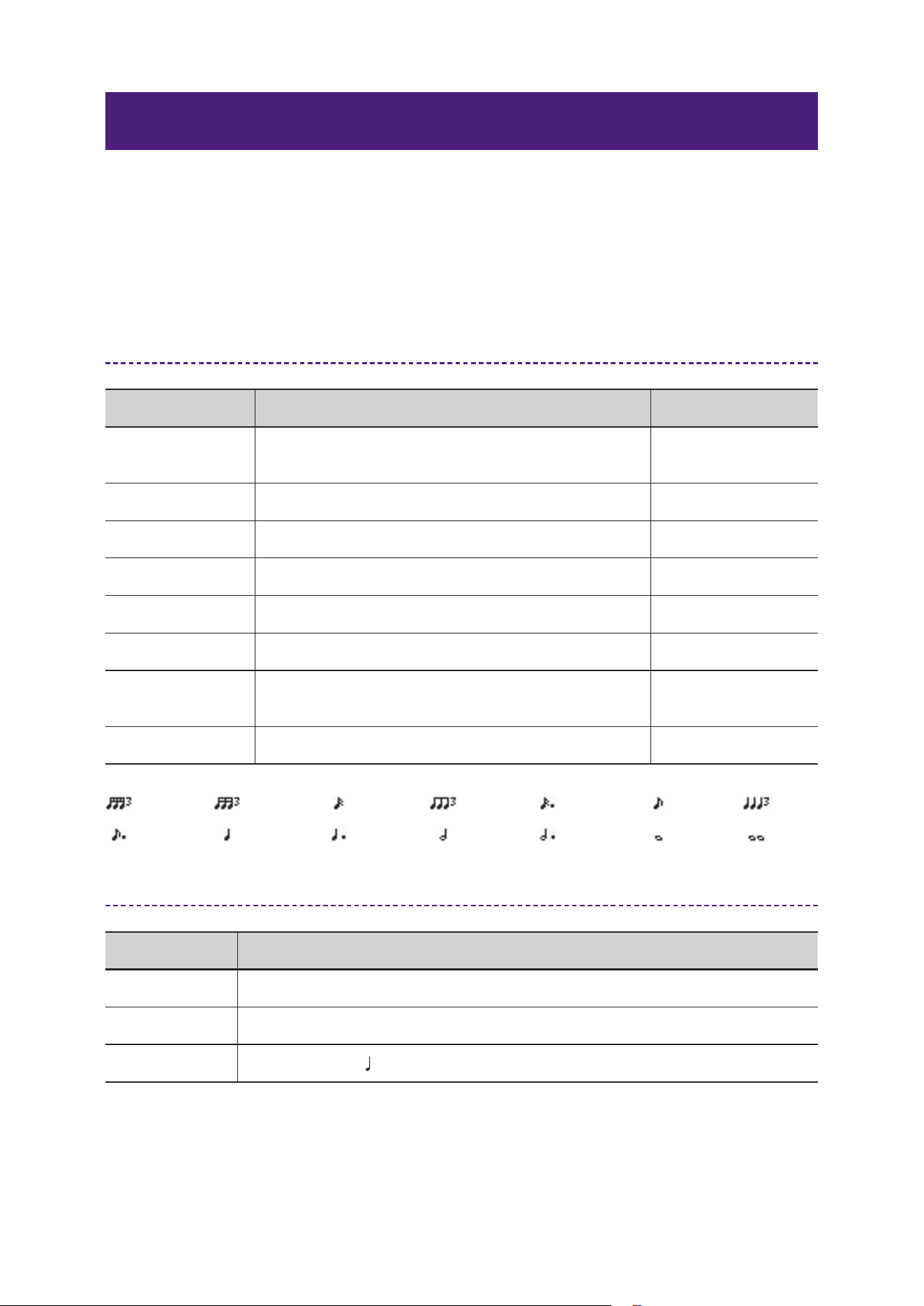
Note
Sets the delay in note units when tempo sync is
enabled.
*1
BPM Sets the tempo. 25–300
*1 Note values are calculated as follows, with the maximum value depending on the tempo setting.
Recommended Settings by Application
Application Recommended Setting Example
Vocal Delay: 240 ms / Feedback Gain: 15 / LPF: 8.5 kHz / HPF: 150 Hz
Guitar Delay: 500 ms / Feedback Gain: 20 / LPF: 10 kHz / HPF: 100 Hz
Synthesizer Sync: On / Note:
Quarter note / High Ratio: 0.6
= 1/48
= 2/1
= 1/16= 1/24 = 1/12
= 3/4= 3/16 = 1/2
= 3/32 = 1/6
= 1/4
= 1/8
= 1/1= 3/8
22
Effect Reference Guide
PING PONG DELAY
Ping Pong Delay is a stereo delay effect where the delayed sound alternates between the left and right
channels. It creates spatial width and movement, adding rhythmic depth to vocals, synths, and guitars.
Parameters
Parameter Name Description Example Range
Delay Time
Sets the delay time in milliseconds. When tempo
sync is enabled, this depends on the Note and BPM
settings.
1.0 ms–1350.0 ms
Feedback Gain Sets the amount of feedback. −99%–+99%
High Ratio Sets the amount of high–frequency feedback. 0.1–1.0
HPF Sets the cutoff frequency for the high–pass filter.
Thru, 21.2 Hz–8.00
kHz
LPF Sets the cutoff frequency for the low–pass filter.
50.0 Hz–16.0 kHz,
Thru
Sync Enables/disables tempo synchronization. On, Off
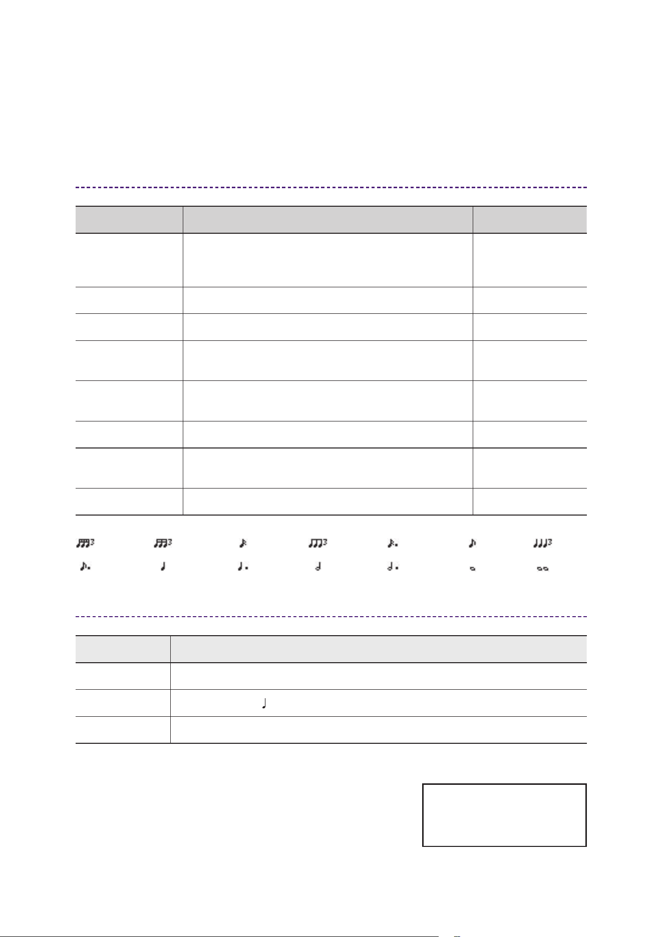
Note
Sets the delay in note units when tempo sync is
enabled.
*1
BPM Sets the tempo. 25–300
*1 Note values are calculated as follows, with the maximum value depending on the tempo setting.
= 1/48
= 2/1
= 1/16= 1/24 = 1/12
= 3/4= 3/16 = 1/2
= 3/32 = 1/6
= 1/4
= 1/8
= 1/1= 3/8
Recommended Settings by Application
Application Recommended Setting Example
Vocal Delay: 240 ms / Feedback Gain: 15 / LPF: 8.5 kHz / HPF: 150 Hz
Synthesizer Sync: On / Note:
Quarter note / High Ratio: 0.6
Guitar Delay: 500 ms / Feedback Gain: 20 / LPF: 10 kHz / HPF: 100 Hz
Yamaha Global Site
https://www.yamaha.com/
Yamaha Downloads
https://download.yamaha.com/
© 2025 Yamaha Corporation
Published 10/2025 MW-A0