Loading ...
Loading ...
Loading ...
20
51D0528
LX Series Direct Vent Gas Fireplace
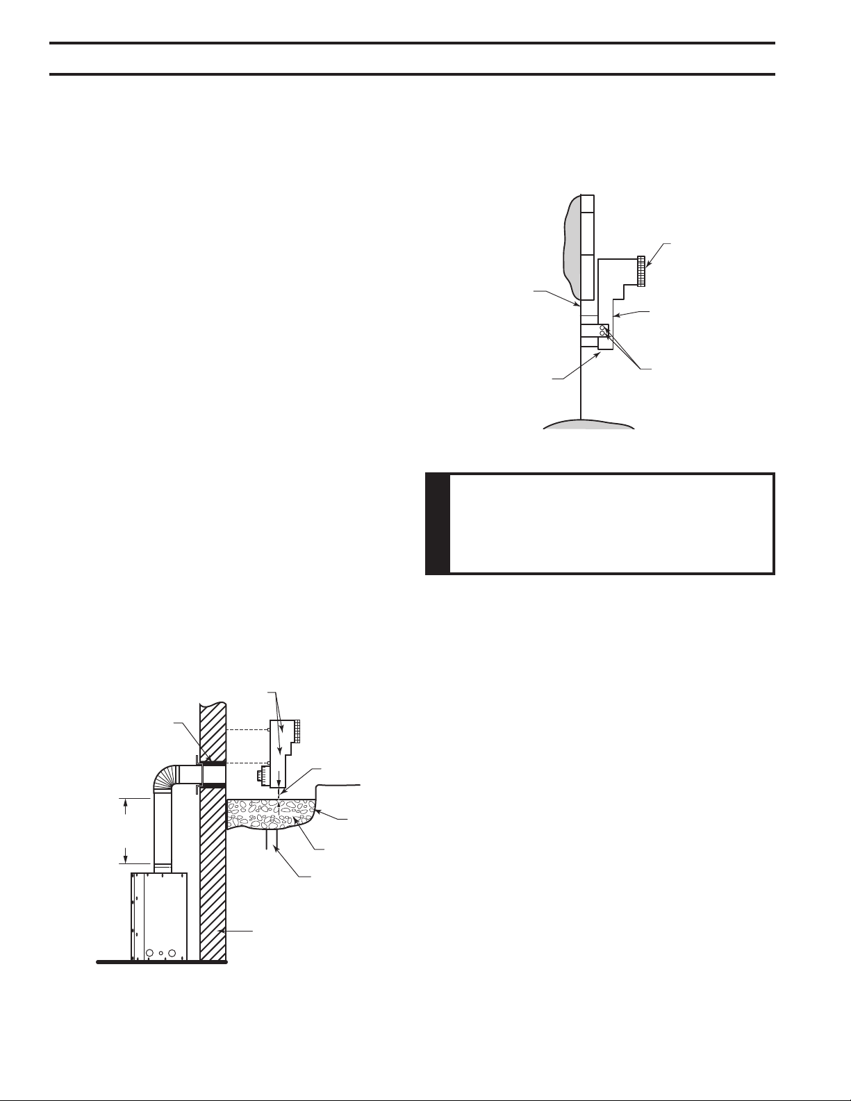
When it is not possible to meet the required vent terminal
clearances of 12" above grade level, a snorkel kit is recom-
mended. It allows installation depth down to 7" (178 mm)
below grade level. The 7" (178 mm) is measured from the
center of the horizontal vent pipe as it penetrates through
the wall.
If installing a snorkel, a minimum 24" vertical rise is neces-
sary. The maximum horizontal run with the 24” (610 mm)
vertical pipe is 36" (914 mm). This measurement is taken
from the collar of the replace (or transition elbow) to the
face of the exterior wall. See the Sidewall Venting Graph
for extended horizontal run if the vertical exceeds 24".
1. Establish vent hole through the wall. Page 17, Figure
15
2. Remove soil to a depth of approximately 16" (406 mm)
below base of snorkel. Install drain pipe. Install window
well (not supplied). Rell hole with 12" (305 mm) of
coarse gravel leaving a clearance of approximately 4"
below snorkel. Figure 25
3. Install vent system.
4. Ensure a watertight seal is made around the vent pipe
coming through the wall.
5. Apply high temperature sealant caulking (supplied)
around the 4" and 7" snorkel collars.
6. Slide the snorkel into the vent pipes and secure to the
wall.
7. Level the soil so as to maintain a 4" clearance below
snorkel. Figure 25
24”
Minimum
Figure 25 -
Below Grade Installation
Screws
Minimum
4" Clearance
Ground
Window
Well
Gravel
Drain
Foundation Wall
Firestop
FP1965
Figure 26 -
Snorkel Installation, Recessed Foundation
Foundation
Recess
Watertight Seal
Around Pipe
Sheet Metal
Screws
Snorkel
Wall Screws
FP1966
If the foundation is recessed, use recess brackets (not
supplied) for securing lower portion of the snorkel. Fasten
brackets to wall rst, then secure to snorkel with self drill-
ing #8 x 1/2 sheet metal screws. It will be necessary to
extend vent pipes out as far as the protruding wall face.
Figure 26
This Gas Fireplace has been approved for,
• Vertical installations up to 40' (12 m) in height. Up to
a 10' (3 m) horizontal vent run can be installed within
the vent system using a maximum of two 90° elbows.
Figure 27
• Install restrictor disk on vertical runs of 10' or more.
• Up to two 45° elbows may be used within the horizontal
run. For each 45° elbow used on the horizontal plane,
the maximum horizontal length must be reduced by 18"
(450 mm).
Maximum horizontal length
No elbows = 10’ (3 m)
1 x 45° elbows = 8.5’ (2.6 m)
2 x 45° elbows = 7’ (2.1 m)
• A minimum of an 8' (2.5 m) vertical rise is required.
• Two sets of 45°elbows offsets may be used within the
vertical sections. From 0 to a maximum of 8' (2.5 m) of
vent pipe can be used between elbows. Figure 28
• The maximum angular variation allowed in the system
is 270°. Figure 28
• See termination height on Page 22.
Loading ...
Loading ...
Loading ...