Installation and Operating Instructions
51D0528 8/11 Rev. 13

2
51D0528
LX Series Direct Vent Gas Fireplace
High Elevations ........................................................5
Gas Pressures .........................................................5
Gas Specications & Orice Size ............................5
Before You Start .......................................................7
Fireplace Framing ....................................................7
Fireplace Location ....................................................8
Optional Top Vent Application ................................11
Installation Precautions ..........................................12
Installation Clearances for Vent Pipe .....................13
Installation Planning ...............................................14
Horizontal Termination ...........................................14
Vertical Termination ................................................14
General Information - Termination Location ...........15
How to Use the Vent Graph ...................................16
Rear Wall Vent Installation .....................................17
Horizontal (Through the Wall) Termination ................
Conguration ..........................................................18
Below Grade Installation ........................................20
Vertical Through-the-Roof Installation ....................20
Installation for Vertical Termination ........................21
Check Gas Type.....................................................23
Install Gas Piping ...................................................23
Electrical Wiring .....................................................25
Remote Wall Switch ...............................................26
What To Do If You Smell Gas .................................34
Lighting Pilot for the First Time ..............................34
Lighting Pilot ..........................................................35
Lighting Burner .......................................................36
To Turn Off Gas ......................................................36
Venting System ......................................................37
Cleaning Glass .......................................................37
Pilot and Burner Flames ........................................37
Firebox Cleaning ....................................................37
51D0528
3
LX Series Direct Vent Gas Fireplace
4. Never install the replace
• in a recreational vehicle
• where curtains, furniture, clothing, or other am-
mable objects are less than 42" from the front, top,
or sides of the replace
• in high trafc areas
• in windy or drafty areas
5. This replace reaches high temperatures. Keep chil-
dren and adults away from hot surfaces to avoid burns
or clothing ignition. Fireplace will remain hot for a time
after shutdown. Allow surfaces to cool before touch-
ing.
6. Young children should be carefully supervised when
they are in the same room as the appliance. Toddlers,
young children and others may be susceptible to
accidental contact burns. A physical barrier is recom-
mended if there are at risk individuals in the house. To
restrict access to a replace or stove, install an adjust-
able safety gate to keep toddlers, young children and
other at risk individuals out of the room and away from
hot surfaces.
7. Do not modify replace under any circumstances. Any
parts removed for servicing must be replaced prior to
operating replace.
8. Turn replace off and let cool before servicing, install-
ing, or repairing. Only a qualied service person should
install, service, or repair the replace. Have burner
system inspected annually by a qualified service
person.
9. You must keep control compartments, burners, and
circulating air passages clean. More frequent cleaning
may be needed due to excessive lint and dust from
carpeting, bedding material, pet hair, etc. Turn off the
gas valve and pilot light before cleaning replace.
10. Have venting system inspected annually by a quali-
ed service person. If needed, have venting system
cleaned or repaired. See Cleaning and Maintenance,
Page 37.
This replace is a vented product. This replace must be
properly installed by a qualied service person. The glass
door must be properly seated and sealed. If this unit is not
properly installed by a qualied service person with glass
door properly seated and sealed, combustion leakage
can occur.
Early signs of carbon
monoxide poisoning are similar to the u with headaches,
dizziness and/or nausea. If you have these signs, the re-
place may not have been installed properly. Get fresh air
at once! Have the replace inspected and serviced by a
qualied service person. Some people are more affected
by carbon monoxide than others. These include pregnant
women, people with heart or lung disease or anemia,
those under the inuence of alcohol, and those at high
altitudes.
Propane/LP gas and natural gas are both odorless. An
odor-making agent is added to each of these gases. The
odor helps you detect a gas leak. However, the odor added
to these gases can fade. Gas may be present even though
no odor exists.
Make certain you read and understand all warnings. Keep
this manual for reference. It is your guide to safe and proper
operation of this replace.
1. This appliance is only for use with the type of gas
indicated on the rating plate. This appliance is not
convertible for use with other gases unless a certied
kit is used.
2. For propane/LP replace, do not place propane/LP
supply tank(s) inside any structure. Locate propane/
LP supply tank(s) outdoors. To prevent performance
problems, do not use propane/LP fuel tank of less than
100 lbs. capacity.
3. If you smell gas
• shut off gas supply.
• do not try to light any appliance.
• do not touch any electrical switch; do not use any
phone in your building .
• immediately call your gas supplier from a neigh-
bor’s phone. Follow the gas supplier’s instruc-
tions.
Please leave these instructions with the appliance.
Please retain these instructions for future reference
.
4
51D0528
LX Series Direct Vent Gas Fireplace
11. Keep the area around your replace clear of combus-
tible materials, gasoline, and other ammable vapor
and liquids. Do not run replace where these are used
or stored. Do not place items such as clothing or deco-
rations on or around replace.
12. Do not use this replace to cook food or burn paper or
other objects.
13. Never place anything on top of replace.
14. Do not use any solid fuels (wood, coal, paper, card-
board, etc.) in this replace. Use only the gas type
indicated on rating plate.
15. This appliance, when installed, must be electrically
grounded in accordance with local codes or in the
absence of local codes, with the National Electrical
Code, ANSI/NFPA 70, or the Canadian Electrical Code,
CSA C22.1.
16. Do not obstruct the ow of combustion and ventilation
air in any way. Provide adequate clearances around
air openings into the combustion chamber along with
adequate accessibility clearance for servicing and
proper operation.
17. When the appliance is installed directly on carpeting,
tile or other combustible material other than wood
ooring, you must set appliance on a metal or wood
panel or hearth pad extending the full width and depth
of the appliance.
18. Do not use replace if any part has been exposed to
or under water. Immediately call a qualied service
person to arrange for replacement of the unit.
19. Do not operate replace if any log is broken.
20. Do not use a blower insert, heat exchanger insert, or
any other accessory not approved for use with this
replace.
21. Do not operate the replace with glass door removed,
cracked, or broken.
22. This product
must be installed by a licensed plumber or gas tter
when installed within the Commonwealth of Massa-
chusetts. Flexline installation must not exceed 36".
Direct Vent type appliances draw all combustion air from
outside of the dwelling through the vent pipe.
These appliances have been tested by CSA and found to
comply with the established standards for DIRECT VENT
GAS FIREPLACE HEATERS in the USA and Canada as
follows:
TESTED TO:
ANSI Z21.88-2009 / CSA 2.33-2009 STANDARDS
It is normal for replaces fabricated of steel
to give off some expansion and/or contraction
noises during the start up or cool down cycle.
Similar noises are found with your furnace heat
exchanger or car engine.
It is not unusual for gas replace to give off
some odor the rst time it is burned. This is due
to the manufacturing process.
It is recommended that you burn your replace
for at least ten (10) hours the rst time you use
it. Place the fan switch in the “OFF” position
during this time.
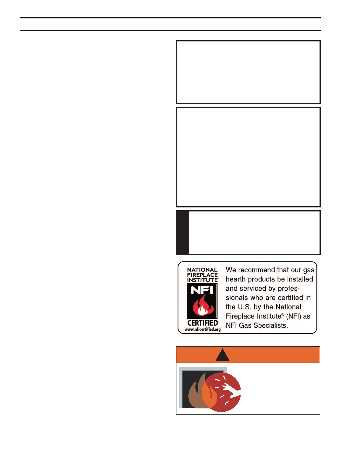
WARNING
!
HOT GLASS WILL
CAUSE BURNS.
DO NOT TOUCH GLASS
UNTIL COOLED.
NEVER ALLOW CHILDREN
TO TOUCH GLASS.
51D0528
5
LX Series Direct Vent Gas Fireplace
• This appliance has been certified for use with
either natural or propane gas. See appropriate data
plates.
• This appliance is not for use with solid fuels.
• The appliance is approved for bedroom or bedsitting
room installations.
• The appliance must be installed in accordance with
local codes if any. If none exist use the current instal-
lation code. ANSI Z223.1/NFPA 54 in the USA, CSA
B149 in Canada.
• This appliance is mobile home approved.
• The appliance must be properly connected to a vent-
ing system.
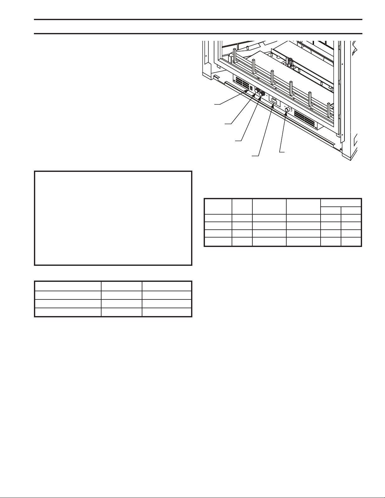
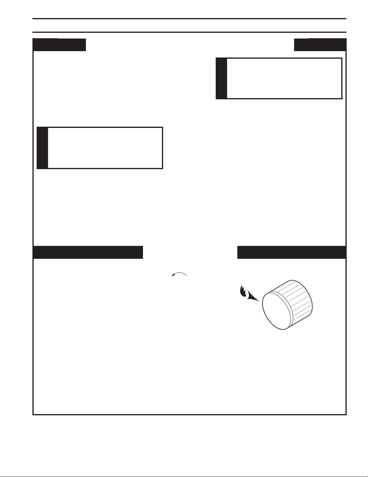
OFF
Off/Pilot/On
Knob
Optional Remote
Receiver
Figure 1 -
LXDV Fireplace Controls
Hi/Lo Knob
Blower Control
On/Off/
RS Switch
FP2710
Input ratings are shown in BTU per hour and are certi-
ed without deration for elevations up to 4,500 feet
(1,370 m) above sea level.
For elevations above 4,500 feet (1,370 m) in USA,
installations must be in accordance with the current
ANSI Z223.1/NFPA 54 and/or local codes having
jurisdiction.
In Canada, please consult provincial and/or local
authorities having jurisdiction for installations at eleva-
tions above 4,500 feet (1,370 m).
Natural Propane (LP)
Inlet Minimum 4.5” w.c. 11.0” w.c.
Inlet Maximum 10.5” w.c. 13.0” w.c.
Manifold Pressure 3.5” w.c. 10.0” w.c.
LX32NV Nat. 36,000 26,000 #46 #43
LX32PV LP 36,000 22,000 3/64" #55
LX36NV Nat. 44,000 30,000 #41 #38
LX36PV LP 44,000 32,000 #55 #53
6
51D0528
LX Series Direct Vent Gas Fireplace
Min. Rough
Opening
Depth
Min. Rough
Opening
Height
396” (1000 mm)
316M” (807 mm)
24”
(610 mm)
4056O”
(1029 mm)
Minimum
7/8” (22 mm)
for Proper Door
Operation
476”
(1210 mm)
256QE"
(71 mm)
10(6”
(276 mm)
556M”
(133 mm)
35(6”
(911 mm)
C
L
66” (168 mm) Dia.
4” (102 mm ) Dia.
106:O”
(258 mm)
41556QE” (1059 mm)
Min. Rough Opening Width
206QE” (516 mm)
1656O”
(420 mm)
216M”
(553 mm)
216M”
(553 mm)
4456M" (1124 mm)
6256O” (1588 mm)
316QE”
(792 mm)
4456M" (1124 mm)
1" (25 mm)
Spacers
Min. Rough
Opening
Depth
Min. Rough
Opening
Height
6” (1102 mm)
336M” (857 mm)
24”
(610 mm)
4056O”
(1029 mm)
Minimum
7/8” (22 mm)
for Proper Door
Operation
476”
(1210 mm)
256QE"
(71 mm)
10(6”
(276 mm)
556M”
(133 mm)
35(6”
(911 mm)
C
L
66” (168 mm) Dia.
4” (102 mm ) Dia.
126:O”
(309 mm)
45556QE” (1161 mm)
Min. Rough Opening Width
246QE” (618 mm)
16”
(406 mm)
216M”
(553 mm)
216M”
(553 mm)
47" (1194 mm)
6656O” (1689 mm)
3356O”
(851 mm)
47" (1194 mm)
1" (25 mm)
Spacers
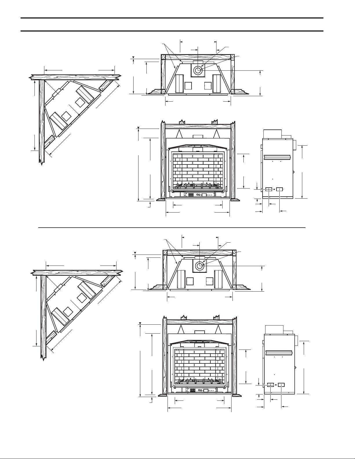
Figure 2 -
LX32 Fireplace & Framing Dimensions
Figure 3 -
LX36 Fireplace & Framing Dimensions
51D0528
7
LX Series Direct Vent Gas Fireplace
Read this homeowner manual thoroughly and follow all
instructions carefully. Inspect all contents for shipping
damage and immediately inform your dealer if any damage
is found. Do not install any unit with damaged, incomplete,
or substitute parts. Check your packing list to verify that
all listed parts have been received. You should have the
following:
• Fireplace (Firebox and Burner System)
• Log Set
• Propane Conversion Kit
• Rock Wool
• Deector Shield (to be used with Simpson Horizontal
Termination – P/N 985)
• Phillips Screwdriver • Hammer
• Saw and/or saber saw • Level
• Measuring Tape • Pipe Wrench
• Electric Drill and Bits • Tee Joint
• Pliers • Square
• Framing Materials • Wall Finishing Materials
• Piping Complying with Local Codes
• Caulking Material (Noncombustible)
• Fireplace Surround Material (Noncombustible)
• Pipe Sealant Approved for use with Propane/LPG
(Resistant to Sulfur Compounds)
Firebox framing can be built before or after the appliance
is set in place. Construct rebox framing following Figure
2 or 3. The framing headers may rest on the top of the
rebox standoffs.
The rebox may be installed directly on a combustible oor
or raised on a platform of an appropriate height. When
the rebox is installed directly on carpeting, tile, or other
combustible material, other than wood ooring, the rebox
shall be installed on a metal or wood panel extending the
full width and depth of the enclosure.
To access control door, build a platform to make the
bottom of appliance equal to or higher than top of nished
hearth extension, or elevate unit a minimum of 7/8" above
suboor.
8
51D0528
LX Series Direct Vent Gas Fireplace
Plan for the installation of your appliance. This includes
determining where the unit is to be installed, the vent con-
guration to be used, framing and nishing details, and
whether any optional accessories (i.e. blower, wall switch,
or remote control) are desired. Consult your local building
code agency to ensure compliance with local codes, includ-
ing permits and inspections.
The following factors should be taken into consideration:
• Clearance to side-wall, ceiling, woodwork, and windows.
Minimum clearances to combustibles
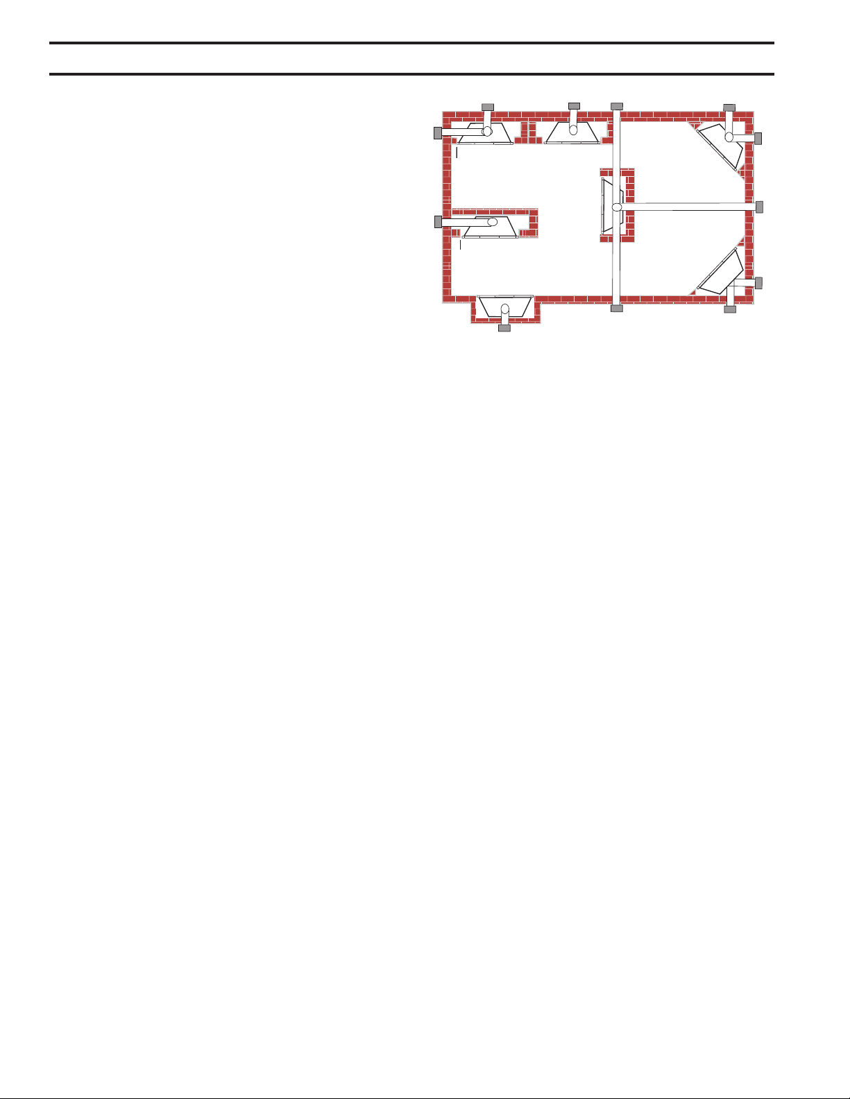
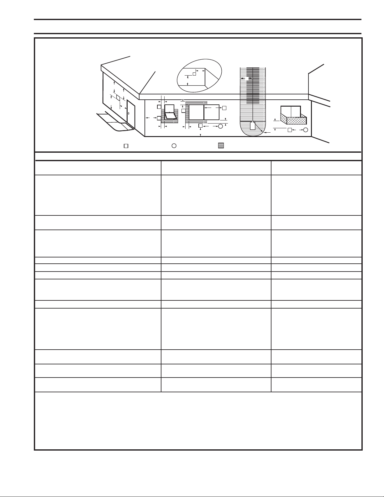
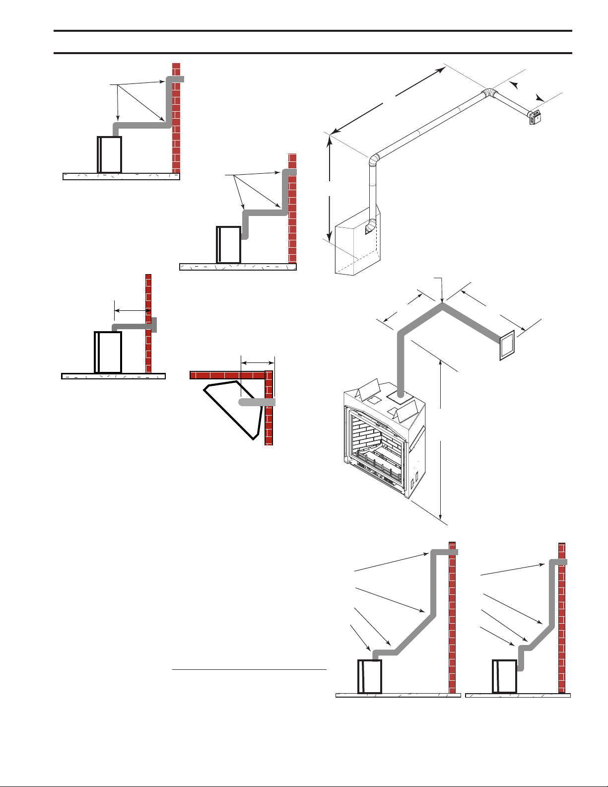
• This replace may be installed along a wall, across a
corner, or use an exterior chase. Refer to Figure 4 for
suggested locations.
• Location should be out of high trafc areas and away
from furniture and draperies due to heat from appli-
ance.
• Never obstruct the front opening of the replace.
• Do install in the vicinity where gasoline or other
ammable liquids may be stored.
• Vent pipe routing. See VENTING section found in this
manual for allowable venting congurations.
• These units can be installed in a bedroom. See National
Fuel Gas Code ANSI Z233.1/NFPA 54 — (current
edition), the Uniform Mechanical Code — (current edi-
tion), and Local Building Codes for specic installation
requirements.
Y
E
A
B
C
D
F
Y
B
X
Figure 4 -
Locating Gas Fireplace
** Island (C) and room divider (D) installation is possible as long
as the horizontal portion of vent system (X) does not exceed
20'. See Installing Horizontal Termination Conguration on
Pages 20 and 21.
* When you install your replace in (D) room divider or (E)
at on wall corner positions (Y), a minimum of 6" clearance
must be maintained from perpendicular wall and front of
replace.
A Flat on Wall
B Cross Corner
C Island**
D Room Divider*
E Flat on Wall Corner*
F Chase Installation
Y 9" Minimum
51D0528
9
LX Series Direct Vent Gas Fireplace
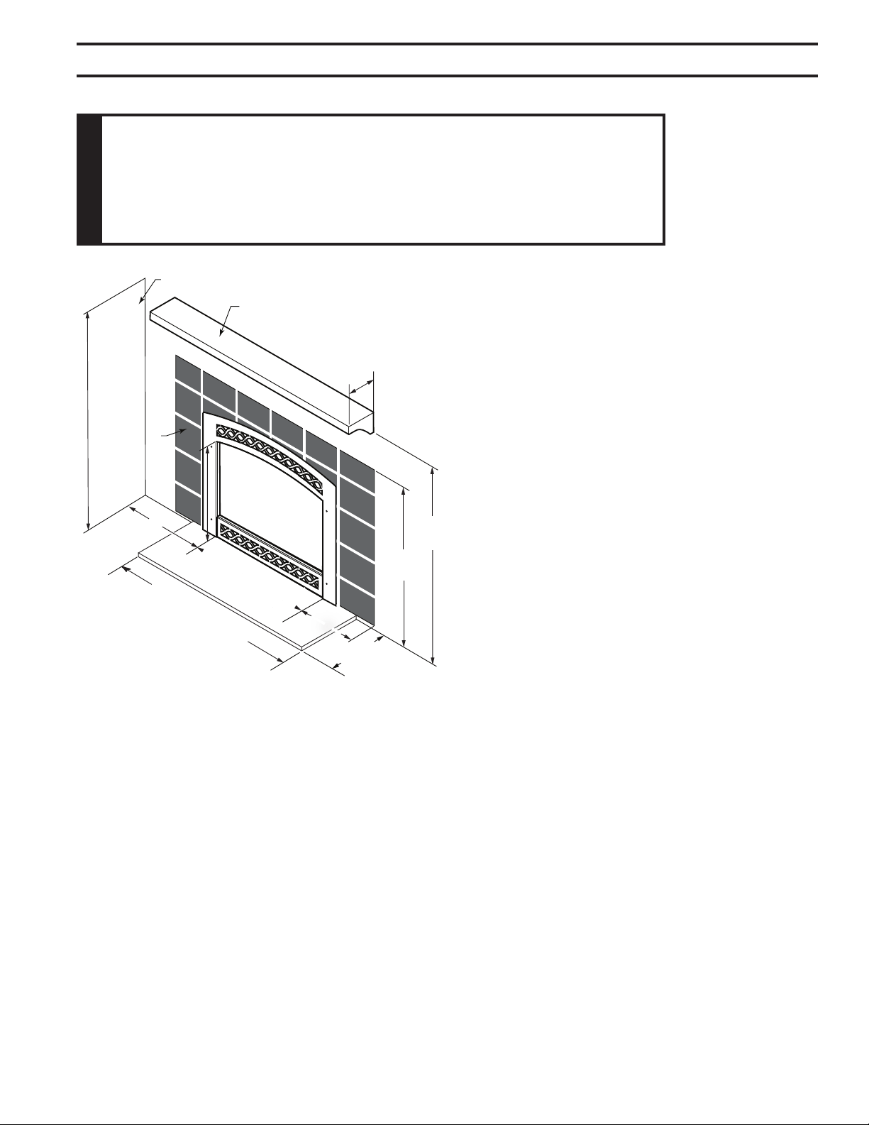
12” (305 mm)
Max. Depth
9” (229 mm)
Minimum
LX32 - 39” (991 mm)
LX36 - 43” (1092 mm)
LX32 - 30” (762 mm)
LX36 - 34” (864 mm)
6”
(152 mm)
12” (305 mm)
Minimum
466M”
(1187 mm)
446M”
(1137 mm)
Side Wall
Ceiling
Combustible
Mantel
Noncombus-
tible Facing
FP2711
Figure 5 -
Clearances to Combustible
Materials
The replace must be installed on a non-combustible hearth
extending a minimum of 12" from the replace opening
(local codes may require a larger hearth). The hearth must
also extend to both sides of the face (see the table above
for the exact width of the face).
10
51D0528
LX Series Direct Vent Gas Fireplace
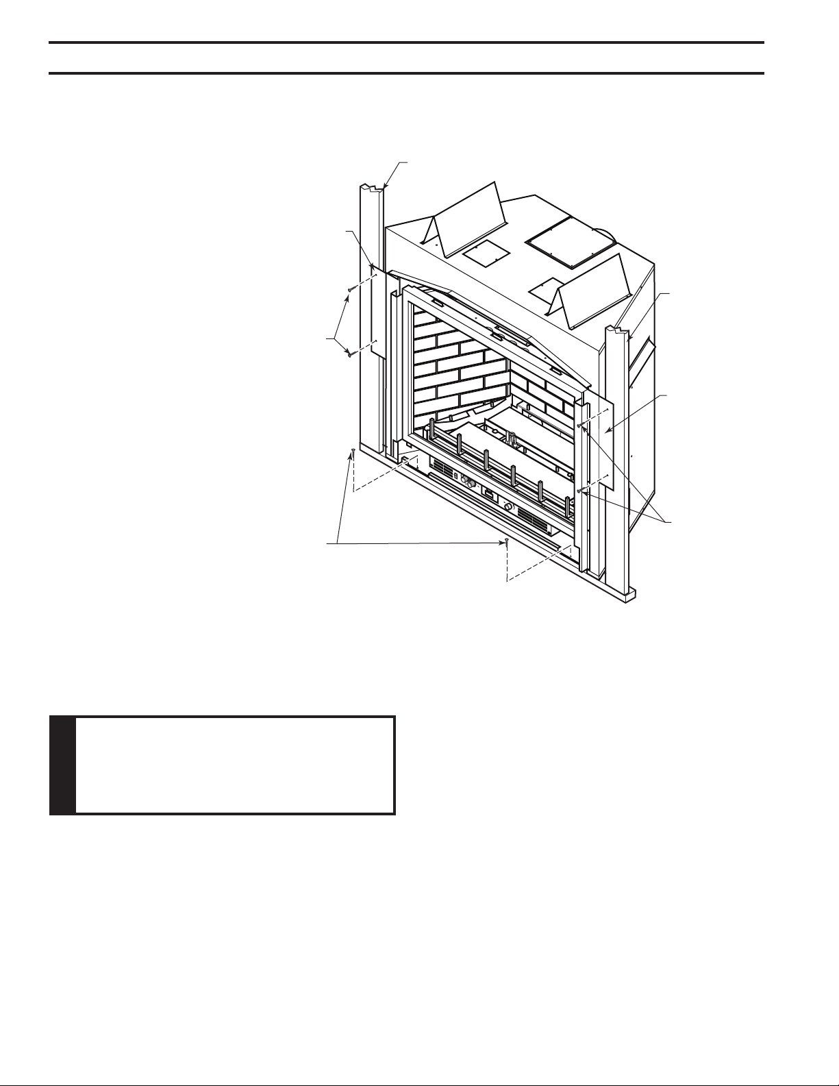
The replace must be secured to the oor and/or to framing studs as shown in Figure 6. Use two
(2) wood screws or masonry/ concrete screws to secure replace to the oor. Use four (4) screws
to attach replace to framing. The side brackets are adjustable from 1/2" to 5/8" to accommodate
different thickness of noncombustible material.
OFF
Figure 6 -
Securing Fireplace to Floor and Framing Studs
Framing
Framing
Adjustable
Bracket
Adjustable
Bracket
Screws
Screws
Screws
FP2712
Any remote wiring (i.e. remote control, wall switch, and optional fan) must be done prior to
nal nishing to avoid costly reconstruction.
Only noncombustible materials (i.e. brick, tile, slate, steel, or other materials with a UL re rating
of Zero) may be used to cover the black surface of the appliance. A 300°F minimum adhesive may
be used to attach facing materials to the black surface. If joints between the nished wall and the
replace surround are sealed, a 300°F minimum sealant material (General Electric RTV103 or
equivalent) must be used.
51D0528
11
LX Series Direct Vent Gas Fireplace
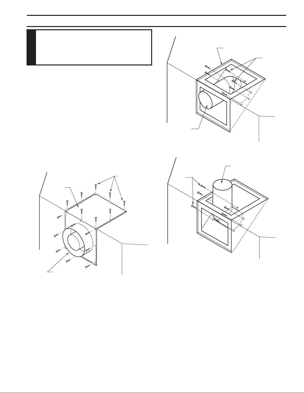
The appliance is shipped as a rear vent unit. If the installa-
tion layout requires the unit to be a top vent conguration
the appliance can be converted by the following steps.
When removing and retting the plates and adapter be
sure the associated gaskets are undamaged and retted
as required.
1. Remove the eight (8) screws securing the ue pipe
adapter to the replace body. Figure 7
2. Set the ue pipe adapter aside, complete with the
gasket. Do not damage the gaskets as the adapter and
gasket must be retted.
3. Remove the eight (8) screws securing the ue pipe cover
to the top of the intake box and remove the cover and
gasket. Figure 7
Flue Pipe
Cover
Flue Pipe
Adapter
Screws
FP1991
Figure 7 -
Remove 16 Screws from Flue Pipe
Adapter and Flue Pipe Cover
4. Remove eight (8) screws securing the ue pipe to the
back of the intake box and remove the pipe and gasket.
Figure 8
5. Replace ue pipe to top of rebox. Ensure the gasket is
in place and undamaged. Secure with eight (8) screws.
Figure 9
6. Place the ue pipe cover and gasket removed in step
3 over the ue opening in bottom of the intake box.
B\,
Figure 8 -
Remove Flue Pipe
Screws
Flue Cover
Flue Pipe
FP1992
Figure 9 -
Attach Flue Pipe to Top
Vent Congurations
Flue Pipe
Screws
FP1993
7. Ret the ue pipe adapter and gasket to the top of re-
place. Secure the adapter with eight (8) screws removed
in Step 1.
12
51D0528
LX Series Direct Vent Gas Fireplace
Consult local building codes before beginning the installation. The installer must make sure to select
the proper vent system for installation. Before installing vent kit, the installer must read this replace
manual and vent kit instructions.
Only a qualied installer/service person should install venting system. The installer must follow
these safety rules:
• Wear gloves and safety glasses for protection.
• Use extreme caution when using ladders or when on rooftops.
• Be aware of electrical wiring locations in walls and ceilings.
The following actions will void the warranty on your venting system:
• Installation of any damaged venting component.
• Unauthorized modication of the venting system.
• Installation of any component part not manufactured or approved by MHSC.
• Installation other than permitted by these instructions.
51D0528
13
LX Series Direct Vent Gas Fireplace
until the ue penetrates the outside wall.
1"
*3"
**1"
**1"
35(6”
(911 mm)
Figure 10 -
Combustible Clearances for Vent Pipe
* A minimum of 3" clearance to the top is
required along horizontal length until ue pipe
penetrates outside wall.
** A minimum 1" clearance to combustibles
permitted all around ue at outside wall
FP2713
14
51D0528
LX Series Direct Vent Gas Fireplace
There are two basic types of direct-vent installation:
• Horizontal Termination
• Vertical Termination
It is important to select the proper length of vent pipe for the
type of termination you choose. It is also important to note
the wall thickness.
Select the amount of vertical rise desired. All horizontal run of venting must have minimum 1/4" rise
for every 12" of run towards the termination.
You may use up to three 90° elbows in this vent conguration. Refer to Horizontal (Through the
Wall) Termination Congurations on Page 18.
Measure the distance from the replace oor to the ceiling. Add the ceiling thickness, the vertical
rise in an attic or second story, and allow for sufcient vent height above the roof line.
You may use two 45° elbows in place of a 90° elbow. You must follow rise to run ratios when
using 45° elbows. The appliance is approved for use with three 90° elbows maximum or a combina-
tion of 90° and 45° elbows up to a maximum of 270°.
For two-story applications, restops are required at each oor level. If an offset is needed in the
attic, additional pipe and elbows will be required.
You may use a chase with a vent termination with exposed pipe on the exterior of the house. See
Installing Vent System in a Chase below. If pipe is enclosed in chase, it is not exposed.
It is very important that the venting system maintain its balance between the combustion air intake and
the ue gas exhaust. Certain limitations apply to vent congurations and must be strictly followed.
A chase is a vertical boxlike structure built to enclose venting that runs along the outside of a build-
ing. A chase is required for such venting.
51D0528
15
LX Series Direct Vent Gas Fireplace
V
V
V
V
V
V
V
X
X
X
D
E
B
B
B
C
B
M
B
A
J
K
F
L
VENT TERMINATION AIR SUPPLY INLET
AREA WHERE TERMINAL IS NOT PERMITTED
H
I
Fixed
Closed
Operable
Operable
Fixed
Closed
V
B
INSIDE
CORNER DETAIL
V
A
G
CFM145a
A = Clearance above grade, veranda, porch, 12” (30 cm) 12” (30 cm)
deck, or balcony
B = Clearance to window or door that may be 6” (15 cm) for appliances 6” (15 cm) for appliances
opened < 10,000BTU/h (3kW), 12” (30 cm) < 10,000 BTU/h (3kW), 9”
for appliances > 10,000 Btuh (3kW) and (23 cm) for appliances > 10,000
< 100,000 BTU/h (30kW), 36” (91 cm) Btuh (3kW) and < 50,000 BTU/h
for appliances > 100,000 BTU/h (30kW) (15kW), 12” (30 cm) for
appliances > 50,000 BTU/h(15kW)
C = Clearance to permanently closed window 12” (305 mm) recommended to 12” (305 mm) recommended to
prevent window condensation prevent window condensation
D = Vertical clearance to ventilated soft located
above the terminal within a horizontal 18” (458 mm) 18” (458 mm)
distance of 2’ (610mm) from the center
line of the terminal
E = Clearance to unventilated soft 12” (305 mm) 12” (305 mm)
F = Clearance to outside corner see next page see next page
G = Clearance to inside corner (see next page) see next page see next page
H = Clearance to each inside of center line 3’ (91 cm) within a height of 15’ (5 m) 3’ (91 cm) within a height of 15’
extended above meter/regulator assembly above the meter/regulator assembly (5 m) above the meter/regulator
assy
I = Clearance to service regulator vent outlet 3’ (91 cm) 3’ (91 cm)
J = Clearance to nonmechanical air supply inlet 6” (15 cm) for appliances < 10,000 6” (15 cm) for appliances
to building or the combustion air inlet to any BTU/h (3kW), 12” (30 cm) for < 10,000 BTU/h (3kW), 9”
other appliances appliances > 10,000 BTU/h (3kW) and (23 cm) for appliances > 10,000
< 100,000 Btuh (30kW), 36” (91 cm) BTU/h (3kW) and < 50,000 BTU/h
for appliances > 100,000 BTU/h (30kW) (15kW), 12” (30 cm) for
appliances > 50,000 BTU/h(15kW)
K = Clearance to a mechanical air supply inlet 6’ (1.83 m) 3’ (91 cm) above if within 10'
(3 m) horizontally
L = Clearance above paved sidewalk or paved 7’ (2.13 m)† 7’ (2.13 m)†
driveway located on public property
M = Clearance under veranda, porch, deck or 12” (30 cm) 12” (30cm)
balcony
1 In accordance with the current CSA-B149 Installation Codes
2 In accordance with the current ANSI Z223.1/NFPA 54 National Fuel
Gas Codes
† A vent shall not terminate directly above a sidewalk or paved
driveway which is located between two single family
dwellings and serves both dwellings
only permitted if veranda, porch, deck or balcony is fully open on a
minimum 2 sides beneath the oor:
NOTE: 1. Local codes or regulations may require different
clearances.
2. The special venting system used on Direct Vent Fireplaces
are certied as part of the appliance, with clearances
tested and approved by the listing agency.
3. MHSC assumes no responsibility for the improper
performance of the appliance when the venting system
does not meet these requirements.
Figure 11 -
Horizontal Vent Termina-
tion Locations
16
51D0528
LX Series Direct Vent Gas Fireplace
40
38
36
34
32
30
28
26
24
22
20
18
16
14
12
10
8
6
4
2
2 4 6 8 10 12 14 16 18 20
eg: A
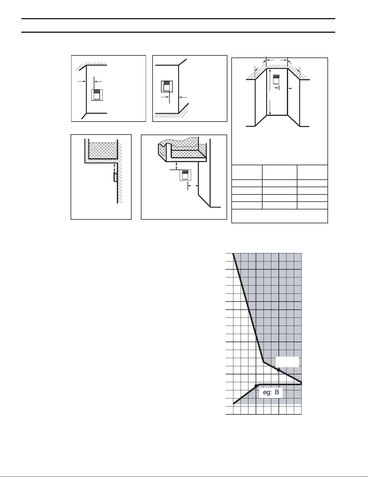
The Vent Graph should be read in conjunction with the
following vent installation instructions to determine the
relationship between the vertical and horizontal dimensions
of the vent system.
1. Determine the height of the center of the horizontal vent
pipe exiting through the outer wall. Using this dimension
on the Sidewall Vent Graph, locate the point intersecting
with the slanted graph line.
2. From the point of this intersection, draw a vertical line
to the bottom of the graph.
3. Select the indicated dimension, and position the re-
place in accordance with same.
If the vertical dimension from the oor of the
replace is 11' (3.4 m) the horizontal run to the face of
the outer wall must not exceed 14' (4.3 m).
If the vertical dimension from the oor of the
unit is 7’ (2.14 m), the horizontal run to the face of the
outer wall must not exceed 8Z\x' (2.6 m).
Sidewall Vent Graph showing the relationship between
vertical and horizontal dimensions for a Direct Vent ue
system.
Figure 13 -
Rear Wall Venting Graph
Horizontal Dimension From the Outside Face of the Wall
to the Back of the Fireplace
Vertical Dimension From the Floor of Unit to the Center of the
Horizontal Vent Pipe
Dimensions in
Feet
Outside Corner
Inside Corner
Termination Clearances
Termination clearances for buildings with combustible and noncombustible exteriors.
G =
Combustible
6" (152 mm)
Noncombustible
2" (51 mm)
F =
Combustible
6" (152 mm)
Noncombustible
2" (51 mm)
G
Balcony -
with no side wall
M =
Combustible &
Noncombustible
12" (305 mm)
M
Balcony -
with perpendicular side wall
M = 24" (610 mm)
P = 20” (508 mm)
M
F
Alcove Applications*
C
D
C
E
V
V
Combustible &
Noncombustible
V
V
V
E = Min. 6” (152 mm) for
non-vinyl sidewalls
Min. 12” (305 mm) for
vinyl sidewalls
O = 8’ (2.4 m) Min.
O
P
Figure 12 -
Allowable
Venting
584-15
No.
of Caps DMin. CMax.
1 3’ (914 mm) 2 x DActual
2 6’ (1.8 m) 1 x DActual
3 9’ (2.7 m) 2/3 x DActual
4 12’ (3.7 m) 1/2 x DActual
DMin. = # of Termination caps x 3
CMax. = (2 / # termination caps) x DActual
Termination in an alcove space (spaces open only on one side and with an overhang) is permitted with the dimensions specied for vinyl or
non-vinyl siding and softs. 1. There must be a 3’ (914 mm) minimum between termination caps. 2. All mechanical air intakes within 10’ (1 m) of a
termination cap must be a minimum of 3’ (914 mm) below the termination cap. 3. All gravity air intakes within 3’ (914 mm) of a termination cap must
be a minimum of 1’ (305 mm) below the termination cap.
51D0528
17
LX Series Direct Vent Gas Fireplace
When installed as a rear vent unit this appliance may be
vented directly to a termination located on the rear outside
termination behind the appliance
• 45° elbows may only be attached to rear when used to
direct the ue skyward (to achieve additional rise). Do
not attach 45° elbows to rear of appliance in which the
ue turns either left or right and terminates horizontal.
• The maximum horizontal distance between the rear
of the appliance and the outside face of the outside
termination is 20" (508 m). Figure 15
20”
(508 mm)
Max.
Figure 14 -
Rear Vent Application,
Maximum Horizontal Distance
FP1188
1. Locate and cut the vent opening in the wall. For com-
bustible walls rst frame in opening. Figure 15
Cut a 11Z\x"H x 9Z\x" W (292 x 24
mm) hole through the exterior wall and frame as shown.
Figure 15
Hole opening should be 7Z\x"
(190 mm) in diameter.
9Z\x"
(241 mm)
11Z\x"
(292 mm)
Fireplace Hearth
Framing Detail
7Z\x"
(190 mm)
Fireplace Hearth
VO584-100
Figure 15 -
Locate Vent Opening on Wall
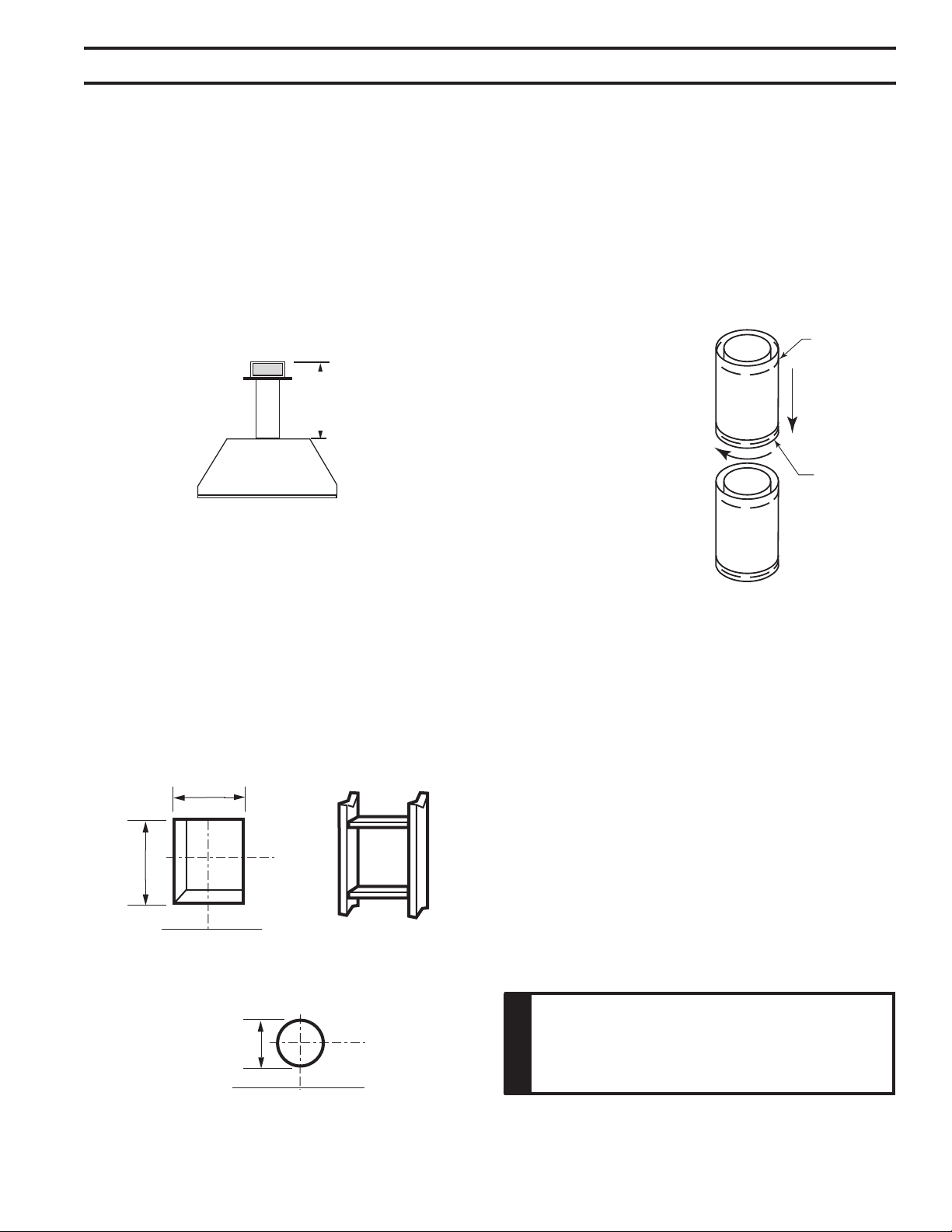
Figure 16 -
Rigid Vent Pipe Connections
Female
Locking Lugs
Male Slots
FP1953
2. Rigid vent pipes and ttings have special twist-lock
connections. Assemble the desired combination of pipe
and elbows to the appliance adaptor with pipe seams
oriented towards the wall or oor.
Twist-lock Procedure: The female ends of the pipes
and ttings have three locking lugs (indentations).
These lugs will slide straight into matching slots on
the male end of adjacent pipes and ttings. Push the
pipe sections together and twist one section clockwise
approximately one-quarter turn until the sections are
fully locked. Figure 16
3. Attach vent pipe assembly to the replace. Set replace
in front of its permanent location to insure minimum
clearances. Mark the wall for a 11Z\x"H x 9Z\x"W (292 x 24
mm) rectangle hole (for noncombustible material such
as masonry block or concrete, a 7Z\x" [190 mm] diameter
hole is acceptable). Figure 15. The center of the hole
should line up with the center line of the horizontal rigid
vent pipe end. Be sure to allow for minimum rise. Cut
a 11Z\x" x 9Z\x" (292 X 241 mm) rectangle hole through
combustible exterior wall (7Z\x" [190 mm] diameter hole
if noncombustible). Frame as necessary. Allow 1/4"
minimum rise per foot. Figure 15
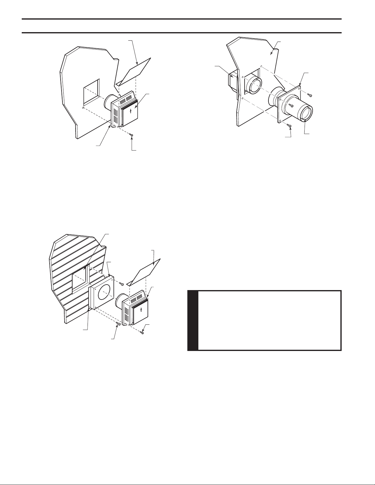
4. Apply a bead of non-hardening mastic around the
outside edge of vent cap. Position the vent cap in the
center of hole on the exterior wall with the word “UP”
on the vent cap facing up. Insure proper clearance of
1" to combustibles is maintained. Attach the vent cap
with four wood screws supplied. Figure 17
Replace the wood screws with appropriate fasteners
for stucco, brick, concrete, or other types of siding.
18
51D0528
LX Series Direct Vent Gas Fireplace
HOT
Figure 17 -
Installing Horizontal Vent Cap
Vent Cap
Apply Mastic to
All Four Sides
Deecting Shield
Wood Screw
FP2715
For vinyl siding, stucco, or wood exterior use vinyl siding
standoffs between vent cap and exterior wall. The vinyl
siding standoff prevents excessive heat from melting the
vinyl siding material. Bolt the vent cap to the standoff. Apply
non-hardening mastic around outside edge of the standoff
instead of the vent cap assembly. Use wood screws pro-
vided to attach the standoff. Figure 18
HOT
Figure 18 -
Install Vinyl Siding Standoff
Apply Mastic to
All Four Sides
Cut Vinyl Siding Away
to Fit Standoff
Wood Screw
Vent
Cap
Screw
Standoff
Deecting Shield
FP2716
Figure 19 -
Connect Vent Cap with Horizontal Vent Pipe
Interior Wall
Surface
Fire Stop
Assembly
Horizontal
Vent Pipe
Screw
Vent Cap
(Horizontal
Termination)
FP1957
The Vent Graph, showing the relationship between vertical
and horizontal side wall venting, will help to determine the
various dimensions allowable. Refer to Page 16
When vent termination exits through foundations less than
20" below siding outcrop, the vent pipe must ush up with
the siding.
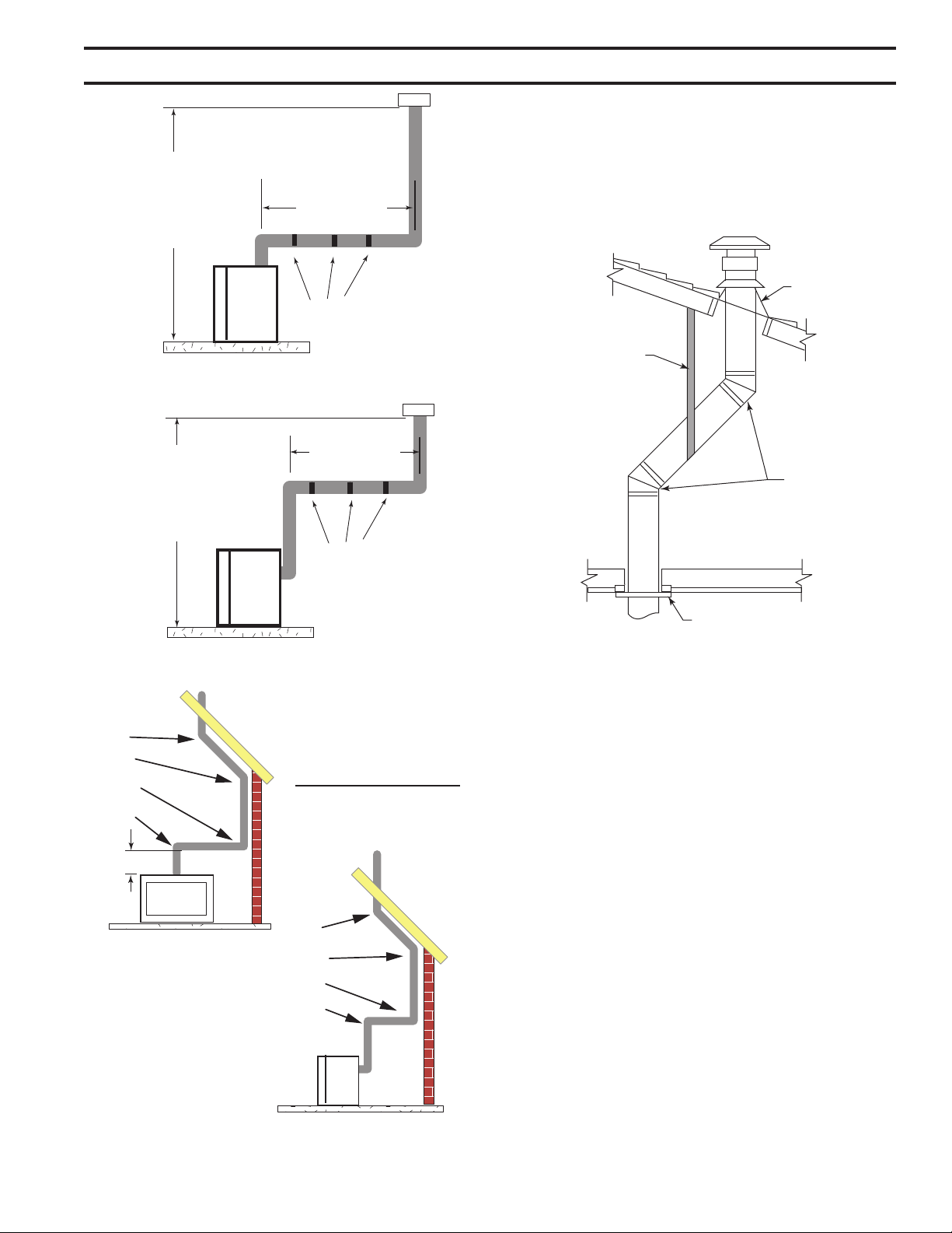
It is best to locate the replace in such a way that minimizes
the number of offsets and horizontal vent length.
The horizontal vent run refers to the total length of vent
pipe from the ue collar of the replace (or the top of the
Transition Elbow) to the face of the outer wall.
• The maximum number of 90° elbows per side wall
installation is three (3). Figure 20
• If a 90° elbow is tted directly on top of the replace
ange the maximum horizontal vent run before the ter-
mination or a vertical rise is 36” (914 mm). Figure 21
• If a 90° elbow is used in the horizontal vent run (level
height maintained) the horizontal vent length is reduced
by 36" (914 mm). This does not apply if the 90° elbows
are used to increase or redirect a vertical rise. Figure
23
5. Slide re stop over the vent pipe before connecting the
horizontal run to the vent cap. Figure 19
6. The pipe overlap should be a minimum of 1Z\v". Apply
silicone to the outer pipe connection. Fasten all vent
connections with screws provided.
7. Slide re stop against the interior wall surface and attach
with screws. Figure 19
51D0528
19
LX Series Direct Vent Gas Fireplace
Figure 20 -
Maximum Three (3) 90° Elbows
Per Installation
3 x 90°
Elbows
3 x 90°
Elbows
FP1176
36"
(914 mm)
Max.
36"
(914 mm)
Max.
Figure 21 -
Maximum Horizontal Run with No Rise
FP1177
According to the vent graph (Page 16) the
maximum horizontal vent length in a system with a 7.5'
vertical rise is 20’ (6 m). If a 90° elbow is required in the
horizontal vent it must be reduced to 17' (5.2 m).
In Figures 22 and 23, Dimension A plus B must not be
greater than 17' (5.2 m).
• For each 45° elbow installed in the horizontal run, the
length of the horizontal run MUST be reduced by 18"
(457 mm). This does not apply if the 45° elbows are
installed on the vertical part of the vent system.
• The maximum number of elbow degrees in a system is
270°. Figure 24
A: 10’
B: 7’
7’6”
Figure 22 -
Maximum Vent Run with Elbows
Horizontal 90° Elbow = 3' Reduction
FP1959
A + B = 17' Maximum
90°
A
B
7’6”
(2.3 m)
Figure 23 -
Horizontal Run Reduction
FP2717
Elbow 1 = 90°
Elbow 2 = 45°
Elbow 3 = 45°
Elbow 4 = 90°
Total Angular Variation = 270°
Figure 24 -
Maximum Elbow Usage
1
2
3
4
1
2
3
4
20
51D0528
LX Series Direct Vent Gas Fireplace
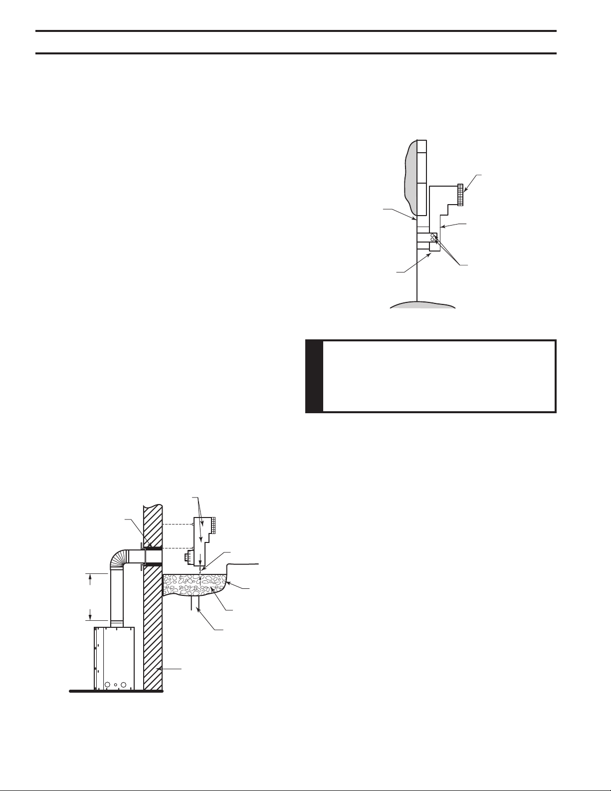
When it is not possible to meet the required vent terminal
clearances of 12" above grade level, a snorkel kit is recom-
mended. It allows installation depth down to 7" (178 mm)
below grade level. The 7" (178 mm) is measured from the
center of the horizontal vent pipe as it penetrates through
the wall.
If installing a snorkel, a minimum 24" vertical rise is neces-
sary. The maximum horizontal run with the 24” (610 mm)
vertical pipe is 36" (914 mm). This measurement is taken
from the collar of the replace (or transition elbow) to the
face of the exterior wall. See the Sidewall Venting Graph
for extended horizontal run if the vertical exceeds 24".
1. Establish vent hole through the wall. Page 17, Figure
15
2. Remove soil to a depth of approximately 16" (406 mm)
below base of snorkel. Install drain pipe. Install window
well (not supplied). Rell hole with 12" (305 mm) of
coarse gravel leaving a clearance of approximately 4"
below snorkel. Figure 25
3. Install vent system.
4. Ensure a watertight seal is made around the vent pipe
coming through the wall.
5. Apply high temperature sealant caulking (supplied)
around the 4" and 7" snorkel collars.
6. Slide the snorkel into the vent pipes and secure to the
wall.
7. Level the soil so as to maintain a 4" clearance below
snorkel. Figure 25
24”
Minimum
Figure 25 -
Below Grade Installation
Screws
Minimum
4" Clearance
Ground
Window
Well
Gravel
Drain
Foundation Wall
Firestop
FP1965
Figure 26 -
Snorkel Installation, Recessed Foundation
Foundation
Recess
Watertight Seal
Around Pipe
Sheet Metal
Screws
Snorkel
Wall Screws
FP1966
If the foundation is recessed, use recess brackets (not
supplied) for securing lower portion of the snorkel. Fasten
brackets to wall rst, then secure to snorkel with self drill-
ing #8 x 1/2 sheet metal screws. It will be necessary to
extend vent pipes out as far as the protruding wall face.
Figure 26
This Gas Fireplace has been approved for,
• Vertical installations up to 40' (12 m) in height. Up to
a 10' (3 m) horizontal vent run can be installed within
the vent system using a maximum of two 90° elbows.
Figure 27
• Install restrictor disk on vertical runs of 10' or more.
• Up to two 45° elbows may be used within the horizontal
run. For each 45° elbow used on the horizontal plane,
the maximum horizontal length must be reduced by 18"
(450 mm).
Maximum horizontal length
No elbows = 10’ (3 m)
1 x 45° elbows = 8.5’ (2.6 m)
2 x 45° elbows = 7’ (2.1 m)
• A minimum of an 8' (2.5 m) vertical rise is required.
• Two sets of 45°elbows offsets may be used within the
vertical sections. From 0 to a maximum of 8' (2.5 m) of
vent pipe can be used between elbows. Figure 28
• The maximum angular variation allowed in the system
is 270°. Figure 28
• See termination height on Page 22.
51D0528
21
LX Series Direct Vent Gas Fireplace
10' Maximum
40'
Maximum
Height
8'
Minimum
Height
Support
Straps
Every 5'
Vertical
Support Straps Every 3'
10' Maximum
40'
Maximum
Height
8'
Minimum
Height
Support Straps Every 3'
FP1183
Figure 27 -
Support Straps for Horizontal Runs
1
2
3
4
1
2
3
4
Example: Elbow 1 = 90°
Elbow 2 = 45°
Elbow 3 = 45°
Elbow 4 = 90°
Total Angular = 270°
Variation
FP1179
Figure 28 -
Maximum Elbow Usage
1. Determine the route your vertical venting will take. If
ceiling joist, roof rafters or other framing will obstruct the
venting system, consider an offset. Figure 29 to avoid
cutting load bearing members.
Figure 29 -
Offset with Wall Strap and 45° Elbows
Roof Flashing
Wall Strap
45° Elbows
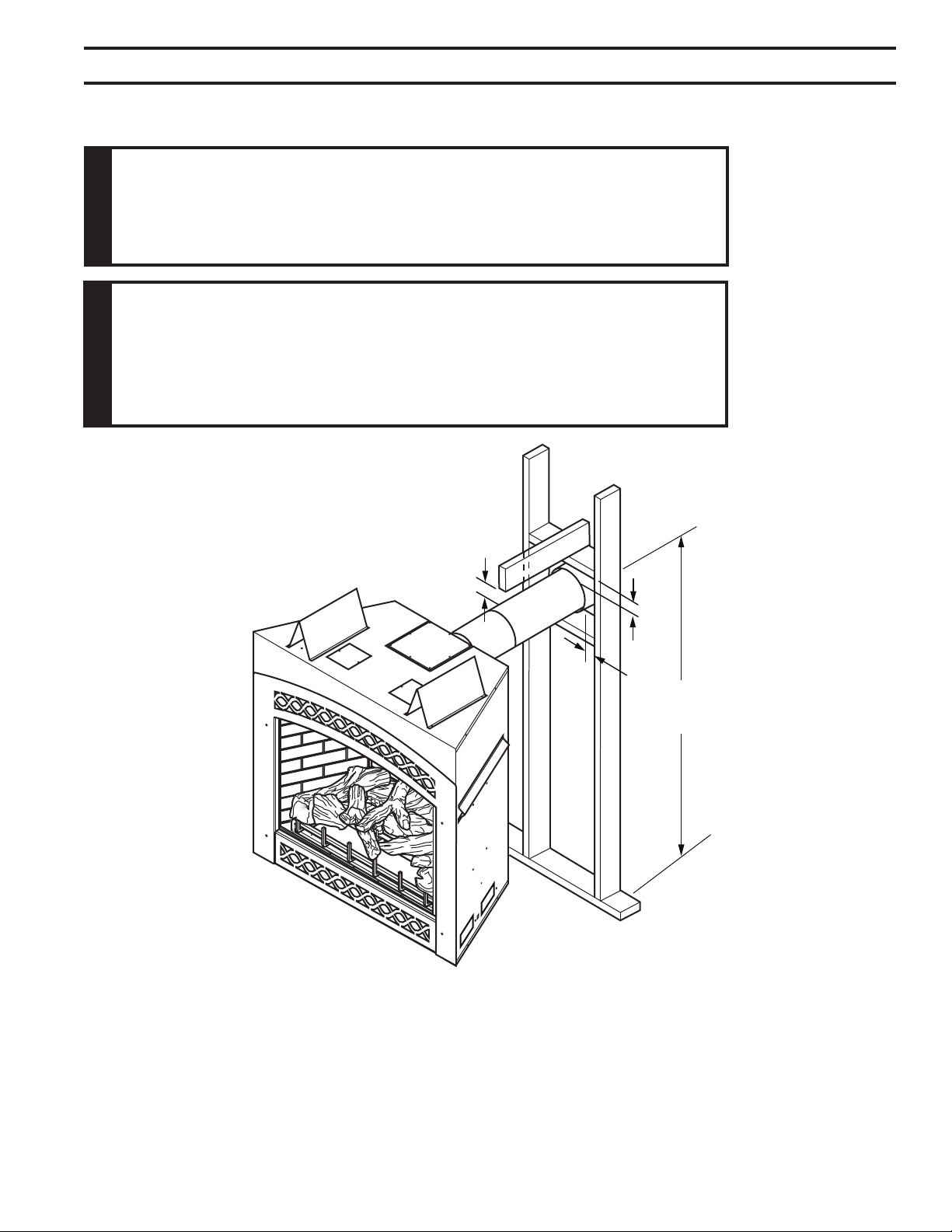
Ceiling Firestop
FP1669
Pay special attention to these installation instructions
for required clearances (air space) to combustibles when
passing through ceilings, walls, roofs, enclosures, attic
rafters, etc. Do not pack air spaces with insulation. Also
note maximum vertical rise of the venting system and any
maximum horizontal offset limitations. Offsets must fall
within the parameters shows on Page 16, Figure 13.
2. Set replace in desired location. Drop a plumb line down
from the ceiling to the position of the ue exit. Mark the
center point where the vent will penetrate the ceiling.
Drill a small locating hole a this point.
Drop a plumb line from the inside of the roof to the ceiling
locating hole in the ceiling. Mark the center point where
the vent will penetrate the roof. Drill a small locating hole
at this point.
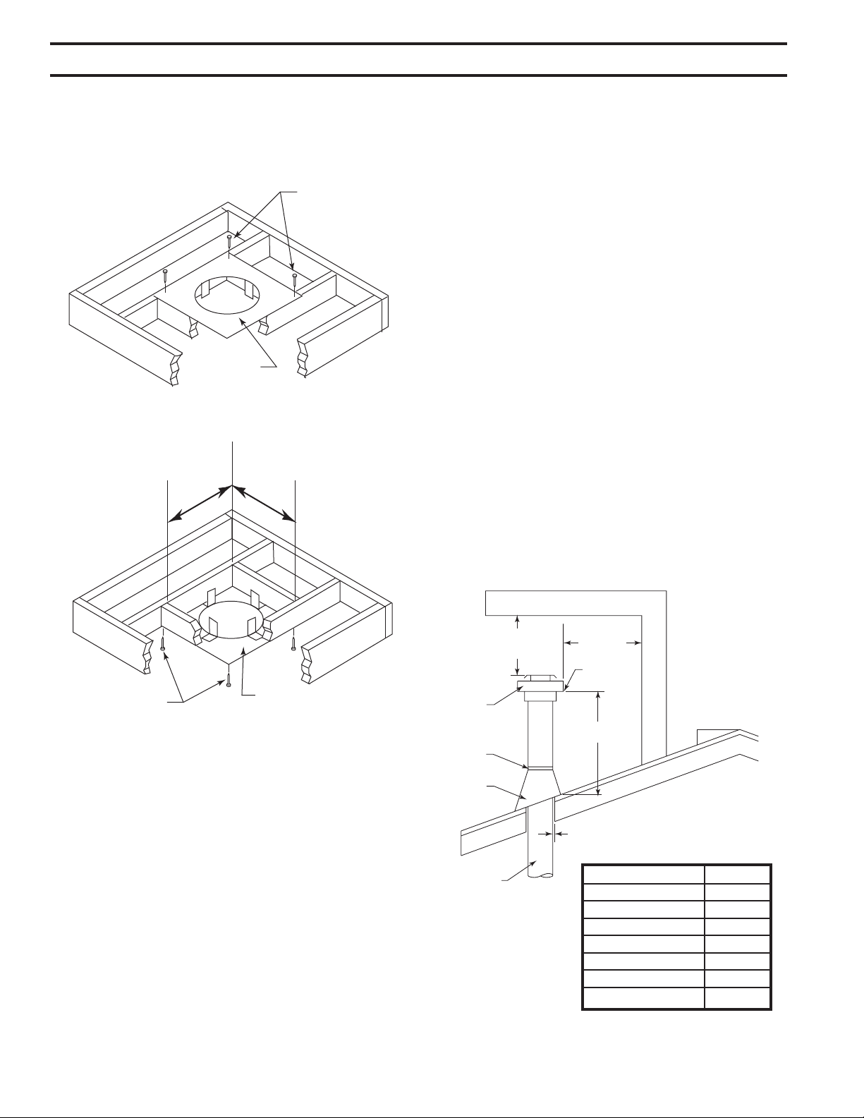
1. Cut a 9Z\x" (241 mm) square hole in the ceiling using the
locating hole as a center point The opening should be
framed to 9Z\x" x 9Z\x" (241 x 241 mm) inside dimensions
as shown in Figure 31 using framing lumber the same
size as the ceiling joist. If the area above the ceiling is
an insulated ceiling or a room, nail restop from the top
22
51D0528
LX Series Direct Vent Gas Fireplace
side. This prevents loose insulation from falling into the
required clearance space. Figure 30. Otherwise, install
restop below the framed hole. The restop should be
installed with no less than three nails per side. Figure
35.
Figure 30 -
If area above is a room, install restop above framed
hole as shown
Firestop
Nails
FP1969
9
1
/
2
"
9
1
/
2
"
Figure 31 -
If area above is not a room, install restop below
framed hole as shown
Nails
Firestop
FP1970
2. Assemble the desired lengths of pipe and elbows nec-
essary to reach from the burner system ue up through
the restop. Be sure pipe and elbow connections are
fully twist-locked. Page 17, Figure 16
3. Cut a hole in the roof using the locating hole as a center
point. (Cover any exposed open vent pipes before cut-
ting hole in roof). The 9Z\x" x 9Z\x" (241 x 241 mm) hole
must be measured on the horizontal. Actual length may
be larger depending on the pitch of the roof. There must
be a 1" minimum clearance from the vent pipe to com-
bustible materials. (Insulation should be considered a
combustible material) Frame the opening as shown on
Page 17, Figure 15.
4. Connect a section of pipe and extend up through the
hole.
If an offset is needed to avoid obstructions, you
must support the vent pipe every three (3) feet. Use wall
straps for this purpose. Refer to Figures 27 & 29. Whenever
possible, use 45° elbows instead of 90° elbows. The 45°
elbow offers less restriction to the ow of the ue gases
and intake air.
5. Place the ashing over the pipe section(s) extending
through the roof. Secure the base of the ashing to
the roof and framing with roong nails. Be sure roong
material overlaps the top edge of the ashing. There
must be a 1" clearance from the vent pipe to combustible
materials.
6. Continue to add pipe sections until the height of the vent
cap meets the minimum requirements below.
You must increase vent height for steep roof
pitches. Nearby trees, adjoining roof lines, steep pitched
roofs, and other similar factors may cause poor draft or
down-drafting in high winds. Increasing the vent height
may solve this problem.
If the vent pipe passes through any occupied areas
above the rst oor, including storage spaces and closets,
you must enclose pipe. You may frame and sheetrock the
enclosure with standard construction material. Make sure
to meet the minimum allowable clearances to combustibles.
Do not ll any of the required clearance spaces with
insulation.
2 ft.
Min.
2 ft. Min.
X
12
H*
Termination
Vent
Storm
Collar
Flashing
Lowest
Discharge
Opening
Concentric
Vent Pipe
1” Minimum Clearance to
Combustibles
FP1971
Horizontal Overhang
Figure 32 -
Minimum Chimney
Clearance
Flat to 6/12 1.0
Over 6/12 to 7/12 1.25
Over 7/12 to 8/12 1.5
Over 8/12 to 9/12 2.0
Over 9/12 to 10/12 2.5
Over 10/12 to 11/12 3.25
Over 11/12 to 12/12 4.0
*H - Minimum height from roof to
lowest discharge opening of vent
51D0528
23
LX Series Direct Vent Gas Fireplace
Use proper gas type for the replace you are installing. If you have conicting gas type, do not install
replace. See dealer where you purchased the replace for proper replace according to your gas
type.
When using copper or ex connectors use only ttings
approved for gas connections. The gas control inlet is
3/8" NPT.
Before installing replace and burner system, make sure you have the items listed below.
• External regulator • Piping (check local codes) • Sealant (resistant to propane/LP gas)
(supplied by installer) • Test gauge connection* • Sediment trap (recommended)
• Equipment shutoff valve* • Tee joint • Pipe wrench
• approved exible gas line with gas connector (if allowed by local codes — not provided)
* A CSA design-certied equipment shutoff valve with 1/8" NPT tap is an acceptable alternative to test gauge
connection. Purchase the CSA design-certied equipment shutoff valve from your dealer.
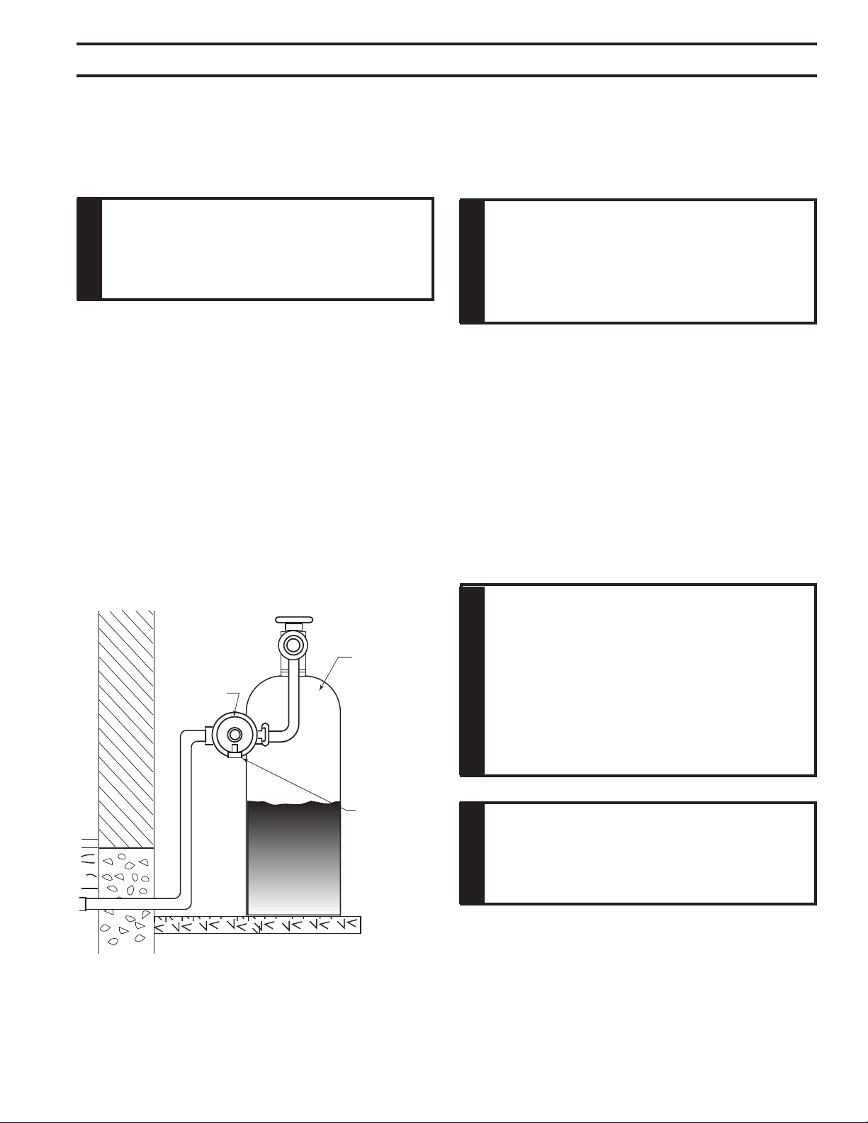
For propane/LP connections only, the installer must supply an external regulator. The external regulator will reduce
incoming gas pressure. You must reduce incoming gas pressure to between 11 and 13 inches of water. If you do not
reduce incoming gas pressure, burner system regulator damage could occur. Install external regulator with the vent
pointing down as shown in Figure 33. Pointing the vent down protects it from freezing rain or sleet.
External
Regulator
100 gal. (min)
Propane/LP
Supply Tank
Vent Pointing
Down
Figure 33 -
External Regulator with Vent Pointing Down
(Propane/LP Only)
FP1977
24
51D0528
LX Series Direct Vent Gas Fireplace
The gas line connection may be made using 1/2" rigid tubing or an approved ex connector.
Since some municipalities have additional local codes it is always best to consult your local authorities
and the current edition of the National Fuel Gas Code ANSI.Z223.1, NFPA54. In Canada CSA-B149 (1
or 2) Installation Code.
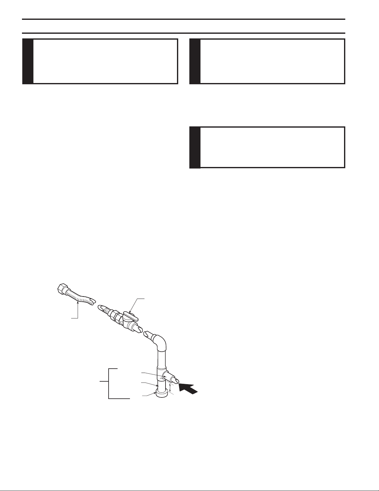
A listed manual shutoff valve must be installed upstream of
the appliance. Union tee and plugged 1/8" NPT pressure
tapping point should be installed upstream of the appliance.
Figure 34
Install main gas valve (equipment shutoff valve)
in an accessible location. The main gas valve is for turning on
or shutting off the gas to the replace.
Check your building codes for any special requirements for locating equipment shutoff valve to re-
places.
Apply pipe joint sealant lightly to male threads. This will prevent excess sealant from going into pipe.
Excess sealant in pipe could result in clogged burner system valves.
We recommend that you install a sediment trap/drip leg in supply line as shown in Figure 34. Locate
sediment trap/drip leg where it is within reach for cleaning. Install in piping system between fuel supply
and burner system. Locate sediment trap/drip leg where trapped matter is not likely to freeze. A sediment
trap traps moisture and contaminants. This keeps them from going into the burner system gas controls.
If sediment trap/drip leg is not installed or is installed wrong, burner system may not run properly.
Figure 34
3" Minimum
Pipe Nipple
Cap
Figure 34 -
Gas Connection
Tee Joint
Approved Flexible
Gas Line
CSA Design-Certied Equipment Shutoff Valve
with 1/8" NPT Tap*
Sediment Trap/Drip Leg
From Gas Meter
(5.0" w.c. to 10.5" w.c. Pressure)
From External Regulator
(11" w.c. to 13" w.c. Pressure)
51D0528
25
LX Series Direct Vent Gas Fireplace
1. Check gas type. The gas supply must be the same as
stated on the appliance’s rating decal. If the gas supply
is different from the replace, Do not install the
appliance. Contact your dealer immediately.
2. To ease installation, a 30" (mm) ex line with manual
shut-off valve has been provided with on this appli-
ance. Install and attach 1/2" gas line onto shut-off
valve.
3. After completing gas line connection, purge air from
gas line and test all gas joints from the gas meter
to the replace for leaks. Use a solution of 50/40
water and soap or a gas sniffer.
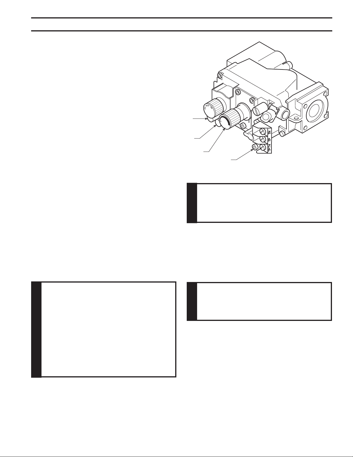
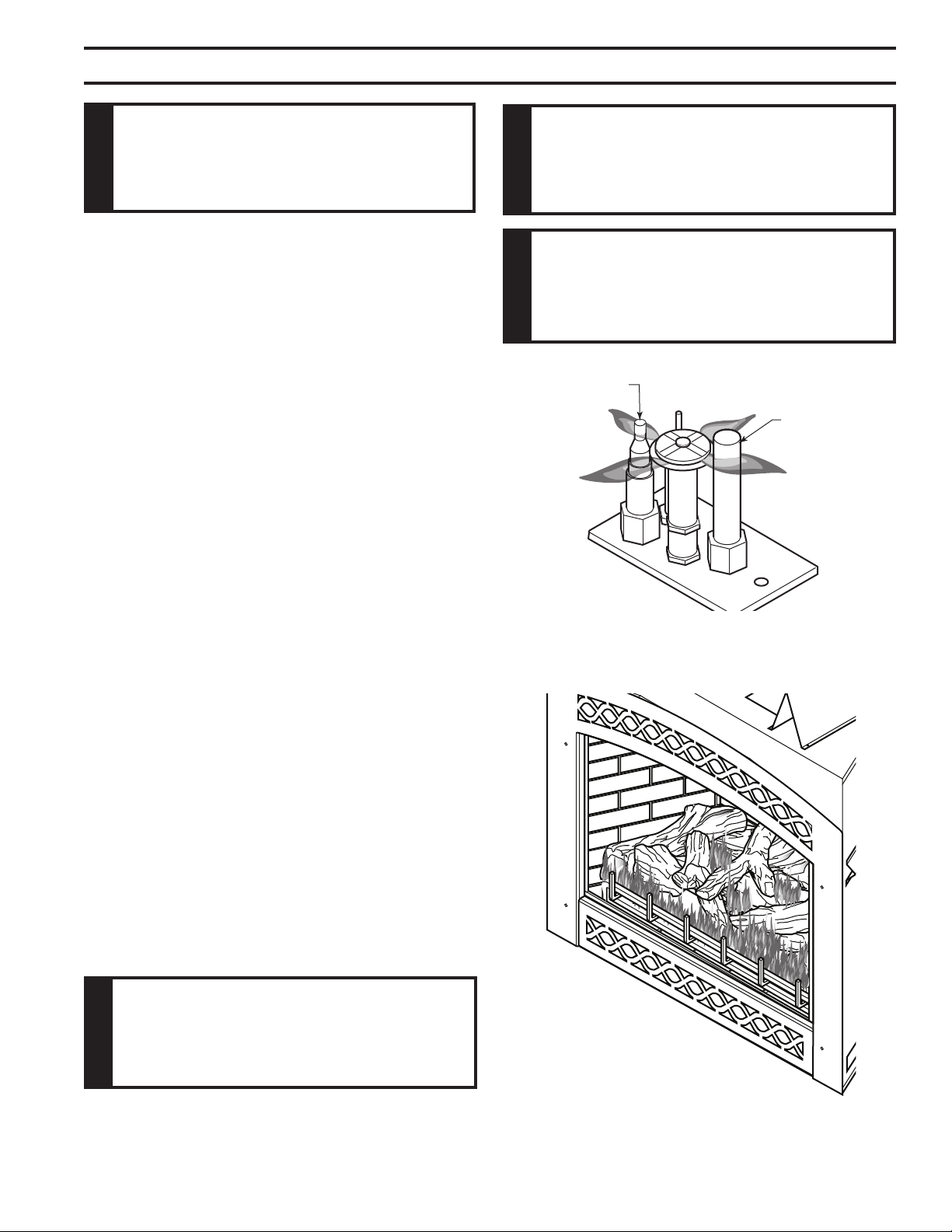
4. To adjust ame height, turn HI/LO knob to HI to get
maximum pressure to burner. Turn HI/LO knob to
LO to get minimum pressure.
5. To check gas pressures at valve, turn captured
screw counter clockwise 2 or 3 turns and then place
tubing to pressure gauge over test point. Turn unit
to high. Figure 35. After taking pressure reading,
be sure and turn captured screw clockwise rmly
to reseal. Do not over torque. Check test points for
gas leaks.
FP1979
Figure 35 -
Gas Pressure Check at Gas Valve
Pressure
Test “IN”
Pressure
Test “OUT”
HI/LO Knob
Pilot Adjustment Screw
This replace will work without any electrical supply. Elec-
tricity is only needed to operate blower.
If installed in mobile home, replace must be bolted
securely to oor.
Verify proper operation after servicing.
26
51D0528
LX Series Direct Vent Gas Fireplace
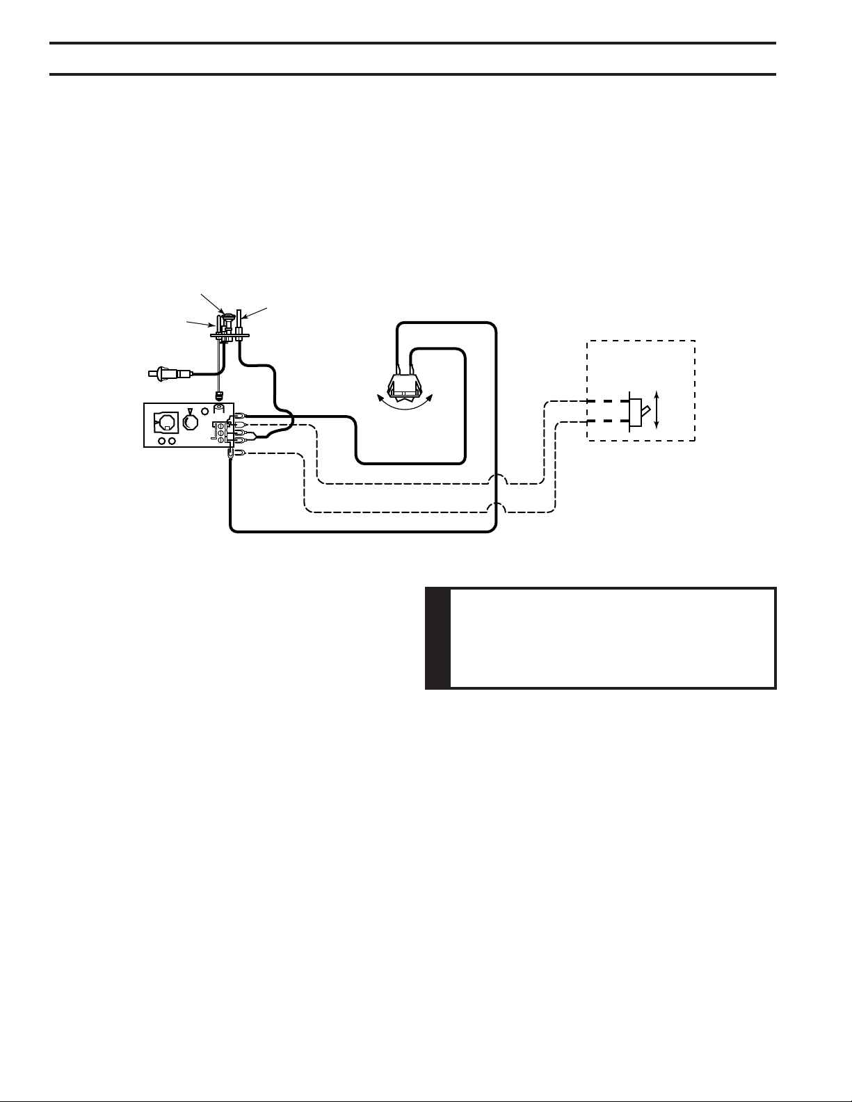
A remote wall switch and up to fteen (15) feet of 18 Ga. wire may be used with this appliance.
Attach the wall switch in a junction box at the desired location on the wall. Figure 36. Do not extend
beyond the wall switch wire length provided.
Figure 36 -
Wiring Diagram for Wall Switch
PILOT HI
LO
ON
OFF
Piezo
Ignitor
Thermocouple
Sparker
Thermopile
Pilot
Assembly
Switch
ON
OFF
Millivolt
Valve
ON
OFF
Optional 15’
Wall Switch
FP2919
51D0528
27
LX Series Direct Vent Gas Fireplace
OFF
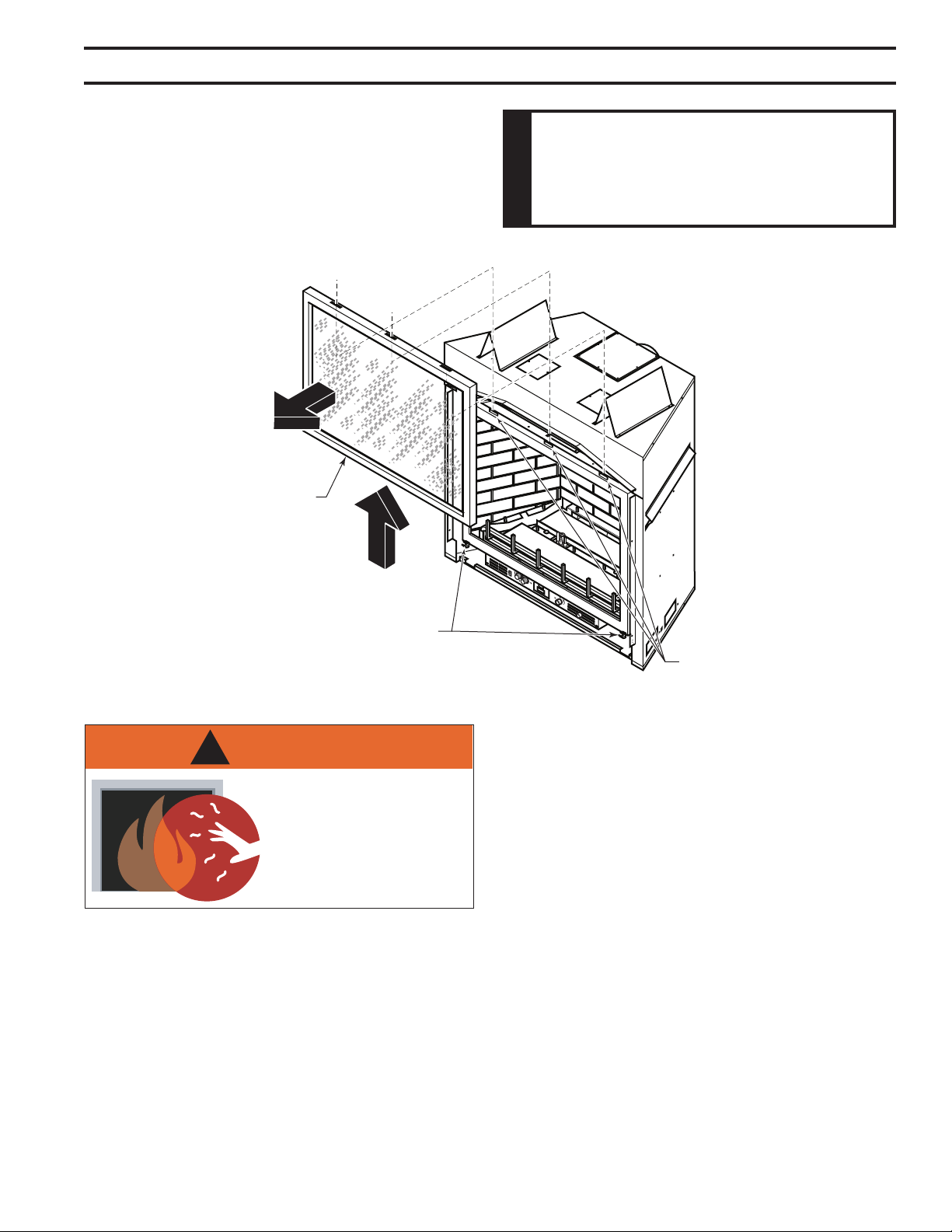
1. Release two clamps on bottom of replace. Figure 37
2. Tilt glass frame out and lift glass frame up until it clears
three tabs on top of replace.
3. Set glass frame aside.
Figure 37 -
Remove Glass Frame
Glass Frame
Three
Tabs
Clamps
WARNING
!
HOT GLASS WILL
CAUSE BURNS.
DO NOT TOUCH GLASS
UNTIL COOLED.
NEVER ALLOW CHILDREN
TO TOUCH GLASS.
28
51D0528
LX Series Direct Vent Gas Fireplace
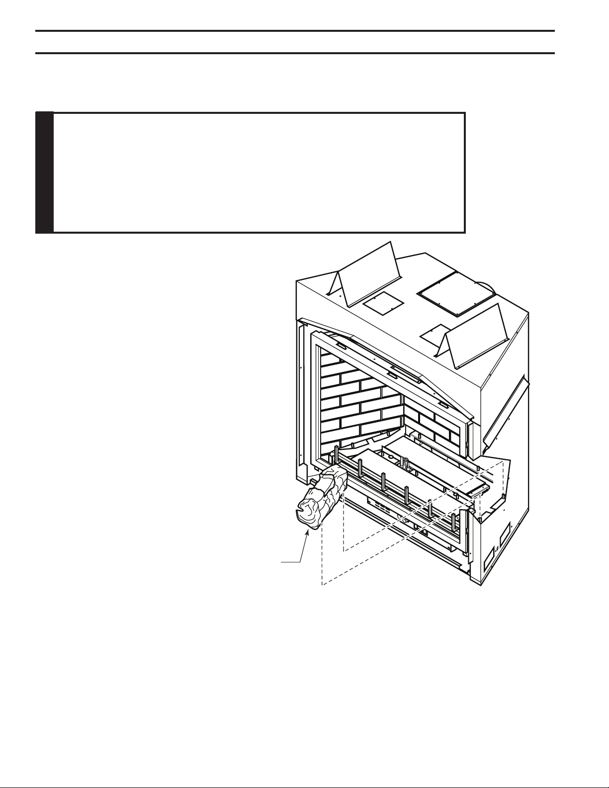
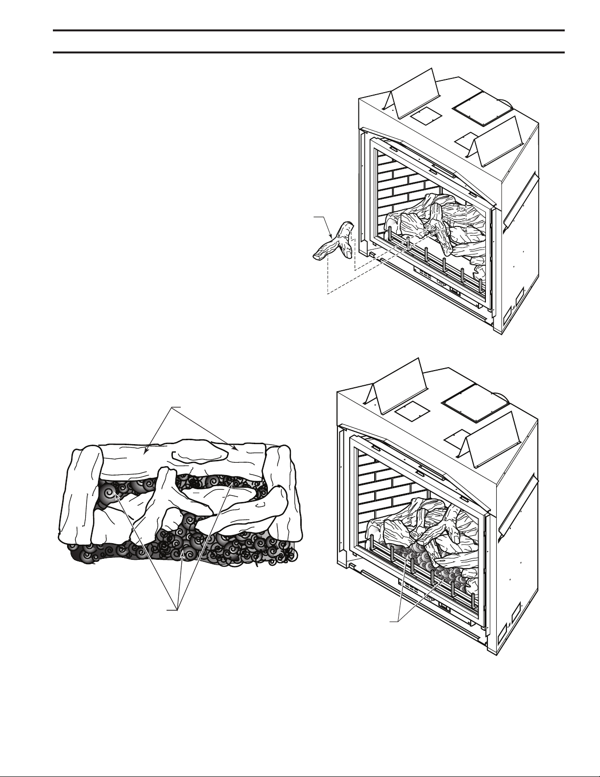
1. Carefully remove logs from wrapping.
2. Remove glass frame. Refer to Glass Frame Removal,
Page 27
— This unit is supplied with eight ceramic ber logs. Do not handle these logs
with your bare hands. After
handling the logs, wash your hands gently with soap and water to remove any traces of bers.
Bottom Right Log
#3
LG805
Figure 38
3. Place bottom right log (#3) on
two pins against right side of
rebox. Figure 38
51D0528
29
LX Series Direct Vent Gas Fireplace
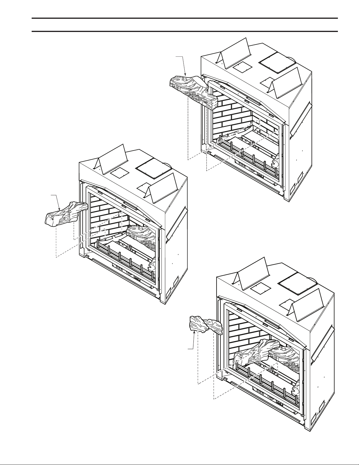
4. Place rear log (#1) on two pins against back
side of rebox. Figure 39
Rear Log #1
LG804
Figure 39
Bottom Left
Log #2
LG803
Figure 40
5. Place bottom left log (#2)
on two pins against left
side of rebox. Figure 40
Left Mid
Log #6
LG808
Figure 41
6. Place left mid log (#6) on two left
pins on burner assembly. Figure
41
30
51D0528
LX Series Direct Vent Gas Fireplace
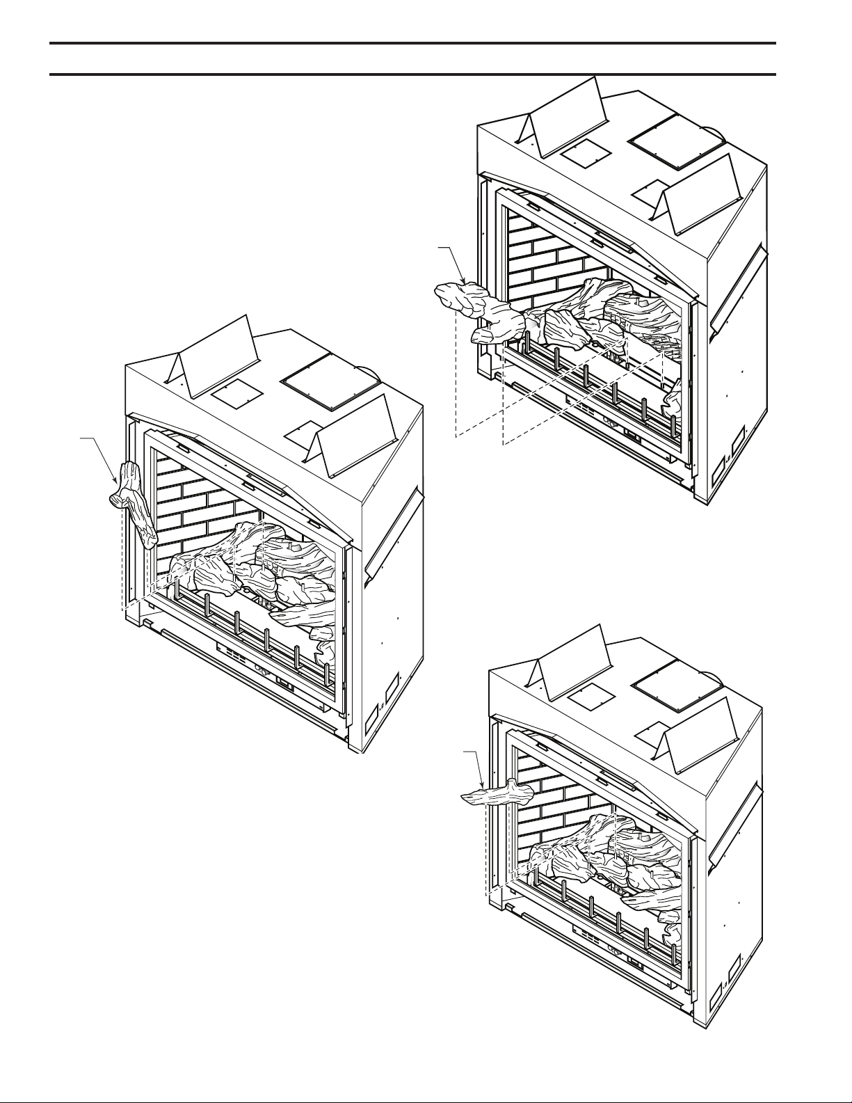
Right Mid Log
#7
LG809
Figure 42
7. Place right mid log (#7) on two
right pins on burner assembly.
Figure 42
Top Left
Log #4
LG806
Figure 43
8. Place top left log (#4) on two
pins on left mid log. Figure
43
Right Top
Log #5
LG807
Figure 44
9. Place right top log (#5) on two pins
on middle left log. Figure 44
51D0528
31
LX Series Direct Vent Gas Fireplace
Center Log #8
LG806
Figure 45
10. Place top center log (#8)
across rear log (#1) pin and
left mid log (#6) pin. Figure
45
Rockwool
LG810
Figure 46
Rockwool
Air Space Under Rear Log
11. Break up rock wool (ember material) into dime-
sized pieces. Place evenly across both burner
surfaces. Figure 46. Do not exceed 1/2" depth
of coverage.
32
51D0528
LX Series Direct Vent Gas Fireplace
Bend Tabs Up
for All Vertical
Applications
Only
Air Restrictor
Slide Left
and Right
FP2719
Screw
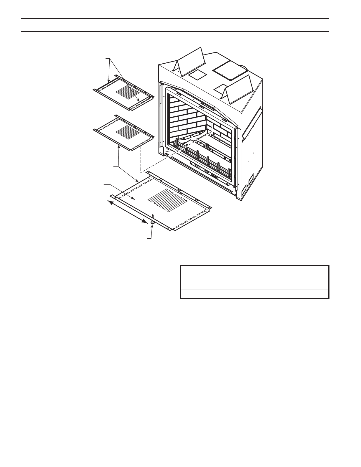
The replace is equipped with a restrictor plate that is
located inside the top chamber of the replace. Depending
upon the vent conguration, you may be required to adjust
the restrictor position
1. Remove glass frame. Refer to Glass Frame Removal,
Page 27.
2. Using a Phillips screw driver, loosen the screw that
secures the air restrictor. Do not back the screw all the
way out.
3. Slide the bafe on top of the restrictor plate such that it
blocks a percentage of the grill opening. Refer to the
chart for recommended settings.
8 to 20 100% (Factory Setting)
20 to 30 50%
30 to 40 0%
Figure 47 -
Adjust Bafe on Air Restrictor
Plate
51D0528
33
LX Series Direct Vent Gas Fireplace
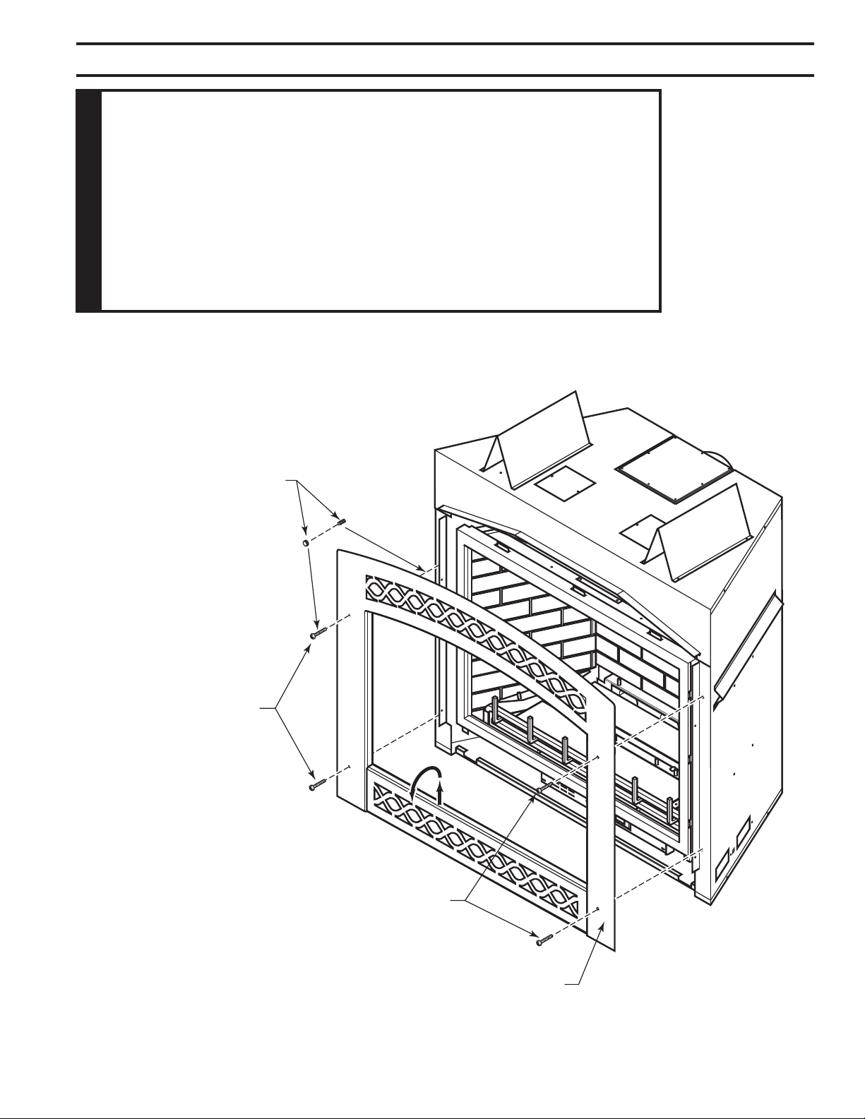
Figure 48
1. Align the four (4) holes on the facing with the four (4)
holes on the replace.
2. Attach facing with four (4) fasteners provided.
Decorative Finish
Facings use Finale
Nuts and Studs
Standard Black
Facings use Bolts
Bolts
Facing
FP2720
Figure 48 -
Install Filigree Facing
34
51D0528
LX Series Direct Vent Gas Fireplace
This appliance is equipped with a pilot which must be lit with built-in ignitor while following these
instructions exactly.
BEFORE OPERATING smell all around the appliance area for gas. Be sure to smell next to the oor
because some gas is heavier than air and will settle on the oor.
• Turn off all gas to the appliance.
• Open windows.
• Do not attempt to light any appliance.
• Do not touch any electric switch; do not use any phone in your building.
• Immediately call your gas supplier from a neighbor's phone. Follow the gas supplier's instruc-
tions.
• If you cannot reach your gas supplier, call the re department.
Use only your hand to push in, or turn the gas control knob. Never use tools. If the knob will not
push in or turn by hand, don't try to repair it. Call a qualied service technician. Force or attempted
repair may result in a re or explosion.
Do not use this appliance if any part of it has been under water. Immediately call a qualied service
technician to inspect the appliance and to replace any part of the control system and any gas control
that has been under water.
Purge air from the supply line as follows:
• Open main shutoff valve.
• Unscrew main pressure test point.
• Leave inlet test screw open until gas comes in.
• When gas is owing, tighten inlet screw immediately.
1. Follow the pipe from the gas supply line connection to the gas valve. Check connection for leaks with
soap and water mixture.
2. Next check for gas leaks at the burner with soap and water mixture.
3. Check the pilot for gas leaks with soap and water mixture.
51D0528
35
LX Series Direct Vent Gas Fireplace
You may check for gas leaks with the following
methods only:
• Soap and water solution
• An approved leak testing spray
• Electronic sniffer
1. Depress and turn knob counterclockwise
to
pilot position.
2. Depress fully and hold pilot gas knob. Depress piezo
ignitor as many times as needed to ignite the pilot.
Keep knob fully depressed for a few seconds.
Release and check that pilot continues to burn.
If the pilot does not stay lit, repeat steps 1 and 2.
Figure 49 -
Pilot Position
Check for gas leaks in each of the following locations:
• Pipe from the gas supply line connection to the gas valve
• Burner connections • Field made joints / gas shutoff valve
• Pilot • Factory made joints
• Each joint or connection • All joints on valve and control body
PILOT
O
F
F
P
I
L
O
T
O
N
36
51D0528
LX Series Direct Vent Gas Fireplace
O
F
F
P
I
L
O
T
O
N
PILOT
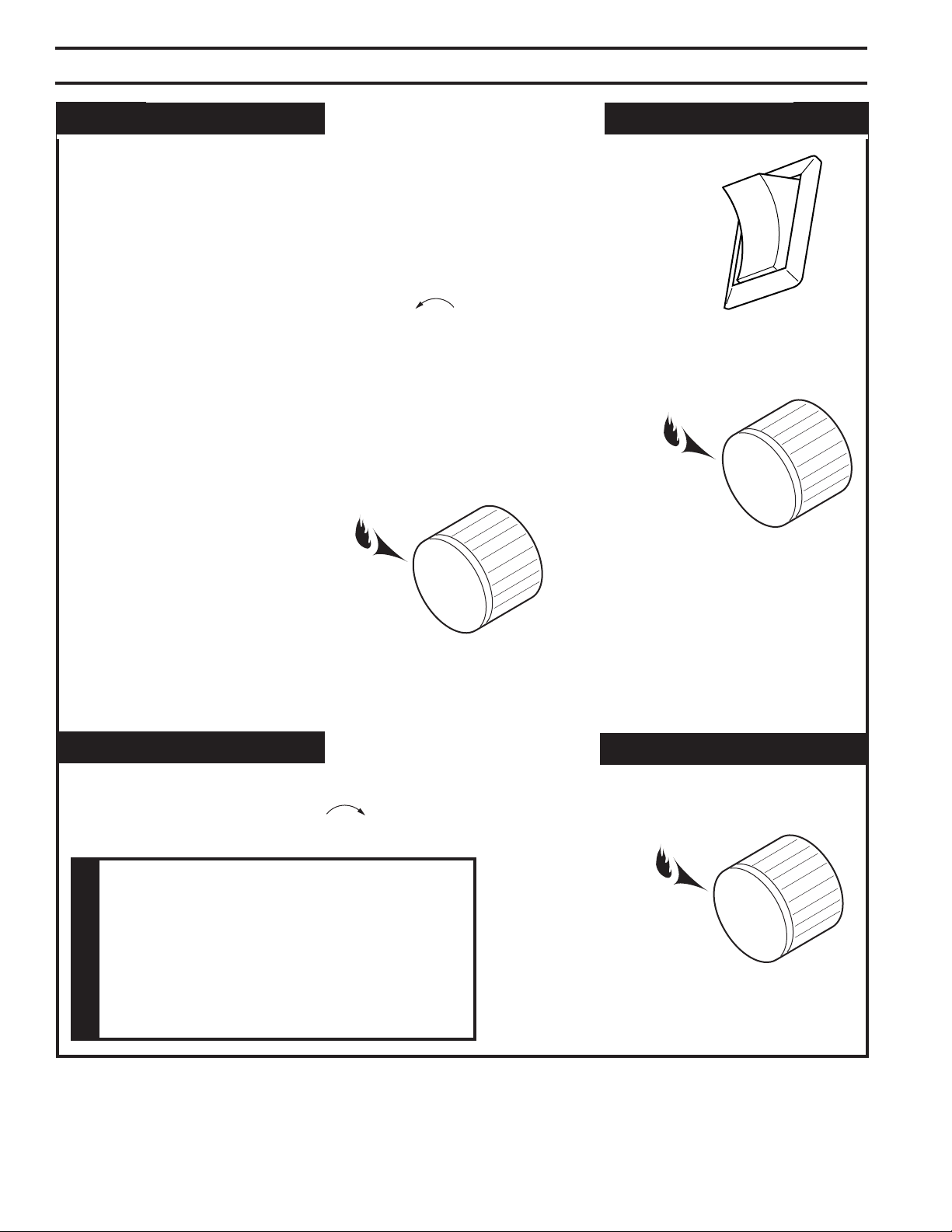
The “ON/OFF/RS” switch for the main burner can be found behind door of the
replace. This switch allows you to turn on and to turn off the main burner without
using the gas valve knob. Make sure the button is in the “ON” position to light
the main burner. Figure 50
Depress and turn the knob counterclockwise to the “ON” position. Figure
51. It will take less than four (4) seconds for the burner to ignite.
Depress and turn knob to pilot position to keep burner off while maintaining the
pilot light. Figure 52
Depress and turn knob clockwise to “OFF” position. Figure 53
Figure 52 -
Pilot Position
PILOT
O
F
F
P
I
L
O
T
O
N
PILOT
O
F
F
P
I
L
O
T
O
N
OFF
ON
RS
Figure 53 -
Off Position
Figure 51 -
On Position
Figure 50 -
On/Off/RS Switch
51D0528
37
LX Series Direct Vent Gas Fireplace
and
Make sure the gas valve knob is in the “OFF” position.
Wait at least ve (5) minutes before start-ing maintenance.
Fireplace must be cold before starting maintenance.
A qualied agency should examine the venting system
annually.
Clean the ceramic glass periodically. Condensation will
sometimes form on the glass during a cold startup. This
is normal for all gas replaces. This condensation often
attracts dust and lint to the surface of the glass. The initial
paint curing of the appliance can also leave a slight lm
on the glass.
Your should clean the glass after the rst two weeks of
use. After that, you should clean the glass no more than
two or three times a season. Use a mild glass cleaner to
clean the door.
Visually check pilot and burner ames periodically. Refer
to Figure 54 for typical burner ame. Refer to Figure 55
for typical pilot ame.
1. Carefully remove log set, and embers from combustion
chamber.
2. Vacuum burner compartment thoroughly.
3. Vacuum any dust off logs.
4. Remove any lint from main burner and pilot.
5. Carefully replace log set, and embers in their correct
positions. Page 28
6. Replace door (if it has been removed).
7. Relight pilot. Page 35
8. Turn on main burner.
Thermocouple
Thermopile
FP2721
Figure 54 -
Typical Pilot Flame
Figure 55 -
Typical Burner Flame
Appearance
LG812
38
51D0528
LX Series Direct Vent Gas Fireplace
• Never operate replace if glass is broken.
• Replace any glass that is chipped, cracked, or broken.
Replacement glass assemblies MUST be supplied by
replace manufacturer —
and
LX32
LX36
FP2722
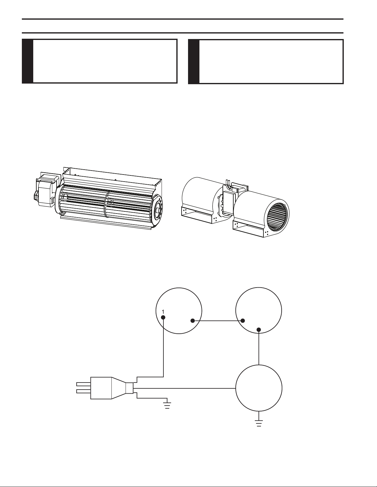
White
(Hi Temp)
OFF
Variable
Fan Control
ON
White
(Hi Temp)
Fan Limit
Switch
(N.O.)
White
(Hi Temp)
Blower
Motor
Black
White
Green
110/115 V.A.C
Blower Plug
51D0528
39
LX Series Direct Vent Gas Fireplace
Spark ignitor will not light the
pilot after repeated pressing of
spark ignitor.
Pilot will not stay lit.
Burner will not light when valve
and burner switch are both on.
Glass fogs up
Blue ames
Sooting
1. Battery needs replacing
2. Defective ignitor
3. Misaligned spark electrode
4. Bad wire.
1. Defective thermocouple.
Loose thermocouple
2. Air in gas line
3. No gas
1. Defective switch
2. Defective thermopile
3. Thermostat set too low/defective
1. Normal condition
1. Normal during start up
1. Flame impingement
1. Replace battery
2. Check connections to ignitor. Replace
ignitor if ignitor connections are good,
but there is no spark.
3. Check for spark arcing from the elec-
trode to pilot. Adjust and retighten.
4. Replace with new wire.
1. A. Check for proper connection of
thermocouple to rear of valve.
B. Check thermocouple output.
2. Bleed line. Contact dealer
3. Check shutoff valve and gas supply
(LPG tank)
1. Check switch connections. Jump
wires at switch.
2. A. Check thermopile output.
B. Check connections to valve. Con-
tact dealer.
3. Turn up thermostat to start unit.
Check thermostat connections.
1. Allow appliance to warm up. Glass
will clear. Additives in the gas may
dirty glass. Clean glass when cool.
1. Flames will yellow as appliance
heats up. Adjust rock wool placement
per instructions.
1. Check log position. Open shutters to
increase primary air.
40
51D0528
LX Series Direct Vent Gas Fireplace
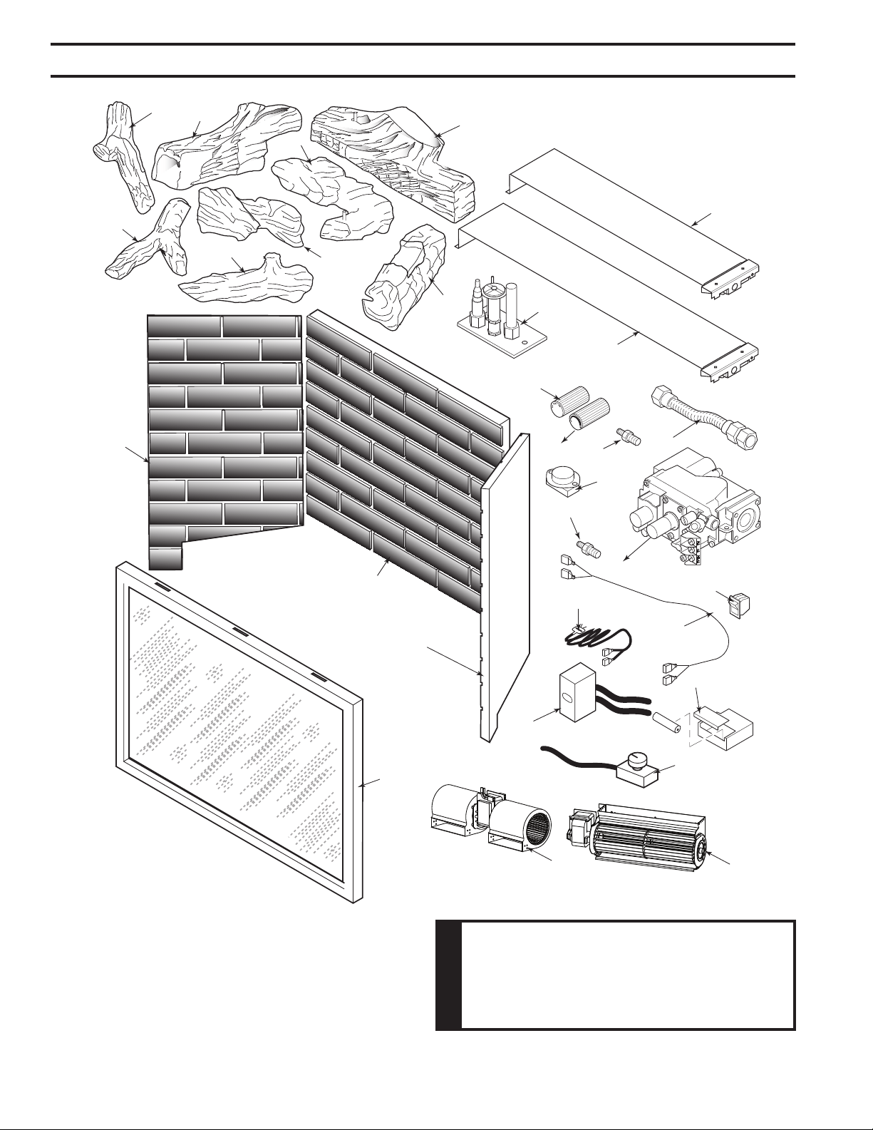
19
20
21
22
23
24
25
26
27
28
29
17
18
2
3
1
6
7
4
5
8
9
10
12
13
14
15
16
11
9
LX32
LX36

51D0528
41
LX Series Direct Vent Gas Fireplace
1. Rear Log 1 51D0402 51D0402 51D0002 51D0002
2. Bottom Left Log 1 51D0403 51D0403 51D0003 51D0003
3. Bottm Right Log 1 51D0404 51D0404 51D0004 51D0004
4. Left Top Log 1 51D0405 51D0405 51D0005 51D0005
5. Right Top Log 1 51D0406 51D0406 51D0006 51D0006
6. Left Mid Log 1 51D0407 51D0407 51D0007 51D0007
7. Right Mid Log 1 51D0408 51D0408 51D0008 51D0008
8. Center Log 1 51D0409 51D0409 51D0009 51D0009
9. Blower UPPCO 1 20302445 20302445 1601881 1601881
10. Speed Control 1 26D0746 26D0746 26D0746 26D0746
11. Thermostat Sensor 1 26D2870 26D2870 26D2870 26D2870
12. Junction Box 1 26D2128K 26D2128K 26D2128K 26D2128K
13. Glass Assembly 1 51D0417K 51D0417K 51D0417K 51D0417K
14. Firebrick Center 1 51D0411 51D0411 51D0012 51D0012
15. Firebrick Left 1 51D0013 51D0013 51D0013 51D0013
16. Firebrick Right 1 51D0192 51D0192 51D0192 51D0192
17. Wire Harness Male 1 44D0501 44D0501 44D0501 44D0501
18. Wire Harness Female 1 44D0500 44D0500 44D0500 44D0500
19. SIT 820 Nova Valve 1 37D0117 37D0118 37D0117 37D0118
20. Knob Extension Hi/Lo 1 43D0095 43D0095 43D0095 43D0095
21. Knob Extension On/Off 1 43D0094 43D0094 43D0094 43D0094
22. Pilot Assembly 1 37D0018 37D0019 37D0018 37D0019
23. Front Burner Assembly 1 51D0037K 51D0037K 51D0037K 51D0037K
24. Rear Burner Assembly 1 51D0431K 51D0431K 51D0041K 51D0041K
25. Injector Front Burner 1 51D0425K 51D0423K 51D0032K 51D0030K
26. Injector Rear Burner 1 51D0425K 51D0422K 51D0031K 51D0029K
27. Flexhose w/Shutoff Valve 1 23D6046 23D6046 23D6046 23D6046
28. Rocker Switch 1 41D0048 41D0048 41D0048 41D0048
29. Ignitor Battery Assembly 1 45D0242K 45D0242K 45D0242K 45D0242K
(not shown)
Thermostatic Remote Control RCT, RCST, RCSTE, TSST, WWTD
Remote Control On/Off RCB, RCMT, RCBE, TSMT, WMTD
Wall Switch Kit MVWS
Wall Thermostat Kit WT
Deector Shield 37D0115K
LX32DVNV Kit #LX32CKP LX32HAKP*
LX36DVNV Kit #LX36CKP LX32HAKP*
LX32DVPV Kit #LX32CKN LX32HAKN*
LX36DVPV Kit #LX36CKN LX32HAKN*
*High Altitude Conversion Kits
42
51D0528
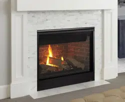
LX Series Direct Vent Gas Fireplace
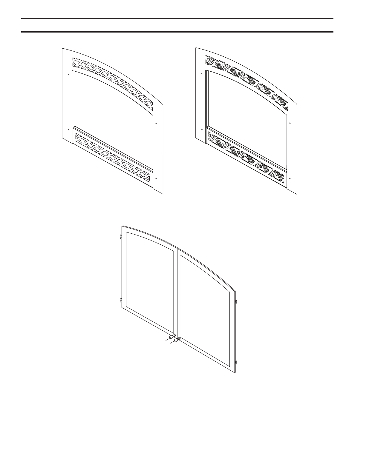
Available in:
Black, Textured Black, Vintage Iron,
Gold Tone, Brushed Pewter and Gold
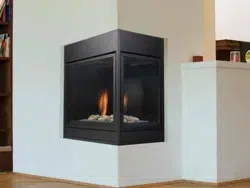
Available in:
Black, Textured Black, Vintage Iron,
Gold Tone, Brushed Pewter and Gold
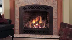
Available in:
Black, Textured Black, Vintage Iron,
Gold Tone, Brushed Pewter and Gold
51D0528
43
LX Series Direct Vent Gas Fireplace
Black Rolling "O" Decorative Arched Facing LX32RBL LX36RBL no
Black Nantucket Decorative Arched Facing LX32NBL LX36NBL no
Rectangular Front Nantucket Black LX32RNBL LX36RNBL no
Textured Black Rolling "O" Decorative Arched Facing LX32RTB LX36RTB yes
Textured Black Decorative Arched Facing LX32NTB LX36NTB yes
Rectangular Front Nantucket Black LX32RNTB LX36RNTB yes
Vintage Iron Rolling "O" Decorative Arched Facing LX32RVI LX36RVI yes
Vintage Iron Nantucket Decorative Arched Facing LX32NVI LX36NVI yes
Rectangular Front Nantucket Vintage Iron LX32RNVI LX36RNVI yes
Gold Tone Rolling "O" Decorative Arched Facing LX32RGT LX36RGT yes
Gold Tone Nantucket Decorative Arched Facing LX32NGT LX36NGT yes
Brushed Pewter Rolling "O" Decorative Arched Facing LX32RBP LX36RBP yes
Brushed Pewter Nantucket Decorative Arched Facing LX32NBP LX36NBP yes
Textured Black Fire Screen Doors LX32FDDTB LX36FDDTB
Gold Tone Fire Screen Doors LX32FDDGT LX36FDDGT
Vintage Iron Fire Screen Doors LX32FDDVI LX36VDDVI
Brushed Pewter Fire Screen Doors LX32FDDBP LX36FDDBP
44
51D0528
LX Series Direct Vent Gas Fireplace
HOT
1
2
3
4
5
6
9
7
8
11
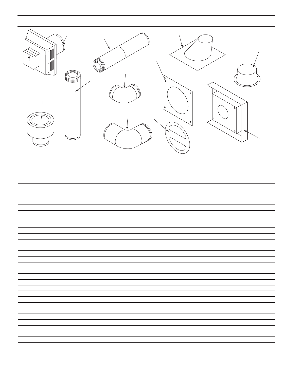
10
1 1 Thru-roof Flexible Pipe Termination Kit with ex adapter TRFK -- -- --
24" rigid pipe, roof support 4" x 6
5
/8" and termination cap
1 1 Horizontal Square Termination Cap with built-in vinyl BHRTK BHRTK -- --
siding standoff, heat deector and restop
1 1 Square Horizontal Termination Cap 46DVA-HC 985 4DT-HC 4DHT
1 1 Round Horizontal Termination Cap 46DVS-HRCS -- -- --
1 1 Sconce Termination Cap (aluminum) 46DVA-HSC -- -- --
2 1 Low-Prole Vertical Termination Cap 46DVA-VC 980 4DT-VC 4DVT
3 6 6" Pipe Length (galvanized) 46DVA-06 908 4DT-06 4DV6
3 6 9" Pipe Length (galvanized) 46DVA-09 907 4DT-09 --
3 6 12" Pipe Length (galvanized) 46DVA-12 906 4DT-1 4D12
3 6 24" Pipe Length (galvanized) 46DVA-24 904 4DT-4 4D24
3 6 36" Pipe Length (galvanized) 46DVA-36 903 4DT-36 4D36
3 6 48" Pipe Length (galvanized) 46DVA-48 902 4DT-48 4D48
4 6 8Z\x" Pipe Extension (galvanized) 46DVA-08A -- 4DT-AJ --
4 6 16" Pipe Extension (galvanized) 46DVA-16A -- 4DT-AJ14 --
5 6 45° Elbow (galvanized) 46DVA-E45 945 4DT-EL45 4D45L
6 6 90° Elbow (galvanized) 46DVA-E90 990 4DT-EL90 4D90L
7 6 Adjustable Roof Flashing 0/12 - 6/12 46DVA-F6 943 4DT-AF6 4DF
8 6 Storm Collar 46DVA-SC 953 4DT-SC 4F5C
9 6 1" Firestop 46DVA-FS 963 4DT-FS 4DF5
9 6 3" Firestop FS3 -- -- --
10 1 Vinyl Siding Standoff 46DVA-VSS 950 4DT-VS 4DVS
11 1 Restrictor Disk 45D0551 45D0551 -- --
1 Attic Insulation Shield 46DVA-IS -- -- --
6 Steep Roof Flashing 7/12 - 12/12 46DVA-F12 943S -- --
8 Horizontal Termination with 1" restop BHRT/8 -- -- --
8 Flex Adapter Starter DVFA/8 -- -- --
B\,
Z\x
For more information about, or instructions for, the venting components referenced, please contact the component manufacturer:
Selkirk Corporation: www. selkirkcorp.com or 800-992-8368; Simpson Duravent: www. duravent.com or 800-835-4429;
Metal-Fab, Inc.: www.metal-fabinc.com or 316-943-2351

51D0528
45
LX Series Direct Vent Gas Fireplace

46
51D0528
LX Series Direct Vent Gas Fireplace
This product must be installed by a licensed plumber or gas tter
when installed within the Commonwealth of Massachusetts.
Any residence with a direct vent product must have a CO
detector installed in the residence.
Installation of the replace or vented gas log in the State of
Massachusetts requires the damper to be permanently removed
or welded in the fully open position.
In addition, a naturally vented gas log may not be installed in a
bedroom or bathroom in the State of Massachusetts.
Flex line installation must not exceed 36 inches and must have
a T shutoff valve.
This product must be installed by a licensed plumber or gas tter
when installed within the Commonwealth of Massachusetts.
In addition, vent free products may not be installed in a
bedroom or bathroom regardless of size or type in the State of
Massachusetts.
Flex line installation must not exceed 36 inches and must have
a T shutoff valve.
(2) Revise 10.8.3 by adding the following additional
requirements:
(a) For all side wall horizontally vented gas fueled
equipment installed in every dwelling, building or structure used
in whole or in part for residential purposes, including those
owned or operated by the Commonwealth and where the side
wall exhaust vent termination is less than seven (7) feet above
nished grade in the area of the venting, including but not
limited to decks and porches, the following requirements shall
be satised:
1. At the time
of installation of the side wall horizontal vented gas fueled
equipment, the installing plumber or gas tter shall observe
that a hard wired carbon monoxide detector with an alarm and
battery back-up is installed on the oor level where the gas
equipment is to be installed. In addition, the installing plumber
or gas tter shall observe that a battery operated or hard wired
carbon monoxide detector with an alarm is installed on each
additional level of the dwelling, building or structure served by
the side wall horizontal vented gas fueled equipment. It shall be
the responsibility of the property owner to secure the services of
qualied licensed professionals for the installation of hard wired
carbon monoxide detectors
a. In the event that the side wall horizontally vented gas
fueled equipment is installed in a crawl space or an attic, the
hard wired carbon monoxide detector with alarm and battery
back-up may be installed on the next adjacent oor level.
b. In the event that the requirements of this subdivision
can not be met at the time of completion of installation, the
owner shall have a period of thirty (30) days to comply with the
above requirements; provided, however, that during said thirty
(30) day period, a battery operated carbon monoxide detector
with an alarm shall be installed.
2. Each carbon
monoxide detector as required in accordance with the above
provisions shall comply with NFPA 720 and be ANSI/UL 2034
listed and IAS certied.
3. A metal or plastic identication plate shall be
permanently mounted to the exterior of the building at a
minimum height of eight (8) feet above grade directly in line
with the exhaust vent terminal for the horizontally vented
gas fueled heating appliance or equipment. The sign shall
read, in print size no less than one-half (1/2) inch in size,
“GAS VENT DIRECTLY BELOW. KEEP CLEAR OF ALL
OBSTRUCTIONS.”
4. The state or local gas inspector of the side
wall horizontally vented gas fueled equipment shall not
approve the installation unless, upon inspection, the inspector
observes carbon monoxide detectors and signage installed
in accordance with the provisions of 248 CMR 5.08(2)(a)1
through 4.
(b) The following equipment is exempt from
248 CMR 5.08(2)(a)1 through 4:
1. The equipment listed in Chapter 10 entitled "Equipment
Not Required To Be Vented" in the most current edition of
NFPA 54 as adopted by the Board; and
2. Product Approved side wall horizontally vented gas fueled
equipment installed in a room or structure separate from the
dwelling, building or structure used in whole or in part for
residential purposes.
(c)
When the manufacturer of Product
Approved side wall horizontally vented gas equipment provides
a venting system design or venting system components with
the equipment, the instructions provided by the manufacturer
for installation of the equipment and the venting system shall
include:
1. Detailed instructions for the installation of the venting
system design or the venting system components; and
2. A complete parts list for the venting system design or
venting system.
(d)
When the manufacturer of
a Product Approved side wall horizontally vented gas fueled
equipment does not provide the parts for venting the ue
gases, but identies “special venting systems,” the following
requirements shall be satised by the manufacturer:
1. The referenced "special venting system" instructions shall
be included with the appliance or equipment installation
instructions; and
2. The “special venting systems” shall be Product Approved
by the Board, and the instructions for that system shall include
a parts list and detailed installation instructions.
(e) A copy of all installation instructions for all Product
Approved side wall horizontally vented gas fueled equipment,
all venting instructions, all parts lists for venting instructions,
and/or all venting design

51D0528
47
LX Series Direct Vent Gas Fireplace
The following components are warranted for life to the original owner, subject to proof of pur-
chase: Firebox, Combustion Chamber, Heat Exchanger, Grate and Stainless Steel Burners.
The following components are warranted ve (5) years to the original owner, subject of proof
of purchase: Ceramic Fiber Logs.
MHSC warrants the components and materials in your gas appliance to be free from manufac-
turing and material defects for a period of two years from date of installation. After installation,
if any of the components manufactured by MHSC in the appliance are found to be defective in
materials or workmanship, MHSC will, at its option, replace or repair the defective components
at no charge to the original owner. MHSC will also pay for reasonable labor costs incurred in
replacing or repairing such components for a period of two years from date of installation. Any
products presented for warranty repair must be accompanied by a dated proof of purchase.
This Limited Lifetime Warranty will be void if the appliance in not installed by a qualied in-
staller in accordance with the installation instructions. The Limited Lifetime Warranty will also
be void if the appliance is not operated and maintained according to the operating instructions
supplied with the appliance, and does not extend to (1) rebox/burner assembly damage by
accident, neglect, misuse, abuse, alterations, negligence of others, including the installation
thereof by unqualied installers, (2) the costs of removal, reinstallation or transportation of
defective parts on the appliance, or (3) incidental or consequential damage. All service work
must be performed by an authorized service representative.
This warranty is expressly in lieu of other warranties, express or implied, including the war-
ranty of merchantability of tness for purpose and of all other obligations or liabilities. MHSC
does not assume for it any other obligations or liabilities in connection with sale or use of the
appliance. It states that do not allow limitations on how long an implied warranty lasts, or do
not allow exclusion of indirect damage, those limitations of exclusions may not apply to you.
You may also have additional rights not covered in the Limited Lifetime Warranty.
MHSC reserves the right to investigate any and all the claims against the Limited Lifetime
Warranty and decide upon method of settlement.
1. Contact your supplier. Make sure you have your warranty, your sales receipt and
the model/serial number of your MHSC product.
2. DO NOT ATTEMPT TO DO ANY SERVICE WORK YOURSELF.
149 Cleveland Drive • Paris, Kentucky 40361
www.mhsc.com
Based on CSA P.4.1-09
LX32DVN 65.1
LX32DVP 66.2
LX36DVN 66.8
LX36DVP 69.1