Loading ...
Loading ...
Loading ...
HOWTOSET-UPYOURMOWER(cam'D)
TO ADJUST HEIGHT OF CUT
NOTE: The wheels are setin a low positionfor ship-
ment, and should be adjusted for the cutting
height desired before use.
CAUTION: DO NOT change the height of cut with
the engine running.
1. The wheel adjusters give you five (5) different
cutting positions. Medium cut is the best for
most lawns.
2. High cut isapproximately 3 5/8", medium cut
isapproximately 2 1/2", and lowcutisapproxh
imately 1 3/8". There are two other positions.
Pick the position which suits your lawn (See
Fig. 7).
3, Thewheel adjusters onyour lawn mowercan be
easily adjusted as shown in Fig. 8. To change
the height of cut, squeeze adjuster lever to-
ward the wheel, moving up or down toselected
height. Be sure all wheels are in the same
setting (See Fig. 7).
4. When cutting in heavy or moistgrass, the rear
of the lawn mower may be raised one setting
higher to allow better discharge of the grass.
TO ASSEMBLE GRASS CATCHER
NOTE: The grass catcher for your mower is sup-
plied unassembled. To assemble your grass cat-
cher follow steps below.
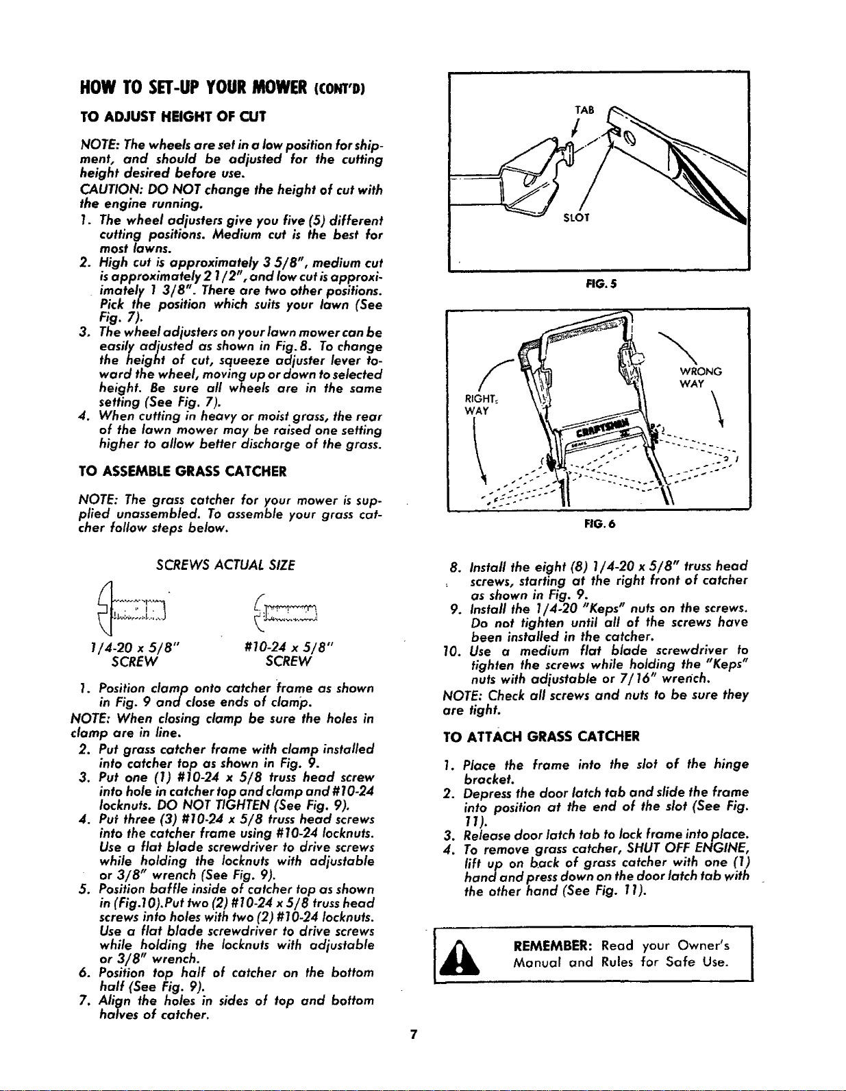
TAB
FIG. $
I
S _ " WRONi
WAY
RIGHT:
WAY
FIG. 6
SCREWS ACTUAL SIZE
1/4-20 x 5/8" #10-24 x 5/8"
SCREW SCREW
1. Position clamp onto catcher frame as shown
in Fig. 9 and close ends of clamp.
NOTE: When closing clamp be sure the holes in
clamp are in line.
2. Put grass catcher frame with clamp installed
into catcher top as shown in Fig. 9.
3. Put one (1) #10-24 x 5/8 truss head screw
into hole in catcher top and clamp and #10-24
Iocknuts. DO NOT TIGHTEN (See Fig. 9).
4. Put three (3) #10-24 x 5/8 trusshead screws
into the catcher frame using #10-24 Iocknuts.
Use a flat blade screwdriver to drive screws
while holding the Iocknuts with adjustable
or 3/8" wrench (See Fig. 9).
5. Positionbaffle inside of catcher top as shown
in (Fig.lO).Put two (2) #10-24 x 5/8 truss head
screwsinto holes with two (2) #10-24 Iocknuts.
Use a flat blade screwdriver to drive screws
while holding the Iocknuts with adjustable
or 3/8" wrench.
6. Position top half of catcher on the bottom
half (See Fig. 9).
7. Align the holes in sides of top and bottom
halves of catcher.
8. Install the eight (8) 1/4-20 x 5/8" truss head
screws, starting at the right front of catcher
as shown in Fig. 9.
9. Install the 1/4.20 "Keps" nuts on the screws.
Do not tighten until all of the screws have
been installed in the catcher.
10. Use a medium flat blade screwdriver to
tighten the screws while holding the "Keps"
nuts with adjustable or 7/16" wrench.
NOTE: Check all screws and nuts to be sure they
are tight.
TO ATTACH GRASS CATCHER
1. Place the frame into the slot of the hinge
bracket.
2. Depress the door latch tab and slide the frame
into position at the end of the slot (See Fig.
11).
3. Release door latch tab to lock frame intoplace.
4. To remove grass catcher, SHUT OFF ENGINE,
lift up on back of grass catcher with one (1)
hand and pressdown on the door latch tab with
the other hand (See Fig. 11).
REMEMBER: Read your Owner's
Manual and Rules for Safe Use.
!
Loading ...
Loading ...
Loading ...