
Loading ...
Loading ...
Loading ...
EN - 6
6.1.1
6.1.2
NOTE -
a.
the grass catcher:
1.
-
2. Insert the grass catcher (Fig.12.C).
b.
discharge on the ground:
1.
(Fig.13.B).
2.
-
c.
Lift the rear discharge guard (Fig.14.A) and insert the
pins (Fig.14.B.1) in the provided holes, until the engage-
(Fig. 14.D).
d. -
charge on the ground:
1. Lift the rear discharge guard (Fig.15.A) and insert the
-
-
2.
discharge guard (Fig.15.D).
3. Insert the side discharge chute (Fig.15.E).
4.
the side discharge chute (Fig.15.E).
5.
side discharge guard (Fig.15.D).
6. Release the side discharge chute (Fig.15.E).
6.2 SAFETY CHECKS
6.2.1
• -
• -
• .
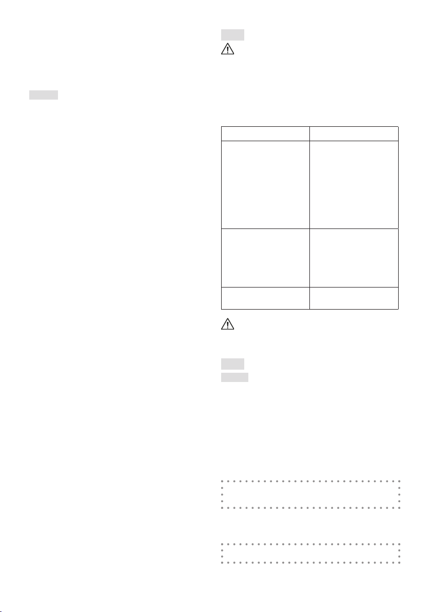
6.2.2 Machine operating test
Action Result
1. Start the machine and
engage the cutting
2. Release the operator
presence lever (Fig.21
A).
1.
2. The lever should return
position, the engine
seconds.
1. Start the machine (par.
6.3) and operate the
drive lever (par. 5.2.3).
2. Disengage the drive
lever.
1. The wheels should
move the machine
forward.
2.
Test driving
If any of the results fail to match the indications
provided in the tables, do not use the machine! Contact
an Authorised Service Centre to have it checked and
repaired if necessary.
6.3
NOTE -
cles or high grass.
1. -
2.
the electrical contact.
3. -
4.
5.
6.
-
ator presence lever (Fig.19.B).
7. To engage the traction, press the lever behind the
handle (Fig.19.C).
Loading ...
Loading ...
Loading ...