PoulonPRO
Please do not return unit to retailer.
_1_ Por favor, no devuelva el aparato al lugar de compra.
Veuillez ne pas retourner I'outil au d_taillant.
• 1-800-554-6723
www.poulan-pro.com
Instruction Manual
Manual de Instrucciones
Manuel d'lnstructions
PP4520AV
_L ARNING:Read and follow atl Safety Rules and Operating instructions before
using this product. Failureto do so can result in serious injury.
ADVERTENCIA:
Lea el manual de instrucciones ysiga todas Iasadvertencias e en-
strucciones de seguridad, El no hacerto puede resultar en tesiones
graves.
AVERTISSEMENT:
Life le manuel d'instructions et bien respecter tous tes avertisse-
ments et toutes les instructions de s_curite. Tout defaut de le faire
pourrait entrainer des bIessures graves.
Poulan PRO
t030 Stevens Creek Road
Augusta, GA 30907
PoutanPRO
5855Terry Fox Way
Mississauga, Ontario L5V 3E4
545186772 Rev. 1 4/15/08 BRW
--_ ARNING! This chain _"_
saw can bedangerous! Care-
lessor improperuse car Cause
seriousor even fatal injury
Read and understand the
instruction manuaI before
using the chain saw.
A_ways wear appropriate ear protection, eye protection and head protection.
_,_ (_ A_ways use two hands when operating the chain saw.
@
WARNING! Contacting the guide bartipwith any object
should be avoided; tip contact may cause the guide bar to
move suddenly upward and backward, which may cause se-
dous injury.
Measured maximum kickback value without chain brake for the bar
and chain combination on the Iabel.
Starting Reminder
Move ON/STOP switch to
*'._1J the ON position.
Turl_"ON"
Puli choke/fast idle Iever
.1_. ut to the fuII extent (to
the FULL CHOKE posi-
Full Choke tion).
Putl the starter rope
I_llr_ sharpIy 5 times with your
-- - right hand
PuI! 5X
i
!/z. £9J
q_'_
Half Choke
Pull ToSlert
i
Push the choke/fast id}e
lever in to the HALF
CHOKE position.
Pull the starter rope sharply
with your right hand unt_I
the engine starts.
,_k WARNING: Always disconnect
spark pIug wire and place wire where itcan-
not contact spark plug to prevent accidental
starting when setting up, transporting, ad-
justing or making repairs except carburetor
adiustments.
Secause a chain saw is a high-speed wood-
cutting tool, special safety precautions must
be observed to reduce the risk of accidents.
Careless or i_proper use of this tool can
Cause serious Enjury
PLAN AHEAD
• Read this manual carefully unti} you com-
pletafy understand and can fallow all safety
rules, precautions, and operating instruc-
_ons before attempting to use the unit.
• Restrict the use of your saw to adutt users
who understand and can fotlow safety
rules, precautions, and operating instruc-
tions found in this manual.
• Wear protec_*ve gear Always use steel-toed
safety footwear with non-slip soles; snug-lit-
tJng clothing; heaw-duty, non-slip gloves;
eye protection such as non-fogging, vented
goggles or face screen; an approved safety
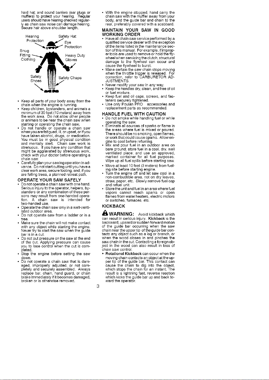
hard hat; and sound barriers (ear plugs or
mufflers) to protect your hearing. Regular
users shouidhavehearing checkedregular-
ly as chainsaw noisecan damage hearing.
Secure hairabove shoulder length.
Hearing Safety Hat
Protection _ Eye
"''_ i _J "I Protection
Snug
Fitting Heavy Duty
Clothing Gloves
Safety Safety Chaps
Shoes
• Keep all parts of your body away from the
chain when the engine is running.
• Keep children, bystanders, and animals a
minimum of 30 feet (10 meters) away from
the work area. Do not allow other people
or animals to be near the chain saw when
starting or operating the chain saw.
• Do not handle or operate a chain saw
when you are fatigued, ill, or upset, or if you
have taken alcohol, drugs, or medication.
You must be in good physical condition
and mentally alert. Chain saw work is
strenuous. If you have any condition that
might be aggravated by strenuous work,
check with your doctor before operating a
chain saw
•Carefuily plan your sawing operation inad-
vance. Do not start cutting until you have a
clear work area, secu re footing, and, if you
are feliing trees, a p}anned retreat path.
OPERATE YOUR SAW SAFELY
• Do not operate a chain saw with one hand.
Serious injury to the operator, helpers, by-
standers or any combination of these per-
sons may result from one-handed opera-
tion. A chain saw is intended for
two-handed use
• Operate the chain saw only in a weIFventi-
lated outdoor area.
• Do not operate saw from a ladder or in a
tree.
• Make sure the chain wil_ not make contact
with any object while starting the engine.
Never try to start the saw when the guide
bar is in a cut.
• Do not put pressure on the saw at the end
of the cut. Applying pressure can cause
you to iose control when the cut is com-
pleted.
• Stop the engine before setting the saw
down.
• Do not operate a chain saw that is dam-
aged, improperly adjusted, or not com-
pletely and securely assembled. Always
replace bar, chain, hand guard, or chain
brake immediately if it becomes damaged,
broken or is otherwise removed.
• With the engine stopped, hand carry the
chain saw with the muffter away from your
body, and the guide bar and chain to the
rear. preferably covered with a scabbard.
MAINTAIN YOUR SAW tN GOOD
WORKING ORDER
• Have all chain saw service performed by a
qualified service dealer with the exception
of the items tisted in the maintenance sec-
tion ofthis manual. For example, ifimprop-
er tools are used to remove or hold the fly-
wheelwhen servicing the clutch, structural
damage to the flywheel can occur and
cause the flywheel to burst.
• Make certain the saw chain stops mowng
when the throttle trigger is reteased. For
correction, refer to CARBURETOR AD-
JUSTMENTS
• Never modify your saw in any way
• Keep the handles dry, clean, and free of oil
or fuel mixture.
• Keep fuel and oil caps, screws, and fas-
teners securely tightened.
• Use only Poulan PRO accessories and
rep}acement parts as recommended
HANDLE FUEL WITH CAUTION
• Do not smoke while handIing fuel or while
operating the saw.
• Eliminate all sources of sparks or flame in
the areas where fuel is mixed or poured.
There should be no smoking, open flames,
or work that could cause sparks. Aliow en-
gine to cool before refueling.
• Mix and pour fuel in an outdoor area on
bare ground; store fuel in a cool, dry, well
ventilated piace; and use an approved,
marked container for all fuel purposes
Wipe up all fuel spills before starting saw
• Move at least f Ofeet (3 meters) from fuel-
ing site before starting engine.
• Turn the engine off and let saw cool in a
non-combustible area. not on dry ieaves,
straw, paper, etc. Slowly remove fuel cap
and refuel unit.
• Store the unit and fuelin an area where fuel
vapors cannot reach sparks or open
flames from water heaters, electric motors
or switches, furnaces, etc.
KICKBACK
WARNING: Avoid kickback which
can result in serious injury. Kickback is the
backward, upward or sudden forward motion
of the guide bar occurring when the saw
chain near the upper tip of the guide bar con-
tacts any object such as a log or branch, or
when the wood closes in and pinches the
saw chain in the cut. Contacting a foreign ob-
ject in the wood can also result in loss of
chain saw control.
• Rotational Kickback can occur when the
moving chain contacts an object at the up-
per tip of the guide bar. This contact can
cause the chain to dig into the object,
which stops the chain for an instant. The
result is a iightnJng fast, reverse reaction
which kicks the guide bar up and back to-
ward the operator.
• Pinch-Kickbackcanoccurwhenthethe
woodclosesinandpinchesthemoving
sawchaininthecutalongthetopofthe
guidebarandthesawchainissuddenly
stopped.Thissuddenstoppingofthe
chainresultsinareversalofthechain
forceusedtocutwoodandcausesthe
sawtomoveintheoppositedirectionofthe
chainrotation.Thesawisdrivenstraight
backtowardtheoperator.
• Pull4n can occur when the moving chain
contacts a foreign object in the wood in the
cut along the bottom of the guide bar and the
saw chain is suddenly stopped. This sudden
stopping pulls the saw forward and away
from the operator and could easily cause the
operator to lose control d the saw
Avoid Pinch-Kickback:
• Be extremely aware of situations or ob-
structions that can cause material to pinch
the top of or otherwise stop the chain.
• Do not cut more than one log at a time
• Do not twist the saw as the bar is with-
drawn from an undercut when bucking.
Avoid Pull-In:
• Always begin cutting with the engine at full
speed and the saw housing against wood.
• Use wedges made of plastic or wood.
Never use metal to hoid the cut open
Make sure the chain brake nuts are se-
curely tightened after tensioning the chain
• SeginandcontinuecuttingatfulIspeed. If
the chain is moving at a slower speed,
there is greater chance of kickback occur-
ring
• Cut one log ata time
• Use extreme caution when re-entering a
previous cut
• Do not attempt cuts starting with the tip of
the bar (pIunge cuts).
• Watch for shifting logs or other forces that
could close a cut and pinch or fall intochain
• Use the Reduced-Kickback Guide Bar
and Low-Kickback Chain specified for
your saw.
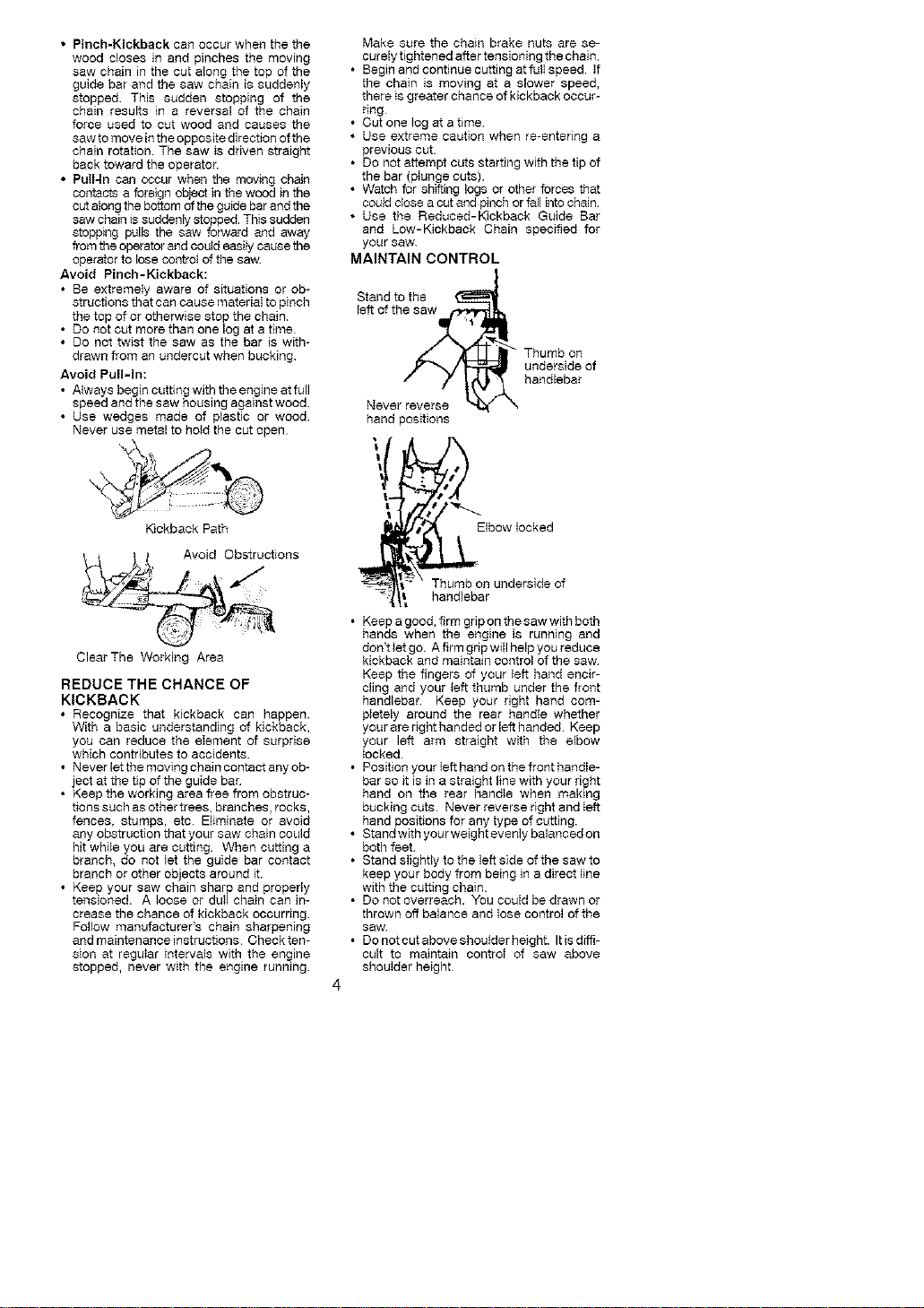
MAINTAIN CONTROL
Stand to the
left of the saw ,t
_ Thumb on
underside of
handlebar
Never
hand positions
Kickback Path
_#_ ._2#_' Avoid Obstructions
ClearThe Working Area
REDUCE THE CHANCE OF
KICKBACK
• Recognize that kickback can happen.
With a basic understanding of kickback,
you can reduce the element of surprise
which contributes to accidents.
• Never let the moving chain contact any ob-
ject at the tip of the guide bar
• Keep the working area free from obstruc-
tions such as other trees, branches, rocks,
fences, stumps, etc Eliminate or avoid
any obstruction that your saw chain could
hit while you are cutting When cutting a
branch, do not let the guide bar contact
branch or other objects around it.
• Keep your saw chain sharp and properly
tensioned. A loose or dull chain can in-
crease the chance of kickback occurring.
Follow manufacturer's chain sharpening
and maintenance instructions Check ten-
sion at regular intervals with the engine
stopped, never with the engine running.
Thumb on underside of
handlebar
• Keep a good, firm gbp on the saw wkh both
hands when the engine is running and
don't }et go. A firm grip will help you reduce
kickback and maintain control of the saw
Keep the fingers of your left hand encir-
cling and your left thumb under the front
handlebar. Keep your right hand com-
pletely around the rear handle whether
your are right handed or left handed Keep
your left arm straight with the elbow
Iocked.
• Position your Ieft hand on the front handle-
bar so it is in a straight line with your right
hand on the rear handle when making
bucking cuts. Never reverse right and Ieft
hand positions for any type of cutting.
• Stand with your weight evenly balanced on
both feet.
• Stand slightly to the left side of the saw to
keep your body from being in a direct line
with the cutting chain
• Do not overreach. You could be drawn or
thrown off balance and lose control of the
saw
• Donotcutaboveshouiderheight. Itisdiffi-
cult to maintain controi of saw above
shouIder height
KICKBACK SAFETY FEATURES
_ll, WARNING: Thefol_owingfeatures
are included on your saw to help reduce the
hazard of kickback; however, such features
will not totally eliminate this danger. As a
chain sew user, do not rely only on safety de-
vices. You must follow all safety precau-
tions, instructions, and maintenance in this
manual to help avoid kickback and other
forces which can resuit in serious injury.
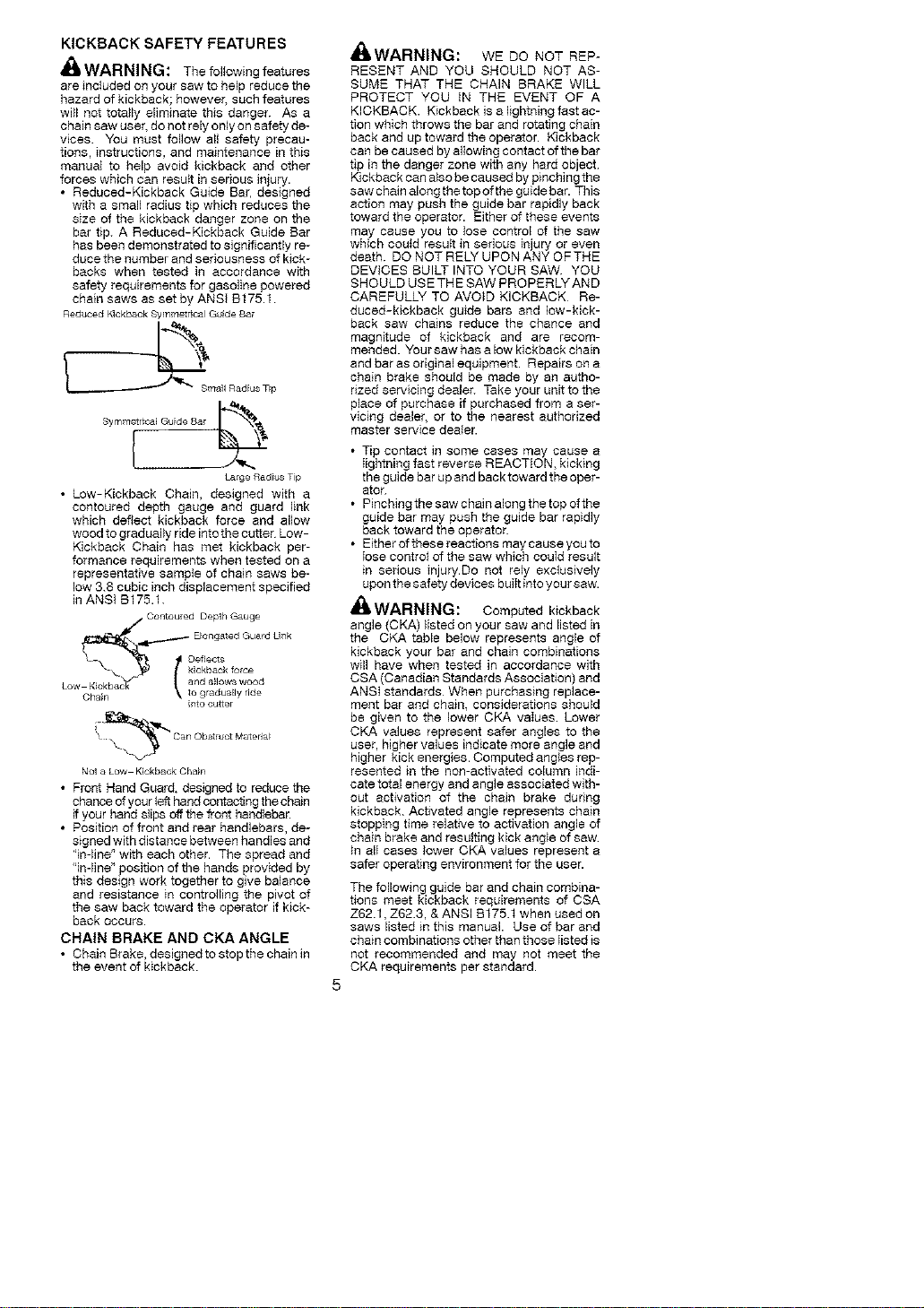
• Reduced-Kickback Guide Bar, designed
with a small radius tip which reduces the
size of the kickback danger zone on the
bar tip. A Reduced-Kickback Guide Bar
has been demonstrated to significantly re-
duce the number and seriousness of kick-
backs when tested in accordance with
safety requirements for gasoline powered
chain saws as set by ANSt B175.1
£educed Kickback Sylnm#t[ical Guide £ar
Symm_
LargeRadiusTip
• Low-Kickback Chain, designed with a
contoured depth gauge and guard link
which deflect kickback force and allow
wood to gradually ride into the cutter Low-
Kickback Chain has met kickback per-
formance requirements when tested on a
representative sample of chain saws be-
low 3.8 cubic inch displacement specified
in ANSi B175.1.
Chain
intocutter
Y _X ©anObs_l_ctM_teda_
Not_ Low Kic_bac_Chain
• Front Hand Guard, designed to reduce the
chance of your left hand contacting the chain
if your hand siips off the front handlebar.
• Position of front and rear handlebars, de-
signed with distance between handles and
"in-line" with each other. The spread and
'in-line" position of the hands provided by
this design work together to give balance
and resistance in controlling the pivot of
the saw back toward the operator if kick-
back OCCURS.
CHAIN BRAKE AND CKA ANGLE
• Chain Brake, designed to stop the chain in
the event of kickback.
dnI, WAl-ll_lll_l£J: WE DO NOT REP-
RESENT AND YOU SHOULD NOT AS-
SUME THAT THE CHAIN BRAKE WILL
PROTECT YOU iN THE EVENT OF A
KICKBACK. Kickback is a lightning fast ac-
tion which throws the bar and rotating chain
back and up toward the operator. Kickback
can be caused by allowing contact of the bar
tip in the danger zone with any hard object
Kickback can also be caused by pinching the
saw chain along the top of the guide bar. This
action may push the guide bar rapidly back
toward the operator. Either of these events
may cause you to lose control of the saw
which couid result in sedous injury or even
death. DO NOT RELY UPON ANY OFTHE
DEVICES BUILT INTO YOUR SAW YOU
SHOULD USE THE SAW PROPERLY AND
CAREFULLY TO AVOID KICKBACK Re-
duced-kickback guide bars and low-kick-
back saw chains reduce the chance and
magnitude of kickback and are recom-
mended. Your saw has a low kickback chain
and bar as original equipment. Repairs on a
chain brake should be made by an autho-
rized servicing dealer. Take your unit tothe
place of purchase if purchased from a ser-
vicing dealer or to the nearest authorized
master service dealer.
• Tip contact in some cases may cause a
Iightning fast reverse REACTION, kicking
the guide bar up and back toward the oper-
ator.
• Pinching the saw chain along the top of the
guide bar may push the guide bar rapidly
back toward the operator.
• Either of these reactions may cause you to
Iose contro} of the saw which couId result
in serious injury.Do not rely exclusively
upon the safety devices buJItinto your saw.
_,WARNING: Computed kickback
angle (CKA) listed on your saw and listed in
the CKA table below represents angle of
kickback your bar and chain combinations
will have when tested in accordance with
CSA (Canadian Standards Association) and
ANSI standards When purchasing replace-
ment bar and chain, considerations should
be given to the lower CKA vaIues Lower
OKA values represent safer angles to the
user, higher values indicate more angle and
higher kick energies. Computed angles rep-
resented in the non-activated column indi-
cate total energy and angle associated with-
out activation of the chain brake during
kickback Activated angle represents chain
stopping time relative to activation angle of
chain brake and resulting kick angie of saw
tn alI cases lower CKA values represent a
safer operating environment for the user.
The following guide bar and chain combina-
tions meet kickback requirements of CSA
Z62.1, Z62.3, & ANSI B175.f when used on
saws listed in this manual. Use of bar and
chain combinations other than those Iisted is
not recommended and may not meet the
OKA requirements per standard.
Computed kickback angle (CKA) Table
MODEL P/N BAR Length
PP462OAV 952044815 20
NOTE: Ifthissawistobeusedforcommer-
cial logging, a chain brake is required and
shall not be removed or otherwise disabled
to comply with FederaI QSHA Regulations
for Commercial Logging
all'WARNING: The engine exhaust
from this product contains chemicals known
to the State of California to cause cancer,
birth defects or other reproductive harm.
SAFETY NOTICE: Exposure to vibrations
through prolonged use of gasoline powered
hand tools couId cause blood vessel or nerve
damage in the fingers, hands, and joints of
peegte prone to circulation disorders or
abnormal sweilings. Prolonged use in cold
weather has been linked to blood vessel
damage in otherwise healthy people. If
symptoms occur such as numbness, pain,
loss of strength, change in skin color or texture,
or loss of feeling in the fingers, hands, or joints,
discon_nue the use of this tool and seek
medicat attention. An anti-vibration system
does not guarantee the avoidance of these
problems. Users who operate power toots on
a continual and regular basis must monitor
closely their physical condition and the
cond_on of this toot.
SPECIAL NOTICE: Your saw is equipped
with a temperature limiting muffler and spark
CHAIN P/N CKA without chain brake
852051310 31
arresting screen which meets the
requirements of California Codes 4442 and
4443. All U.S. forest land and the states of
California, Idaho, Maine, Minnesota, New
Jersey, Oregon, and Washington require by
law that many internal combustion engines
to be equipped with a spark arresting screen.
If you operate a chain saw in a state or Iocale
where such regulations exist, you are legally
responsible for maintaining the operating
condition of these parts. Failure to do so is
a violation of the law. Refer to the SERVICE
section for maintenance of the spark
arresting screen.
FaiIure to follow all Safety Rules and Precau-
tions can resu{t in serious injury. If situations
occur which are not covered in this manual,
use care and good judgement. If you need
assistance, contact your authorized service
dealer or caII f-800-554-8723.
STANDARDS: This saw is Iisted by Under-
writer's Laboratories, Inc., in accordance w_th:
ANSI B175.1-2000 American National
Standards for Gasoline-Powered Chain
Saws - Safety Requirements
CSA Z62.1-1995 Chain Saws - Occupa-
tional Health and Safety
CSA Z62.3-1896 Chain Saw Kickback Oc-
cupational Health and Safety
Protective gIoves (not provided) should be
worn during assembly.
ATTACHING THE BUMPER
SPIKE (If not already attached)
The bumper spike may be used as a pivot
when making a cut.
1. Loosen and remove the chain brake nuts
and the chain brake from the saw.
2. Attach the bumper spike with the two
screws as i_lustrated.
ATTACHING THE BAR & CHAIN (If not
already attached)
,_ WARNING: Ifreceived assembIed,
repeat nilsteps to ensure your saw is prop-
edy assembled and allfasteners are secure.
Always wear gloves when handling the
chain. The chain is sharp and can cut you
even when it is not moving!
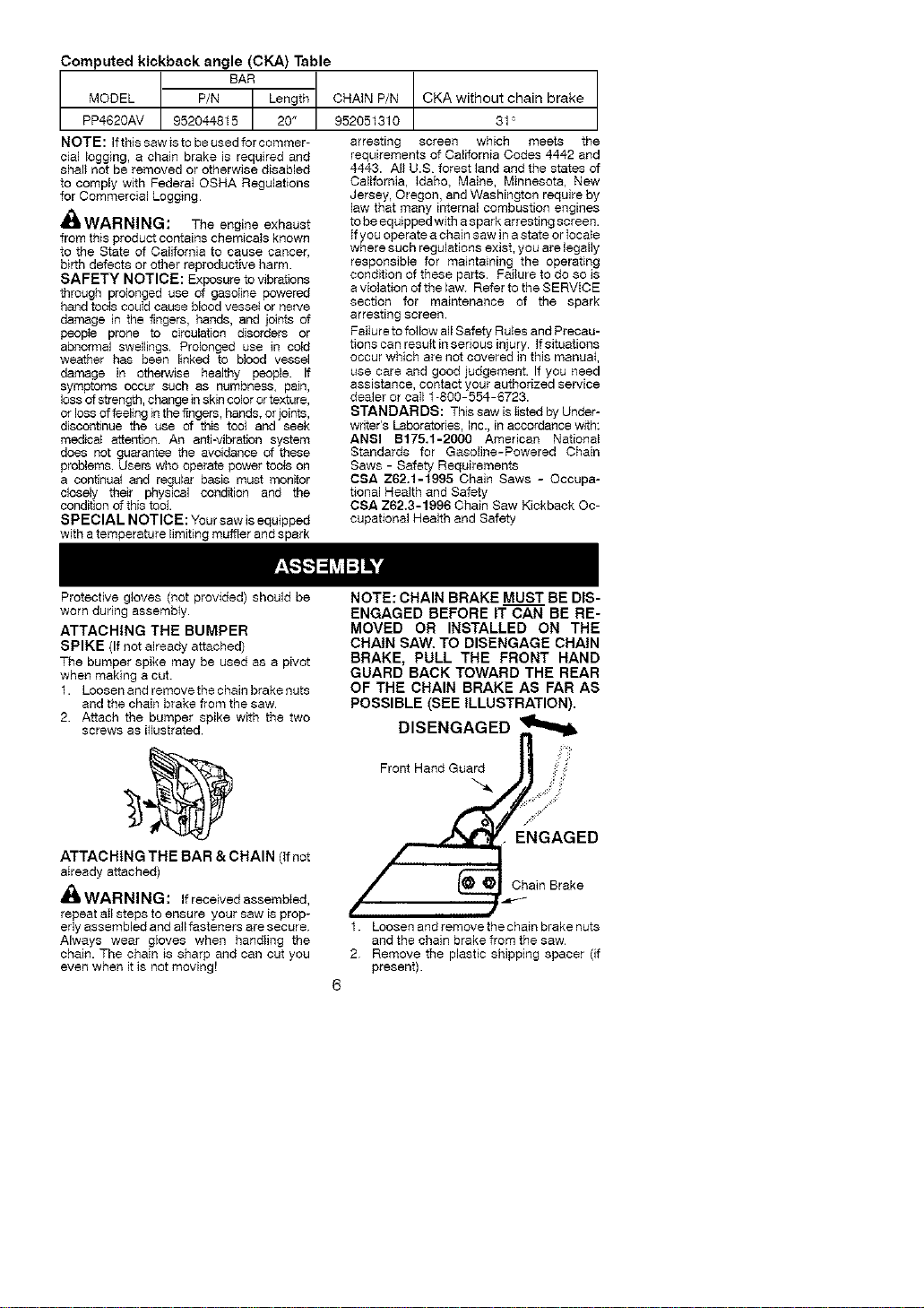
NOTE: CHAIN BRAKE MUST BE DIS-
ENGAGED BEFORE IT CAN BE RE-
MOVED OR INSTALLED ON THE
CHAIN SAW. TO DISENGAGE CHAIN
BRAKE, PULL THE FRONT HAND
GUARD BACK TOWARD THE REAR
OF THE CHAIN BRAKE AS FAR AS
POSSIBLE (SEE ILLUSTRATION).
DISENGAGED _
Front Hand Guard :
GAGED
/ _._Chatn Brake
1. Loosen and remove the chain brake nuts
and the chain brake from the saw
2 Remove the plastic shipping spacer (if
present).
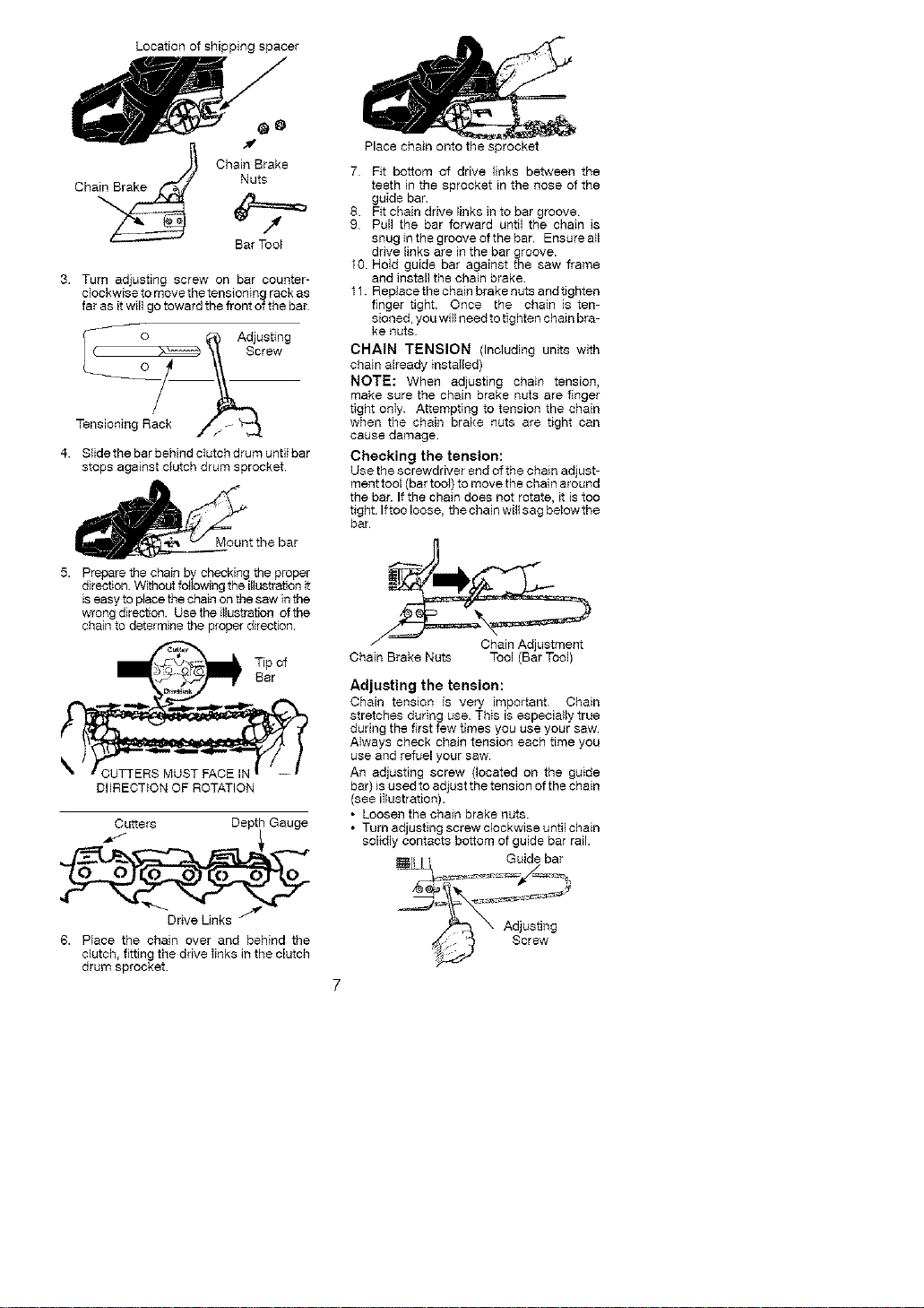
Locationofshippingspacer
a_ ChainBrake
Ch Nuts
BarTool
3.Turnadjustingscrewonbarcounter-
clockwisetomovethetensioningrackas
farasitwillgotowardthefrontofthebar
TensioningRac_k_
4. Slidethebarbehindclutchdrumuntilbar
stopsagainstclutchdrumsprocket.
5. Preparethechainbycheckingtheproper
direction.Withoutfollowingtheillustra_onit
iseasytoplacethechainonthesawinthe
wrongdirect_on.Usetheillustrationofthe
chaintodeterminetheproperdirection.
DIIRECTiONOFROTATION
Cutters DepthGauge
_DriveLinks
6. PIacethechainoverandbehindthe
clutch,fittingthedriveIinksintheclutch
drumsprocket
Placechainontothesprocket
7 Fitbottomofdrivelinksbetweenthe
teethinthesprocketinthenoseofthe
guidebar
8 Fitchainddvelinksintobargroove
9 Pullthebarforwarduntilthechainis
snuginthegrooveofthebar.Ensurea_l
drivelinksarein the bar groove.
10 Hold guide bar against the saw frame
and install the chain brake.
11. Replace the chain brake nuts and tighten
finger tight. Once the chain is ten-
sioned, you will need to tighten chain bra-
ke nuts.
CHAIN TENSION (Including units with
chain already installed)
NOTE: When adjusting chain tension,
make sure the chain brake nuts are finger
tight only. Attempting to tension the chain
when the chain brake nuts are tight can
cause damage.
Checking the tension:
Use the screwdriver end of the chain adjust-
ment tool (bar tool) to move the chain around
the bar. If the chain does not rotate, it is too
tight. Iftoo loose, the chain will sag below the
bar.
Chain Brake Nuts Tool (Bar Tool)
Adjusting the tension:
Chain tension is very important Chain
stretches during use. This is especially true
during the first few times you use your saw
Always check chain tension each time you
use and refuel your saw.
An adjusting screw (located on the guide
bar) is used to adjust the tens ion of the chain
(see illustration).
• Loosen the chain brake nuts.
• Turn adjusting screw clockwise until chain
solidly contacts bottom of guide bar rail.
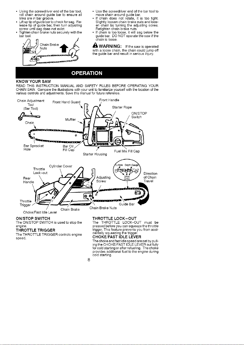
• Usingthescrewdriverendofthebartool,
rollchainaroundguidebartoensureall
linksareinbargroove.
• Liftuptipofguidebartocheckforsag.Re-
leasetipofguidebar,thenturnadjusting
screwuntiIsagdoesnotexist.
• T_ghtenchainbrakenutssecurelywiththe
bartool
ChainBrake
Nuts
KNOW YOUR SAW
• Use the screwdriver end of the bar toef to
move chain around guide bar.
• If chain does not rotate, it is too tight
Slightly loosen chain brake nuts and IOOS-
ell chain by turning the adjusting screw
Retighten chain brake nuts
• If chain is too loose, it witl sag below the
guide bar. DO NOT operate the saw ifthe
chain is loose
_'WARNING: if the saw is operated
with a loose chain, the chain could jump off
the guide bar and result in serious injury.
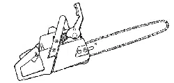
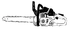
READ THIS INSTRUCTION MANUAL AND SAFETY RULES BEFORE OPERATING YOUR
CHAIN SAW. Compare the illustrations with your unit to familiarize yourself with tile location of tile
various contrefs and adjustments. Save this manual for future reference.
Chain Adjustment Front Hand Guard
(BarT,_olef) X_ r_ f_/
Muffler _/_
Hole Filt Cap
Starter Housing
Front Handle
Starter Rope
Fuet Mix FiII Cap
Throttle
Lock-out
Rear
Handle
Cylinder Cover
Adjusting
Direction
of Chain
Travel
Throttle
Chain Brake
Choke/Fast Idle Lever
ON/STOP SWITCH
The ON/STOP SWITCH is used to stop the
engine.
THROTTLE TRIGGER
The THROTTLE TRIGGER controls engine
speed.
Guide Bar
Chain Brake Nuts
THROTTLE LOCK-OUT
The THROTTLE LOCK-OUT must be
pressed before you can squeeze the throttle
trigger. This feature prevents you from acci-
dentally squeezing the trigger.
CHOKE/FAST IDLE LEVER
The choke and fast idle speed are set by pull-
ing the CHOKE/FAST IDLE LEVER out fulIy
for cold starting or after refue}ing. The choke
provides additiona_ fuel to the engine during
cefd starting.
CHAIN BRAKE
The CHAIN BRAKE is a device designed to
stop the chain if kickback occurs. The chain
brake activates automatically in the event of
kickback. The chain brake activates manu-
ally ffthe front hand guard is pushed forward.
The chain brake is disengaged by pulling the
front hand guard back toward the front han-
dle as far as possible.
CHAIN TENSION
_t is normal for a new chain to stretch during
first 30 minutes of operation. You should check
your chain tension frequently. See CHAIN
TENSION in the ASSEMBLY section.
WARN]NG: Muffler is very hot dur-
ing and after use. Do not touch the muffler or
allow combustible matedal such as dry
grass or fuel to do so
BEFORE STARTING ENGINE
_ll WARNING: Be sure to read the fuet
handling information in the safety rules sec-
tion of this manual before you begin. If you do
not understand the fuel handling information
do not attempt to fuel your unit. Seek help
from someone that does understand the in-
formation or calI the customer assistance
help Iine at t-800-554-6723
FUELING ENGINE
_ItWARNING: Remove fuel cap stow-
ly when refueling.
FUELING ENGINE
This engine is certified to operate on
unleaded gasoline. Before operation,
gasoline must be mixed with a good quality
synthetic 2-cycle air-coefed engine oil
designed to be mixed at a ratio of 40:1.
Poulan/WEED EATER brand synthetic oil is
recommended. Mix gasoline and oil at a ratio
of40:f A40:1 ratioisobtainedbymixing32
ounces of oil with 1 gallon of unleaded
gasefine. Included with this saw is a 32
ounce container of oil. Pour the entire
contents of this container into 1 gallon of
gasefine to achieve the proper fuel mixture.
DO NOT USE automotive oil or boat oil These
oiIs will cause engine damage When mixing
fuel, feflow instructions printed on container.
Once oil is added to gasoline, shake container
momentarily to assure that the fuel is
thoroughIy mixed. AM,ays read and follow the
safety rules relating to fuel before fueling your
unit.
BAR AND CHAIN LUBRICATION
The bar and chain require continuous lubri-
cation. Lubrication is provided by the auto-
matic oiler system when the oil tank is kept
filled. Lack of oil will quickly ruin the bar and
chain. Too little oil will cause overheating
shown by smoke coming from the chain and/
or disceforation of the bar.
In freezing weather oil will thicken, making it
necessary to thin bar and chain oiI with a
small amount (5 to 10%) of #1 Diesef Fuel or
kerosene Bar and chain oil must be free
flowing for the oil system to pump enough oiI
for adequate lubrication.
Genuine Poulan or Poulan PRO bar and
chain oil is recommended to protect your unit
against excessive wear from heat and
friction. Poulan or Poulan PRO oil resists
high temperature thinning. If PouIan or
Poulan PRO bar and chain oil is not
available, use a good grade SAE 30 oil
• Never use waste oil for bar and chain tubd-
cation.
• Always stop the engine before remowng
the oit cap.
IMPORTANT
Experience indicates that alcohol-blended
fuels (called gasohol or using ethanol or
methanol) can attract moisture which leads
to separation and formation of acids during
storage. Acidic gas can damage the fuef
system of an engine whiIe in storage To
avoid engine problems, the fuel system
should be emptied before storage for 30
days or longer. Drain the gas tank, start the
engine and let it run until the fuel lines and
carburetor are empty Use fresh fuel next
season. See STORAGE section for addi-
tional information.
CHAIN BRAKE
Ensure chain brake is disengaged by pulling
the front hand guard back toward the front han-
dle as far as possible. The chain brake must be
disengaged before cutting with the saw.
_iI,WARNING: The chain must not
move when the engine runs at idle speed, if
the chain moves at idle speed refer to CAR-
BURETOR ADJUSTMENT within this
manual. Avoid contact with the muffler. A hot
muffler can cause serious burns.
To stop the engine move the ON/STOP
switch to the STOP position.
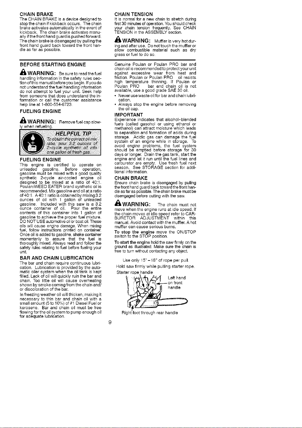
To start the engine hold the saw firmty on the
ground as illustrated Make sure the chain is
free to turn without contacting any object.
Use only 15"- 18" of rope per puII
Hold saw firmly while pulling starter rope
Starter rope handle
Lefthand
• On front
Right foot through rear handle
IMPORTANT POINTS TO REMEMBER
When pulling the starter rope, do not use tile fulI
extent of the rope as this can cause the rope to
break. Do not let starter rope snap back. Hold
the handle and let the rope rewnd slowly.
For cold weather starting, start the unit at
FULL CHOKE; a]tow the engine to warm up
before squeezing the throtfte tr[gge£
NOTE: Do not cut material with the choke/
fast idle lever at the FULL CHOKE position.
STARTING A COLD ENGINE (or warm
engine after running out of fuel):
NOTE: in the following steps, when the
choke/fast idle lever is pulled out to the full
extent, the correct throtpe setting for starting
is set automaticalIy.
1. Move ON/STOP switch to the ON posi-
tion.
2. Puilthe choke/fast idte lever out to the full
extent (to the FULL CHOKE position).
3. Pull starter rope quickly with your right
hand a maximum of f Otimes. Then, pro-
ceed to the next step.
NOTE: If the engine sounds as if it is trying
to start before the 10th pull, stop pulling and
immediately proceed to the next step
4-. Push the choke/fast idle lever in to the
HALF CHOKE position.
5. Puff the starter rope quickly with your
right hand until the engine starts.
6. Allow the engine to run for approximately
30 seconds. Then, squeeze and release
throttle trigger to allow engine to return to
idle speed.
TOP SWITCH
CHOKE/FAST IDLE LEVER
FULL HALF OFF"-_,_L__
STARTING A WARM ENGINE
1. MoveON/STOP switchtothe ONpos_on.
2. Pull the choke/fast idle lever out to the
HALFCHOKE pos_on.
3. Pull the starter rope quickly w_th your right
hand until the engine starts.
4. Squeeze and release the throttle trigger
to allow engine to return to idle speed.
DIFFICULT STARTING (or 8tatting a
flooded engine)
The engine may be flooded if ithas not started
after 10 puils.
Flooded engines can be cleared of excess f_el
by following the warm engine starting proce-
dure listed above. Ensure the ON/STOP
switch is in the ON position.
Starting could require many pulls depending on
how badly unit is flooded, if engine still fails to
start, refer to TROUBLESHOOTING TABLE
or call 1-800-554-8723.
CHAIN BRAKE
_tL WARNING: _fthe brake band is worn
too thin it may break when the chain brake is
triggered. With a broken brake band, the chain
brake will not stop the chain. The chain brake
should be replaced by an authorized service
denier if any part is worn to less than 0.020"
(05 mm) thick. Repairs on a chain brake
should be made by an authorized service deal-
er. Take your unit to the place of purchase if
purchased from a servicing dealer, or to the
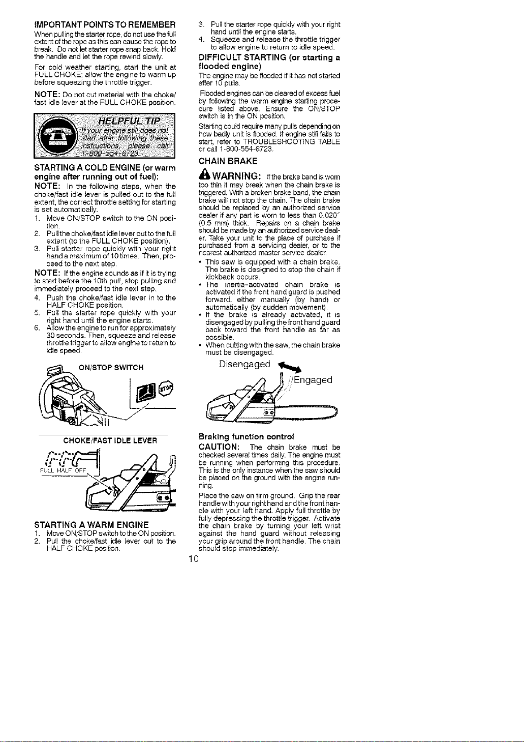
nearest authorized master service dealer.
• This saw is equipped with a chain brake
The brake is designed to stop the chain if
kickback occurs
• The inertia-activated chain brake is
activated if the front hand guard is pushed
forward, either manually (by hand) or
automatically (by sudden movement}
• If the brake is already activated, it is
disengaged by pulling the front hand guard
back toward the front handle as far as
possible
• When cutting with the saw, the chain brake
must be disengaged
Disengaged
Braking function control
CAUTION: The chain brake must be
checked several times daily. The engine must
be running when performing this procedure
This is the only instance when the saw should
be placed on the ground with the engine run-
ning.
PIace the saw on firm ground. Grip the rear
handle with your right hand and the front han-
dle with your left hand. Apply full throttle by
fully depressing the throttle trigger Activate
the chain brake by turning your left wrist
against the hand guard without releasing
your grip around the front handle The chain
should stop immediately
10
Inertia activating function control
WARNING: When performing the
folfawing procedure, the engine must be
turned off.
Gdp the rear handSe with your dght hand end
the front handle with your left hand. Hold the
IMPORTANT POINTS
chain sew approximately 14" (35 cm) above
a stump or other wooden surface. Release
your grip on the front handle and use the
weight of the saw to let the tip of the guide bar
fall forward and contact the stump. Whenthe
tip of the bar hits the stump, the brake should
activate
• Check chain tension before first use and
after f minute of operation. See CHAIN
TENSION in the ASSEMBLY section.
• Cut wood only. Do not cut metal, plastics,
masonry, non-wood buJIding materials,
etc.
• Stop the saw ff the chain strikes a foreign
object, inspect the saw and repair or re-
place parts as necessary.
• Keep the chain out of dirt and sand Even a
small amount of dirt will quickly duiI a chain
and thus increase the possibility of kickback.
• Practice cutting a few small fags using the
fo_fawing techniques to get the "feel" of us-
ing your saw before you begin a major
sawmg operation.
• Squeeze the thro_e trigger and allow the
engine to reach fuII speed before cut_ng.
• Begin cutting with the saw frame
against the fag.
• Keep the engine at furl speed the entire
time you are cutting.
•AIIow the chain to cut for you. Exert only
light downward pressure. If you force
the cut, damage to the bar, chain, or en-
gine can result.
• Release the throttle trigger as soon as
the cut is completed, alfawing the en-
gine to idIe If you run the saw at full
throttle without a cutting Iced, unneces-
sary wear can occur to the chain, bar,
and engine
• To avoid fasing control when cut is com-
plete, do not put pressure on saw at end
of cut.
• Stop the engine before setting the saw
down after cutting.
THEE FELLING TECHNIQUES
_I'WARNING: Check for broken or
dead branches which can fall while cutting
causing serious injury. Do not cut near build-
ings or electhcal wires if you do not know the
direction of tree fall, nor cut at night sface you
wiII not be ale to see weli, nor during bad
weather such as rafa_ snow, or strong winds,
etc. if the tree makes contact with any utility
line, the utility company should be notified
immediately.
• Carefully plan your sawing operation in ad-
vance.
• Cleartheworkarea Youneedacfaararea
all around the tree so you can have secure
footing
• Study the natura_ conditions that can cause
the tree to falI in e particular direction.
Natural conditions that can cause a tree to
fall in e particular direction include:
• The wind direction and speed
• The Iean of the tree. The faan of a tree
might not be apparent due to uneven or
slopfag terrafa Use a plumb or level to de-
termfae the direction of tree lean.
• Weight and branches on one side.
• Surrounding trees and obstacles
Look for decay and rot. if the trunk is rotted,
it can snap and fall toward the operator
Check for broken or dead branches which
can fall on you while cutting.
Make sure there is enough room for the tree to
fall Maintain a distance of 2 1/2 tree lengths
from the nearest person or other objects En-
gine noise can drown out a warning ca$
Remove dirt, stones, loose bark, nails, sta-
ples, and wire from the tree where cuts are to
be made.
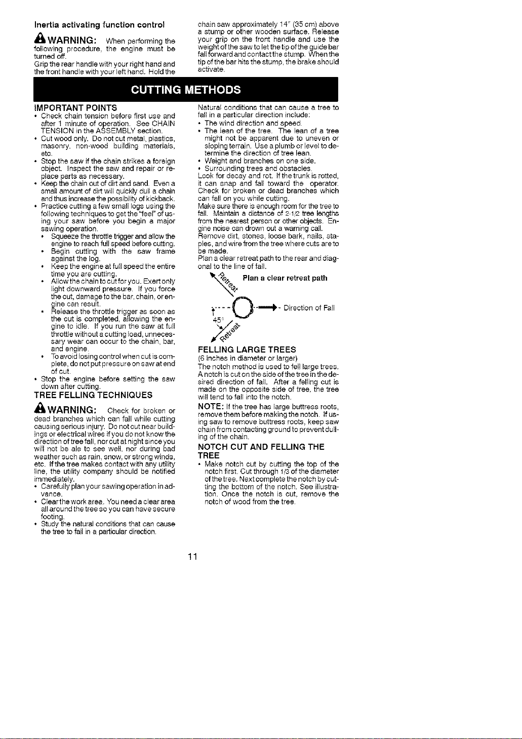
Plan a clear retreat path to the rear and diag-
onal to the line of fall
_x_e_. Plan clear retreat
a
path
_'" _ - L_'"_ - Direction of Fall
45 _
FELLING LARGE TREES
(6 inches in diameter or larger)
The notch method is used to felt large trees
A notch is cut on the side of the tree in the de-
sired direction of fall. After a felIing cut is
made on the opposite side of tree, the tree
will tend to fall into the notch.
NOTE: If the tree has large buttress roots,
remove them before making the notch, if us-
ing saw to remove buttress roots, keep saw
chain from contacting ground to prevent dull-
ing of the chain.
NOTCH CUT AND FELLING THE
TREE
• Make notch cut by cutting the top of the
notch first Cut through 1/3 of the diameter
of the tree. Next complete the notch by cut-
ting the bottom of the notch. See illustra-
tion. Once the notch is cut, remove the
notch of wood from the tree
11
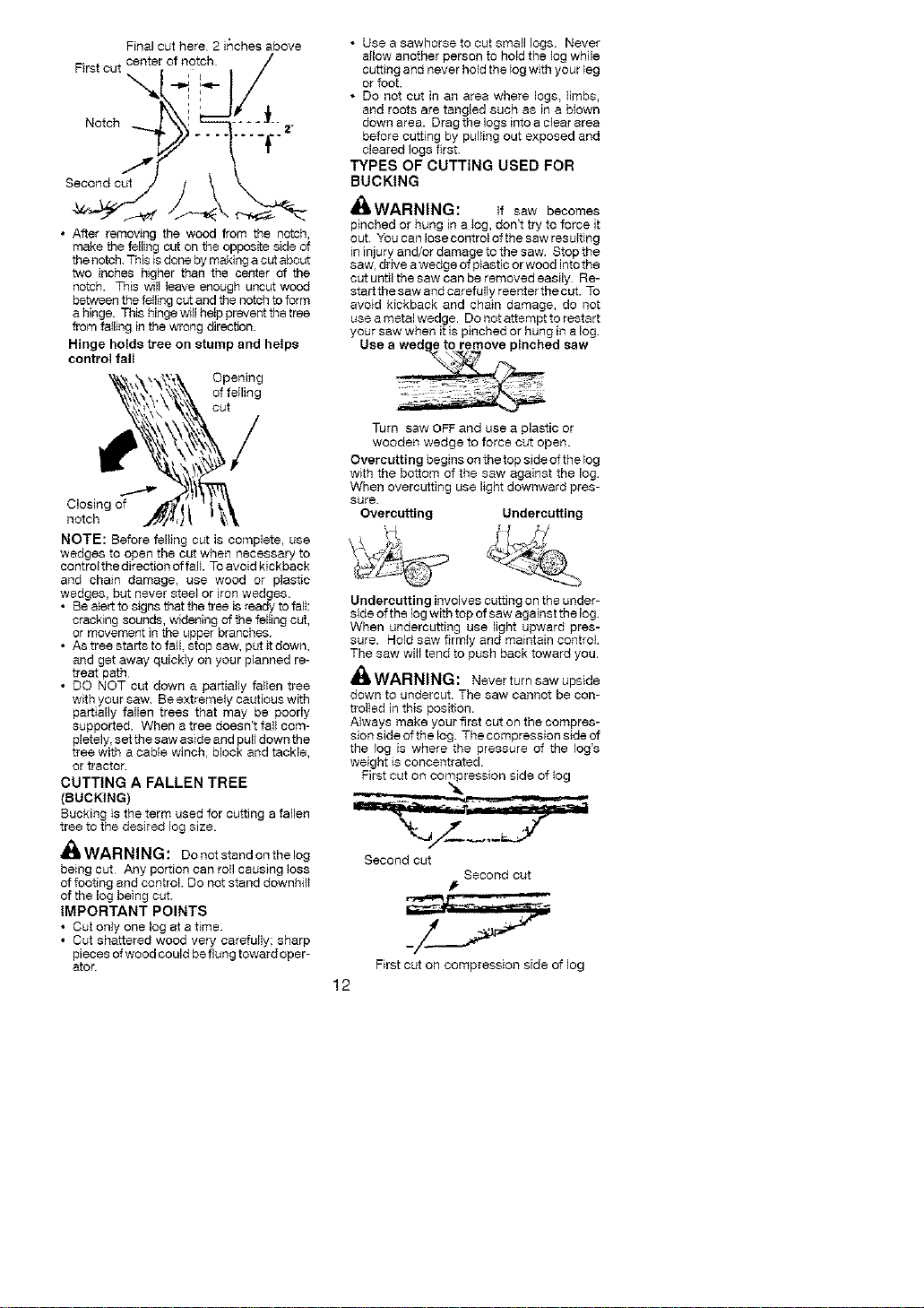
Final cut here 2 inches above
First cut center of notch
K\', .' _# I
• After removing the wood from the notch,
make the felling cut on the opposifa side of
the notch. This is done by making a cut about
two inches higher than the center of the
notch. This wilI leave enough uncut wood
between the failing cut and the notch to form
a hinge. This hinge will help prevent the tree
from falling in the wrong direction.
Hinge holds tree on stump and helps
control fall
Opening
of failing
out
Closing of
notch
NOTE: Before felling cut is complete, use
wedges to open the cut when necessary to
control the direction of fall. To avoid kickback
and chain damage, use wood or plastic
wedges, but never steel or iron wedges.
• Be alert to signs that the tree is ready to fall:
cracking sounds, widening of the felling cut,
or movement in the upper branches.
• As tree starts to fall. stop saw, put it down,
and get away quickly on your planned re-
treat path
• DO NOT cut down a partially fallen tree
with your saw. Be extremely cautious with
partially fallen trees that may be poorly
supported. When a tree doesn't fall com-
pletely, set the saw aside and pull down the
tree with a cable winch, block and tackle,
or tractor.
CUTTING A FALLEN TREE
(BUCKING)
Bucking is the term used for cutting a fallen
tree to the desired log size
_ WARNING: Do not stand on thelog
being cut Any portion can roll causing loss
of footing and control. Do not stand downhil_
of the log being cut.
IMPORTANT POINTS
• Cut only one log at a time.
• Cut shattered wood very carefully; sharp
pieces of wood could be flu ng toward oper-
ator.
• Use a sawhorse to cut small logs. Never
allow another person to hold the log while
cutting and never hold the log with your _eg
or foot.
• Do not cut in an area where logs, limbs,
and roots are tangled such as in a blown
down area. Drag the logs into a clear area
before cutting by pulling out exposed and
cleared logs first.
TYPES OF CUTTING USED FOR
BUCKING
_I_,WARNING: if saw becomes
pinched or hung in a Ieg, don't try to force it
out. You can lose control of the saw resulting
in injury and/or damage to the saw. Stop the
saw, drive a wedge of ptastic or wood into the
cut until the saw can be removed easily Re-
start the saw and carefully reenter the cut. To
avoid kickback and chain damage, do not
use a metal wedge. Do not attempt to restart
your saw when it is pinched or hung in a log.
Use a wed e to remove pinched saw
Turn
saw OFF and use a plastic or
wooden wedge to force cut open.
Overcutting begins on the top side of the tog
with the bottom of the saw against the log.
When overcutting use light downward pres-
sure.
Overcutting Undercutting
Undercutting involves cutting on the under-
side of the log with top of saw against the log.
When undercutting use light upward pres-
sure. Hold saw firmly and maintain control.
The saw will tend to push back toward you.
_,WARNING: Never turn saw upside
down to undercut. The saw cannot be con-
trolled in this position.
Always make your first cut on the compres-
sion side of the log. The compression side of
the log is where the pressure of the log's
weight is concentrated.
First cut on comi_ression side of log
Second out
Second cut
First cut on compression side of log
12
BUCKING WITHOUT A SUPPORT
• Overcut through 1/3 of the diameter of the
log.
• Roll the log over and finish with a second
overcut.
• Watch for _ogswith a compression side to
prevent the saw from pinching. See il-
lustrations for cutting logs with a compres-
sion side.
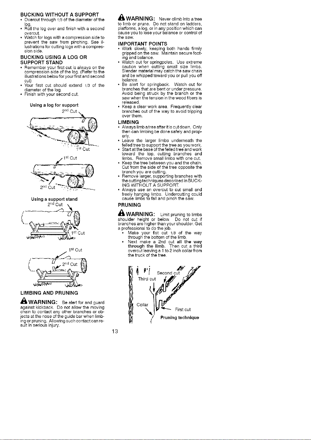
BUCKING USING A LOG OR
SUPPORT STAND
• Remember your first cut is always on the
compression side of the log. (Refer to the
illustrations below for your first and second
cut)
• Your first cut should extend 1/3 of the
diameter of the log.
• Finish with your second cut.
Using a log for support
2_d Cut
1st Cut
j 1st Cut
Using a support stand
. 2 nd Cut k
cut
1st Cut
L iy
LIMBING AND PRUNING
,_ WARNING: Be alert for and guard
against kickback. So not allow the moving
chain to contact any other branches or ob-
jects at the nose of the guide bar when limb-
ing or pruning. Allowing such contact can re-
sult in serious injury
_i_ WARNING: Never climb into a tree
to limb or prune Do not stand on ladders,
platforms, a log, or in any position which can
cause you to lose your balance or control of
the saw.
IMPORTANT POINTS
• Work slowly, keeping both hands firmly
gripped on the saw Maintain secure foot-
mg and balance.
• Watch out for spbngpoles. Use extreme
caution when cutting small size limbs
Slender matedal may catch the saw chain
and be whipped toward you or pull you off
balance.
• Be alert for spdngback. Watch out for
branches that are bent or under pressure.
Avoid being struck by the branch or the
saw when the tension in the wood fibers is
released.
• Keep a clear work area Frequently clear
branches out of the way to avoid tripping
over them.
LtMBING
• Alwayslimbatreeafferitiscutdown. Only
then can limbing be done safely and prop-
erly
• Leave the larger limbs underneath the
felled tree to support the tree as you work
• Start at the base of the felled tree and work
toward the top, cutting branches and
_imbs. Remove small limbs with one cut.
• Keep the tree between you and the chain.
Cut from the side of the tree opposite the
branch you are cutting.
• Remove larger, supporting branches with
the cutting techniques described in SUCK-
ING WITHOUT A SUPPORT.
• Always use an overcut to cut small and
freely hanging limbs. Undercutting could
cause _imbs to fall and pinch the saw.
PRUNING
_,WARNING: Limit pruning to limbs
shoulder height or below Do not cut if
branches are higher than your shoulder Get
a professional to do the job.
• Make your fist cut 1/3 of the way
through the bottom of the limb
• Next make a 2nd cut all the way
through the limb. Then cut a third
overcut leaving a 1 to 2 inch cotlar from
the truck of the tree.
i' _jr _ •
,I seoondcut"/'/
Third es_it_/
Collar _ First cut
_/ Pruning technique
13
_I'WARNING: Disconnectthespark
plug before performing maintenance except
for carburetor adjustments.
We recommend all service and adjustments
not listed in this manual be performed by an
authorized service dealer.
HE_ #FULTI#
_ rep_irs#_
:desCribe(
_ny de_fer _ther th
_p_ir_: unde wa ta_
_erai_i_ten_ce
MAINTENANCE SCHEDULE
Check:
Fuel mixture level .... Before each use
Bar lubrication ....... Before each use
Chain tension ....... Before each use
Chain sharpness .... Before each use
For damaged parts . Before each use
For loose caps ...... Before each use
For loose fasteners . . Before each use
For loose parts ...... Before each use
Inspect and Clean:
Bar ................ Before each use
Complete saw ....... After each use
Air filter ............. Every 5 hours*
Chain brake ........ Every 5 hours*
Spark arresting screen
and muffler ......... Every 25 hours*
Replace spark plug . Yearly
Replace fuel filter.. Yearly
Hours of Operation
AIR FILTER
CAUTION: Do not clean filter in gasoline
or other flammable solvent to avoid creating
a fire hazard or producing harmful evapora-
tive emissions.
Cleaning the air filter:
A dirty air filter decreases engine perform-
ance and increases fuet consumption and
harmful emissions. Always clean after 15
tanks of fuel or 5 hours of operation, which-
ever comes first. Clean more frequently in
dusty conditions. A used sire fiIter can never
be completely cleaned It is advisable to re-
pIace your air filter with a new one affer every
50 hours of operation, or annuaIly, whichever
comes first.
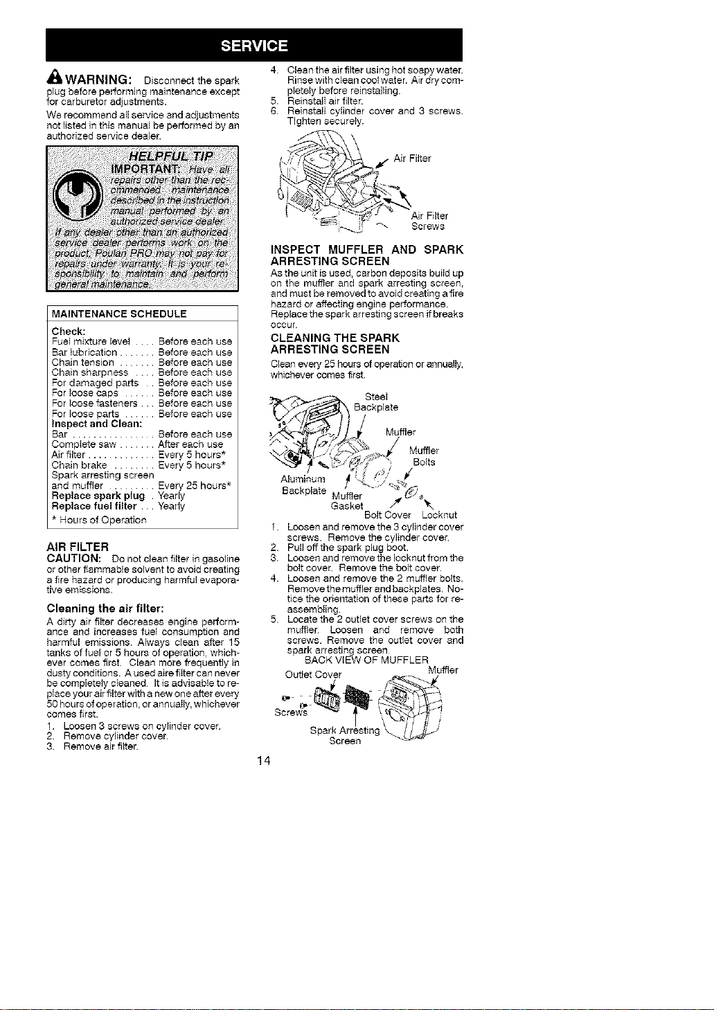
1. Loosen 3 screws on cylinder cover
2. Remove cylinder cover.
3. Remove air filter.
4. Clean the air filter using hot soapy water.
Rinse with clean cool water. Air dry com-
plete}y before reinstalling
5. ReinstalI air filter.
6 ReinstalI cylinder cover and 3 screws
Tighten securely.
Air Filter
INSPECT MUFFLER AND SPARK
ARRESTING SCREEN
As the unit is used, carbon deposits build up
on the muffler and spark arresting screen,
and must be removed to avoid creating a fire
hazard or affecting engine performance.
Replace the spark arresting screen if breaks
occur
CLEANING THE SPARK
ARRESTING SCREEN
Clean every 25 hours of operation or annually,
whichever comes first.
SteeI
Backplate
Muffler
Muffler
BoIts
Aluminum _ _/
Backplate Muffler
Gasket
Bolt Cover Locknut
f. Loosen and remove the 3 cylinder cover
screws Remove the cylinder cover
2 Pull off the spark plug boot.
3. Loosen and remove the Iocknut from the
bolt cover. Remove the bolt cover.
4. Loosen and remove the 2 m_ler bolts.
Remove the muffler and backplates. No-
tice the orientation of these parts for re-
assembling.
5 Locate the 2 outlet cover screws on the
muffler Loosen and remove both
screws Remove the outlet cover and
spark arresting screen
BACK ViEW OF MUFFLER
Oufiet Cover Muffier
SparkscreenArresting_._._Ji / _'
14
6. Ctean the spark arresting screen with a
wire brush. Replace screen if any wkes
are broken or screen is blocked after
cleaning.
7. Reinstall spark arresting screen.
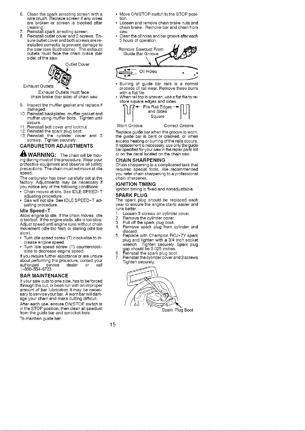
8. ReinstalI ouifet cover and 2 screws. En-
sure outlet cover and both screws are re-
installed correctly to prevent damage to
the saw (see illustrations). The exhaust
outlets must face the chain brake (bar
side) of the saw.
Exhaust Outl_ utlet Cover
Exhaust Outlets must face
chain brake (bar side) of chain saw
9. lnspect the muffler gasket and replace if
damaged.
10. Reinstall backplates, muffler gasket and
muffler using muffter bolts. Tighten until
secure
11. Reinstall bolt cover and Iocknut.
12. Reinstall the spark plug boot.
13. Reinstall the cylinder cover and 3
screws. Tighten securely
CARBURETOR ADJUSTMENTS
_k WARNING: The chain will be mov-
ing during most of this procedure Wear your
protective equipment and observe all safety
precautions. The chain must not move at idle
speed.
The carburetor has been carefully set at the
factory. Adjustments may be necessary if
you notice any of the following conditions:
• Chain moves at idle. See IDLE SPEED-T
adjusting procedure.
• Saw will not idle. See IDLESPEED-T ad-
justing procedure.
Idle Speed-T
Allow engine to idle If the chain moves, idle
is too fast. If the engine stal_s, idle is too slow.
Adjust speed until engine runs without chain
movement (idle too fast) or stalling (idle too
slow).
• Turn idle speed screw (T) clockwise to in-
crease engine speed.
• Turn idte speed screw (T) counterclock-
wise to decrease engine speed.
If you require further assistance or are unsure
about performing this procedure, contact your
authorized service dealer or call
1-800-554-6723
BAR MAINTENANCE
If your saw cuts to one side, has to be forced
through the cut, or been run with an improper
amount of bar Iubricapen it may be neces-
saryto serviceyour bar A worn bar will dam-
age your chain and make cutting difficult.
After each use, ensure ON/STOP switch is
in the STOP position, then clean all sawdust
from the guide bar and sprocket hole
To maintain guide bar:
• Move ON/STOP switch to the STOP posi-
tion.
• Loosen and remove chain brake nuts and
chain brake Remove bar and chain from
saw
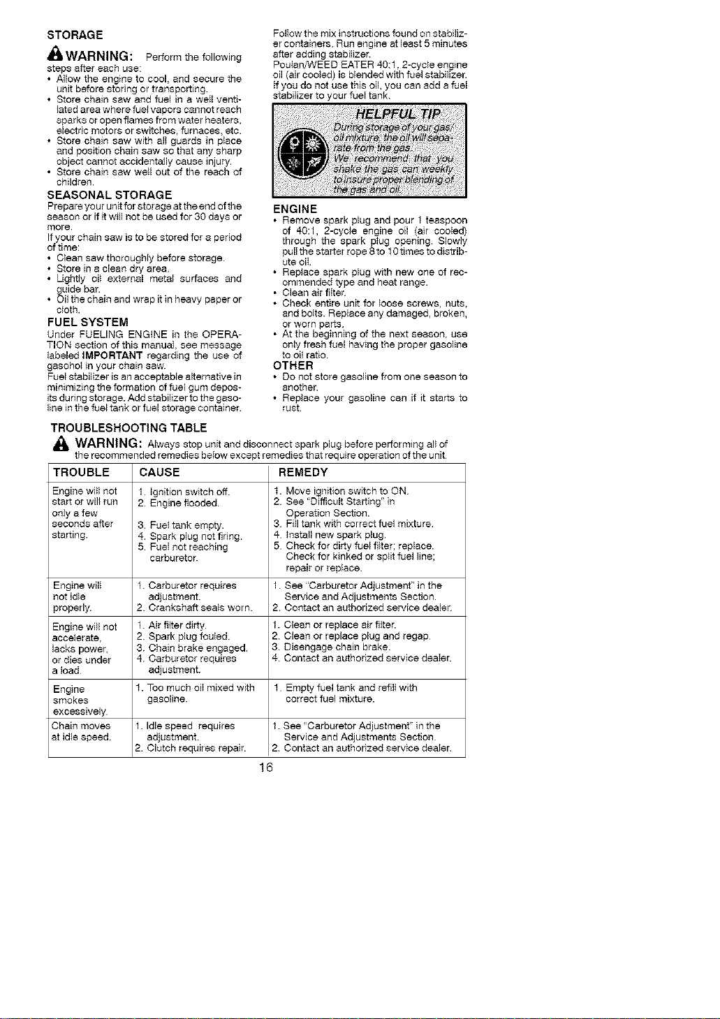
• Clean the oil holes and bar groove after each
5 hours of operation
Remove Sawdust Prom
Guide Bar G_o_
Oi} So,as ,
• Burring of guide bar rails is a normal
process of rail wear. Remove these burrs
with a flat file.
• When rail top is uneven, use a flat file to re-
store square edges and sides.
TL_ _ File Rail Edges _ rL[]
and Sides
Square
Worn Groove Correct Groove
Replace guide bar when the groove is worn,
the guide bar is bent or cracked, or when
excess heating or burbng of the rails occurs.
if replacement is necessary, use only the guide
bar specified for your saw in the repair parts list
or on the decal located on the chain saw
CHAIN SHARPENING
Chain sharpening is a complicated task that
requires special tools. We recommended
you refer chain sharpening to a professional
chain sharpener.
IGNITION TIMING
_gnition timing is fixed and nonadjustable
SPARK PLUG
The spark plug should be replaced each
year to ensure the engine starts easier and
runs better.
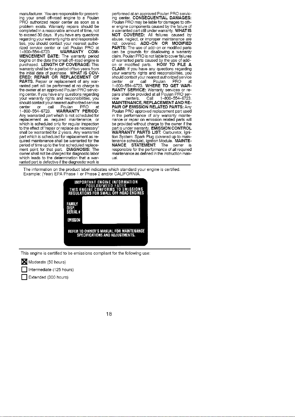
1. Loosen 3 screws on cylinder cover.
2. Remove the cylinder cover.
3. PulI off the spark plug boot.
4. Remove spark plug from cylinder and
discard.
5. Replace with Champion RCJ-7Y spark
plug and tighten with a 3/4 inch socket
wrench. Tighten securely. Spark p_ug
gap should be 0.025 inches
6 Reinstallthe spark plug boot.
7 Reinstallthe cylinder cover and 3 screws
Tighten secure}y.
Spark Plug Soot
15
STORAGE
_ILWARNING: Perform the following
steps after each use:
• AHow the engine to cool, and secure the
unit before storing or transporting
• Store chain saw and fuel in a weII venti-
lated area where fuel vapors cannot reach
sparks or open flames from water heaters,
electric motors or switches, furnaces_ etc.
• Store chain saw with all guards in place
and position chain saw so that any sharp
object cannot accidentally cause injury.
• Store chain saw well out of the reach of
children.
SEASONAL STORAGE
Prepare your unit for storage at the end of the
season or if itwill not be used for 30 days or
more
If your chain saw is to be stored for a period
of time:
• Clean saw thorougMy before storage.
• Store in a clean dry area.
• Lightly oi_ external metal surfaces and
guide bar.
• Oil the chain and wrap it in heavy paper or
cloth.
FUEL SYSTEM
Under FUELING ENGINE in the OPERA-
TION section of this manual, see message
labeled IMPORTANT regarding the use of
gasohot in your chain saw.
Fuel stabilizer is an acceptable alternative in
minimizing the formation of fuel gum depos-
its du ring storage. Add stabilizer to the gaso-
line in the fuel tank or fuel storage container.
FolIow the mix instructions found on stabiliz-
er containers Run engine at least 5 minutes
after adding stabilizer.
Poutan/WEED EATER 40:1,2-cyc}e engine
oil (air cooled) is blended with fuel stabilizer.
If you do not use this oil, you can add a fuel
stabilizer to your fuel tank
ENGINE
• Remove spark plug and pour 1 teaspoon
of 40:1, 2-cyc}e engine oil (air cooled)
through the spark p_ug opening. Slowly
pull the starter rope 8 to 10 times to distrib-
ute oil
• Replace spark plug with new one of rec-
ommended type and heat range.
• Clean air flItah
• Check entire unit for loose screws, nuts,
and boIts. Replace any damaged, broken,
or worn parts
• At the beginning of the next season, use
only fresh fuel having the proper gasoline
to oil ratio
OTHER
• DO not store gasoline from one season to
another.
• Replace your gasoline can if tt starts to
rust.
TROUBLESHOOTING TABLE
A(_ WARNING: Always stop unit and disconnect spark plug before perforPning all of
the recommended remedies below except remedies that require operation of the unit
TROUBLE CAUSE REMEDY
Engine wiil not 1. Ignition sw_tch off. t. Move ignition switch to ON
start or wi]I run 2. Engine flooded. 2 See "Difficult Starting" in
oniy a few Qperaflon Section.
seconds after 3. Fue} tank empty. 3 Fill tank with correct fuel mixture
starting. 4. Spark plug not firing 4- tnstall new spark plug.
5. FueI not reaching 5 Check for dirty fuel filter; replace.
carburetor. Check for kinked or sp_it fuel line;
repair or replace
Engine wilI 1. Carburetor requires 1. See "Carburetor Adjustment" in the
not idle adjustment Service and Adjustments Section.
properly. 2 Crankshaft seals worn 2. Contact an authorized service dealer
Engine witl not 1. Air flker dirty. 1. Clean or replace air flitar.
acceIerata, 2. Spark plug fouled. 2 Clean or replace plug and regap
lacks power, 3. Chain brake engaged. 3 Disengage chain brake
or dies under 4-. Carburetor requires 4 Contact an authorized service denier.
a load adjustment.
Engine f. Too much oiI mixed with f Empty fuel tank and refllI with
smokes gasoline correct fuel mixture.
excessively
Chain moves 1. Idle speed requires 1. See "Carburetor Adjustment" in the
at idle speed, adjustment. Service and Adjustments Section
2. Clutch requires repair. 2. Contact an authorized service dealer
16

PoulanPRO,adivisionofHusqvamaOut-
doorProductsInc.,warrantstotheobgioal
consumerpurchaserthateachnewPoulan
PRObrandgasolinechainsawisfreefrom
defectsinmaterialandworkmanshipand
agreestorepairorreplaceunderthiswar-
raofyanydefectivegasolinechainsawas
fefIowsfromtheodgioaIdateofpurchase.
2YEARS- PartsandLabor,whenusedfor
householdpurposes.
60DAYS- PartsandLabor,whenusedfor
commercial,professional,orincomepro-
ducingpurposes
30DAYS-PartsandLabor,if used for rental
purposes
This warranty is not transferable and does
not cover damage or liability caused by im-
proper handling, improper maintenance or
a{teration, or the use of accessories and/or
attachments not speciflcafly recommended
by Poulan PRO for this chain saw This war-
ranty does not cover tune-up, spark plugs,
filters, starter ropes, chain sharpening, bars,
chains, and other parts which wear and re-
quire repIacement with reasonable use dur-
ing the warranty period This warranty does
not cover predelivery setup, instalIation of
guide bar and chain, and normal adjust-
ments explained in the instruction manual
such as chain tension adjustments. This
warranty does not cover transportation
costs.
In the event you have a efaim under this war-
ranty, you must return the product to an au-
thorized service dealer.
SpeuId you have any unanswered questions
concerning this warranty, please contact:
Poulan PRO, a division of
Husqvarna Outdoor Products inc.
1030 Stevens Creek Road
Augusta, GA 30907
1-800-554-6723
In Caneda_ contact:
Poulan PRO
5855 Terry Fox Way
Mississauga,Ontaed LSV3E4
Giving the model number, serial number and
date of purchase of your product and the
name and address of the authorized dealer
from whom it was purchased.
THiS WARRANTY GIVES YOU SPECIFIC
LEGAL RIGHTS, AND YOU MAY HAVE
OTHER RIGHTS WHICH VARY FROM
STATE TO STATE.
NO CLAIMS FOR CONSEQUENTIAL OR
OTHER DAMAGES WiLL BE ALLOWED,
AND THERE ARE NO OTHER EXPRESS
WARRANTIES EXCEPT THOSE EX-
PRESSLY STIPULATED HEREIN.
SOME STATES DO NOT ALLOW LIMITA-
TIONS ON HOW LONG AN IMPUEDWAR-
RANTY LASTS OR THE EXCLUSION OR
LiMITATiONS OF INCIDENTAL OR CON-
SEQUENTIAL DAMAGES, SO THE
ABOVE LIMITATIONS OR EXCLUSION
MAY NOT APPLY TO YOU.
This is a limited warranty within the meaning
of that term as defined in the Magnuson-
Moss Act of 1975.
The policy of Poulan PRO is to contiouousIy
improve its products Therefore, Poulan
PRO reserves the right to change, modify, or
discontinue medals, designs, specifications,
and accessories of ali products at any time
without notice or obligation to any purchaser
YOUR WARRANTY RIGHTS AND OBLIGA-
TIONS: The U S. Environmental Protection
Agency, Environment Canada and Poulan
PRO are pleased to explain the emissions con-
trol system warranty on your year 2007 and lat-
er small off-road engine. Poulan PRO must
warrant the emission control system on your
smal_ off-road engine for the periods of time
listed below provided there has been no abuse,
neglect, or improper maintenance of your small
off-road engine. Your emission control system
iocludes parts such as the carburetor and the
ignition system. Where a warrantable condition
exists, Poulan PRO will repair your small off-
road engine at no cost to you. Expenses cov-
ered under warranty include diagnosis, parts
and labor. MANUFACTURER'S WARRAN-
TY COVERAGE: If any emissions related part
on your engine (as listed under Emissions
Control Warranty Parts Ust) is defective or a
defect in the materials or workmanship of the
engine causes the failure of such an emission
refated part, the part wilt be repaired or re-
placed by Poulan PRO. OWNER'S WAR-
RANTY RESPONSIBIMTIES: As the small
off-road engtne owner, you are responsible for
the performance of the required maintenance
listed in your instruction manual Poulan PRO
recommends that you retain a_lreceipts cover-
ing maintenance on your small off-road en-
gine, but Poulan PRO cannot deny warranty
solely for the lack of receipts or for your faiIure
to ensure the performance of a_l scheduled
maintenance. As the small off-road engine
owner, you should be aware that Poulan PRO
may deny you warranty coverage if your small
off-road engine or a part of it has failed due to
abuse, neglect, improper maintenance, unap-
proved modifications, or the use of parts not
made or approved by the edginal equipment
17
manufacturer.Youareresponsibleforprese_t-
iegyoursmalloff-roadenginetoaPoulan
PROauthorizedrepaircenterassoonasa
problemexists.Warrantyrepairsshouldbe
completedinareasonableamountoftime,not
toexceed30days.Ifyouhaveanyques_ons
regardingyourwarrantynghtsandresponsibili-
ties,youshouldcontactyournearestautho-
¢_zed service center or call Poulan PRO at
1-800-554-6723 WARRANTY COM-
MENCEMENT DATE: The warranty period
begins on the date the small off-road engine is
purchased. LENGTH OF COVERAGE: This
warranty shall be for a period of two years from
the initial date of purchase WHAT IS COV-
ERED: REPAIR OR REPLACEMENT OF
PARTS. Repair or replacement of any war-
ranted part will be performed at no charge to
the owner at an approved Poulan PRO seedc-
ing center. If you have any questions regarding
your warranty rights and responsibilities, you
should contact your nearest authorized service
center or call Poulan PRO at
1-800-554-6723 WARRANTY PERIOD:
Any warranted part which is not scheduled for
repIacement as required maintenance, or
which is scheduled only for regular inspection
to the effect of "repair or replace as necessary"
shall be warranted for 2 years. Any warranted
part which }s scheduled for replacement as re-
quired maintenance shall be warranted for the
period oftime up to the first scheduled replace-
ment point for that part. DIAGNOSIS: The
owner shalI not be charged for diagnostic Iabor
which leads to the determination that a war-
ranted part is defective if the diagnostic work is
performed at an approved Poulan PRO servic-
ing center. CONSEQUENTIAL DAMAGES:
Poulan PRO may be liable for damages to oth-
er engine components caused by the failure of
a warranted part stiII under warranty WHAT tS
NOT COVERED: AII failures caused by
abuse, neglect, or improper maintenance are
not covered. ADD-ON OR MODIFIED
PARTS: The use of add-on or modified parts
can be grounds for disallowing a warranty
claim PouIan PRO is not liable to cover failures
of warranted parts caused by the use of add-
on or modeled parts. HOW TO FILE A
CLAIM: if you have any questions regarding
your warrarcty rights and reegonsibil_es, you
should contact your nearest authorized service
center or call Poulan PRO at
1-800-554-6723. WHERE TO GET WAR-
RANTY SERVICE: Warranty services or re-
pairs shall be provided at all Poulan PRO ser-
vice centers. Call 1-800-554-6723
MAINTENANCE, REPLACEMENT AND RE-
PAIR OF EMISSION RELATED PARTS: Any
Poulan PRO approved replacement part used
in the performance of any warranty mainte-
nance or repair on emission related parts will
be provided without charge to the owner if the
part is under warranty. EMISSION CONTROL
WARRANTY PARTS US1" Carburetor, igni-
tion System: Spark Plug (covered up to main-
tenance schedule), Ign_on Module. MAINTE-
NANCE STATEMEN'E The owner is
responsible for the performance of al} required
maintenance as defined in the instruction man-
ual.
The k_formation on the product label indicates which standard your engine is certified.
Example: (Year) EPA Phase t or Phase 2 and/or CALIFORNIA.
This engine is certified to be emissions compliant for the fo}lowing use:
[]Moderate (50 hours)
[] Intermediate (125 hours)
[] Extended (300 hours)
18