OWNER'S MANUAL INSTALLATION AND OPERATION INSTRUCTIONS FOR:
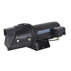
SHALLOW WELL JET PUMPS
SKU: 691-0206, 691-0208
Models: BA94506, BA94706
Safety Guidelines
Carefully read, understand and follow all safety instructions in this manual. This is the safety alert symbol. When you see this symbol, look for one of the following signal words.
DANGER: Indicates a hazardous situation which, if not avoided, will result in death or serious injury.
CAUTION: Indicates a hazardous situation which, if not avoided, could result in death or serious injury.
WARNING: Indicates a hazardous situation which, if not avoided, could result in minor or moderate injury.
Read these warnings carefully. Know the application and limitations of this pump. Failure to follow these warnings could result in serious bodily injury and/or property damage.
DANGER: This pump is not submersible. Do not submerge the motor in water or expose to water. Personal injury and/or death could result from electric shock.
DANGER: Do not use to pump flammable or explosive liquids such as gasoline, kerosene, fuel oil, etc. Personal injury and / or death could result. Do not use this pump in a flammable or explosive environment. This pump is intended to pump clear water only.
RISK OF ELECTRICAL SHOCK. This pump has not been investigated for use in swimming pool or marine areas.
DANGER: Do not touch this pump while standing in or walking on wet surfaces until all power is turned off. Do not touch an operating motor. Allow motor to cool before performing service. Failure to follow this warning could result in electric shock.
Specifications
Circuit Requirements. 15 Amp
Suction. 1-1/4" FNPT
Discharge. 1" FNPT
| Model |
HP |
Volts
Amps |
Total Suction Lift
(feet) |
Discharge Pressure - PSI
Gallons per minute |
Max Shutoff
(PSI) |
| 20 |
30 |
40 |
50 |
| BA94506 |
1/2 |
115/230
6.5 / 3.5 |
5' |
12.7 |
12.4 |
10 |
6.5 |
67 |
| 10' |
10.9 |
10.6 |
9.6 |
5.8 |
| 15' |
10.1 |
9.9 |
8.7 |
5.7 |
| 20' |
9.1 |
8.9 |
8 |
4.8 |
| 25' |
7.2 |
7.1 |
6.4 |
4.1 |
| BA94706 |
3/4 |
115/230
8.5 / 4.5 |
5' |
14 |
13.6 |
13.3 |
9 |
71 |
| 10' |
11.8 |
11.9 |
10.1 |
7 |
| 15' |
10.5 |
10.5 |
9 |
6.2 |
| 20' |
9.6 |
9.7 |
8.7 |
5.6 |
| 25' |
7.7 |
8 |
7.4 |
4.9 |
Installation
DANGER: Always disconnect the power source before attempting to install, service or perform maintenance. If the power source is out of sight, lock and tag in the off position to prevent unintended power application. Failure to do so could result in fatal electric shock. All wiring should be performed by a qualified electrician.
INSTALLING / REPLACING AN OLD PUMP
Drain and remove piping from old pump. Check the piping for rust, scale etc. Replace if necessary.
Install the new pump making sure all pipe connections are air and water tight. Use pipe joint compound or Teflon tape on all pipe connections. Make sure all piping is properly supported.
NOTE: If the suction pipe can suck air, the pump will not be able to pull water from the source.
DRIVEN WELL POINT INSTALLATION
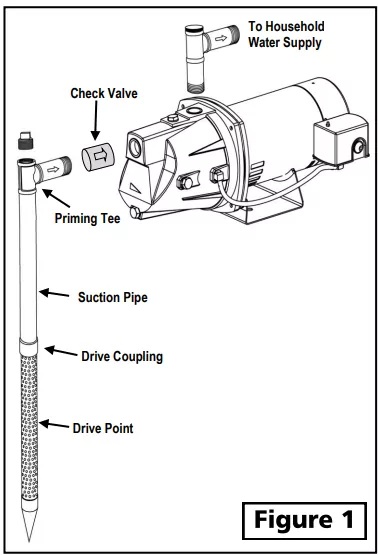
- Drive the well point using drive couplings and a drive cap. Do not use regular pipe fittings as the threads may strip out due to the force of driving the point.
- Position the pump as close as possible to the water source to keep suction lift as low as possible.
- Install a priming tee with a plug on the suction pipe from the water source. An inline check valve should also be installed on the suction line going to the pump. Install a union or other fitting that will allow the pump to be easily disassembled from the piping for easy servicing. Use Teflon tape or pipe joint compound on all joints.
- Run piping from the discharge tee on the pump housing to the household water piping.
CASED WELL POINT INSTALLATION
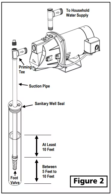
- Install a foot valve with strainer on the first section of pipe and lower it into the well.
- Add enough pipe until the foot valve is about 10 feet below the water level. Make sure the foot valve does not rest on the bottom of the well.
- Install a priming tee with a plug on the suction pipe from the water source. Install a union to allow the pump to be easily disassembled from the piping for easy servicing. Make sure Teflon tape or pipe joint compound is used on all joints. The suction pipe should be at least 1 1/4 diameter.
- Install a well seal to prevent debris and other contaminates from entering the well.
- Run piping from the discharge tee on the pump housing to the household water piping.
Electrical Connections
Use the chart below to determine what gauge wire should be used in installation
Distance in Feet from Motor to Power Supply
Wire Size (AWG) |
| 0-100' |
101-200' |
201-300' |
301-400' |
| 14 |
12 |
10 |
8 |
| 14 |
12 |
10 |
8 |
CAUTION: Risk Of Fire. Never connect a 230 volt line to a 115 volt motor.
WARNING: All wiring must be performed by a qualified electrician.
WARNING: Disconnect the power source to the pump before installing or performing service
NOTE: Check Voltage Setting Switch. The voltage switch is factory set for 115 volt service. If you have 115 volt power supply, do not change the voltage switch. The voltage switch is located under the cap on the back of the motor. Remove the two screws that secure the cap to access the switch.
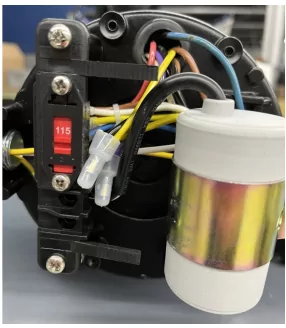
The voltage switch is factory set for 115 volt service.
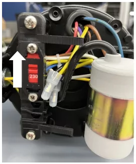
To change to 230 volt operation slide the voltage switch to "230" volts
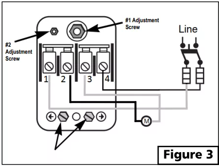
CONNECT POWER SUPPLY TO PRESSURE SWITCH
Wiring directions can be found under the pressure switch cover.
- Connect the ground wire from the power supply to the ground terminal on the pressure switch. Make sure the ground from the power source is connected to a grounded terminal in the service panel, a metal underground water pipe, a metal well casing, or a grounding rod.
- Connect the "line" from the power source to one of the screw terminals on the pressure switch.
- Connect the other "line" from the power source to the other screw terminal on the pressure switch and tighten
- To adjust pressure settings, follow directions underneath the pressure switch cover.
Troubleshooting
| PROBLEM |
POSSIBLE CAUSES |
HOW TO CORRECT |
| If the pump does not start or run |
Pump is not plugged in, switch/breaker is off |
Plug pump in or turn on switch/breaker |
| Check for blown fuses or tripped circuit breakers or tripped GFCI outlets |
Replace fuse, reset breaker, reset GFCI |
| Wire connections are loose or wired incorrectly |
Tighten connections or re-wire following wiring diagram on page 10 |
| Contacts on pressure switch are dirty or worn |
Clean or replace pressure switch |
| Motor runs hot and thermal overload protector turns pump off |
Voltage is too low |
Use heavier gauge wire |
| Motor is not properly vented |
Make sure there is adequate room for air to circulate around the pump |
| If the pump runs but moves little or no water |
|
|
| Loss of prime |
Re-prime if necessary. |
| Air lock in suction line |
Make sure horizontal piping between the pump and the well pitches upward towards the pump. Otherwise an airlock may form |
| Leak in suction line |
Check all connections for leaks. Make sure all connections are air tight. |
| Discharge or suction pipes may be clogged or corroded |
Remove clog or replace pipes if necessary |
| Distance from the pump to the water is greater than 25 feet |
Change to a deep well application |
| Intake screen/foot valve is obstructed |
Clean or replace if necessary |
| Foot valve or check valve is stuck in the closed position |
Inspect, repair or replace if necessary |
| Foot valve or check valve is installed backwards |
Make sure valve is installed in the correct direction of flow |
| Worn, damaged or clogged pump parts (Injector, impeller, diffuser, seal, etc.) |
Inspect for wear, damage or clog and clean or replace if necessary |
| Foot valve is buried in sand or mud |
Raise above surface bottom |
| Water level in the well is too low |
Lower suction pipe or convert to deep well application |
| Well is "dry" or has slow recovery |
Move location of well |
| Pipes are frozen |
Thaw pipes, heat pump house or bury pipes below frost line |
| Pump starts and stops too often |
Water logged tank (Standard Tank) |
Drain tank and re-prime pump. The air volume control will supply the correct amount of air in the tank |
| Ruptured bladder (Pre-charged Tank) |
Replace bladder and/or tank |
| Incorrect air pressure in tank (Pre-charged Tank) |
Add or release air as needed |
| Leak in pressure tank or system piping |
Locate and repair leak |
| Pressure switch is not properly adjusted |
Adjust settings by following instructions under the pressure switch cap |
| Pump does not shut off |
Incorrect pressure switch setting |
Lower "cut off" setting. Follow instructions under pressure switch cap |
| Bad pressure switch. Contacts stuck in closed position |
Replace switch |
| Pressure switch tubing clogged |
Blow debris from tubing or replace |
Replacement Parts
To order replacement parts call 1-800-495-9278
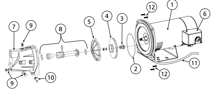
| Ref# |
Description |
BA94506 |
BA94706 |
| 1 |
Motor |
* |
* |
| 2 |
O-ring |
99226 |
99226 |
| 3 |
Mechanical Shaft Seal |
99225 |
99225 |
| 4 |
Impeller (Includes nut & washer) |
99228 |
99228 |
| 5 |
Diffuser |
99229 |
99229 |
| 6 |
Pressure Switch |
99230 |
99230 |
| 7 |
Pump Housing - Cast Iron |
99232 |
99232 |
| 8 |
Venturi assembly with O-rings |
99241 |
99241 |
| 9 |
1/4" NPT plug with washer |
99247 |
99247 |
| 10 |
1/4" NPT tubing adapter |
99249 |
99249 |
| 11 |
Tubing (.170" ID x 1/4" OD) |
Purchase Locally |
| 12 |
Mounting Bolts (M8-1.25 x 22mm) |
Purchase Locally |
*if motor fails, replace entire pump
Limited WARRANTY
Manufacturer warrants the products specified in this warranty to be free from defects in material or workmanship for three (3) years from date of purchase. During the time period and subject to the terms and conditions, the manufacturer will repair or replace to the original user or consumer any portion of this product which proves to be defective due to materials or workmanship. At all times the manufacturer shall have and possess the sole right and option to determine whether to repair or replace defective equipment, parts, or components. The manufacturer has the option to inspect any product returned under warranty to confirm that the warranty applies before repair or replacement under warranty is approved. This warranty sets forth the manufacturer's sole obligation and purchaser's exclusive remedy for defective product. Return defective product to the place of purchase for warranty consideration.
WARRANTY PERIOD-PRODUCTS:
If, within the duration of product use by the original user, this product proves to be defective due to materials or workmanship, the product shall be repaired or replaced at the manufacturer's option, subject to the terms and conditions set forth in this warranty statement. Proof of purchase is required for warranty consideration. In the absence of suitable proof of the purchase date, the effective period of this warranty is 3 years from the product's date of manufacture.
LABOR, ETC. COSTS:
The manufacturer shall IN NO EVENT be responsible or liable for the cost of field labor or other charges incurred by any customer in removing and/or affixing any product, part, or component thereof.
PRODUCT IMPROVEMENTS:
The manufacturer reserves the right to change or improve its products or any portions thereof without being obligated to provide such a change or improvement for units sold and/or shipped prior to such change or improvement.
GENERAL TERMS AND CONDITIONS:
This warranty shall not apply to damage due to acts of God, normal wear and tear, normal maintenance services and the parts used in connection with such service, lightning or conditions beyond the control of the manufacturer, nor shall it apply to products which, in the sole judgment of the manufacturer, have been subject to negligence, abuse, accident, misapplication, tampering, alteration; nor due to improper installation, operation, maintenance or storage; nor to excess of recommended maximums as set forth in the instructions. Warranty will be VOID if any of the following conditions are found:
1. Product is used for purposes other than those for which it was designed and manufactured
2. Product not installed in accordance with applicable codes, ordinances, and good trade practices
3. Product connected to voltage other than indicated on nameplate or labels
4. Pump exposed to but not limited to the following: sand, gravel, cement, grease, plaster, mud, tar, oil, gasoline, solvents or other abrasive or corrosive substances
5. Pump has been used for pumping liquids above 120°F
6. Pump allowed to operate dry (liquid supply cut off)
DISCLAIMER:
Any oral statements about the product made by the seller, the manufacturer, the representatives, or any other parties do not constitute warranties, shall not be relied upon by the user, and are not part of the contract for sale. Seller's and the manufacturers only obligation, and buyer's only remedy, shall be the replacement and/or repair by the manufacturer of the product as described above. NEITHER SELLER NOR THE MANUFACTURER SHALL BE LIABLE FOR ANY INJURY, LOSS OR DAMAGE, DIRECT, INCIDENTAL OR CONSEQUENTIAL (INCLUDING, BUT NOT LIMITED TO, INCIDENTAL OR CONSEQUENTIAL DAMAGES FOR LOST PROFITS, LOST SALES, INJURY TO PERSON OR PROPERTY, OR ANY OTHER INCIDENTAL OR CONSEQUENTIAL LOSS), ARISING OUT OF THE USE OR THE INABILITY TO USE THE PRODUCT, AND THE USER AGREES THAT NO OTHER REMEDY SHALL BE AVAILABLE TO IT. Before using, the user shall determine the suitability of the product for his/her intended use, and user assumes all risk and liability whatsoever in connection therewith.
THE WARRANTY AND REMEDY DESCRIBED IN THIS LIMITED WARRANTY IS AN EXCLUSIVE WARRANTY AND REMEDY AND IS IN LIEU OF ANY OTHER WARRANTY OR REMEDY, EXPRESSED OR IMPLIED, WHICH OTHER WARRANTIES AND REMEDIES ARE HEREBY EXPRESSLY EXCLUDED, INCLUDING BUT NOT LIMITED TO ANY IMPLIED WARRANTY OF MERCHANTABILITY OR FITNESS FOR A PARTICULAR PURPOSE, TO THE EXTENT EITHER APPLIES TO A PRODUCT SHALL BE LIMITED IN DURATION TO THE PERIODS OF THE EXPRESSED WARRANTIES GIVEN ABOVE.
Some states and countries do not allow the exclusion or limitations on how long an implied warranty lasts or the exclusion or limitation of incidental or consequential damages, so the above exclusion or limitations may not apply to you. This warranty gives you specific legal rights, and you may also have other rights which vary from state to state.