
Technical Support and E-Warranty Certificate
www.vevor.com/support
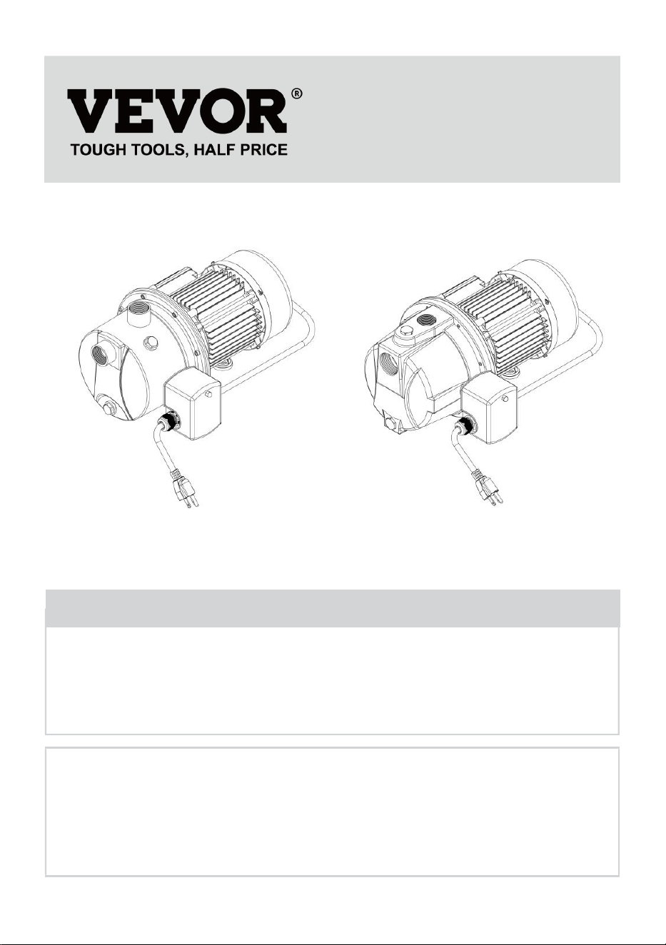
SPRINKLER PUMP
OPERATING INSTRUCTIONS
MODEL:ZX11003/ZX11004/ZX11007
We continue to be committed to provide you tools with competitive price.
"Save Half", "Half Price" or any other similar expressions used by us only represents an
estimate of savings you might benefit from buying certain tools with us compared to the major
top brands and does not necessarily mean to cover all categories of tools offered by us. You
are kindly reminded to verify carefully when you are placing an order with us if you are
actually saving half in comparison with the top major brands.
- 1 -
Have product questions? Need technical support? Please feel free to
contact us:
Technical Support and E-Warranty Certificate
www.vevor.com/support
NEED HELP? CONTACT US!
This is the original instruction, please read all manual instructions
carefully before operating. VEVOR reserves a clear interpretation of our
user manual. The appearance of the product shall be subject to the
product you received. Please forgive us that we won't inform you again if
there are any technology or software updates on our product.
SPRINKLER PUMP
MODEL:ZX11003/ZX11004
MODEL:ZX11007

- 2 -
Warning-To reduce the risk of injury, user must read
instructions manual carefully.
SAFETY WARNINGS
WARNING
Read this material before using this product. Failure to do so can result in serious
injury.
SAVE THIS MANUAL.
Before start-up, note the following:
The plug must have a supply voltage of AC115V 60 Hz.
CAUTION
This pump has been evaluated for use with water only.
WARNING
IMPORTANT! For your own safety – before starting to run the pump, please have
the following items checked by an expert:
1. Risk of electric shock – This pump is supplied with a grounding conductor and
grounding-type attachment plug. To reduce the risk of electric shock,
be certain that it is connected only to a properly grounded, grounding-type
receptacle.
2. Risk of electric shock – This pump has not been investigated for use in
swimming pool areas.
3. The electrical connections must be protected from moisture.
4. If there is danger of flooding, the electrical connections must be taken to higher
ground.
5. Circulation of caustic fluids, as well as the circulation of abrasive materials, must
be avoided at all costs.
6. The pump must be protected from frost.
7. The pump must be protected from running dry.
8. Access by children should also be prevented with appropriate measures.

- 3 -
9. To prevent death from electric shock, pump must be connected only to a
GFCI protected outlet.
10. Do not use an extension cord with this item.
11. People with pacemakers should consult their physician(s) before use.
Electromagnetic fields in close proximity to heart pacemaker could cause
pacemaker interference or pacemaker failure.
12. The warnings, precautions, and instructions discussed in this instruction
manual cannot cover all possible conditions and situations that may occur.
It must be understood by the operator that common sense and caution are factors
which cannot be built into this product, but must be supplied by the operator.
Fluid Type
The Pump is designed for use with water with a maximum temperature of 95° F
(35°C). Do not use the pump
for other fluids, especially not fuels, cleaning fluids, or other chemical products.
SPECIFICATIONS
Model
Nominal
Voltage
Rated Power
(HP)
Max Flow
(GPM)
Max lift
(FT)
Optimum
Operating
temperature
ZX11003
AC115V
60Hz
1.0
18.5
147.6
32-95° F
( 0℃-35℃ )
ZX11004
AC115V
60Hz
0.75
18.5
131
ZX11007
AC115V
60Hz
1.0
17.6
164

- 4 -
INSTALLATION
The pump must be installed in a stationary position with either:
a. A fixed pipeline or
b. A flexible hose pipe.
Please note!
1. Do not install the pump by suspending it unsupported from its delivery pipe or
power cord. The pump must be suspended from the handle or be placed on the
bottom of the basin.
To ensure that the pump works properly, keep the bottom free from sludge and dirt
of all kinds.
2. If the water level sinks too low, any sludge in the basin will dry out and stop the
pump from starting.
To help ensure the pump will start as required, check the pump regularly with
start-up tests.
Power Supply
1. The pump is equipped with a shock-proof plug according to regulations. The
pump is designed to be connected to 115 VAC, 60 Hz GFCI protected socket.
2. Make sure that the socket is sufficiently secured and is in excellent condition.
3. When the plug is inserted into the socket, the pump will be on standby.
4. WARNING: To prevent death from electric shock, pump must be
connected only to a GFCI protected outlet.
WARNING! TO PREVENT SERIOUS INJURY:
If the power cord or plug is damaged, do not use the pump. The power cord or plug
may only be repaired by a certified electrician.
Areas of use
1. This pump is designed to pump water only.
2. This pump is designed to be used for: Irrigation systems, lawn sprinkling,
and clear water transfer.
- 5 -
3. This pump should NOT be used for: Continuous run, fountain/pond water
features. Water with dirt and debris. Removing water from swimming pools or spas.
Septic or sewage systems.
4. This pump can also be used to transfer water
(e.g. household, farming, plumbing).
INSTALLATION INSTRUCTIONS
1. Position Pump on solid surface.
WARNING! TO PREVENT SERIOUS INJURY: This is NOT a submersible pump.
Do not immerse in water.
2. Plug Power Cord into GFCI protected outlet.
3.The Pump uses 3/4" NPT piping (sold separately)
Purchase the necessary length of pipe, including any needed fittings and bends.
Mount the Pump as close to the source of water as possible and within the range
of the rated Suction Lift. The connections must be airtight. Wrap all threaded
connections with PTFE tape (sold separately).
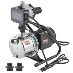
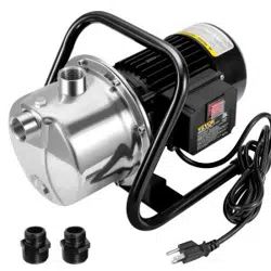
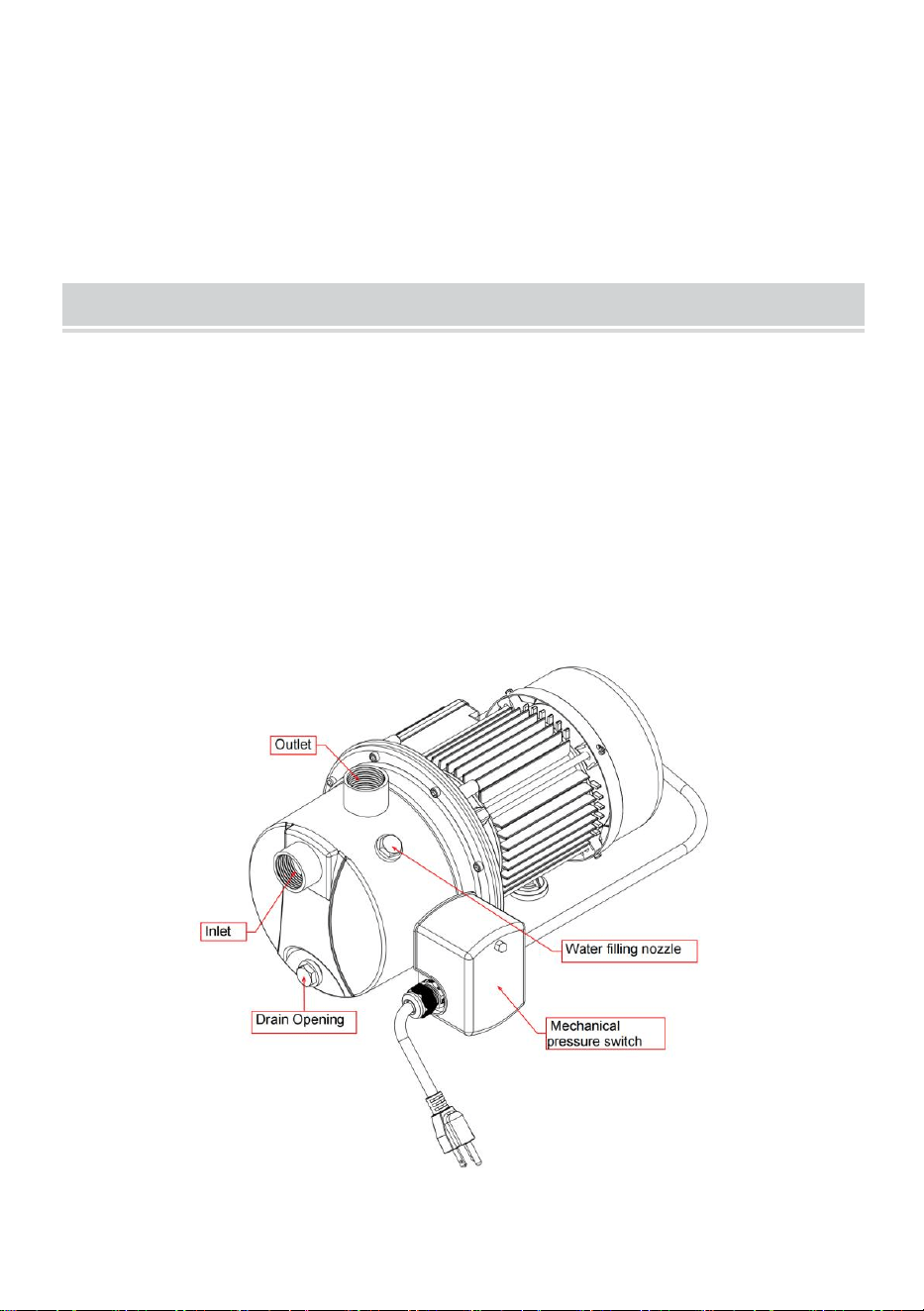
Pump Components(Model:ZX11003/ZX11004)
(Please refer to the physical object.)
- 6 -
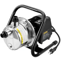
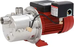
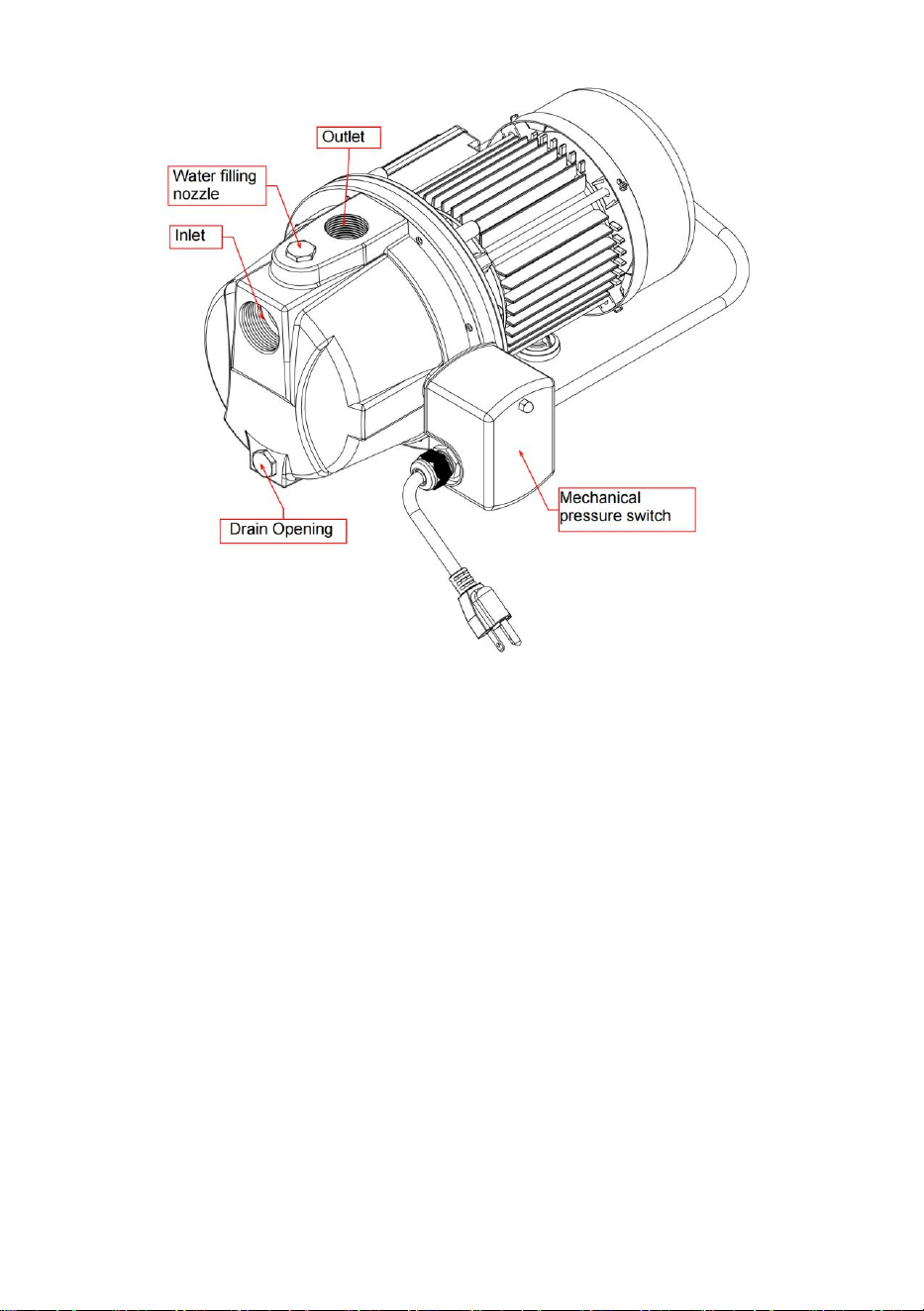
Pump Components(Model:ZX11007)
(Please refer to the physical object.)
4. Remove the Inlet and Outlet Covers from the Pump.
5. Attach the water source to the Inlet, using appropriate methods. The Inlet hose
or pipe must be collapsepro of to properly withstand the suction force.
6. Install a foot valve and filter (sold separately) at the bottom of the inlet.
- 7 -
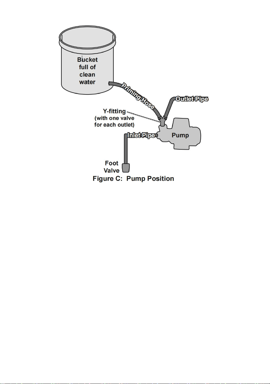
7. Attach the outlet connection to the Outlet.
A Y-fitting with dual valves (sold separately) is helpful for priming the pump (see
Figure B).
Note: A foot valve on the inlet connection is critical to help prevent the pump from
losing prime.
Note: Check that the water source and piping are clear of sand, dirt and debris.
8. Connect a bucket full of at least 3 gallons of water to one side of the Y-fitting
using a hose, as shown above. (If available, a continuous water supply, such as a
spigot, may be used instead.) The bucket must be positioned higher than the
pump’s outlet.
9. Close the valve on the outlet side of the Y-fitting, and open the valve on the
priming side of the Y-fitting.
10. Remove the Priming Plug and wait until water starts coming out of the Priming
Plug. Replace the Priming Plug and tighten securely.

- 8 -
OPERATION
After reading these instructions, consider the following points before
starting the pump:
1. Verify that the discharge pipe is properly connected.
2. Verify that the electrical connection is AC115V, 60 Hz.
3. Verify that the electrical socket is GFCI protected and in good condition. Test
GFCI protected outlet before use.
4. Verify that water and moisture cannot get near the power supply socket.
5. Verify that the pump is installed so as to prevent running dry.
6. To start the pump:
a. Open the valve on outlet side of the Y-fitting.
b. Make sure your hands are dry.
c. Plug in the pump.
d. Turn on the Power Switch (I).
e. Close the valve on the priming side of the Y-fitting.
NOTICE: Do not run the Pump Dry!
Turn off the Pump IMMEDIATELY if water
stops coming out the Outlet.
7. If you operate the Pump and no water comes
out, shut the Pump off IMMEDIATELY. Check the
pipes for air-tightness. Check also that the bottom
of the Inlet pipe is underneath the surface of the
water and a foot valve is properly installed.
8. After the pump is running properly, the priming
hose and bucket can be disconnected.
9. When finished using the pump, turn the Power
Switch off (O), then unplug the Power Cord. Follow
procedures for Storage explained on the next page.

- 9 -
MAINTENANCE
WARNING
TO PREVENT SERIOUS INJURY FROM ACCIDENTAL OPERATION:
Unplug the Pump from its electrical outlet before performing any inspection,
maintenance, or cleaning procedures.
If the pump is moved during operation, flush it out with clean water after every use.
QUARTERLY MAINTENANCE
The below maintenance must be performed at least once every 3 months under
optimal conditions.
For frequent use, or dirty areas, more frequent maintenance is required.
1. Clean sludge and debris from the bottom of the basin.
2. Clean sludge/debris from inlet screen.
3. Make sure discharge pipe is free from leaks.
4. Make sure check valve is functioning properly.
5. Manually operate flow switch to determine that pump turns on/off as intended.
LONG TERM STORAGE
1. Drain Pump Body. Disconnect both suction and outlet lines, then tip pump so
that all water is drained from pump cavity.
2. If the Pump sits idle for a period of 5 days or more, it should be unplugged and
rotated with a screwdriver through the middle hole of the fan cover through several
revolutions to prevent it from taking a permanent set.
3. If you use the Pump only occasionally, when you are done pumping, replace the
Inlet and Outlet covers to protect the unit.

- 10 -
TROUBLESHOOTING
PROBLEM
POSSIBLE CAUSES
POSSIBLE SOLUTIONS
Pump runs, but
will not deliver
any water.
1. When starting, the water
height falls below the
minimum water level (0")
2. Low line voltage.
3. Check valve (sold
separately)
stuck or installed backwards.
4. Improper priming.
5. Clogged filter at end of
intake connections.
6. Discharge valve closed.
7. Pipe size too small.
8. Impeller plugged.
9. Pipes frozen.
1. There must be at least 0"
deep water for the Pump to
operate properly.
2. Consult an electrician.
3. Remove and examine
check valve.
4. Re-prime according to
directions.
5. Clean filter.
6. Open discharge valve.
7. Re-pipe using pipe of the
same size as the Pump inlet
and outlet ports.
8. Have Impeller cleaned by
qualified service technician.
9. Thaw pipes. Check for
damage before using pump.
Pump won’t
start or run.
1. Check power connections
and circuits/fuses.
2. Water level too low.
3. Defective motor.
4. Cord not connected.
5. No power at outlet.
6. Fuse is blown or breaker
tripped.
1. Consult an electrician.
2. Allow water level to rise
above 0"or move Pump to a
lower location.
3. Have a qualified service
technician repair or replace.
4. Check that cord is plugged
in.
5. Check power at outlet. If
outlet is unpowered,
turn off tool and check circuit
breaker. If breaker is tripped,

- 11 -
make sure circuit is right
capacity for tool and circuit
has no other loads.
6. Have fuse replaced by a
qualified service technician.
7. Have serviced by a
qualified service technician.
Pump does not
deliver water at
full capacity.
1. Corroded pipes.
2. Piping size too small.
3. Not enough water supplied
to Pump.
4. Low Voltage.
1. Replace pipes.
2. Re-pipe using pipe of the
same size as
the Pump inlet and outlet
ports.
3. Enlarge inlet pipe. Check
well pump system.
4. Check that outlet is 115V.
Excessive noise
or vibration.
Internal damage or wear.
(Carbon brushes or bearings,
for example.)
Have technician service tool.
Pump starts
and stops too
frequently.
1. Water temperature too
high.
2. Check valve (sold
separately)
stuck or installed backwards.
3. Back flow of water from
discharge hose.
1. Do not exceed 77° F
(25°C) water temperature.
2. Remove and examine
check valve.
3. Install or inspect check
valve (sold separately).
Follow all safety precautions whenever diagnosing or servicing the
tool.
Disconnect power supply before service.

- 12 -
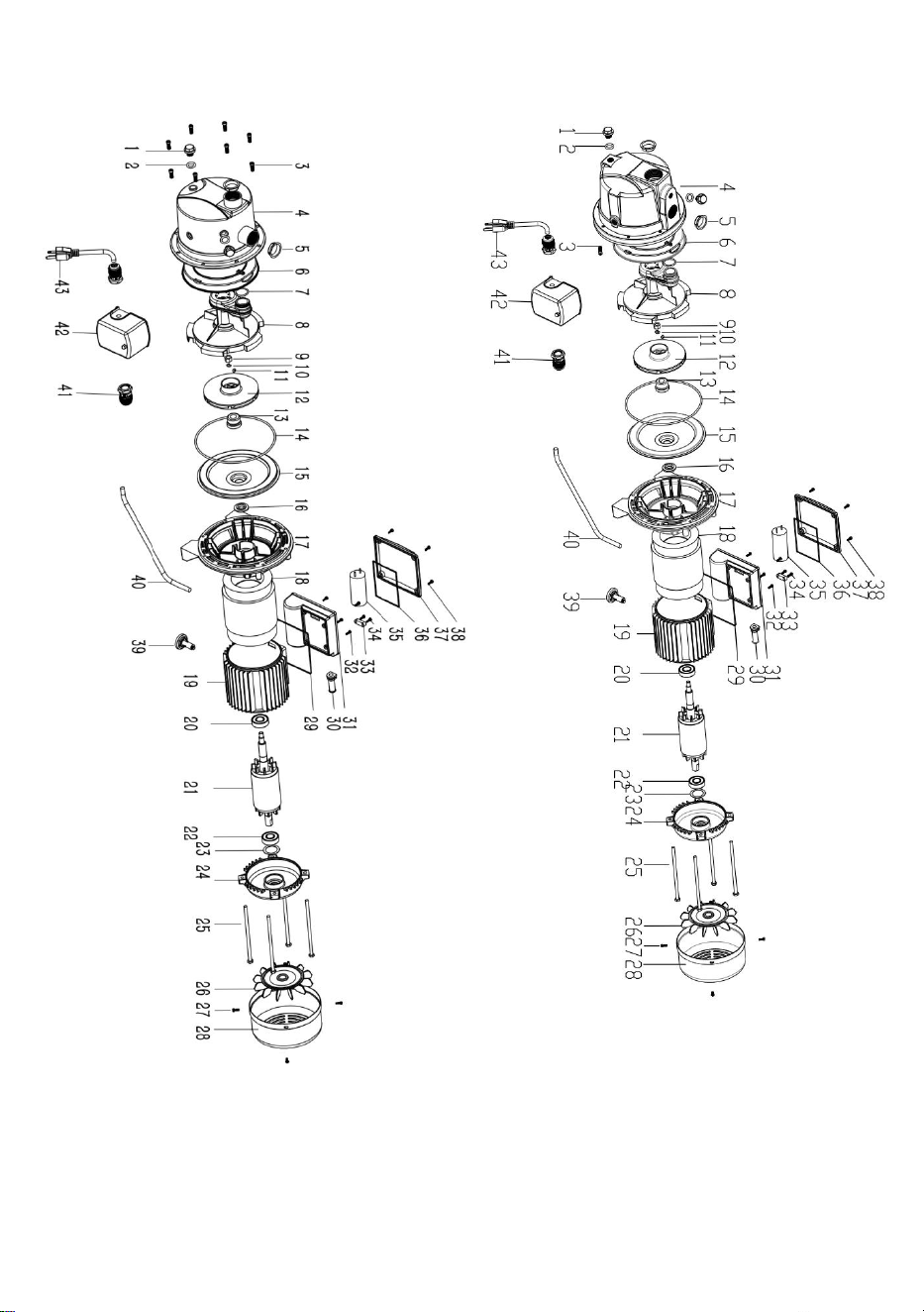
PARTS LIST AND DIAGRAM
PLEASE READ THE FOLLOWING CAREFULLY
THE MANUFACTURER AND/OR DISTRIBUTOR HAS PROVIDED THE PARTS
LIST AND ASSEMBLY DIAGRAM
IN THIS MANUAL AS A REFERENCE TOOL ONLY. NEITHER THE
MANUFACTURER OR DISTRIBUTOR
MAKES ANY REPRESENTATION OR WARRANTY OF ANY KIND TO THE
BUYER THAT HE OR SHE IS
QUALIFIED TO MAKE ANY REPAIRS TO THE PRODUCT, OR THAT HE OR
SHE IS QUALIFIED TO REPLACE
ANY PARTS OF THE PRODUCT. IN FACT, THE MANUFACTURER AND/OR
DISTRIBUTOR EXPRESSLY
STATES THAT ALL REPAIRS AND PARTS REPLACEMENTS SHOULD BE
UNDERTAKEN BY CERTIFIED AND
LICENSED TECHNICIANS, AND NOT BY THE BUYER. THE BUYER ASSUMES
ALL RISK AND LIABILITY
ARISING OUT OF HIS OR HER REPAIRS TO THE ORIGINAL PRODUCT OR
REPLACEMENT PARTS
THERETO, OR ARISING OUT OF HIS OR HER INSTALLATION OF
REPLACEMENT PARTS THERETO.
- 13 -
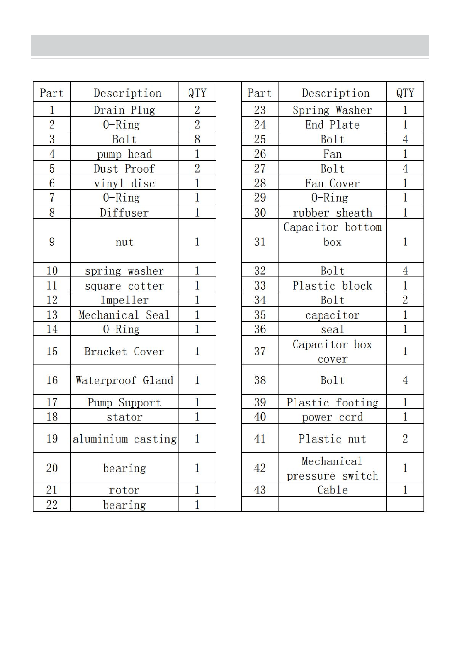
PARTS LIST
MODEL:ZX11003/ZX11004/ZX11007
Note: Some parts are listed and shown for illustration purposes only, and are not
available individually as replacement parts.
- 14 -
MODEL:ZX11003/ZX11004
MODEL:ZX11007
Made In China