Loading ...
Loading ...
Loading ...
6
© 2021 United States Stove Company
INSTALLATION
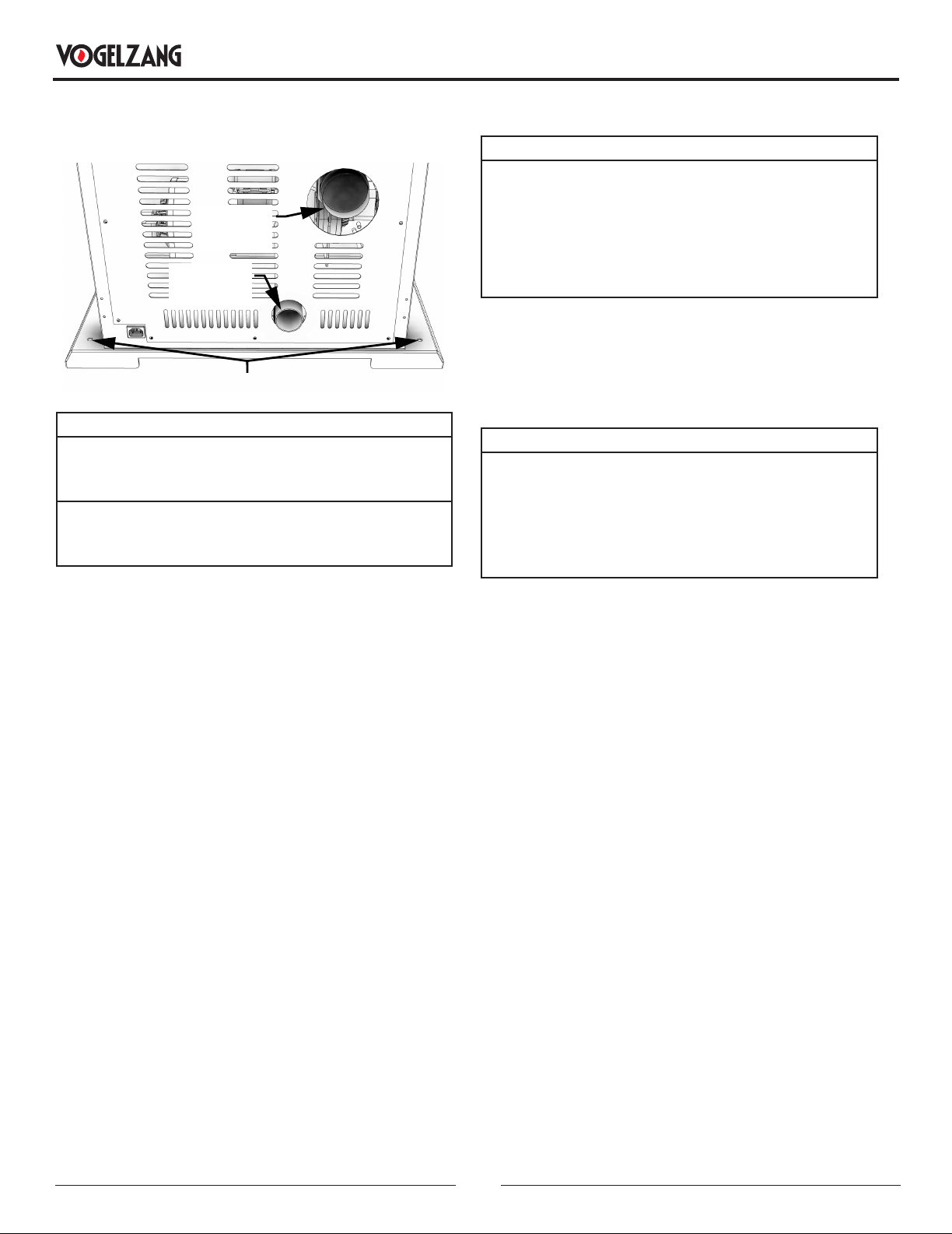
SECURING APPLIANCE TO THE FLOOR
Use the designated holes to secure the unit to the oor.
MOBILE HOME MOUNTING BOLT HOLES
Exhaust
Pipe
Fresh air
intake
WARNING! DO NOT INSTALL IN SLEEPING ROOM.
CAUTION! THE STRUCTURAL INTEGRITY OF THE
MOBILE HOME FLOOR, WALL, AND CEILING/ROOF
MUST BE MAINTAINED.
WHEN INSTALLED IN A MOBILE HOME, THE STOVE
MUST BE GROUNDED DIRECTLY TO THE STEEL
CHASSIS AND BOLTED TO THE FLOOR.
In addition to the previously detailed installation
requirements, mobile home installations must meet the
following requirements:
• This stove must be securely fastened to the oor of the
mobile home through the two holes in the rear of the
stove using two, 1/4” lag bolts that are long enough to
go through both a hearth pad, if used, and the oor of
the home.
• The heater must be electrically grounded to the steel
chassis of the mobile home with 8 GA copper wire using
a serrated or star washer to penetrate paint or protective
coating to ensure grounding.
• Vent must be 3 or 4-inch “PL” Vent and must extend a
minimum or 36” (914 mm) above the roof line of the
mobile home and must be installed using a certied
ceiling re stop and rain cap.
• When moving your mobile home, all exterior venting must
be removed while the mobile home is being relocated.
After relocation, all venting must be reinstalled and
securely fastened.
• Outside air is mandatory for mobile home installation.
See Outside Air Supply section and your dealer for
purchasing.
• Check with your local building ocials as other codes
may apply.
VENTING REQUIREMENTS
WARNING:
• INSTALL VENT AT CLEARANCES SPECIFIED BY THE
VENT MANUFACTURER.
• DO NOT CONNECT THE PELLET VENT TO A VENT
SERVING ANY OTHER APPLIANCE OR STOVE.
• DO NOT INSTALL A FLUE DAMPER IN THE EXHAUST
VENTING SYSTEM OF THIS UNIT.
The following installation guidelines must be followed
to ensure conformity with both the safety listing of this
stove and to local building codes. Do not use makeshift
methods or compromise in the installation.
IMPORTANT:
THIS UNIT IS EQUIPPED WITH A NEGATIVE DRAFT
SYSTEM THAT PULLS AIR THROUGH THE BURN POT
AND PUSHES THE EXHAUST OUT OF THE DWELLING.
IF THIS UNIT IS CONNECTED TO A FLUE SYSTEM
OTHER THAN THE WAY EXPLAINED IN THIS MANUAL,
IT WILL NOT FUNCTION PROPERLY.
MAXIMUM VENTING DISTANCE
Installation MUST include at least 3-feet of vertical pipe
outside the home. This will create some natural draft to
reduce the possibility of smoke or odor during appliance
shutdown and keep exhaust from causing a nuisance or
hazard by exposing people or shrubs to high temperatures.
The maximum recommend vertical venting height is 12-
feet for 3-inch type “PL” vent. Total length of horizontal vent
must not exceed 4-feet. This could cause back pressure.
Use no more than 180 degrees of elbows (two 90-degree
elbows, or two 45-degree and one 90-degree elbow, etc.)
to maintain adequate draft.
IMPORTANCE OF PROPER DRAFT
Draft is the force which moves air from the appliance up
through the chimney. The amount of draft in your chimney
depends on the length of the chimney, local geography,
nearby obstructions and other factors. Too much draft
may cause excessive temperatures in the appliance.
Inadequate draft may cause backpung into the room and
‘plugging’ of the chimney. Inadequate draft will cause the
appliance to leak smoke into the room through appliance
and chimney connector joints. An uncontrollable burn or
excessive temperature indicates excessive draft. Take into
account the chimney’s location to ensure it is not too close
to neighbors or in a valley which may cause unhealthy or
nuisance conditions.
Loading ...
Loading ...
Loading ...