Loading ...
Loading ...
Loading ...
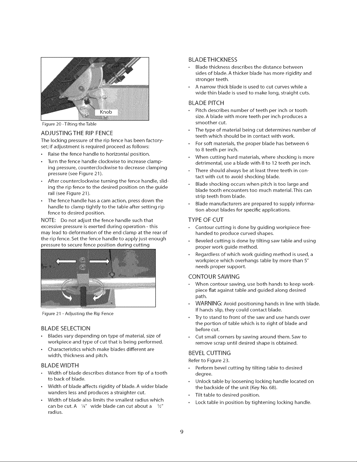
Figure 20 -Tilting theTable
Knob
ADJUSTINGTHE RIP FENCE
The locking pressure of the rip fence has been factory-
set; if adjustment is required proceed as follows:
Raise the fence handle to horizontal position.
Turn the fence handle clockwise to increase clamp-
ing pressure, counterclockwise to decrease clamping
pressure (see Figure 21 ).
After counterclockwise turning the fence handle, slid-
ing the rip fence to the desired position on the guide
rail (see Figure 21).
The fence handle has a cam action, press down the
handle to clamp tightly to the table after setting rip
fence to desired position.
NOTE: Do not adjust the fence handle such that
excessive pressure is exerted during operation - this
may lead to deformation of the end clamp at the rear of
the rip fence. Set the fence handle to apply just enough
pressure to secure fence position during cutting
Figure 21 - Adjusting the Rip Fence
BLADE SELECTION
Blades vary depending on type of material, size of
workpiece and type of cut that is being performed.
Characteristics which make blades different are
width, thickness and pitch.
BLADE WIDTH
Width of blade describes distance from tip of a tooth
to back of blade.
Width of blade affects rigidity of blade. A wider blade
wanders less and produces a straighter cut.
Width of blade also limits the smallest radius which
can be cut. A 1/4" wide blade can cut about a 1A"
radius.
BLADETHICKNESS
Blade thickness describes the distance between
sides of blade. A thicker blade has more rigidity and
stronger teeth.
A narrow thick blade is used to cut curves while a
wide thin blade is used to make long, straight cuts.
BLADE PITCH
Pitch describes number of teeth per inch or tooth
size. A blade with more teeth per inch produces a
smoother cut.
The type of material being cut determines number of
teeth which should be in contact with work.
For soft materials, the proper blade has between 6
to 8 teeth per inch.
When cutting hard materials, where shocking is more
detrimental, use a blade with 8 to 12 teeth per inch.
There should always be at least three teeth in con-
tact with cut to avoid shocking blade.
Blade shocking occurs when pitch is too large and
blade tooth encounters too much material.This can
strip teeth from blade.
Blade manufacturers are prepared to supply informa-
tion about blades for specific applications.
TYPE OF CUT
Contour cutting is done by guiding workpiece free-
handed to produce curved shapes.
Beveled cutting is done by tilting saw table and using
proper work guide method.
Regardless of which work guiding method is used, a
workpiece which overhangs table by more than 5"
needs proper support.
CONTOUR SAWING
When contour sawing, use both hands to keep work-
piece fiat against table and guided along desired
path.
WARNING: Avoid positioning hands in line with blade.
If hands slip, they could contact blade.
Try to stand to front of the saw and use hands over
the portion of table which is to right of blade and
before cut.
Cut small corners by sawing around them. Saw to
remove scrap until desired shape is obtained.
BEVEL CUTTING
Refer to Figure 23.
Perform bevel cutting by tilting table to desired
degree.
Unlock table by loosening locking handle located on
the backside of the unit (Key No. 68).
Tilt table to desired position.
Lock table in position by tightening locking handle.
Loading ...
Loading ...
Loading ...