Loading ...
Loading ...
Loading ...
TRACKINGTHE SAW BLADE
Set the tracking of the saw blade before setting the
blade guides.
Once the saw blade is installed and tensioned, track the
saw blade by adjusting the tracking knob by hand (see
Figure 16).The saw blade should run in the center of
the band saw wheels.When the correct adjustment is
achieved lock the tracking knob with the locking knob.
Tracking Knob
Figure 16 - SetTracking of Saw Blade
SETTINGTHE CUTI-ING HEIGHT
The upper blade guide should be set as close as
practical against the workpiece.
To adjust this height, loosen the locking knob at the
side of the upper wheel housing (see Figure 17).
Guide Post
Knob
Locking Knob
Figure 17 - Setting Cutting Depth
Set the blade guide to the required height by turning
the guide post adjusting knob.
Tighten locking knob after setting.
ADJUSTINGTHE BLADE GUIDES
UPPER BLADE GUIDE
See Figure 18.
To adjust the upper blade guides, first position the
right and left roller guides relative to the blade by
slackening the ratchet handle (Figure18) and moving
the guide carrier until both roller guides are approxi-
mately 1A6" behind the gullets of the saw blade.
Set both roller guides to within ]/32" of the saw blade
by releasing the guide adjusting screw (A) on each
side of the saw blade. Do not set the roller guides
too close as this will adversely affect the life of the
saw blade.
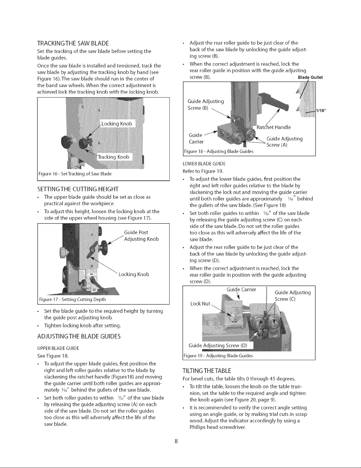
Adjust the rear roller guide to be just clear of the
back of the saw blade by unlocking the guide adjust-
ing screw (B).
When the correct adjustment is reached, lock the
rear roller guide in position with the guide adjusting
screw (B). Blade Gullet
Guide Adjusting
Screw (B)
her Handle
Guide
Guide Adjusting
Carrier (A)
Figure 18 - Adjusting Blade Guides
LOWERBLADE GUIDE
Refer to Figure 19.
To adjust the lower blade guides, first position the
right and left roller guides relative to the blade by
slackening the lock nut and moving the guide carrier
tJ
until both roller guides are approximately _A6 behind
the gullets of the saw blade. (See Figure 18)
Set both roller guides to within ]/32" of the saw blade
by releasing the guide adjusting screw (C) on each
side of the saw blade. Do not set the roller guides
too close as this will adversely affect the life of the
saw blade.
Adjust the rear roller guide to be just clear of the
back of the saw blade by unlocking the guide adjust-
ing screw (D).
When the correct adjustment is reached, lock the
rear roller guide in position with the guide adjusting
screw (D).
Guide Carrier
Guide Adjusting
Screw (C)
1/16"
Guide Adjusting Screw (D)
Figure 19- Adjusting Blade Guides
TILTING THETABLE
For bevel cuts, the table tilts 0 through 45 degrees.
To tilt the table, loosen the knob on the table trun-
nion, set the table to the required angle and tighten
the knob again (see Figure 20, page 9).
It is recommended to verify the correct angle setting
using an angle guide, or by making trial cuts in scrap
wood. Adjust the indicator accordingly by using a
Phillips head screwdriver.
Loading ...
Loading ...
Loading ...