Loading ...
Loading ...
Loading ...
Locate four hex bolts and four lock washers from the
bag of loose parts. Mount the table to the upper table
trunnion and install a bolt with washer in each hole, and
then tighten with adjustable wrench.
CENTERINGTHE TABLE
Loosen the four hex bolts mounting the table to the
upper table trunnion (see Figure 3).
Hex Bolt
Figure 3 - Hex Bolts forTrunnion
Move the table sideways as required, until the saw
blade runs through the center of the table insert.
If moving the upper table trunnion is not enough to
center the table, loosen the four flange nuts holding
the lower table trunnion and move the table side-
ways to place the table in the center.
Re-tighten hex bolts for trunnion and flange nuts,
recheck the saw blade position.
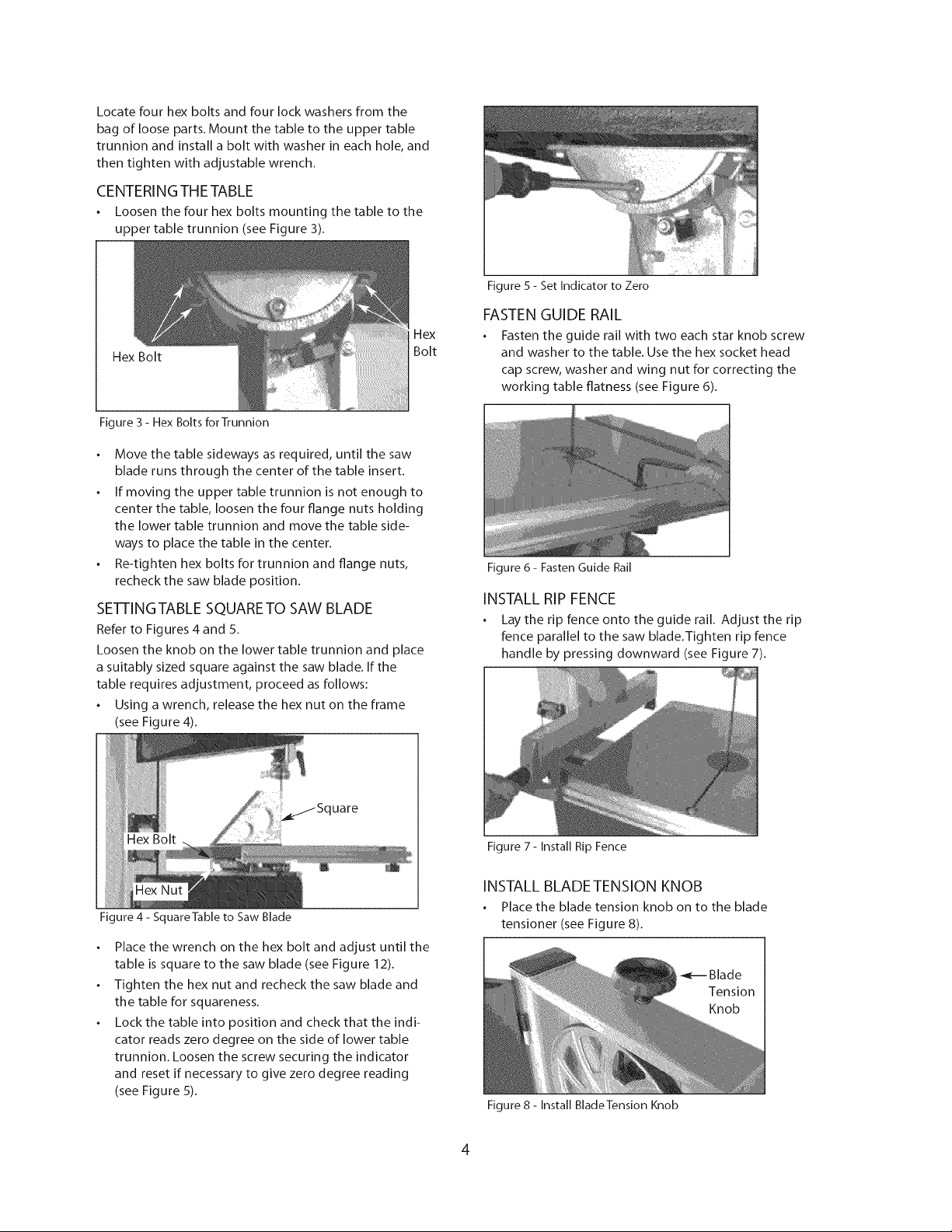
SE'FFINGTABLE SQUARETO SAW BLADE
Refer to Figures 4 and 5.
Loosen the knob on the lower table trunnion and place
a suitably sized square against the saw blade. If the
table requires adjustment, proceed as follows:
Using a wrench, release the hex nut on the frame
(see Figure 4).
ii
..... uare
===
Hex Bolt
Figure 4 - SquareTable to Saw Blade
Place the wrench on the hex bolt and adjust until the
table is square to the saw blade (see Figure 12).
Tighten the hex nut and recheck the saw blade and
the table for squareness.
Lock the table into position and check that the indi-
cator reads zero degree on the side of lower table
trunnion. Loosen the screw securing the indicator
and reset if necessary to give zero degree reading
(see Figure 5).
aex
Bolt
Figure 5 - Set Indicator to Zero
FASTENGUIDE RAIL
Fasten the guide rail with two each star knob screw
and washer to the table. Use the hex socket head
cap screw, washer and wing nut for correcting the
working table flatness (see Figure 6).
Figure 6 - Fasten Guide Rail
INSTALL RIP FENCE
Lay the rip fence onto the guide rail. Adjust the rip
fence parallel to the saw blade.Tighten rip fence
handle by pressing downward (see Figure 7).
Figure 7 - Install Rip Fence
INSTALL BLADETENSION KNOB
Place the blade tension knob on to the blade
tensioner (see Figure 8).
Figure 8 - Install BladeTension Knob
Blade
Tension
Knob
4
Loading ...
Loading ...
Loading ...