
* The packing contents may be different based on the kit you purchased. Please take the actual
product as standard.
Vision S Camera System
User Manual
Models:
FOS07TASR / FOS07TASF / FOS07TAED / FOS07TAPT / FOS05TASR / FOS05TASF
FOS05TAED / FOS05TAPT / FOS43TASR / FOS43TASF / FCN48TASK / FCN48TASF
FCE48TASL / FCE48TASH / FOS43TDDC / FOS05TAEN / FSO07TAEN / FOS05TAEM
FOS07TAEM / FOS05TASM / FOS07TASM / FOS43TASM / FOS07TAPM

2
Welcome
Thank you for purchasing the Furrion® Vision S Camera System. Before operating your new
product, please read these instructions carefully. This will ensure safe use and reduce the risk of
injury. This instruction manual contains information for installation, maintenance of the product
and safe use.
Please keep this instruction manual in a safe place for future reference. Be sure to pass on this
manual to any new owners of this product.
The manufacturer does not accept responsibility for any damages due to not observing these
instructions.
If you have any questions regarding our products, please contact us at: [email protected]

3
Contents
Welcome......................................................................................................................... 2
Contents......................................................................................................................... 3
Important Safety Instructions..................................................................................... 4
FCC Statement..........................................................................................................................................................5
IC Statement.............................................................................................................................................................. 6
Care and Cleaning....................................................................................................................................................7
Maintenance .................................................................................................................. 7
Product Overview ......................................................................................................... 8
Install and Use Monitor................................................................................................12
Install and Use 4.3” Monitor................................................................................................................................12
Install and Use 5”/7” Monitor .............................................................................................................................18
Install Cameras............................................................................................................28
Install Doorway Security/Rear Camera ......................................................................................................28
Install Side Cameras & Rear Camera withMarker Light.......................................................................31
Troubleshooting..........................................................................................................34

4
Important Safety Instructions
Generic safety instructions
READ THESE INSTRUCTIONS
CAREFULLY BEFORE INSTALLING OR
USING THE SYSTEM
When used as an observation system, this
product is intended to assist in safe driving
and to allow the driver to have a broader view.
Do not back up your vehicle while watching
the monitor screen. Always look in the
direction the vehicle is traveling.
Use the monitor as an aid to ensure there are
no children or obstructions. The image on
the monitor is not designed to show distance
and may be misleading. The actual distance
is less than what appears in the monitor. The
range of the image is limited. Be aware of
blind spots.
You, as the driver, are solely responsible for
the safe operation of your vehicle and the
safety of your passengers according to your
local traffic regulations.
Do not use any features of this system to the
extent it distracts you from safe driving.
Your first priority while driving should
always be the safe operation of your vehicle.
Furrion cannot accept any responsibility for
accidents resulting from failure to observe
these precautions or safety instructions.
1. This product utilizes high voltage. Any
unauthorized modifications or damage to
the product may result in electrical shock.
Handle all components with care. Inspect
regularly for damage to components and
cabling.
2. You are responsible for ensuring the
installation of this product does not void
or affect the vehicle manufacturer’s
warranty. Furrion is not liable in full or in
part for improper installation resulting
in loss or damage to your property,
or for voiding all or part of the vehicle
manufacturer’s warranty.
3. Do not apply excessive force to any of
the components contained within this
kit. Excessive force used before, during
or after installation that results in a
damaged or nonfunctional part will void all
warranties.
4. Please follow the procedures in this
instruction manual. Improper installation
or modification of this product will void all
warranties.
Many jurisdictions have laws and regulations
relating to the use of cameras and some do
not allow for the obstruction of information
contained on a license plate. Before using this
product, it is the buyer’s responsibility to be
aware of and comply with any applicable laws
and regulations that apply to license plates or
may prohibit or limit the use of cameras.
Electrical Safety
● Ensure all power sources are isolated
before installation.
● Insulate unconnected wires with vinyl
tape or similar.
● Use insulated tools when working with a
power supply.
● For EU countries:
− The Vision S product shall be powered by
12V or 24V external power supply, with
a properly sized fuse or breaker (5A for
12V or 3A for 24V) mounted between the
product and power supply.
− The external power supply used with
this product shall comply with the LPS
(Limited Power Source) requirements or
shall be a Power Source Class 2 (PS2)
with less than 100W.
Caution
● There are no serviceable parts in the
Furrion
®
Vision S Camera System. Do not
disassemble or attempt any repairs.
● Install external fuses/breakers as
required.

5
Important Safety Instructions
Installation
● Installation and wiring of this product
require specialist skills. To ensure proper
and safe installation, please seek a
specialist technician.
● Only use supplied or recommended parts.
● Use watertight connectors for the camera
power supply cable to power source.
● Connect the camera to a 12-24V DC
circuit using 18AWG or larger cables.
● Ensure correct polarity of DC power
supply to the camera.
● To reduce the risk of fire, connect the
camera only to a circuit provided with
a maximum branch-circuit over current
protection device.
● Do not route wiring in areas that may get
hot.
● Take necessary precautions when working
at elevated levels.
Use
● Electrical appliances and overhead power
lines can affect the wireless signal.
● Do not place the monitor in a location
where it might hinder field of vision while
driving.
● Consideration should be given to any
airbags when installing the monitor. Do
not place the monitor where it might
hinder the airbag or become hazardous if
the airbag is deployed.
Care
● Do not wash the vehicle with an automatic
car wash or high pressure water. This may
damage the camera.
● Clean the LCD screen with a microfiber
cloth. Do not use coarse or abrasive
materials.
● Do not use alcohol or ammonia based
products to clean the LCD screen. Only
use specialist screen cleaning products.
● Use a wet cloth to clean the camera lens.
A dry cloth may scratch the camera lens.
FCC Statement
The equipment complies with RF exposure
limits. This module is limited to installation
in mobile or fixed applications. The antenna
used for this transmitter must not be co-
located or operating in conjunction with any
other antenna or transmitter.
This device complies with Part 15 of the
FCCRules. Operation is subject to the
following two conditions:
(1) This device may not cause harmful
interference.
(2) This device must accept any interference
received, including interference that may
cause undesired operation.
NOTE: The Grantee is not responsible for
any changes or modifications not expressly
approved by the party responsible for
compliance. Such modifications could void
the user’s authority to operate the equipment.
NOTE: This equipment has been tested
and found to comply with the limits for a
Class B digital device, pursuant to part
15 of the FCCRules. These limits are
designed to provide reasonable protection
against harmful interference in a residential
installation. This equipment generates, uses
and can radiate radio frequency energy
and, ifnot installed and used in accordance
with the instructions, may cause harmful
interference to radio communications.
However, there is no guarantee that
interference will not occur in a particular
installation. If this equipment does cause
harmful interference to radio or television
reception, which can be determined by
turning the equipment off and on, the user is
encouraged to try to correct the interference
by one or more of the following measures:

6
Important Safety Instructions
− Reorient or relocate the receiving
antenna.
− Increase the separation between the
equipment and receiver.
− Connect the equipment into an outlet on
a circuit different from that to which the
receiver is connected.
− Consult the dealer or an experienced
radio/TV technician for help.
RF Exposure
The device has been evaluated to meet
general RF exposure requirement.
To maintain compliance with FCC’s RF
exposure guidelines, this equipment should
be installed and operated with a minimum
distance of 20cm between the radiator and
your body.
IC Statement
This device complies with Industry Canada
licence-exempt RSS standard(s). Operation
is subject to the following two conditions:
(1)this device may not cause interference,
and (2)this device must accept any
interference, including interference that may
cause undesired operation of the device.
RF Exposure
The device has been evaluated to meet
general RF exposure requirement. To
maintain compliance with RSS-102 — Radio
Frequency (RF) Exposure guidelines, this
equipment should be installed and operated
with a minimum distance of 20cm between
the radiator and your body.

7
Maintenance
Care and Cleaning
Though your monitor requires little care, you will still need to maintain its condition and
performance by following the guidelines below.
● Keep the unit away from excessive moisture, or extreme heat or cold.
● Keep liquids away from the monitor.
● Occasionally clean the surface of the monitor with a soft cloth moistened with water or glass
cleaner.
Only clean the monitor with dry cloth. Do not clean it with strong chemical agents or abrasive
cleaners. Never spill liquid of any kind on the product. Do not allow residue or liquids to enter
any part of the monitor as this may cause risk of electrocution. Always disconnect power before
cleaning.
CAUTION: Never use solvents such as benzene, thinner or cleaners available commercially to
clean the monitor.
8
Product Overview
Furrion offers you abundant options to set up an observation / security system for your vehicle.
You can mount Furrion Vision S products onto various types of RVs such as trailers and Class
A/B/C motorhomes.
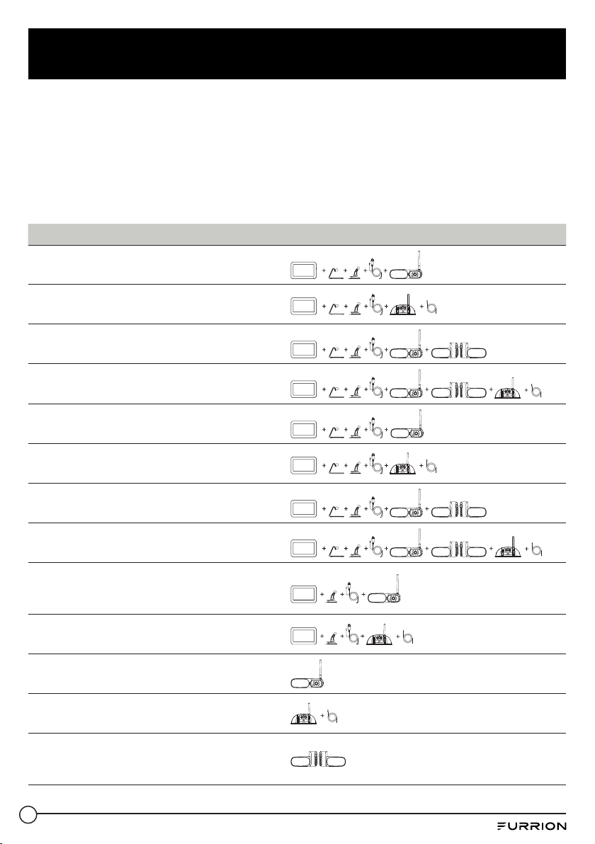
The full range of Vision S wireless monitor and camera products available for your selection
is listed below, which are sold either separately or as part of a system. Check all items in your
package against the ‘What’s in the box’ section on the packaging box to ensure you have got
all the items. You can click an icon below to jump to the corresponding section for detailed
description.
Part Number Description Product
FOS07TASR
Vision S 7” Single Camera
System with Marker Light
7”
FOS07TASF
Vision S 7” Single Camera
System
7”
FOS07TAED
Vision S 7” 3-Camera
System with Marker Lights
7”
FOS07TAPT
Vision S 7” 4-Camera
System with Marker Lights
7”
FOS05TASR
Vision S 5” Single Camera
System with Marker Light
5”
FOS05TASF
Vision S 5” Single Camera
System
5”
FOS05TAED
Vision S 5” 3-Camera
System with Marker Lights
5”
FOS05TAPT
Vision S 5” 4-Camera
System with Marker Lights
5”
FOS43TASR
Vision S 4.3” Single
Camera System with
Marker Light
4.3”
FOS43TASF
Vision S 4.3” Single
Camera System
4.3”
FCN48TASK Vision S Rear Camera
FCN48TASF
Vision S Doorway Security
or Rear Camera
FCE48TASL
Vision S Side Cameras with
Marker Lights for 5” or 7”
Display
9
Product Overview
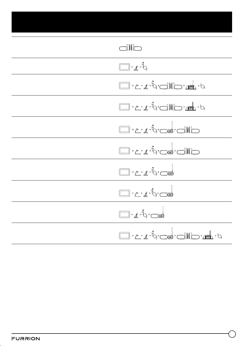
FCE48TASH
Vision S Side Cameras with
LED Marker Lights for 5” or
7” Display
FOS43TDDC Vision S 4.3” Display
4.3”
FOS05TAEN
Vision S 5” 3-Camera
System with Side LED
Marker Lights
5”
FSO07TAEN
Vision S 7” 3-Camera
System with Side LED
Marker Lights
7”
FOS05TAEM
Vision S 5” 3-Camera
System with Side and Rear
LED Marker Lights
5”
FOS07TAEM
Vision S 7” 3-Camera
System with Side and Rear
LED Marker Lights
7”
FOS05TASM
Vision S 5” Single Camera
System with LED Marker
Light
5”
FOS07TASM
Vision S 7” Single Camera
System with LED Marker
Light
7”
FOS43TASM
Vision S 4.3” Single
Camera System with LED
Marker Light
4.3”
FOS07TAPM
Vision S 7” 4-Camera
System with LED Marker
Lights
7”
10
Product Overview
Note: Product specifications are subject to change without prior notice.
Vision S Family Monitor Specification
4.3" Monitor 5" Monitor 7" Monitor
Operating Voltage
8 – 30Vdc
Wireless Frequency
2.4G
Rx Sensitivity
-88dBm+/-3dBm
Aspect Radio
16:9
Resolution
480x272 800x480 800x480
Max View on Screen
1 4 4
View Angle
L/R65,U50,D60 L/R80,U60,D70
Brightness
Min. 200cd/m² Min. 300cd/m² Min. 180cd/m²
Contract
350:1 600:1 800:1
Power Consumption
(@12V)
<500mA @12V (Backlight ON)
<300mA @12V (Backlight OFF)
<30mA @ 12V (Display OFF)
Operating
Temperature
-20°C to +60°C

11
Product Overview
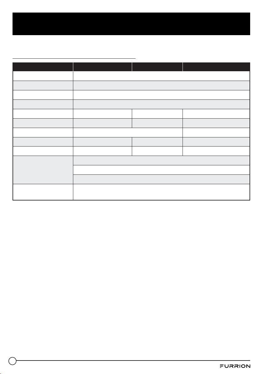
Vision S Family Camera Specification
Model
L/R Side Camera Rear Camera Doorway Camera
Operating Voltage
8 – 30Vdc
Wireless Frequency
2.4G
Wireless Range
>150m (open area)
Delay Time
<250ms
Tx Power
18dBm+/-1.5dBm
Transmitting Speed
6Mbps (Single)
Decompression Form
H.264
Camera Pixel
720x480
CMOS Size
1/3”
IR Cut Filter
850nm automatic
Optical Lens
F2.5 F2.0
View Angle
65° 120°
Image Distance
<12m <5m
Power Consumption
(@12V)
<350mA (IR OFF)
<500mA (IR ON)
Operating Temperature
-20°C to +60°C
Motion Detection
Algorithm
By video camera software
Vision S Family Camera Bracket Specification
LED Marker Marker Light Bracket
Sharkfin
Bracket
Number of
Poles
4 3 2
Wiring Color
Red — Voltage in
Black — GND
Yellow — Turn signal trigger
(left/right)
Brown — Marker Light
Voltage in
Red — Voltage in
Black — GND
Brown — Marker Light
Voltage in
Red — Voltage in
Black — GND
Installation
Position
RED for Rear
Amber for Side (Left/ Right)
RED for Rear
Amber for Side (Left/
Right)
Doorway, Rear

12
Install and Use Monitor
Install and Use 4.3” Monitor
The Furrion Vision S 4.3” monitor is typically cab mounted and used as a rear observation
system together with a Furrion rear camera.
Product overview
Power/Confirm
Antenna
Screen
Up
Menu/Return
Down
Parking Line
Power Indicator
Button Function
● Press briefly to power on.
● Hold for 3 seconds to power off.
● Press briefly to confirm your selection in each menu.
/
● Navigate up /down in each menu.
● Press briefly to switch between camera viewing and menu screens.
● In a submenu, press briefly to return to the previous menu.
P
● Press briefly to show or hide the parking lines.
13
Install and Use Monitor
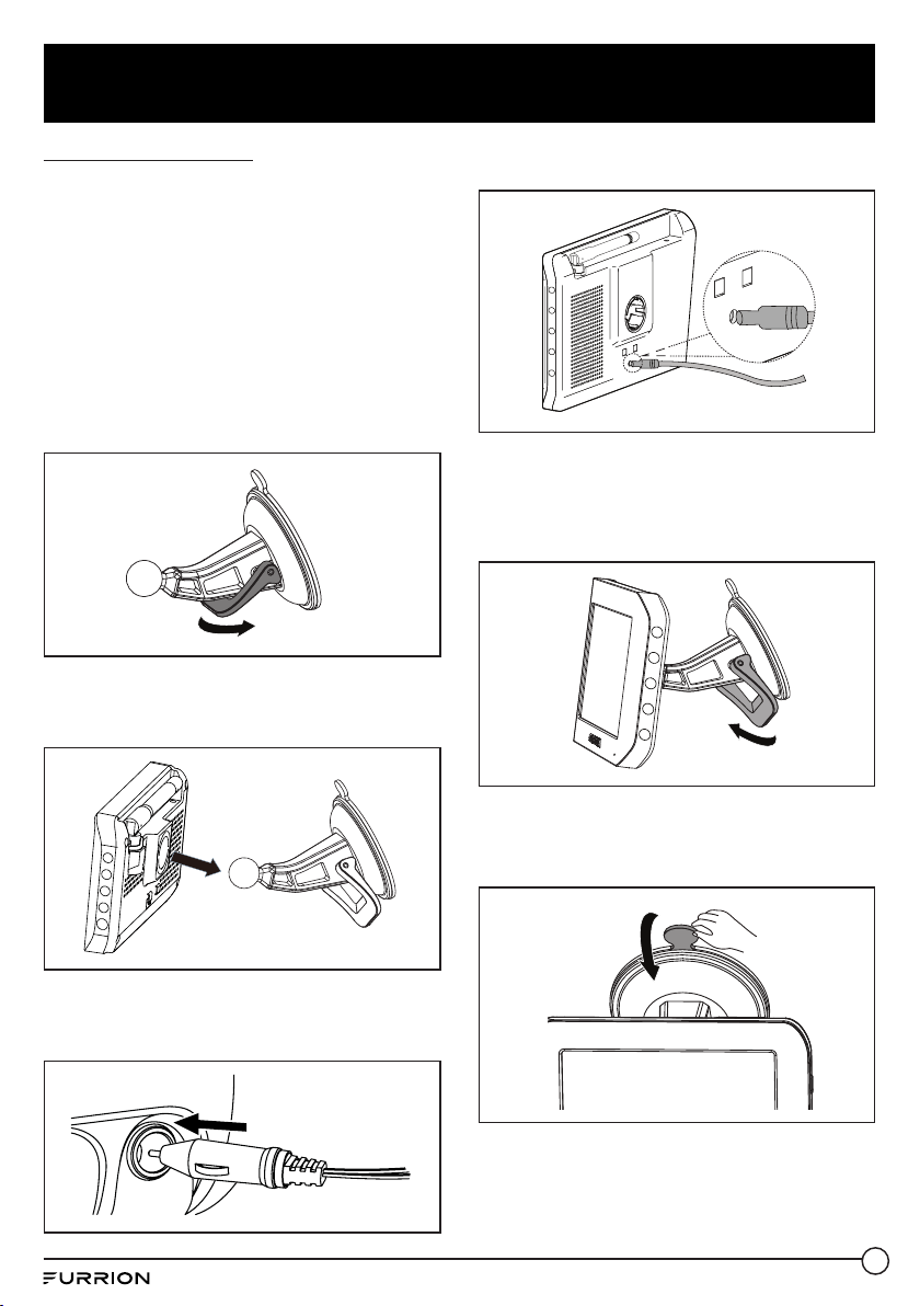
Install the monitor
IMPORTANT: Choose a monitor location
in your vehicle that does not block your
view and complies with local laws for safe
driving. Do not place in an area where it might
interfere with driving.
1. Clean the mounting area and remove the
protective film from the suction cup of the
windshield stand. Then place the suction
cup onto the appropriate location and
push the locking arm downwards to stick
securely.
2. Align the ball on the bracket with the
opening on the back of the monitor and
push firmly to lock into place.
3. Connect the cigarette lighter connector
of the monitor power cable to a cigarette
lighter socket.
4. Connect the DC connector to the power
socket on the monitor.
5. Rotate the monitor to adjust the visual
angle as needed.
To remove the suction cup:
1. Lift up the locking arm.
2. Pull the tab on the suction cup away from
the windshield to allow air in then you can
remove the suction cup easily.

14
Install and Use Monitor
3. Detach the monitor from the windshiled
mount.
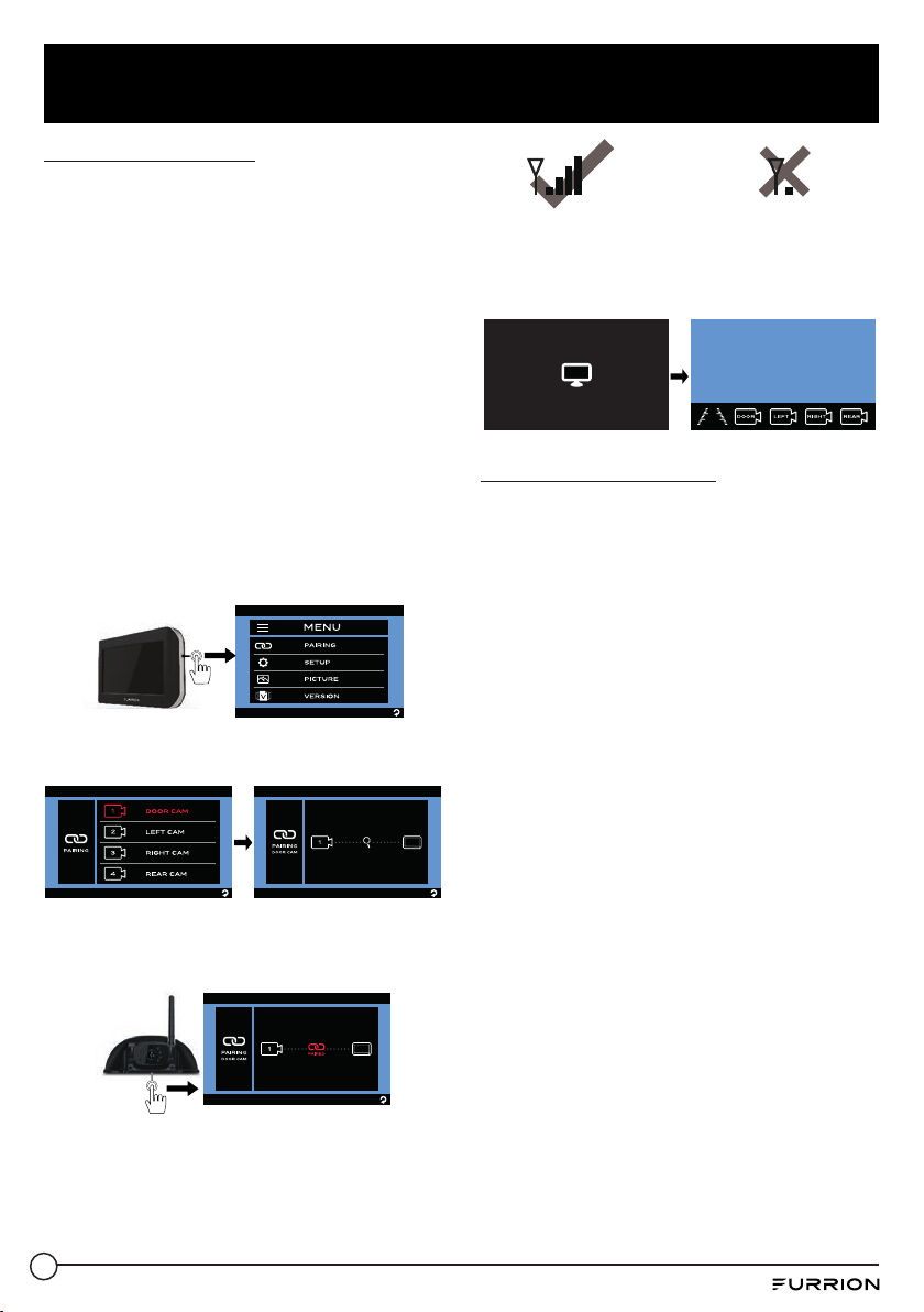
Pair with a rear camera
If this monitor comes in a bundle with a
Furrion Vision S rear camera, it is paired with
the camera by default. If you cannot find the
video from the camera on the monitor screen
or you have a standalone camera, follow the
procedures below for pairing.
1. Ensure you have turned on the monitor
and camera to be paired (see the
installation and wiring section of the
camera for details).
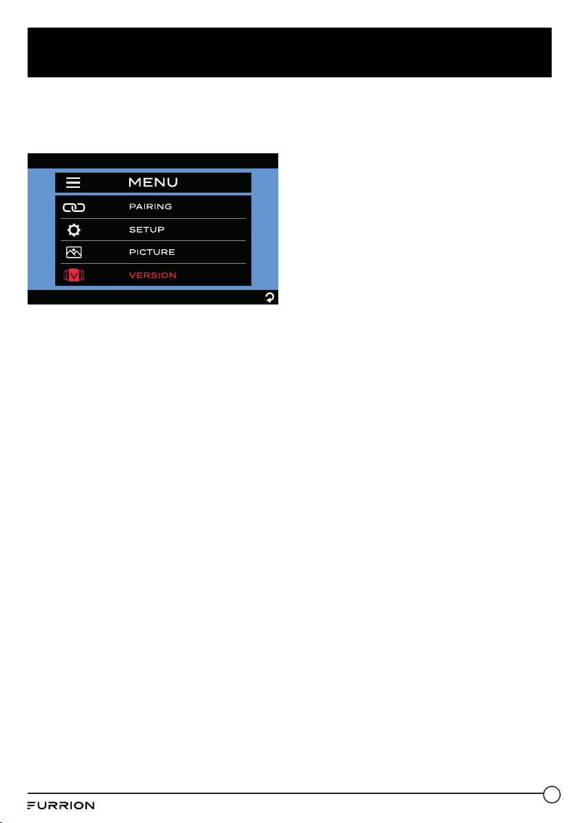
2. Press the MENU button on the right of the
monitor to enter the setup menu.
P
3. Tap PAIRING to enter pairing mode.
4. Press the MONITOR PAIRING button on
the camera (rear camera shown) to pair it
with the monitor.
MONITOR PAIRING
5. Erect antenna (ifavailable) on the camera
and ensure the signal strength is OK.
Good Signal
Poor Signal
Activate the Monitor
When the monitor is off:
Press the
button on the right of the monitor
to turn it on.
When the monitor is on:
Press and hold the
button to activate the
monitor.
NOTES:
− The camera transmits a clear and wide
image with audio from the area behind
the vehicle to the monitor inside. To avoid
unnecessary noise when the vehicle
is moving, you can mute your vehicle
speaker system.
− When the monitor is off, it can turn on
again automatically and display camera
images after receiving a video signal on
the 2.4GHz frequency band from the
camera.
− The monitor adjusts color, brightness,
and contrast automatically for either
daytime or nighttime viewing. At night the
picture will appear black and white. This
is due to the low light level and is normal.
15
Install and Use Monitor
− The monitor in a wireless system is
always watching for a video signal when
it is off. Signals from other wireless
camera systems may cause interference.
For example, security cameras, baby
monitors, and even other backup camera
systems can also trigger the monitor to
briefly light up. This is normal for wireless
products.
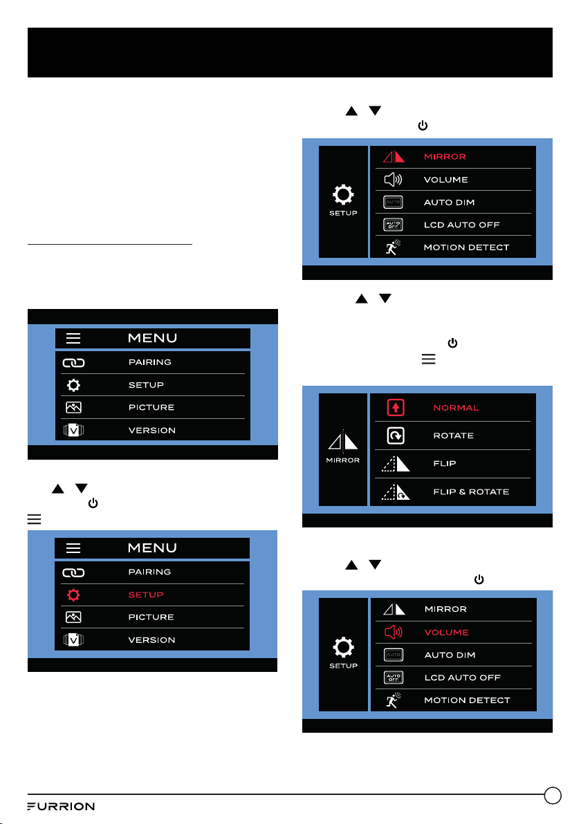
Change Menu Settings
There are four menu options that allow you to
set up the wireless rear observation system
before operation.
Camera Setting
Use
/ to highlight the SETUP menu,
then press to enter the next page or press
to return to the previous page.
Mirror Setting
1. Use
/ to highlight the MIRROR
menu, then press to enter it.
2. Press / to set the camera image
as NORMAL (0
o
), ROTATE (180
o
), FLIP
(Horizontal Mirror) or FLIP & ROTATE
(Vertical Mirror). Press to confirm your
selection or press to return to the
previous page.
Volume Setting
1. Use
/ to highlight the
VOLUMEmenu, then press to enter it.

16
Install and Use Monitor
2. Press to increase volume or press to
decrease volume.
Auto Dim Setting
1. Use
/ to highlight the AUTO DIM
menu, then press to enter it.
2. Use / to select or .
Press to confirm your selection or press
to return to the previous page.
Press or to enable or disable the light
detect function.
LCD Auto Off Setting
1. Use
/ to highlight the LCD AUTO
OFF menu, then press to enter it.
2. Press / to set the LCD auto off time
as 10 SEC, 20 SEC, 30 SEC or (off).
Press to confirm your selection or press
to return to the previous page.
Motion Detect Setting
When this function is enabled while
the monitor is off, it will turn on again
automatically after any motion is detected by
the camera.
1. Use
/ to highlight the MOTION
DETECT menu, then press to enter it.

17
Install and Use Monitor
2. Press / to set the camera detection
sensitivity as LOW, MEDIUM, HIGH or
(off). Press
to confirm your selection or
press
to return to the previous page.
Notes:
− The higher the detection sensitivity the
easier the motion will be detected. Set
MOTION DETECT to HIGH if you want
the camera to be highly sensitive to
objects moving across its detection area.
− In certain situations, the motion of some
objects may cause undesired trigger
actions. This is not a malfunction.
Picture Setting
1. Use
/ to highlight the LCD AUTO
OFF menu, then press to enter it.
2. Use / to highlight the
BRIGHTNESS, CONTRAST or COLOR
menu, then press to enter it.
3. Press or to change the
BRIGHTNESS, CONTRAST or COLOR
setting. Press to confirm your selection
or press to return to the previous page.
Software Version
Use
/ to highlight the VERSION menu,
then press to enter and view the current
software version.

18
Install and Use Monitor
Install and Use 5”/7” Monitor
When mounted in the cab, the Furrion Vision S 5”/7” monitor typically works as an observation
system together with a Furrion rear mounted camera (for rear observation) and two side
cameras (for traffic observation).
When mounted in the coach, the Furrion Vision S 5”/7” monitor typically works as a security
system together with a Furrion doorway camera.
Product overview
Screen
2 Metal
Pins for
Wall Mount
Charging
Antenna
On/Off/Menu
Button
Power Indicator
Speaker
Power Inlet

19
Install and Use Monitor
Prepare
● Prepare tools you may need, including a
#2 Phillips head screwdriver, insulation
tape, pencil and/or a 5/8” drill bit (needed
only when drilling a new hole).
Install the monitor
Mount in cab for observation
IMPORTANT: Choose a monitor location
in your vehicle that does not block your
view and complies with local laws for safe
driving. Do not place in an area where it might
interfere with driving.
1. Choose a mounting method.
When using the windshield stand:
Clean the mounting area and remove
the protective film from the suction cup.
Then place the suction cup onto the
appropriate location and push the locking
arm downwards to stick securely.
When using the table stand: Place the
table stand designed with four non-slip
pads on a stable surface, and route the
monitor power cable as shown.
2. Align the ball on the bracket with the
opening on the back of the monitor and
push firmly to lock into place.
3. Connect the cigarette lighter connector
of the monitor power cable to a cigarette
lighter socket.
NOTE: There is a 12V 1A inline fuse under
the plunger of the cigarette lighter plug.
4. Connect the DC connector to the power
socket on the monitor.
5. Rotate the monitor to adjust the visual
angle as needed.
20
Install and Use Monitor
Pair with a camera
If this monitor comes in a bundle with one or
more Furrion Vision S cameras, it is paired
with the camera(s) by default. If you cannot
find the video from the camera on the monitor
screen or you have a standalone camera,
follow the procedures below for pairing.
Note: For bundles with a sharkfin camera
but no rear camera (such as FOS05TASF /
FOS07TASF), the sharkfin camera is paired
to the REAR CAM channel instead of the
DOOR CAM channel by default.
1. Ensure you have turned on the monitor
and camera(s) to be paired (see the
installation and wiring section of each
camera for details).
2. Press the MENU button on the right of the
monitor to enter the setup menu.
3. Tap PAIRING and then select the camera
to be paired with the monitor.
4. Press the MONITOR PAIRING button
on the camera (doorway security/rear
camera shown) to pair it with the monitor.
5. Repeat the steps to pair the other available
cameras. Erect antennas (ifavailable) on
both the monitor and camera(s). Ensure
the signal strength is OK.
Good Signal
Poor Signal
6. Tap to choose a view mode and then a
camera for view as you like.
MODE
DOOR
REAR
LEFT RIGHT
Activate the Monitor
When the monitor is off:
Press the Menu button on the right of the
monitor to turn it on and enter the menu
setting page.
When the monitor is on:
Press and hold the Menu button to activate
the menu setting page.
NOTES:
− The rear or doorway camera transmits a
clear and wide image with audio from the
area behind the vehicle or at the vehicle
door to the monitor inside. To avoid
unnecessary noise when the vehicle
is moving, you can mute your vehicle
speaker system.
− The side cameras transmit clear images
at both sides of your vehicle to the
monitor.
− When the monitor is off, it can turn on
again automatically and display camera
images after receiving a video signal
on the 2.4GHz frequency band from a
camera.
− The monitor adjusts color, brightness,
and contrast automatically for either
daytime or nighttime viewing. At night the
picture will appear black and white. This
is due to the low light level and is normal.
− The monitor in a wireless system is
always watching for a video signal when

21
Install and Use Monitor
it is off. Signals from other wireless
camera systems may cause interference.
For example, security cameras, baby
monitors, and even other backup camera
systems can also trigger the monitor to
briefly light up. This is normal for wireless
products.
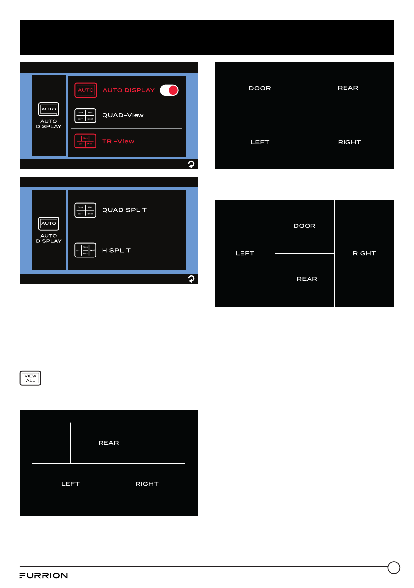
Touchscreen operation
When in quadrant mode:
IMPORTANT: Quad view mode is not
recommended for observation while you
are driving.
1. Tap the center of the monitor screen to
show the
MODE
icon.
2. Tap
MODE
to switch between TRI-View,
QUAD SPLIT and H SPLIT.
MODE
DOOR
REAR
LEFT RIGHT
MODE
DOOR
RIGHT
REAR
LEFT
MODE
RIGHT
REAR
LEFT
MODE
DOOR
REAR
LEFT RIGHT
MODE
DOOR
RIGHT
REAR
LEFT
MODE
RIGHT
REAR
LEFT
MODE
DOOR
REAR
LEFT RIGHT
MODE
DOOR
RIGHT
REAR
LEFT
MODE
RIGHT
REAR
LEFT
3. Tap DOOR (not available in TRI-View
mode), LEFT, RIGHT or REAR to select a
camera and view the image fromit.
When in single channel mode:
Tap once on the monitor screen to bring up
the camera selection interface.
MODE
DOOR
REAR
LEFT RIGHT
MODE
DOOR
RIGHT
REAR
LEFT
MODE
RIGHT
REAR
LEFT
Icon Description
Tap to turn on/off the on-screen
guideline.
● In multi channel mode with DOOR,
LEFT and RIGHT selected, tap
to enter Parking mode with
on-screen guideline.
● In single channel mode with REAR
selected, tap once to enter the
parking lines of rear view; tap twice
to enter Parking mode with on-
screen guideline.
The selected mode will remain for
30 seconds before returning to the
previous mode.
Tap to select the door camera.
Tap to select the left camera.
Tap to select the right camera.
Tap to select the rear camera.
Tap twice on the monitor screen to show the
control menu. It will stay 5 seconds, then go
back to previous single camera view.
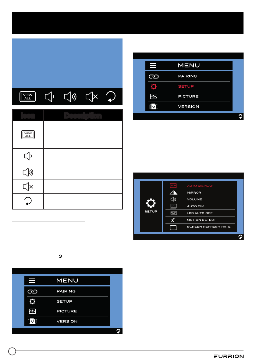
22
Install and Use Monitor
Icon Description
Tap to enter quadrant mode.
The selected mode will remain
for 10 seconds before returning to
the previous single channel mode.
Tap to decrease the volume of
the monitor.
Tap to increase the volume of
the monitor.
Tap to mute the monitor.
Tap to return to the previous
page.
Change Menu Settings
There are four options that allow you to set
up the wireless vehicle observation / security
system before operation.
Tap one of the four options to enter the
setting page or tap
to return to the previous
page.
Camera Setting
Tap SETUP to highlight it in red and enter the
submenu automatically.
Auto Display Setting
When this function is enabled, the monitor
can switch back to single-channel display
mode automatically after the monitor stays in
3-channel or 4-channel display mode for 10
seconds.
1. Tap AUTO DISPLAY to enter the submenu.
2. Tap the AUTO DISPLAY switch to
highlight it red and enable this function.
Here, you can tap QUAD-View to enter
the sub-menu and select QUAD SPLIT
or H SPLIT camera layout for 4-channel
display or tap TRI-View to select the
camera layout pattern for 3-channel
display.
23
Install and Use Monitor
By default, the monitor screen shows the
single-channel image of the last paired
camera.
To switch to 3-channel or 4-channel
display mode:
Tap twice on the monitor screen to bring
up the camera selection interface, then tap
to enter channel display.
− 3-channel display when TRI-View is
selected:
− 4-channel display when QUAD SPLIT is
selected:
− 4-channel display when H SPLIT is
selected:
On the channel display interface, you can
tap a specific section to enter the respective
single-channel display mode, no matter
whether the AUTO DISPLAY switch is
enabled or disabled.
Mirror Setting

24
Install and Use Monitor
1. Tap MIRROR to enter the submenu.
The currently selected setting will be
highlighted red.
2. Select the camera you are going to set.
3. Tap to set the camera image rotation
angle as NORMAL (0
o
), ROTATE (180
o
),
FLIP (Horizontal Mirror) or FLIP &
ROTATE (Vertical Mirror).
4. Repeat steps 2 and 3 to set the other
cameras.
Volume Setting
1. Tap VOLUME to enter the submenu.
2. Tap or to decrease or increase
the volume of the doorway and/or rear
cameras.
Auto Dim Setting
1. Tap AUTO DIM to enter the submenu.
2. Tap or to enable or disable automatic
screen brightness adjustment.

25
Install and Use Monitor
LCD Auto Off Setting
1. Tap LCD AUTO OFF to enter the
submenu.
2. Tap to set the LCD auto off time as 10
SEC, 20 SEC, 30 SEC or (off).
When the LCD display is off, you can
press the Menu button on the right of the
monitor to resume display.
Motion Detect Setting
When this function is enabled while
the monitor is off, it will turn on again
automatically after any motion is detected by
a camera.
1. Tap MOTION DETECT to enter the
submenu.
2. Tap to set the camera detection
sensitivity as LOW, MEDIUM, HIGH or
(off).
Notes:
− The higher the detection sensitivity the
easier the motion will be detected. Set
MOTION DETECT to HIGH if you want
the camera to be highly sensitive to
objects moving across its detection area.
− In certain situations, the motion of some
objects may cause undesired trigger
actions. This is not a malfunction.

26
Install and Use Monitor
Screen Refresh Rate Setting
Here you can set a suitable screen refresh
rate for the monitor. Screen refresh rate
indicates the number of times in a second
that the monitor redraws the screen image.
1. Tap SCREEN REFRESH RATE to enter
the submenu.
2. Tap to set the screen refresh rate to 60Hz
or 50Hz.
Picture Setting
1. Tap PICTURE to highlight it in red and
enter the submenu automatically.
2. Select the camera you are going to set.
3. Tap BRIGHTNESS, CONTRAST or
COLOR to enter the submenu.
4. Tap or to change the settings.
5. Repeat steps 2 to 4 to change the other
camera(s) settings.
27
Install and Use Monitor
Software Version
● Tap VERSION to show the software
version of the monitor and the current
paired camera(s).

28
Install Cameras
Install Doorway Security/Rear Camera
Product overview
8 IR LEDs
LED Indicator
Lens
Monitor Pairing
Button
Light Sensor
Antenna
Prepare
● Prepare tools you may need, including a #2 Phillips head screwdriver, sealant, insulation
tape, pencil and/or a 5/8”drill bit (needed only when drilling a new hole).
Mount bracket
Note: Skip this section if your RV is pre-installed with a bracket for camera installation.
IMPORTANT: Before any installation and wiring operation, remove the key from the ignition
and isolate the 12V / 24V power source.
Always seek professional assistance if you are unsure about the installation and wiring
operation.
1. Determine the mounting location on your RV. Ensure that there is no obstacle blocking the
camera view. The recommended mounting location is shown below:
− For rear camera position:
At the top center on the rear of your RV and as high as practicable (2” below the red
marker light if available).
− For doorway camera position:
Above the top of the door.
Note: The RV shown here is for reference only. You can mount Furrion Vision S products onto
various types of RVs such as trailers and Class A/B/C motorhomes.

29
Install Cameras
≥ 2”
Doorway camera position
Rear camera
position
2. Use the gasket as a template to mark a
basic outline on the chosen location with
a pencil. Drill a 5/8” center hole. Then
route the female connector of the camera
power cable through the hole and leave
2inches of slack.
5
/
8
”
2 ”
5/8”
3. Connect the bare ends of the camera
power cable to the nearest 12V / 24V
power supply.
− For rear camera position:
You are suggested to share the same
power line from the nearest marker light
(such as the red marker light at the top
center on the rear if available).
− For doorway camera position:
You are suggested to share the power
line from your RV porch light (or the
nearest light source from the RV/trailer
battery).
Note: Ensure that the fuse on the connected
power line provides additional 1A fusing
current for the camera. Ensure proper cable
isolation for all bare ends (e.g., by using
insulation tape).
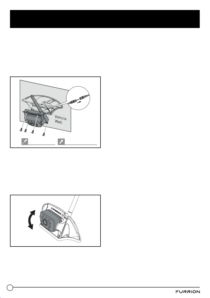
4. Fix the gasket and bracket with four
#6x3/4“ flat self-tapping screws. If the
mounting surface is uneven, apply sealant
between the gasket and RV surface,
and around the 5/8” holes at the screw
locations for better sealing.
#2 Phillips head #6x
3
/
4
" flat self-tapping
Mount camera
If this camera comes in a bundle with a
Furrion Vision S monitor, it is paired with the
monitor by default. You can connect it to the
female connector on the Y type power cable
of the monitor and resume power temporarily
to check the pairing status before installation.
If you cannot find the video of the camera on
the monitor screen or you have an unbundled
camera, see the monitor installation and
usage section for the pairing procedures.
1. Mount the antenna onto the camera
securely and keep the antenna straight.
Torque: ≤8 In-lbs
30
Install Cameras
2. If there is a cover on the bracket housing,
remove it first. Connect the female
connector of the camera power cable to
the male connector on the back of the
camera, and put the redundant cables
inside the bracket housing. Then attach
the camera to the bracket with four
#4x1/4” self-tapping screws.
#2 Phillips head #4x
1
/
4
" self-tapping
3. Adjust the view angle of the camera
by rotating it upwards and downwards
(0~50°) so that you can see:
(For rear camera position): the bottom
edge of your vehicle and the road
conditions behind;
(For doorway camera position): the
bottom edge of the door.
31
Install Cameras
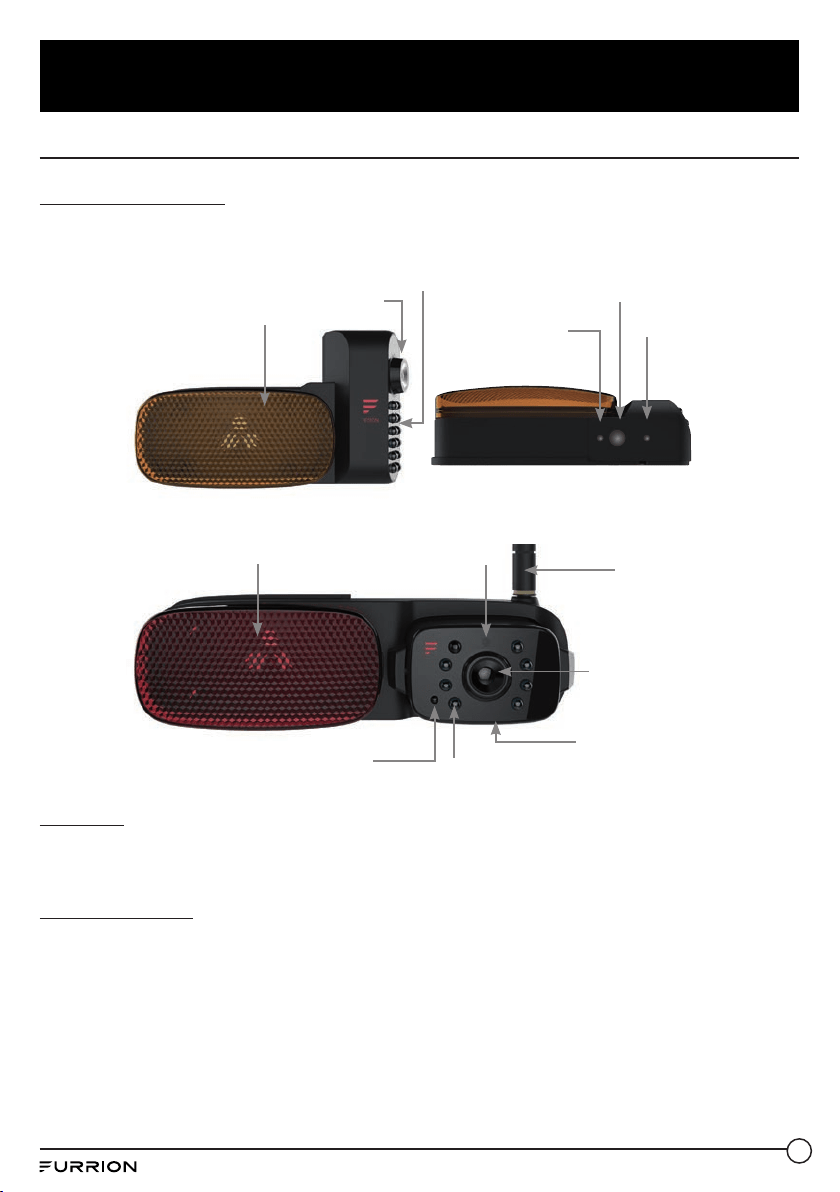
Install Side Cameras & Rear Camera withMarker Light
Product overview
Side (Left/Right) cameras with marker light
12 IR LED Light
LED Indicator
Monitor Pairing
Button
Light Sensor
Lens
Marker Light
Rear camera
8 IR LED
LED Indicator
Lens
Monitor Pairing
Button
Light Sensor
Marker Light
Antenna
Prepare
● Prepare tools you may need, including # 1 and #2 Phillips head screwdrivers, sealant,
insulation tape, pencil and/or a 5/8”drill bit (needed only when drilling a new hole).
Mount bracket
Note: Skip this section if your RV is pre-installed with a bracket for camera installation.
IMPORTANT: Before any installation and wiring operation, remove the key from the ignition
and isolate the 12V / 24V power source.
Always seek professional assistance if you are unsure about the installation and wiring operation.
1. Determine the mounting location on your RV. Ensure that there is no obstacle blocking the
camera view. To avoid drilling new holes, you are recommended to replace the original
marker lights with Furrion products directly as shown below:
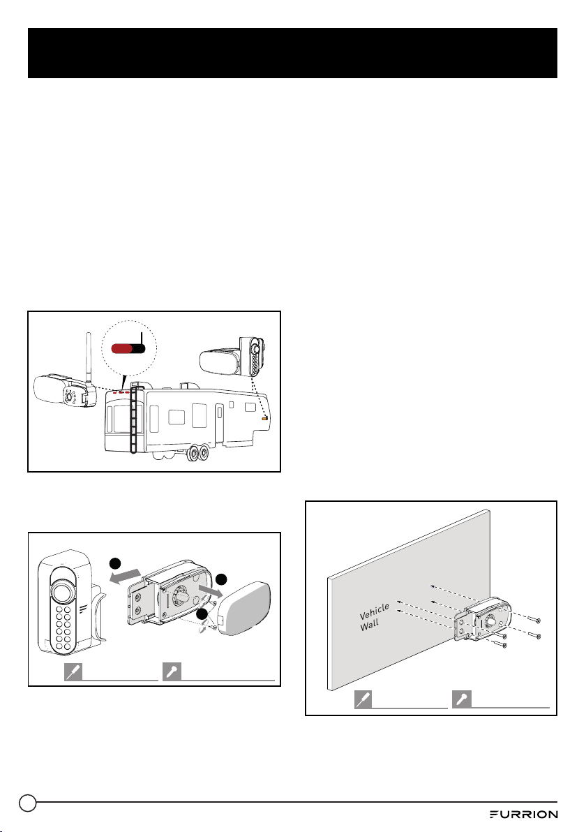
32
Install Cameras
− For rear camera position: Location
of the original rear marker light at the
top center on the rear of your RV. To
accommodate the camera, ensure that
there is at least 7.5” space between
the central points of the two adjacent
marker lights.
− For side camera position: Location of
the original side marker lights (as front
as possible).
Note: The RV shown here is for reference
only. You can mount Furrion Vision S
products onto various types of RVs such as
trailers and Class A/B/C motorhomes.
Rear camera
position
Side camera
position
2. Remove the lens cover and detach the
camera from the marker light bracket
(right side camera shown).
3
1
2
#4x
1
/
4
" self-tapping
#1 Phillips head
3. Remove the original marker light from the
corresponding location.
4. Connect the bare ends of the power cable
on the back of the bracket to the nearest
12V/24V power supply: red_camera/
brown_marker light: +; black_grounding: -
− For rear camera position: You are
suggested to use the power line for the
original rear marker light directly.
− For left/right side camera position:
You are suggested to use the power
line for the original side marker lights
directly.
Note: Ensure that the fuse on the connected
power line provides additional 1A fusing
current for the camera.
Ensure proper cable isolation for all bare
ends (e.g., by using insulation tape).
5. Secure the gasket and marker light
bracket onto your vehicle using four flat
head #6x3/4”self-drilling screws. If the
mounting surface is uneven, apply sealant
between the gasket and RV surface,
and around the 5/8’’ holes at the screw
locations for better sealing.
#6x
3
/
4
" flat head
#2 Phillips head
33
Install Cameras
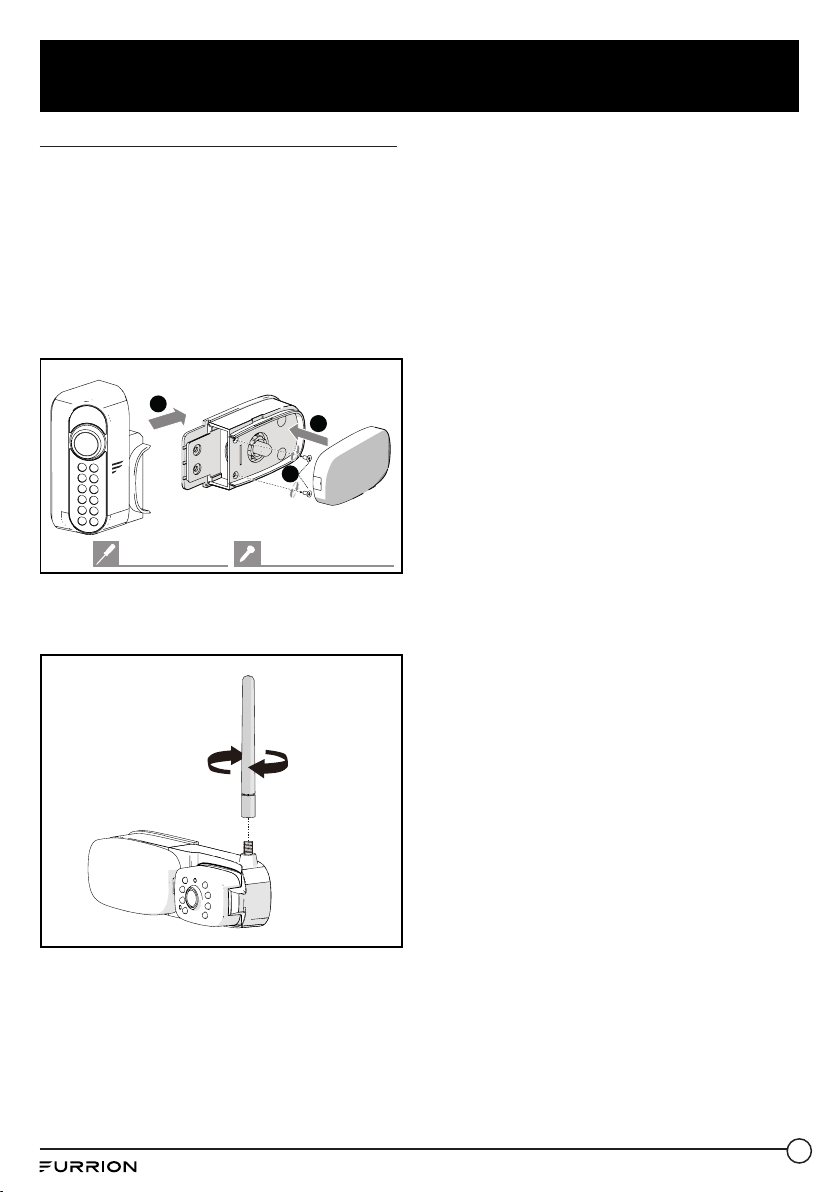
Mount cameras (right side shown)
1. Reattach the camera to the marker light
bracket. Before fixing the camera, check
its pairing status with the monitor by
resuming power temporarily.
If you cannot find the video from the
camera on the monitor screen or you have
an unbundled camera, see the monitor
installation and usage section for pairing
procedures.
1
3
2
#4x
1
/
4
" self-tapping
#1 Phillips head
For the rear camera, mount the antenna
onto the camera securely and keep the
antenna straight.
Torque: ≤8 In-lbs
2. For the left/right side camera,
ensure that the lens on the camera
face backwards after installation, with
the MONITOR PAIRING button at the
bottom.
For the rear camera, adjust the view
angle of the camera by rotating it upwards
and downwards (0~50°) so that you can
see the bottom edge of your vehicle and
the road conditions behind.

34
Troubleshooting
Problem Solution
Monitor won’t turn on (no
blue LED)
Check the power cable is connected.
Check that the power supply has 12-24V DC output.
Check all fuses and breakers (including fuses in the cigarette power
adapter and fuse box).
Power off and on again to reset.
Wireless camera(s) and
monitor won’t pair
Furrion monitor / rearview mirror can only pair with Furrion cameras.
Pairing with products from other manufacturers is not supported.
Check if the camera is receiving power.
− Ensure that the fuse on the connected power line provides
additional 1A fusing current for the camera.
− Ensure proper cable isolation for all bare ends to avoid short-
circuit.
Make sure to hold the camera pairing button for 2 seconds.
Intermittent / weak
signal icon appears
Check if the camera antenna is fitted and secured correctly - it
should be vertical.
Large dense objects could be obscuring the signal. If possible, move
the objects.
Interference from electrical appliances may be affecting the wireless
signal. Turn off the appliances when using the system.
Interference from overhead power lines may be affecting the signal.
Try unpairing and pairing again.
Blurry images on the
monitor
Remove the protective film from the camera lens upon completion of
installation.
The camera lens may be dirty. Wipe them with a piece of soft and
clean cloth.
Some adverse weather conditions such as heavy fog, rain, floating
dust or mud splashes may either partially or entirely block the camera
view. Clean the camera lens immediately after driving to a safe place.
Images too dark / bright
on the monitor
Adjust the brightness and contrast settings.
The image may be too bright when the camera lens are facing
towards a direct light source. This is not a malfunction.
Night vision is poor or
does not function
The light sensor on the camera may be dirty or obstructed. Clean the
light sensor or remove obstacles.
If the ambient light is too strong, the night vision function may not
engage. This is not a malfunction.
Ensure that the camera is installed at least 2 inches away from
marker lights.

35
Troubleshooting
Problem Solution
Monitors Blue LED off
with no picture
The camera has no power connected.
Ensure the tow vehicle is running.
Ensure the 7 way connector is connected.

IM-FCM00007 V3.0
Furrion Innovation Center & Institute of Technology
● 52567 Independence Ct., Elkhart, IN 46514, USA ● Toll free:1-800-789-3341
● Email: [email protected]
©2007-2021 Furrion Ltd. Furrion® and the Furrion logo are trademarks licensed for use by Furrion
Ltd. and registered in the U.S. and other countries.
For Patent Info: www.furrion.com/pages/patents
www.furrion.com
