Tarraco
Owner’s manual
5FJ012720BM
Inglés
5FJ012720BM (06.22)
SEAT Tarraco Inglés (06.22)

SEAT S.A. is permanently concerned about continuous development of its types and models. For this reason we ask you to understand,
that at any given time, changes regarding shape, equipment and technique may take place on the car delivered. For this reason no
right at all may derive based on the data, drawings and descriptions in this current handbook.
All texts, illustrations and standards in this handbook are based on the status of information at the time of printing. Except for error or
omission, the information included in the current handbook is valid as of the date of closing print.
Re-printing, copying or translating, whether total or partial is not allowed unless SEAT allows it in written form.
SEAT reserves all rights in accordance with the “Copyright” Act.
All rights on changes are reserved.
❀
This paper has been manufactured using bleached non-chlorine cellulose.
© SEAT S.A. - Reprint: 15.06.22
Vehicle identification data
Model:
Vehicle Registration:
Vehicle identification
number:
Date of vehicle registration
or vehicle delivery:
SEAT Official Service:
Service advisor:
Telephone:
Confirmation of receipt of documentation
and vehicle keys
The following items were delivered
with the vehicle:
YES NO
On-board documentation
First key
Second key
Correct working order of all keys was
checked
Location:
Date:
Signature of owner:

Thank you for your con-
fidence
With your ne
w SEAT, you will be able to enjoy
a vehicle with state-of-the-art technology and
top quality features.
We recommend reading this Instruction Manual
carefully to learn more about your vehicle so
you can enjoy all its benefits in your daily driv-
ing.
Information about handling is complemented
with instructions regarding the operation and
maintenance of the vehicle in order to ensure
its safety and maintain its value. Moreover, we
want to give you valuable advice and tips to
drive your vehicle eciently and respecting the
environment.
We wish you safe and enjoyable motoring.
SEAT, S.A.
WARNING
Read and always observe safety informa-
tion concerning the passenger
's front airbag
›››page57, Fitting and using child seats.

2
Table of Contents
Table of Contents
About this instruction manual . . . . . . . 4
General views of the vehicle . . . . . . . . . 6
Front exterior view . . . . . . . . . . . . . . . . . . . . . . . . . . . . 6
Rear exterior view . . . . . . . . . . . . . . . . . . . . . . . . . . . . 7
Interior view . . . . . . . . . . . . . . . . . . . . . . . . . . . . . . . . . . 8
Overview (left hand drive) . . . . . . . . . . . . . . . . . . . . 9
Overview (right hand drive) . . . . . . . . . . . . . . . . . . 10
Driver information . . . . . . . . . . . . . . . . . . . . 11
Control lamps . . . . . . . . . . . . . . . . . . . . . . . . . . . . . . . . 11
Instrument panel . . . . . . . . . . . . . . . . . . . . . . . . . . . . . 13
Instrument cluster operation . . . . . . . . . . . . . . . . . 32
Infotainment system operation and displays . 33
Safety . . . . . . . . . . . . . . . . . . . . . . . . . . . . . . . . 38
Safe driving . . . . . . . . . . . . . . . . . . . . . . . . . . . . . . . . . . 38
Correct sitting position of vehicle occupants . 39
Seat belts . . . . . . . . . . . . . . . . . . . . . . . . . . . . . . . . . . . . 41
PreCrash system . . . . . . . . . . . . . . . . . . . . . . . . . . . . . 47
Airbag system . . . . . . . . . . . . . . . . . . . . . . . . . . . . . . . . 49
Transporting children safely . . . . . . . . . . . . . . . . . . 55
In case of emergency . . . . . . . . . . . . . . . . . . . . . . . . 65
High-voltage battery . . . . . . . . . . . . . . . . 69
Safety instructions . . . . . . . . . . . . . . . . . . . . . . . . . . . 69
Conservation of the high-voltage battery . . . . 71
Charging the high-voltage battery . . . . . . . . . . . 71
Charging settings in the infotainment system . 77
Charging cable . . . . . . . . . . . . . . . . . . . . . . . . . . . . . . 78
Opening and closing . . . . . . . . . . . . . . . . . 82
Set of vehicle keys . . . . . . . . . . . . . . . . . . . . . . . . . . . 82
Keyless Access system . . . . . . . . . . . . . . . . . . . . . . . 84
Central locking . . . . . . . . . . . . . . . . . . . . . . . . . . . . . . . 86
Anti-theft alarm . . . . . . . . . . . . . . . . . . . . . . . . . . . . . . 90
Doors . . . . . . . . . . . . . . . . . . . . . . . . . . . . . . . . . . . . . . . . 92
Rear lid . . . . . . . . . . . . . . . . . . . . . . . . . . . . . . . . . . . . . . . 94
Window controls . . . . . . . . . . . . . . . . . . . . . . . . . . . . . 98
Sunroof . . . . . . . . . . . . . . . . . . . . . . . . . . . . . . . . . . . . . . 101
Steering wheel . . . . . . . . . . . . . . . . . . . . . . . 105
Multifunction steering wheel . . . . . . . . . . . . . . . . . 105
Seats and head restraints . . . . . . . . . . . 107
Front seats . . . . . . . . . . . . . . . . . . . . . . . . . . . . . . . . . . . 107
Rear seats . . . . . . . . . . . . . . . . . . . . . . . . . . . . . . . . . . . 110
Headrest . . . . . . . . . . . . . . . . . . . . . . . . . . . . . . . . . . . . . 111
Seat functions . . . . . . . . . . . . . . . . . . . . . . . . . . . . . . . . 114
Lights . . . . . . . . . . . . . . . . . . . . . . . . . . . . . . . . . 118
Vehicle lighting . . . . . . . . . . . . . . . . . . . . . . . . . . . . . . . 118
Interior lights . . . . . . . . . . . . . . . . . . . . . . . . . . . . . . . . . 123
Visibility . . . . . . . . . . . . . . . . . . . . . . . . . . . . . . 125
Windscreen wiper and rear window wiper sys-
t
ems . . . . . . . . . . . . . . . . . . . . . . . . . . . . . . . . . . . . . . . . . 125
Mirrors . . . . . . . . . . . . . . . . . . . . . . . . . . . . . . . . . . . . . . . 127
Sun protection . . . . . . . . . . . . . . . . . . . . . . . . . . . . . . . 130
Air conditioning . . . . . . . . . . . . . . . . . . . . . . 131
Heating, ventilation and cooling . . . . . . . . . . . . . . 131
Auxiliary heating and ventilation . . . . . . . . . . . . . . 140
Driving . . . . . . . . . . . . . . . . . . . . . . . . . . . . . . . . 145
Driving indications . . . . . . . . . . . . . . . . . . . . . . . . . . . 145
Starting and stopping the engine . . . . . . . . . . . . . 150
Driving with electric drive . . . . . . . . . . . . . . . . . . . . 154
Operating mode selection . . . . . . . . . . . . . . . . . . . 156
Start-Stop system . . . . . . . . . . . . . . . . . . . . . . . . . . . . 158
Manual gearbox . . . . . . . . . . . . . . . . . . . . . . . . . . . . . 160
DSG automatic transmission . . . . . . . . . . . . . . . . . 161
Driving on slopes . . . . . . . . . . . . . . . . . . . . . . . . . . . . . 168
Steering . . . . . . . . . . . . . . . . . . . . . . . . . . . . . . . . . . . . . . 169
SEAT Drive Pr
ofiles . . . . . . . . . . . . . . . . . . . . . . . . . . . 170
Braking system . . . . . . . . . . . . . . . . . . . . . . . . . . . . . . . 172
Brake assist systems . . . . . . . . . . . . . . . . . . . . . . . . . 174
Assistant systems . . . . . . . . . . . . . . . . . . . . 178
General notes . . . . . . . . . . . . . . . . . . . . . . . . . . . . . . . . 178
Drive assist sensors and cameras . . . . . . . . . . . . 179
Cruise control system . . . . . . . . . . . . . . . . . . . . . . . . 182
Speed limiter . . . . . . . . . . . . . . . . . . . . . . . . . . . . . . . . . 184
ACC - Adaptive Cruise Control . . . . . . . . . . . . . . 185
Predictive speed adjustment . . . . . . . . . . . . . . . . . 191
emergency brake assistance system (Front
Assist)
. . . . . . . . . . . . . . . . . . . . . . . . . . . . . . . . . . . . . . . . 193
Lane Assist system . . . . . . . . . . . . . . . . . . . . . . . . . . . 196
Driving Assist (Travel Assist) . . . . . . . . . . . . . . . . . . 198
Emergency Assist . . . . . . . . . . . . . . . . . . . . . . . . . . . . 201
Lane departure warning (Side Assist) . . . . . . . . . 202
Parking and manoeuvring . . . . . . . . . . . 206
Park the vehicle . . . . . . . . . . . . . . . . . . . . . . . . . . . . . . 206
Electronic parking brake . . . . . . . . . . . . . . . . . . . . . 207
General information on parking systems . . . . . 209
Parking aid Plus . . . . . . . . . . . . . . . . . . . . . . . . . . . . . . 210
Rear parking aid . . . . . . . . . . . . . . . . . . . . . . . . . . . . . 214
Parking aid system (Park Assist) . . . . . . . . . . . . . . 216
Reverse Assist (Rear View Camera) . . . . . . . . . . 223
Peripheral view system (Top View Camera) . . 226
Trailer Assist . . . . . . . . . . . . . . . . . . . . . . . . . . . . . . . . . . 230
Rear cross tr
ac alert (RCTA) . . . . . . . . . . . . . . . . 233
Practical equipment . . . . . . . . . . . . . . . . . 235
Storage compartment . . . . . . . . . . . . . . . . . . . . . . . 235
Power sockets . . . . . . . . . . . . . . . . . . . . . . . . . . . . . . . . 239
Data transmissions . . . . . . . . . . . . . . . . . . . 242
SEAT CONNECT . . . . . . . . . . . . . . . . . . . . . . . . . . . . . 242
Privacy mode . . . . . . . . . . . . . . . . . . . . . . . . . . . . . . . . 246
WLAN access point . . . . . . . . . . . . . . . . . . . . . . . . . . . 247

Table of Contents
3
Full Link . . . . . . . . . . . . . . . . . . . . . . . . . . . . . . . . . . . . . . 248
Wired and wireless connections . . . . . . . . . . . . . . 253
Infotainment system . . . . . . . . . . . . . . . . . 254
First steps . . . . . . . . . . . . . . . . . . . . . . . . . . . . . . . . . . . . 254
Overview and controls . . . . . . . . . . . . . . . . . . . . . . . 257
General instructions for use . . . . . . . . . . . . . . . . . . 259
Voice control . . . . . . . . . . . . . . . . . . . . . . . . . . . . . . . . . 264
Radio mode . . . . . . . . . . . . . . . . . . . . . . . . . . . . . . . . . . 266
Media Mode . . . . . . . . . . . . . . . . . . . . . . . . . . . . . . . . . 270
Navigation . . . . . . . . . . . . . . . . . . . . . . . . . . . . . . . . . . . 273
Telephone interface . . . . . . . . . . . . . . . . . . . . . . . . . . 280
Storing objects . . . . . . . . . . . . . . . . . . . . . . . 286
Positioning the luggage and cargo . . . . . . . . . . . 286
Luggage compartment . . . . . . . . . . . . . . . . . . . . . . 287
Net partition . . . . . . . . . . . . . . . . . . . . . . . . . . . . . . . . . . 291
Luggage compartment equipment . . . . . . . . . . . 293
Roof carrier . . . . . . . . . . . . . . . . . . . . . . . . . . . . . . . . . . 295
Trailer mode . . . . . . . . . . . . . . . . . . . . . . . . . . . . . . . . . . 297
Fuel and exhaust gas cleaning . . . . . . 308
Refuelling . . . . . . . . . . . . . . . . . . . . . . . . . . . . . . . . . . . . 308
Fuel types . . . . . . . . . . . . . . . . . . . . . . . . . . . . . . . . . . . . 310
AdBlue® . . . . . . . . . . . . . . . . . . . . . . . . . . . . . . . . . . . . . . 311
Engine management and emissions control
syst
em . . . . . . . . . . . . . . . . . . . . . . . . . . . . . . . . . . . . . . . 313
Miscellaneous situations . . . . . . . . . . . . 316
Vehicle tool kit . . . . . . . . . . . . . . . . . . . . . . . . . . . . . . . . 316
Changing the windscreen wiper blades . . . . . . 316
Jump start . . . . . . . . . . . . . . . . . . . . . . . . . . . . . . . . . . . 318
Towing the vehicle . . . . . . . . . . . . . . . . . . . . . . . . . . . 320
Fuses . . . . . . . . . . . . . . . . . . . . . . . . . . . . . . . . . . . . . . . . . 324
Changing bulbs . . . . . . . . . . . . . . . . . . . . . . . . . . . . . . 328
Checking and r
efilling levels . . . . . . . . 329
Engine compartment . . . . . . . . . . . . . . . . . . . . . . . . . 329
Fluids and consumables . . . . . . . . . . . . . . . . . . . . . 332
Cooling system . . . . . . . . . . . . . . . . . . . . . . . . . . . . . . 332
Brake fluid . . . . . . . . . . . . . . . . . . . . . . . . . . . . . . . . . . . . 335
Windscreen washer reservoir . . . . . . . . . . . . . . . . . 336
Engine oil . . . . . . . . . . . . . . . . . . . . . . . . . . . . . . . . . . . . . 337
12-volt battery . . . . . . . . . . . . . . . . . . . . . . . . . . . . . . . 341
Energy management . . . . . . . . . . . . . . . . . . . . . . . . . 345
Wheels and tyres . . . . . . . . . . . . . . . . . . . . . 347
Important information about wheels and
t
yres . . . . . . . . . . . . . . . . . . . . . . . . . . . . . . . . . . . . . . . . . 347
Changing a wheel . . . . . . . . . . . . . . . . . . . . . . . . . . . 353
Tyre pressure monitor system . . . . . . . . . . . . . . . . 359
Tyre repair . . . . . . . . . . . . . . . . . . . . . . . . . . . . . . . . . . . 360
Maintenance . . . . . . . . . . . . . . . . . . . . . . . . . 364
Service . . . . . . . . . . . . . . . . . . . . . . . . . . . . . . . . . . . . . . . 364
Additional service oers . . . . . . . . . . . . . . . . . . . . . . 366
Vehicle upkeep and cleaning . . . . . . . . . . . . . . . . . 367
Accessories, spare parts and repair work . . . . . 372
Information for the user . . . . . . . . . . . . . . 375
Warranty . . . . . . . . . . . . . . . . . . . . . . . . . . . . . . . . . . . . . 375
Information stored by the control units . . . . . . . 375
Vehicle antennas . . . . . . . . . . . . . . . . . . . . . . . . . . . . . 376
Materials and recycling information . . . . . . . . . . 376
Radioelectrical equipment . . . . . . . . . . . . . . . . . . . 377
Technical data . . . . . . . . . . . . . . . . . . . . . . . 382
Indications about the technical data . . . . . . . . . 382
Index . . . . . . . . . . . . . . . . . . . . . . . . . . . . . . . . . . 389
4
About this instruction manual
About this instruction
manual
This instruction manual is v
alid for all variants
and versions of your SEAT model. It describes
all equipment and models without specifying
whether they are optional equipment or model
variants. As a result, equipment not fitted to
your vehicle or only available in certain coun-
tries may be described. Find out about your
vehicle's equipment in the documentation sup-
plied with it and please contact your SEAT Of-
ficial SEAT Service if you require more detailed
information.
All information provided in instruction manual
corresponds to the information available at the
time of going to press. As the vehicle is under
continuous development, it may have dieren-
ces to the data included in this manual. For this
reason, no claims can be made in the event
of mismatching data, illustrations and descrip-
tions.
Ensure that the on-board documentation is kept
in the vehicle at all times if you sell it or lend it to
third parties. In addition, SEAT recommends re-
setting the infotainment system to factory set-
tings to delete all personal data.
Some details on the drawings may be dierent
to your vehicle and they should be interpreted
as a standard representation.
The direction indicators (left, right, forwards,
backwards) in this manual refer to the direction
of travel of the vehicle unless otherwise stated.
This instruction manual has been written for
left-hand drive vehicles. In right-hand drive
vehicles, the arrangement of the controls dif-
fers partly from that shown in the illustrations or
described in the texts.
Technical modifications to the vehicle or
safety-critical issues that have arisen since the
time of going to press will be included in a sup-
plement to the on-board documentation.
Trademarks are marked with ®. The ab-
sence of this symbol does not guarantee
that the term is not a trademark.
You can access the information in this manual
using:
●
Thematic table of contents that follows the
manual’s general chapter structure.
●
Visual table of contents that uses graphics to
indicate the pages containing “essential” infor-
mation, which is detailed in the corresponding
chapters.
●
Alphabetical index with many terms and syn-
onyms to help you find information.
WARNING
Texts after this symbol contain information
about saf
ety and warn you about possible
accident or injury risks.
NOTICE
Texts after this symbol indicate possible
damage t
o the vehicle.
For the sake of the environment
Texts after this symbol contain information
on envir
onmental protection.
Note
Texts after this symbol contain additional in-
formation.
About this instruction manual
5
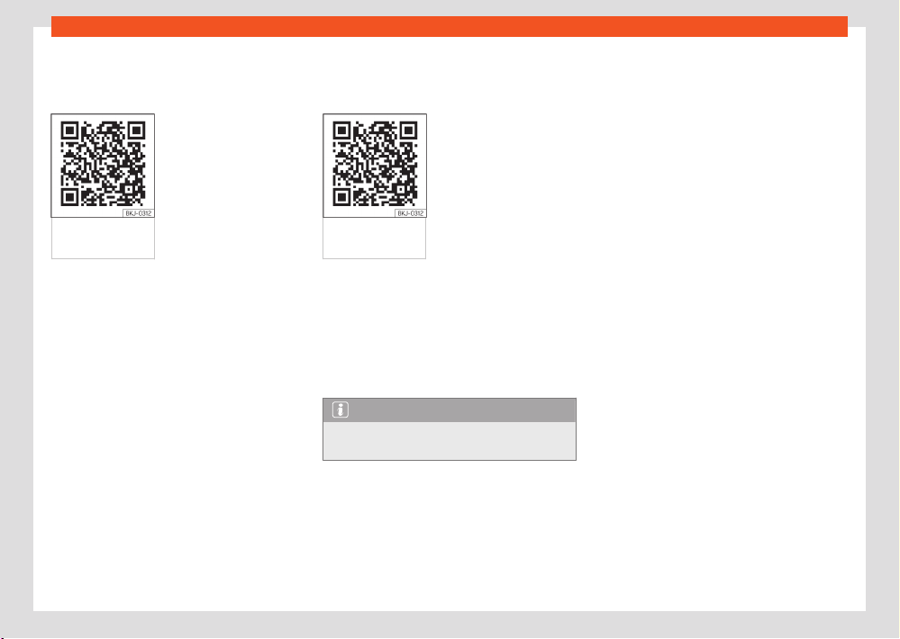
Digital instruction manual
The digit
al version of the manual can be found
on SEAT's ocial website:
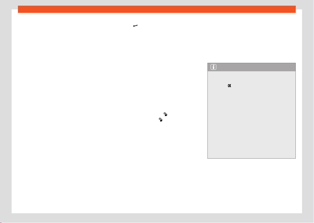
Fig.1 SEAT
w
ebsite
●
scan the QR code.
●
OR ent
er the following address in the naviga-
tor website:
https://www.seat.com/owners/about-my-car/
manuals.html
and select your vehicle.
Related videos
The oper
ation of some of the vehicle's features
can be shown as an instruction video:
Fig.2 SEAT
w
ebsite
●
scan the QR code.
●
OR ent
er the following address in the naviga-
tor website:
https://www.seat.com/owners/about-my-car/
manuals.html
choose your vehicle and then the “Multimedia”
section.
Note
Video instructions are only available in cer-
t
ain languages.
6
General views of the vehicle
General views of the vehicle
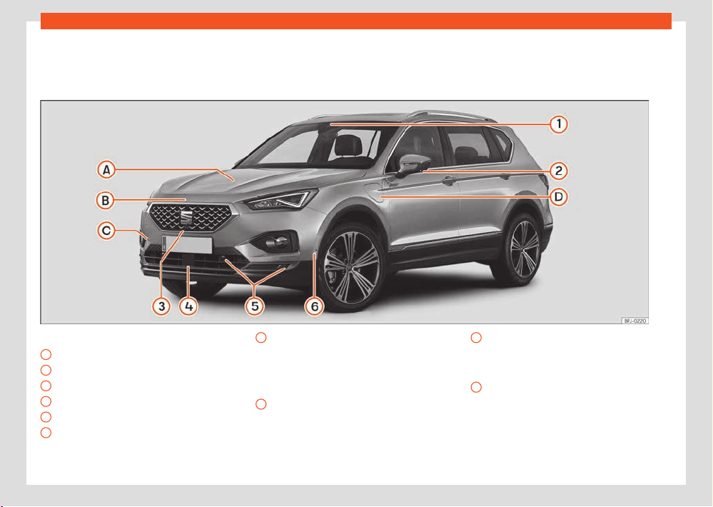
Fr
ont exterior view
Driving assistance sensors ›››page178
1
Front multifunction camera
2
“Top View Camera” mirror cameras
3
“Top View Camera” front camera
4
Front radar
5
Park distance control sensors
6
Park assist sensor
A
Levels control
Oil ›››page337
Brake fluid ›››page335
Battery ›››page341
B
Bonnet
Unl
ocking lever ›››page331
Open/close ›››page331
C
Towing the vehicle
Tow start ›››page321
Towline anchorage ›››page323
D
Charging socket (hybrid v
ehicles)
Charging process display ›››page74
Emergency unlocking ›››page76
General views of the vehicle
7
Rear exterior view
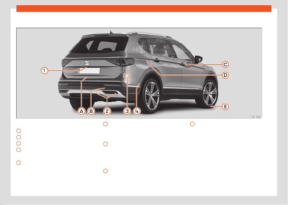
Rear exterior view
Driving assistance sensors ›››page1
78
1
Rear view camera
2
Park distance control sensors
3
Rear radars
4
Park assist sensor
A
Rear lid
Opening from outside ›››page95
Emergency opening ›››page98
B
Towing the vehicle
T
ow-start ›››page321
Towline anchorage ›››page323
C
Opening and closing
Doors ›››page92
Centr
al locking ›››page87
Emergency lock ›››page93
D
Fuel tank
Fuel capacit
y ›››page382
Open/Close cap ›››page309
E
Action in the event of a puncture
Anti-punct
ure kit ›››page360
Wheel change ›››page353
8
General views of the vehicle
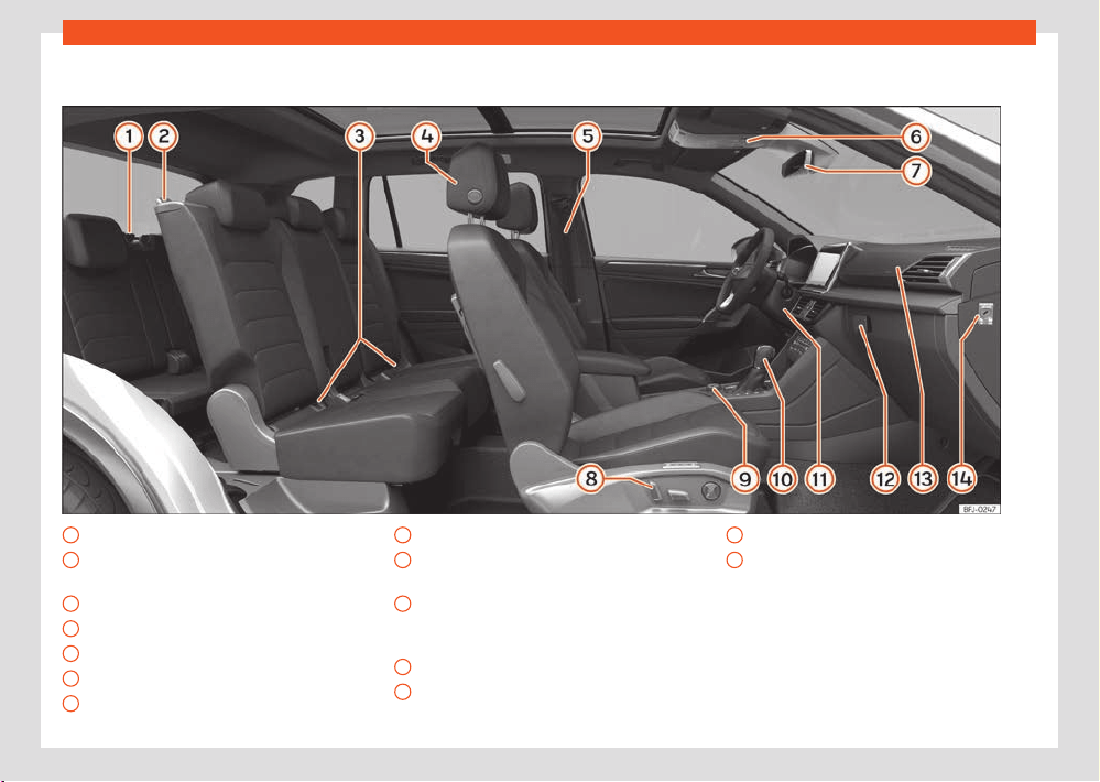
Interior view
1
Folding the third row of seats ›››page288
2
Access to the third row of seats
›››page1
16
3
Isofix anchors ›››page58
4
Headrest adjustment ›››page1
11
5
Seat belts ›››page42
6
Sunroof ›››page101
7
Interior mirror ›››page128
8
Seat adjustment ›››page107
9
Rotary Driving Experience Button
›››page1
71
10
DSG automatic transmission
›››page161 / Manual gearbo
x
›››page160
11
Emergency start ›››page154
12
Glove compartment ›››page236
13
Front passenger airbag ›››page51
14
Disconnecting the front passenger front
airbag ›››page52
General views of the vehicle
9
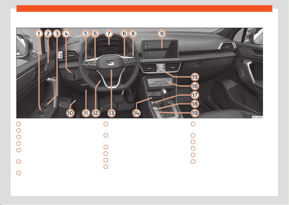
Overview (left hand drive)
Overview (left hand drive)
1
Electric windows ›››page98
2
Central locking ›››page86
3
Exterior mirror adjustment ›››page129
4
Lighting control ›››page1
18
5
Turn signal and main beam lever
›››page120
6
Multifunction steering wheel control panels
›››page105
7
SEAT Digital Cockpit ›››page16
Contr
ol lamps ›››page11
8
Wipers and rear window wiper
›››page125
9
Infotainment system ›››page33,
›››page254
10
Open bonnet lever ›››page331
11
Fuses ›››page32
4
12
Steering wheel adjustment ›››page106
13
Steering wheel with driver’s airbag
›››page51 / Gear shift paddl
es for the
Tiptronic ›››page163
14
Connectivity Box / Wireless Charger
›››page284
15
Hazard warning lights ›››page65
16
Air conditioning ›››page133
17
Start button ›››page150
18
Electronic parking brake ›››page207
19
Auto Hold ›››page208
10
General views of the vehicle
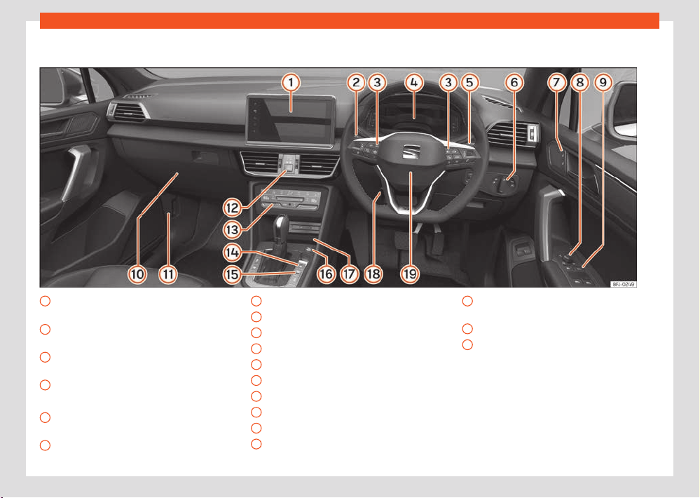
Overview (right hand drive)
1
Infotainment system ›››page33,
›››page254
2
Turn signal and main beam lever
›››page120
3
Multifunction steering wheel control panels
›››page105
4
SEAT Digital Cockpit ›››page16
Contr
ol lamps ›››page11
5
Wipers and rear window wiper
›››page125
6
Lighting control ›››page1
18
7
Central locking ›››page86
8
Exterior mirror adjustment ›››page129
9
Electric windows ›››page98
10
Fuses ›››page32
4
11
Open bonnet lever ›››page331
12
Hazard warning lights ›››page65
13
Air conditioning ›››page133
14
Electronic parking brake ›››page207
15
Auto Hold ›››page208
16
Start button ›››page150
17
Connectivity Box / Wireless Charger
›››page284
18
Steering wheel adjustment ›››page106
19
Steering wheel with driver’s airbag
›››page51 / Gear shift paddl
es for the
Tiptronic ›››page163
Driver information
11
Control lamps
Driver information
Contr
ol lamps
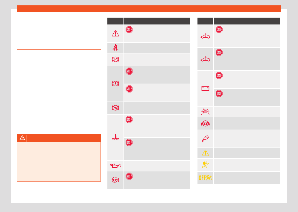
Control and warning lamps
The warning and control lights can be lit indi-
vidually or in combination and serve as a warn-
ing, to indicate the presence of an anomaly or
to warn of the activation of certain functions.
Some turn on when the ignition is switched on
and have to be switched o after a certain pe-
riod of time.
Depending on the model, additional text mes-
sages may be viewed on the instrument panel
display. These may be purely informative or
they may be advising of the need for action.
Depending upon the equipment fitted in the
vehicle, instead of a warning lamp, sometimes
a symbol may be displayed on the instrument
panel.
WARNING
If the warning lamps and messages are ig-
nor
ed, faults may occur in the vehicle, it may
stall in trac, or accidents and serious inju-
ries may occur.
●
Never ignore warning lamps or text mes-
sages.
●
Stop the vehicle safely as soon as possible.
Symbol Meaning
Stop driving!
Centr
al warning lamp ›››page25
Fasten your seat belt ›››page4
2
Electronic parking brake on
›››page207
Stop driving!
F
ault in the brake system ›››page173
Stop driving
Br
ake fluid level low ›››page336
Take control of the vehicle and be ready
t
o brake! ›››page186
Stop driving!
F
ault in the motor coolant system
›››page20
Stop driving!
F
ault in the high-voltage system coolant
fluid system ›››page20
Engine oil pressure ›››page340
Stop driving!
St
eering anomaly ›››page169
Symbol Meaning
Stop driving!
F
ault in the high voltage system
›››page75
Stop driving!
F
ault in the electric drive system
›››page156
Stop driving!
12 v
olt battery ›››page344
Stop driving!
Alt
ernator fault ›››page344
Collision warning ›››page194
Take control of the steering immediately
›››page201
AdBlue level® too low, OR f
ault in
the SCR system ›››page313,
›››page313
Central warning lamp ›››page25
Fault in the airbag system or the seat
belt t
ensioners ›››page51
Front passenger front airbag o
›››page51
12
Driver information
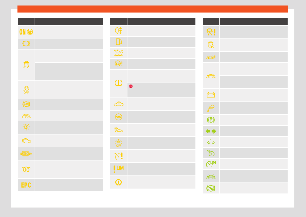
Symbol Meaning
Front passenger airbag on
›››page51
Please check brake pad ›››page1
74
Lights up: f
ault in the electronic stability
control (ESC) ›››page176
Flashing: Electronic stability control
(ESC) or Traction Control regulating
›››page176
TCS manually deactivated, ESC in
“Sport” mode or ECS manually deacti-
v
ated ›››page175
ABS fault ›››page1
76
Travel assist unavailable ›››page200
Fault in the vehicle's lighting
›››page1
18
Fault in the emissions control system
›››page315
Particulate filt
er clogged
›››page315
Diesel engine preheating; OR
diesel engine management f
ault
›››page315
Petrol engine management fault
›››page315
Symbol Meaning
Rear fog light on ›››page1
18
Fuel tank almost empty ›››page19
Engine oil level ›››page341
Steering anomaly ›››page1
70
Fault in the tyre pressure loss indicator
›››page360
¡Stop driving!
L
ow tyre pressure ›››page360
Fault in the electric drive system
›››page156
Electric drive system power limits
›››page156
Electronic engine sound fault
›››page156
Collision warning deactivated
›››page195
Cruise control fault (GRA)
›››page184
Speed limiter not available
›››page185
Gearbox fault ›››page16
7,
›››page167
Symbol Meaning
Adaptive cruise control (ACC) not avail-
abl
e ›››page190
Emergency Assist unavailable
›››page202
Lane Assist not available ›››page198
Emergency Assist regulating
›››page201
Lane Assist (lane keeping system) regu-
l
ating ›››page197
Battery / 12V power supply
›››page344
AdBlue level® low, OR f
ault in the SCR
system ›››page313, ›››page313
Auto Hold activated ›››page208
Turn signals ›››page1
18
Trailer turn signals ›››page1
18
Cruise control (GRA) ›››page182
Speed limiter active ›››page184
Lane Assist (lane keeping system) ac-
tiv
e. ›››page197
Press the brake pedal ›››page16
7
Driver information
13
Instrument panel
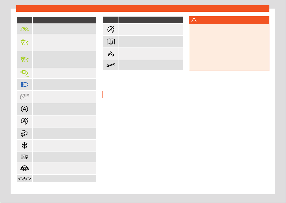
Symbol Meaning
Travel Assist active ›››page199
Adaptive Cruise Control (ACC) reg-
ul
ating, no vehicle detected ahead
›››page187
Adaptive Cruise Control (ACC) reg-
ul
ating, vehicle detected ahead
›››page187
Vehicle charging ›››page7
4
Main beam on or flasher on
›››page1
18
The speed limiter is not active
›››page184
Start-Stop system activated
›››page158
Start-Stop system unavailable
›››page158
Hill descent control (HDC)
›››page168
Exterior temperature below +4°C
(+39°F) ›››page22
Main beam assist active ›››page12
1
Take control of the steering
›››page200
Distance warning ›››page193
Symbol Meaning
Electric mode driving not available
›››page158
Reference to information in the on-
boar
d documentation ›››page25
Remove foot from accelerator
›››page29
Service intervals display ›››page31
Instrument panel
Intr
oduction
After switching the engine on with a 12-volt
battery that is heavily discharged or newly
changed some system settings (such as the
time, the date, the personalised comfort set-
tings and the programming) might be altered or
deleted. Check and correct these settings once
the battery is suciently charged.
WARNING
Any distraction may lead to an accident, with
the risk of injury.
●
Do not operate the instrument panel con-
tr
ols when driving.
●
To reduce the risk of accident and injury,
only make adjustments to the instructions
on the instrument panel display and to the
instructions on the Infotainment system dis-
play when the vehicle is stationary.
14
Driver information
1)
Not available for PHEV hybrid vehicles.
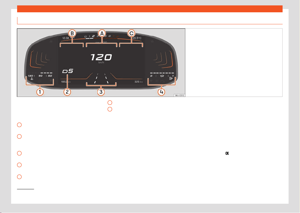
Basic version digital instrument cluster
Fig.3 Basic v
ersion digital instrument cluster: Main
view.
Upper zone: T
ime, selected driving profile, rev
counter, outside temperature. Lower zone: total
km (miles) or speed set with the cruise control
or ACC, range.
A
Main display: speed in digit
al format and
road signs.
B
Secondary indications: driving dat
a
(average speed and fuel consumption, dis-
tance travelled, etc.)
C
Secondary indications: r
adio, media,
phone, navigation indications.
1
Engine coolant temperature indicator
›››page20.
2
Gear engaged and gear or selector lever
position recommendation.
3
Selected driving assistant.
4
Fuel gauge ›››page18.
The Basic
1)
v
ersion digital instrument cluster is a
digital instrument cluster with a high resolution
colour TFT display.
Other content can be displayed by selecting
dierent views, e.g. Rev counter, and dierent
displays in the main display area and in the
secondary display areas.
Instrument cluster operation
The digit
al instrument cluster can only be con-
trolled from the buttons on the multi-function
steering wheel. The functions of the buttons on
the multifunction steering wheel depend on the
equipment.
As long as a priority 1 warning is active, it will not
be possible to access any menu ›››page25.
Some warnings can be confirmed and hidden
with the button
of the multifunction steering
wheel.
Driver information
15
Instrument panel
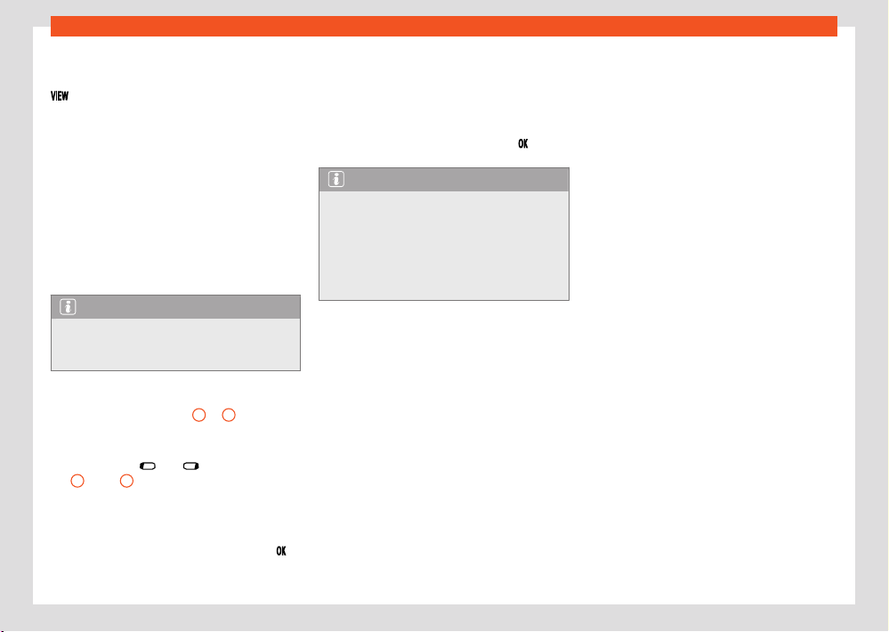
Instrument cluster views
T
o switch between the dierent views press the
button on the multifunction steering wheel.
The f
ollowing views can be displayed:
●
Main: Digital speedometer with secondary
indications.
●
Speed: Classic representation of the speed-
ometer as a circular instrument with secondary
indications in the centre of the dial.
●
Rev counter: Classic representation of the rev
counter as a circular instrument with secondary
indications in the centre of the dial.
The amount and content of the information dis-
played may vary depending on the equipment.
Note
After switching o the ignition, a displ
ay
appears showing vehicle status information,
such as distance travelled.
Select secondary indications in the “Main” view
The secondary indications
B
or
C
can be in-
dividually configur
ed or hidden. Proceed as fol-
lows to select the secondary indications:
1. Use the keys
and to select the right
B
or left
C
secondary indications area.
2. Use the thumbwheel on the multifunction
st
eering wheel to select the desired secon-
dary indication.
3. Confirm your selection by pressing the
button.
Selecting secondary indications in the “Speed”
or “R
ev counter” views
1. Use the thumbwheel on the multifunction
steering wheel to select the desired secon-
dary indication.
2. Confirm the selection by pressing
.
Note
If when switching on the ignition warnings
ar
e shown about existing faults, it might not
be possible to change the settings or show
the information as described. If the fault
continues, visit a duly qualified specialised
workshop. SEAT recommends visiting a SEAT
dealership.
16
Driver information
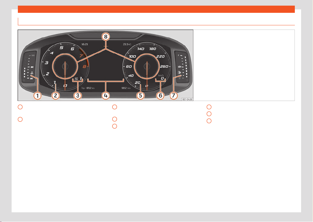
SEAT Digital Cockpit
Fig.4 SEAT Digit
al Cockpit on the instrument
panel (classic view).
1
Engine coolant temperature display
›››page20
2
Revolution counter. R
evolutions per mi-
nute the engine is running›››page18.
3
Gear engaged or position of the selec-
t
or lever.
4
Screen display ›››page2
1.
5
Speedometer
6
Digital speed display
7
Fuel gauge ›››page18.
8
Information Pr
ofile ›››page17.
Driver information
17
Instrument panel
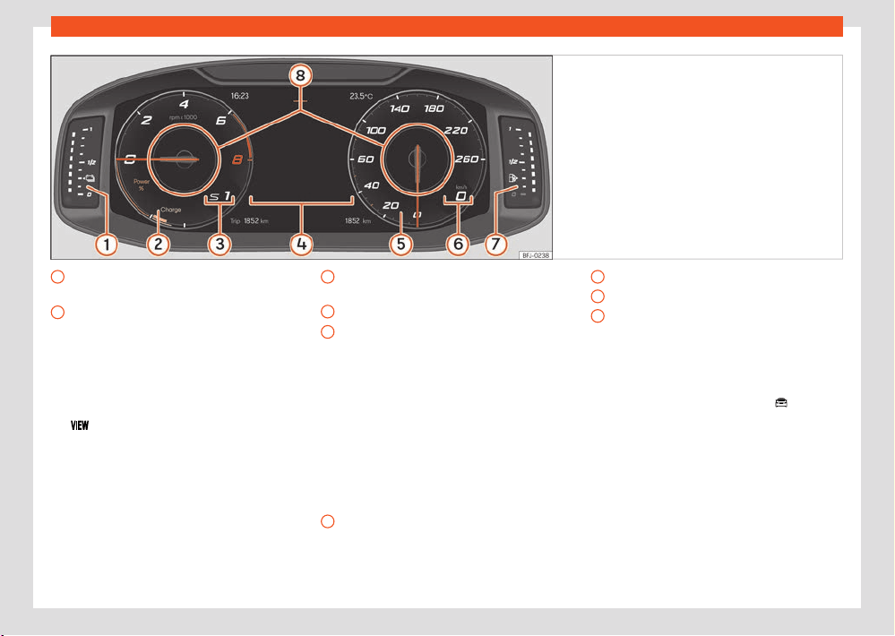
Fig.5 Hybrid v
ehicles: SEAT Digital Cockpit on the
instrument panel (classic view).
1
Battery charge level indicator
›››page19
2
Rev counter and Powermeter. R
evolu-
tions per minute the engine is running
›››page21.
3
Gear engaged or position of the selec-
t
or lever
4
Screen displays ›››page2
1.
5
Screen display ›››page2
1.
6
Speedometer
7
Digital speed display
8
Fuel gauge ›››page18.
The SEAT Digital Cockpit is a digital instrument
clust
er with a high resolution colour TFT dis-
play. It has a 3 views accessible using the but-
ton
of the multifunction steering wheel. By
sel
ecting dierent information profiles, indica-
tions other than the classic circular instruments
can be displayed, such as navigation data,
multimedia information or travel data.
The 3 views are:
●
Classic
●
Dynamic
●
Navigation
All views will display information on the screen
about audio, phone, travel data, vehicle status,
navigation and driving aids.
In all views the information displayed in Infor-
mation profiles can be customised ›››Fig.4
8
.
Information pr
ofiles
Use the infotainment system menu
> Se-
lection > Digital Cockpit t
o choose be-
tween the dierent options for viewing informa-
tion to be displayed in the SEAT Digital Cockpit.
Classic View
The revolutions per minute and speedome-
ter needles appear along the entire length
›››Fig.4.
18
Driver information
1)
Pre-set information depending on the selected “Driving mode”.
View 1, 2, 3 or AUTOMATIC
1)
P
ersonalisation of the information that appears
in the SEAT Digital Cockpit. Only 2 of these
items of information can be displayed at the
same time, but the user chooses which to dis-
play, and in what order, by moving the finger
vertically over the dials.
Depending on the version, the Views can be
memorised by exiting the menu or keeping the
View button pressed.
●
Consumption. Gr
aphic representation of the
current consumption and digital display of the
average consumption.
●
Audio. Digital display of the current audio
playback.
●
Altitude. Digital display of the current altitude
above sea level.
●
Compass. Digital display of the compass.
●
Destination arrival information. Digital dis-
play of the remaining travelling time, distance
to the destination and the estimated time of
arrival.
●
Range. Digital display of the remaining range.
●
Travelling time.
●
Route guidance.
●
Journey. Digital display of the distance trav-
elled.
●
Assist systems. Graphic representation of
dierent assistance systems.
●
Road signs. Displ
ay of trac signs detected.
●
Navigation. Graphical representation of the
navigation with arrows.
It may vary based on the features, the number
and the contents of the selectable information
profiles.
Revolution counter
The rev counter indicates the number of engine
revolutions per minute.
Together with the gear-change indicator, the
rev counter oers you the possibility of using
the engine of your vehicle at a suitable speed.
The beginning of the red zone of the rev counter
indicates the maximum speed in any gear after
running-in and with the engine hot. However,
it is advisable to move the selector lever to D
or lift your foot o the accelerator before the
needle reaches the red zone ›››
.
W
e recommend that you avoid high revs and
that you follow the recommendations on the
gear-change indicator. See the additional infor-
mation in ›››page145, Selecting the optimal
gear.
NOTICE
●
To prevent damage to the engine, the rev
count
er needle should only remain in the red
zone for a short period of time.
●
When the engine is cold, avoid high revs
and heavy acceleration and do not make the
engine work hard.
For the sake of the environment
Changing up a gear early will help you to
sav
e fuel and minimise emissions and engine
noise.
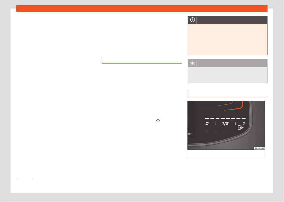
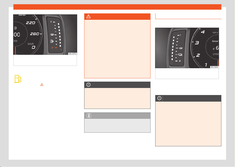
Fuel gauge
Fig.6 Basic instrument clust
er: fuel gauge.
Driver information
19
Instrument panel
Fig.7 SEAT Digit
al Cockpit instrument cluster:
fuel gauge.
Control lamps
Its lights up yellow. Fuel tank almost
empt
y. The fuel reserve level has been
reached ›››
. Refuel as soon as you
hav
e the opportunity.
When the fuel level is very low, the lower
diode also flashes red.
The display only works when the ignition is
switched on.
The fuel range is displayed on the instrument
panel.
You can consult the tank capacity of your vehi-
cle in ›››page382.
WARNING
When driving with low fuel, the vehicle may
st
all in trac and cause accidents and se-
vere injuries.
●
If the fuel tank level is too low, fuel could
reach the engine irregularly, particularly
when driving up or down slopes.
●
The steering system and the assistant sys-
tems and brakes do not work when the en-
gine is running irregularly or switches o due
to lack of fuel or an irregular supply thereof.
●
SEAT recommends always refuelling when
the tank is approximately one quarter full, to
prevent the vehicle from stopping due to a
lack of fuel.
NOTICE
Never run the fuel tank completely dry. An
irr
egular fuel supply can cause misfiring and
unburnt fuel could enter the exhaust system.
The catalytic converter or the particulate fil-
ter may get damaged!
Note
The small arrow on the fuel gauge next to the
fuel pump symbol points out towards the side
of the vehicle with the fuel tank flap.
Battery level indicator
✓ V
alid for: hybrid vehicles
Fig.8 Instrument clust
er: battery level
indicator.
The small arrow next to the battery symbol on
the fuel gauge indicat
es which side of the vehi-
cle the charging cover is on.
NOTICE
●
Never drive with the tank completely
empt
y. Under certain circumstances, the en-
ergy stored in the high-voltage battery may
not be sucient to reach the nearest service
station.
●
When the outside temperature is very
low, and therefore the high-voltage battery
is very cold, diculties may arise in start-
ing the internal combustion engine and the
range in the electric driving mode may be
reduced.
20
Driver information
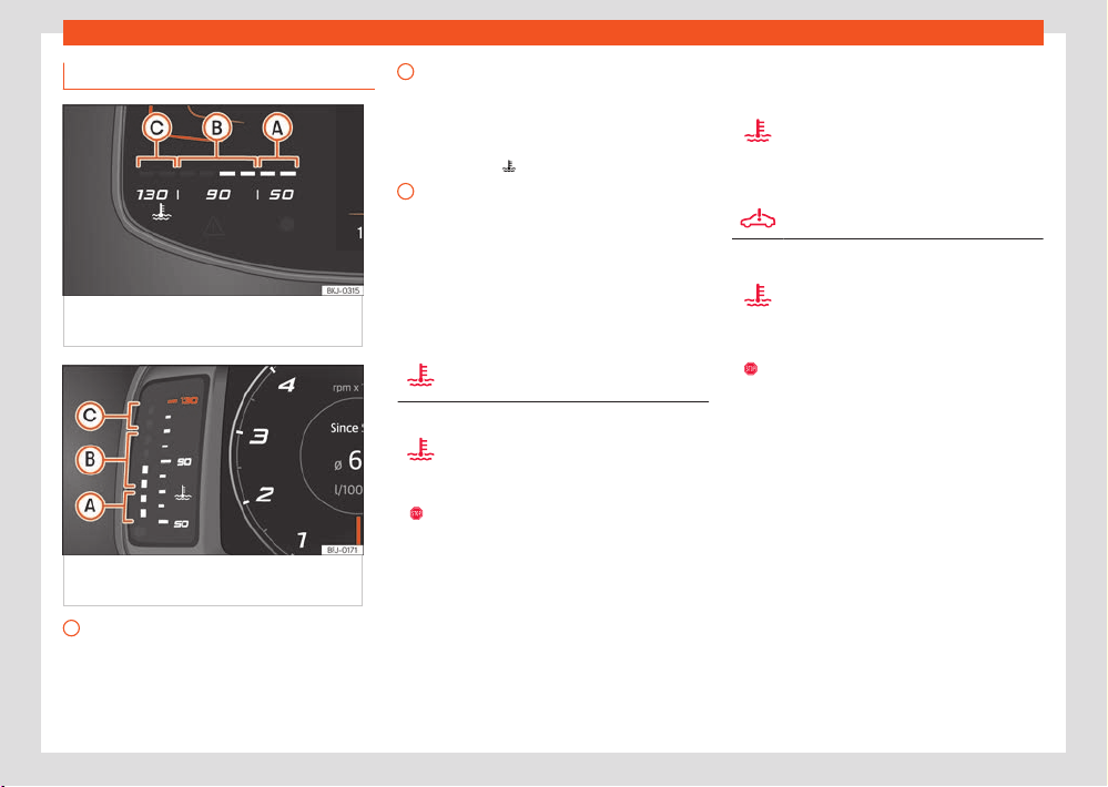
A
B
C
Coolant temperature indicator.
Fig.9 Basic digit
al instrument cluster: engine
coolant temperature display.
Fig.10 SEAT Digit
al Cockpit digital instrument
cluster: engine coolant temperature indicator.
Cold zone. The engine has not r
eached
operating temperature yet. Avoid high en-
gine speeds and stressing the engine if it
has not reached operating temperature.
Normal zone. At high outside t
emperatures
and when making the engine work hard,
the diodes may continue lighting up and
reach the upper zone. This is no cause for
concern, provided the control lamp does
not light up
.
W
arning area. When the engine is working
hard, especially at high outside tempera-
tures, the diodes may light up in the warn-
ing area.
The coolant temperature gauge only works
when the ignition is switched on.
Control and warning lamps
Fault in the engine coolant system
The LED flashes r
ed.
Engine coolant
The l
amp lights up red.
The motor coolant temperature is too high
or the motor coolant level is too low.
●
St
op driving! Stop the vehicle at the next
opportunity and in a safe place.
●
Switch o the engine and let it cool down.
●
Check the coolant level in the coolant expan-
sion tank ›››page334.
If the warning lamp does not go out even
though the motor coolant level is correct, do
not continue to drive or leave the motor running.
Seek specialist assistance.
Control and warning lamps (valid for hybrid
vehicles)
to-
gether
with
Fault in the high-voltage cooling
cir
cuit
The warning lamps flash red.
Engine coolant
The l
amp lights up red.
Engine or high-voltage system coolant
level too low, engine or high-voltage sys-
tem coolant temperature too high.
●
St
op driving! Stop the vehicle at the next
opportunity and in a safe place.
●
Switch o the engine and let it cool down.
●
Check the coolant level in the coolant expan-
sion tank ›››page334.
●
Check the coolant level in the high-voltage
cooling circuit ›››page333. If the level is too
low DO NOT add coolant. Seek specialist as-
sistance immediately.
If the warning lamp does not go out even
though the motor coolant level is correct, do
not continue to drive or leave the motor running.
Seek specialist assistance.
Driver information
21
Instrument panel
Green
Blue
A
B
C
NOTICE
●
To ensure a long useful life for the engine,
av
oid high revs, driving at high speed and
making the engine work hard for approxi-
mately the first 15 minutes when the engine
is cold. The phase until the engine is warm
also depends on the outside temperature. If
necessary, use the engine oil temperature as
a guide ›››page23.
●
Additional lights and other accessories in
front of the air inlet reduce the cooling eect
of the coolant. At high outside temperatures
and high engine loads, there is a risk of the
engine overheating.
●
The front spoiler also ensures proper distri-
bution of the cooling air when the vehicle is
moving. If the spoiler is damaged this can
reduce the cooling eect, which could cause
the engine to overheat. Seek specialist assis-
tance.
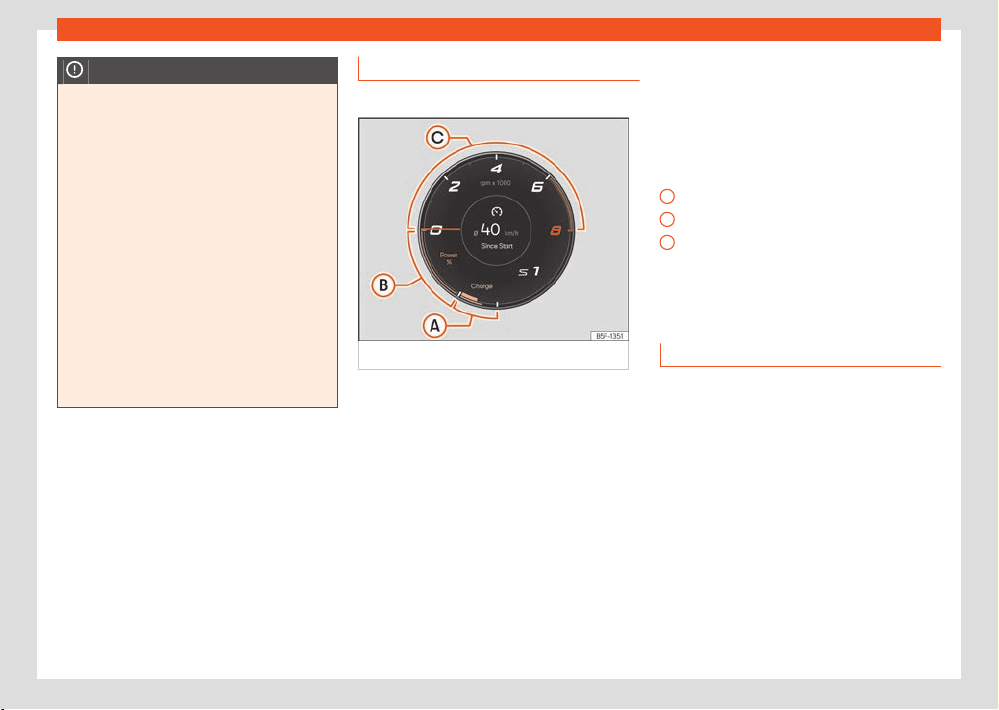
Power meter
✓ Valid for: hybrid vehicles
Fig.11 Digit
al instrument cluster: Power meter
The lower left hand side of the rev counter has
tw
o colour coded areas:
Charge: Energy recovery zone.
Power %: Electric traction zone. Indicates
the percentage of power used and the
maximum amount of power currently avail-
able.
The power meter shows the usage level of the
electric drive. The power meter bar shows the
current usage level.
A finer col
oured border indicates how much the
propulsion can currently be used. Depending
on the selected driving program and the cur-
rent availability of electrical power, the boun-
daries of the dierent colours can vary.
The following displays can be seen on the
Power meter: ›››Fig.11,.
The vehicle recovers electrical energy.
e-Mode electric driving.
The combustion engine must be running.
With the Boost function, the vehicle drives
for a short period of time with maximum
power from both the electric motor and the
combustion engine.
Status display
Possible indications on the instrument panel
display
The instrument cluster can display a variety of
information, superimposed according to the ve-
hicle's equipment:
●
Doors, bonnet and rear lid open
●
Warning and information messages
●
Odometer
●
Time ›››page30
●
Indications of the radio and navigation sys-
t
em
●
Indications of the phone
●
Outside temperature

22
Driver information
1)
Valid for the basic digital instrument cluster.
●
Compass indication
●
Selector lever positions
●
Gear-change recommendation
●
Combined range (hybrid vehicles)
●
Display of travel data (multifunction display)
and menus f
or dierent settings ›››page23
●
Service interval display ›››page30
●
Speed warning
●
Speed warning for winter tyres
●
Start-Stop system status display
›››page158
●
Signs detected by the trac signal detection
system ›››page27
●
Indication of active cylinder management
st
atus (ACT®) ›››page145
●
Low consumption driving
●
Assistant systems display
●
Personalization: greeting ›››page2
42
●
Engine oil temperature
●
Indication of radiator fan operation with en-
gine stopped
1)
Doors, bonnet and rear lid open
When the vehicle is unlocked and while driving,
the instrument panel display shows if any of the
doors, the bonnet or rear lid are opened and, in
some cases, it is also indicated by an audible
warning.
Selector lever positions
The curr
ent position of the selector lever is
shown on the side of the lever and on the in-
strument panel display. When the lever is in the
D/S position or in the Tiptronic position, in some
cases, the gear engaged in each case is shown
on the instrument panel display .
Outside temperature indicator
If the outside temperature is lower than approxi-
mately +4°C (+39°F), the “ice crystal symbol”
also lights up
. This symbol remains lit until
the outside t
emperature exceeds +6°C (+43°F)
›››
.
In the f
ollowing situations, the displayed exte-
rior temperature may be higher than the actual
temperature due to the heat emitted by the
motor:
●
When the vehicle is stationary.
●
When driving very slowly.
Gear-change recommendation
While driving, the instrument panel of certain
vehicles may indicate a gear recommendation
for saving fuel ›››page145.
Odometer
The odometer records the total distance travel-
led by the vehicle.
The partial odometer (trip) shows the dis-
tance travelled since the last time it was reset
to zero.
●
Set the odometer to zero via the Infotainment
syst
em or the multifunction steering wheel
›››page23.
Combined operating range display
(hy-
brid v
ehicles)
The value shown is calculated and updated ac-
cording to the driving style. Therefore, the range
can vary even when the fuel tank is full and the
high-voltage battery is fully charged.
Range can be increased by reducing or switch-
ing o comfort consumers, e.g. air conditioning
or seat heating.
Speed warning for winter tyres
If the maximum set speed is exceeded, this is
displayed on the instrument cluster display.
The speed warning can be set in the infotain-
ment system (
> Settings > Tyres;
OR > Exterior settings > Tyres)
›››page36.
Compass indication
Depending on the equipment, when the ignition
is on, the instrument panel displ
ay indicates the
direction in which you are driving with a symbol,
e.g. NW for Northwest.
Driver information
23
Instrument panel
1)
Valid for the basic digital instrument cluster.
When the Infotainment system is on and there is
no r
oute guidance active, the graphic represen-
tation of a compass is also shown.
Low consumption driving
Depending on the equipment, when driving, the
display appears on the instrument panel
when the v
ehicle is in low consumption status
due to active cylinder management (ACT®)
›››page145.
Radiator fan operation indication
1)
This indication is displayed after switching o
the ignition when the radiator fan is still running.
The operating time of the radiator fan can de-
pend on:
●
Exhaust gas treatment, e.g. during regenera-
tion of the particul
ate filter.
●
Active brake cooling after descending a
slope.
●
Dissipation of heat from the engine after high
stress, e.g. after a very long drive.
Destination information
1)
If route guidance is enabled, the expected
travel time and the distance to the destination
are displayed.
Navigation indications
1)
If route guidance is activated, the direction of
travel is shown by arrows.
WARNING
Even when the outside temperature is higher
than fr
eezing temperature, some roads and
bridges could be frozen.
●
The “ice crystal symbol” indicates that
there may be a risk of freezing.
●
At outside temperatures above +4°C
(+39°F), there may be ice even when the “ice
crystal symbol” is not on.
●
The outside temperature sensor takes a
guideline measurement.
Note
●
There are dierent instrument panels and
therefore the versions and instructions on
the display may vary. In the case of dis-
plays without warning or information texts,
faults are indicated exclusively by the con-
trol warning lamps.
●
Some settings can be saved in the user ac-
counts of the personalization function and
can therefore be changed automatically
when switching user accounts ›››page242.
●
Some indications on the instrument panel
scr
een may be concealed by a sudden
event, e.g. an incoming call.
●
Depending on the equipment, some set-
tings and instructions can be carried out
or displayed on the infotainment system as
well.
●
If there are several warnings at the same
time, the symbols will be displayed one after
the other for a few seconds. The symbols will
stay on until you remove the cause.
●
If when switching on the ignition warnings
are shown about existing faults, it might not
be possible to change the settings or show
the information as described. In this case, go
to a specialised workshop and request a re-
pair.
Driving data indicator
The driving data display shows a range of driv-
ing data and consumption values.
Change from one display to another
●
Turn the right thumbwheel of the multifunc-
tion steering wheel ›››page32.

24
Driver information
1)
This will show all data on the display at the same time: distance travelled, average consumption, average speed and autonomy.
2)
Valid for the SEAT Digital Cockpit.
3)
Not available in all countries.
–
–
–
–
–
–
–
–
–
–
–
–
–
Changing memory
●
While in Driving data > General in-
formation pr
ess
on the multi-function
st
eering wheel to switch between the 3 memo-
ries
1)
:
Since start: The memory is del
eted if
the journey is interrupted for more than 2
hours.
Since refuel: Display and storage of
the journey data and the consumption val-
ues collected. When refuelling, the memory
is deleted.
Long-term: This memory contains travel
data up to a maximum of 19hours and
59 minutes or 99 hours and 59 minutes, or
up to a maximum of 1999.9 km or 9999.9
km. When one of these values is exceeded
(varies depending on the version of the in-
strument panel), the memory is deleted.
Delete journey data presets
●
Select the memory that you wish to erase.
●
Keep the
button on the multi-function
st
eering wheel pressed for approximately 2
seconds.
Select the instructions
In the Inf
otainment system, in the menu Vehicle
settings, you can display dierent travel data
›››page37.
Current consumption: The current fuel
consumption display operates throughout
the journey, in litres/100 km; and with the
engine running and the vehicle stopped, in
litres/hour.
Average consumption: The average
fuel consumption is displayed after driving
for approximately 300 metres.
Travelling time: This indicates the
hours (h) and minutes (min) since the igni-
tion was switched on.
Range:
2)
Approximate distance in km that
can still be travelled if the same driving
style is maintained.
AdBlue range or
: Appr
oximate dis-
tance in km that can still be travelled with
the current level of the AdBlue® tank with
the same driving style. The indication ap-
pears from a range of less than 2400 km
and cannot be deactivated.
3)
Distance travelled: Distance covered
in km (m) after switching on the ignition.
Average speed: The av
erage speed will
be shown after driving for approximately
100 metres.
Digital speed: Current speed dis-
played in digital format.
Eco tips: Recommendations messages
are shown to reduce consumption through
good driving practices, e.g. Air condi-
tioning on: close the window.
Boost/Torque: Indicates the power and
torque of the combustion engine (does not
indicate electric mode).
Setting a speed warning
●
Select the display Warning at ---km/h or
W
arning at ---mph.
●
Press the
button on the multi-function
st
eering wheel to memorise the current speed
and activate the warning.
●
Activate: set the desired speed within 5 sec-
onds by rotating the wheel on the multi-func-
tion steering wheel. Next, press the
button
again or w
ait for a few seconds. The speed is
stored and the warning activated.
●
Deactivate: press the
button. The stored
speed is del
eted. The warning can be set for
speeds of between 30 and 250km/h (18 and
155mph).
Driver information
25
Instrument panel
Oil temperature display
The engine r
eaches its operating temperature
when, under normal driving conditions, the
oil temperature is between 80°C (176°F) and
120°C (248°F). If a great eort is required from
the engine and the outside temperature is high,
the engine oil temperature may increase. This
does not present any problem as long as the
warning lamps
or ›››page340 do not
appear on the displ
ay.
Warning and information messages
The system runs a check on certain com-
ponents and functions when the ignition is
switched on and while the vehicle is moving.
Faults are displayed on the instrument cluster
display as red and yellow warning symbols
›››page11 accompanied by messages and,
depending on the case, even an audible warn-
ing. The representation of the messages and
symbols may vary depending on the version of
the instrument panel.
Existing faults can also be checked man-
ually. To do this, open the Vehicle status
›››page32 menu.
Priority 1 warning (in red)
The symbol lights up or flashes (in part ac-
companied by audibl
e warnings).
St
op driv-
ing! Danger! Check the fault and eliminate
the cause. If necessary, seek professional assis-
tance.
Priority 2 warning (in yellow)
The symbol lights up or flashes (in part accom-
panied by audibl
e warnings). Operating faults
or the lack of operating fluids can cause dam-
age to the vehicle or a fault. Check the faulty
function as soon as possible. If necessary, seek
professional assistance.
Reference to information in the owner's
manual
Further inf
ormation on any warnings can be
found in the owner's manual.
Information message
It provides information about processes in the
vehicle.
Driver alert system (break recom-
mendation)
Fig.12 On the scr
een of the instrument panel:
fatigue detection.
The driver alert system informs the driver when
it deduces tir
edness due to his/her behaviour at
the wheel.
Function and operation
Fatigue detection determines the driving be-
haviour of the driver when starting a journey,
making a calculation of tiredness. This is con-
stantly compared with the current driving be-
haviour. If the system detects that the driver is
tired, an audible warning is given with a sound
and an optical warning is shown with a sym-
bol and supplementary message on the instru-
ment cluster screen ›››Fig.12. The message
on the instrument panel display is shown for
26
Driver information
approximately 5 seconds, and depending on
the case
, is repeated. The system stores the last
message displayed.
The warning on the instrument cluster display
can be hidden as follows:
●
Press the
button on the multifunction steer-
ing wheel.
The message can be r
ecovered on the instru-
ment cluster display using the multifunction dis-
play ›››page23.
Conditions of operation
Driving behaviour is only calculated on speeds
above about 65 km/h (40 mph) up to around
200 km/h (125 mph).
Activating and deactivating
Fatigue detection can be activated or deacti-
vated in the infotainment system using the func-
tion button
Driver assistance > Fatigue de-
t
ector.
The driver alert system is always switched on
when the ignition is switched on ›››page37.
System limitations
The Fatigue detection has certain limitations in-
herent to the system. The following conditions
can limit the Fatigue detection or prevent it from
functioning.
●
At speeds below 60km/h (40mph).
●
At speeds above 200 km/h (125 mph)
●
When cornering
●
In sections with roadworks.
●
On roads in poor condition
●
In unfavourable weather conditions
●
When a sporty driving style is employed
●
In the event of a serious distraction to the
driver
Fatigue detection will be restored when the ve-
hicle is stopped for more than 15 minutes, when
the ignition is switched o or when the driver
has unbuckled their seat belt and opened the
door.
In the event of slow driving during a long period
of time (below 60km/h, 40mph) the system
automatically re-establishes the tiredness cal-
culation. When driving at a faster speed the
driving behaviour will be recalculated.
WARNING
The smart technology of the driver alert sys-
t
em cannot overcome the limits imposed by
the laws of physics and only works within the
limits of the system. Do not let the comfort
aorded by the Fatigue detection system
tempt you into taking any risks when driving.
Take regular breaks, sucient in length when
making long journeys.
●
The driver always assumes the responsibil-
ity of driving to their full capacity.
●
Never drive if you are tired.
●
The system does not detect the tiredness
of the driv
er in all circumstances. Consult the
information in the section ›››page26, Con-
ditions of operation.
●
In some situations, the system may incor-
r
ectly interpret an intended driving manoeu-
vre as driver tiredness.
●
No warning is given in the event of the ef-
fect called microsleep!
●
Please observe the indications on the in-
strument panel and act as is necessary.
Note
●
Fatigue detection has been developed for
driving on mot
orways and well paved roads
only.
●
If there is a fault in the system, have it
checked by a specialised workshop.
Driver information
27
Instrument panel
Road signs detection system
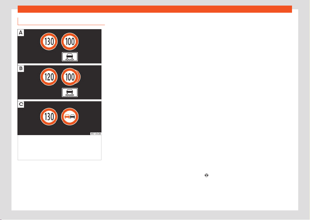
Fig.13 On the instrument panel displ
ay:
examples of speed limits or overtaking
prohibitions with their respective additional
signs.
The dynamic road signs display records stand-
ar
d road signs using a camera fitted to the base
of the interior mirror, and provides information
about speed limits, overtaking prohibitions and
warning signs that it recognises.
Within its limitations, the system also displays
a additional sign t
o indicate aspects such as
temporary prohibitions. Even on routes without
signs, the system can, if necessary, display the
applicable speed limits.
The dynamic road sign display system is acti-
vated whenever the ignition is switched on.
The trac sign detection system does not work
in all countries. Keep this in mind when travel-
ling abroad.
Shown on the display
In Germany, on motorways and vehicle roads,
besides speed limits and overtaking provisions
the system also displays the end of prohibition
signs. The valid speed limit at the time in other
countries is always shown.
The road signs detected by the system are
displayed on the instrument cluster display
›››Fig.13 and, depending on the navigation
system fitted in the vehicle, in the infotainment
system as well .
Road sign detection system messages:
There are no road signs available
●
The system is in its start-up phase.
●
OR: the camera has not recognized any man-
datory or prohibitive signs.
Error: Dynamic road sign display
●
There is a fault in the system. Have the system
checked by a specialised workshop.
Speed warning is currently unavail-
able
●
The speed warning function of the road sign
det
ection system is faulty. Have the system
checked by a specialised workshop.
Dynamic road sign display: Clean
the windscreen!
●
The windscreen is dirty in the camera area
or the camera’s visibility is impaired by weather
conditions. Clean the windscreen.
Dynamic road sign display: Cur-
rently restricted
●
The navigation system is not transmitting
data. Check if the navigation system has upda-
ted maps.
●
OR: the vehicle is in a region not included on
the navigation system's map.
No data available
●
The trac sign detection system does not
work in the current country.
Activate and deactivate the road sign dis-
play on the instrument panel
The permanent trac sign view on the instru-
ment cluster can be switched on or o in the
infotainment system using the function button
Driver assistance > Road sign detection.

28
Driver information
Display of tr
ac signs
After checking and evaluating the information
from the camera, the navigation system and
the current vehicle data, the system displays up
to three current road signs ›››Fig.13
with
their additional signs.
●
First: The sign that is curr
ently valid for the
driver is shown in the left side of the screen For
example, a maximum speed limit of 130 km/h
(100mph) ›››Fig.13
.
●
Second: A sign v
alid only in certain circum-
stances, e.g.100 km/h (60mph) is shown sec-
ond, together with the additional rain sign.
●
Additional sign: Displays the circumstances
(rain, times of day, fog, etc.) under which the
displayed speed limit is in force.
●
Third: Thirdly, a sign prohibiting overtaking
is partially displayed. If there is no conditional
speed limit and overtaking is prohibited, the
latter sign will be displayed in second place
›››Fig.13
.
The w
arning sign display is not available in all
countries and the system may not be able to
detect all existing warning signs.
Speed warning
If the system detects that the permitted speed
is exceeded, it may warn the driver with a
“gong” and visually with a message on the
dash panel display.
The speed warning can be set or deacti-
vated completely in the menu
Driver
assistance > Road sign detection
›››page37. The speed w
arning can be set
to a value of 0, 5 or 10km/h (0, 3 or 5mph)
above the permitted speed.
Trailer mode
In vehicles equipped with a towing bracket de-
vice from the factory and a trailer that is electri-
cally connected to the vehicle, it is possible to
activate or deactivate the display of specific
trac signs for vehicles with trailer, such as
speed limits or overtaking prohibitions.
It can be activated or deactivated in the info-
tainment system using the function button
Driver assistance > Trailer assist
›››page37.
F
or trailer mode, the display of speed limits ap-
plicable to the type of trailer or to the legal pro-
visions can be adjusted. The speed is adjusted
in steps of 10km/h (5 mph) within the range
between 60 and 130 km/h (40 and 80mph). If
it is adjusted to a speed greater than that which
is permitted in the country in question for driving
with a trailer, the system automatically displays
the usual speed limits, e.g. in Germany 80km/h
(50mph).
If the speed warning for the trailer is deactiva-
ted, the system displays the speed limits as if
there were no trailer hitched.
Limited operation
The tr
ac sign detection system has certain
limitations. The following cases may lead the
system to operate with limitations or not at all:
●
In the case of poor visibility, e.g. in snow, rain,
fog or intense mist.
●
In cases of dazzling, e.g. caused by head-on
trac or by the sun.
●
When driving at high speeds.
●
If the camera is covered or dirty.
●
If the trac signs are partially or totally ob-
structed, e.g. by trees, snow, dirt or other vehi-
cles.
●
In the case of trac signs that do not fulfil the
regulations.
●
In the case of damaged or bent trac signs.
●
In the case of variable messages on over-
head or gantry signs (LED-based variable traf-
fic signs or other lighting units).
●
If the maps on the navigation system are not
up-to-date.
●
In the case of adhesives axed to vehicles
that depict trac signs, e.g. speed limits on lor-
ries.
Driver information
29
Instrument panel
WARNING
The technology in the tr
ac sign detection
system cannot change the limits imposed by
the laws of physics and only works within the
system's limits. Do not let the extra conven-
ience aorded by the trac sign detection
system tempt you into taking any risks when
driving. The system is not a replacement for
driver awareness.
●
Adapt your speed and driving style to
suit visibility, weather, road and trac condi-
tions.
●
Poor visibility, darkness, snow, rain and fog
may lead to the system failing to display
trac signs or not displaying them correctly.
●
If the camera's field of vision is dirty, cov-
ered or damaged, system operation may be
impaired.
WARNING
The driving recommendations and tr
ac in-
dications shown on the trac sign detection
system may dier from the actual current
trac situation.
●
The system may not detect or correctly
show all the trac signs.
●
Trac signs and trac regulations have
priority over the recommendations and dis-
plays provided by the system.
Note
To avoid aecting the corr
ect operation of
the system, take the following points into
consideration:
●
Regularly clean the area of vision of the
camera and keep it in a clean state, without
snow or ice.
●
Do not cover the field of vision of the cam-
era.
●
Always replace damaged or worn blades
when required to avoid lines on the camera's
field of vision.
●
Check that the windscreen is not damaged
in the area of the camera's field of vision.
●
The use of outdated maps on the naviga-
tion system may cause the system to show
trac signs incorrectly.
●
In the waypoints mode of the navigation
system, the trac sign detection system is
only partly available.
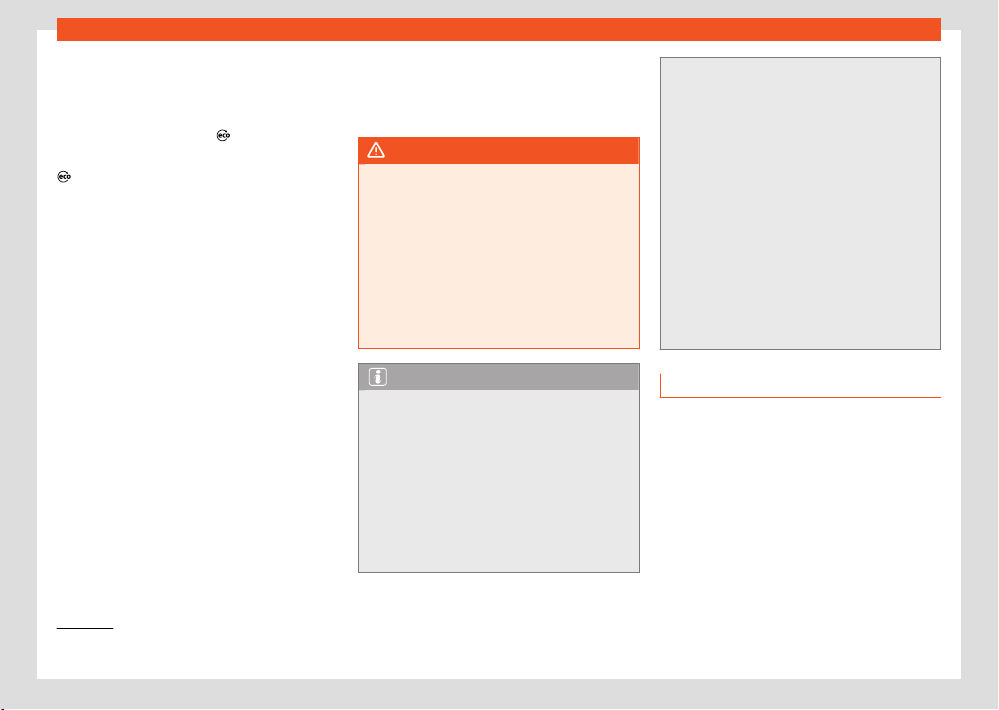
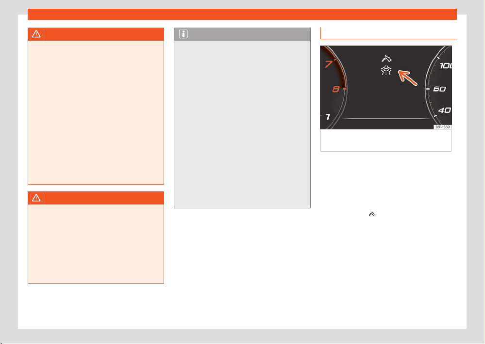
Eco-ecient driving assistance
Fig.14 Eco-ecient driving assist
ance
indication (schematic representation).
Eco-ecient driving assist
ance helps you drive
with care and with low energy consumption by
following instructions superimposed in the digi-
tal cockpit, depending on the situation.
When you approach places such as a junction,
a roundabout or a section of road with a speed
limit, the symbol
is displayed along with an
e
vent in the digital cockpit ›››Fig.14.
As soon as you follow the indication and
take your foot o the accelerator, the vehicle
adapts, based on the selected driving profile
and distance to the incident, brake energy re-
cuperation and speed.
Eco-ecient driving assistance uses the trip
data from the infotainment system and the sen-
sors of some assist systems. If no destination
guidance is active, the most likely route is used.
30
Driver information
Pressing the accelerator can cancel the inter-
v
ention of the assistance at any time.
Eco-ecient driving assistance can be
switched on and o in the infotainment system,
in the assistance system settings ›››page37.
Eco-ecient driving assistance is temporarily
switched o if:
●
The gear selector is in the S position.
●
The Sport driving program is used.
●
Driving with adaptive cruise control (ACC) or
cruise control (GRA).
When these conditions no longer exist, the as-
sistance is reactivated if it is switched on in the
assist system settings.
Eco-ecient driving assistance is available de-
pending on the equipment, although not in all
countries.
WARNING
The system is not a replacement for driver
aw
areness.
●
Adapt your speed and driving style at all
times to suit visibility, weather, road and
trac conditions.
●
Trac signs on the road and trac regula-
tions have priority over eco-driving notes.
Note
●
The appearance of the symbols may vary
slightly depending on the equipment and
model. Syst
em updates may modify or ex-
pand the symbols.
●
When the system is switched on, eco-ef-
ficient driving assistance can also increase
recuperation without any indication being
displayed. This can occur in situations such
as when the accelerator pedal is released
when a vehicle is driving in front. In this case,
energy recuperation is adapted match the
speed of the vehicle in front without any indi-
cation being displayed.
Time and date
Setting the time on the infotainment system
●
Press
> Settings ›››page33.
●
Select the menu option Dat
e and time.
Service Menu
In the Service menu various settings can be ad-
justed depending on the features.
Open the Service menu
Select the Range information profile while in
the Driving data menu, and keep the
key
pr
essed on the multifunction steering wheel for
approximately 4 seconds. When it is released,
the Service menu will be displayed.
Now you can browse through the menu using
the k
eys on the multifunction steering wheel as
usual.
Restart the service interval display
Select the Service menu and follow the in-
structions on the screen of the instrument
panel.
Restart the oil service
Select the Reset Oil service menu and
follow the instructions on the instrument panel
display.
Identifying letters on engine (LDM)
Select the menu Engine code. The identifying
letters of the engine will be shown on the instru-
ment cluster display at the bottom left.
Service intervals
The service interval display appears on the in-
strument cluster screen and in the infotainment
system.
There are dierent versions of instrument pan-
els and infotainment systems, so the versions
and instructions on the screens may vary.
SEAT distinguishes between services with en-
gine oil change (e.g. Oil change service) and
services without engine oil change (e.g. Inspec-
tion).
Driver information
31
Instrument panel
In vehicles with Services est
ablished by time
or mileage, the service intervals are already
pre-defined.
In vehicles with LongLife Service, the intervals
are determined individually. Thanks to techno-
logical progress, maintenance work has been
greatly reduced. The oil only needs to be
changed when the vehicle requires it. To calcu-
late this variation (max. 2 years), the vehicle's
conditions of use and individual driving styles
are considered. The advance warning first ap-
pears 20 days before the date established
for the corresponding service. The kilometres
(miles) remaining until the next service are al-
ways rounded up to the nearest 100 km (miles)
and the time is given in complete days. The
current service message cannot be viewed until
500 km after the last service. Prior to this, only
lines are visible on the display.
Inspection reminder
If a service or an inspection has to be carried
out soon, a service reminder will be displayed
when the ignition is switched on.
The figure displayed are the kilometres that
can still be travelled or the time until the next
service.
Service due
When it is time for a service or an inspection,
an audio warning will sound when the ignition
is switched on, and a spanner symbol may ap-
pear for a few seconds on the instrument clus-
ter display
, along with one of the following
messages.
●
Service now!
●
Please have your vehicle inspected
●
Oil change service due!
●
Oil change service and inspection
due!
Consult a service notification
With the ignition s
witched on, the engine o
and the vehicle at a standstill, the current serv-
ice notification can be read:
Check the date of the current service on the
infotainment system
●
Press the function button
Data > Set-
tings > Service; OR
> Vehicle sta-
tus.
Checking the d
ate on the digital instrument
panel:
●
The date of the service can only be read
through the Service ›››page30 menu.
Resetting service interval display
If the service was not carried out by a SEAT
dealership, the display can be reset as follows:
●
The service interval display can only be reset
through the Service ›››page30 menu.
Do not r
estart the indicator between the
service intervals, otherwise the information dis-
played will be incorrect.
If the oil change service is reset manually, the
service interval display changes to a fixed serv-
ice interval, also in vehicles with Flexible oil
change service.
Note
●
The service message disappears after a
f
ew seconds, when the engine is started or
when the
button is pressed on the multi-
function st
eering wheel.
●
In vehicles with the LongLife system in
which the battery has been disconnected for
a long period of time, it is not possible to cal-
culate the date of the next service. Therefore
the service interval display may not be cor-
rect. In this case, bear in mind the maximum
service intervals permitted ›››page364.
●
If you reset the display manually, the next
service interval will be indicated as in vehi-
cles with fixed service intervals. For this rea-
son we recommend that the service interval
display be reset by an authorised dealer.
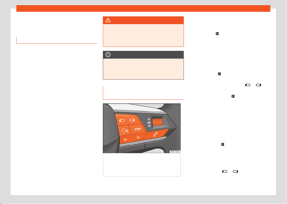
32
Driver information
Instrument cluster opera-
tion
Intr
oduction
With the ignition switched on, it is possible to
read the dierent functions of the display by
scrolling through the menus.
In vehicles with multifunction steering wheel,
the multifunction display can only be operated
with the steering wheel buttons.
Some menu options can only be read when the
vehicle is at a standstill.
Instrument panel menus
The number of menus and information items
available will depend on the vehicle’s electron-
ics and features.
●
Vehicle status ›››page25.
●
Driving data ›››page23.
●
Assist systems.
–
Front Assist On/O ›››page193
–
ACC (only display) ›››page185
–
Lane Assist On/O ›››page196
–
Side Assist On/O ›››page202
●
Navigation.
●
Audio.
●
Telephone.
WARNING
Distracting the driver in any way can lead to
an accident and cause injuries.
●
Never use the menus on the instrument
panel displ
ay while the vehicle is in motion.
NOTICE
After charging or changing the 12-volt bat-
t
ery, check the system settings. If the power
supply is interrupted, the system settings
might be incorrect or deleted.
Operation using the multifunction
steering wheel
Fig.15 Right side of multifunction st
eering
wheel: buttons to the menus and informative
indications on the instrument panel (depending
on the version).
As long as a priority 1 ›››page25 w
arning is ac-
tive, it will not be possible to access any menu.
Some warnings can be confirmed and hidden
with the button
of the multifunction steering
wheel ›››Fig.15.
Sel
ect a menu or an informative display
●
Switch the ignition on.
●
Customisation option: select a user.
●
If a message or vehicle symbol is displayed,
press the button
›››Fig.15; se
veral times if
necessary.
●
To change menus, use buttons
or .
●
To open the menu or the information dis-
pl
ayed, press the button
or wait a few sec-
onds until the menu or the inf
ormative display
opens automatically.
Changing menu settings
●
In the menu displayed, turn the right thumb-
wheel of the multifunction steering wheel until
the desired option of the menu is highlighted.
The option appears framed.
●
Press the button
to make the required mod-
ifications. A mark indicat
es that the system or
function is activated.
Back to menu selection
●
Press the button
or .
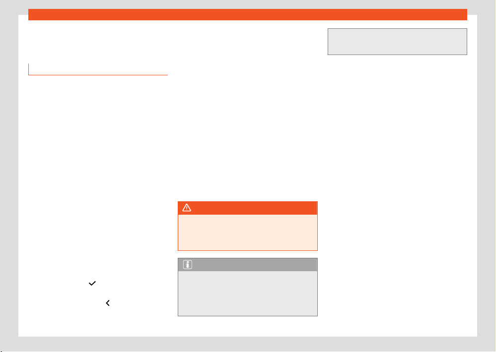
Driver information
33
Infotainment system operation and displays
Infotainment system opera-
tion and displ
ays
Introduction
The infotainment system brings together impor-
tant vehicle functions and systems into a single
central control unit, e.g. air conditioning, menu
settings, radio equipment and the navigation
system.
The actual number of menus available and the
name of the various options will depend on the
vehicle’s electronics and equipment.
General operating information
General information on the operation of the in-
fotainment system, as well as on the warning
and safety instructions that must be taken into
account, is found in ›››page254.
How to move through the dierent menus
and select them
●
Switch the ignition on.
●
If the infotainment system is o, s
witch it on.
●
The dierent menus are selected directly on
the touch screen using texts, icons or buttons.
If the box is checked , the function is activa-
ted.
Pressing the menu button will always take
you to the last menu used.
Any changes made using the settings menus
ar
e automatically saved on closing those me-
nus
Scroll bar: Some menus and functions show
more content above or below those displayed
on the screen at that time, for example, long
lists of settings. Press on the scroll bar and pull
up or down.
Tutorial
The first time you connect the Infotainment sys-
tem, a system tutorial will open with a brief de-
scription of the main functions and how to use
it.
Help
In the Help menu can be found more informa-
tion and tips for using the infotainment system.
WARNING
Any distraction may lead to an accident, with
the risk of injury. Oper
ating the Infotainment
system while driving could distract you from
trac.
Note
After starting the engine with a 12-volt bat-
t
ery that is heavily discharged or recently
replaced, some system settings such as
time, date, personalised comfort settings,
programming and user accounts might be al-
tered or deleted. Check and correct these
settings when the batt
ery is suciently
charged.
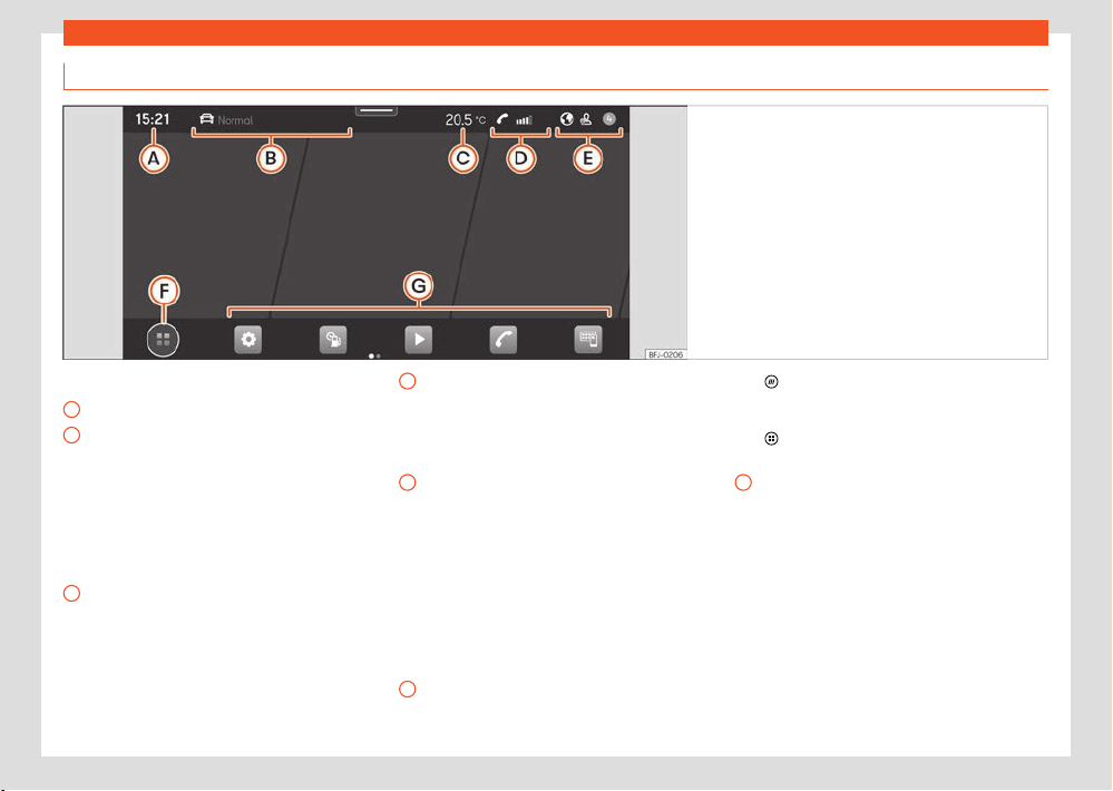
34
Driver information
A
B
C
D
E
F
G
Explanation of the function buttons
Fig.16 Schematic diagr
am: Overview of the
possible function buttons on the screen.
Top part of the screen
Current time.
Driving pr
ofile and navigation informa-
tion. If the user has an active route, both
the time and the distance to the destination
are displayed. If there is no active route,
the driving profile is displayed. On vehicles
with no available driving profile, the current
address is displayed whenever there is no
active route.
Air conditioning information. In vehicles
with heated steering wheels or windscreen
heating, the corresponding icon is dis-
played when these functions are enabled.
If not, the current outside temperature is
displayed.
Telephone information. Information re-
garding your mobile device is displayed:
available network signal strength, estab-
lished Bluetooth connection, unanswered
calls, new messages, battery status, etc.
System customisation based on user
and notifications. Some settings can be
saved in the user accounts of the per-
sonalization function and can therefore
be changed automatically when switching
user accounts.
Bottom part of the screen
Valid for the infotainment system: Connect Sys-
tem.
Main menu display mode:
: main menu with the 6 main functions
divided int
o 2 screens (3 + 3, customisable
by the user by pressing on the function).
: main menu in tile mode (all functions of
the Inf
otainment system).
Direct accesses to the functions of the In-
fotainment system (up to 10 functions, 5 +
5, customisable by the user). By pressing
on the icon, you can select/deselect the
functions in question.
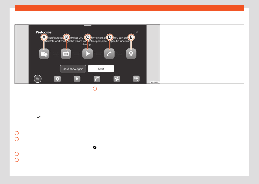
Driver information
35
Infotainment system operation and displays
A
B
C
D
E
Don't show again
Start
End
Initial configur
ation wizard
Fig.17 Schematic diagr
am: Initial configuration
wizard
The initial configur
ation wizard will help you to
set up your Infotainment system the first time
you switch it on.
Whenever you switch on the infotainment sys-
tem, the initial setup screen will be displayed
›››Fig.17 if any parameters have not been set
(marked with “
”) or if the Don'
t show again
function button has not been pressed.
Function buttons:
Press to set day and time.
Press to search and store to memory the
radio stations that have the best reception
at that moment.
Press to go to the Online Media settings.
Press to link your mobile phone to the Info-
tainment system.
Press to select your home address using
your current position or by manually enter-
ing an address.
Disables the possibility of
changing the settings of the Infotainment
system. If you wish to perform the initial
configuration, you must access through
Help.
Starts up the Configuration Wizard.
Once one or more settings have been ap-
plied, press to finalise the setup in the main
menu of the wizard.
Closes the Configuration Wizard.
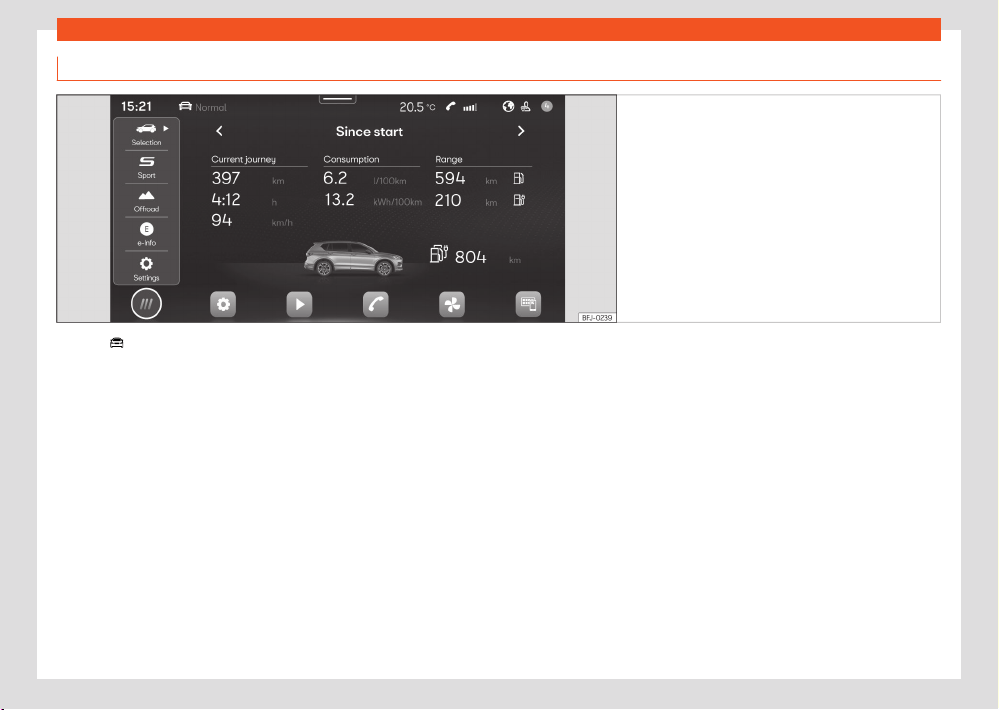
36
Driver information
Vehicle information
Fig.18 Schematic diagr
am: Vehicle information
and status
Pressing
Vehicle > Selection in the
main menu opens the v
ehicle info menu with
the following submenus:
●
Digit
al Cockpit: The dierent options for
displaying the information that will appear in
the Digital Cockpit are shown ›››page16.
●
Driving data: The average consumption,
average speed, distance travelled, trip dura-
tion and autonomy are shown. It has 3 memo-
ries: “Since start”, “Long-term” and “Since refu-
elling”.
●
Vehicle status: The warnings regarding
faults, incidents, memorisation of the tyre pres-
sure or information of the next inspection serv-
ice are displayed.
●
e-Info: Shows the electric range and power
flow. ›››page156
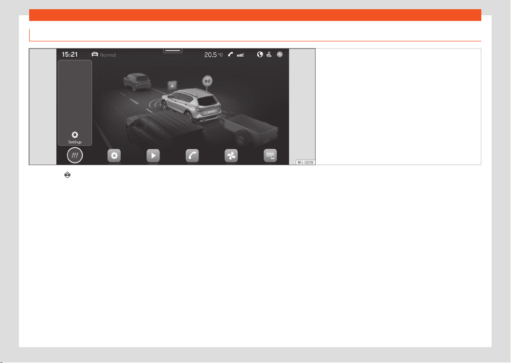
Driver information
37
Infotainment system operation and displays
Assist systems and vehicle settings
Fig.19 Schematic diagr
am: Assist systems and
vehicle settings
Clicking on
Driver assistance fr
om the
main menu opens the menu of vehicle assis-
tants and settings.
The number of assist systems and settings de-
pend on the version and the country in ques-
tion.
●
Automatic parking brake activation
›››page207.
●
Parking assistants ›››page209
●
Trailer Assist ›››page230
●
Activate / deactivate ESC, stabilisation sys-
t
ems and brake assist ›››page174.
●
Switch the Start-Stop system on / o
›››page158
●
Adaptive cruise control (ACC) ›››page185.
●
Lane Assist (lane departure warning system)
›››page196.
●
Emergency brake assistance system (Front
Assist) ›››page193.
●
Fatigue detection ›››page25
●
Detection of road signs ›››page27
●
Side assist ›››page202
38
Safety
1)
Depending on the version/market.
Safety
Saf
e driving
Safety first!
WARNING
●
This manual contains important informa-
tion about the oper
ation of the vehicle, both
for the driver and the passengers. The other
sections of the on-board documentation also
contain further information that you should
be aware of for your own safety and for the
safety of your passengers.
●
Ensure that the on-board documentation is
kept in the vehicle at all times. This is espe-
cially important when lending or selling the
vehicle to another person.
Before driving
F
or your own safety and the safety of your
passengers, always note the following points
before every trip:
●
Make sure that the vehicle's lights and turn
signal
s are working properly.
●
Check tyre pressure.
●
Ensure that all windows provide a clear and
good vie
w of the surroundings.
●
Make sure all luggage is secured
›››page286.
●
Make sure that no objects can interfere with
the pedal
s.
●
Adjust front seat, head restraint and mirrors
properly according to your size.
●
Ensure that the passengers in the rear seats
always have the head restraints in the in-use
position ›››page111.
●
Instruct passengers to adjust the head re-
straints according to their height.
●
Protect children with appropriate child seats
and properly applied seat belts ›››page55.
●
Assume the correct sitting position. Instruct
your passengers also to assume a proper sit-
ting position ›››page39.
●
Fasten your seat belt securely. Instruct your
passengers al
so to fasten their seat belts prop-
erly ›››page41.
Factors influencing safety
As a driver, you are responsible for yourself and
your passengers.
●
Always pay attention to tr
ac and do not get
distracted by passengers or telephone calls.
●
Never drive when your driving ability is im-
paired (e.g. by medication, alcohol, drugs).
●
Observe trac laws and speed limits.
●
Always reduce your speed as appropriate for
r
oad, trac and weather conditions.
●
When travelling long distances, take breaks
regularly - at least every two hours.
●
If possible, avoid driving when you are tired or
stressed.
WARNING
Driving under the influence of al
cohol, drugs,
medication or narcotics may result in severe
accidents and even loss of life.
●
Alcohol, drugs, medication and narcotics
may significantly alter perception, aect re-
action times and safety while driving, which
could result in the loss of control of the vehi-
cle.
Safety equipment
Never put your safety or the safety of your pas-
sengers in danger. In the event of an accident,
the safety equipment may reduce the risk of
injury. The following points cover part of the
safety equipment in your SEAT
1)
:
●
Optimised seat belts for all seats.
●
Seat belt tensioners on the driver, front pas-
senger and r
ear side seats.
●
Seat belt force limiters on the driver, front
passenger and r
ear side seats.
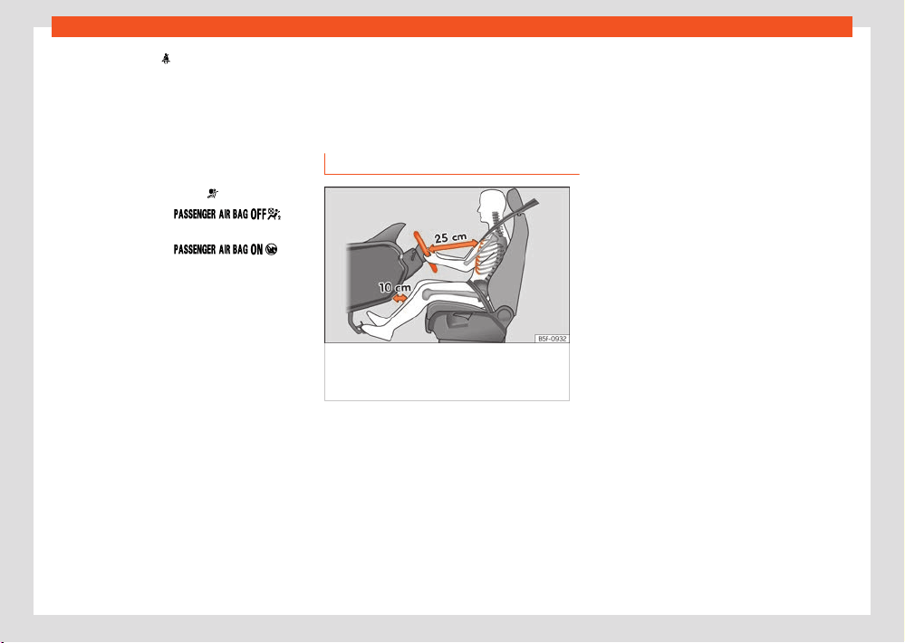
Safety
39
Correct sitting position of vehicle occupants
●
Red warning lamp
and, if applicable, seat
belt st
atus indication.
●
Belt height adjustment for the front seats.
●
Front airbags for driver and passenger.
●
Side airbags for driver and passenger.
●
Head airbags on both sides of the vehicle.
●
Knee airbag.
●
Yellow airbag control lamp
.
●
Yellow warning lamp on
the centr
e console.
●
Yellow warning lamp
on
the centr
e console.
●
Control units and sensors.
●
Optimised and height-adjustable headrests.
●
Adjustable steering column.
●
ISOFIX/i-Size anchor points for child seats.
●
Child seat top tether attachment points.
The safety equipment mentioned above works
together to provide you and your passengers
with the best possible protection in the event
of an accident. However, these safety systems
can only be eective if you and your passen-
gers are sitting in a correct position and use this
equipment properly.
Safety is everybody's business.
Correct sitting position of
vehicle occupants
Correct position on the seat
Fig.20 The corr
ect distance between the
driver and the steering wheel must be at least
25 cm (10 inches).
The correct sitting positions for the driver and
passengers ar
e shown below.
If your physical constitution prevents you from
maintaining the correct sitting position, contact
a specialised workshop for help with any spe-
cial devices. The seat belt and airbag can only
provide optimum protection if a correct sitting
position is adopted. SEAT recommends taking
your car in for technical service.
For your own safety and to reduce the risk of
injury in the e
vent of an accident or sudden
braking or manoeuvre, SEAT recommend the
following positions:
Valid for all vehicle occupants:
●
Adjust the headrest so that its upper edge is
at the same level as the top of your head, or as
close as possible to the same level as the top of
your head and under no circumstances below
eye level . Keep the back of your neck as close
as possible to the headrest.
●
Short people must fully lower the headrest
completely, even if your head is below its upper
edge.
●
Tall people must fully raise the headrest.
●
Always keep your feet in the footwell while
the vehicle is in motion.
●
Adjust and fasten your seat belt correctly
›››page41.
The following also applies to the driver:
●
Given that the vehicle is equipped with ad-
justable headrests, move the headrest as close
as possible to the rear of the head.
●
Move the seat backrest to an almost upright
position so that your back rests completely
against it.
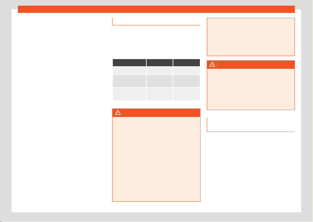
40
Safety
●
Adjust the steering wheel so that it is at a
dist
ance of at least 25 cm (10 inches) from the
sternum ›››Fig.20 and can hold it with both
hands on the sides, on the outside, with the
arms slightly flexed.
●
The steering wheel must always point to-
wards the chest and never towards the face.
●
Adjust the seat lengthwise so that you can
fully step on the pedals with your knees slightly
bent and there is a distance between the knee
area and the instrument panel of at least 10 cm
(4 inches).
●
Adjust the height of the seat so that you can
reach the top of the steering wheel.
●
Always keep both feet in the footwell so that
you have the vehicle under control at all times.
For the passenger, the following applies:
●
Given that the vehicle is equipped with ad-
justable headrests, move the headrest as close
as possible to the rear of the head.
●
Move the seat backrest to an almost upright
position so that your back rests completely
against it.
●
Move the seat as far back as possible (mini-
mum 25 cm between the chest and the instru-
ment panel check translation). If you are sitting
closer than 25 cm, the airbag system cannot
protect you properly.
Number of seats
The v
ehicle has 5 or 7 seats, depending on the
features. All seats are equipped with a safety
belt.
No one taller than 1.60 m should sit on the
third row of seats.
5 seats 7 seats
Seats in the front 2 2
Seats in the sec-
ond r
ow
3 3
Seats in the third
row
– 2
WARNING
Sitting in an incorrect position may increase
the risk of se
vere or lethal injuries in the
event of sudden braking or manoeuvring, in
case of collision or accident and if the air-
bags deploy.
●
Before starting the car, all passengers
must be sitting in a correct position and stay
like that for the entire journey. This also ap-
plies to a correct use of the seat belt.
●
The maximum amount of people in the ve-
hicle is the same as the amount of seats with
seat belts.
●
For children, always use a protection sys-
tem that is approved and suited for their
weight and height ›››page55.
●
While driving, always keep your feet in the
f
ootwell. Never place them over the seat or
the dash panel, for example, or outside the
window. Otherwise the airbag and seat belt
may oer insucient protection and also in-
crease the risk of injury in the event of an
accident.
WARNING
If people taller than 1.60 m travel in the third
r
ow of seats, they may receive severe head
injuries in the event of an accident.
●
Never transport anyone taller than 1.60m
on the third row of seats.
●
When closing the rear lid, always be mind-
ful of the passengers of the rearmost seats.
Risks of sitting in an incorrect posi-
tion
If seat belts are worn incorrectly or not at all,
the risk of severe or lethal injuries increases.
Seat belts can provide optimal protection only
if the belt web is properly worn. Incorrect sitting
positions substantially reduce the protective
function of seat belts and, therefore, increase
the risk of severe or even lethal injuries. The risk
of severe or fatal injuries is especially height-
ened when a deploying airbag strikes a vehicle
occupant who has assumed an incorrect sitting
position. The driver is responsible for all people,
particularly children, inside the vehicle.
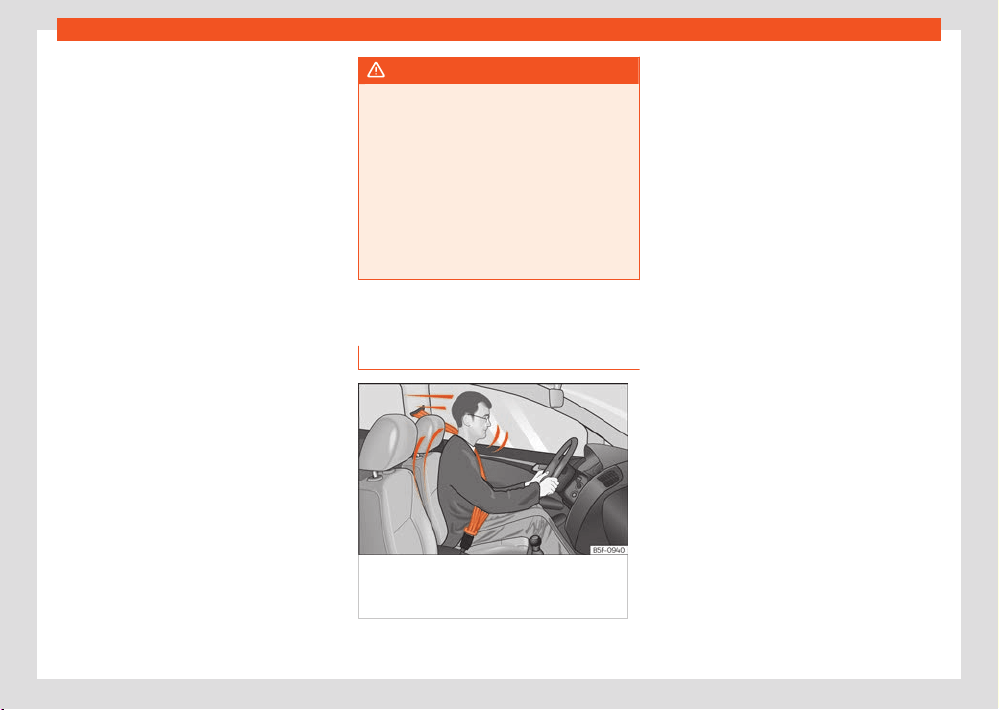
Safety
41
Seat belts
The following list contains examples of incor-
r
ect sitting positions that could be dangerous
for all vehicle occupants.
When the vehicle is in motion:
●
Never stand in the vehicle.
●
Never stand on the seats.
●
Never kneel on the seats.
●
Never tilt your seat backrest too far to the
rear.
●
Never lean against the instrument panel.
●
Never lie on the rear seats.
●
Never sit on the front edge of a seat.
●
Never sit sideways.
●
Never lean out of a window.
●
Never put your feet out of a window.
●
Never put your feet on the instrument panel.
●
Never place your feet on the bench or on the
backrest of the seat.
●
Never travel in a footwell.
●
Never sit on the armrests.
●
Never travel without wearing the seat belt.
●
Never travel in the luggage compartment.
WARNING
Sitting in an incorrect position increases the
risk of se
vere or fatal injuries in the event
of accidents and sudden braking or manoeu-
vres.
●
All occupants must sit correctly during the
journey and wear the seat belt correctly.
●
Occupants of the vehicle that are not sit-
ting correctly, not wearing the seat belt or
are not at a proper distance of the airbag risk
suering very serious or lethal injuries, espe-
cially if the airbags deploy and strike them.
Seat belts
Introduction
Fig.21 Driv
ers with properly worn seat belts
will not be thrown forward in the event of
sudden braking.
Properly worn seat belts hold the occupants
in the pr
oper position. They also help prevent
uncontrolled movements that may result in seri-
ous injury and reduce the risk of being thrown
out of the vehicle in case of an accident.
Vehicle occupants wearing their seat belts cor-
rectly benefit greatly from the ability of the
belts to absorb kinetic energy. In addition, the
front part of your vehicle and other passive
safety features (such as the airbag system) are
designed to absorb the kinetic energy released
in a collision. Taken together, all these features
reduce the releasing kinetic energy and conse-
quently, the risk of injury. This is why it is so
important to fasten seat belts before every trip,
even when "just driving around the corner".
Ensure that your passengers wear their seat
belts as well. Accident statistics have shown
that wearing seat belts is an eective means of
substantially reducing the risk of injury and im-
proving the chances of survival when involved
in a serious accident. Furthermore, properly
worn seat belts improve the protection provi-
ded by airbags in the event of an accident. For
this reason, wearing a seat belt is required by
law in most countries.
Although your vehicle is equipped with airbags,
the seat belts must be fastened and worn. The
front airbags, for example, are only triggered in
some cases of head-on collision. The front air-
bags will not be triggered during minor frontal
or side collisions, rear-end collisions, overturns
or accidents in which the airbag trigger thresh-
old value in the control unit is not exceeded.

42
Safety
Important safety instructions for the use of
seat belts
●
Always wear the seat belt as described in this
section.
●
Ensure that the seat belts can be fastened at
all times and ar
e not damaged.
WARNING
●
If seat belts are worn incorrectly or not at
all, the risk of se
vere injuries increases. The
optimal protection from seat belts can be
achieved only if you use them properly.
●
Never allow two passengers (even chil-
dren) to share the same seat belt.
●
Never unbuckle a seat belt while the vehi-
cle is in motion. Risk of fatal injury.
●
The seat belt should never lie on hard or
fragile objects (such as glasses or pens, etc.)
because this can cause injuries.
●
Do not allow the seat belt to be damaged
or jammed, or to rub on any sharp edges.
●
Never wear the seat belt under the arm or
in any other incorrect position.
●
Bulky and unfastened clothing (such as an
overcoat over a sweater) impairs the proper
fit and function of the seat belts, reducing
their capacity to protect.
●
The slot in the seat belt buckle must not be
blocked with paper or other objects, as this
can prevent the latch plate from engaging
securely.
●
Never use seat belt clips, fastening rings or
similar items to alter the position of the belt
webbing.
●
Frayed or torn seat belts or damage to
the connections, belt retractors or parts of
the buckle could cause severe injuries in the
event of an accident. Therefore, you must
check the condition of all seat belts at regu-
lar intervals.
●
Seat belts which have been worn in an ac-
cident and have been stretched must be re-
placed by a specialised workshop. Renewal
may be necessary even if there is no ap-
parent damage. The belt anchorage should
also be checked.
●
Do not attempt to repair a damaged seat
belt yourself. The seat belts must not be re-
moved or modified in any way.
●
The belts must be kept clean, otherwise
the retractors may not work properly.
Seat belt buckled indication
It lights up red
The driv
er or passenger has not fastened
the seat belt.
The control lamp
lights up to remind the
driv
er to fasten their seat belt.
Before starting the vehicle:
●
Fasten your seat belt securely.
●
Instruct your passengers to fasten their seat
belts pr
operly before driving o.
●
Protect children by using a child seat ac-
cording to the child's height and weight
›››page55.
When starting to drive, if the vehicle's speed
exceeds approx. 25km/h (15mph) and the seat
belts are not fastened or are unfastened while
driving, a warning sound will be heard for a few
seconds. In addition, the warning lamp
on the
instrument clust
er display flashes.
The lamp
goes out when the driver and pas-
senger seat belts ar
e fastened with the ignition
switched on.
Rear seat belts fastened display
Fig.22 Instrument clust
er: indication of the
status of the rear seat seat belts.

Safety
43
Seat belts
Depending on the version of the model, when
the ignition is s
witched on, the status display of
the belts ›››Fig.22 informs the driver on the in-
strument panel display whether the occupants
of the rear seats have their seat belts fastened.
Depending on the seat occupancy and the sta-
tus of the seat belts, the following symbols light
up in dierent colours:
The white symbol indicates that the cor-
responding seat is empty.
A green symbol indicates that the seat is
occupied and the occupant is wearing the
seat belt.
A red symbol indicates that the seat is oc-
cupied and the occupant is not wearing
the seat belt.
If a rear seat occupant unfastens his/her seat
belt while driving, the
symbol lights up per-
manently in r
ed for that seat. In addition, the
red warning light
flashes on the instrument
clust
er screen. If you drive faster than approx.
25 km/h (15 mph), an audio signal sounds for a
few seconds.
If a seat belt is fastened or unfastened while
driving in some of the rear seats, the seat belt
status is displayed for approximately 30 sec-
onds.
Head-on collisions and the laws of
physics
Fig.23 A driv
er not wearing a seat belt may be
thrown forward violently.
Fig.24 Any r
ear seat occupants not wearing
a seat belt may be thrown forward violently,
hitting the driver who is wearing the seat belt.
The eects of the l
aws of physics in the case of
a head-on collision are easy to explain: the mo-
ment a vehicle starts moving, a type of energy
called “kinetic energy” starts acting on both the
vehicle and its passengers.
The amount of “kinetic energy” depends on the
speed of the vehicle and on the weight of the
vehicle and of its passengers. The higher they
are, the more energy there is to be “absorbed”
in the event of an accident.
The most significant factor, however, is the
speed of the vehicle. If the speed doubles from
25 km/h (15 mph) to 50 km/h (30mph), for
example, the corresponding kinetic energy is
multiplied by four.
Given that the passengers of the vehicle in our
example do not have their seat belts fastened,
in the event of a collision the entire amount of
the passengers' kinetic energy will be only ab-
sorbed by the mentioned impact.
Even at speeds of 30 km/h (19 mph) to 50 km/h
(30 mph), the forces acting on bodies in a colli-
sion can easily exceed one tonne (1000 kg). At
greater speed these forces are even higher.
Vehicle occupants not wearing seat belts are
not “attached” to the vehicle. In a head-on col-
lision, they will move forward at the same speed
their vehicle was travelling just before the im-
pact. This example applies not only to head-on
collisions, but to all accidents and collisions.
Even at low speeds the forces acting on the
body in a collision are so great that it is not pos-
sible to brace oneself with one's hands. In the
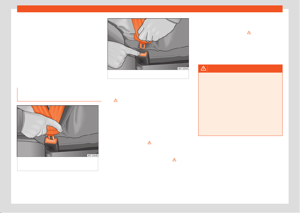
44
Safety
event of a head-on collision, vehicle occupants
not w
earing a seat belt will be thrown uncon-
trollably forward and will collide, for example,
against the steering wheel, instrument panel or
windscreen ›››Fig.23.
It is also important for rear passengers to wear
seat belts properly, as they could otherwise be
thrown forward violently through the vehicle in-
terior in an accident. If a rear seat occupant
is not wearing a seat belt, they are not only en-
dangering themselves but also the occupants
of the front seats ›››Fig.24.
Fastening and unfastening the seat
belt
Fig.25 Insert the l
atch plate of the seat belt
into the buckle.
Fig.26 R
elease the seat belt's latch plate.
Properly worn seat belts hold the vehicle occu-
pants in the position that most pr
otects them
in the event of an accident or sudden braking
›››
.
F
astening the seat belt
Fasten your seat belt before each trip.
●
Adjust the front seat and head restraint cor-
rectly ›››page39.
●
Engage the seat backrest of the rear seat in
an upright position ›››
.
●
Pull the latch plate and place the belt web-
bing e
venly across your chest and lap. Do not
twist the seat belt when doing so ›››
.
●
Insert the buckle plate in the buckle of the
corr
ect seat ›››Fig.25.
●
Pull the belt to ensure that the latch plate is
securely engaged in the buckle.
Releasing the seat belt
Only unfasten the seat belt when the vehicle
has come to a standstill ›››
.
●
Press the red button on the buckle ›››Fig.26.
The l
atch plate is released from the buckle.
●
Guide the belt back by hand so that it rolls up
easily and the trim will not be damaged.
WARNING
●
The seat belt cannot oer its full pr
otec-
tion unless the seat backrest is in an upright
position and the seat belt is worn correctly,
according to your size.
●
Unbuckling your seat belt while the vehicle
is in motion can cause severe or fatal injuries
in the event of an accident or sudden brak-
ing.
●
The seat belt itself, or a loose seat belt,
can cause severe injuries if the belt moves
from hard areas of the body to soft areas
(e.g. the stomach).
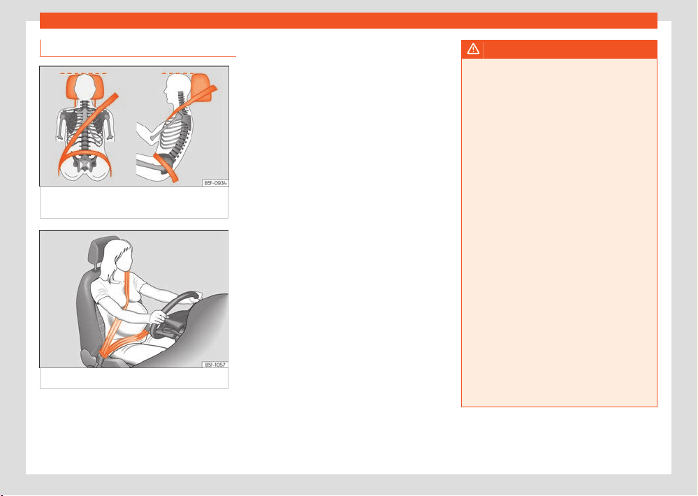
Safety
45
Seat belts
Correct position of the seat belt
Fig.27 Corr
ect seat belt and headrest
positions, viewed from front and the side.
Fig.28 P
osition of seat belt during pregnancy.
Seat belts oer their maximum pr
otection in
the event of an accident and reduce the risk
of sustaining severe or fatal injuries only when
they are properly positioned. Furthermore, if the
webbing is correctly positioned, the seat belt
will hold the vehicle occupants in the optimum
position t
o ensure the airbag provides the max-
imum protection. The seat belt must therefore
always be worn and the webbing correctly
positioned.
Incorrectly worn seat belts can cause severe or
even fatal injuries ›››page39, Correct sitting
position of vehicle occupants.
●
The shoulder part of the seat belt must lie
on the centre of the shoulder, never across the
neck or the arm, under the arm or behind the
shoulder.
●
The lap part of the seat belt must lie across
the pelvis, never across the stomach.
●
The seat belt must lie flat and fit comfortably.
Pull the belt tight if necessary to take up any
slack.
In the case of pregnant women, the seat belt
should pass uniformly over the chest and as
low as possible through the pelvic area with the
strap flat so it does not press down on the ab-
domen; in addition, it must be used throughout
the entire pregnancy ›››Fig.28.
Adapting the position of the belt webbing to
your size
The seat belt can be adapted using the follow-
ing equipment:
●
Front seat belts with height adjustment.
●
Front seat height adjustment.
WARNING
An incorrectly worn seat belt web can cause
se
vere or fatal injuries in the event of an acci-
dent.
●
The shoulder part of the seat belt must lie
on the centre of the shoulder, never across
the neck or the arm.
●
The seat belt must lie flat and fit comforta-
bly on the torso
●
The lap part of the seat belt must lie across
the pelvis, never across the stomach. The
seat belt must lie flat and fit comfortably on
the pelvis Pull the belt tight if necessary to
take up any slack.
●
In the case of pregnant women, the ab-
dominal strap of the seat belt should pass
as low as possible across the pelvic area,
resting flat and “surrounding” the abdomen
›››Fig.28.
●
Do not twist the seat belt while it is fas-
tened.
●
Once the seat belt is positioned correctly,
don't pull it away from your body with your
hand.
●
Do not lie the seat belt across rigid or frag-
ile objects, e.g. glasses, pens or keys.
●
Never use seat belt clips, retaining rings or
similar instruments to alter the position of the
belt webbing.
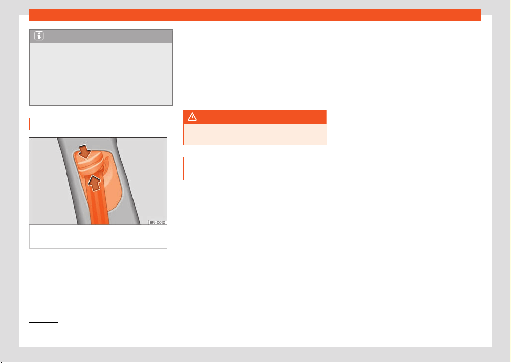
46
Safety
1)
Only if fitt
ed with the PreCrash System.
Note
If your physical constitution prevents you
fr
om maintaining the correct position of the
belt webbing, contact a specialised work-
shop for help with any special devices to en-
sure the optimum protection of the seat belt
and airbag. SEAT recommends taking your
car in for technical service.
Seat belt height adjustment
Fig.29 Near the fr
ont seats: seat belt height
regulator.
Using the height adjusters for the front seats
and the out
er seats of the second row, the po-
sition of the seat belts can be adjusted in the
shoulder area according to the height of the
occupant:
●
Keep the guide device pressed down in the
dir
ection of the arrow ›››Fig.29.
●
Move the guide device up or down until the
seat belt lies over the centre of your shoulder
›››page45.
●
Release the guide device.
●
Pull the belt sharply to check that the device
is engaged securely.
WARNING
Never adjust the belt height while the vehicle
is in motion.
Automatic retractor, tensioner and
belt f
orce limiter
Vehicle seat belts are part of the vehicle’s
safety system ›››page39. This system has the
following important functions:
Automatic belt retractor
The seat belt shoulder straps on the driver's
and front passenger seats, as well as those on
the rear side seats (and, depending on equip-
ment, also the seat belt of the central rear
seat) are fitted with automatic retractors. This
device ensures complete freedom of movement
when the shoulder strap is pulled gently or
during normal driving. However, during sudden
braking, when driving in the mountains, around
bends and when accelerating, the retractor
locks the seat belt if it extends rapidly.
In critical driving situations, e.g. in the event
of emergency braking or in the case of over-
steer and understeer, the proactive occupant
protection can tension the front seat belts auto-
matically if they are worn
1)
. The two belts are
loosened again if an accident does not happen
or when the critical situation passes. Proactive
occupant protection is ready to operate again
›››page47.
Seat belt tensioner
The seat belts on the front seats and, depend-
ing on the equipment, side rear seats are fitted
with tensioners.
The tensioners are activated by sensors in the
event of severe head-on, side and rear colli-
sions, and tension the seat belts in a direction
opposite their extension.
If the seat belt is slack, the tensioner tightens
it. This cushions the movement of occupants
forwards towards the impact.
The belt pre-tensioners work in combination
with the airbag system. In case of overturn, the
pre-tensioners do not activate unless the head
airbags are deployed.
When activated, a fine powder may be re-
leased. This is completely normal and it is not
an indication of fire in the vehicle.
Safety
47
PreCrash system
1)
Only if fitt
ed with the PreCrash System.
Reversible belt tensioning (proactive occu-
pant pr
otection)
A reversible tensioning of the seat belts may
occur in certain driving situations ›››page47.
For example:
●
in the event of sudden brakes
●
in the event of oversteering or understeering
●
in the event of minor collisions
Belt force limiter
Depending on the equipment and the country
in question, in the event of an accident, the seat
belt force limiter reduces the force the seat belt
exerts on the body.
Note
●
After certain driving situations, the reversi-
bl
e belt tensioners may be left permanently
tensioned
1)
. In this case, to loosen the belt, it
must be removed manually while the vehicle
is stationary and then replaced correctly.
●
The relevant safety requirements must be
observed if the vehicle or any components of
the system are to be scrapped. Specialised
workshops are aware of these requirements.
Maintenance and disposal of seat
belt tensioners
The belt tensioners are components of the seat
belts that are installed in the seats of your
vehicle. If you work on the belt tensioners or
remove and install parts of the system when
performing other repair work, the seat belt may
be damaged. The consequence may be that,
in the event of an accident, the belt tensioners
function incorrectly or may not function at all.
So that the eectiveness of the seat belt ten-
sioner is not reduced and that removed parts
do not cause any injuries or environmental pol-
lution, regulations, which are known to the spe-
cialised workshops, must be observed.
WARNING
Improper handling and home repairs to seat
belts, aut
omatic retractors and belt tension-
ers may increase the risk of serious or fa-
tal injuries. The tensioners may not activate,
even though they should, or they may acti-
vate unexpectedly.
●
Never repair, adjust, or disassemble and
reassemble seat belt components or ten-
sioners. Always have this work carried out by
a specialist workshop.
●
Seat belts, tensioners and their automatic
retractors cannot be repaired and have to be
replaced.
For the sake of the environment
Airbag modules and belt tensioners may
cont
ain perchlorate.
Observe the legal requirements for their dis-
posal.
PreCrash system
How it works
The PreCrash system is an assistance system
that actives a series of measures to protect the
occupants of the vehicles in potentially risky
situations, but which cannot prevent a collision.
It only works completely if no special driving
profile is selected and if there are no operating
anomalies.
Basic features
Depending on the legal provisions of the coun-
try and the features of the vehicle, in critical
situations (e.g. in certain cases of emergency
braking or loss of control of the vehicle by the
driver) the following functions can be activated
separately or at the same time when the vehi-
cle is travelling faster than approximately 30
km/h (20 mph).
●
Reversible tensioning of front seat belts that
ar
e fastened.
●
Operation of the hazard warning lights.

48
Safety
●
Automatic closing of the windows until they
ar
e just cracked open and, depending on the
equipment, of the sunroof.
●
In the event of overturning, depending on the
equipment, activation of the belt tensioners.
Depending on how critical the driving situation
is, the belts are either tightened individually, or
both belts at the same time.
In addition to Front Assist
In vehicles with Front Assist ›››page193, within
the limits of the system, information is assessed
on the risk of collision with the vehicle in front.
The functions of the PreCrash system may also
be activated if there is a high likelihood of a
rear-end collision, or during the activation of
Front Assist.
In addition to Side Assist
In vehicles with lane assist ›››page202, within
the limitations of each system, information is
assessed on the risk of collision with trac to
the rear of the vehicle. If a rear-end collision
is highly likely, the functions of the PreCrash
system may also be activated. In this situation,
the hazard warning lights are turned on with a
higher frequency of flashes.
In addition to the Emergency Assist system
In vehicles with emergency assist, driver status
information is assessed within the limitations of
this system. The following PreCrash systems
may be activated if a lack of activity is detec-
ted:
●
Reversible seat belt tensioning of the driver's
seat belt.
●
Automatic closing of the windows until they
are just cracked open and, depending on the
equipment, of the sunroof.
Activation of the PreCrash system
The PreCrash system can be partially deac-
tivated by deactivating the traction and/or
stability control, depending on the equip-
ment. When these vehicle safety controls are
switched on (by default, every time the ignition
is turned on), the system is fully activated.
Driving profile selection settings
In vehicles with driving profile selection, Pre-
Crash adapts to suit the special vehicle
configuration of the corresponding profile
›››page170.
Limited operation
The PreCrash system is not available or only
has limited availability in the following situa-
tions:
●
When the TCS and/or ESC is o.
●
When driving in reverse.
●
When the airbag control unit is not operating
properly.
●
When there is a fault in the system itself, in the
ESC or in the Front Assist.
Troubleshooting
If the PreCrash is not working correctly, the
message System unavailable or System
with limited functions is shown perma-
nently on the instrument cluster screen. Get the
system checked by a SEAT Ocial Service.
WARNING
The PreCrash system cannot overcome the
limits imposed by the l
aws of physics; it only
works within the limits of the system. Risks
that compromise safety are never justified by
the use of this system. The system is not a re-
placement for driver awareness and cannot
prevent a collision.
●
Adapt your speed and safe distance to
the vehicle in front of you at all times to suit
the visibility, weather, road and trac condi-
tions.
●
The system is not always able to recognise
objects.
●
The system may not react to people or
animals or objects that cross length-wise or
that are hard to detect.
Safety
49
Airbag system
●
Metallic objects (e.g. fences) or other ele-
ments of the public r
oad or adverse weather
conditions can hinder its operation and thus
its ability to detect collision risk.
●
Never ignore the warning lamps that light
up or the messages shown on the dashboard.
WARNING
Distracting the driver in any way can lead to
an accident and cause injuries.
●
Never change settings on the Infotainment
Syst
em while driving.
Airbag system
Why is it so important to wear a seat
belt and to sit correctly?
For the inflating airbags to achieve the best
protection, the seat belt must always be worn
properly and the correct sitting position must
be assumed.
The airbag system is not a substitute for seat
belts, but it is an integral part of the vehicle's
overall passive safety system. Please bear in
mind that the airbag system can only work ef-
fectively when the vehicle occupants are wear-
ing their seat belts correctly and have adjus-
ted the head restraints properly. Therefore, it is
most important to properly wear the seat belts
at all times, not only because this is required by
law in most countries, but also for your safety
›››page41, Seat belts.
The airbag inflates in a matter of seconds, so if
you are not properly seated when the airbag is
triggered, you may sustain fatal injuries. There-
fore, it is essential that all vehicle occupants as-
sume a correct sitting position while travelling.
Sharp braking before an accident may cause a
passenger not wearing a seat belt to be thrown
forward into the area of the deploying airbag.
In this case, the inflating airbag may inflict criti-
cal or fatal injuries on the occupant. This also
applies to children.
Always maintain the greatest possible distance
between yourself and the front airbag. This
way, the front airbags can completely deploy
when triggered, providing their maximum pro-
tection.
The most important factors for triggering the
airbag are the type of accident, the angle of
impact and the vehicle speed.
Whether or not the airbags are activated de-
pends primarily on the vehicle deceleration
rate resulting from the collision and detected
by the control unit. If the vehicle deceleration
occurring during the collision and measured by
the control unit remains below the specified
reference values, the front, side and/or curtain
airbags will not be triggered. Take into account
that the visible damage in a vehicle involved
in an accident, no matter how serious, is not a
determining factor for the airbags to have been
activated.
WARNING
Wearing the seat belt incorrectly or assum-
ing an incorr
ect sitting position can lead to
critical or fatal injuries
●
All vehicle occupants, including children,
who are not properly belted can sustain criti-
cal or fatal injuries if the airbag is triggered.
Children up to 12 years old should always
travel on the rear seat. Never transport chil-
dren in the vehicle if they are not restrained
or the restraint system is not appropriate for
their age, size or weight.
●
To reduce the risk of injury from an inflating
airbag, always wear the seat belt properly
›››page41.
Description of the airbag system
The airbag system oers additional protection
for the occupants in combination with the seat
belts.
The airbag system comprises the following
modules (as per vehicle equipment):
●
Electronic control unit
●
Front airbags for driver and passenger
●
Knee airbag for the driver
●
Side airbags
50
Safety
●
Head airbag
●
Airbag control lamp
on the instrument
panel ›››page51
●
Key-operated switch for front passenger air-
bag
●
Control lamp for disabled/enabled status of
the fr
ont passenger airbag.
The airbag system operation is monitored elec-
tronically. The airbag control lamp will illumi-
nate for a few seconds every time the ignition is
switched on (self-diagnosis).
There is a fault in the system if the control
lamp
:
●
does not light up when the ignition is switched
on ›››page51,
●
turns o aft
er 4 seconds after the ignition is
switched on,
●
turns o and then lights up again after the
ignition is switched on,
●
illuminates or flashes while the vehicle is mov-
ing.
The airbag system is not triggered if:
●
the ignition is switched o
●
there is a minor frontal collision
●
there is a minor side collision
●
there is a rear-end collision
●
in the event of the vehicle overturning if the
dynamic characteristics measured by the con-
trol unit are too low,
●
the impact speed is lower than the reference
value programmed in the control unit.
WARNING
●
The seat belts and airbags can only pro-
vide maximum pr
otection if the occupants
are seated correctly ›››page39.
●
If a fault has occurred in the airbag sys-
tem, have the system checked immediately
by a specialised workshop. Otherwise there
is a danger that during a collision, the system
may fail to trigger, or not trigger correctly.
Airbag activation
The airbags deploy extremely rapidly, within
thousands of a second, to provide additional
protection in the event of an accident. A fine
dust may develop when the airbag deploys.
This is normal and it is not an indication of fire in
the vehicle.
The airbag system is only ready to function
when the ignition is on.
In special accidents instances, several airbags
may activate at the same time.
In the event of minor head-on and side colli-
sions, rear-end collisions, overturning or rollover
of the vehicle, airbags do not activate.
Airbags only activate if the vehicle overturns in
the hybrid plug-in version of the vehicle.
Activation factors
The conditions that lead to the airbag system
activating in each situation cannot be general-
ised. Some factors play an important role, such
as the properties of the object the vehicle hits
(hard/soft), angle of impact, vehicle speed, etc.
Deceleration trajectory is key for airbag activa-
tion.
The control unit analyses the collision trajec-
tory and activates the respective restraint sys-
tem.
If the deceleration rate is below the predefined
reference value in the control unit the airbags
will not be triggered, even though the accident
may cause extensive damage to the car.
The following airbags are triggered in seri-
ous head-on collisions:
●
Driver airbag.
●
Front passenger front airbag
●
Knee airbag for the driver.
The following airbags are triggered in seri-
ous side-on collisions:
●
Curtain (head) airbag on the side of the acci-
dent.
●
Front side airbag on the side of the accident.
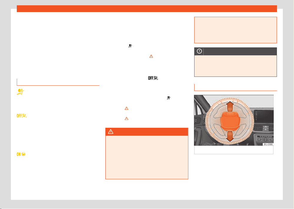
Safety
51
Airbag system
In an accident with airbag activation:
●
the interior lights switch on (if the interior light
s
witch is in the courtesy light position);
●
the hazard warning lights switch on;
●
all doors are unlocked;
●
the fuel supply to the engine is cut;
●
in hybrid vehicles, the high voltage system is
switched o;
●
an emergency call is started.
Airbag system control lamps
Lights up on the instrument cluster
F
ault in the airbag system and seat belt
tensioners. Have the system checked im-
mediately by a specialised workshop.
It lights up on the dash panel
Front passenger front airbag deactivated.
Check if the airbag should be kept deacti-
vated.
OR: Fault in the airbag system. Have the
system checked immediately by a special-
ised workshop.
It lights up on the dash panel
Front passenger front airbag activated. The
control lamp turns o automatically 60
seconds after the ignition is switched on.
Several warning and control lamps light up for
a f
ew seconds when the ignition is switched
on, signalling that the function is being verified.
They will switch o after a few seconds.
If the airbag and seat belt tensioner system
control lamp
remains on or flashes, it indi-
cat
es a malfunction in the airbag and seat
belt tensioner system ›››
. Have the system
check
ed immediately by a specialised work-
shop.
If the front passenger airbag has been deacti-
vated, the warning lamp
remains lit on the
r
oof console to remind you that the airbag is
deactivated. If, with the front passenger airbag
deactivated, this lamp does not remain lit or
if it is lit along with the control lamp
on the
instrument panel, ther
e is a fault in the airbag
system ›››
. If the control lamp is flashing,
ther
e is a fault in the disabling of the airbag
system ›››
. Have the system checked imme-
diat
ely by a specialised workshop.
WARNING
In the event of a fault in the airbag and seat
belt t
ensioner system, the airbags and seat
belts may not trigger correctly, may fail to
trigger or may even trigger unexpectedly.
●
The vehicle occupants run the risk of sus-
taining severe or fatal injuries. Have the sys-
tem checked immediately by a specialised
workshop.
●
Do not mount a child seat in the front pas-
senger seat or remove the mounted child
seat! The front passenger front airbag may
deploy during an accident in spite of the
fault.
NOTICE
Always pay attention to any lit control lamps
and t
o the corresponding descriptions and
instructions to avoid damage to the vehicle
or harm to the occupants.
Front airbags
Fig.30 Driv
er’s airbag in the steering wheel.
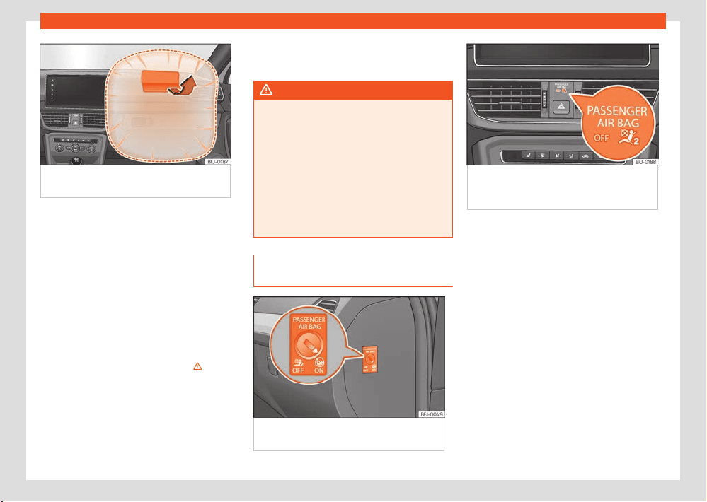
52
Safety
Fig.31 Fr
ont passenger airbag located in dash
panel.
The driver's front airbag is housed in the steer-
ing wheel and that of the fr
ont passenger, on
the dash panel. Airbags are identified by the
word “AIRBAG”.
The airbag covers open and remain attached
to the steering wheel and instrument panel
when the driver and front passenger air-
bags are triggered, respectively ›››Fig.30 ,
›››Fig.31.
In conjunction with the seat belts, the front
airbag system gives the front occupants addi-
tional protection for the head and chest in the
event of a severe frontal collision ›››
.
In addition, in cert
ain head-on collisions, the
head airbag is triggered on both sides of the
vehicle.
Their special design allows the controlled es-
cape of the propellant gas when an occupant
puts pressure on the bag. Thus, the head and
chest are protected by the airbag. After the
collision, the airbag deflates suciently to al-
low visibility.
WARNING
●
The deployment space between the front
passengers and the airbags must not in any
case be occupied by other passenger
, pets
and objects.
●
The airbags provide protection for just one
accident; replace them once they have de-
ployed.
●
It is also important not to attach any
objects such as cup holders or telephone
mountings to the surfaces covering the air-
bag units.
Activate and deactivate front pas-
senger front airbag
Fig.32 S
witch for activating and deactivating
the front passenger airbag.
Fig.33 Dashboar
d: control lamp for
deactivated front passenger airbag in centre
console.
Deactivate the front passenger front airbag
only if you hav
e to use a rear-facing child seat
in the front passenger seat.
SEAT recommends fitting the child seat in the
rear seat to avoid having to deactivate the front
passenger airbag.
When the front passenger airbag is deactiva-
ted, this means that only the front passenger
front airbag is deactivated. All the other airbags
in the vehicle remain activated.
Deactivate and activate the front passenger
front airbag
●
Switch the ignition o.
●
Open the passenger side door.
●
Remove the key shaft from the vehicle key.
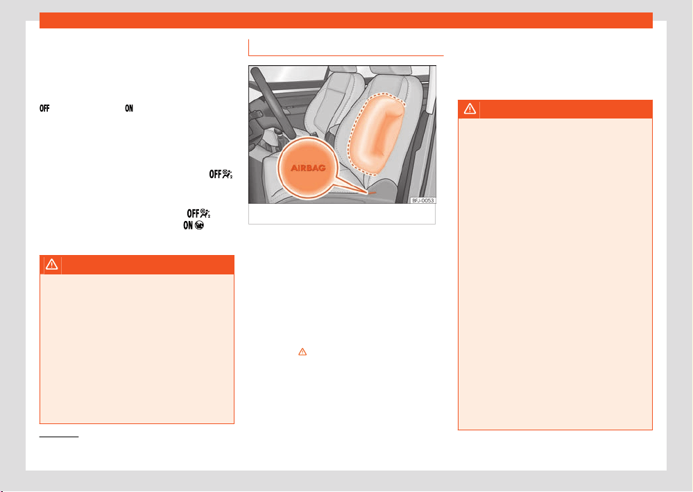
Safety
53
Airbag system
1)
Depending on the equipment, also in the event of a rollover.
●
Insert the key blade into the slot provided
in the fr
ont passenger airbag disconnection
switch ›››Fig.32. About 3/4 of the key should
enter; this is as far as it will go.
●
Turn the key gently to change its position to
(deactivate) or to (activate). If you have
dicult
y, ensure that you have inserted the key
as far as it will go.
●
Close the front passenger door.
●
When deactivating the airbag, switch the ig-
nition on and check that the control lamp
remains lit ›››Fig.33.
●
When reactivating the airbag, check that
when the ignition is s
witched on, the
con-
tr
ol lamp does not light up and the
lamp
lights up f
or 60 seconds and then turns o.
WARNING
●
The driver of the vehicle is responsible for
disabling or s
witching on the airbag.
●
Always switch o the ignition before disa-
bling the front passenger airbag! Failure to
do so could result in a fault in the airbag de-
activation system.
●
Never leave the key in the airbag disabling
switch as it could get damaged or enable or
disable the airbag during driving.
●
If for any reason an airbag is deactivated,
reactivate it as soon as possible so that it
can fulfil its protective function.
Side airbags
Fig.34 Side airbag in driv
er's seat.
The side airbags are located in the front seat
backr
ests ›››Fig.34.
Its location is marked with the word “AIRBAG” on
the upper part of the back of the seats or on the
lower coverings with the word AIRBAG in relief.
In conjunction with the seat belts, the side air-
bag system provides additional protection for
the upper body in the event of a severe side
collision ›››
.
1)
In a side collision, the side airbags r
educe the
risk of injury to passengers to the areas of the
body facing the impact. In addition to their nor-
mal protection, the seat belts also hold the
passengers in the event of a side collision; this
is ho
w these airbags provide maximum protec-
tion.
WARNING
●
If you do not wear a seat belt, if you lean
f
orward, or are not seated correctly while the
vehicle is in motion, you are at a greater risk
of injury if the side airbag system is triggered
in an accident.
●
In order for the side airbags to provide
their maximum protection, the prescribed sit-
ting position must always be maintained with
seat belts fastened while travelling.
●
In a side-on collision the side airbags will
not work if the sensors do not correctly
measure the pressure increase on the inte-
rior of the doors, due to air escaping through
the areas with holes or openings in the door
panel.
●
Never drive if the interior door panels have
been removed or if the panels have not been
correctly fitted.
●
Occupants of the outer seats must never
carry any objects or pets in the deployment
space between them and the airbags, or al-
low children or other passengers to travel
in this position. It is also important not to at-
tach any accessories (such as cup holders)
to the doors. This would impair the protection
oered by the side airbags.
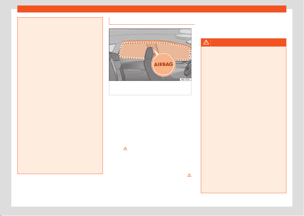
54
Safety
●
The built-in coat hooks should be used only
f
or lightweight clothing. Do not leave any
heavy or sharp-edged objects in the pock-
ets.
●
Great forces, such as hard blows or kicks,
must not be exerted upon the backrest bol-
ster because the system may be damaged.
In this case, the side airbags would not be
triggered.
●
Under no circumstances should protective
covers be fitted over seats with side airbags
unless the covers have been approved for
use in your vehicle. Because the airbag de-
ploys from the side of the backrest, the use
of conventional seat covers would obstruct
the side airbag, seriously reducing the air-
bag's eectiveness.
●
Any damage to the original seat upholstery
or around the seams of the side airbag units
must be repaired immediately by a special-
ised workshop.
●
The airbags provide protection for just one
accident; replace them once they have de-
ployed.
●
Any work on the side airbag system or re-
moval and installation of the airbag compo-
nents for other repairs (such as removal of
the front seat) should only be performed by a
specialised workshop. Otherwise, faults may
occur during the airbag system operation.
Head-protection airbags
Fig.35 L
ocation and deployment area of the
head-protection airbag.
Head-protection airbags are on both sides of
the passenger compartment, abo
ve the doors
›››Fig.35 and their location is indicated with
the word “AIRBAG”.
In conjunction with the seat belts, the head-
protection airbag system gives the vehicle oc-
cupants additional protection for the head and
upper body in the event of a severe side colli-
sion ›››
.
The fr
amed area is covered by the head-pro-
tection airbag when it is deployed (deployment
area) ›››Fig.35. Therefore, objects should
never be placed or mounted in this area ›››
.
In the e
vent of a side collision the curtain airbag
is triggered on the impact side of the vehicle.
The head-protection airbags reduce the risk of
injury t
o passengers in the front and rear side
seats facing the impact.
WARNING
●
In order for the head-protection airbags
t
o provide their maximum protection, the pre-
scribed sitting position must always be main-
tained with seat belts fastened while travel-
ling.
●
For safety reasons, the curtain airbag must
be disabled in those vehicles fitted with a
screen dividing the interior of the vehicle.
See your technical service to make this ad-
justment.
●
There must be no other persons, animals
or objects between the occupants of the
outer seats and the deployment space of the
head-protection airbags so that the head-
protection airbag can deploy completely
without restriction and provide the greatest
possible protection. Therefore, sun blinds
which have not been expressly approved for
use in your vehicle may not be attached to
the side windows.
●
The built-in coat hooks should be used only
for lightweight clothing. Do not leave any
heavy or sharp-edged objects in the pock-
ets. Please, do not hang the clothes on coat
hangers.
●
The airbags provide protection for just one
accident; replace them once they have de-
ployed.
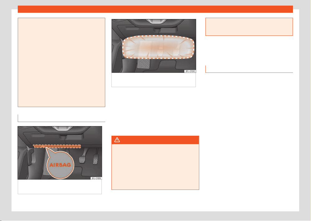
Safety
55
Transporting children safely
●
Any work on the head-protection airbag
syst
em or removal and installation of the air-
bag components for other repairs (such as
removal of the roof lining) should only be
performed by a specialised workshop. Oth-
erwise, faults may occur during the airbag
system operation.
●
The side and head airbags are managed
through sensors located in the interior of the
front doors. To ensure the correct operation
of the side and curtain airbags neither the
doors nor the door panels should be modi-
fied in any way (e.g. fitting loudspeakers). If
the front door is damaged, the airbag system
may not work correctly. All work carried out
on the front door must be done in a special-
ised workshop.
Knee airbag
Fig.36 On the driv
er side: location of airbag
for knees.
Fig.37 On the driv
er side: action radius of
airbag for knees.
The knee airbag is located on the driver side
bel
ow the dash panel ›››Fig.36. Airbags are
identified by the word “AIRBAG”.
The framed area (deployment area) ›››Fig.37
is covered by the knee airbag when it is de-
ployed. Objects should never be placed or
mounted in this area.
WARNING
●
The knee airbag is deployed in front of the
driv
er's knees. Always keep the deployment
areas of the knee airbags free.
●
Never not fix objects to the cover or in the
deployment area of the knee airbag.
●
Adjust the driver's seat so that there is a
distance of at least 10 cm (4 inches) between
your knees and the location of the this air-
bag. If your physical constitution prevents
you from meeting these requirements, make
sure you contact a specialised workshop.
Transporting children
safely
Introduction
For safety reasons, as we have learned from
accident statistics, we recommend that chil-
dren under 12 years of age travel in the rear
seats. Depending on their age, height and
weight, children travelling in rear seats must use
a child seat or a seat belt. For safety reasons,
the child seat should be installed in the rear
seat, behind the front passenger seat or in the
centre back seat.
The laws of physics involved and the forces
acting in a collision apply also to children
›››page43. But unlike adults, children do not
have fully developed muscle and bone struc-
tures. This means that children are subject to a
greater risk of injury.
To reduce the risk of injuries, children must al-
ways use special child restraint systems when
travelling in the vehicle.
We recommend the use of child safety
products from the Original Accessories Pro-
gramme, which includes systems for all ages
made by “Peke” (not for all countries) (see
www.seat.com).
56
Safety
These systems have been especially designed
and appr
oved, complying with the ECE-R44.
regulation.
SEAT recommends securing the child seats
shown on the website as described below:
●
Child seats in the opposite direction of travel
(group 0+): ISOFIX and support peg (ROMER
BABY SAFE PLUS SHR II + ISOFIX BASE / PEKE G0
I-SIZE + I-SIZE BASE).
●
Child seats in the direction of travel (group
1): ISOFIX and Top Tether (ROMER DUO PLUS +
TOP TETHER / PEKE G1 TRIFIX I-SIZE).
●
Forward facing child seats (group 2): safety
belt and ISOFIX (ROMER BRITAX KIDFIX2 S).
●
Child seats directed towards the front of the
vehicle (group 3): safety belt (TAKATA MAXI).
Follow the manufacturer's instructions and ob-
serve any statutory requirements when instal-
ling and using child seats. Always read and
note ›››page57.
We recommend you always carry the man-
ufacturer's Child Seat Instruction Manual to-
gether with the on-board documentation.
Child seats group classification
Fig.38 Ex
amples of child seats.
Use only child seats that are ocially appr
oved
and suitable for the child.
These seats are subject to the ECE-R44 or
ECE-R129 standards. ECE-R stands for: Eco-
nomic Commission for Europe Regulation.
Child seats by weight group
The child seats are grouped into 5 categories:
Age group Weight of the child
Group 0 Up to 10 kg
Group 0+ Up to 13 kg
Group 1 From 9 to 18 kg
Group 2 From 15 to 25 kg
Group 3 From 22 to 36 kg
Child seats that have been tested and ap-
pr
oved under the ECE R44 or ECE-R129 stand-
ards bear the ECE-R44 or ECE-R129 test marks
on the seat (the letter E in a circle with the test
number below it).
Follow the manufacturer's instructions and ob-
serve any statutory requirements when instal-
ling and using child seats.
We recommend you to always include the
manufacturer's Child Seat Instruction Manual
together with the on-board documentation.
SEAT recommends you use child seats from the
Original Accessories Catalogue. These child
seats have been designed and tested for use in
our vehicles. You can find the right child seat for
your model and age group at our dealers.
Child seats by approval category
Child seats may have the approval category
of universal, semi-universal, vehicle specific (all
according to the ECE-R44 standard) or i-Size
(according to the ECE-R129 standard).
●
Universal: child seats with universal approval
can be installed in all vehicles. There is no need
to consult any list of models. In the case of
universal approval for ISOFIX, the child seat is
additionally provided with a Top Tether belt.
●
Semi-universal: semi-universal approval, in
addition to the standard requirements of univer-
sal approval, requires safety devices to lock
the child seat, which require additional test-
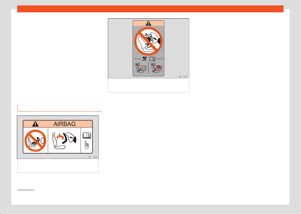
Safety
57
Transporting children safely
1)
Compliance with current national legislation and the manufacturer's instructions is required when using or installing child seats.
ing. Child seats with semi-universal approval
include a list of v
ehicle models for which they
can be installed.
●
Vehicle-specific: vehicle-specific approval
requires a dynamic test of the child seat for
each vehicle model separately. Child seats
with vehicle-specific approval also include a list
of vehicle models for which they can be instal-
led.
●
i-Size: child seats with i-Size approval must
meet the requirements prescribed in the ECE-
R 129 standard in relation to installation and
safety. Child seat manufacturers can tell you
which seats have i-Size approval for this vehi-
cle.
Fitting and using child seats
Fig.39 Airbag stick
er: on the passenger side
sunshade blind.
Fig.40 Airbag stick
er: on the rear frame of the
passenger side door.
Warnings about fitting a chil
d seat
Take the following general warnings into ac-
count if you are going to fit a child seat. They
are valid for all child seats regardless of their
attachment system.
●
Please read and follow the child seat manu-
facturer's operating instructions.
●
The child seat should preferably be fitted to
the rear seat behind the front passenger seat
so that the child can exit the vehicle on the
pavement side.
●
Set the height of the seat belt such that it
adapts to the child seat naturally, without twist-
ing. The lowest position of the seat belt height
regulator must be used with rear-facing child
seats.
●
To correctly use a child seat in the back, the
front backrest must be adjusted so that there
is no contact with the child seat in the back in
the case that it goes opposite to the direction
of the car. In the case of front facing restraint
systems, the front backrest must be adjusted so
that there is no contact with the child's feet.
●
For a correct assembly of the child's seat on
the rear seats, adjust or dismount the headrest,
in order to prevent contact with the seat.
●
If a semi-universal type chair is to be installed,
in which the method of attachment to the car
is through the seat belt and support bracket,
it should never be installed in the central rear
seat as the ground clearance is lower than in
other places and the support bracket will not
allow the seat to remain suciently stable.
●
When fitting a child seat on the front passen-
ger seat, the seat must be moved backwards
as far as possible and placed in the highest
position. The backrest must also be put in a
vertical position
1)
.
Important information about the front pas-
senger front airbag
A sticker with important information about the
passenger airbag is located on the passenger's
sunshade blind and/or on the passenger side
door frame ›››Fig.39.
Read and always observe the safety informa-
tion included in the following chapters:
58
Safety
●
Safety distance with respect to the passen-
ger airbag ›››page49.
●
Objects between the passenger and the pas-
senger side airbag ›››
in Fr
ont airbags on
page52.
The passenger side front airbag, when enabled,
is a serious risk for a child that is facing back-
ward since the airbag can strike the seat with
such force that it can cause serious or fatal inju-
ries. Children up to 12 years old should always
travel on the rear seat.
Therefore we strongly recommend you to trans-
port children on the rear seats. This is the safest
location in the vehicle. Alternatively, the front
passenger airbag can be disabled with a key-
operated switch ›››page52. When transport-
ing children, use a child seat suitable for the
age and size of each child ›››page56.
WARNING
●
If a child seat is secured to the front pas-
senger seat, the risk t
o the child of sustaining
critical or fatal injuries in the event of an ac-
cident increases.
●
An inflating front passenger airbag can
strike the rear-facing child seat and project
it with great force against the door, the roof
or the backrest.
●
Never install a child seat facing back-
wards on the front passenger seat unless
the front passenger front airbag has been
disabled. Risk of potentially fatal injuries to
the child! However, if necessary, the front
passenger front airbag must be deactivated
›››page52 . If the passenger seat has
a height adjustment option, move it to the
highest, most upright position. If you have a
fixed seat, do not install any child restraint
system in this location.
●
For those vehicles that do not include a key
lock switch to deactivate the airbag, the ve-
hicle must be taken to a technical service. Do
not forget to reconnect the airbag when an
adult wants to sit in the front passenger seat.
●
Never allow a child to be transported in a
vehicle without being properly secured, or
to stand up or kneel on a seat while travel-
ling. In an accident, the child could be flung
through the vehicle, causing possibly fatal
injuries to themselves and to the other vehi-
cle occupants.
●
Never leave a child alone in the child seat
or in the vehicle.
●
Children who are less than 1.50 m tall must
not wear a normal seat belt without a child
seat, as this could cause injuries to the ab-
dominal and neck areas during a sudden
braking manoeuvre or in an accident.
●
When a child seat is mounted in the rear
seats, the door child-proof lock should be
activated ›››page94.
Attachment systems
Depending on the country, dierent attach-
ment systems are used for safely installing child
seats.
Attachment systems overview
●
ISOFIX: ISOFIX is a standardised attachment
system allowing quick and safe attachment of
child seats in the vehicle. ISOFIX attachment es-
tablishes a rigid connection between the child
seat and the car body.
The child seat has two rigid attachment clips,
called connectors. These connectors are fit-
ted into the ISOFIX attachment rings found be-
tween the seat cushion and the backrest of
the vehicle's back seat (on the sides). ISOFIX
attachment systems are used mainly in Europe
›››page59. If necessary, ISOFIX attachment
may have to be supplemented with a Top
Tether belt or a support bracket.
●
Automatic three-point seat belt. Whenever
possible, it is preferable to attach the child
seats with the ISOFIX system rather than at-
taching them with an automatic three-point
seat belt ›››page63.
Additional attachment:
●
Top Tether: the Top Tether belt is guided over
the back of the rear seat and attached to an
anchor point with a hook. Anchor points are lo-
cated at the back of the rear seat backrest on

Safety
59
Transporting children safely
the luggage compartment side ›››page62.
The rings f
or retaining the Top Tether belt are
marked with an anchor symbol.
●
Support bracket: some child seats rest on
the floor of the vehicle with a support bracket.
The support bracket prevents the child seat
from tipping forward in the event of impact.
Child seats fitted with a support bracket should
only be used in the passenger seat and side
rear seats ›››
. For the assembly of this type
of seat you shoul
d also consult the list of ap-
proved vehicles for this assembly, available in
the instructions for child restraint systems.
Recommended systems for attaching child
seats
SEAT recommends attaching child seats as fol-
lows:
●
Baby carriers or child seats in the opposite
direction of travel: ISOFIX and support bracket
or i-Size.
●
Child seats in the direction of travel: ISOFIX
and Top Tether.
WARNING
Incorrect use of the support bracket can
cause serious or f
atal injury.
●
Make sure the support bracket is correctly
and safely installed.
●
When the base of the child seat is sup-
porting the child’s weight, the support foot
should not hang in the air or be supplemen-
ted with objects. In addition, make sure that
the base of the child seat is always suppor-
ted by the surface of the vehicle's seat. The
support leg of the child seat should not raise
the base of the child seat o the surface of
the vehicle's seat.
Securing the child seat with the ISO-
FIX or i-Size system
The marking of ISOFIX or i-Size anchor points
depends on the equipment and the country in
question.
See the following tables to understand the
compatibility of the ISOFIX/i-Size systems in the
vehicle:

60
Safety
Vehicle ISOFIX positions
Weight group Size class
a)
Electrical
equipment
Front passenger seat Second row of seats
Third row of
seats
b)
airbag enabled airbag disabled side centre
Baby carrier
F ISO/L1 X X X X X
G ISO/L2 X X X X X
Group 0 to 10 kg E ISO/R1 X IL IL X X
Group 0+ to 13 kg
E ISO/R1 X IL IL X X
D ISO/R2 X IL IL X X
C SO/R3 X IL IL X X
Group I 9 to 18 kg
D ISO/R2 X IL IL X X
C ISO/R3 X IL IL X X
B ISO/F2 X IL, IUF IL, IUF X X
B1 ISO/F2X X IL, IUF IL, IUF X X
A ISO/F3 X IL, IUF IL, IUF X X
Group II 15 to 25 kg --- --- X IL IL X X
Group III 22 to 36 kg --- --- X IL IL X X
IUF: Suitable for forward-facing ISOFIX universal child restraint systems approved for use in this weight group.
IL
: It is suitable for certain ISOFIX child restraint systems (CRS) that can be for the specific vehicle, restricted or semi-universal categories. Take the child seat
manufacturer's vehicle list into account.
X: ISOFIX position not suitable for ISOFIX child restraint systems for this weight group or size class.
a)
The indication of class according to size corresponds to the authorised bodyweight for the child seat. In child seats with universal or semi-universal approval, the
class according to size is indicated on the ECE approval label. The indication of class according to size is stated on the corresponding child seat.
b)
Third row not available for all versions.
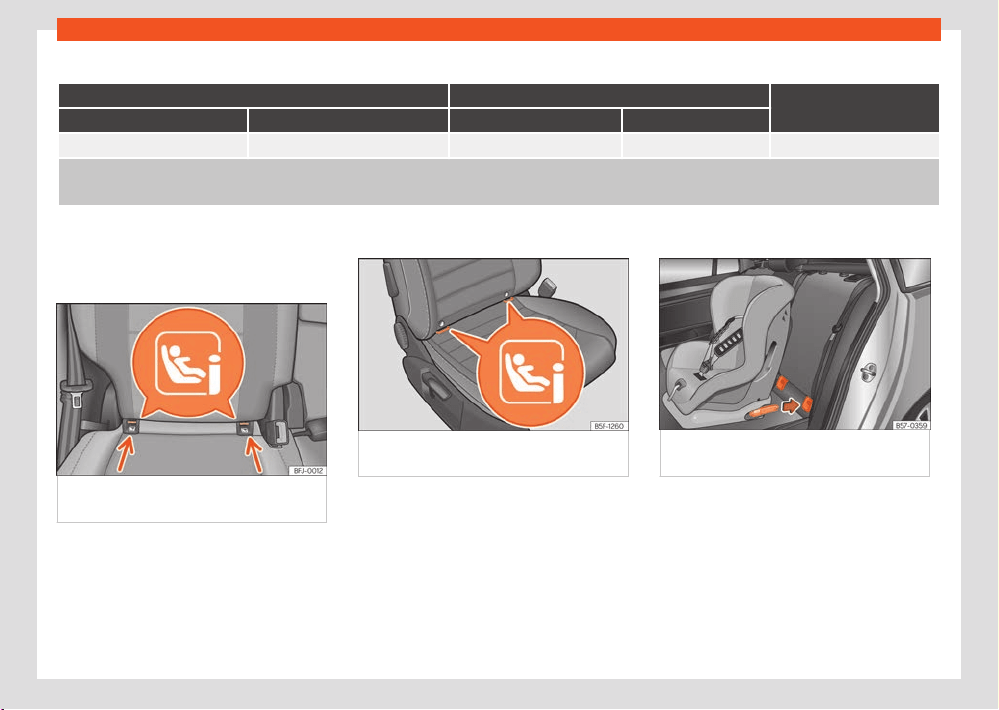
Safety
61
Transporting children safely
Vehicle i-Size positions
Front passenger seat Second row of seats
Third row of seats
a)
airbag enabled airbag disabled side centre
X i-U i-U X X
i-U: Position suitable for forward- or rear-facing i-Size child restraint systems with universal certification.
X
: Position not suitable for i-Size child restraint systems.
a)
Third row not available for all versions.
Securing the child seat with the ISOFIX or
i-Size system
Fig.41 R
ear seat: location of the ISOFIX or
i-Size securing rings.
Fig.42 Fr
ont passenger seat: location of the
i-Size fastening rings.
Fig.43 R
ear seats: fitting a child seat with the
ISOFIX system.
You must follow the child seat manufacturer's
instructions.
The l
ocation of the ISOFIX or i-Size anchor
points is indicated by a symbol ›››Fig.41 ,
›››Fig.42. In some vehicles, the rings are se-
cured to the seat frame and, in others, they are
secured to the rear floor.
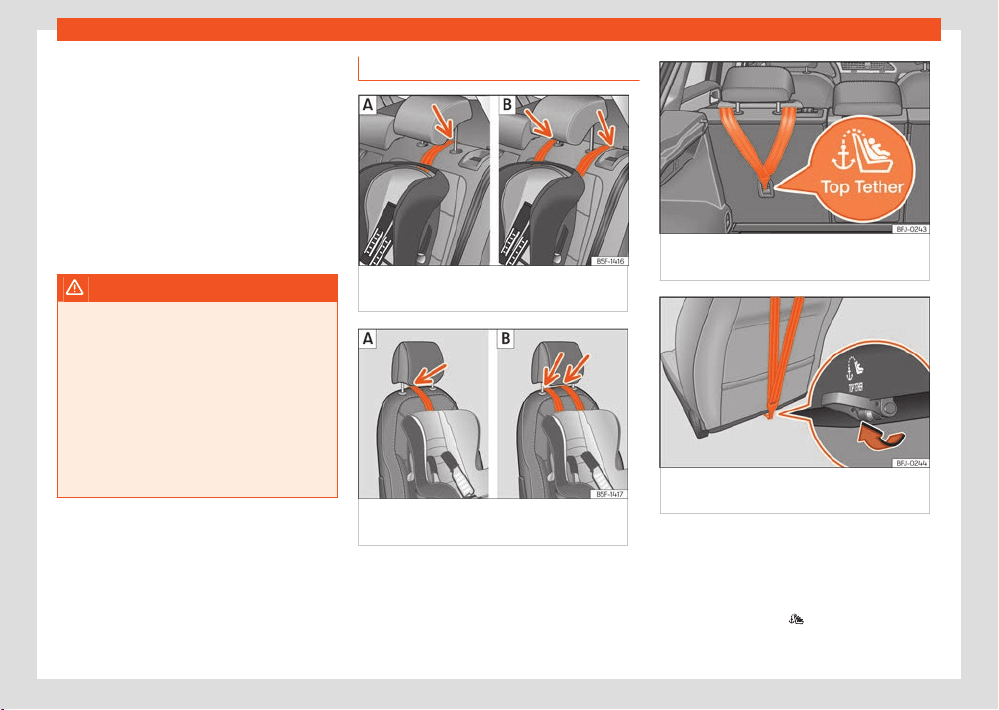
62
Safety
●
Press the child seat onto the ISOFIX or iSize
r
etaining rings until it is heard to engage se-
curely ›››Fig.43. If the child seat is equipped
with Top Tether anchor points, secure it to the
correspondent ring ›››page62. Follow the
child seat manufacturer’s instructions.
●
Pull on both sides of the child seat to ensure
that it is properly anchored.
Child seats with the ISOFIX or i-Size and Top
Tether attachment system can be purchased
from technical services.
WARNING
The securing rings are designed only for use
with ISOFIX or i-Siz
e and Top Tether system
child seats.
●
Never secure other child seats that do not
have ISOFIX, i-Size or Top Tether systems, or
safety belts or any other objects to the se-
curing rings – as this can result in potentially
fatal injuries to the child.
●
Ensure that the child seat is correctly se-
cured to the ISOFIX or i-Size rings and the Top
Tether.
Top Tether securing belts
Fig.44 R
ear seats: adjustment and assembly
according to the Top Tether belt.
Fig.45 P
assenger seat: adjustment and
assembly according to the Top Tether belt.
Fig.46 R
ear part of the second row of rear
seats: securing rings for the Top Tether strap.
Fig.47 R
ear of front passenger seat backrest:
Top Tether strap anchor.
Child seats with a Top Tether system are fitt
ed
with an additional strap for fastening to an an-
chor point in the vehicle. This anchor point is
located on the rear of the rear seat backrest
and of the front passenger seat backrest (iden-
tified with the symbol
) and provides better
r
etention.
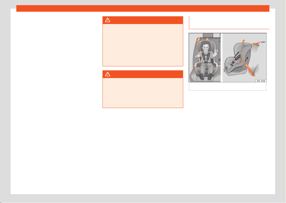
Safety
63
Transporting children safely
The objective of this system is to reduce for-
w
ard movements of the child seat in a head-on
collision, to reduce the risk of injuries that may
be caused to the child’s head by impacting
against any element of the inside of the vehicle.
Using the Top Tether in rear-facing mounted
seats
Currently, there are very few rear-facing child
safety seats that have Top Tether. Please care-
fully read and follow the seat manufacturer in-
structions to learn the proper way to install the
Top Tether strap.
Securing the retainer strap
●
Follow the manufacturer's instructions to de-
ploy the child seat Top Tether retaining strap.
●
Position the belt under the headrest (accord-
ing to the instructions of the seat itself, lift or
remove the headrest if necessary) ›››Fig.44 ,
›››Fig.45.
●
Slide the strap and secure it properly with the
anchor on the rear seat backrest ›››Fig.46 ,
›››Fig.47.
●
Firmly tighten the strap following the manu-
f
acturer's instructions.
Releasing the retaining strap
●
Loosen the strap following the manufacturer's
instructions.
●
Push the lock and release it from the anchor-
ing support.
WARNING
An undue installation of the safety seat will
incr
ease the risk of injury in the event of a
crash.
●
Never tie the retainer strap to a hook in the
luggage compartment.
●
Never secure or tie luggage or other items
to the lower anchorages (ISOFIX) or the up-
per ones (Top Tether).
WARNING
Child restraint anchors are designed to sup-
por
t the loads of properly adjusted child
restraint systems. Under no circumstances
should they be used to attach adult seat
belts, harnesses or other items or equipment
to the vehicle.
Fitting a child seat using the seat
belt
Fig.48 On r
ear seats: installing a child seat.
If you want to fit a univ
ersal approval category
(U) child seat in your vehicle, you must check
that the seat is approved for your vehicle. You
will find any necessary information on the child
seat’s orange ECE approval label. The following
table shows the dierent fitting options.
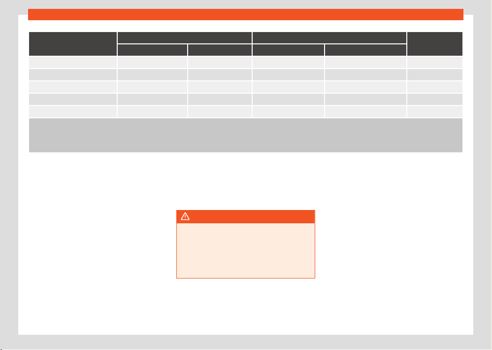
64
Safety
Weight group
Front passenger seat
a)
Second row of seats
Third row of seats
b)
Airbag enabled Airbag deactivated
c)
side centre
d)
Group 0 to 10 kg X U U U U
Group 0+ to 13 kg X U U U U
Group I 9 to 18 kg X U U U U
Group II 15 to 25 kg X UF UF UF UF
Group III 22 to 36 kg X UF UF UF UF
X: Not compatible for the installation of seats install chairs in this configur
ation.
U: Suitable for universal restraint systems for use in this weight group.
UF: Acceptable for front-facing universal-category child restraint systems approved for this mass group.
a)
Compliance with current national legislation and the manufacturer's instructions is required when using or installing child seats.
b)
Third row not available for all versions.
c)
Seats without height adjustment should be placed in their rearmost position. Seats with height adjustment should be placed in their rearmost and highest
position.
d)
For semi-universal chairs where the securing system is the car safety belt and the support bracket, do not use them in the centre rear seat or the third row.
Fitting a child seat using the seat belt
●
Set the height of the seat belt such that it
adapts to the child seat naturally, without twist-
ing. The lowest position of the seat belt height
regulator must be used with rear-facing child
seats.
●
Put the seat belt in place and pass it through
the child seat according to the instructions of
the child seat manufacturer.
●
Make sure that the seat belt is not twisted.
●
Insert the latch plate into the seat's buckle
until you hear the engagement click.
WARNING
When travelling, children must be secured in
the v
ehicle with a restraint system suitable
for age, weight and size.
●
Always read and observe information and
warnings concerning the use of child seats
›››page57.
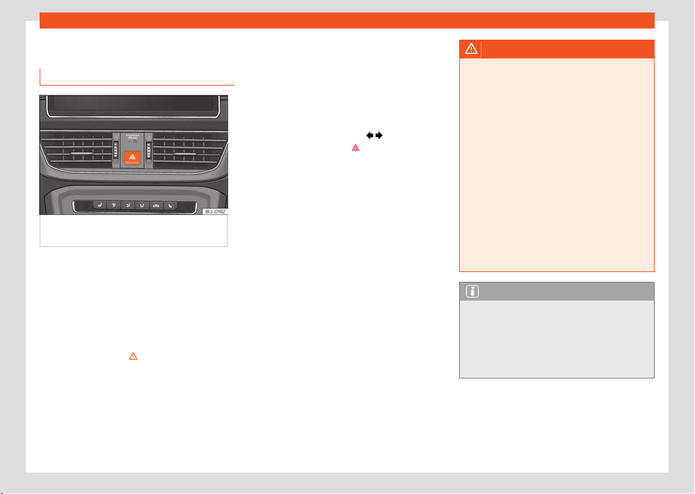
Safety
65
In case of emergency
In case of emergency
Haz
ard warning lights
Fig.49 Dashboar
d: switch for hazard warning
lights.
The hazard warning lights are used to draw the
att
ention of other road users to your vehicle in
emergencies.
If your vehicle is stationary:
1. Park the vehicle at a safe distance from
road trac.
2. Press the button to switch on the hazard
warning lights ››› .
3. Apply the electronic parking brake.
4. Stop the engine.
5. Engage 1st gear in vehicles with a manual
gearbox, or set the gear selector to the
P position in vehicles with automatic trans-
mission.
6. Follow the legal provisions of each country
(r
eflective vest, warning triangles, light bea-
con, etc.).
7. Always carry the key with you when leaving
the vehicle.
All turn signals flash simultaneously when the
hazard warning lights are switched on. The two
turn signal turn signal lamps
and the turn
signal l
amp in the switch
will flash at the
same time
. The simultaneous hazard warning
lights also work when the ignition is switched
o.
While the hazard warning lights are on, you can
signal a direction or lane change, e.g. during
towing, by operating the turn signal lever. The
hazard warning lights remain switched o dur-
ing this time.
Emergency braking warning
If the vehicle brakes suddenly and continuously
at a speed of more than 80 km/h (50 mph), the
brake light flashes several times per second to
warn the vehicles driving behind. If you continue
braking, the hazard warning lights will come
on automatically when the vehicle comes to a
standstill. They switch o automatically when
the vehicle starts to move again.
WARNING
●
The risk of an accident increases if your
v
ehicle breaks down. Always use the hazard
warning lights and a warning triangle (or
light beacon, depending on the country) to
draw the attention of other road users to
your stationary vehicle.
●
Never leave anybody inside the vehicle,
particularly children or anybody who may
need help. This is especially important when
the doors are locked. Individuals locked in
the vehicle can be exposed to very high or
very low temperatures.
●
Due to the high temperatures that the cat-
alytic converter can reach, never park in
an area where the catalytic converter could
come into contact with highly inflammable
materials, for example dry grass or spilt pet-
rol. This could start a fire.
Note
●
The 12-volt vehicle battery will run down
if the haz
ard warning lights are left on for a
long time (even if the ignition is switched o).
●
The use of the hazard warning lights de-
scribed here is subject to the relevant statu-
tory requirements.
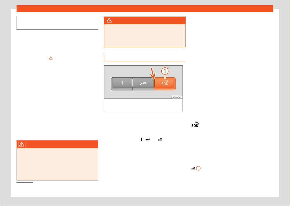
66
Safety
1)
Only available in certain countries.
Behaviour in the event of an accident
or fir
e
Actions to take in the event of a fire or acci-
dent
For your own safety and that of other passen-
gers, the following points should be observed in
the order given ›››
:
●
Switch o the engine
.
●
If possible, switch on the hazard warning
lights ›››page65.
●
Follow the legal provisions of each country
(reflective vest, warning triangles, light beacon,
etc.).
●
If necessary, get any people out of the haz-
ard area and apply first aid.
●
Notify the emergency services.
●
Wait at a safe distance from the scene of the
accident for the emergency services to arrive.
●
In case of fire, do not attempt to extinguish
the fire yourself or remain near the vehicle.
WARNING
For your own safety, do not ignore this impor-
t
ant check list, otherwise accidents and seri-
ous injuries could occur.
●
Always complete the operations on the
check list and always bear in mind the gen-
eral safety measures.
WARNING
In the event of fir
e, an explosion may occur
and substances harmful to health may be re-
leased, which can cause serious injury.
●
Never stay near the burning vehicle.
Emergency call service
Fig.50 On the r
oof console: controls for voice
services
Depending on the equipment, an emergency
call syst
em may be located on the roof con-
sole.
The following voice services can be run by
pressing the buttons
, and ›››Fig.50:
●
information call
●
assistance call
●
emergency call service.
A built
-in control unit establishes the connec-
tion.
When a voice service is activated, a connection
is est
ablished with a phone line.
Control lamp
There is a control lamp on the control
›››Fig.50 (arrow). It shows the following sta-
tuses:
●
O: the eCall service is not available.
●
Flashes in red, approx. 20 seconds after
swing on the ignition: the eCall service is de-
activated.
●
Lights up red: system failure. The eCall serv-
ice is available with certain restrictions. SEAT
suggests going to a specialised workshop.
●
Lights up green: the eCall service is availa-
ble. The system works correctly.
●
Flashes green: There is an ongoing voice
connection.
Emergency call service
1)
The aut
omatic emergency call is only activated
if the ignition is switched on.
If the airbags or, if applicable, the seatbelt ten-
sioners are triggered, a connection is automat-
ically established with the emergency coordi-
nation centre. The automatic emergency call
cannot be interrupted by pressing the button
1
.

Safety
67
In case of emergency
If the emergency coordination centre's ques-
tions ar
e not answered, the corresponding as-
sistance measures are implemented.
If the call is public, the person on the other end
of the line uses the language of the country in
which you are located.
If the call is private, the person on the other end
of the line will assist you in the language you
have configured in the Infotainment system. If
the configured language is not available, Eng-
lish will be used.
Starting an emergency call manually
●
Press and hold the emergency call button
for a few seconds
1
. The emergency call is
activ
ated and a voice connection is established
with the emergency coordination centre.
If you press the emergency call button inadver-
tently, hang up the call immediately:
●
Press the emergency call button again until
the control light stays green.
Integrated battery
The integrated battery ensures that the emer-
gency call system (eCall) remains available for
some time even if the 12-volt battery has been
disconnected or has failed.
If the integrated battery discharges or is de-
fective, a message stating this is displayed on
the instrument cluster display. Go to a special-
ised workshop and ask for the battery to be
replaced.
EDR data transmission ›››page375
When an emergency call is made, the legally
required data is transmitted to the emergency
coordination centre so that the necessary as-
sistance measures can be determined.
Vehicle location data is continuously overwrit-
ten. This means that the vehicle is not subject to
permanent monitoring.
The data related to the emergency call is only
processed to ensure the correct operation of
the emergency call system (eCall). The system
will automatically delete the data related to the
call a few hours after the call is activated.
The sent data includes:
●
The vehicle's current position at the time the
emergency call is activated.
●
Vehicle identification number (VIN)
●
Type of vehicle and type of drive.
●
Type of activation (automatic or manual).
●
Type of call.
●
Direction in which the vehicle was travelling
at the time the emergency call was activated.
●
Moment of the collision.
●
Estimated number of vehicle occupants.
Diversion to 112 emergency number
In some situations where the emergency call
service is limited or cannot be carried out, an
emergency call is made to 112.
The following conditions may cause the emer-
gency call service to function in a limited man-
ner or the call to be diverted to the 112 emer-
gency number:
●
The emergency call is made from an area
with weak or no mobile and GPS signal, as well
as e.g. tunnels, between very tall buildings, ga-
rages, underground walkways, mountains and
valleys.
●
In areas with sucient mobile telephone and
GPS coverage, the mobile telephone network
of the telecommunications operator in question
may not be available.
●
In some countries, the emergency call serv-
ice may not be available due to legal reasons.
There is no valid license for the use of the emer-
gency call service.
●
The components of the vehicle required for
the emergency phone call are damaged or do
not get enough power.

68
Safety
1)
Only available in certain countries.
●
In some countries, the emergency call service
may not be av
ailable and depending on the
location of the vehicle, the control lamp LEDs,
and even the operation of the dierent types of
calls, could have a specific behaviour.
Assistance call
1)
With the br
eakdown call you can directly re-
quest specialised help in the event of a break-
down.
Parallel to the voice call, some vehicle data is
transmitted, e.g. your current location.
Information call
1)
With a inf
ormation call, a call is placed to the
customer care service of SEAT.S.A.
Note
●
Breakdown service and information calls
can incur an additional cost on your t
ele-
phone bill.
●
The operation of the eCall system, which is
required by law, may be limited if an infotain-
ment system is retrofitted.
High-voltage battery
69
Safety instructions
High-voltage battery
Saf
ety instructions
Introduction
Valid for: hybrid vehicles
WARNING
The vehicle’s high-voltage network and the
high-v
oltage battery are hazardous and can
cause burns and other injuries, including fa-
tal electric shocks.
●
It should always be assumed that the high-
voltage battery is fully charged and that all
of its components are live. This may also be
the case when the ignition is switched o.
●
Never touch the high-voltage cables, the
high-voltage battery or its poles, or allow
them to come into contact with jewellery or
other metal objects, especially if the high-
voltage cables, the high-voltage battery or
its poles are damaged.
●
Never take it upon yourself to perform any
type of work on the high-voltage network, on
the high-voltage cables or the high-voltage
battery.
●
Never open or perform maintenance or
repairs on components or parts of the high
voltage network, or disconnect them from
this network.
●
Never damage, modify or remove the or-
ange high v
oltage cables or disconnect them
from the high voltage network.
●
Never open, modify or remove the cover
from the high-voltage battery.
●
Work on the high-voltage system, as well
as on any systems that may be indirectly in-
fluenced by it, should only be carried out by
specialized personnel with the correspond-
ing qualifications and training.
●
Work in the immediate vicinity of high-volt-
age cables and high-voltage components
with tools that are sharp, give o shavings or
that have heat sources, such as hot air, ther-
mal bonding or welding work, may only be
performed after disconnecting the voltage.
The high voltage should only be disconnec-
ted by specialized personnel with the corre-
sponding qualifications and training.
●
All SEAT guidelines and standards must be
followed when performing any work on the
high-voltage system and the high-voltage
battery.
●
The gases that are emitted or leaked from
the high-voltage battery may be toxic or
flammable.
●
Damage to the vehicle or high voltage bat-
tery could cause an immediate or delayed
leak of toxic gases. The emitted gases could
also cause a fire. Do not inhale the gases.
●
Never touch the liquids that spill from the
high v
oltage battery and do not touch the
emitted gases, particularly if the battery is
damaged.
●
In the event of a fir
e, leave the danger area
and call the fire department.
●
Always inform the fire fighters and the
emergency service that the vehicle is fitted
with a high-voltage battery.
WARNING
If works are performed on the high-voltage
syst
em and on the high-voltage components
in an inappropriate manner, this may lead
to faults in the operation, accidents and inju-
ries.
●
Work on the high-voltage system must
only be performed by authorized specialized
services with the corresponding permit.
NOTICE
If the vehicle suers an accident or collision
with an obst
acle, the high-voltage battery
must be checked by specialized personnel
with the corresponding qualifications and
training.
NOTICE
If the 12-volt vehicle battery has been dis-
connect
ed, discharged or replaced, there is
a chance that the combustion engine may
not initially turn o automatically after mov-
ing o. If this situation lasts for several days,
contact a qualified specialized workshop.
SEAT recommends visiting a SEAT partner for
this.
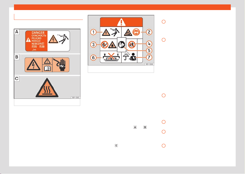
70
High-voltage battery
1
2
3
4
5
6
High voltage warning lettering
V
alid for: hybrid vehicles
Fig.51 W
arning lettering.
Fig.52 High-v
oltage battery warning lettering.
Warning lettering on the vehicle
The f
ollowing parts of the vehicle can be
identified with the depicted warning lettering
›››Fig.51, ›››Fig.52:
●
Covers and lids behind which live high-volt-
age components are located.
●
All the high-voltage components, including
the high-voltage battery.
●
Under the front bonnet.
The warning lettering ›››Fig.51
and indi-
cat
e high electrical voltage.
The components of the high voltage system
can become very hot and should not be
touched ›››Fig.51
.
›››Fig.52
High voltage can cause serious injury or
e
ven death. Never touch the battery poles
with bare fingers, tools, jewellery or other
metal objects.
The high-voltage battery contains hazard-
ous liquid and solid substances. Emitted
gases can cause severe burns and blind-
ness. Suitable eye protection and protec-
tive clothing must always be worn when
working on the high voltage battery to pre-
vent battery fluid coming into contact with
the skin and eyes. If the battery fluid comes
into contact with the skin or eyes, the af-
fected areas should be rinsed with clean
running water for at least 15 minutes, and
then a doctor should be consulted immedi-
ately.
The high-voltage battery may burn. The
high-voltage battery should never be ex-
posed to fire, sparks or naked flame. The
high voltage battery must always be han-
dled with care to avoid damage and fluid
leakages.
The high-voltage battery should always be
kept out of the reach of children.
You will find further information and warn-
ings in the usage instructions and workshop
documentation.
Incorrect handling of the high-voltage bat-
tery can cause serious injuries or death.
Never disassemble the high voltage battery
or remove its cover.
High-voltage battery
71
Charging the high-voltage battery
7
Maintenance work on the high-voltage
batt
ery must only be performed by spe-
cialized personnel with the corresponding
qualifications and training. Never modify
the high-voltage battery. When the high-
voltage battery is open, ensure it does not
come into contact with water or other liq-
uids. Liquids may cause short circuits, elec-
trical shocks and burns.
Conservation of the high-
voltage battery
Conservation instructions
Valid for: hybrid vehicles
Reliability and capacity of the high-voltage
battery
In principle, lithium ion batteries are subject to
ageing and wear and tear throughout their use-
ful life due to their physical and chemical char-
acteristics. Correct handling of the high-volt-
age battery makes an essential contribution to
keeping it in a reliable state in the long term
and to achieving high battery capacity and
range. Therefore, it is extremely important to re-
spect the following conservation instructions for
the high voltage battery. These maintenance
instructions are essential for maintaining the ve-
hicle's value over time.
Please also observe the applicable SEAT war-
ranty conditions for the high-voltage battery.
Conservation instructions
●
If possible, charge the high-voltage battery
when a low charge level is displayed on the
instrument cluster, or when the electric range is
low ›››page19.
●
It is advisable to not charging the high-volt-
age battery when only a short trip has been
made in full electric mode.
●
As much as possible avoid fully discharging
the high-voltage battery, such as by leaving
the vehicle parked for a prolonged time with a
low load level. The charge level must not drop
below 20 % for long periods of time ›››
.
●
When the high-voltage battery has been
char
ged to 100 %, start driving immediately if
possible.
Vehicle parking times
●
If there is a frost, do not park the vehicle for
several hours with a charge level of lower than
40% ›››
.
●
If you plan to leave your vehicle stationary for
pr
olonged periods of time, park with a charge
level of at least 30 %. This situation occurs, for
example, when you leave your vehicle at the
airport before a trip.
●
Do not expose the vehicle to outside temper-
atures below -30 °C or above 60 °C for more
than 24 hours.
●
To improve comfort and performance, make
sparse use of the stationary air conditioning
(depending on the equipment), particularly in
temperatures lower than -15°C.
NOTICE
The high-voltage battery must not be used
as a st
ationary power supply. This can cause
irreversible damage to the high-voltage bat-
tery.
NOTICE
If the vehicle is parked for a long time with
the high-v
oltage battery discharged, it may
no longer be possible to charge the bat-
tery or start the vehicle. Irreversible damage
could be caused to the high voltage battery
in the long term.
●
Charge the high-voltage battery at regular
intervals.
Charging the high-voltage
battery
Introduction
Valid for: hybrid vehicles
Check that the driving mode is deactivated and
that the charging cable and infrastructure are
in perfect condition.
72
High-voltage battery
Types of charging
The f
ollowing charging types are possible for
the vehicle:
●
Charging with alternating current (AC) at a
public charging station or home wallbox (Mode
3 charging) ›››page73:
Charges at high power. The maximum achieva-
ble charging power depends on the charging
station and charging cable that is used and the
performance of the vehicle's charger.
●
Charging with alternating current (AC)
at a household socket (Mode 2 charging)
›››page73:
The electrical installation of the house must
have been checked and be in perfect working
order ›››
. You must plan for a longer charg-
ing time
, e.g. overnight.
●
Charging with direct current (DC) at a fast
charging station (Mode 4 charging):
Direct current charging is not compatible with
this vehicle.
Protection against current leakage
The vehicle is fitted with a direct current (DC)
leakage protection device. This prevents any
current leakage that may occur during charg-
ing from reaching the house's electrically in-
stallation through the charging cable.
WARNING
If the battery is charged in an inappropri-
at
e manner, if no consideration is given to
the appropriate safety measures or the high-
voltage battery is used in an inadequate
manner, this could lead to short circuits,
electrical shocks, explosions, fires, burns and
serious injuries, even death.
●
Always respect the stipulated order of the
operations to avoid the risk of suering an
electric shock or serious injuries due to the
residual energy in the charging accumulator.
●
Please observe the safety and handling
instructions of the charging cable supplied
with the vehicle ›››page78.
●
When charging, only use power sockets
that are appropriately fitted, have been
checked and are not damaged, as well as
electrical installations that are in perfect
working order. Duly qualified technicians
should check the power sockets and the
electrical installation on a regular basis.
●
Never charge the vehicle in places where
there is a danger of explosion. The com-
ponents of the charging cable can cause
sparks and, therefore, may ignite flammable
fumes or explosives.
●
Always protect the connectors from mois-
ture and from water and other fluids getting
inside directly.
●
For safety reasons, never perform other
works on the vehicle while charging.
●
Always complete the charging process be-
fore unplugging the connector from the elec-
trical network. Otherwise the charging cable
and the electrical installation may also be
damaged.
Note
●
To charge the high-voltage battery using
alt
ernating current (AC), SEAT recommends
using a home charging station (wallbox) or
another type of charging station and charg-
ing with maximum charging power. These
charging options are more ecient than us-
ing a domestic power socket.
●
Please note the technical data on your ve-
hicle's charging power. For more information,
please contact a SEAT dealer.
●
The high-voltage battery can only be
charged at charging stations that meet the
requirements of the country in questions and
at least one of the following standards:
–
IEC 61851 and IEC 62196 (Europe)
●
In the event of very low or very high tem-
peratures, it may only be possible to charge
the high-voltage battery in a limited manner.
Identification of compatible charg-
ing infrastructure
Valid for: hybrid vehicles
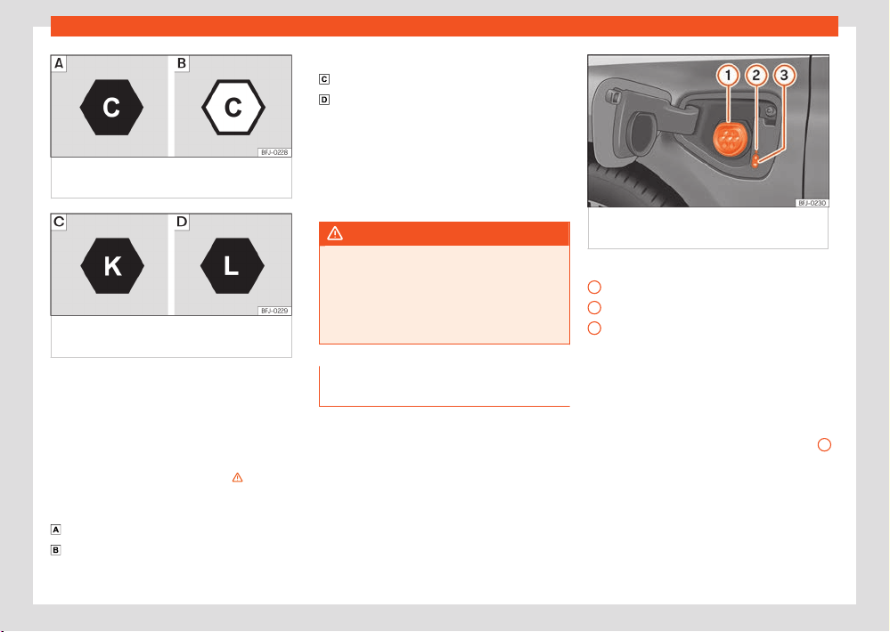
High-voltage battery
73
Charging the high-voltage battery
1
2
3
Fig.53 Identification of alt
ernating current
(AC) and type 2 connector.
Fig.54 Identification of dir
ect current (DC)
and the vehicle's CCS connector
Compatibility between vehicles and charg-
ing infr
astructure
The following indicators according to the
EN 17186 standard provide information about
whether the infrastructure's charging connec-
tors are suitable for the vehicle ›››
.
Indicat
ors ›››Fig.53
In the vehicle
At the charging station
Indicators ›››Fig.54
Voltage up to 500 volts
Voltage of up to 1000 volts.
The indicators are located on the vehicle's
charging socket, on components of the lo-
cal charging infrastructure (charging station,
socket) and on the charging cable. The indica-
tors refer to charging connection standards ac-
cording to IEC 62196.
WARNING
Charging the vehicle at unv
erified electrical
installations can cause serious injury and
damage.
●
If there is no indicator or if the charging in-
frastructure is unknown, an electrical instal-
lation expert should be consulted first.
Charging with alternating current
(AC)
Valid for: hybrid vehicles
Fig.55 Behind the batt
ery charging cover on
the front left-hand side: Charging socket
›››Fig.55
Charging process display
Char
ging socket
Charging buttons
The battery charger installed in the vehicle
converts alternating current from the public
supply into direct current.
AC charging station, wallbox or power socket
cable: The vehicle’s high-voltage battery can
be charged using alternating current (AC)
through the corresponding charging socket
2
.
Connecting the char
ging cable
●
Firstly, connect the charging cable to the
electrical socket, charging station or Wallbox.
Next, fully unwind it.
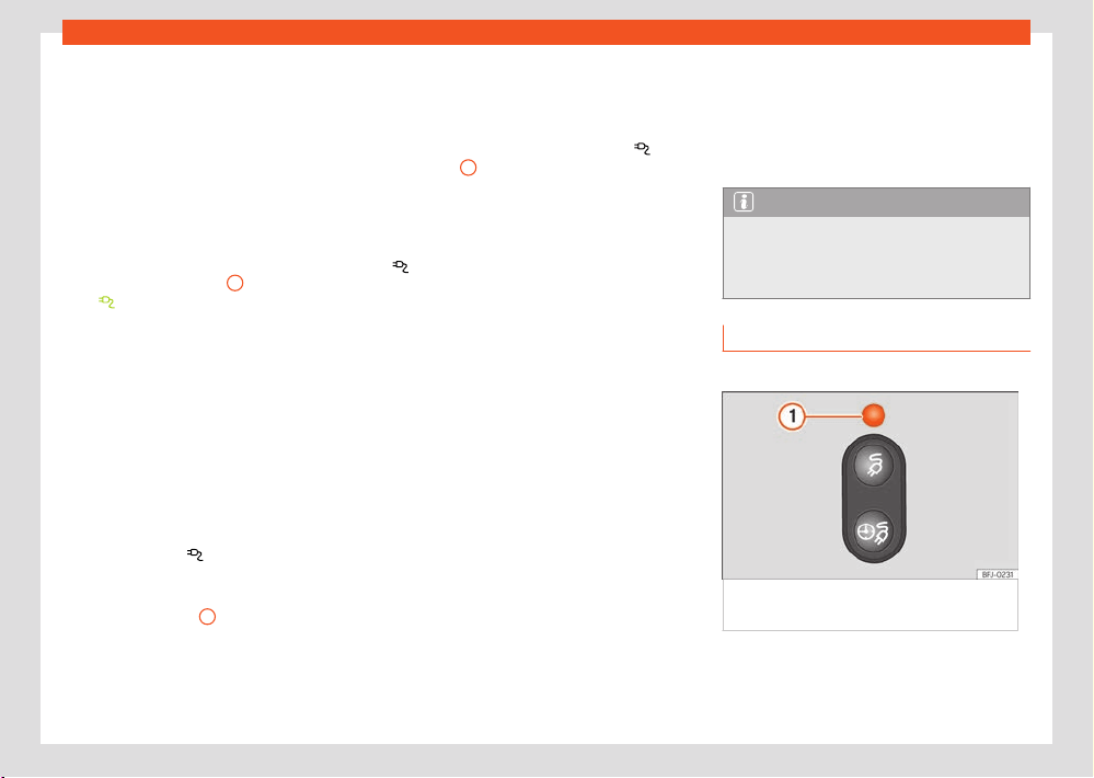
74
High-voltage battery
●
Charging cable for domestic power sock-
ets: The pr
otection device performs a self-test
›››page80.
●
With the vehicle unlocked, the battery charg-
ing cover opens when it is pressed ›››Fig.55.
●
Plug the charging connector into the charg-
ing socket. Check that the charging connector
is fully plugged in.
The connector locks automatically.
The LED (charging process display) on the
charging socket lights up
1
. The indicator
l
amp
lights up on the instrument cluster
scr
een.
You can set the charging as required in the info-
tainment system ›››page77.
Automatic start of the charging process
If programmed charging is not activated,
the charging process starts immediately
›››page77. The external charging infrastruc-
ture must be active.
During the charging
The indicator lamp
flashes gr
een on the in-
strument cluster.
The charging process indicator on the charging
socket flashes green
1
. The charging connec-
t
or is locked.
If the charging process indicator lights up red,
there is a fault ›››page74.
Interrupt the charging process
The char
ging process can be interrupted:
●
Unlock the vehicle.
●
Press the immediate charge button
›››Fig.59
1
. The charging connector remains
l
ocked.
●
Unlock the vehicle to unlock the charging
connector. The charging process can continue
by pressing the immediate charge button again
.
T
o restart the charging process just press the
function button to start the charging process.
After charging
When the high-voltage battery is fully charged,
the charging process display on the charging
socket lights up green.
●
Unlock the vehicle.
●
Unplug the charging connector from the
charging socket within 30 seconds.
●
Disconnect the charging cable from the
power supply and replace the protective cap.
●
Close the charging cover and make sure you
hear it click into place.
First charge and charging after a long time
If the high-voltage battery is new or has
not been charged for a long time, the maxi-
mum charge level of the battery can only be
reached after several charging processes. This
is for technical reasons and is not a vehicle
malfunction.
If the vehicle is not used for a long period of
time, the high-voltage battery must be charged
at least once every four months.
Note
If you leave the charging cable connected
aft
er charging, the vehicle's electrical con-
sumers will not drain the high-voltage bat-
tery.
Charging process display
Valid for: hybrid vehicles
Fig.56 Behind the batt
ery charging socket
cover: charging process indicator.
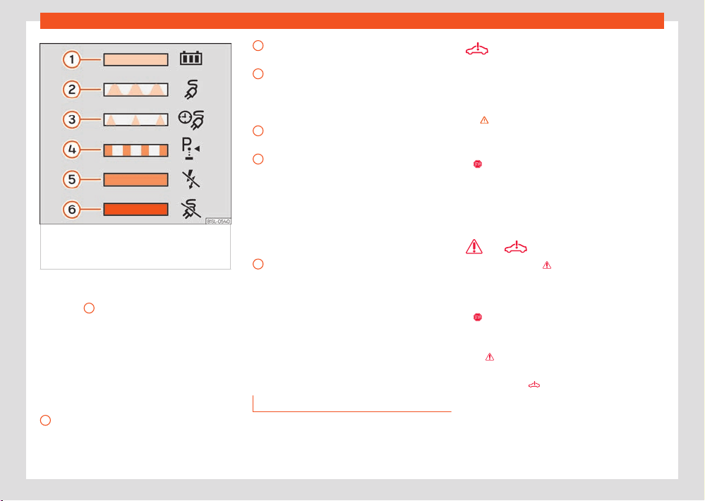
High-voltage battery
75
Charging the high-voltage battery
1
2
3
4
5
6
Fig.57 On the inside f
ace of the cover
of the battery charging socket: sticker with
information on the charging process display.
The charging process indicator is an LED
›››Fig.56
1
located on the charging socket
that sho
ws the status of the charging process.
A sticker on the battery charging cover pro-
vides information on the meaning of the LEDs
›››Fig.57.
Charging process displays:
Green LED ›››Fig.57
Always on: Charge completed success-
fully.
Flashing: The high-voltage battery is
charging.
Short flashes: Programmed charging is ac-
tive. The charging process has not yet star-
ted.
Yellow LED ›››Fig.57
Flashing: The parking lock P has not been
enabled.
Briefly lights up: The charging connector
has been plugged into the charging socket
and the vehicle has detected it.
Always on: No electrical network has been
detected. Arrange an inspection of the
power supply and network. Seek professio-
nal assistance.
Red LED ›››Fig.57
Flashing: Error in the charging system.
The charging process cannot start or has
paused.
Always on: The charging connector has
not been locked. Unplug the charging con-
nector and plug it back in to the charging
socket, making sure it is properly inserted.
If the problem persists, check the compati-
bility of the cable or ask a professional for
help.
Troubleshooting
V
alid for: hybrid vehicles
Fault in the high-voltage system
The w
arning lamp lights up red. A message is
displayed in this regard.
There is a fault in the high voltage system. The
high voltage components may be damaged
›››
.
It is not possibl
e to charge the high-voltage
battery.
●
The v
ehicle must be parked in a safe
place. Park the vehicle outdoors as soon as it is
possible and safe to do so.
●
Switch o the drive system.
●
Seek professional assistance.
and Fire risk!
The w
arning lamp
lights up red and is dis-
pl
ayed along with with a text message on the
instrument cluster accompanied by a continu-
ous audible warning.
●
St
op driving! Get out of the vehicle and
notify the fire department immediately.
●
The high voltage battery temperature is too
high
.
●
If the message is hidden, the warning lamp
r
emains visible
.
The audibl
e warning can only be turned o by
a qualified workshop. SEAT recommends that
you visit an ocial dealer.
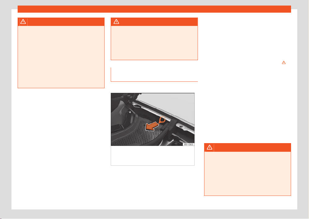
76
High-voltage battery
WARNING
If there is a risk of fir
e in the high-voltage
battery, toxic gases may escape or compo-
nents may be released from the high voltage
battery. There is a risk of serious injury, burns
or lethal electric shocks.
●
Park the vehicle safely as soon as possible
›››page66, Behaviour in the event of an
accident or fire.
●
Get out of the vehicle and keep a safe dis-
tance away from it.
●
Call the fire department immediately.
The charging process is not possible or has
been paused
The charging process indicator located next to
the charging socket lights up red.
Before visiting a specialist workshop, you can
try the following solutions:
●
Plug the charging cable back in.
●
Check that the charging settings are as de-
sired: “immediate” or “programmed”.
●
Check that the charging connector is plug-
ged in correctly.
●
Check if a fault is displayed on the charging
station or, depending on the equipment, on the
charging cable protection device.
If the fault cannot be rectified, contact a spe-
cialist workshop immediately.
WARNING
High-voltage components, including the bat-
t
ery and high-voltage cables, may be live
and damaged. The high voltage system volt-
age is dangerous and can cause burns, other
injuries and fatal electric shocks.
●
Do not touch the high voltage components!
Emergency release of the charging
connector
Valid for: hybrid vehicles
Fig.58 Betw
een the left wing panel and
the engine bonnet hinge: Charging connector
manual release mechanism puller.
Unlocking the charging connector
Pr
erequisites:
●
The charging connector is plugged in cor-
r
ectly ›››page72.
●
The vehicle is unlocked.
●
The charging process has ended or has
paused ›››page71.
The manual release mechanism must be used if
these prerequisites are met and it is still impos-
sible to unplug the charging connector ›››
Manual release of the charging connector
The pull
er for the manual release mechanism
is on the left hand side of the engine compart-
ment, above the charging socket ›››Fig.58.
●
Disconnect the power supply at the charging
st
ation or electrical socket.
●
Open the bonnet and make sure it is held in
place with the prop.
●
Use the wire hook in the vehicle’s toolkit to
hook the puller and pull on it.
●
Immediately unplug the charging connector.
WARNING
If the charging connector unexpectedly re-
mains l
ocked, the fault may be caused by the
vehicle or charging station.
The manual emergency release can make
live contacts accessible. In this case, touch-
ing the contacts of the charging socket may
result in burns, other injuries or a fatal elec-
tric shock.
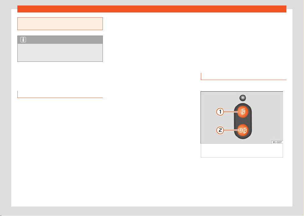
High-voltage battery
77
Charging settings in the infotainment system
●
Never touch the contacts of the charging
sock
et or the charging connector.
Note
The manual release mechanism of the
char
ging connector should only be used in
the event of a failure.
Charging settings in the in-
fotainment system
Battery Manager Menu
✓ Valid for: hybrid vehicles
The Battery Manager allows you to set or
select departure times for the programmed
charging of the high-voltage battery and for
the vehicle’s electric heating and air condition-
ing.
Open the Battery Manager menu
●
Switch the ignition on.
●
Switch on the infotainment system.
●
Select Batt
ery Manager from the main
menu.
It is possible to change the settings for immedi-
ate charging (the next charging process).
●
Reduce the charging current, e.g. when other
major consumers ar
e operating on a single line
of the electrical installation at the same time.
Charging power is reduced and charging time
is extended.
●
Set the desired temperature for the inde-
pendent air conditioning.
Departure time settings menu
Programmed charging (departure times) can
be set ›››page77.
●
Specify the amount of time for which you
w
ant the high-voltage battery to charge and
the air conditioning to be switched on inside the
vehicle.
Extended independent air conditioning
menu
●
Set the desired temperature for the inde-
pendent air conditioning.
The air conditioning works both when the vehi-
cle is connected to the grid and disconnected.
If you want to use the high-voltage battery as
the power supply, change the setting in the
Settings menu.
Charging settings menu
It is possible to configure the general settings
for the charging process.
●
Lower battery charge limit (minimum desired
char
ge level of the high voltage battery): a min-
imum range can be ensured with this function.
The vehicle charges directly once it has been
connected to a charging station or electrical
socket. The function is available if a departure
time has been activated ›››page77.
●
Air conditioning using the high-voltage bat-
tery: If the vehicle is not plugged in to an
external network and this option is enabled,
the electric range of the vehicle can be signif-
icantly reduced!
Departure time settings
✓ Valid for: hybrid vehicles
Fig.59 Behind the batt
ery charging socket
cover: charging buttons.
With programmed charging, the battery charge
can be pr
ogrammed and delayed so that the
desired battery level is reached at a certain
time when the vehicle is connected to the
charging socket.
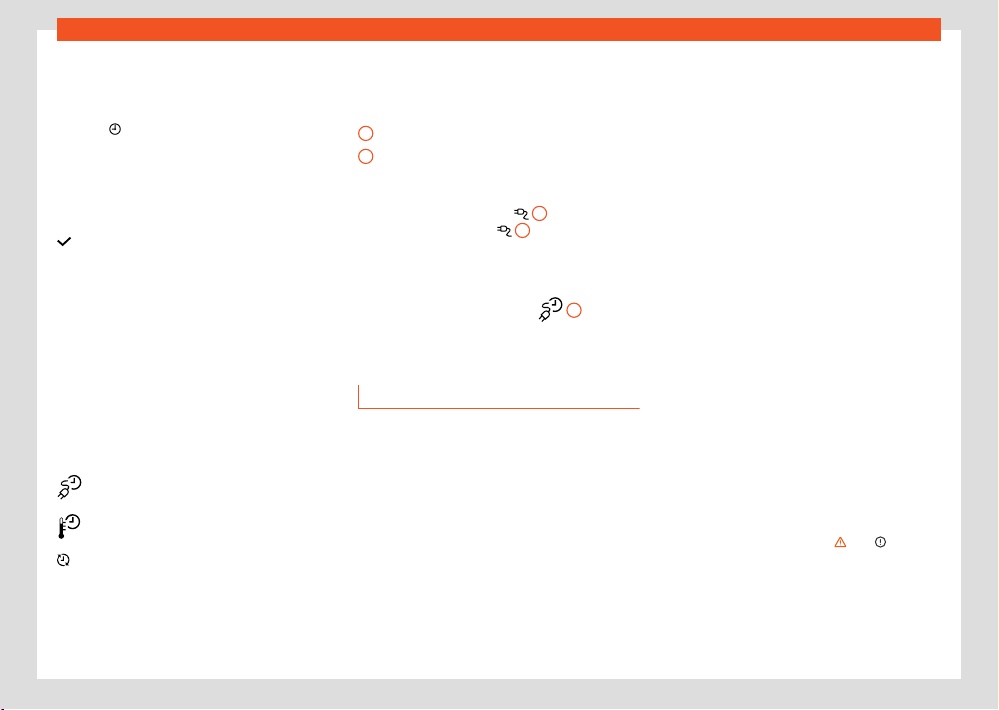
78
High-voltage battery
1
2
Viewing the departure times
●
Select Batt
ery Manager from the Infotain-
ment main menu.
●
Select
to open the overview of departure
times.
Depar
ture time settings
To set the desired departure time, touch the
corresponding function button or check the box
.
●
Departure time: T
ime, day of the week or set
a single or weekly departure time.
●
Air conditioning: the vehicle interior is heated
or cooled by the departure time.
●
Trough or night-time tari: a preferred pe-
riod of time for charging can be set.
Activating the departure time
Activate the departure time by checking the
box in the departure times overview.
Displays:
Charging activated at a departure time.
Air conditioning switched on at a depar-
ture time.
The departure time is used regularly.
Immediate charge buttons and scheduled
charge button
›››Fig.59
Immediate charge button
Scheduled charge button
When the high-voltage battery is charged im-
mediately, the immediate charge button lights
up on the charging socket
1
. Press the im-
mediat
e charge button
1
to interrupt the
char
ging process.
If a departure time has been programmed and
the charging cable is connected, the program-
med charging button lights up
2
.
Char
ging cable
Introduction
Valid for: hybrid vehicles
The type of charging cable supplied with the
vehicle depends on the delivery volume and
the specific technical specifications of each
country, e.g. charging connector connections
for power sockets.
SEAT recommends exclusively using the sup-
plied charging cable.
Notes on the charging cable
●
Handle with care.
●
Unroll and roll fully.
●
Do not twist or bend it over sharp edges.
●
Do not crush it or drive the vehicle over it.
●
Always unplug it by pulling on the connector.
●
Children should not use the charging cable.
●
Keep animals away from the charging cable.
●
After use, store it safely and without twisting it.
Notes on charging connectors and the
charging cable protection device
●
Do not touch the charging connector’s con-
tacts.
●
Protect from strong sunlight (outside temper-
atures no higher than 50°C or 122°F).
●
Do not drop them.
●
Protect from immersion in fluids such as rain
water.
●
Fit the protective caps after each use.
Cleaning the charging cable
Clean the surface of the charging cable with a
dry or slightly damp cloth ›››
, ››› .
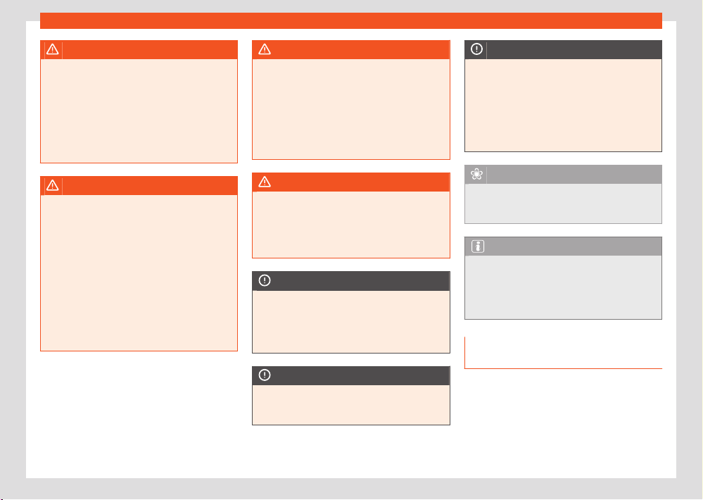
High-voltage battery
79
Charging cable
WARNING
Items that are not secured, or incorrectly se-
cur
ed can cause serious injury during sudden
manoeuvres or braking, or in the event of an
accident.
●
Store the charging cable securely in the
luggage compartment.
●
Use the organizer/protective cover provi-
ded with the cable for this purpose.
WARNING
Using a charging cable that has been dam-
aged or t
ampered with can cause serious in-
jury and fatal electric shocks.
●
Before each use check that the connectors
and the charging cable are undamaged, e.g.
check for cracks.
●
Never disassemble the charging cable or
its components.
●
Never use a charging cable that is dam-
aged or has been tampered with.
●
If the charging cable does not work prop-
erly, get a SEAT dealer to check it.
WARNING
The charging cable for electrical sockets
must al
ways be connected directly to an
electrical socket. Failure to do so could re-
sult in fire damage and damage to the charg-
ing cable or home electrical installation.
●
Never connect the charging cable to an
extension lead, cable reel, power strip or
adapter or timer.
WARNING
The high voltage system voltage is danger-
ous and can cause burns, other injuries and
f
atal electric shocks.
●
Only clean the charging cable when it is
unplugged.
NOTICE
Seek information regarding the appropriate
char
ging cable and the maximum permitted
charging current before travelling abroad. If
possible, use the charging cable supplied in
the country in question.
NOTICE
The charging cable, as portable electrical
equipment, may hav
e to be checked periodi-
cally. This requires a test adapter.
NOTICE
The charging cable can be damaged if not
cl
eaned properly.
●
Only water should be used for this pur-
pose, and never additional cleaning prod-
ucts.
●
Water should be prevented from getting
into the contacts.
For the sake of the environment
Charging cables must be disposed of in an
envir
onmentally friendly way and should not
be thrown in the household waste.
Note
The maximum charging capacity of the
saf
ety circuit that is used must be observed.
If the charging cable is planned into an elec-
trical socket on the same circuit as other
consumers, the circuit's fuses may trip.
Charging cable for alternating cur-
rent (AC) charging stations
Valid for: hybrid vehicles
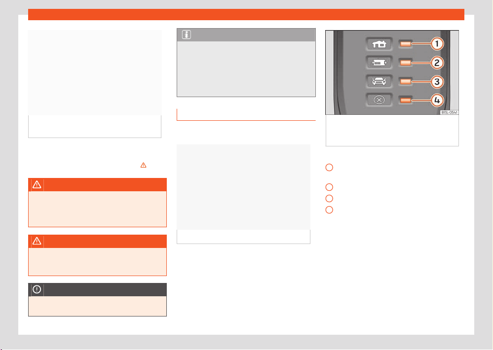
80
High-voltage battery
1
2
3
4
Fig.60 Char
ging cable for alternating current
(AC) charging stations.
The maximum charging current is 16 or 32
amps, depending on the v
ehicle’s features and
the charging cable that is supplied ›››
.
WARNING
Charging the high-voltage battery with an
inappr
opriate charging cable could cause
short circuits, serious injuries and fatal elec-
trical shocks.
WARNING
The charging cable should not be used as an
e
xtension lead. The charging process could
be aected.
NOTICE
Follow the manufacturer’s instructions and
indications when using the charging station.
Note
Charging with a charging cable for 16A is
not possibl
e at some charging stations that
support 32 A. This depends on the charging
station’s equipment.
●
Before charging the vehicle, find out about
the available charging technology.
Charging cable for power sockets
Valid for: hybrid vehicles
Fig.61 Char
ging cable for electrical sockets
Fig.62 On the char
ging cable for power
sockets: Indicator lamps on the protection
device.
›››Fig.62:
Indicator lamp of the connector and the
po
wer supply.
Control lamp of the protection device
Control lamp of the vehicle
Failure warning lamp
Charging cable information
Before using the charging cable, also follow the
instructions displayed on it and on the rear of
the protective device.
Protection device
The electronic protection device ›››Fig.62 en-
sures that the charging connector does not re-
ceive current until it is plugged in to the vehi-
cle's charging connector.

High-voltage battery
81
Charging cable
Self-check
When the char
ging cable is plugged into
the electrical socket, the protective device au-
tomatically performs a self-test. During this
check, all warning and indicator lamps turn on
briefly and go out one after the other. Upon
completion, the operational status at that time
is displayed.
Operating displays
One or more control lamps ›››Fig.62
1
,
2
o
3
light up green.
Display ›››Fig.62
Meaning
1
ignition The charging cable is
plugged int
o the mains
1
,
2
on,
3
flashes sl
owly
›››page81
The high-voltage battery
is charging.
1
2
and
3
on The charging process is
compl
ete. The high-volt-
age battery has charged.
Set the charging current
The charging cable limits the charging current
according to the available power supply.
If the local mains supply does not allow charg-
ing at the maximum charging current, the
charging current can be reduced, depending
on the charging setting features in the infotain-
ment system ›››page77.
Temperature control
The charging cable temperature control
switches on when the charging cable over-
heats, such as when it has been stored in a lug-
gage compartment exposed to high tempera-
tures or strong sunlight.
Display ›››Fig.62
Meaning
1
,
4
flashing The housing connector
has o
verheated.
2
,
4
flashing The protection device has
o
verheated.
If the charging process continues with a lower
current, both the operating indicator and the
warning lamp ›››Fig.62
4
flash r
ed.
●
Unplug the charging cable from the mains
and wait for it to cool down.
●
If it disconnects again, or the charging cur-
rent reduces and the cause does not seem to
be exposure to an external heat source, make
sure that the green control lamp is flashing
›››Fig.62. To check the charging cable, please
visit a SEAT dealer. Get an establishment that
specialises in electrical installations to check
the infrastructure connection.
Fault display
If the red warning light
4
flashes or t
urns on
without one of the indicator lamps ›››Fig.62
1
,
2
o
3
also turning on continuously on the
st
atus indicator, there is a fault.
Display ›››Fig.62
Meaning
1
flashing,
4
on or
flashing
Failure in the power sup-
ply.
2
flashing,
4
on or
flashing
Failure in the protection
de
vice.
3
flashing,
4
on or
flashing
Failure in the vehicle.
The charging process pauses or is cancelled.
●
Check the instructions located on the back of
the pr
otective devices.
●
Seek professional assistance if the fault per-
sists.
Note
If there is any other mains connection dur-
ing the char
ging process, or if the vehicle is
right next to the high voltage cables, charg-
ing from an electrical socket is not possible
in some cases. Additional mains connections:
●
Connecting a 12 volt battery charger.
●
Contact with a work tool connect to the
mains, such as a vehicle lift.
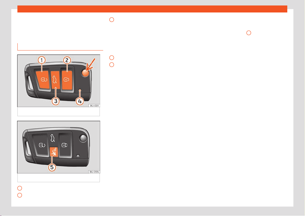
82
Opening and closing
1
2
3
4
5
Opening and closing
Set of v
ehicle keys
Vehicle key
Fig.63 V
ehicle key
Fig.64 V
ehicle key with alarm button.
Unlock the vehicle
L
ock the vehicle
Unlock only the rear lid.
Pr
ess the button until all the turn signals on
the vehicle flash briefly.
You have 2 minutes to open the rear lid.
Once this time has passed, it will lock
again. In addition, the lamp on the key
flashes.
Control lamp
Alarm button. Only press in the event of
an emergency! When the alarm button is
pressed, the vehicle's sounds and the turn
signals light up for a short time. Press again
to disconnect.
To fold and unfold the key blade, press the but-
ton ›››Fig.63 (arrow).
The vehicle can be locked and unlocked from a
distance using the vehicle key ›››page88.
The vehicle key includes an emitter and bat-
tery. The receiver is in the interior of the vehicle.
The range of the vehicle key with remote con-
trol and new battery is several metres around
the vehicle.
If it is not possible to open or close the vehicle
using the remote control key, this should be
re-synchronised ›››page84 or the battery
changed ›››page83.
Dierent keys belonging to the vehicle may be
used.
Control lamp on the vehicle key
When a button is pressed briefly on the vehi-
cle key, the control lamp
4
›››Fig.63 flashes
once briefly, but if pr
essed for a long period of
time, it will flash several times, for example, in
the convenience opening.
If the vehicle key control lamp does not light up
when the button is pressed, replace the key's
battery ›››page83.
Spare key
To obtain a spare key and other vehicle keys,
the vehicle chassis number is required.
Each new key contains a microchip which must
be coded with the data from the vehicle elec-
tronic immobiliser. A vehicle key will not work if
it does not contain a microchip or the microchip
has not been encoded. This is also true for keys
which are specially cut for the vehicle.
The vehicle keys or new spare keys can be
obtained from a SEAT Ocial Service, a spe-
cialised workshop or an approved key service
qualified to create this kind of key.
New keys or spare keys must be synchronised
before use ›››page84.
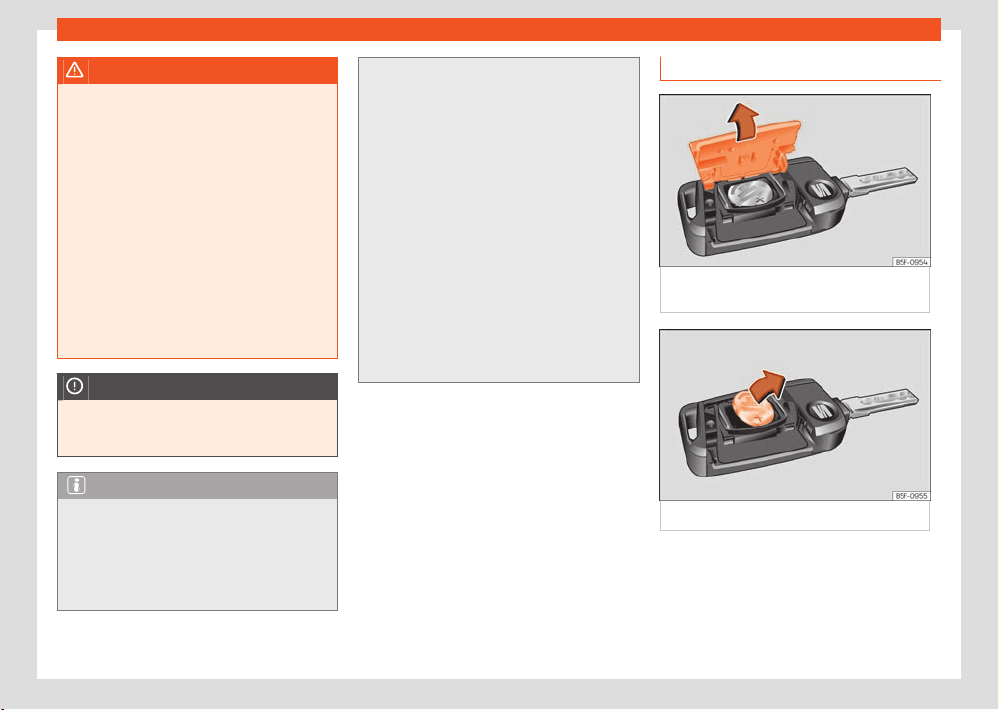
Opening and closing
83
Set of vehicle keys
WARNING
●
Never leave children or disabled persons in
the v
ehicle. In case of emergency, they may
not be able to leave the vehicle or manage
on their own.
●
An uncontrolled use of the key by third
parties could activate a piece of electrical
equipment (e.g. electric windows), with the
resulting accident hazard. The doors can be
locked using the remote control key. This
could become an obstacle for assistance in
an emergency situation.
●
Never forget the keys inside the vehicle. An
unauthorised use of your vehicle could result
in injury, damage or theft. Therefore always
take the key with you when you leave the
vehicle.
NOTICE
All of the vehicle keys contain electronic
components. Pr
otect them from damage, im-
pacts and humidity.
Note
●
Only use the key button when you require
the corresponding function. Pushing the but-
ton unnecessarily could accidentally unlock
the vehicle or trigger the alarm. It is also pos-
sible even when you are outside the radius of
action.
●
Key operation can be greatly influenced by
o
verlapping radio signals close to the vehicle
working in the same range of frequencies,
for example, radio transmitters or mobile tel-
ephones.
●
Obstacles between the remote control
and the v
ehicle, bad weather conditions and
discharged batteries can considerably re-
duce the range of the remote control.
●
If the buttons of the vehicle key are
pressed or one of the central locking but-
tons ›››page88 is pressed repeatedly in
short succession, the central locking briefly
disconnects as protection against overload-
ing. The vehicle is then unlocked. Lock it if
necessary.
●
Spare remote control keys are available at
your Technical Service, where they must be
matched to the locking system.
Changing the battery
Fig.65 V
ehicle key: opening the battery
compartment.
Fig.66 V
ehicle key: removing the battery.
SEAT recommends you ask a specialised work-
shop t
o replace the battery.
The battery is located to the rear of the vehicle
key, under a cover.
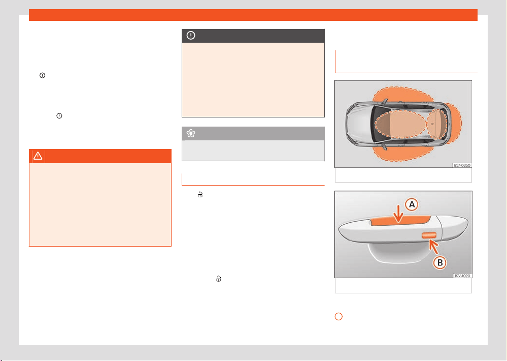
84
Opening and closing
A
Changing the battery
●
Unfold the vehicle key shaft.
●
Remove the cover from the back of the vehi-
cl
e key in the direction of the arrow ›››Fig.65 ,
›››
.
●
Remove the battery from the compartment
with a suit
able fine object ›››Fig.66.
●
Fit a new button battery into the compart-
ment ›››
.
●
Press the cover onto the key housing until it
clicks int
o place.
WARNING
Swallowing a battery with a 20 mm diameter
or any other butt
on battery can cause seri-
ous and even fatal injuries within a very short
time.
●
Keep the vehicle key and key fobs with bat-
teries out of reach of children.
●
If you suspect that someone may have
swallowed a battery, seek immediate medi-
cal attention.
NOTICE
●
If the battery is not changed correctly, the
v
ehicle key may be damaged.
●
Use of unsuitable batteries may damage
the vehicle key. For this reason, always re-
place the dead battery with another of the
same voltage, size and specifications.
●
When fitting the battery, check that the po-
larity is correct.
For the sake of the environment
Please dispose of your used batteries cor-
r
ectly and with respect for the environment.
Synchronize the vehicle key
If the
button is pressed frequently outside of
the v
ehicle range, it is possible that the vehicle
can no longer be locked or unlocked using the
key. In this case, the key must be resynchron-
ised as described below:
●
Unfold the vehicle key blade ›››page82 .
●
If necessary, remove the cover from the driver
door handle ›››page92.
●
Press the
button on the vehicle key. For this,
it must r
emain with the vehicle.
●
Open the vehicle within one minute using the
key blade. The key has been synchronised.
●
If necessary, fit the cap.
Keyless Access system
L
ocking and unlocking with the Key-
less Access system
Fig.67 K
eyless Access: proximity zones.
Fig.68 Driv
er door lever: sensor surfaces.
›››Fig.68
Unlocking sensor surface on the inside of
the door handl
e.
Opening and closing
85
Keyless Access system
B
Locking sensor surface on the outside of
the door handl
e.
Depending on the equipment, the vehicle may
have the Keyless Access system. This is a key-
less locking and starting system that can un-
lock and lock the vehicle without actively using
its key. For this, it is only necessary that there
is a valid vehicle key in the detection area cor-
responding to the attempted access to the ve-
hicle.
Configuring the Keyless Access system
The behaviour of the Keyless Access system
can be adjusted in the Vehicle settings menu
of the Infotainment system ›››page37.
If the Keyless Access function is disabled, its
operation is limited.
Unlock the vehicle
●
Touch the sensor surface on the inside of the
handle
A
. All turn signals flash twice.
If sel
ective opening is fitted, touching the sen-
sor's surface twice unlocks the entire vehicle.
If the vehicle is not unlocked for an extended
period, the function is deactivated. The function
will reactivate the next time that the vehicle is
unlocked with the remote control.
Lock the vehicle
●
Park the vehicle.
●
Touch the sensor surface ›››Fig.68
B
on the
outside of the door handl
e. All turn signals flash
once.
To check that the vehicle is properly locked,
the unlocking function is deactivated for a few
seconds.
Unlocking the rear lid
When the vehicle is locked, the rear lid auto-
matically unlocks when it is opened if there is
a vehicle key in its proximity zone. The rear lid
locks again after closing.
Temporarily deactivating the Keyless Ac-
cess system
The “Keyless Access” system’s unlocking func-
tion can be temporarily deactivated:
●
Move the gear lever to position P since other-
wise the vehicle cannot be locked.
●
Lock the vehicle using the
button on the
v
ehicle key.
●
Within 5 seconds, touch the sensor on the
outside of the door handle ›››Fig.68
B
once.
Do not grip the handl
e while doing so. This tem-
porarily deactivates the Keyless Access system.
●
Check that it is deactivated by pulling the
door handle after at least 10 seconds. It should
not be possible to open the door.
The next time, the vehicle can only be unlocked
electronically with the vehicle key. After being
unlocked the next time, the Keyless Access sys-
tem will be activated again ›››
.
P
ermanently disabling the Keyless Access
system
The Keyless Access system can also be perma-
nently deactivated in the infotainment system
›››
.
Conv
enience functions
To close all the electric windows and the sun-
roof using the comfort function, keep a finger
for a few seconds on the locking sensor surface
›››Fig.68
B
of the door handle until the win-
do
ws and roof have closed.
How the doors open when touching the sensor
surface on the door handle will depend on the
settings that have been activated in the info-
tainment system, using the function button
> Settings > Opening and closing.
NOTICE
Deactivating the Keyless Access system also
deactiv
ates the sensor controlled opening
and closing of the rear lid, although the func-
tion is shown as “active” in the vehicle menu.

86
Opening and closing
Troubleshooting
The K
eyless Access system does not work
The operation of the sensor surfaces may be
limited if they are very dirty.
●
Clean the sensor surfaces.
All turn signals flash four times
The key that was last used is still inside the vehi-
cle.
●
Remove the key and lock the vehicle.
Automatic deactivation of the sensor surfa-
ces
The sensor surfaces are deactivated in the fol-
lowing cases:
●
If the vehicle is not unlocked or locked for a
long period of time.
●
If any of the sensor surfaces are activated
unusually often.
To reactivate the sensor surfaces:
●
Unlock the vehicle using the
button on the
v
ehicle key.
NOTICE
The sensor surfaces on the door handles
may activ
ate if hit by a jet of water or high
pressure steam if there is a valid vehicle key
in the proximity area. If at least one of the
windows is open and the sensor surfaces on
one of the handles permanently activates,
all of the windows will close. If the jet of wa-
ter or steam is briefly moved away from the
sensor surfaces of one of the handles and
redirected towards them, all of the windows
may open.
Note
If the message Keyless system faulty
is displ
ayed on the instrument cluster dis-
play, abnormalities may occur in the opera-
tion of the Keyless Access system. Contact a
specialised workshop.
Note
If there is no vehicle key inside the vehicle or
the syst
em fails to detect one, a warning will
display on the instrument cluster screen. This
could happen if any other radio frequency
signal interferes with the key signal or if the
key is covered by another object, e.g. a metal
case.
Central locking
Intr
oduction
Central locking functions correctly when all the
doors and the rear lid are correctly shut. If
the driver door is open, the vehicle cannot be
locked with the key.
WARNING
The incorrect use of the central locking sys-
tem may cause serious injuries.
●
The central locking system will lock all
doors. A vehicle locked from the inside can
prevent any non-authorised individual from
opening the doors and accessing the vehicle.
Nevertheless, in case of emergency or acci-
dent, locked doors will complicate access to
the vehicle interior to help the passengers.
●
Never leave children or disabled people
alone in the vehicle. The central locking but-
ton can be used to lock all the doors from
within. Therefore, passengers will be locked
inside the vehicle. Individuals locked in the
vehicle can be exposed to very high or very
low temperatures.
●
Depending on the time of the year, temper-
atures inside a locked and closed vehicle can
be extremely high or extremely low resulting
in serious injuries and illness or even death,
particularly for young children.

Opening and closing
87
Central locking
●
Never leave individuals locked in a closed
and l
ocked vehicle. In case of emergency,
they may not be able to exit the vehicle by
themselves or get help.
Description
Central locking allows all doors, the rear lid and
the tank flap to be unlocked centrally:
Hybrid vehicles: the fuel tank flap does not un-
lock with the central locking ›››page309.
●
From outside, using the vehicle key
›››page88.
●
From outside with the Keyless Access system
›››page84.
●
From inside, by pushing the central locking
button ›››page88.
Self-locking system to prevent involuntary
unlocking
It is an anti-theft system and prevents the unin-
tentional unlocking of the vehicle. If the vehicle
is unlocked and none of the doors (including
the boot) are opened within 45 seconds, it re-
locks automatically.
Automatic locking (Auto Lock)
The vehicle locks automatically at over a speed
of approx. 15 km/h (9 mph). The fuel tank flap is
unlocked so that you can refuel without getting
out of the vehicle.
Hybrid vehicles: the fuel tank flap remains
locked ›››page309.
When the vehicle is locked, the control lamp
of the central locking button lights up yellow.
Aut
omatic unlocking (Auto Unlock)
If one of the following conditions is met, all
doors and the rear lid are unlocked automati-
cally:
●
The electronic parking brake is engaged and
the ignition is switched o.
●
EITHER: the inside door handle is pulled. This
applies when driving at under 15 km/h (9 mph).
●
OR: in the event of an accident and an airbag
has been triggered ›››page90.
Automatic unlocking allows third parties to ac-
cess the interior of the vehicle to provide assis-
tance if necessary.
Turn signals
The turn signals will flash twice when the vehi-
cle is unlocked and once when the vehicle is
locked.
If it does not flash, this indicates that one of the
doors, the rear lid or the bonnet is not closed
correctly.
Accidental lock-out
The central locking system prevents you from
being locked out of the vehicle in the following
situations:
●
If the driver door is open, the vehicle can-
not be locked with the central locking switch
›››page88.
Lock the vehicle with the remote control key,
when all the doors and the rear lid have been
closed. This prevents the accidental locking of
the vehicle.
Central locking settings
Central locking settings can be changed in the
Infotainment system.
Selective unlocking of the doors
●
Press the function button
> Settings >
Opening and closing > Central lock-
ing > Door unlocking.
Y
ou can choose to unlock all the doors or only
the driver door when you unlock the vehicle.
In all the options, the fuel tank flap is also un-
locked.
With the Driver setting, when you press the
button on the remote control key once, only the
driv
er door is unlocked. If that button is pressed
twice, the rest of the doors and the rear lid will
be unlocked.
If the
button is pressed, all the vehicle doors
ar
e locked. At the same time, a confirmation
signal is heard.
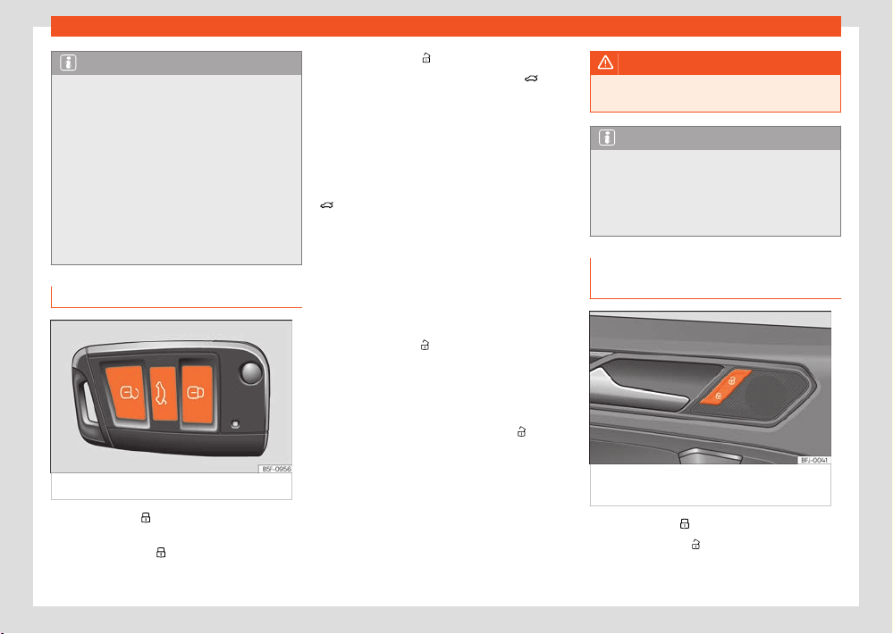
88
Opening and closing
Note
●
Never leave any valuable items in the vehi-
cl
e unattended. Even a locked vehicle is not
a safe.
●
If the LED on the driver door sill lights
up for about 30 seconds when the vehi-
cle is locked, the central locking system or
anti-theft alarm is not working properly. You
should have the fault repaired at a SEAT O-
cial Service or specialised workshop.
●
Vehicle interior monitoring by the anti-theft
alarm system will only function as intended if
the windows and sunroof are closed.
Unlock and lock with the key
Fig.69 R
emote control key: keys.
●
Lock: press the
›››Fig.69 butt
on.
●
Locking the vehicle without the “Safe” secur-
ity system: push the
button again and hold for
2 seconds.
●
Unlock: press the
button.
●
Unlocking the rear lid: hold down the but-
t
on for at least 1 second.
The vehicle will be locked again automatically
if you do not open one of the doors or the rear
lid within 45 seconds after unlocking the car.
This function prevents the vehicle from remain-
ing unlocked if the unlocking button is pressed
by mistake. This does not apply if you press the
button for at least one second.
Sel
ective unlocking system
The selective unlocking system allows you to
only unlock the driver door and the fuel tank
flap. All other doors and the rear lid remain
locked.
Unlocking the driver's door and tank flap:
●
Press (once) the
button on the remote con-
tr
ol key or turn the key once in the opening
direction.
Unlocking all the doors, the rear lid and the tank
flap simultaneously:
●
Within 5 seconds, press (twice) the
button
on the r
emote control key, or turn the key twice
within 5 seconds in the opening direction.
The “Safe” security system and the anti-theft
alarm deactivate immediately when only the
driver door is opened.
In vehicles with Infotainment system, you can
programme the security central locking system
directly ›››page87.
WARNING
Observe the safety warnings ›››page89,
Saf
e security system.
Note
●
Do not use the remote control key until the
v
ehicle is visible.
●
Other functions of the remote control key
›››page98, Opening and closing the win-
dows.
Unlocking and locking from the in-
side
Fig.70 On the driv
er's door: central locking
button.
●
Lock: press the
›››Fig.70 butt
on.
●
Unlock: press the
›››Fig.70 butt
on.
Opening and closing
89
Central locking
Please note the following when using the cen-
tr
al locking switch to lock your vehicle:
●
It is not possible to open the doors or the
rear lid from the outside (for safety reasons, e.g.
when stopped at trac lights).
●
The LED in the central locking switch lights up
when all the doors are closed and locked.
●
You can open the doors individually from the
inside by pulling the inside door handle.
●
The fuel tank flap remains unlocked.
Hybrid vehicles: the fuel cap remains locked
›››page309.
●
In the event of an accident in which the air-
bags inflate, doors locked from the inside will
be automatically unlocked to facilitate access
and assistance.
WARNING
●
The central locking switch also works with
the ignition s
witched o, except when the
“Safe” security system is activated.
●
The central locking switch does not oper-
ate if the vehicle is locked from the outside
and the security system is switched on.
●
Locked doors could delay assistance in an
emergency. Do not leave anyone, especially
children, in the vehicle.
Note
Your vehicle will lock automatically when it
r
eaches a speed of about 15 km/h (9 mph)
(Auto Lock) ›››page87. You can unlock the
vehicle again using the
button on the cen-
tr
al locking switch.
“Safe” security system
Depending on its equipment, the vehicle may
be fitted with the “Safe” security system.
When the vehicle is locked, the “Safe” security
system puts the door handles out of operation
and hinders possible attempts by people to ac-
cess the vehicle. The doors cannot be opened
from inside ›››
.
Disabling the “Saf
e” security system
The “Safe” security system may be disabled in
any of the following ways:
●
Press the vehicle key button
again within 2
seconds.
●
Touch the sensor surface on the outside
of the door handl
e again within 2 seconds
›››page84.
●
Switch the ignition on.
●
OR: deactivate interior monitoring and the
anti-tow system ›››page91.
Depending on the equipment, before locking
the v
ehicle temporarily deactivate interior mon-
itoring and the anti-tow system in the Vehicle
settings menu of the infotainment system
›››page91.
The instrument cluster may display an indica-
tion that the “Safe” security system is switched
on.
When the “Safe” security system is deactivated,
the following needs to be taken into account:
●
The vehicle can be opened and unlocked
fr
om the inside using an inside door handle.
●
The anti-theft alarm is active ›››page90.
●
The interior monitoring system and the anti-
tow system are disabled ›››page91.
“Safe” status
The flashing frequency of the diode in the door
sill immediately confirms the process. Initially,
the diode flashes in a fast sequence for a brief
period, then it stops for approximately 30 sec-
onds and, lastly continues flashing slowly.
WARNING
Using the “Safe” security system negligently
or without paying due att
ention can cause
serious injuries.
●
Never leave anyone inside the vehicle
when you lock it with the key. When the
“Safe” security system is active the doors
cannot be opened from the inside!
90
Opening and closing
Troubleshooting
The contr
ol lamp remains on
The red LED on the driver’s door flashes at short
intervals and then stays on. There is a fault in
the locking system.
●
Contact a specialised workshop. SEAT rec-
ommends visiting a SEAT dealership for this.
The turn signals do not flash
If the turn signals do not flash as a confirmation
when the vehicle is locked:
●
At least one door or the rear lid are not closed
or
●
The engine bonnet is not closed.
The vehicle locks automatically
If one of the following conditions is met, the
vehicle re-locks automatically after approx. 45
seconds.
●
The vehicle has been unlocked, but has not
been opened.
●
The ignition has not been switched on.
●
The rear lid has not been opened.
●
The vehicle has been unlocked with the lock-
ing cylinder.
●
The vehicle has been locked with the button
l
ocated in the vehicle interior.
What happens when locking the vehicle with
a second k
ey
They key inside the vehicle is blocked and can-
not be used to start the engine as soon as the
vehicle is locked from the outside with a second
key. To activate the key inside the vehicle to al-
low it to switch on the engine, press its
button.
L
ocking the vehicle after an airbag is trig-
gered
When an airbag is triggered as a result of an
accident, the vehicle is fully unlocked. Depend-
ing on the extent of the damage, the vehicle
may be relocked after the accident as descri-
bed below:
●
Switch the ignition o.
●
Open the driver's door and close it again.
●
Lock the vehicle.
Note
If the 12-volt vehicle battery has little or no
char
ge, or the vehicle key battery is almost
or entirely out of charge, you will probably
not be able to lock or unlock the vehicle
with the Keyless Access system. The vehi-
cle can be unlocked and locked manually
›››page92.
Note
If there is no vehicle key in the vehicle or
the syst
em does not detect it, a warning will
be displayed on the instrument cluster. This
could happen if any other radio frequency
signal interferes with the key signal or if the
key is covered by another object, e.g. a metal
case.
Anti-theft alarm
Description
Depending on the equipment, the vehicle may
be fitted with an anti-theft alarm.
The theft alarm monitors the doors, bonnet and
rear lid.
The anti-theft alarm system activates automat-
ically when the vehicle is locked.
If the vehicle is not opened electronically with
a valid key, the alarm triggers and emits audio
and light signals for a maximum of approx. 5
minutes.
When is the anti-theft alarm triggered?
●
If a mechanically unlocked door is opened
with the v
ehicle key, you have 15 seconds to
switch on the ignition before the alarm is trig-
gered (depending on markets, the 15 seconds
waiting time disappears and the alarm is trig-
gered immediately when the door is opened).
Opening and closing
91
Anti-theft alarm
●
If the bonnet is opened.
●
If the rear lid is opened.
●
If an invalid vehicle key is used.
●
If there are movements inside the vehicle (in
v
ehicles with interior monitoring ›››page91).
●
If the vehicle is lifted or towed (for vehicles
with an anti-tow system ›››page91.
●
If the vehicle is transported on a ferry or by
rail (in vehicles with an anti-tow system or inte-
rior monitoring ›››page91).
●
If the 12-volt battery is disconnected.
●
If the window is broken.
●
When a trailer connected to the theft alarm
system is unhitched.
Switching o the alarm
●
Unlock the vehicle with the vehicle key un-
locking button
.
●
Grip the door handle.
●
Switch the ignition on.
Note
●
After 28 days, the indicator light will be
s
witched o to prevent the battery from ex-
hausting if the vehicle has been left parked
for a long period of time. The alarm system
remains activated.
●
If, after the audible warning goes o, an-
other monit
ored area is accessed (e.g. the
rear lid is opened after a door has been
opened), the alarm is triggered again.
●
The anti-theft alarm is not activated when
the v
ehicle is locked from within using the
central locking button
.
●
If the driver door is unlocked mechanically
with the k
ey, only the driver door is unlocked,
the rest of the doors remain locked. Only
when the ignition has been turned on will the
other doors be available - but not unlocked -
and the central locking button will be activa-
ted.
●
Vehicle monitoring remains active even if
the battery is disconnected or not working
for any reason.
Interior monitoring and anti-tow sys-
tem
If movement is detected in the vehicle interior
while the vehicle is locked, the interior monitor-
ing triggers the alarm.
If it detects that the vehicle is being lifted, the
anti-tow system triggers the alarm.
Switching on the interior monitoring and the
anti-tow systems
●
Lock the vehicle. When the anti-theft alarm is
activ
ated, the interior monitoring and the anti-
tow system are as well.
Depending on the equipment, the use of a par-
tition net can aect the oper
ation of the interior
monitoring system.
Temporarily switching o the interior moni-
toring and anti-tow systems
●
Open the vehicle with the key, either me-
chanically or by pressing the
button on the
r
emote control. The time period from when the
door is opened until the ignition is turned on
should not exceed 15 seconds, otherwise the
alarm will be triggered.
●
Press the
button on the remote control
twice
. The interior monitoring and the anti-tow
systems will be deactivated. The alarm system
remains activated.
Disconnect through the infotainment system
●
Press the function button
> Settings >
Opening and closing > Central lock-
ing > Interior monitoring.
The int
erior monitoring and anti-tow system re-
main deactivated until the next time the vehicle
is locked.
To avoid false alarms, deactivate interior moni-
toring and the anti-tow system in the following
situations:
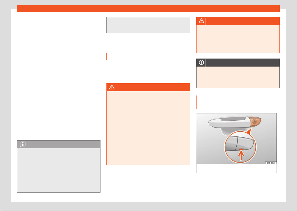
92
Opening and closing
●
When people or animals remain inside the ve-
hicl
e.
●
When the vehicle is to be loaded onto an-
other means of transport, transported or towed.
●
When the vehicle is to be left in a car wash or
is to be parked in a double-decker garage.
Risk of false interior monitoring alarms
The interior monitoring system will only operate
correctly if the vehicle is completely locked.
Please bear in mind all legal provisions. The
following situations may cause a false alarm:
●
If one or more windows are partially or com-
pletely open.
●
If the sliding/tilting roof is partially or fully
open.
●
If light objects are left inside the vehicle, e.g.
loose paper or items hanging from the interior
mirror.
●
If the vibrate function of a mobile left inside
the vehicle is activated.
Note
●
It is not possible to permanently deactivate
the int
erior monitoring and anti-tow systems.
●
If any doors or the rear lid are open when
the anti-theft alarm is activated, only the
alarm will be activated. The interior monitor-
ing and anti-tow systems will only activate
once all of the doors and the rear lid are
closed.
●
When the interior monitoring and anti-tow
syst
ems are switched o, the “Safe” security
system is also switched o ›››page89.
Doors
Introduction
The doors and rear lid can be locked manually
and partially opened, for example if the key or
the central locking is damaged.
WARNING
Opening and closing doors carelessly can
cause serious injury.
●
If the vehicle is locked from outside, the
doors and windows cannot be opened from
the inside.
●
Never leave children or disabled people
alone in the car. They could be trapped in the
car in an emergency and will not be able to
get themselves to safety.
●
Depending on the time of the year, temper-
atures inside a locked and closed vehicle can
be extremely high or extremely low resulting
in serious injuries and illness or even death,
particularly for young children.
WARNING
Getting in the way of the doors and the rear
lid is danger
ous and can lead to serious in-
jury.
●
Open and close the doors and the rear lid
only when there is nobody in the way.
NOTICE
When opening and closing in an emergency,
car
efully disassemble components and then
reassemble them carefully to avoid damage
to the vehicle.
Emergency unlocking or locking of
the driver’s door
Fig.71 Driv
er door lever: hidden lock cylinder.
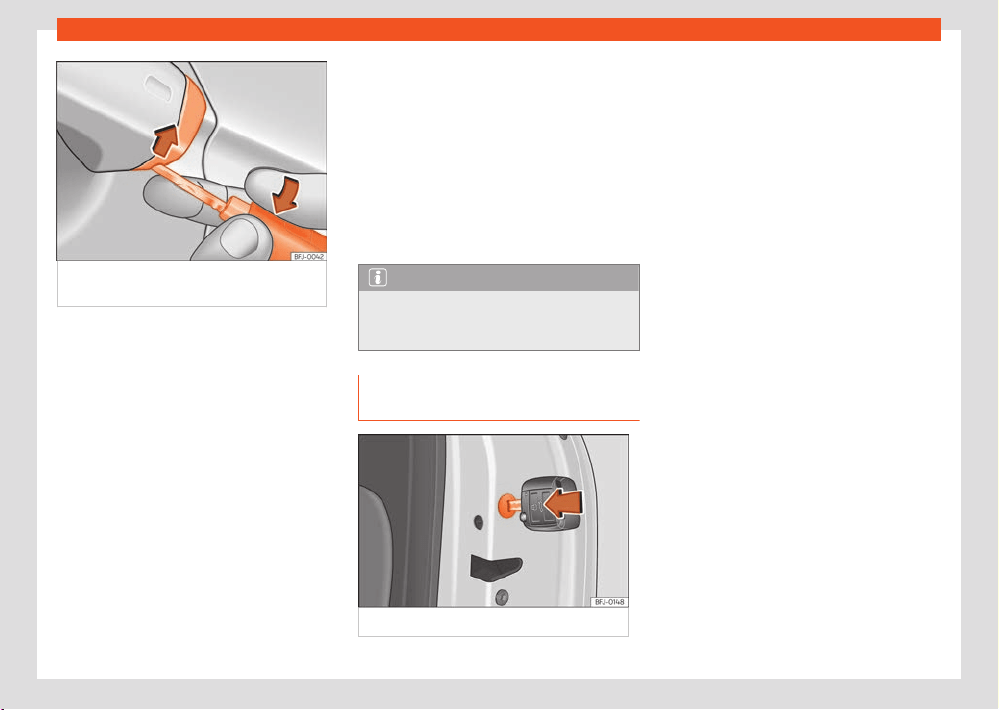
Opening and closing
93
Doors
Fig.72 Driv
er's door handle: pry the cover
open.
If the central locking system should fail to op-
er
ate, the driver door can still be locked and
unlocked by turning the key in the lock.
As a general rule, when the driver door is locked
manually all other doors are locked. When it is
unlocked manually, only the driver door opens.
Please observe the instructions relating to the
anti-theft alarm system ›››page90.
●
Unfold the vehicle key shaft.
●
Insert the key shaft into the lower opening
in the cover on the driver door handle then re-
move the cover upwards ›››Fig.72.
●
Insert the key blade into the lock cylinder to
unlock or lock the vehicle.
Special characteristics
●
The anti-theft alarm will remain active when
vehicles are unlocked. However, the alarm will
not be triggered ›››page90.
●
After the driver door is opened, you have 15
seconds to switch on the ignition. Once this
time has elapsed, the alarm is triggered.
●
Switch the ignition on. The electronic immo-
bilizer recognises a valid vehicle key and deac-
tivates the anti-theft alarm system.
Note
The anti-theft alarm is not activated when
the v
ehicle is locked manually using the key
shaft ›››page86.
Emergency lock of doors without lock
cylinders
Fig.73 L
ocking the door manually.
If the central locking system should fail to work
at any time
, doors with no lock cylinder will
have to be locked separately.
The emergency lock is located on the front of
the front passenger's door and the rear doors. It
can only be seen if the door is open.
●
Insert the key in the slot ›››Fig.73 (arrow) and
turn it to the right as far as it will go (if the door
is on the right side) or to the left (if the door is on
the left side).
Once the door has been closed it can no longer
be opened from the outside. Pull the interior
door handle once to unlock and open the door.
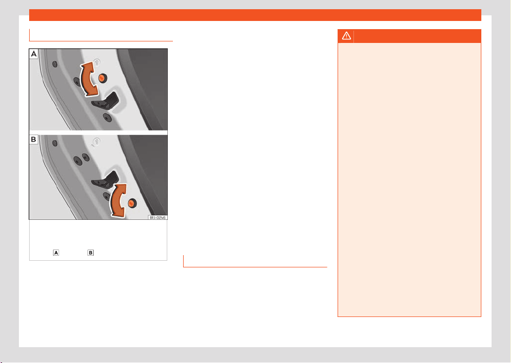
94
Opening and closing
Child lock
Fig.74 Chil
d safety lock on the left door
(symmetrical on the right door). Depending on
the version or country, the vehicle is fitted with
variant
or variant .
The childproof lock prevents the rear doors
fr
om being opened from the inside. This system
prevents minors from opening a door acciden-
tally while the vehicle is running.
This function is independent of the vehicle elec-
tr
onic opening and locking systems. It only af-
fects rear doors. It can only be activated and
deactivated manually, as described below.
Activating the childproof lock
●
Unlock the vehicle and open the door in
which you wish to activate the childproof lock.
●
With the door open, turn the slot with the vehi-
cle key clockwise for the left doors ›››Fig.74
and anticlockwise for the right doors.
Once the childproof lock is activated, the door
can only be opened from the outside.
Deactivating the childproof lock
●
Unlock the vehicle and open the door whose
childproof lock you want to deactivate.
●
With the door open, turn the slot with the
vehicle key anticlockwise for the left doors
›››Fig.74 and clockwise for the right doors.
Rear lid
Introduction
The rear lid unlocks and locks together with the
doors.
On vehicles with the Keyless Access start/lock-
ing system, the rear lid automatically unlocks
when it is opened ›››page84.
WARNING
Careless and unsuitable locking, opening
and cl
osing of the rear lid can cause acci-
dents and serious injury.
●
Do not close the rear lid by pushing it down
with your hand on the rear window. The glass
could smash. Risk of injury!
●
Ensure the rear lid is locked after closing
it. If not, it may open unexpectedly while driv-
ing.
●
Closing the rear lid without observing and
ensuring it is clear could cause serious injury
to you and to third parties. Make sure that no
one is in the path of the rear lid.
●
Never drive with the rear lid open or half-
closed, exhaust gases may penetrate into
the interior of the vehicle. Danger of poison-
ing!
●
Never open the rear lid if there is cargo,
e.g. bicycles, attached to it. The rear lid may
close by itself due to the additional weight. If
necessary, remove the cargo first or hold the
rear lid.
●
Never leave the vehicle unattended or al-
low children to play inside or next to it, espe-
cially if the rear lid is open. Children could
enter the luggage compartment, close the
rear lid and become trapped. A locked vehi-
cle can reach extremely high and low tem-
peratures, depending on the time of year,
thus causing serious injuries, illness or even
death.
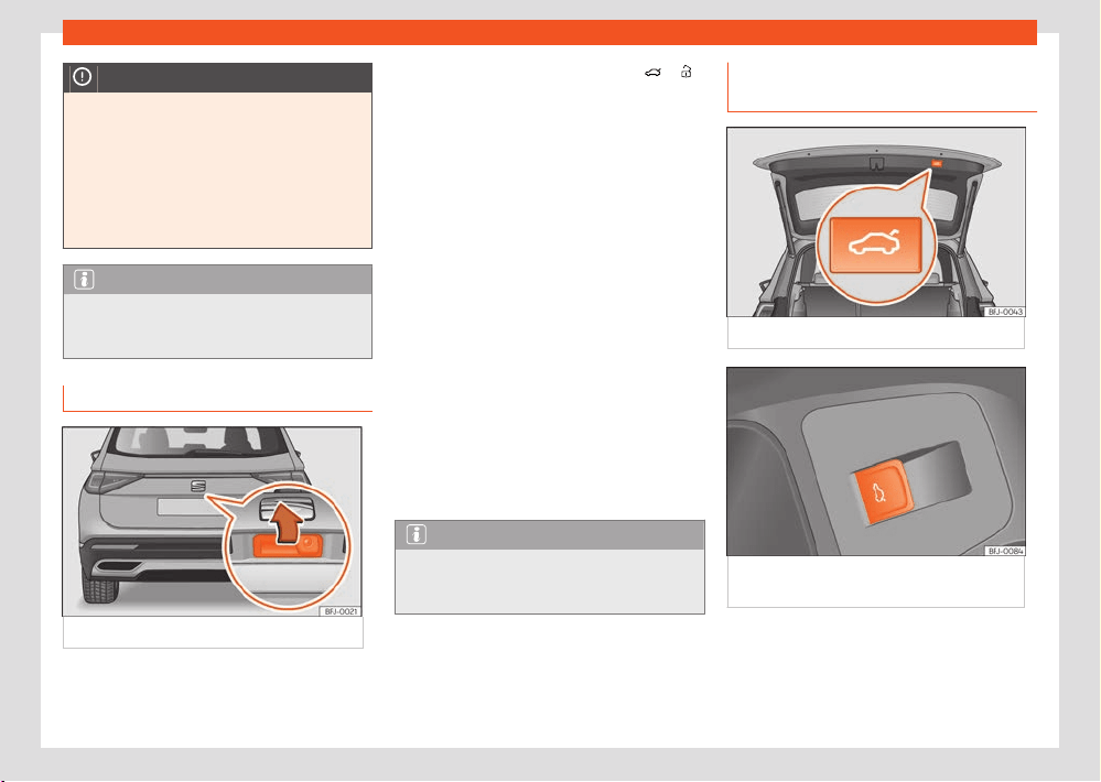
Opening and closing
95
Rear lid
NOTICE
●
Before opening or closing the rear lid, make
sur
e that there is enough space to open or
close it, e.g. when pulling a trailer or in a ga-
rage.
●
Never use the rear wiper or rear spoiler to
secure cargo or as a handhold. This could
cause damage that could lead to the break-
age of the rear wiper or spoiler.
Note
Before closing the rear lid, make sure that
the k
ey has not been left inside the luggage
compartment.
Opening and closing the rear lid
Fig.75 R
ear lid: opening from the outside.
The rear lid opening system operates electri-
cally.
To lock or unlock the rear lid, press the
or
buttons of the vehicle key.
Opening and cl
osing
●
Open: place slight pressure on the handle.
The rear lid opens automatically. ›››Fig.75.
●
Close: grip the rear lid by one of the handles
on the interior trim and move it downwards to
close.
OR: press the button on the rear lid ›››Fig.76.
If the doors are locked, the rear lid is also
locked.
A warning appears on the instrument panel
display if the rear lid is open or not properly
closed.
The rear lid locks automatically while driving.
When the outside temperature is around freez-
ing point, the opening mechanism cannot al-
ways automatically raise the partially opened
rear lid. Lift the rear lid by hand.
Note
If the rear lid is not opened within a few mi-
nut
es of being unlocked, it re-locks automati-
cally.
Rear lid with electric opening and
cl
osing
Fig.76 R
ear lid: button to close rear lid.
Fig.77 Driv
er door: button to open and close
rear lid.

96
Opening and closing
Opening the rear lid
●
Unlock the vehicle and briefly pr
ess the han-
dle of the rear lid. On vehicles with Keyless Ac-
cess you can directly press the handle of the
rear lid. The rear lid is unlocked if an authorised
key is recognised in the proximity of the vehicle.
●
OR: pull the
button on the driver door up-
w
ards ›››Fig.77. The button also works when
the ignition is switched o.
●
OR: press and hold the
button of the ve-
hicl
e key for approx. 1 second. If the vehicle is
locked, only the rear lid is unlocked (the doors
remain locked).
●
OR: on vehicles with Keyless Access and sen-
sor-controlled opening you can open the rear
lid by moving one foot in the area of the sensors
located below the rear bumper (Easy Open
›››page97). The rear lid will open automati-
cally.
Closing the rear lid
●
Briefly press the
button on the rear lid
›››Fig.76, ››› in Intr
oduction on page94.
●
EITHER: pull the
button on the driver door
up
wards ›››Fig.77.
●
OR: on v
ehicles with Keyless Access, press
and hold the
vehicle key button until the rear
lid is cl
osed or move one foot in the area of the
sensors located below the rear bumper (Easy
Open ›››page97). The vehicle key must be
in the Keyless Access system detection zone at
the rear outside the vehicle.
●
OR: manually mo
ve the rear lid in the direc-
tion of closing until it closes automatically.
●
The rear lid goes down automatically to the
final position and also closes automatically
›››
in Intr
oduction on page94.
Interrupting opening or closing
After beginning to open or close the rear lid,
the action can be halted by pressing one of the
buttons
.
If you pr
ess one of the
buttons again, the
r
ear lid will move again in the original direction.
If the rear lid meets with resistance or an ob-
stacle during the automatic opening or closing,
opening or closing will be interrupted immedi-
ately. For the closing process, the rear lid opens
again slightly.
●
Check why it has not been possible to open
or close the rear lid.
●
Try to open or close the rear lid again.
●
If necessary, the rear lid can be opened or
closed by hand using reasonable force.
Restrictions if the vehicle has a third row of
seats
If the vehicle is fitted with a third row of seats,
it will not be possible to close the tailgate with
the
button, on the driver’s door ›››Fig.7
7, or
with the vehicle key. This happens regardless of
whether the seats in the third row are folded or
not.
Particular features if towing a trailer
If the factory-fitted towing bracket is electri-
cally connected to a trailer ›››page297, the
electric rear lid can only be opened or closed
with the buttons on the rear lid itself or by using
the Easy Open function.
Audible warnings
Throughout the process of opening or closing
the rear lid, acoustic warnings can be heard.
Exception: when the rear lid is opened manually
using the handle or the Easy Open function with
the movement of the foot or closed using the
button on the rear lid itself ›››Fig.76.
Modifying and memorising the opening an-
gle
If the space behind or above the vehicle is less
than the travel area of the rear lid, you can
change the opening angle of the rear lid.
To memorise a new opening angle, the rear lid
must be open at least halfway.
●
Interrupt the opening process in the desired
position.
●
Press the
›››Fig.76 butt
on on the rear lid
for at least 3 seconds.
The opening angle is memorised. Memorisation
is indicated by blinking of the hazard warning
lights and an audible warning.
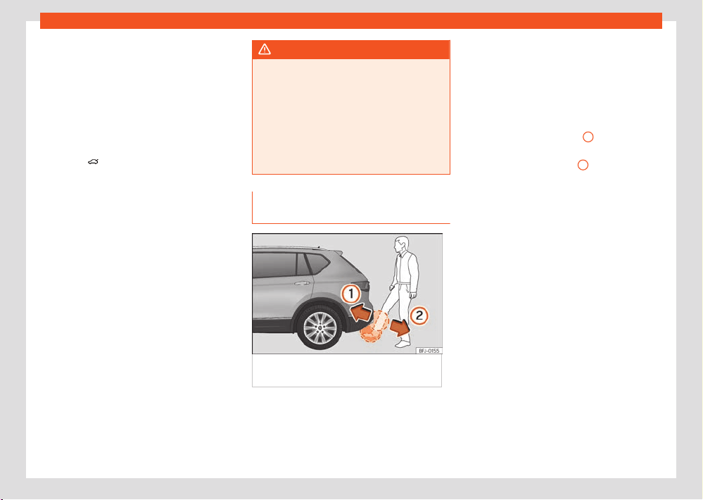
Opening and closing
97
Rear lid
Resetting and memorising the opening an-
gl
e
For the rear lid to reopen completely, the open-
ing angle must be reset and memorised again.
●
Release the rear lid and open it to the memo-
rised height.
●
Lift the rear lid by hand as far as it goes. To do
this, some force will have to be used.
●
Press the
›››Fig.76 butt
on on the rear lid
for at least 3 seconds.
●
This resets and memorises the factory-set
opening angle. Memorisation is indicated by
blinking of the hazard warning lights and an
audible warning.
Automatic protection against overheating
If the system is operated repeatedly in a short
space of time, it automatically switches o to
prevent overheating.
Once the system is cool again, the function can
be reused. Until then, the rear lid can only be
opened and closed by hand using reasonable
force.
If with the rear lid open the vehicle battery is
disconnected ›››page343 or the correspond-
ing fuse burns out ›››page326, the system will
have to be reset. This requires closing the rear
lid completely once.
Emergency unlocking
›››page98.
WARNING
If a lot of snow builds up on the rear lid or it
is heavily l
oaded, the rear lid may not open
or, after opening, it may lower by itself due to
the extra weight and cause serious injury.
●
Do not open the rear lid when there is a lot
of snow on it or when carrying a load (e.g. on
a rack).
●
Before opening the rear lid, remove the
snow or the load.
Rear lid with sensor-controlled
opening and closing (Easy Open)
Fig.78 R
ear lid with sensor-controlled opening
(EasyOpen).
If there is a valid vehicle key in the proximity of
the r
ear lid, it is possible to unlock and open
or close it moving one foot in the area of the
sensors located under the rear bumper.
●
Switch the ignition o.
●
Stand in front of the rear bumper, in the mid-
dl
e.
●
With a brisk movement, bring your foot and
lower leg as close as you can to the bumper.
The lower part of the leg needs to be close
to the upper sensor area and your foot to the
lower sensor area ›››Fig.78
1
.
●
Quickly remove your foot and lower leg from
the sensor ar
eas ›››Fig.78
2
. The rear lid will
open aut
omatically.
●
If the rear lid fails to open, repeat the proce-
dure after a few seconds. The detection zone of
the lower sensor may not have been reached.
The rear lid can be closed with another foot
movement similar to the opening one (provided
a valid vehicle key is in the proximity of the rear
lid).
When closed, the rear lid automatically locks
if the vehicle has been locked beforehand and
there is no valid key inside.
While the rear lid is in motion (either opening
or closing), it can be stopped with another foot
movement similar to the opening one (provided
a valid vehicle key is in the proximity of the rear
lid).
The Easy Open feature is not available or only
has limited availability in the following situations
(examples):
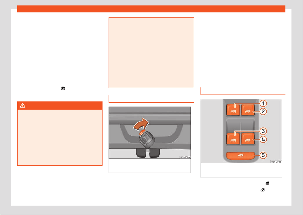
98
Opening and closing
●
If the rear bumper is very dirty.
●
If the rear bumper is wet with salt water, e.g.
aft
er having driven on gritted roads.
●
If the vehicle has been equipped at a later
time with a tow bracket.
In the event of heavy rain, the Easy Open fea-
ture may take a little longer to open the boot
or may deactivate automatically, to avoid the
boot opening by accident, e.g. because of the
running water.
The Easy Open function can be connected and
disconnected permanently in the infotainment
system using the button
> Settings > Open-
ing and cl
osing.
WARNING
If there is a valid key in the proximity of the
r
ear lid, in some cases the Easy Open func-
tion may be accidentally activated and the
rear lid will open, for example, when sweep-
ing under the rear bumper, when directing a
water jet or high pressure steam to the area
or when carrying out maintenance work or
repairs in that area. If accidentally opened,
the rear lid could injure somebody situated in
its area of operation or cause material dam-
age.
●
Therefore, always make sure that there is
no unsupervised valid key in the area near
the rear lid.
●
Before carrying out any maintenance or re-
pair work on the vehicle, always disable the
Easy Open feature via the infotainment sys-
tem.
●
Before washing the vehicle, always disable
the Easy Open function via the infotainment
system.
●
Before attaching a bike rack or hitching a
trailer ›››page297, always disable the Easy
Open function via the infotainment system.
Emergency unlocking of the rear lid
Fig.79 L
uggage compartment: manual
release.
The rear lid can be unlocked from inside in the
e
vent of an emergency (e.g. if the 12 volt bat-
tery is flat).
There is a groove in the luggage compartment
all
owing access to the emergency opening
mechanism.
Unlocking the rear lid from inside the lug-
gage compartment
●
Insert the key blade into the slot and move the
key in the direction of the arrow until the lock
unlocks ›››Fig.79.
Window controls
Opening and closing the windows
Fig.80 Det
ail of the driver door: controls for
the windows.
●
Opening the window: press button
●
Closing the window: pull button
Opening and closing
99
Window controls
1
2
3
4
5
Buttons on the driver door
Window on the front left door
Windo
w on the front right door
Window on the rear left door
Window on the rear right door
Safety switch for deactivating the electric
window buttons in the rear doors.
The front and rear electric windows can be op-
erated by using the controls on the driver door.
The other doors each have a switch for their
own window.
Always close the windows fully if you park the
vehicle or leave it unattended ›››
.
Y
ou can use the electric windows for approx. 10
minutes after switching o the ignition if neither
the driver door nor the front passenger door
have been opened and the ignition key has not
been removed (depending on the equipment).
Safety switch
The safety control ›››Fig.80
5
on the driver
door can be used t
o disable the electric win-
dow buttons on the rear doors.
Safety switch not pressed: buttons on rear
doors are activated.
Safety switch pressed: buttons on rear doors
are deactivated.
The safety control symbol
lights up in yellow
if the butt
ons on the rear doors are switched o.
Convenience open/close function
The electric windows can be opened or closed
from outside using the vehicle key:
Convenience opening:
●
Press and hold the
button on the remote
contr
ol key until all the windows and the sun-
roof have reached the desired position.
●
OR: First unlock the vehicle using the
button
on the r
emote control key and then keep the
key in the driver door lock until all the windows
and the sunroof have reached the required po-
sition.
Convenience closing:
●
Press and hold button
on the remote con-
tr
ol key until all the windows and the sunroof
are closed ›››
.
●
OR: K
eep the key in the driver door in the
"lock" position until all the windows and the
sunroof are closed.
●
OR: using the Keyless Access system (only
locking): Press and hold the locking sensor sur-
face ›››Fig.82 (arrow) on the door handle for
several seconds to close the windows and the
sunroof. If you release the sensor surface, the
closing movement stops.
During convenience closing, first the windows
and then the sliding sunroof will be closed.
In the infotainment system dierent settings
can be adjusted using the function button
> Settings > Opening and closing
> Window operation > Convenience
opening.
One-t
ouch opening and closing
The one-touch automatic opening and closing
is used to open or close the windows com-
pletely. It will not be necessary to hold the but-
ton of the corresponding electric window.
For the automatic raising function: pull the but-
ton for the corresponding window upwards until
it reaches the second position.
For the automatic lowering function: push the
button for the corresponding window down-
wards until it reaches the second position.
Stop automatic movement: push or pull on the
button of the corresponding window.
Resetting one-touch opening and closing
If the 12-volt battery is disconnected or dis-
charged when the windows are not completely
closed, the electric window automatic raising
and lowering function deactivates and has to
be reset:
●
Switch the ignition on.
●
Close all windows and doors.
●
Pull the corresponding window button up-
wards and hold it in this position for a few sec-
onds.
100
Opening and closing
●
Release the button, pull it up again and hold it
in this position. This r
esets the automatic raising
and lowering function.
The function can be reset for a single window or
for several windows at the same time.
WARNING
Observe the safety warnings ››› in Intr
o-
duction on page92.
●
Incorrect use of the electric windows can
result in injury.
●
Never close the rear lid without observing
and ensuring it is clear, to do otherwise could
cause serious injury to you and third parties.
Make sure that no one is in the path of a win-
dow.
●
If the ignition is switched on, the electric
equipment could be activated with risk of in-
jury, for example, in the electric windows.
●
The doors can be locked using the remote
control key. This could become an obstacle
for assistance in an emergency situation.
●
Therefore always take the key with you
when you leave the vehicle.
●
The electric windows will work until the ig-
nition has been switched o and one of the
front doors has been opened.
●
If necessary, use the safety switch to disa-
ble the rear electric windows. Make sure that
they have been disabled.
●
For safety reasons, you should only use
the remote control open and close functions
within about 2 metres of the vehicle. To avoid
injuries, always keep an eye on the windows
when pressing the button to close them. The
windows stop moving as soon as the button is
released.
Note
If the window is not able to close because
it is sti or because of an obstruction,
the windo
w will automatically open again
›››page100. If this happens, check why the
window could not be closed before attempt-
ing to close it again.
Window anti-trap function
The roll-back function reduces the risk of injury
when the electric windows close.
If a window encounters resistance or an obsta-
cle when closing, it will reopen immediately
›››
.
●
Check why the window does not close.
●
Try closing the window again.
●
If the closing process is interrupted again, the
anti-tr
ap function stops working for a few sec-
onds.
●
If the window still cannot be closed, it will stop
in the corresponding position. Pulling the button
again within a few seconds closes the window
without the anti-trap function ›››
.
Closing the windows without the anti-trap
function
●
Try to close the window again by pulling the
butt
on without releasing it, within a few sec-
onds. The anti-trap function will be deacti-
vated!
●
If the closing process takes longer than a
few seconds, the anti-trap function is activated
again. The window will stop again if it encoun-
ters resistance or an obstacle, and will reopen
automatically.
●
If the window will still not close, visit a special-
ised workshop.
WARNING
Observe the safety warnings ››› in Open-
ing and cl
osing the windows on page100.
●
The roll-back function does not prevent
fingers or other parts of the body getting
pinched against the window frame. Risk of
accident.
Note
The anti-trap function also works when the
windo
ws are closed with the comfort func-
tion using the vehicle key.
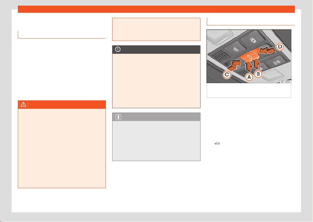
Opening and closing
101
Sunroof
Sunroof
Intr
oduction
The sunroof consists of two glass parts. The
rear part is fixed and cannot be opened. It also
has a sun blind.
The sunroof only works when the ignition
is switched on. Once the ignition has been
switched o, you can still open or close the
sunroof for a few minutes provided the driver
door and the front passenger door are not
opened.
WARNING
If the sunroof is used negligently or without
paying due attention, it can cause serious
injury.
●
Open or close the sunroof and the sun
blind only when no one is in their path of
movement.
●
Never leave any key inside the vehicle
when exiting.
●
Never leave a child or any other person
who may need help in the vehicle, especially
if they have access to the vehicle key. If using
they key unattended, they could lock the ve-
hicle, start the engine, switch on the ignition
and activate the sunroof.
●
After switching o, it is still possibl
e to
open or close the sunroof during a short
space of time provided that neither the driver
nor passenger door is opened.
NOTICE
●
To prevent damage, during winter tempera-
t
ures remove any ice or snow that might be
on the car roof before opening the sunroof or
adjusting the tilt position.
●
Before leaving the vehicle or in case of
rainfall, always close the sunroof. With the
sunroof open or in a tilted position, water can
enter the interior and can cause considera-
ble damage to the electrical system. As a re-
sult, other damage can occur in the vehicle.
Note
●
Leaves and other loose objects that accu-
mulate on the sunroof rails should be regu-
larly cleaned away either by hand or with a
vacuum.
●
If the sunroof does not work correctly, the
anti-trap function will not work either. Con-
tact a specialised workshop.
Operating the sunroof
Fig.81 On the int
erior roof lining: sunroof
button.
The sun blind automatically opens along with
the sunr
oof if completely closed or if in front of
the sunroof. The sun blind remains in the previ-
ous position and does not automatically close
with the sunroof. The sun blind can only be
closed completely once the sunroof has been
closed.
The
›››Fig.81 butt
on has two levels. The first
level switches the sunroof to the tilted position,
opening or closing it fully or partially.
On the second level, the sunroof automatically
moves to the corresponding final position after
briefly pressing the button. Activating the but-
ton again stops the automatic function.
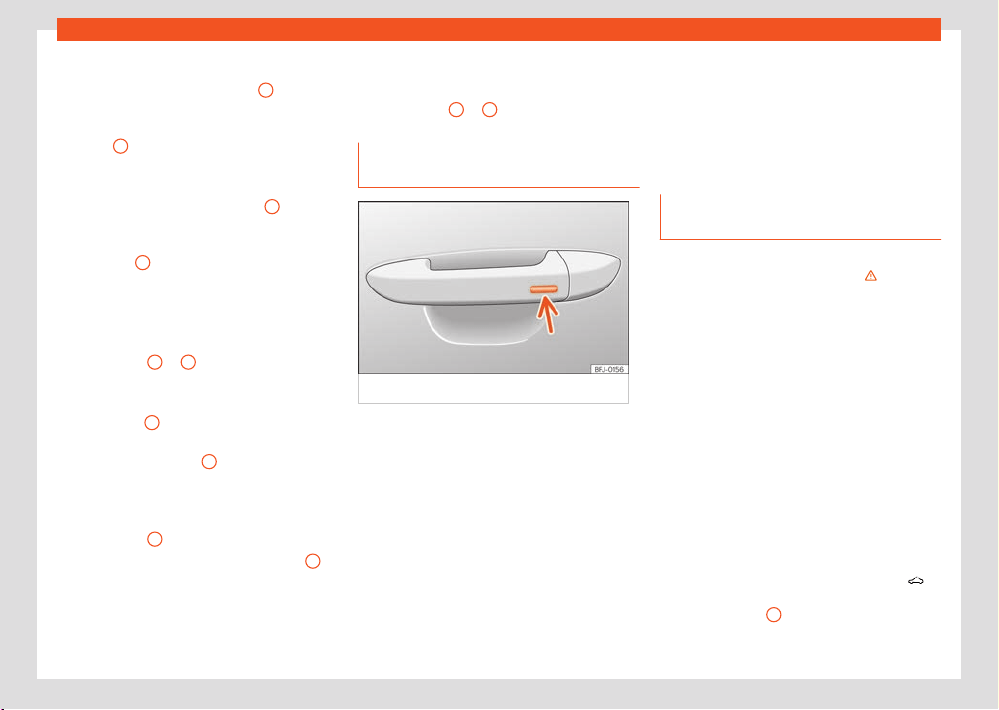
102
Opening and closing
Adjusting the tilt position of the sunroof
●
Press the rear part of the button
B
to the first
l
evel.
●
Automatic function: briefly press the rear part
of button
B
to the second level.
Cl
osing the sunroof from a tilted position
●
Press the front part of the button
A
to the
first l
evel.
●
Automatic function: briefly press the front part
of the button
A
to the second level.
St
opping the automatic operation by adjust-
ing the tilted position of the sunroof or by
closing the sunroof
●
Press button
A
or
B
again.
Opening the sunr
oof
●
Press button
C
backwards to the first l
evel.
●
Automatic function to the convenience posi-
tion: briefly press button
C
backwards to the
second l
evel.
Closing the sunroof
●
Press button
D
forwards to the first l
evel.
●
Automatic function: briefly press button
D
forwards to the second level.
Stopping the automatic operation during the
opening or cl
osing
●
Press button
C
or
D
again.
Conv
enience function to open or
close the sunroof
Fig.82 Door handl
e: sensor surface.
The sunroof can be opened and closed with the
conv
enience function, just like the windows.
Using the door lock
●
Hold the key in the door lock of the driver
door in either the unlocking or locking position
to open or close the roof in the tilted position.
Release the key to interrupt this function.
Using the remote control
●
Keep the locking or unlocking button pressed
to open or close the roof. If you release the
button is the opening or closing will stop.
Using the Keyless Access system (only lock-
ing)
Pr
ess and hold the locking sensor surface
›››Fig.82 (arrow) on the door handle to close
the sunroof. If you release the sensor surface,
the closing movement stops.
Anti-trap function of the panoramic
sunroof
The anti-trap function can reduce the risk of
injury when closing the sunroof ›››
. If the
sunr
oof encounters resistance or an obstacle
when closing, it reopens immediately.
●
Check why the sunroof did not close.
●
Try to close the sunroof again.
●
If the sunroof cannot be closed due to an
obstacle or some resistance, it stops at the
corresponding position and then reopens. For
automatic closing, a new closing attempt might
take place.
●
If the sunroof is still unable to close, close it
without the anti-trap function.
Closing the sunroof without the anti-trap
function
●
Within approximately 5 seconds of having
activated the roll-back function, press the
›››Fig.81 butt
on to the second level in the
direction of arrow
D
until the sunroof closes
compl
etely.
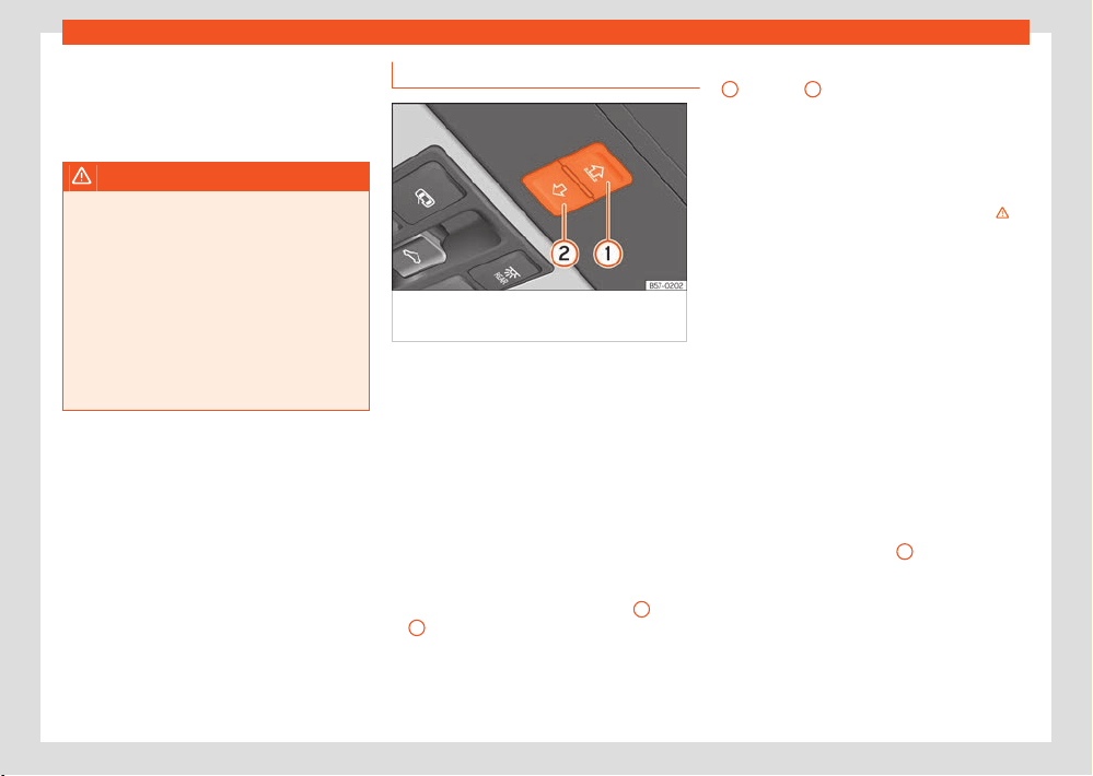
Opening and closing
103
Sunroof
●
The sunroof closes without the anti-trap
function int
ervening!
●
If the sunroof will still not close, visit a special-
ised workshop.
WARNING
Closing the sunroof without the anti-trap
function can cause serious injuries.
●
Always be careful when closing the sun-
r
oof.
●
No person should ever remain in the way of
the sunroof, especially when closing without
the anti-trap function.
●
The anti-trap function does not prevent fin-
gers or other parts of the body from becom-
ing trapped against the roof frame and inju-
ries occurring.
Glass roof sun blind
Fig.83 On the int
erior roof lining: function
button to operate the sun blind.
The electrical sun blind works when the ignition
is s
witched on.
When the sunroof is in its most tilted position,
the sun blind automatically goes into a ventila-
tion position. The sun blind remains in this posi-
tion also with the sunroof closed.
Once the ignition has been switched o, you
can still open or close the sun blind for a few
minutes provided the driver door and the front
passenger door are not opened.
Opening and closing the sunshade blind
●
Manual operation: press the button
1
(open)
or
2
(close) up to the first l
evel until the curtain
reaches the desired position.
●
Automatic operation: briefly pr
ess the button
1
(open) or
2
(close) up to the second level.
Pr
essing the button again stops the automatic
function.
Anti-trap function of the sunshade blind
The anti-trap function can reduce the risk of
injury when closing the sunshade blind ›››
. If
the blind encount
ers resistance or an obstacle
when closing, it will reopen immediately.
●
Check why the blind did not close.
●
Try to close the blind again.
●
If the blind still cannot be closed due to an
obstacle or resistance, it will reopen immedi-
ately. Once open, it can be closed for a short
space of time without the anti-trap function.
●
If it is still not possible to close the blind, close
it without the anti-trap function.
Closing the sunshade blind without the anti-
trap function
●
Try to close the blind again.
●
If it still cannot be closed, within 5 seconds
press the button ›››Fig.83
2
until the blind
cl
oses fully. The blind closes without the in-
tervention of the anti-trap function!
●
If it is still not possible to close the blind, visit a
specialised workshop.
104
Opening and closing
WARNING
Closing the sun blind without the anti-trap
function can cause serious injury.
●
Always close the blind with care.
●
Do not allow anyone to remain in the blind
tr
avel area, particularly when closing with-
out the anti-trap function.
●
The anti-trap function does not prevent fin-
gers or other parts of the body from becom-
ing trapped against the roof frame and inju-
ries occurring.
Note
When the sunroof is open, the electric sun
blind can only be cl
osed to the front edge of
the sunroof.
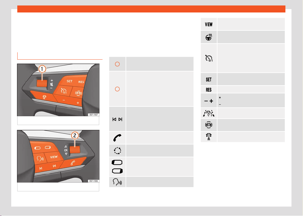
Steering wheel
105
Multifunction steering wheel
Steering wheel
Multifunction st
eering
wheel
Functions
Fig.84 Contr
ols on the steering wheel.
Fig.85 Contr
ols on the steering wheel.
The steering wheel includes multifunction mod-
ul
es from where it is possible to control the
audio, telephone, navigation, voice control and
assist functions without the driver needing to be
distracted from the road.
Buttons available depending on the version
1
Turn: T
urn volume up/down.
Press: Mute volume.
2
Turn: Sear
ch in the instrument panel
menu. In Navigation mode, turn to zoom
in/out of the map in the instrument clus-
ter.
Press: Select the highlighted option in
the instrument cluster
Radio: Sear
ch for the previous/next sta-
tion.
Media: Short press: previous/next track;
long press: fast forward/rewind.
Activate phone menu (answer call, end
call).
Switch between media and radio sour-
ces.
Change the instrument panel menu
(pr
evious/next).
Enable/disable voice control.
Change instrument cluster views
›››page16
Activate or deactivate steering wheel
heating ›››page138
Switching ACC on or o
›››page185 / Cruise contr
ol
›››page182 / Speed limiter
›››page184 / Travel Assist
›››page198.
Activate ACC / Travel Assist / Speed lim-
it
er
Reset programmed speed.
: Increase programmed speed.
: Decrease programmed speed.
Select Travel Assist / ACC.
Open the driver assistants menu in the
instrument clust
er.
Modify the programmed ACC distance.
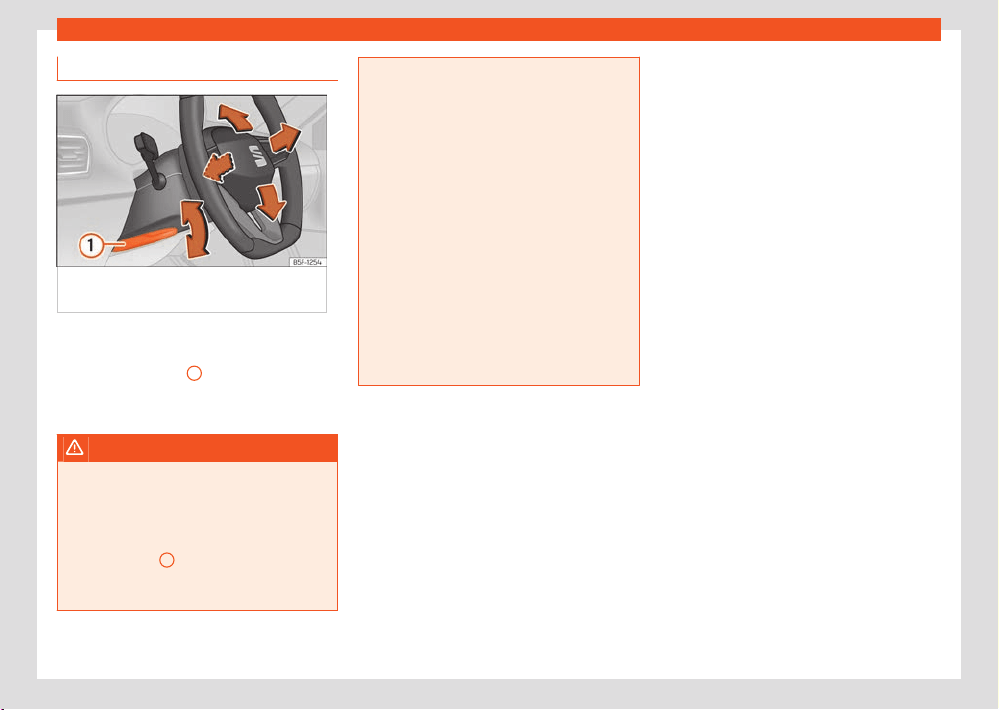
106
Steering wheel
Steering wheel position adjustment
Fig.86 L
ever in the lower left side of the
steering column.
Adjust the steering wheel before your trip and
only when the v
ehicle is stationary.
●
Pull lever ›››Fig.86
1
down, move the steer-
ing wheel t
o the desired position and lift the
lever back up until it locks.
WARNING
Incorrect use of the steering wheel adjust-
ment function and an incorr
ect adjustment
of the steering wheel can result in severe or
fatal injury.
●
After adjusting the steering column, push
lever ›››Fig.86
1
firmly up
wards so that the
steering wheel does not accidentally change
position while driving.
●
Never adjust the steering wheel while the
v
ehicle is in motion. If you need to adjust the
steering wheel while the vehicle is in motion,
stop safely and make the proper adjustment.
●
The adjusted steering wheel should be fac-
ing your chest and not your face so as not to
hinder the driver's front airbag protection in
the event of an accident.
●
When driving, always hold the steering
wheel with both hands on the outside of the
ring at the 9 o'clock and 3 o'clock positions
to reduce injuries when the driver's front air-
bag deploys.
●
Never hold the steering wheel at the 12
o'clock position or in any other manner (e.g.
in the centre of the steering wheel). In such
cases, if the driver's airbag deploys, you
may sustain injuries to your arms, hands and
head.

Seats and head restraints
107
Front seats
1
2
3
4
Seats and head re-
str
aints
Front seats
Introduction
WARNING
Always read and observe the informa-
tion and saf
ety advice given in chapter
›››page39, Correct sitting position of vehi-
cle occupants.
WARNING
Incorrect seat adjustment may lead to acci-
dents and se
vere injuries.
●
Only adjust the seats when the vehicle
is stationary, as the seats could move unex-
pectedly while the vehicle is in motion and
you could lose control of the vehicle. Further-
more, an incorrect position is adopted when
adjusting the seat.
●
Adjust the height, position and inclination
of the front seats only when their movement
area is empty.
●
Make sure there are no objects in that area.
●
Make sure that the movement and locking
areas of the seats are clean.
WARNING
Incorrectly using upholstery and seat cov-
ers might cause an accident
al activation of
the electrical seat adjustment system and
make it move unexpectedly while driving.
This might cause loss of control of the vehi-
cle and thus accidents or injuries. Moreover,
the electrical components of the front seats
might be damaged.
●
Never attach or place seat upholstery or
covers on the electric controls.
●
Never use upholstery or seat covers that
have not been explicitly authorised for the
seats of the vehicle.
NOTICE
Objects with sharp edges can damage the
seats.
●
Do not rub the seats with sharp objects.
Sharp ob
jects, such as zips and rivets on
clothing or belts, can damage surfaces.
Open Velcro fasteners can also cause dam-
age.
Manual adjustment of the front seats
Fig.87 Fr
ont seats: manual seat adjustment.
Pull the lever to move the seat forwards or
backw
ards. The seat must engage when
the lever is released!
Move the lever up or down to adjust the
seat height; several times if necessary.
Without placing force on the seat backrest,
turn the wheel to adjust the backrest.
To adjust the lumbar support, move the
lever until the required position is achieved.
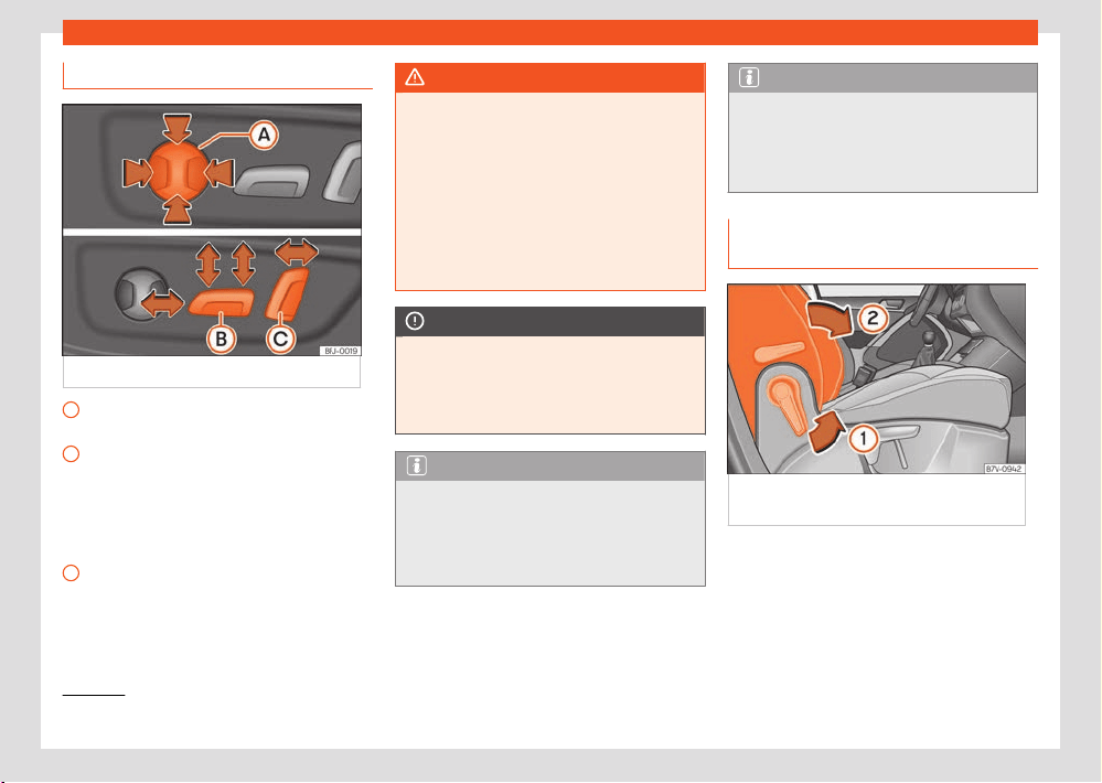
108
Seats and head restraints
1)
Valid for vehicles fitt
ed with the Infotainment Connect System.
A
B
C
Electric adjustment of the front seats
Fig.88 Driv
er's seat: electric seat adjustment.
Adjust the lumbar support: press the button
accor
ding to the desired position.
Seat forwards/backwards: press the button
forwards/backwards.
Seat up/down: Press the rear part of the
button up/down. To adjust the angle of the
seat cushion, press the front of the button
up/down.
Backrest further upright/further reclined:
press the button forwards/backwards.
The position will be saved automatically in the
SEAT Connect Active user when the ignition is
switched o
1)
.
WARNING
If the electric front seats are used negli-
gently or without paying due att
ention, it can
cause serious injury.
●
The front seats can also be electrically ad-
justed when the ignition is switched o. Never
leave a child or any other person who may
need help in the vehicle.
●
In the event of an emergency, electrical
adjustment can be stopped by pressing any
control.
NOTICE
To avoid damaging the electrical compo-
nents of the seats, pl
ease refrain from kneel-
ing on the seat or applying sharp pressure at
a single point to the seat cushion and back-
rest.
Note
●
It may not be possible to electrically adjust
the seat if the vehicle battery is very low.
●
If the engine is started while the seats are
being electrically adjusted, the adjustment
will stop.
Note
When changing user a warning will be shown
on the inf
otainment system's screen during
the time that the seat is moving to the saved
position. This movement can be stopped by
pressing the stop button on the screen.
Adjusting or folding the backrest of
the front passenger seat
Fig.89 P
assenger backrest: folding the
passenger backrest forward.

Seats and head restraints
109
Front seats
1)
In the FR version with sports seats, the backrest cannot be lowered.
Fig.90 Unl
ocking the folding backrest of the
front passenger seat
Adjusting the inclination of the front passen-
ger seat backr
est
●
Move the lever in the direction of the arrow
›››Fig.89
1
and adjust the backrest to the
desir
ed position.
Folding the backrest of the front passenger
seat forward
1)
●
Remove any objects from the front passenger
seat cushion ›››
.
●
Move the passenger seat to its lowest posi-
tion.
●
Move the front passenger seat back as far as
possibl
e.
●
Lower the head restraint properly.
●
Unlock the backrest of the front passenger
seat in the dir
ection of the arrow
1
.
●
Fold the backrest of the front passenger seat
f
orwards in the direction of the arrow
2
until it
is horiz
ontal.
●
Once folded down, the backrest has to be
locked safely.
When carrying objects on the folded down
backrest of the passenger seat, the front airbag
of this seat must be disabled ›››page52.
Lifting the backrest of the front passenger
seat
●
When lifting the passenger backrest, make
sure there are no objects or body parts within
the hinge movement area.
●
Lift the backrest of the front passenger seat
by first unlocking it again ›››Fig.90.
●
Lift the backrest of the seat in an upright posi-
tion.
●
Once it is raised again, the backrest must be
correctly engaged.
WARNING
Serious injuries can be caused if the passen-
ger seat backr
est is lowered or lifted without
due care and attention.
●
Only fold and lift the backrest of the front
passenger seat when the vehicle is station-
ary.
●
When folding down the passenger seat, al-
ways make sure there are no people or ani-
mals in the backrest area.
●
While the passenger backrest is down, the
front airbag must always be disabled and
the
warning lamp must be
on.
●
When moving the passenger backrest up
and do
wn, keep your hands, fingers, feet and
other body parts out of the operating area of
the hinges and the locking mechanism of the
seat.
●
Mats or other objects can be caught in the
hinges of the backrest of the front passenger
seat. This would cause the backrest not to be
locked in an upright position when lifting it.
●
Once the backrest is up, it must be cor-
rectly engaged in an upright position. Other-
wise, it could move unexpectedly and cause
severe injuries.
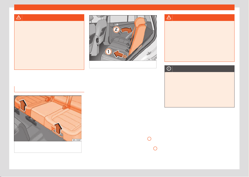
110
Seats and head restraints
WARNING
When folding down the passenger backrest,
its anchor points and hinges ar
e left uncov-
ered and may cause severe injuries in the
event of a sudden brake or accident.
●
When the passenger seat backrest is low-
ered nobody else can travel in the corre-
sponding seats (not even a child).
●
When the passenger seat backrest is low-
ered, the only permitted seat is the rear seat
behind the driver seat. This also applies to
children travelling on a child seat.
Rear seats
Adjusting the rear seat
Fig.91 Under the bench of the r
ear seat:
adjustment lever.
Fig.92 R
ear seat backrest adjustment.
The rear seat is asymmetrical and each part
can be adjust
ed separately.
Adjusting the rear seat
●
Pull the right or left lever upwards in the
dir
ection of the arrow ›››Fig.91, and move
the corresponding part of the seat forward or
backwards.
●
Release the lever and lock the seat, moving it
slightly to the front or the back.
Adjusting the rear seat backrest
●
Press the right or left backrest of the seat with
one hand and, at the same time, pull the corre-
sponding cord with the other ›››Fig.92
1
.
●
Move the backrest with your hand to the de-
sir
ed position; there will be some resistance
2
●
Release the cord and lock the backrest, mov-
ing it slightly t
o the front or the back.
WARNING
Incorrect backrest adjustment may lead to
accidents and se
vere injuries.
●
Only adjust the rear seat when the vehicle
is stationary; otherwise, it could move unex-
pectedly while the vehicle is in motion. Fur-
thermore, an incorrect position is adopted
when adjusting the seat.
●
Adjust the rear seat only when its move-
ment area is empty.
NOTICE
●
When moving the rear seat horizontally,
ob
jects in the luggage compartment might
cause damages.
●
When the seat is in its frontmost position,
objects can be stored between the seat and
the luggage compartment. Before moving
the seat backwards, remove any objects in
this area.
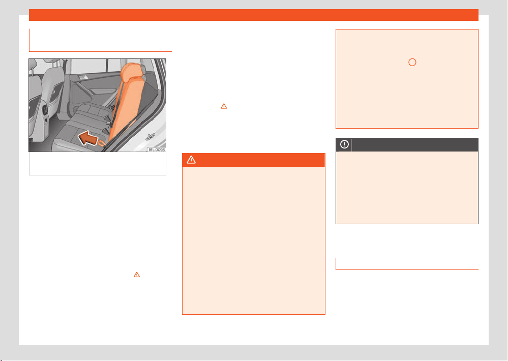
Seats and head restraints
111
Headrest
Folding down and raising the rear
seat backr
est
Fig.93 F
olding down and lifting the rear seat
backrest
The rear seat backrest is split and each part
be l
owered separately to extend the luggage
compartment.
Folding the backrest forwards
●
Fully lower the rear headrests ›››page112.
●
Move the rear seat to its rearmost position.
●
Pull the cord ›››Fig.93 forward in the direc-
tion of the arrow while holding the seat back-
rest and move it forward slowly›››
.
●
Press the backrest down with your hand until
it l
ocks.
Converting the table to a seat
●
Unlock the seat backrest with the cord. The
backr
est disengages from its position.
●
Without letting go of the cord, lift the back-
rest.
●
Make sure that the seat belt is not trapped.
●
Press the backrest firmly into the lock until it
engages ›››
.
●
The backrest must be properly engaged.
●
If necessary, adjust the backrest.
●
If necessary, adjust the head restraint.
WARNING
Serious injuries can be caused if the rear
seat backr
est is lowered or lifted without due
care and attention.
●
Never lower or lift the rear seat backrest
while driving.
●
Do no trap or damage the seat belt when
raising the rear seat backrest.
●
When lowering or lifting the rear seat back-
rest, keep your hands, fingers, feet and other
body parts out of its path.
●
For the rear seat belts to oer the nec-
essary protection all the parts of the rear
backrest must be properly engaged. This
is particularly important in the case of the
centre rear seat. If someone is seated in a
seat whose backrest is not properly engaged
they will fly forward, along with the backrest,
during an accident or a sudden driving or
braking manoeuvre.
●
A red mark on button
2
warns that the rear
backr
est is not engaged. Always check that
the red marking is not visible when the back-
rest is in the upright position.
●
When the rear seat backrest is lowered or
is not properly engaged nobody else can
travel in the corresponding seats (not even
a child).
NOTICE
Serious damage can be caused to the vehi-
cl
e and other objects if the rear seat back-
rest is lowered or lifted without due care and
attention.
●
Before lowering the rear seat backrest, al-
ways adjust the front seats so that neither
the head restraints nor the cushions of the
rear backrest can hit them.
Headrest
Introduction
The possibilities for the adjustment and disas-
sembly of the headrests are described below.
Always make sure that the seats are correctly
adjusted ›››page39.
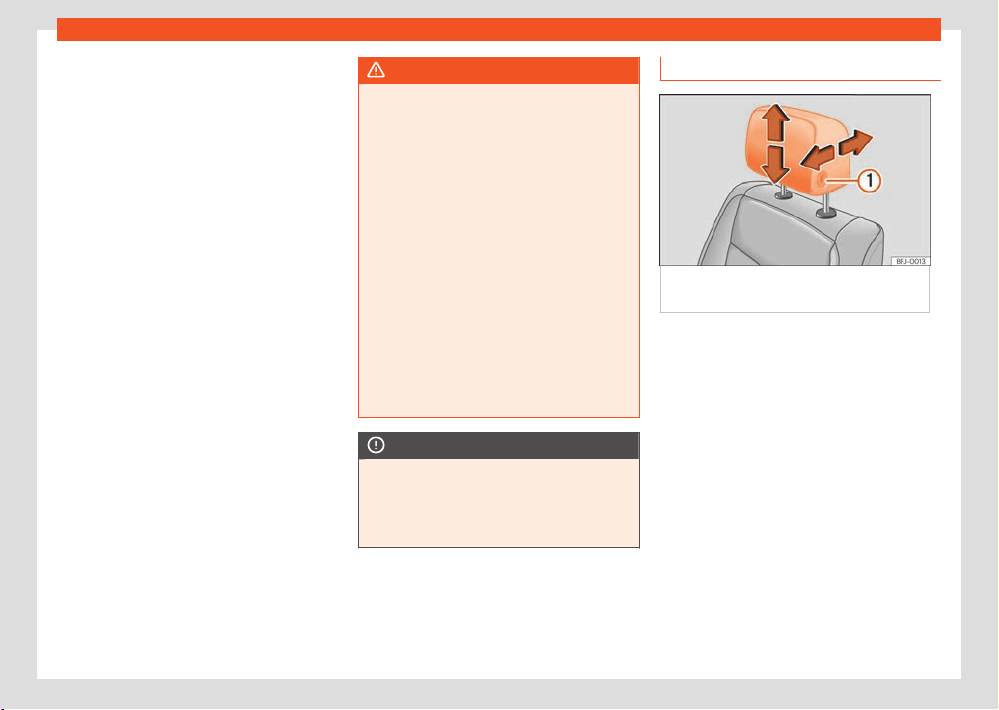
112
Seats and head restraints
All seats are equipped with a head restraint.
The r
ear headrests have been designed exclu-
sively for the corresponding seat of the second
or third row. Therefore, never mount them on
any other seat.
Correct adjustment of head restraint
Adjust the headrest so that its upper edge is
at the same level as the top of your head and
under no circumstances below eye level. Keep
the back of your head always as close to the
head restraint as possible.
In vehicles with horizontally adjustable head re-
straints on the front seats, move the head re-
straint as close as possible to the back of the
head.
Adjusting the head restraint for short people
Lower the head restraint completely, even if
your head is below its upper edge. In the low-
est position, there may be a small distance be-
tween the head restraint and the backrest.
Adjusting the head restraint for tall people
Push the head restraint up as far as it will go.
WARNING
If travelling with the head restraints removed
or impr
operly adjusted, the risk of severe or
fatal injuries in the event of accidents and
sudden braking or manoeuvres increases.
●
Always travel with the head restraint cor-
rectly installed and adjusted.
●
To decrease the risk of cervical injuries in
the event of an accident, adjust the head
restraint correctly based on your height, al-
ways making sure that its upper edge is at
the same height as the top of the head, but
never below eye level. Keep the back of your
head always as close to the head restraint as
possible and centred.
●
Never adjust the head restraint while the
vehicle is in motion.
●
Under no circumstances should the rear
passengers travel while the head restraints
are in the non-use position.
NOTICE
When assembling and disassembling the
head r
estraints, do not let them meet the top
lining of the vehicle, the back rest of the front
seat or other parts of the vehicles. If not, this
could damage the vehicle.
Adjusting the headrests
Fig.94 Fr
ont seat: adjusting the head
restraint.
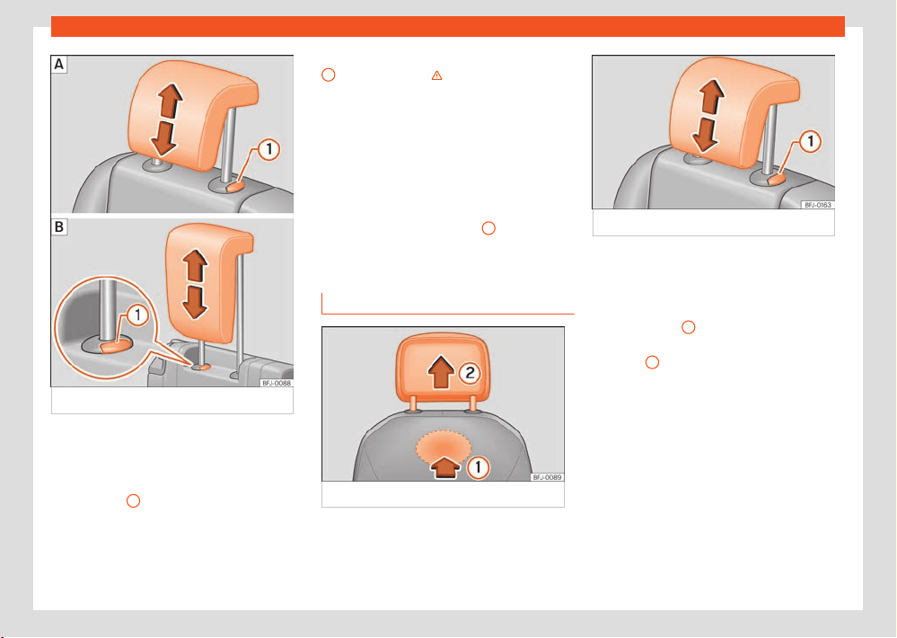
Seats and head restraints
113
Headrest
Fig.95 R
ear headrest: adjusting the headrest.
Adjusting the height of the head restraints
●
Move the headrest up or down in the direction
of the corr
esponding arrow. Regarding the rear
headrest, to both raise and lower, press the but-
ton ›››Fig.94
1
; for the rear headrests it is
only necessary to press the button ›››Fig.95
1
to lower them ›››
in Intr
oduction on
page112.
●
The headrest must lock correctly in one posi-
tion.
Adjusting the front head restraints horizon-
tally
●
Move the head restraint forward or back in
the direction of the corresponding arrow while
pressing the button ›››Fig.94
1
.
●
The headrest must lock correctly in one posi-
tion.
R
emoving and fitting the headrests
Fig.96 Fr
ont head restraint: removal.
Fig.97 R
ear head restraint: removal.
Removing the front head restraints
●
Lower the head restraint if necessary.
●
To unlock it, look for the rabbet on the bottom
of the backr
est and press in the direction of the
arrow ›››Fig.96
1
.
●
Remove the head restraint in the direction of
the arr
ow
2
.
Fitting the fr
ont head restraints
●
Place the head restraint in the correct posi-
tion on the guides of the corresponding back-
rest and insert it.
●
Press the head restraint downwards until the
bars lock.
●
Adjust the head restraint according to the in-
structions on the correct position of the seat.
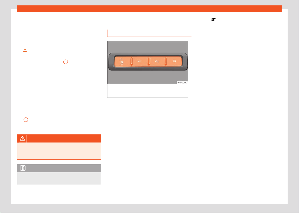
114
Seats and head restraints
Removing the headrests from the second
r
ow of seats
●
If necessary, adjust the backrest of the seat
so the head restraint can be removed.
●
Push the head restraint up as far as it will go
›››
in Intr
oduction on page112.
●
Remove the head restraint completely while
pressing button ›››Fig.97
1
.
Inst
alling the headrests of the second row of
seats
●
Unlock the rear seat backrest and fold it for-
ward slightly ›››page110.
●
Place the head restraint in the correct posi-
tion on the guides of the corresponding back-
rest and insert it.
●
Lower the head restraint while pressing but-
ton
1
.
●
Raise the rear seat backrest and lock it.
WARNING
Remove the rear headrests only when it is
necessary t
o fit a child seat. After removing a
child seat, refit the headrest immediately.
Note
The headrests of the third row of seats can-
not be r
emoved.
Seat functions
Memory function
Fig.98 On the out
er side of the driver seat:
memory buttons.
Memory buttons
Individual settings f
or the corresponding seat
can be stored with the memory buttons. Addi-
tionally, settings for the exterior mirrors can be
saved with the memory buttons of the driver
seat.
The settings will also be saved in the key or in
the user of the online services, depending on
the version.
Save the settings of the driver seat and the
exterior mirrors while driving forward
●
Apply the electronic parking brake.
●
Move the gearshift to the neutral position.
●
Switch the ignition on.
●
Adjust the driver seat and the exterior mirrors.
●
Press
for longer than 1 second ›››Fig.98.
●
Press the memory button in which to store the
settings within appr
ox. 10 seconds. A warning
sound will confirm they have been stored.
Storing the passenger rear view mirror set-
tings while driving in reverse
●
Apply the electronic parking brake.
●
Move the gearshift to the neutral position.
●
Switch the ignition on.
●
Press the required memory button.
●
Select reverse gear.
●
Adjust the front passenger exterior mirror so
that you can see, for example, the kerb edge
well.
●
The new position of the mirror will be stored
automatically and allocated to the vehicle key
that was used to unlock the vehicle.
Activating settings
●
With the vehicle stopped and the ignition
switched on, press and hold the correspond-
ing memory button until the saved position is
reached.
●
OR: With the ignition switched o and the
driver's door open, briefly press the corre-
sponding button.
The front passenger side exterior mirror auto-
matically changes from the position stored for
reversing as soon as the vehicle moves forward
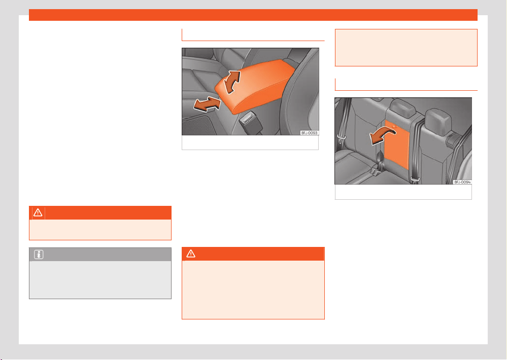
Seats and head restraints
115
Seat functions
at a speed of at least 15km/h (10mph) or when
the gear sel
ection lever is changed to a position
other than R ›››page129.
Initialising the seat position memory
The position memory system must be restar-
ted if, for example, the driver seat has been
changed.
Restarting deletes all memories and assign-
ments for the seat with position memory. The
memory keys can then be programmed again.
●
Open the driver door and do not get into the
vehicle.
●
Operating the seat settings from outside the
vehicle.
●
Tilt the backrest fully forward.
●
Release the control to set the angle and then
press again until an audible warning is heard.
WARNING
Adjust the memory function only when the
v
ehicle is stationary.
Note
If the driver door is opened approx. 10 mi-
nut
es after the vehicle was unlocked or later,
the driver seat and the exterior mirrors do not
move automatically.
Front centre armrest
Fig.99 Fr
ont centre armrest
To r
aise the armrest, pull it fully up in the direc-
tion of the arrow ›››Fig.99 up or step by step
depending on the desired opening.
To lower the armrest, first lift it to its highest
position. Then lower it down.
To move the armrest horizontally, move it for-
ward ›››Fig.99 or backward as much as possi-
ble in the direction of the corresponding arrow.
WARNING
The front centre armrest may obstruct the
driv
er's arm movements, which could cause
an accident and severe injuries.
●
Keep the storage compartments of the
centre armrest closed at all times while the
vehicle is in motion.
●
Never let anyone sit on the centre arm-
r
est while the vehicle is in motion, not even
a child. This position is incorrect and may
cause severe injuries.
Rear centre armrest
Fig.100 F
olding rear centre armrest.
There might be a folding armrest in the rear
centr
e seat.
●
To lower the armrest, pull the cord in the di-
rection of the arrow ›››Fig.100.
●
To raise the armrest, push it up in the opposite
direction to the arrow and press it as far as it
will go into the seat backrest.
When the centre armrest is down, do not allow
anybody to travel in the centre seat of the rear
bench.
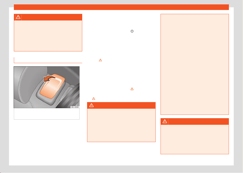
116
Seats and head restraints
WARNING
To decrease the risk of injuries while driv-
ing, the r
ear centre armrest must always be
raised.
●
When the centre armrest is down, nobody
may travel in the centre rear seat, not even a
child. An incorrect sitting position may cause
severe injuries.
Access aid for the third row of seats
Fig.101 Second seat r
ow: accessibility
controls.
The convenient entry function makes it easier to
access the thir
d row of seats.
Folding down the backrest and moving the
second r
ow seat
●
Remove any objects located in the footwell
of the second row of seats ›››
.
●
Pull the release lever in the direction of the
arr
ow ›››Fig.101.
●
Fold down the backrest of the seat and move
the seat forward.
●
Enter the vehicle or leave the vehicle care-
fully›››
.
F
olding down the second row backrest
●
Move the rear seat to its rearmost position.
●
Pull the lever ›››Fig.101 and push the back
-
rest backwards until it is in a vertical position.
The entire seat folds down›››
.
●
The rear seat must be correctly engaged
››› .
WARNING
If the convenient entry function is used negli-
gently or without due car
e, this may cause
accidents and serious injury.
●
Never use the convenient entry function
when the vehicle is in motion.
●
Avoid trapping or damaging the seat belt
when folding the rear seats back.
●
When moving the backrests up and down,
keep your hands, fingers, feet and other
body parts out of the operating area of the
hinges and the locking mechanism of the
seats.
●
Mats or other objects can be caught in
the hinges of the seat backrests or the seats
themselves. This would cause the backrests
and benches not to lock correctly when mov-
ing the seats to the vertical position.
●
For the rear seat belts to oer the neces-
sary protection all the parts of the rear back-
rest must be properly engaged vertically. If
someone is seated in a seat whose backrest
is not properly engaged they will be thrown
forwards, along with the backrest, during an
accident or a sudden driving or braking ma-
noeuvre.
●
When a rear seat or its backrest is folded
down or not correctly engaged, do not let
anyone use that seat, not even a child.
●
When going in and out of the vehicle, never
lean on or grab the tilted seat of the second
row.
WARNING
If all the seats on the second row are equip-
ped with chil
d seats, in the event of an acci-
dent the seats of the second row cannot be
pushed forwards from the third. People trav-
elling in the third row will not be able to leave
the vehicle or help themselves in the event of
an emergency.

Seats and head restraints
117
Seat functions
●
Whenever there are people in the third row,
do not inst
all child seats on all the second
row seats at the same time.
NOTICE
Before lowering and raising the rear seat
backr
est, adjust the front seats so that nei-
ther the head restraints nor the cushions of
the rear backrest can hit them.
NOTICE
Any objects located in the footwell of the
second row of seats may be damaged on
folding the rear seat forwards. Before folding
down the seats, remove the objects.
Unlock the seat backrest with the
cor
d.
Fig.102 In the luggage compartment: l
evers
to unlock the rear backrest.
●
Lower the head restraint properly.
●
Open the rear lid.
●
Pull the remote release lever of the left
›››Fig.102
1
or right
2
parts of the back-
r
est in the direction of the arrow. The released
part of the rear seat backrest is folded auto-
matically down and forwards.
●
If this occurs, close the rear lid.
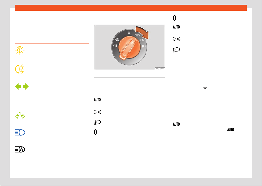
118
Lights
Lights
V
ehicle lighting
Control lamps
Lights up yellow
Ther
e is a total or partial failure of the
exterior lighting.
Lights up yellow
Rear fog light on.
Lights up green
Left or right turn signal. The control
lamp flashes twice as fast when a
turn signal is faulty.
Hazard warning lights on ›››page65.
Lights up green
Trailer turn signals
Lights up blue Main beam on or flasher
activ
ated ›››page120.
Lights up blue
The Light Assist system is on
›››page121.
Lights control
Fig.103 Instrument panel
: light panel.
Turning on the lights
●
Turn on the ignition and turn the light switch to
the desir
ed position ›››Fig.103:
Automatic control of dipped beam head-
lights and daytime running lights.
Side lights and daytime running lights on.
Dipped beam switched on.
Daylight running lights switched on.
Turning o the lights
●
Turn o the ignition and turn the light switch to
the desired position:
Lights o.
The “Coming home
”, “Leaving home” and
Welcome lights may be switched on.
Side light or parking light on both sides
on.
Dipped beam headlight o.
The driver is personally responsible for the cor-
rect use and adjustment of the lights in all situa-
tions.
Side lights
When the side light
is switched on, the side
lights in both headlights, cert
ain areas of the
rear light clusters, the number plate light and
the button lights on the instrument cluster turn
on. The automatic dipped beam activates as of
a speed of approx. 10 km/h (6 mph).
Automatic dipped beam headlight control
When the light control is in position , the
v
ehicle's lighting and the lighting of the instru-
ments and controls turn on and o under the
following conditions:
●
The light sensor has detected darkness.
●
The wiper has been on for some time.
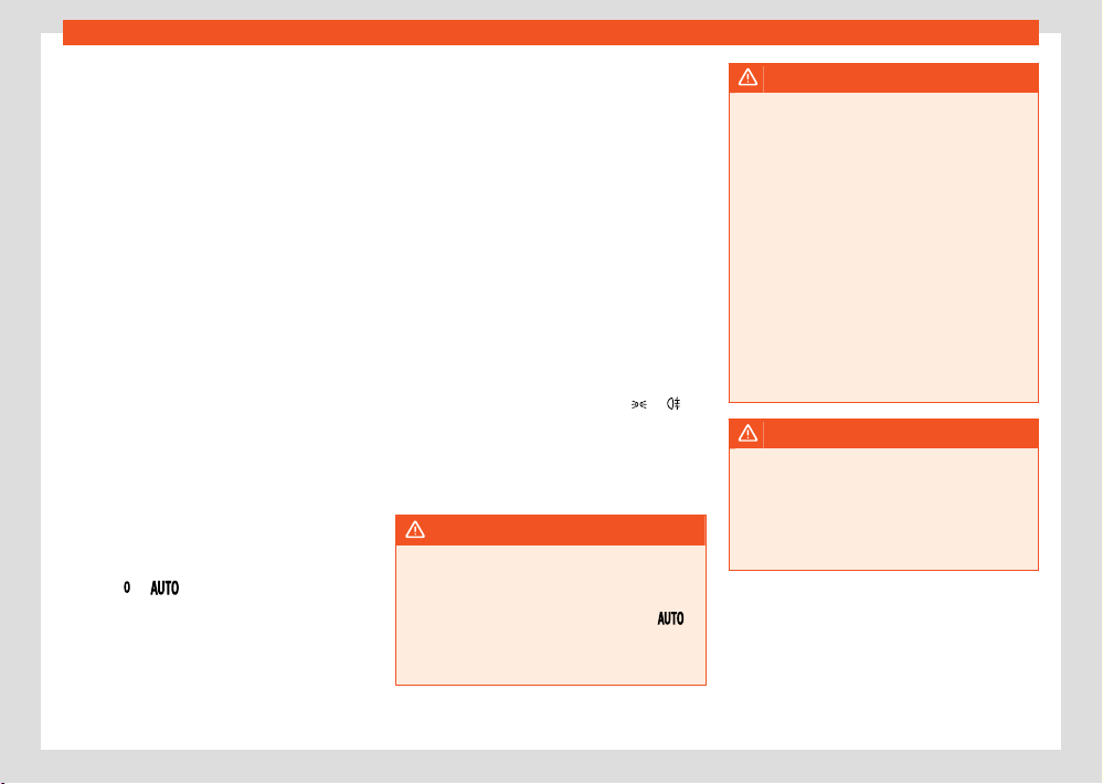
Lights
119
Vehicle lighting
The automatic dipped beam is only an auxili-
ary function and cannot al
ways identify all sit-
uations that may arise during driving with su-
cient precision.
Cornering light function
The cornering light function is an additional
function to the dipped beam headlights to im-
prove lighting of the side of the road when tak-
ing a sharp turn at low speed.
When the dipped beam is on, a static cornering
light comes on when driving at speeds below
about 40km/h (25mph) or on very tight bends.
●
If the steering wheel is turned or the turn sig-
nal is switched on, the front fog light gradually
turns on. After the turn, the cornering light func-
tion is gradually switched o.
●
When engaging reverse gear, both front fog
lights turn on.
Daytime running lights
Daytime running lights can increase vehicle vis-
ibility when driving during the day.
The daytime running lights switch on every time
the ignition is switched on, if the switch is in
positions
or , according to the level of
e
xterior lighting.
Motorway light
The function is connected and disconnected
via the corresponding Infotainment system
menu.
●
Activation: when going above 110km/h
(68mph) for more than 10 seconds, the dipped
beam raises slightly to increase the driver's visi-
bility distance.
●
Deactivation: when reducing the speed of
the vehicle below 100km/h (62mph), the dip-
ped beam immediately returns to its normal po-
sition.
Audible warnings to advise the driver that
the lights have not been switched o
If the ignition is not connected and the driver
door is open, an audible warning signal is heard
in the following cases: this will remind you to
turn the light o.
●
When the parking light is on ›››page120.
●
When the light switch is in position
or .
If the e
xit lighting is switched on (“Coming
Home” function), when you leave the vehicle
there will be no audio warning to warn you that
the lights are still on.
WARNING
If the road is not well lit and other road users
cannot see the v
ehicle well enough or at all,
accidents may occur.
●
The automatic dipped beam control (
)
only s
witches on the dipped beam when
there are no changes in brightness, and not,
for example when it is foggy.
WARNING
The side lights or daytime running lights
ar
e not bright enough to illuminate the road
ahead and to ensure that other road users
are able to see you.
●
Always use your dipped beam head lights if
it is raining or if visibility is poor.
●
Never drive with daytime lights if the road
is not well lit due to weather or lighting con-
ditions.
●
On vehicles with rear lights with bulbs,
when activating the daytime running light
the rear lights are not switched on. A vehicle
which does not have the rear lights on may
not be visible to other drivers in the darkness,
in the case of heavy rain or in conditions of
poor visibility.
WARNING
If the headlights are set too high and not
used corr
ectly, there is a risk of dazzling or
distracting other road users. This could result
in a serious accident.
●
Always make sure that the headlights are
correctly adjusted.
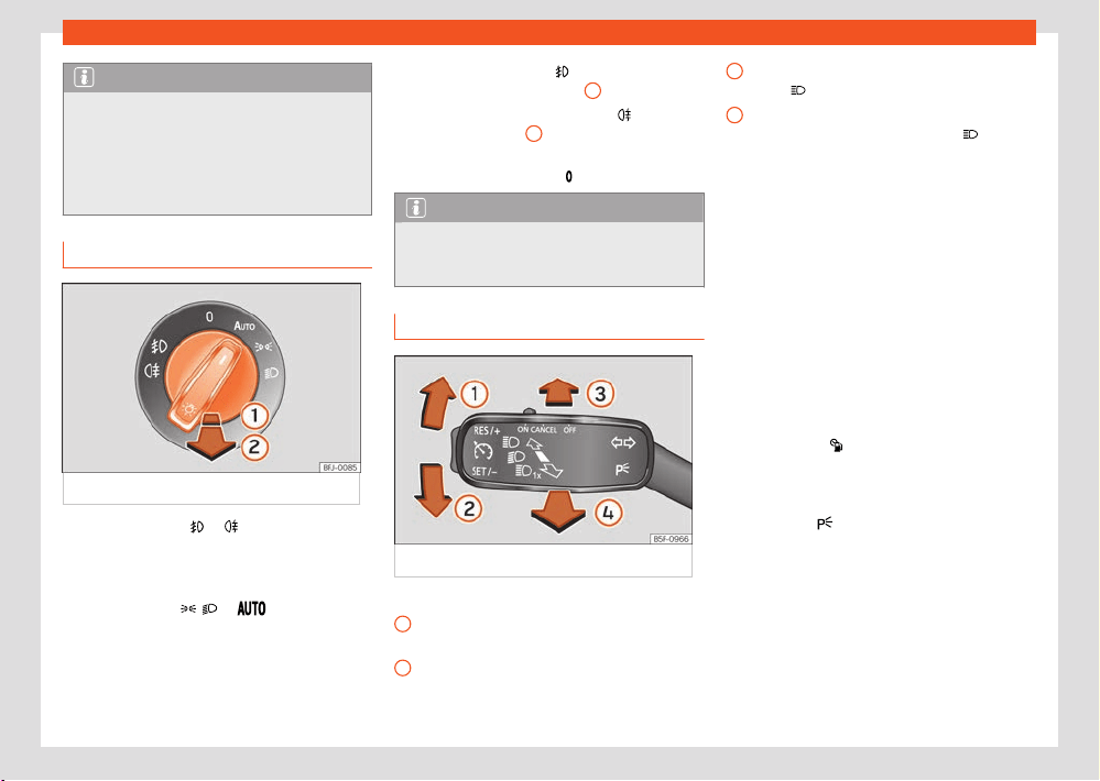
120
Lights
1
2
3
4
Note
●
The legal requirements regarding the use
of v
ehicle lights in each country must be ob-
served.
●
The dipped beam headlights will only work
with the ignition on. The side lights come on
automatically when the ignition is turned o.
Fog lights
Fig.104 Instrument panel
: light panel.
The warning lamps
or also show, on the
light s
witch or instrument panel, when the fog
lights are on.
The fog lights can be switched on with the light
control in position
, or when the igni-
tion is s
witched on:
●
Turn on the fog lights
: pull the light s
witch
to its first position ›››Fig.104
1
.
●
Switching on the rear fog light
: pull the
light s
witch fully out
2
.
●
To switch o the f
og lights, press the light
switch or turn it to position
.
Note
The rear fog light can dazzle drivers behind
you. Y
ou should use the rear fog light only
when visibility is very poor.
Turn signal and main beam lever
Fig.105 T
urn signal and main beam lever.
More the lever to the required position:
Right turn light or right-hand parking light
(ignition s
witched o).
Left turn light or left-hand parking light (ig-
nition switched o).
Turning on the main beam. The control
l
amp
lights up on the instrument cluster.
The headlight flasher t
urns on when the
lever is pulled. The control lamp
lights up
on the instrument clust
er.
Place the lever in rest position to turn o the
corresponding function.
Convenience turn signals
When the ignition is switched on, move the lever
as far as possible upwards or downwards and
release the lever. The turn signal will flash three
times.
To switch o the convenience turn signal early,
immediately move the lever in the opposite di-
rection until you feel resistance and release it.
The convenience turn signals are switched on
and o in the infotainment system using the
function button
> Settings > Lighting
> Lighting assistant > Convenience
turn signals.
P
arking light
The parking lights will only work with the igni-
tion o. If said light is on, an audibl
e warning will
sound while the driver door is open.
●
Switch the ignition o.
●
Move the turn signal lever up or down.
When the parking light is switched on, the front
side light and the tail light on the corresponding
side of the vehicle turn on.
Lights
121
Vehicle lighting
Parking light on both sides
●
Switch the ignition o.
●
Place the light switch in position .
●
Lock the vehicle from the outside.
In doing so
, only the side lights of both head-
lights light up, and additionally the tail lights will
do so partially.
WARNING
Improper or lack of use of the turn signals,
or f
orgetting to deactivate them can confuse
other road users. This could result in a seri-
ous accident.
●
Always give warning when you are going to
change lane, overtake or when turning, acti-
vating the turn signal in good time.
●
As soon as you have finished changing
lane, overtaking or turning, switch the turn
signal o.
WARNING
Incorrect use of the headlights may cause
accidents and serious injury, as the main
beam may distr
act or dazzle other drivers.
Note
●
When you turn the ignition o without hav-
ing t
urned the turn signals o, an acoustic
signal sounds while the driver door is open.
This is intended as a reminder to switch o
the turn signal, unless you wish to leave the
parking light on.
●
If the convenience turn signals are oper-
ating (three flashes) and the other conven-
ience turn signals are switched on, the active
part stops flashing and only flashes once in
the new part selected.
●
The turn signal only works when the igni-
tion is switched on. The hazard warning lights
also work when the ignition is switched o.
●
The main beam headlights can only be
switched on if the dipped beam headlights
are already on.
●
If a trailer turn signal malfunctions, the
control lamp will stop flashing (trailer turn
signals) and the vehicle turn signal will flash
at double speed.
●
In cold or damp weather conditions, the
headlights, tail lights and turn signals may
mist up inside temporarily. This is normal and
in no way eects the useful life of the vehicle
lighting system.
●
The parking light does not activate auto-
matically if the left- or right-hand turn signal
is left on and the ignition is disconnected.
Main beam assist (Light Assist)
The main beam assist automatically prevents
glare from vehicles moving in the opposite di-
rection or ahead in the same direction. In addi-
tion, the main beam assist detects illuminated
areas and disconnects the main beam head-
light when passing, e.g. by populated areas.
Within its limitations, the assist system automat-
ically connects or disconnects the main beam
headlight depending on the environmental and
trac conditions, as well as the speed ›››
.
Switching on the main beam assist
●
Turn on the ignition and turn the light switch to
position .
●
From the base position, press the turn sig-
nal and main beam headlights l
ever forwards
›››Fig.105
3
.
When the main beam assist is s
witched on,
the control lamp
on the instrument cluster
scr
een turns on. When the main beam is on, the
blue main beam control lamp
on the instru-
ment clust
er switches on.
Switching the main beam assist o
●
Turn the headlight switch to a position other
than
.
●
EITHER: if main beam assist is on, pull the t
urn
signal light and main beam headlights lever
back ›››Fig.105
4
.
122
Lights
●
OR: if the main beam assist
ant is on, but the
main beam does not turn on, press the turn
signal and main beam lever forwards to turn
the main beam on manually. Pull the turn signal
and main beam lever back to switch o the
main beam manually, if necessary.
●
OR: switch o the ignition.
System limitations
In the following cases, the main beam headlight
must be switched o manually because the
main beam assist will not disconnect it on time
or disconnect it at all:
●
On roads with insucient lighting with very
reflective signs
●
If road users are insuciently lit up, e.g. pe-
destrians or cyclists.
●
On closed curves, when the trac in the
opposite direction is partially hidden, on pro-
nounced slopes or inclinations.
●
On roads with trac in the opposite direction
and with a central reservation barrier where the
driver can see over it e.g. lorry drivers.
●
In the event of fog, snow or heavy rain
●
In the event of dust or sand storms
●
If the windscreen is damaged in the camera's
field of vision.
●
If the camera's field of vision is misted up, dirty
or covered by a sticker, snow or ice.
●
If the camera is damaged or if the power sup-
ply has been cut o.
WARNING
The convenience features of the main beam
assist shoul
d not encourage the taking of
risks. The system is not a replacement for
driver concentration.
●
You are always in control of the main beam
and adapting it to the light, visibility and
trac conditions.
●
It is possible that the main beam headlight
control does not recognise all driving situa-
tions and is limited under certain circumstan-
ces.
●
When the field of vision of the camera is
dirty, covered or damaged, operation of the
main beam control may be aected. This
also applies when changes are made to the
vehicle lighting system, for example, if addi-
tional headlights are installed.
NOTICE
To avoid aecting the oper
ation of the sys-
tem, take the following points into considera-
tion:
●
Clean the field of vision of the camera reg-
ularly and make sure it is free of snow and
ice.
●
Do not cover the field of vision of the cam-
era.
●
Check that the windscreen is not damaged
in the area of the field of vision of the cam-
era.
Note
●
The headlight flasher can be t
urned on and
o manually at any time with the turn signal
and main beam lever ›››page120.
●
If there are objects that radiate light in the
camer
a's area of influence, e.g. a portable
navigation system, this may aect the oper-
ation of the main beam assist system.
“Coming home” and “Leaving home”
function (exterior orientation light-
ing)
The “Coming home” and “Leaving home” func-
tion lights up the vehicle’s immediate surround-
ings when getting into and out of it in the dark.
This light is automatically controlled by a light
sensor.
Turning on the “Coming home” light
●
Unlocks the vehicle (if the light switch is in
position
and the light sensor detects dark-
ness).
T
urning o the “Coming home” light
●
It turns o automatically once the lights o
delay time has elapsed.
●
OR: lock the vehicle.
●
OR: rotate the light switch to position
.
●
OR: s
witch on the ignition.
Lights
123
Interior lights
Turning on the “Leaving home” light
●
Switch the ignition o.
The “L
eaving Home” light turns on if the light
control is in position
and the light sensor
det
ects darkness.
The lights-o delay countdown starts when the
last door or rear lid of the vehicle is closed.
Turning o the “Leaving home” light
●
It switches o automatically after the set
lights-o delay time has elapsed.
●
EITHER: it is automatically deactivated if, 30
seconds after the function has been activated,
any vehicle door or the rear lid is still open.
●
OR: rotate the light switch to position
.
●
OR: s
witch on the ignition.
Welcome light
The welcome light is a light located on the exte-
rior mirrors facing the ground which is switched
on or o if the lights control is in the
posi-
tion and the “Coming Home
” or “Leaving Home”
function is switched on or o.
“Coming home” and “Leaving home” set-
tings
The duration of the lights-o delay can be set
in the vehicle settings menu of the infotainment
system, where the function can also be activa-
ted and deactivated ›››page37.
Dynamic headlight range control
The headlight r
ange is automatically adjusted
according to the vehicle load status when they
are switched on.
WARNING
If the dynamic headlight range control fails
or does not w
ork properly, the headlights
could dazzle and distract other road users.
This could cause accidents and lead to seri-
ous injuries.
●
Immediately go to a specialist workshop
and have the headlight range control system
checked.
Driving abroad
The light beam of the dipped beam lights is
asymmetric: the side of the road on which you
are driving is lit more intensely.
When a car that is manufactured in a country
that drives on the right travels to a country that
drives on the left (or vice versa), it is normally
necessary to cover part of the headlight bulbs
with stickers or to change the adjustment of the
headlights to avoid dazzling other drivers.
In such cases, the regulations specify certain
light values that must be complied with for des-
ignated points of the light distribution. This is
known as “Tourist light”.
The light distribution of the headlights allows
the specific “t
ourist light” values to be met
without the need for stickers or changes being
made to the settings.
Note
“Tourist light” is only allowed temporarily. If
you ar
e planning a long stay in a country that
drives on the other side, you should take the
vehicle to an Authorised Technical Service to
change the headlights.
Interior lights
Lighting of the instrument cluster,
displays and controls
The brightness of the instrument and control
lighting can be adjusted in the infotainment
system:
●
Select
> Settings > Lighting >
Vehicle interior lighting; OR
>
Interior settings > Lighting > In-
strument cluster.
The set int
ensity automatically adapts to
changes in ambient brightness in the vehicle.
When the automatic dipped beam light
is turned on, a sensor automatically turns the
dipped beam light on or o, as w
ell as the in-
strument and control lighting, depending on the
ambient brightness.
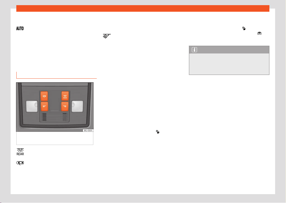
124
Lights
In some cases, e.g. when driving through a tun-
nel without the aut
omatic dipped beam light
function switched on, the instrument clus-
t
er lighting may even switch o. The objective
of this function is to provide the driver with a
visual indication that he or she should activate
the dipped beam. If your vehicle is fitted with
a digital instrument cluster, the message Turn
on the lights will be displayed on the in-
strument cluster.
Interior and reading lights
Fig.106 Det
ail of headliner: front interior
lighting.
Turning the rear interior lights on or o.
Door cont
act connection. The interior
lights come on automatically when you
unlock the vehicle, open a door or discon-
nect the ignition. The light goes out a few
seconds after closing all the doors, when
l
ocking the vehicle or connecting the igni-
tion.
Turning the reading light on and o
The light controls may vary depending on the
vehicle version.
Glove compartment and luggage compart-
ment lighting
When opening and closing the glove compart-
ment on the front passenger side and the rear
lid, the respective light will automatically switch
on and o.
Footwell lighting
The lights in the footwell area below the dash
(driver and front passenger sides) will switch on
when the doors are opened and will decrease
in brightness while driving. This brightness can
be adjusted through the infotainment system
menu using the function button
> Set-
tings > Lighting > Interior light-
ing.
Back
ground lighting
The background lighting lights up the area of
the centre console and the footwell area and,
depending on the version, the front door panels
as well.
The brightness and colour of the background
lighting can be adjusted in the infotainment
menu using the function button
> Set-
tings > Background lighting; OR
>
Background lighting.
Note
The reading lights go out when the vehicle
is cl
osed and locked or after a few minutes
of turning the ignition o. This prevents the
battery from discharging.
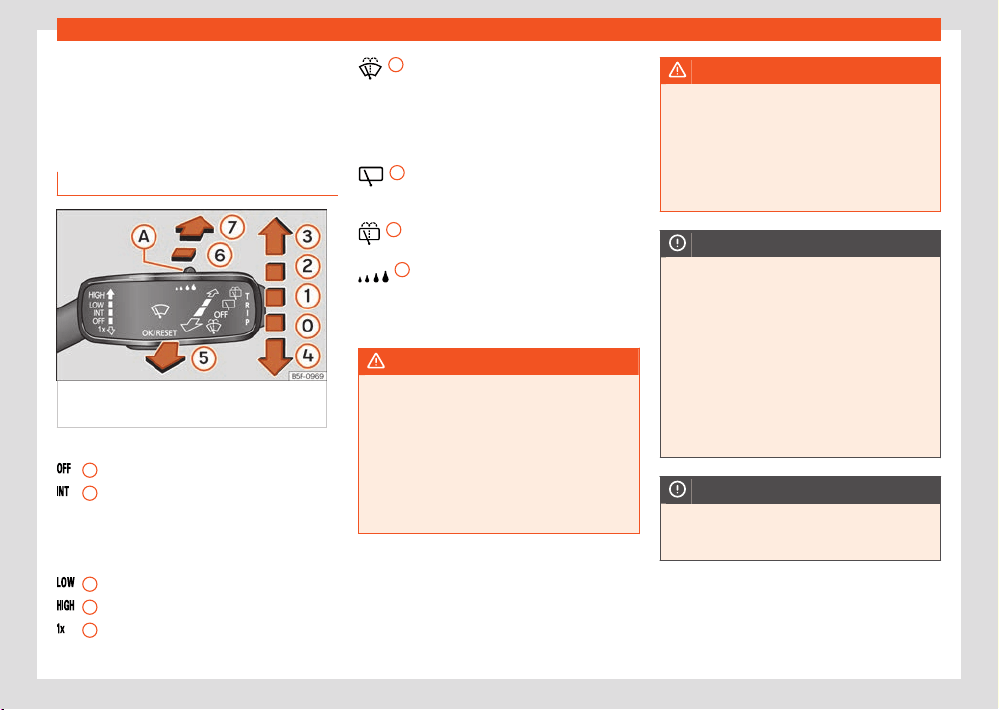
Visibility
125
Windscreen wiper and rear window wiper systems
Visibility
Windscr
een wiper and rear
window wiper systems
Window washer lever
Fig.107 Oper
ating the windscreen wiper and
rear wiper.
More the lever to the required position:
0
Windscreen wipers o.
1
Intermittent wiping of the windscreen
activ
ates the rain sensor. The intermittent
wiping of the windscreen depends on the
speed at which you are driving. The faster
the speed, the more frequent the wiping.
2
Slow wipe.
3
Continuous wipe.
4
Short wipe. Pressing the lever for longer
accel
erates the wiping.
5
Pull the lever to switch on the auto-
matic windscr
een washer/wiper. The Cli-
matronic switches on air recirculation for
approx. 30 seconds to prevent the smell of
windscreen washer fluid from entering the
vehicle interior.
6
Switches on the intermittent rear win-
do
w wipe. The wiper operates at intervals
of approx. 6 seconds.
7
Pressing and holding the lever turns on
the aut
omatic rear window washer/wiper.
A
A Control for adjusting the duration of
the wiping int
ervals (vehicles without rain
and light sensors) or the sensitivity of the
rain sensor.
WARNING
If insucient antifr
eeze is added to the
washer fluid, it could freeze on the glass and
impair visibility.
●
In cold conditions you should not use the
wash/wipe system unless you have warmed
the windscreen with the heating and venti-
lation system. The windscreen washer fluid
could otherwise freeze on the windscreen
and obscure your view of the road.
WARNING
The use of worn or dirty wiper blades re-
duces visibilit
y and increases the risk of seri-
ous accidents and injuries.
●
Replace the wiper blades whenever they
are in poor condition or worn out and
no longer clean the windows suciently
›››page317.
NOTICE
Before driving o and bef
ore switching on the
ignition, check the following aspects of the
wiper blades and the wiper motor to prevent
damage to the glass:
●
The wiper lever is in the neutral position.
●
You have removed or cleared any snow and
ice from the wiper blades and windows.
●
You have carefully removed any wiper
blades that may have frozen from the win-
dow. SEAT recommends a de-icer spray for
this operation.
NOTICE
Do not turn on the wiper until the glass is dry.
Using the wipers whil
e dry can damage the
glass.
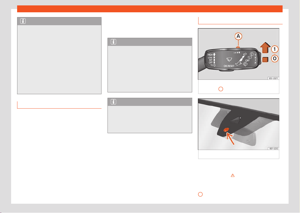
126
Visibility
0
Note
●
When the vehicle stops while the wiper is
on, the wiper s
witches to operating tempora-
rily at the next lower wiping level.
●
If the driver’s or passenger door is opened
when the vehicle is stationary, the wipers re-
turn to the starting position and are switched
o. If the door is closed or the wiper lever is
moved within a few seconds, the wiper turns
on again.
●
In winter, the service position of the wipers
can be useful to make it easier to lift the wip-
ers o the windscreen when the vehicle is
going to be left stationary ›››page317.
Wiper functions
Automatic rear window wipe
The rear wiper switches on automatically when
the wiper is switched on and reverse gear is en-
gaged. The automatic rear window wiper acti-
vation when engaging reverse gear can be ac-
tivated and deactivated in the infotainment sys-
tem, in the vehicle settings menu ›››page37.
Heated windscreen washer nozzles
The heating defrosts any windscreen washer
nozzles that have frozen. The heat output is
automatically adjusted according to the ambi-
ent temperature when the ignition is switched
on. The heater only defrosts the nozzles, but
not the flexible pipes through which the washer
fluid passes.
Note
The windscreen will be wiped again approx-
imat
ely 5 seconds after the windscreen
washer has been activated, provided the ve-
hicle is moving (“drip” function). If you acti-
vate the wipers less than 3 seconds after the
“drip” function, a new wash sequence will
begin without performing the last wipe. For
the “drip” function to work again, you have to
turn the ignition o and then on again.
Note
The wiper will try to wipe away any obsta-
cl
es that are on the windscreen. The wiper
will stop moving if the obstacle is still block-
ing its path. Remove the obstacle and switch
on the wiper again.
Rain and light sensor
Fig.108 Windscr
een wipers lever: adjust the
rain sensor
A
.
Fig.109 R
ain sensor sensitive surface
The rain sensor controls the frequency of the
windscr
een wiper intervals, depending on the
amount of rain ›››
.
Push the l
ever to the desired position
›››Fig.108.
Rain sensor o.
Visibility
127
Mirrors
1
A
Rain sensor on; automatic wipe if neces-
sary.
Setting sensitivit
y level of rain sensor:
– Set control to the right: high sensitivity.
– Set control to the left: low sensitivity.
When the ignition is switched o and then back
on, the rain sensor stays on and starts operat-
ing again when the windscreen wipers are in
position ›››Fig.108
1
and the vehicle is travel-
ling at mor
e than 16km/h (10mph).
Abnormal operation of the rain and light
sensor
The possible causes of anomalies and errone-
ous interpretations in the sensitive surface area
›››Fig.109 of the rain sensor are, among oth-
ers:
●
Damaged wipers: a film of water on the
damaged blades may lengthen the activation
time, reduce the washing intervals or result in a
fast and continuous wipe.
●
Insects: the impact of insects may cause the
wiper to activate.
●
Salt on the road: in winter, salt spread on
the roads may cause an excessively long wipe
when the windscreen is almost dry.
●
Dirt: dry dust, wax, coating on glass (Lotus
eect) or traces of detergent (car wash) may
reduce the eectiveness of the rain sensor or
make it react more slowly, later or not at all.
Regularly clean the sensitive surface of the rain
sensor ›››Fig.109 (arrow) and check for possi-
ble damage to the wiper blades.
●
Windscreen crack: the impact of a stone will
trigger a single wipe cycle with the rain sensor
on. Next the rain sensor detects the reduction in
the sensitive surface area and adapts accord-
ingly. The behaviour of the sensor will vary with
the size of the damage caused by the stone.
WARNING
The rain sensor may not detect enough rain
t
o switch on the wipers.
●
If necessary, switch on the wipers man-
ually when water on the windscreen ob-
structs visibility.
Note
●
To remove wax and coatings, we recom-
mend a windo
w cleaner containing alcohol.
●
Do not put stickers on the windscreen in
front of the rain sensor. This may cause sen-
sor disruption or faults.
Mirrors
General safety instructions
The exterior and interior mirrors allow the driver
to observe vehicles driving behind and adapt
his or her driving behaviour accordingly.
For safe driving, it is important for the driver
to adjust the exterior mirrors and interior mirror
correctly before setting o.
When looking through the exterior mirrors and
the interior mirror, it is not possible to see the
entire area behind and to the sides of the vehi-
cle. These areas outside the field of view are
known as the blind spot. Other road users and
objects may be in the blind spot.
WARNING
Adjusting the exterior mirrors and interior
mirr
or while driving can distract the driver.
This could cause accidents and lead to seri-
ous injuries
●
Only adjust the exterior mirrors and interior
mirror when the vehicle is stationary.
●
When parking, changing lanes, overtaking
or turning, always keep a close eye on your
surroundings, as other road users or objects
may also be in the blind spot.
●
Always make sure that the mirrors are ad-
justed correctly and that visibility to the rear
is not reduced by ice, snow, fogging or other
objects.
128
Visibility
WARNING
A failure to accurately estimate the distance
t
o vehicles driving behind can lead to serious
accidents and injuries.
●
Curved (convex or aspherical) mirrors in-
crease the field of view and objects in them
appear smaller and further away.
●
Curved mirrors do not allow you to pre-
cisely calculate the distance to vehicles
driving behind, so using them when changing
lanes could cause serious accidents and in-
juries.
●
If possible, use the interior mirror to pre-
cisely calculate the distance to vehicles
driving behind you, or to other objects.
●
Always make sure you have sucient visi-
bility to the rear.
WARNING
The automatic anti-dazzle mirrors contain an
el
ectrolyte fluid which could leak if the mirror
is broken.
●
If it gets out, the electrolyte fluid can
irritate the skin, eyes and respiratory or-
gans, particularly in the case of people with
asthma or similar diseases. Immediately in-
hale enough fresh air and get out of the vehi-
cle, or open all windows and doors if this is
not possible.
●
If the electrolytic fluid comes into contact
with your eyes or skin, immediately rinse the
aected area with plenty of water for at
least 15 minutes and seek medical advice.
●
If the fluid comes into contact with foot-
wear or clothing, rinse immediately with
plenty of water for at least 15 minutes.
Clean thoroughly before using the footwear
or clothing in question again.
●
If the electrolytic fluid is swallowed, imme-
diately rinse the mouth with plenty of water
for at least 15 minutes. Do not induce vomit-
ing unless advised by a doctor. Immediately
seek medical attention.
NOTICE
Electrolyte fluid may l
eak if the automatic
anti-dazzle mirror is broken. This liquid at-
tacks plastic surfaces. Therefore, it should
be cleaned as fast as possible with a damp
sponge or similar.
Interior mirror
Rear view mirror with automatic anti-dazzle
function
When the ignition is switched on, the sensors in
the mirror measure the light falling on it from
behind and in front.
The interior mirror automatically darkens based
on the measured values.
If the light falling onto the sensors is blocked or
interrupted, e.g. by a sunshade blind or hanging
objects, the automatic anti-dazzle interior mir-
ror does not work or does not work properly.
Similarly, the use of portable navigation devi-
ces attached to the windscreen or close to the
automatic anti-dazzle interior mirror can aect
the operation of the sensors ›››
.
The aut
omatic anti-dazzle function is deactiva-
ted in certain situations, e.g. when reverse gear
is engaged.
WARNING
Light from screens of portable navigation
de
vices can cause malfunctions of the au-
tomatic anti-dazzle interior mirror and may
cause serious accidents and injuries.
●
Abnormal operation of the automatic anti-
dazzle function may result in it being impos-
sible to use the interior mirror to precisely
calculate the distance to vehicles driving be-
hind, or to other objects.
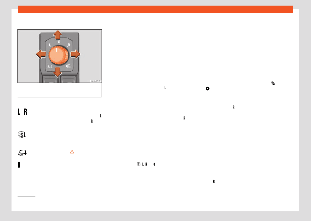
Visibility
129
Mirrors
1)
Regulation in right-hand drive vehicles is symmetrical
/
Adjusting the exterior mirrors
Fig.110 Det
ail of the driver door: control for
the exterior mirror.
Turn the control to the corresponding position.
Moving the control to the desired position
adjusts the mirr
ors on the driver's side (
,
l
eft) and on the passenger's side (
, right)
in the desir
ed direction.
Depending on the equipment fitted on
the vehicle, the mirrors may be heated ac-
cording to the outside temperature.
Folding the mirrors ›››
.
The e
xterior mirror cannot be adjusted and
all functions are deactivated.
Activating exterior mirror functions
The f
ollowing exterior mirror functions can
be activated and deactivated in the vehi-
cle settings menu of the infotainment system
›››page37.
Synchronized regulation of the exterior mir-
rors
The synchronised mirror setting simultaneously
adjusts the right hand exterior mirror when the
left mirror is adjusted
●
Turn the control to position
1)
.
●
Adjust the left-hand exterior mirror. The right
e
xterior mirror will be adjusted at the same time
(synchronised).
●
If necessary, correct the setting of the right
hand mirror: turn the control to position
1)
.
F
old the rearview mirrors when locking the
vehicle
When the vehicle is locked or unlocked from
the outside, the exterior mirrors can be folded in
or out automatically, depending on the equip-
ment. For this purpose, the rotary control has to
be in position
, , , or .
If the r
otary control of the electric exterior mir-
rors is in the folded position, the exterior mirrors
remain folded.
Memory function
The memory butt
ons ›››page114 can be used
to save and turn on settings for the exterior mir-
rors.
The settings will also be saved in the key or in
the user of the online services.
Saving the passenger rear view mirror set-
tings for reversing
●
Switch the ignition on.
●
In the infotainment system, select
>
Settings > Mirrors and wipers >
Mirrors > Lower in reverse gear
›››page37.
●
Select the R
1)
position on the contr
ol.
●
Select reverse gear.
●
Adjust the front passenger exterior mirror so
that you can see
, for example, the kerb area
well.
●
Release the reverse gear.
●
The adjusted position for the rear view mirror
is stored.
Activating the passenger side exterior mirror
settings for reversing
●
Turn the exterior mirror control knob to posi-
tion
1)
.
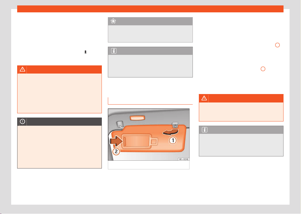
130
Visibility
●
Engage reverse gear with the ignition
s
witched on. The right-hand exterior rear-view
mirror will move to the saved position.
The passenger side exterior mirror leaves the
saved reversing position when the vehicle is
travelling faster than approx. 15km/h (9mph),
or if the control is turned from position
to an-
other position.
WARNING
Fold and unfold the exterior mirror, taking
car
e to avoid injuries.
●
Only fold or unfold the exterior mirror
when there is no-one in the way of the mirror.
●
When moving the mirror, take care not to
trap fingers between the mirror and the mir-
ror bracket.
NOTICE
●
Before washing the vehicle in an automatic
car w
ash, please make sure to fold the ex-
terior mirrors in to prevent them from being
damaged.
●
The electrically folding exterior mirrors
must only be operated electrically, not by
hand, and this could damage their electric
drive.
For the sake of the environment
Do not leave the exterior mirror heating on
f
or longer than necessary. Otherwise it cau-
ses unnecessary energy consumption.
Note
If the electrical adjustment should fail to op-
er
ate, both of the mirrors can be adjusted
by hand by lightly pressing the edge of the
mirror glass.
Sun protection
Sun blind
Fig.111 Sun visor
Options for adjusting driver and front pas-
senger sun visors
●
Lower the sun visor towards the windscreen.
●
The sun visor can be pulled out of its mount-
ing and t
urned towards the door ›››Fig.111
1
.
●
Swing the sun visor towards the door, longitu-
dinally backw
ards.
There is a vanity mirror on the sun visor, with
a cover. When the cover is opened
2
a light
comes on.
The l
amp goes out when the vanity mirror cover
is closed or the sun visor is pushed back up.
WARNING
Folded sun blinds can reduce visibility.
●
Always store sun blinds and visors in their
housing when not in use
.
Note
The light above the sun visor automatically
s
witches o after a few minutes in certain
conditions. This prevents the battery from
discharging.
Air conditioning
131
Heating, ventilation and cooling
Air conditioning
Heating, v
entilation and
cooling
Introduction
Depending on the vehicle’s equipment, several
systems may have been fitted:
●
The manual air conditioning syst
em heats,
cools and dehumidifies the air.
●
The Climatronic is an automatic air condi-
tioner that heats, cools and dehumidifies the
air.
With the Climatronic’s automatic mode it is
possible to automatically regulate the air tem-
perature, distribution and flow.
The air conditioning system is more eective if
the vehicle's interior is kept closed. When a lot
of heat builds up inside the vehicle, ventilation
can speed up the cooling process.
To switch a specific function on, press the ap-
propriate button. Press the button again to
switch o the function.
The illuminated LEDs next to the buttons indi-
cate that the function is switched on.
In the air conditioning settings in the info-
tainment system, the yellow function buttons
indicate that the function is switched on
›››page136.
Economic use of the air conditioning
When the air conditioning is s
witched on, the
compressor consumes engine power and has
influence on fuel consumption.
The air conditioning operates most eectively
with the windows and the sunroof closed. How-
ever, if the passenger compartment has heated
up after standing in the sun for some time, the
air inside can be cooled more quickly by briefly
opening the windows and the sunroof.
Refrigerated glove box
When the vent is open, cold air flows into the
glove box. If the inside of the vehicle is cooled
by the air conditioning system, the cold air can
be directed towards the inside of the glove box.
Air conditioning according to seat occu-
pancy
In order to make the most ecient use possible
of the air conditioning's energy consumption,
the air conditioning is adjusted according to
seat occupancy. When seat occupancy recog-
nition is activated, this is indicated by the word
on the infotainment system and on the air
conditioning contr
ol panel display.
Valid for hybrid vehicles: When a person occu-
pies one of the seats and is wearing a seat
belt, the vehicle identifies this seat as occupied
when the drive system is switched on.
Dust and pollen filter
The dust and pollen filter with its activated
charcoal cartridge serves as a barrier against
impurities in the air taken into the vehicle inte-
rior.
The dust and pollen filter must be changed reg-
ularly so that air conditioner performance is not
adversely aected.
If the filter loses eciency prematurely due to
use in areas with very high levels of air pollu-
tion, the filter must be changed more frequently
than stated in the Service Schedule.
Air vents
To ensure proper heating, cooling and ventila-
tion in the vehicle interior, the air vents must
remain open.
There are other additional, non-adjustable air
vents in the instrument panel, in the footwells
and in the rear area of the passenger compart-
ment.
WARNING
Reduced visibility through the windows in-
cr
eases the risk of serious accidents.
●
Always ensure that all windows are free of
ice and snow, and that they are not fogged,
so as to maintain good visibility of everything
outside.
●
Only drive when you have good visibility.
132
Air conditioning
●
Always ensure that you use the air condi-
tioner and heat
ed rear window to maintain
good visibility.
●
Never leave the air recirculation on for a
long period of time. If the cooling system
is switched o and air recirculation mode
switched on, the windows can mist over very
quickly, considerably limiting visibility.
●
Switch air recirculation mode o when it is
not required.
NOTICE
Food, medicines and other objects sensitive
t
o heat or cold may be damaged or made
unsuitable for use by the air coming from the
vents.
●
Never place food, medicines or other tem-
perature-sensitive objects close to the air
vents.
Note
●
When the cooling system is turned o, air
coming from the outside will not be dried. To
prevent fogging of the windows, SEAT recom-
mends leaving the cooling system (compres-
sor) turned on. To do this, press the function
button . The icon should light up.
●
The maximum heat output required to de-
frost windows as quickly as possible is only
available when the engine has reached its
normal running temperature.
●
Keep the air intake slots in front of the
windscr
een free of snow, ice and leaves to
ensure heating and cooling are not impaired,
and to prevent the windows from misting
over.
●
The air from the vents flo
ws through the ve-
hicle interior and is extracted by slots in the
luggage compartment designed for this pur-
pose. Therefore, you should avoid obstruct-
ing these slots with any kind of object.
●
It is advisable to turn on the air condition-
ing at least once a month, to lubricate the
system gaskets and prevent leaks. If a de-
crease in the cooling capacity is detected,
a Technical Service should be consulted to
check the system.
●
When the engine is under extreme strain,
switch o the compressor for a moment.
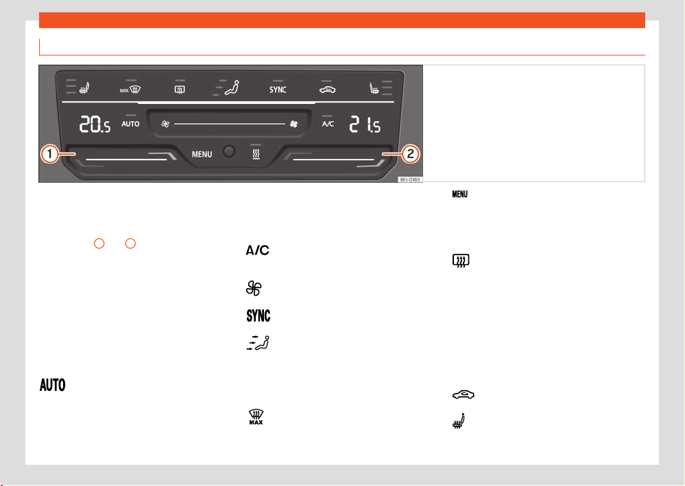
Air conditioning
133
Heating, ventilation and cooling
Climatronic controls and functions
Fig.112 In the centr
e console: Climatronic control
panel.
Some functions and buttons, as well as the air
conditioning f
or the rear seats, are only availa-
ble depending on the vehicle equipment.
Touch zones
1
and
2
The temperature of the right and left sides can
be adjust
ed separately using the adjusters. The
selected temperature is shown on the display of
the climate control panel.
To set the Climatronic temperature to +22 °C
(+72 °F), the centre of the touch control must be
pressed briefly. To adjust the maximum cooling
or heating power, briefly press and hold either
end of the touch control (red or blue zone).
The set air temperature is kept con-
stant. Temperature and the amount and
distribution of air are controlled auto-
matically. Automatic mode is switched o
when the fan power is changed manually.
The fan power in automatic mode can be
selected using the air conditioning profile in
the air conditioning settings of the infotain-
ment system ›››page136.
Switches the cooling system on or o.
The cooling mode cools and dehumidi-
fies the air.
Adjust the fan power.
Synchronizes the driver’s temperature
settings to the passenger side.
Upper arrow: The airflow is directed at
the windscreen.
Central arrow: The airflow is directed to-
wards the chest
Lower arrow: The airflow is directed to-
wards the footwell.
The defrost/demisting function removes
ice and fog from the windscreen. The air
is dehumidified and the fan is set high.
Open the air conditioning settings in the
infotainment system ›››page136.
The climate control operation and settings
menu will be displayed in the infotainment
system screen.
The heated rear window only works when
the engine is running and switches o
automatically after a maximum of 10 mi-
nutes. It should be switched o as soon as
the glass is demisted. By saving electrical
power you can also save fuel.
To avoid possible damage to the battery,
an automatic temporary disconnection of
this function is possible, coming back on
when normal operating conditions are re-
established.
Switches the air recirculation mode on
and o ›››page136.
Switches seat heating on and o
›››page137.

134
Air conditioning
Switches the auxiliary heater on or o
›››page140.
S
witch o the air conditioning system.
Air Conditioning settings in Infotainment
Open the auxiliary heater menu in the air con-
ditioning settings in the infotainment system
›››page136.
Allergen filter
The Air Care Climatronic allergen filt
er can re-
duce the amount of harmful substances that
get inside, including allergens ›››page136.
Windscreen heating
Switches the heated windscreen on and o
with the engine running ›››page139.
St
eering wheel heating
Switches steering wheel heating on and o
›››page138.
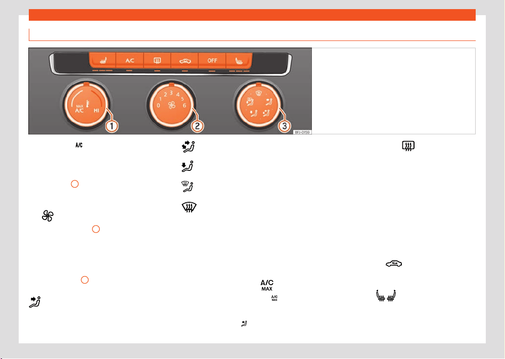
Air conditioning
135
Heating, ventilation and cooling
Manual air conditioning controls
Fig.113 In the centr
e console: manual air
conditioning control panel.
Cooling mode
Press the button to switch on or o the cooling
syst
em.
Temperature
1
Turn the control to adjust the temperature.
F
an
Turning the regulator
2
sets the fan power.
At l
evel 0 the fan and manual air conditioning
are disconnected. Level 6 is the maximum.
Air distribution
Turning regulator
3
distributes the air to the
desir
ed zone:
The airflow is directed towards the chest
The airflo
w is directed towards the chest
and the footwell area.
The airflow is directed towards the foot-
well.
The airflow is directed towards the wind-
screen and the footwell area.
Defrost/demist function. The air flow
is directed towards the windscreen.Air re-
circulation is automatically deactivated
or not activated in the first place. Increase
the fan power to clear the windscreen of
condensation as soon as possible. To de-
humidify the air, the cooling system will au-
tomatically switch on.
Maximum cooling power
When the control is in position air recircu-
l
ation and the cooling system are connected
automatically and the air flow is automatically
adjusted to position
.
Rear window heating
This only works when the engine is running and
s
witches o automatically after a maximum of
10 minutes.
It should be switched o as soon as the glass
is demisted. By saving electrical power you can
also save fuel.
To avoid possible damage to the battery,
an automatic temporary disconnection of this
function is possible, coming back on when nor-
mal operating conditions are re-established.
Air recirculation
›››page136
Seat heating
›››page137
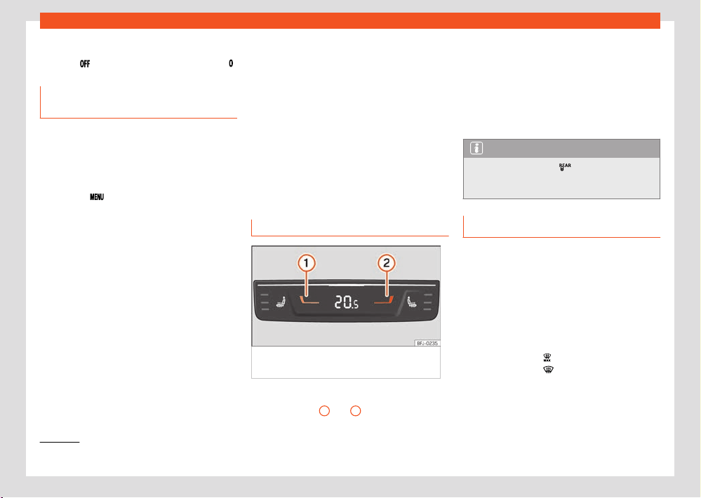
136
Air conditioning
1)
Valid for the front and rear air conditioning control unit.
Switching o
Pr
ess the
button or manually set the fan to .
Setting the t
emperature on the info-
tainment system
The air conditioning settings in the infotainment
system are available in the Climatronic. De-
pending on the vehicle equipment.
Open the air conditioning menu
●
Press the
button on the Climatronic con-
tr
ol panel.
The current air conditioning settings are dis-
played at the top of the screen. The current air
conditioning settings are displayed at the top of
the screen.
Air conditioning operating modes
The air conditioning operating modes are col-
our coded:
●
Blue: Cooling.
●
Red: Heating.
General settings submenu
Sets the following functions:
●
Automatic air recirculation mode
›››page136.
●
Automatic front window heating
›››page139.
Pr
esets submenu
Sets the automatic or manual mode of the
cooling system or switches the air conditioning
o.
Air conditioning profile
Adjust fan power in automatic mode
1)
.
Rear controls
Fig.114 T
o the rear of the centre console:
Climatronic rear seat temperature controls.
Temperature selection
●
Press buttons
1
and
2
›››Fig.1
14 to adjust
the temperature of the rear zone.
Setting the temperature on the infotainment
syst
em
●
Open the air conditioning settings in the info-
tainment system.
●
Press the function button for the rear seat.
●
Press the function buttons to set the tempera-
ture.
Note
When function button is active in the In-
f
otainment System, the rear controls do not
work.
Air recirculation
Air recirculation mode prevents the ambient air
fr
om entering the interior.
When the outside temperature is very high,
selecting manual air recirculation mode for a
short period refreshes the vehicle interior more
quickly.
For safety reasons, air recirculation is switched
o in the following situations:
●
When the button
is pressed or the air dis-
tribut
or is turned to
.
●
When a sensor detects that the vehicle's win-
do
ws could mist up.
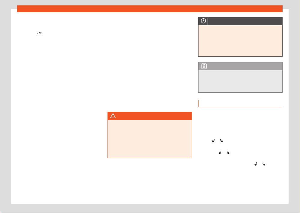
Air conditioning
137
Heating, ventilation and cooling
Switching the manual air recirculation mode
on and o
●
Press the button to switch manual air re-
cir
culation on or o.
Climatronic automatic air recirculation
mode
With the automatic air recirculation mode ac-
tivated, the entry of fresh air into the cabin in-
terior is enabled. If the system detects a high
concentration of hazardous substances in the
ambient air, air recirculation mode is switched
on automatically. When the level of impurities
drops to within a normal range, recirculation
mode is switched o.
The system is unable to detect unpleasant
smells.
The air recirculation will not connect automati-
cally in versions without humidity sensor and in
the following external conditions:
●
The outside temperature is lower than +3°C
(+38°F).
●
The cooling system is switched o and the
outside temperature is below +10°C (+50°F).
●
The cooling system is switched o, the out-
side temperature is below +15°C (+59°F) and
the windscreen wipers are switched on.
Air Care Climatronic with allergen filter
The Air Care Climatronic allergen filter can
reduce the amount of harmful substances, in-
cluding allergens, that get inside.
If the Air Care option is switched on, the air con-
ditioning’s air recirculation mode is maximised
until there is a risk of the windows misting up
due to humidity inside the vehicle and the out-
side temperature. The air recirculation mode is
automatically regulated and incorporates an
automatic setting to prevent the vehicle occu-
pants suering from fatigue.
●
Open the air conditioning settings in the info-
tainment system ›››page136.
●
Switch the Air Care function on or o using
Air Care active
WARNING
Stuy or used air will incr
ease fatigue and
reduce driver concentration possibly result-
ing in a serious accident.
●
Never leave the fresh air fan turned o or
use the air recirculation for long periods of
time; the air in the vehicle interior will not be
refreshed.
NOTICE
In vehicles with an air conditioner, do not
smok
e when air recirculation is switched on.
The smoke may be deposited on the cool-
ing evaporator and on the active combina-
tion filter and cause permanent unpleasant
odours.
Note
When the outside temperature is very high,
briefly s
witching on the air recirculation
mode helps to cool the vehicle interior more
quickly.
Seat heating
With the engine running, the front seats and
side rear seats can be electrically heated to
three power levels.
Control seat heating
●
Press
or on the control panel to turn on
the seat heating at maximum po
wer.
●
Press the
or button repeatedly to adjust it
t
o the required level.
●
To turn o seat heating, press
or several
times until no LEDs ar
e lit.
If the ignition is switched on again in approx.
the next 10 minutes, the driver seat heating is
automatically turned on to the level set the last
time.
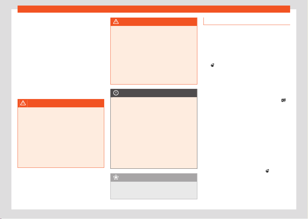
138
Air conditioning
Cases in which the heat seating should not
be s
witched on
Do not switch the seat heating on if any of the
following conditions are met:
●
The seat is occupied by a person with limited
perception of pain or temperature.
●
The seat is not occupied.
●
The seat has a cover.
●
A child seat has been installed on the seat.
●
The seat cushion is wet or damp.
●
The outdoor or indoor temperature is greater
than +25°C (77°F).
WARNING
People who cannot perceive pain or temper-
at
ure because of medications, paralysis or
chronic diseases (e.g. diabetes) or have a
limited perception of these, may suer burns
to the back, buttocks or legs when using seat
heating.
●
People with limited pain and temperature
thresholds must never use seat heating.
●
If an abnormality in the device's tempera-
ture control is detected, have it checked by a
specialist workshop.
WARNING
If the fabric of the cushion is wet, this can
adv
ersely aect the operation of the seat
heating, increasing the risk of burns.
●
Make sure the seat cushion is dry prior to
using the seat heater.
●
Do not sit on the seat with clothing that is
wet or damp.
●
Do not leave clothing that is wet or damp
on the seat.
●
Do not spill liquids on the seat.
NOTICE
●
To avoid damaging the heating elements of
the seat heat
ers, please do not kneel on the
seat or apply sharp pressure to a single point
on the seat cushion or backrest.
●
Liquids, sharps objects and insulating ma-
terials (e.g. covers or child seats) can dam-
age the seat heating.
●
In the event of smells, switch o the seat
heating immediately and have it inspected
by a specialised workshop.
●
If the original seat upholstery is replaced
by another material, the seat heating may
overheat or its operation may be limited.
For the sake of the environment
The seat heating should remain on only when
needed. Otherwise, it is unnecessary energy
consumption.
Steering wheel heating
St
eering wheel heating works only with the en-
gine running.
The selected steering wheel heating level will
be displayed on the instrument panel display.
Adjust the steering wheel heating by press-
ing
on the multifunction steering wheel
●
Short press (less than 1 second):
The heating is s
witched on at its maximum level.
Press the steering wheel button repeatedly to
set the desired level. To switch o steering
wheel heating, press the steering wheel button
repeatedly until the heated steering wheel
icon is displayed on the instrument cluster.
●
Long press (more than 1 second):
The heating is s
witched o directly from the
current operating level. Another long press on
the button switches on the heating directly at
the last level saved before switching o.
Adjust the steering wheel heating via the in-
fotainment system (valid for for hybrid vehi-
cles)
●
In the air conditioning menu, press the steer-
ing wheel heating function button
. The heat-
ing is s
witched on at its maximum level.
●
Press the function button repeatedly to set
the desir
ed level.
●
To switch o steering wheel heating, press the
function button several times until no LED is on.
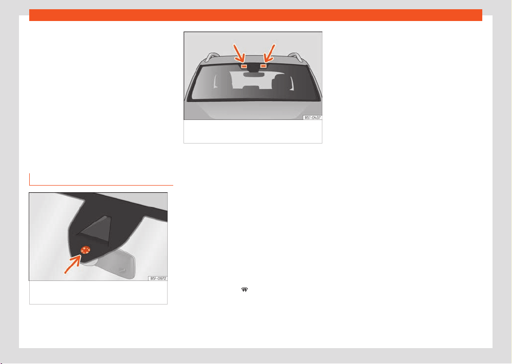
Air conditioning
139
Heating, ventilation and cooling
Automatic disconnection
The st
eering wheel heating will be switched o
automatically when any of the following condi-
tions are met:
●
Electrical energy consumption is too high.
●
The steering wheel heating system is faulty.
●
If the ignition is switched o.
Automatic connection (valid for hybrid vehi-
cles)
When the drive system is re-started within ap-
proximately 10 minutes, the last set heating
level activates automatically.
Windscreen heating
Fig.115 Windscr
een humidity and
temperature sensor.
Fig.116 Ar
eas for placing electronic
accessories
The brake servo works only when the engine is
running.
The heat
ed windscreen is comprised of a set
of heated wires placed between the layers of
the windscreen which, when electric current is
supplied to them, heat up and cause the tem-
perature of the glass to rise.
Its function is to assist the air-conditioning sys-
tem to prevent the windscreen from misting up
or to demist it faster if it does mist up.
The system can be switched on manually or
automatically.
Manual activation
●
Press the button
in the air conditioning
settings in the inf
otainment system.
The heated windscreen is switched o based
on the outside temperature and, in any case,
after approximately 8 minutes.
Automatic activation
The heated windscreen switches on automati-
cally when a window is at risk of misting up.
●
Open the air conditioning settings in the info-
tainment system ›››page136.
●
Switch the automatic heated windscreen on
or o.
The automatic heated windscreen is switched
on, even when the air conditioning is switched
o.
Thermal windscreen using the defrost func-
tion
If the defrost function is switched on and a sen-
sor detects that the windscreen could mist up,
the heated windscreen switches on.
When does the heated windscreen switch
o?
The heated windscreen switches o when one
of the following conditions is met:
●
Power consumption is too high.
●
The air conditioner fuse is faulty.
●
If the preset time has elapsed.
Location of electronic accessories
The windscreen heating has a film that reflects
infra-red rays. This film interferes with the op-
eration of electronic accessories (e.g. remote
tolls or similar devices). To avoid this, there are
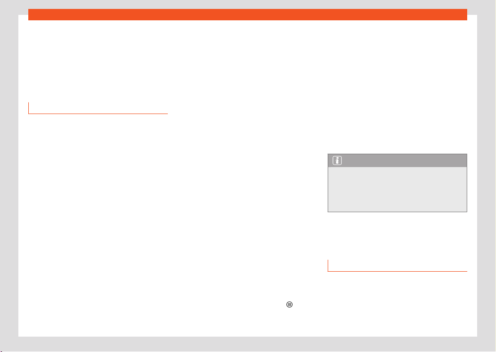
140
Air conditioning
defined ar
eas next to the interior mirror where
these devices can be placed ›››Fig.116 (ar-
rows).
These areas should not be covered and stickers
should not be placed on them, as this could
cause anomalies in the operation of electronic
components placed there.
Troubleshooting
The cooling system cannot be switched on
or its operation is limited
If the air conditioning system cannot be
switched on, this may be caused by the follow-
ing:
●
The engine is not running.
●
The fan is switched o.
●
The air conditioner fuse has blown.
●
The outside temperature is lower than ap-
proximately +3°C (+38°F).
●
The air conditioner compressor has been
temporarily switched o because the engine
coolant temperature is too high.
●
Another fault in the vehicle. Have the air con-
ditioner checked by a specialised workshop.
The heating and fresh air system cannot be
switched on or operates in a limited way
●
The heating and fresh air system and the de-
frost function operate best when the engine is
hot.
●
Hybrid vehicles: Select the Hybrid operating
mode because power in E-MODE is unlimited.
●
If the fault continues, consult a specialised
workshop.
The windows are misted up
Windows mist up when they are cooler than
the ambient temperature and the air is very
damp. Cold air can absorb less moisture than
hot air, so the windows mist up more often in
cold weather.
●
The air vent in front of the windscreen keeps
it free of ice, snow and leaves, which improves
the performance of the heating and cooling
systems.
●
The air grooves located at the rear of the
luggage compartment must be kept clear to
allow the air to circulate through the vehicle
from front to back.
●
Switch on the demist function.
Change the temperature unit (Climatronic)
The temperature display can be changed from
Celsius to Fahrenheit on the Infotainment sys-
tem screen using the function button
> Set-
tings > Units.
Water or water vapour under the vehicle
If the humidit
y and temperature outside the ve-
hicle are high, condensation can drip o the
evaporator in the cooling system and form a
pool underneath the vehicle. This is normal and
does not indicate a leak!
When the outside humidity is high and the am-
bient temperature is low, condensation water
may evaporate when the stationary air condi-
tioning is operating. In this case, steam may
be released from underneath the vehicle. This
does not mean that the vehicle has any dam-
age.
Note
After starting the engine, any residual humid-
it
y in the air conditioner could mist over the
windscreen. Switch on the defrost function
as soon as possible to clear the windscreen
of condensation.
Auxiliary heating and venti-
lation
Introduction
With the auxiliary heating and ventilation, it is
possible to heat the vehicle interior in winter
and ventilate it in summer. It can also be used
to demist the windscreen and remove ice or
even a thin layer of snow. The auxiliary heating
Air conditioning
141
Auxiliary heating and ventilation
is powered by fuel from the vehicle’s tank and
can e
ven continue to operate when the ignition
is switched o. The auxiliary ventilation is pow-
ered by the 12-volt vehicle battery.
The auxiliary heating can be controlled by the
SEAT CONNECT mobile app or through the My-
SEAT website.
The auxiliary heater can be switched on using
the fast heating button of the air conditioning
controls, with the remote control or by previ-
ously programming a departure time in the aux-
iliary heater menu of the infotainment system.
If the outside temperature is very high, the vehi-
cle interior can be ventilated with the engine o
using the auxiliary heater.
Auxiliary heating exhaust system
The exhaust gases generated by the auxiliary
heater are removed via an exhaust pipe fitted
underneath the vehicle. This exhaust pipe must
not be blocked by snow, mud or anything else.
WARNING
The auxiliary heater exhaust fumes contain
carbon mono
xide, an odourless and colour-
less toxic gas. Carbon monoxide can cause
people to lose consciousness. It can also
cause death.
●
Never switch on the auxiliary heater or
leave it running in enclosed spaces or areas
with no ventilation.
●
Never programme the auxiliary heater so
that it switches itself on and is running in an
enclosed space or an area with no ventila-
tion.
WARNING
The components of the auxiliary heater are
e
xtremely hot and could cause a fire.
●
Always park your vehicle so that no part
of the exhaust system can come in contact
with easily flammable materials that might
be below the vehicle, such as dried grass.
NOTICE
Never place food, medicines or other tem-
perature-sensitive objects close to the air
vents. Food, medicines and other objects
sensitive to heat or cold may be damaged
or made unsuitable for use by the air coming
from the vents.
Switching the auxiliary heater and
ventilation on and o
The auxiliary heating can operate with the igni-
tion switched on and o.
Open the Auxiliary heater menu
●
Open the air conditioning settings in the info-
t
ainment system.
●
Press the function button
.
Switching on the auxiliary heater
The auxiliary heating can be s
witched o in the
following ways:
●
Press the immediate heating button
on the
air conditioning contr
ols.
●
OR: Press the button
on the remote control
›››page14
2.
●
OR: Set the departure time ›››page144.
●
OR: Using the App or MySEAT website.
If the 12-volt vehicle battery is low on charge or
the tank is empty, the auxiliary heating cannot
be switched on.
Switch o the auxiliary heating manually
The auxiliary heater can be switched o man-
ually in the following ways:
●
Press the immediate heating button
on the
air conditioning contr
ols.
●
OR: Press the button
on the remote control.
●
OR: Using the SEAT CONNEC
T mobile app or
the MySEAT website.
The auxiliary heater switches o automati-
cally
●
At the scheduled departure time or the end of
the set operating period ›››page144.
●
If the yellow indicator lamp
(fuel gauge)
lights up
.
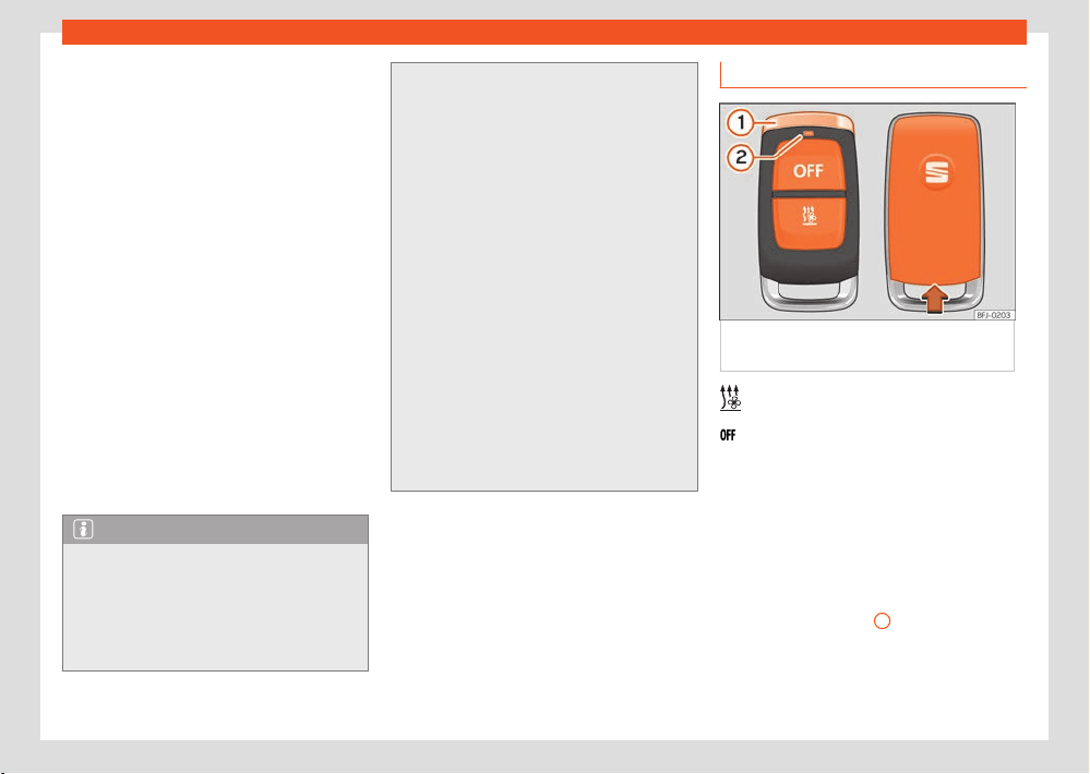
142
Air conditioning
●
If the 12-volt battery's charge level drops
sharply.
●
The auxiliary heating can be turned o imme-
diat
ely with the on/o button.
To burn the remaining fuel in the auxiliary heat-
ing, it continues to operate briefly once it has
been turned o manually or automatically.
Using the auxiliary heating as a supplemen-
tary heater
If the engine has been started, the auxiliary
heating can continue to operate as a supple-
mentary heating system. The following condi-
tion must be met for this to happen:
●
The Automatic supplementary heater
function can be switched on in the infotainment
system's air conditioning settings.
●
The outside temperature is lower than +5 °C
(+41 °F).
The suppl
ementary heating system switches o
again automatically after a while.
Note
●
Noises will be heard while the auxiliary
heat
er is running.
●
When the air humidity is high and the in-
side temperature low, condensation from the
heating and ventilating system may evapo-
rate when the auxiliary heater is switched
on. In this case, steam may be released from
underneath the v
ehicle. This does not mean
that there is a vehicle malfunction.
●
If the vehicle is tilted, e.g. if parked on a
sl
ope, the operation of the auxiliary heater
may be restricted if the fuel tank level is low
(just above the reserve level).
●
If the auxiliary heater is used a number of
times for a long period of time, the 12-volt
battery will lose its charge. To recharge the
battery, the vehicle must be driven for a
number of kilometres from time to time. As
a guideline: the journey should last approxi-
mately as long as the heater was connected.
●
At temperatures below +5°C (+41°F), the
auxiliary heater may switch itself on auto-
matically when the engine is switched on.
The auxiliary heater is switched o again af-
ter a certain time.
●
While the vehicle is stopped, the auxiliary
heating can be switched on up to a maximum
of three consecutive times in a row with the
maximum operating duration.
Remote control
Fig.117 Independent heating: r
adiofrequency
remote control key
Switch on: Pr
ess the button for about one
second
Switch o: Press the button for about one
second
If the buttons of the remote control are pressed
unnecessarily, it could switch on the auxiliary
heater involuntarily, even when it is out of range
or when the control lamp is flashing.
Remote control LED
When the buttons are pressed, the LED of re-
mote control ›››Fig.117
2
gives the user a
r
ange of information:
Air conditioning
143
Auxiliary heating and ventilation
It lights up for approx. 2 seconds
●
In green: The auxiliary heat
er has been
switched on using the
button.
●
In red: The auxiliary heat
er has been switched
o using the
button.
Fl
ashes slowly for approx. 2 seconds
●
In green: No on signal has been received. The
remote control is out of range. Move closer to
the vehicle.
●
In red: No o signal has been received. The
remote control is out of range. Move closer to
the vehicle.
It flashes irregularly
●
In green: The independent heating is blocked.
Possible causes: the fuel tank is almost empty,
the 12-volt battery charge is very low or there is
a fault.
It lights up or flashes steadily
●
In orange (then in green or in red): The remote
control battery is almost flat. However, the on
or o signal has been received.
●
In orange (then flashes green or red): The re-
mote control battery is almost flat. No on or o
signal has been received.
Flashes for around 5 seconds
●
In orange: The remote control battery is flat.
No on or o signal has been received.
Range
The range of the remote control is a few hun-
dred meters when the battery is fully charged
and under optimal conditions.
●
A distance of at least 2 m must be left be-
tween the remote control and the vehicle.
●
There should be no obstacle between the re-
mote control and the vehicle.
●
Secure the remote control with the chrome
pin ›››Fig.117
1
vertically facing upwards.
●
Do not cover the antenna.
The r
ange of the control is considerably less in
poor weather conditions, if there are buildings
in the vicinity or if the battery is low.
Changing the remote control battery
If the indicator lamp does not come on, the re-
mote control's battery must be replaced.
●
Insert a suitable tool, e.g. a screwdriver, into
the indentation in the remote control housing, in
the direction of the arrow ›››Fig.117.
●
With the help of the same tool, lift the lid until
the housing locking element is released.
●
Slightly move the cover in the direction of the
arrow.
●
Remove the cover.
●
To remove the battery, carefully insert a tool
like a screwdriver into the indentation next to
the battery.
●
Use the screwdriver to lift up the battery until
it releases from its housing.
●
Remove the old battery.
●
Insert a new battery of the same type and
make sure it clicks into place. When inserting
the battery, make sure that the polarity is cor-
rect.
●
Fit the cover onto the remote control housing.
●
Slide the cover in the direction opposite to the
arrow until it clicks into place ›››Fig.117.
WARNING
Swallowing a battery with a 20 mm diameter
or any other butt
on battery can cause seri-
ous and even fatal injuries within a very short
time.
●
Always keep the remote control, keyrings
with batteries, the spare batteries, button
batteries and all other batteries over 20 mm
out of reach of children.
●
If you suspect that someone may have
swallowed a battery, seek immediate medi-
cal attention.
144
Air conditioning
NOTICE
●
The radio frequency remote control con-
t
ains electronic components. Therefore,
avoid getting it wet and exposing it to knocks
or direct sunlight.
●
The use of inappropriate batteries may
damage the radio frequency remote control.
For this reason, always replace the used bat-
tery with another of the same voltage, size
and specifications.
For the sake of the environment
●
Please dispose of your used batteries cor-
r
ectly and with respect for the environment.
●
The remote control battery may contain
perchlorate. Observe the legal provisions re-
garding disposal.
●
Care should be taken so as not to operate
the remote control unintentionally so as to
prevent the auxiliary heater being switched
on accidentally.
Programming the auxiliary heater
Before programming it, check that the vehicle's
date and time are set correctly›››
.
The auxiliary heat
er is programmed in the Aux-
iliary heater menu of the infotainment sys-
tem.
Set the operating duration of the auxiliary
heating
●
Open the Auxiliary heater menu.
●
Press the Set function butt
on.
●
To set the operating time, press the Operat-
ing duration butt
on.
The set operating duration is taken into account
when the auxiliary heating is switched on using
the immediate heat button
or the remote
contr
ol.
The maximum duration of the auxiliary heating
is 60 minutes.
Set the departure time
Activating this function only aects the heating
or ventilation. The departure time must be reac-
tivated whenever the vehicle is started.
●
Open the Auxiliary heater menu.
●
Press the Set function butt
on.
●
Select one of the memory spaces for a De-
parture time.
●
Press the Activate function butt
on.
Manual air conditioning: The scheduled depar-
ture time determines when the auxiliary heating
or ventilation will be switched o. The start of
the heating or ventilation process depends on
the programmed duration of operation.
Climatronic: The vehicle uses the programmed
departure time to automatically calculate the
time at which the heating or ventilation process
should begin to attain the set temperature.
A departure time can be scheduled in the App
or on the MySEAT website.
Checking the programming
If a departure time is activated, the yellow LED
on the immediate heat button
lights up on
the Climatr
onic control panel, approximately
ten seconds after the ignition is switched o.
WARNING
Never programme the auxiliary heater so
that it s
witches itself on and is running in
an enclosed space or an area with no ven-
tilation. The auxiliary heater exhaust fumes
contain carbon monoxide, an odourless and
colourless toxic gas. Carbon monoxide can
cause people to lose consciousness. It can
also cause death.
Driving
145
Driving indications
Driving
Driving indications
P
edals
●
Ensure that you can always press the accel-
er
ator, brake and clutch pedals unimpaired to
the floor.
●
Ensure that the pedals can return unimpaired
to their initial positions.
●
Ensure that the floor mats are securely fas-
tened during the trip and do not obstruct the
pedals ›››
.
Only use floor mats which l
eave the pedals
clear and which are secured to prevent them
from slipping. You can obtain suitable floor mats
from a specialised dealership. Fasteners for
floor mats are fitted in the footwells.
Wear suitable footwear
Always wear shoes which support your feet
properly and give you a good feeling for the
pedals.
WARNING
●
Restricting pedal operation can lead to
critical sit
uations while driving.
●
Never lay or fit floor mats or other floor
coverings over the original floor mats. This
would reduce the pedal area and could ob-
struct the pedals. Risk of accident.
●
Never place objects in the driver footwell.
An object could move into the pedal area
and impair pedal operation.
Selecting the optimal gear
Depending on the equipment on the instrument
panel screen, a recommendation is shown with
the gear that should be engaged to optimise
consumption.
On vehicles with automatic transmission, it is
only displayed when driving in Tiptronic mode
›››page163.
No recommendation will appear if the optimal
gear is engaged. The current gear will be dis-
played.
Display Meaning
3
Optimum gear.
4
5 Changing to a higher gear is rec-
ommended.
2 1 Changing to a lower gear is rec-
ommended.
Information regarding the “cleanliness” of
the par
ticulate filter
When the exhaust system detects that the par-
ticulate filter is close to saturation, this system’s
self-cleaning function recommends the optimal
gear for that function ›››page314.
WARNING
The gear change recommendation is an aux-
iliary function and in no case shoul
d be a
substitute for careful driving.
●
Responsibility for selecting the correct
gear, depending on the circumstances, rests
solely with the driver.
For the sake of the environment
Selecting the correct gear can help to save
fuel.
Note
The recommended gear display turns o
when you are no longer in tiptronic mode.
Economical and environmentally
friendly driving
Fuel consumption, environmental pollution and
wear to the engine, brakes and tyres all depend
largely on driving style. Consumption can be
reduced between 10-15% with an ecient driv-
ing type. The following section gives you some

146
Driving
tips on lessening the impact on the environment
and r
educing your operating costs at the same
time.
Active cylinder management (ACT®)
Depending on vehicle equipment, the active
cylinder management (ACT®) may deactivate
some of the engine cylinders if the driving sit-
uation does not require too much power. The
number of active cylinders can be seen on the
instrument panel display ›››page16.
Foresight when driving
If you think ahead when driving, you will need
to brake less and thus accelerate less. Take ad-
vantage of the inertia of the vehicle whenever
possible, with a gear engaged. This takes ad-
vantage of the engine braking eect, reducing
wear on the brakes and tyres. Emissions and
fuel consumption will drop to zero.
Changing gear to save energy
An eective way of saving is to change in ad-
vance to a higher gear.
Manual gearbox: change from first to second
gear as soon as possible. Choosing the cor-
rect gear saves fuel. Select the highest possi-
ble gear suitable for the driving situation (the
engine should continue to run with cyclical reg-
ularity).
Automatic transmission: accelerate gradually
and without reaching the “kick-down” position.
Avoid driving at high speed
Avoid travelling at your vehicle’s top speed,
whenever possible. Fuel consumption, emission
of harmful gases and noise pollution multiply as
speed is increased. Driving at moderate speeds
will help to save fuel.
Reduce idling time
In vehicles with the Start-Stop system idling is
automatically reduced. In vehicles without the
Start-Stop system it is worth switching o the
engine, for example, at level crossings and at
trac lights that remain red for long periods of
time. When an engine has reached operating
temperature, and depending on the cylinder
capacity, keeping it switched o for a minimum
of about 5 seconds already saves more than
the amount of fuel necessary for restarting.
The engine takes a long time to warm up when
it is idling. Mechanical wear and pollutant emis-
sions are also especially high during this initial
warm-up phase. It is therefore best to drive
o immediately after starting the engine. Avoid
running the engine at high speed.
Regular maintenance
Regular servicing helps in saving fuel even be-
fore the engine is started. A well-serviced en-
gine gives you the benefit of improved fuel
eciency as well as maximum reliability and
an enhanced resale value. A badly serviced en-
gine can consume up to 10% more fuel than
necessary.
Avoid short journeys
The engine and catalytic converter need to
reach their optimal operating temperature in
order to minimise fuel consumption and emis-
sions.
A cold engine consumes a disproportionate
amount of fuel. The engine reaches its work-
ing temperature after about four kilometres (2.5
miles), when fuel consumption will return to a
normal level.
Check tyre pressure
Always make sure the tyres are inflated to the
correct pressures ›››page349 to save fuel. If
the pressure is below half bar, fuel consumption
may increase by 5%. Due to the greater rolling
resistance, under-inflation also increases tyre
wear and impairs handling.
Do not use winter tyres all year round as they
increase fuel consumption by up to 10%.
Avoid carrying unnecessary loads
Given that every kilo of extra weight will in-
crease the fuel consumption, it is advisable
make sure that no unnecessary loads are being
transported.
Since the luggage rack increases the aerody-
namic drag of the vehicle, you should remove
it when not needed. At speeds of 100-120km/h
(62-75mph), this will save 12% of fuel.
Driving
147
Driving indications
Save electrical energy
The engine driv
es the alternator, thereby gen-
erating electricity. This implies that any in-
crease in power consumption also increases
fuel consumption! For this reason, switch o any
unneeded electrical devices. Devices that use
a lot of electricity include the blower at a high
setting, the rear window heating or the seat
heating.
Plug-in hybrid drive: brake early and evenly to
take advantage of energy recovery.
Note
●
If you have the Start-Stop system, it is rec-
ommended that it shoul
d not be disconnec-
ted.
●
It is recommended that you close the win-
dows when driving at more than 60km/h
(37mph).
●
Do not drive with your foot resting on the
clutch pedal, as the pressure can make the
plate slip. This causes wear and can damage
the clutch plate.
●
Do not ride the clutch on a hill, use the
brake. The fuel consumption will be lower
and you will prevent the clutch plate from
being damaged.
●
Use the engine brake on downhills by
changing to the gear that is best suited for
the gradient. Fuel consumption will be “zero”
and the brakes will not suer.
Driving with a loaded vehicle
In or
der to achieve appropriate driving charac-
teristics when the vehicle is loaded, please note
the following:
●
Place all luggage securely ›››page286.
●
Accelerate with particular care and precau-
tion.
●
Avoid sudden braking and manoeuvres.
●
Brake earlier than usual.
●
If applicable, please note the information
about the r
oof rack ›››page295.
WARNING
Loads that move around could seriously
thr
eaten the vehicle's stability and safety,
extend the braking distance during hard or
emergency braking and lead to serious acci-
dents and injuries.
●
Secure the load correctly to prevent it from
moving around.
●
Secure heavy objects with suitable lashing
straps or tie-down belts.
●
Ensure that the rear seat backrests are se-
curely engaged.
Driving with the rear lid open
Driving with the r
ear lid open is particularly
dangerous. Secure all objects and the open
rear lid correctly and take any necessary
measures.
Driving with the rear lid open increases the aer-
odynamic drag of the vehicle, along with fuel
consumption. It is therefore recommended that
you do not drive with the rear lid open.
WARNING
Driving with the rear lid unlocked or open can
cause serious injury.
●
Always drive with the rear lid closed.
●
Place all objects securely inside the lug-
gage compar
tment. Otherwise, loose ob-
jects could fall out of the luggage compart-
ment and injure road users driving behind.
●
Always drive carefully and with special
care and anticipation.
●
Avoid braking and sudden manoeuvres, as
the open rear lid could move uncontrollably.
●
When transporting objects that protrude
from the luggage compartment, mark them
accordingly to warn other road users. Please
bear in mind all legal provisions.
●
Never use the rear lid to support or secure
objects protruding from the luggage com-
partment.
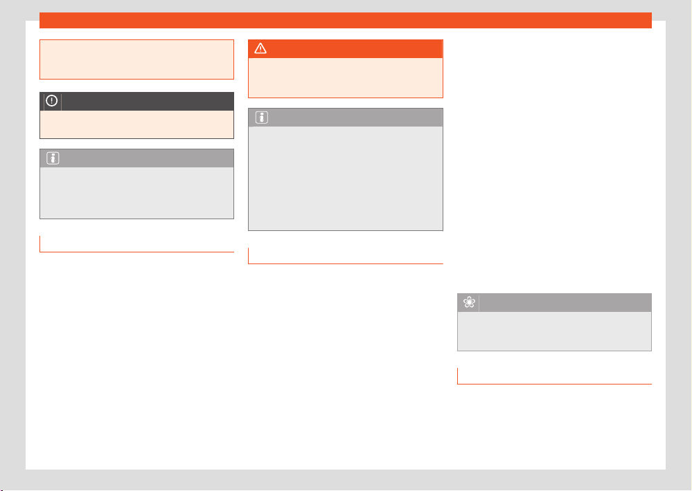
148
Driving
●
If a luggage rack is fitt
ed on the rear lid, re-
move it and the load when you have to drive
with the rear lid open.
NOTICE
An open rear lid changes the height and, in
some cases, the l
ength of the vehicle.
Note
Depending on the country, it may be forbid-
den t
o drive with the rear lid open. Please
observe the legal regulations of the country
in question.
Driving on flooded roads
To prevent damage to the vehicle driving on
flooded roads, take the following into account:
●
Water should ne
ver come above the lower
edge of the bodywork.
●
Drive at pedestrian speed.
●
Never stop the vehicle in the water, drive in
reverse or stop the engine.
●
Vehicles driving in the opposite direction form
waves that can raise the water level so high
that your vehicle will not be able to cross the
water safely.
WARNING
After driving through flooded z
ones, braking
eectiveness can decrease if the brake discs
or pads are damp ›››page172.
Note
●
Driving through flooded ar
eas may se-
verely damage vehicle components such as
the engine, drive train or electrical system.
●
Avoid driving through salt water (corrosion)
›››page367.
●
Whenever driving through water, the
Start-Stop system must be switched o
›››page158.
Running in
Please observe the instructions for running-in
new components.
Running-in the engine
A new engine must be driven through a
run-in period during its first 1500 kilometres
(1000 miles). During its first few hours of run-
ning, the internal friction in the engine is greater
than later on when all the moving parts have
bedded down.
How the vehicle is driven for the first 1500km
(1000 miles) influences the future engine per-
formance. Throughout the life of the vehicle,
it should be driven at a moderate speed (es-
pecially when the engine is cold) this will re-
duce engine w
ear and increase its useful life.
Never drive at extremely low engine speeds.
Always engage a lower gear when the engine
works “irregularly”. For the first 1000km or
600 miles, please note:
●
Do not use full throttle.
●
Do not force the engine above two thirds of its
maximum speed.
●
Do not tow a trailer.
Between 1000 and 1500 kilometres (600 to
1000 miles), gradually increase power until
reaching the maximum speed and high engine
speeds.
Running in new tyres and brake pads
●
Replacement of wheel rims and new tyres
›››page348.
●
Information about brakes ›››page172.
For the sake of the environment
If the engine is run in gently, the life of the
engine will be incr
eased and the engine oil
consumption reduced.
Four-wheel drive (4Drive)
On four-wheel drive models, the engine power
is distributed to all four wheels
Driving
149
Driving indications
General notes
On f
our-wheel drive vehicles, the engine power
is distributed to all four wheels. The distribution
of power is controlled automatically according
to your driving style and the road conditions.
See also ›››page174.
The four-wheel drive is specially designed to
complement the superior engine power. This
combination gives the vehicle exceptional han-
dling and performance capabilities, both on
normal roads and in more dicult conditions,
such as snow and ice. Even so (or perhaps es-
pecially for this reason), it is important to ob-
serve certain safety points ›››
.
Wint
er tyres
Thanks to four-wheel drive, your vehicle will
have plenty of traction in winter conditions,
even with the standard tyres. Nevertheless, we
still recommend that winter tyres or all-season
tyres be fitted on all four wheels to give even
better braking response.
Snow chains
On roads where snow chains are mandatory,
this also applies to cars with four-wheel drive
›››page352.
Changing tyres
On vehicles with four-wheel drive, all four tyres
must have the same rolling circumference. Also
avoid using tyres with varying tread depths
›››page348.
O-roader?
Your SEAT vehicle is not an o-roader: in fact,
the ground clearance is not enough to be used
as such. Avoid consequently rough tracks and
uneven terrain.
WARNING
●
Even with four-wheel drive, you should al-
w
ays adjust your speed to suit the condi-
tions. Do not let the extra safety features
tempt you into taking any risks when driving.
Accident hazard!
●
The braking capability of your vehicle is
limited by the tyres' grip. It is therefore no dif-
ferent from a car without four-wheel drive. So
do not be tempted to drive too fast on firm or
slippery roads just because the vehicle still
has good acceleration in these conditions.
Accident hazard!
●
On wet roads bear in mind that the front
wheels may start to “aquaplane” and lose
contact with the road if the car is driven too
fast. If this should happen, there will be no
sudden increase in engine speed to warn the
driver, as occurs with a front-wheel drive car.
For this reason you should always choose
a driving speed suitable for the road condi-
tions. Accident hazard!
Trips abroad
The vehicle has been manufactured for a spe-
cific country and meets the approval regula-
tions in force in that country at the time it was
manufactured.
If you are going to use the vehicle abroad tem-
porarily or for a short period of time, please
observe the relevant instructions.
Some countries have special safety regulations
and provisions that the vehicle may not com-
ply with. Before travelling abroad, SEAT recom-
mends that you seek information from one of
your dealers about the legal provisions in force
in your destination country.
If you are going to sell the vehicle in another
country or use it there for a longer period of
time, please observe the legal regulations in
force in the country in question.
In some cases it may be necessary to install or
remove certain equipment at a later date, and
to deactivate certain functions. Sets and types
of services may also be aected. In particular,
this can occur if the vehicle is to be used in an-
other climatic region for a long period of time.
Due to the dierent frequency bands around
the world, the factory-fitted infotainment sys-
tem may not work in another country.
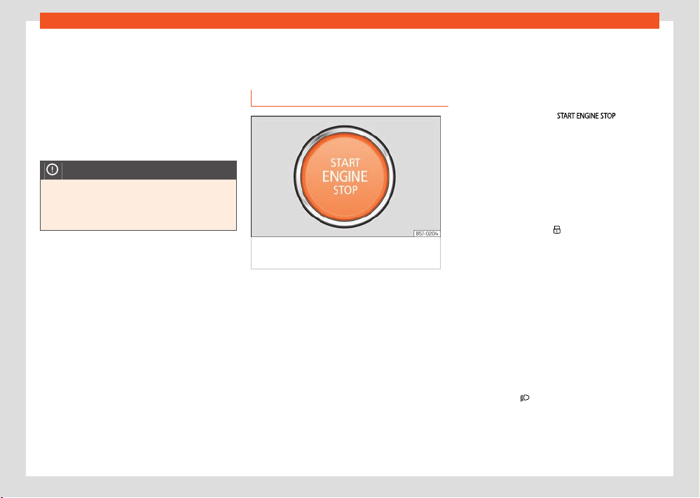
150
Driving
With petrol vehicles, it should be ensured that
l
ead-free petrol is available throughout the
journey. Seek information about service station
networks selling unleaded fuel.
SEAT importers and distributors will provide in-
formation about the technical preparation that
your vehicle requires and also about necessary
maintenance and repair possibilities.
NOTICE
SEAT does not accept liability for any dam-
age t
o the vehicle due to the use of a lower
quality fuel, an inadequate service or the
non-availability of genuine spare parts.
Starting and stopping the
engine
Switching the ignition on/o
Fig.118 In the l
ower part of the centre console:
start button.
The engine can be started with a start button
(Pr
ess & Drive). To do so, there must be a valid
key inside the vehicle in the area of the front or
rear seats, or on the centre console.
In vehicles with the Keyless Access system, the
engine can also be started with the key in the
luggage compartment.
Opening the driver's door when exiting the ve-
hicle activates the electronic lock on the steer-
ing column if the ignition is disabled.
Switching the ignition on/o
If you only w
ant to switch on the ignition (with-
out starting the engine), briefly press the start
button once without pressing the brake pedal
or the clutch pedal ›››page151.
The starter button text
flashes
lik
e a heartbeat when the system is preset for
switching the ignition on and o.
Automatic ignition disconnection
If the driver leaves the vehicle, taking the key
with them but leaving the ignition on, the igni-
tion does not switch o automatically. The igni-
tion is switched o by pressing the lock button
on the remote control
or by pressing the sen-
sor surf
ace on the door lever. ›››page84
Automatic deactivation of the ignition on ve-
hicles with the Start-Stop system
The ignition is switched o automatically when
the vehicle is stopped and the automatic en-
gine shutdown is active, if:
●
The driver's seat belt is not fastened,
●
the driver does not step on any pedal,
●
the driver door is opened.
After automatically turning o the ignition, if the
dipped beam
is on, the side light remains
on f
or approx. 30 minutes (if the battery has
enough charge). If the driver locks the vehicle
or manually turns o the light, the side light
goes out.
Driving
151
Starting and stopping the engine
Switching o the ignition when l
eaving the
vehicle, with hybrid drive
When the ignition is not switched o in E-MODE
operating mode, a certain amount of time af-
ter the journey is complete it switches o auto-
matically to prevent draining the 12-volt vehicle
battery.
Engine restart feature
If no key is detected inside the vehicle after the
engine stops, you will only have 5 seconds to
restart it. A warning will display on the dash
panel screen.
After this interval, it will not be possible to start
the engine without a valid key inside the vehicle.
Function “My Beat”
For vehicles with a convenience key there is the
“My Beat” function. This feature provides an ad-
ditional indication of the vehicle ignition system.
When entering the vehicle, the start button
›››Fig.118 flashes to draw attention to it.
When the ignition is on/o, the engine start but-
ton flashes.
With the ignition is switched o, the start button
goes o after a few seconds.
With the engine running, the start button light
stays on, indicating that the engine is running.
The time elapsed between the moment the
user starts the engine with the start button and
the lighting changes from flashing to fixed will
depend on specific engine size characteristics.
When the start button is used to stop the en-
gine, the button starts flashing again.
In vehicles with the Start-Stop system, the
“My Beat” function also oers additional infor-
mation:
●
When the engine stops during the Stop
phase, the light of the start button stays on,
as the Start-Stop system remains active even
though the engine is o.
●
When the engine cannot be started again
with the Start-Stop system ›››page158 and
needs to be started manually, the start button
flashes to indicate this situation.
WARNING
When switching on the ignition, do not press
the br
ake or clutch pedal, otherwise the en-
gine could start immediately.
WARNING
If vehicle keys are used negligently or with-
out due car
e, this may cause accidents and
serious injury.
●
Never leave any key inside the vehicle
when you leave it. Otherwise, a child or un-
authorised person could lock the vehicle,
start the engine or connect the ignition and
operate any of the electrical equipment.
Note
●
Before leaving the vehicle, always discon-
nect the ignition and, if appr
opriate, take into
account the instructions on the screen of the
dash panel.
●
If the vehicle is stationary for a long time
with the engine o and the ignition on, the
v
ehicle battery might be discharged and it
might not be possible to start the engine.
●
In vehicles with diesel engines, wait until
the warning light
goes o bef
ore starting
the engine.
●
If during the STOP phase you press the
button, the ignition is switched
o and the push-butt
on flashes.
●
If the following indication appears on the
instrument cluster display: “Start-Stop
system deactivated: Start the en-
gine manually”; the button
will flash.
St
arting the engine
●
Vehicles with manual transmission: put the
gear l
ever in neutral, press the clutch pedal and
keep it pressed in this position until the engine
starts.
●
Vehicles with automatic transmission: put the
selector lever in P or N, press the brake pedal
and keep it pressed in this position until the en-
gine starts.
152
Driving
●
Press the start button without pressing the
accel
erator. There must be a valid key in the
vehicle for the engine to start. After starting the
engine, the lighting of the
button
r
emains fixed indicating that the engine is run-
ning.
●
Once the engine starts, release the start but-
ton.
●
If the engine does not start, stop and wait
for around 1 minute to try again. If necessary,
perform an emergency start ›››page154.
Diesel engines can take a few seconds longer
than usual to start on cold days. During pre-
heating, the warning lamp
remains lit. To
av
oid unnecessary discharging of the battery,
do not use any other major electrical equip-
ment while the glow plugs are pre-heating.
The preheating time depends on the coolant
and exterior temperatures. With the engine at
operating temperature, or at outside tempera-
tures above +8°C, the warning lamp
will light
up f
or about one second. This means that you
can start the engine almost immediately.
Starting a diesel engine after having run out
of fuel
If the fuel tank of a diesel vehicle was run until
completely empty, after refuelling it can last
longer than normal to start the engine, even
up to a minute. This is because the fuel system
must eliminate air first.
WARNING
Do not keep the engine running in confined
spaces, as ther
e is a risk of poisoning.
●
The exhaust gases contain carbon monox-
ide, an odourless and colourless poisonous
gas that can cause loss of consciousness
and death.
WARNING
Do not get out of the vehicle with the en-
gine running, especially if a gear is engaged.
The v
ehicle could then suddenly move or
something strange could happen that would
cause damage, fire or serious injury.
WARNING
Never use cold start sprays, they could ex-
plode or cause the engine to run at high revs.
Doing this risks injury.
NOTICE
●
The starter motor or the engine may be
damaged if you try t
o restart the engine im-
mediately after switching it o.
●
When the engine is cold, you should avoid
high engine speeds, driving at full throttle
and over-loading the engine, as this could
cause engine damage.
For the sake of the environment
Do not warm-up the engine by running the
engine with the v
ehicle stationary. Start o
immediately, driving gently. This helps the
engine reach operating temperature faster
and reduces emissions.
Note
Electrical components with a high power
consumption ar
e switched o temporarily
when the engine starts.
●
When starting with a cold engine, noise
levels may briefly increase. This is quite nor-
mal, and no cause for concern.
●
When the outside temperature is below
+5°C (+41°F), if the engine is diesel, some
smoke may appear under the vehicle when
the fuel-operated auxiliary heater is on.
Turning o the engine
●
Bring the vehicle to a full stop ›››
.
●
Vehicles with manual transmission: fully de-
pr
ess the clutch.
●
Vehicles with automatic transmission: Move
the selector lever to the P position.
●
Apply the electronic parking brake.
●
Briefly press the start button.
Driving
153
Starting and stopping the engine
Emergency disconnection
If the engine does not s
witch o after briefly
pressing the starter button, an emergency dis-
connect will be required:
●
Press the start button twice within 3 seconds
or press it once for more than 1 second.
Car wash function (hybrid vehicles)
When the ignition is turned o with gear N ac-
tivated, the vehicle can roll for the next 30 mi-
nutes. After that time, if the vehicle is stopped
the parking lock P activates automatically. The
corresponding warning message is displayed
on the instrument cluster display one minute
before this happens.
WARNING
Never switch o the engine whil
e the vehicle
is moving. This could cause loss of control of
the vehicle, accidents and serious injury.
●
The airbags and belt tensioners do not
work when the ignition is switched o.
●
The brake servo does not work with the
engine o. Therefore, you need to press the
break pedal harder to brake the vehicle.
●
Power steering does not work when the en-
gine is not running. You need more strength
to steer when the engine is switched o.
●
If the ignition is switched o, the steering
column could be locked, making it impossi-
ble to control the vehicle.
WARNING
Always take the key with you when you leave
the v
ehicle. This is particularly important if
there are children in the vehicle, as they
might otherwise be able to start the engine
or use power-operated equipment (e.g. the
electric windows), which could cause inju-
ries.
NOTICE
●
If the vehicle is stopped and the Start-Stop
syst
em switches o the engine, the ignition
remains switched on. Make sure that the ig-
nition is switched o before leaving the vehi-
cle, otherwise the battery could discharge.
●
If the engine has been driven at high speed
for a prolonged period of time, it may over-
heat when switched o. To avoid damage,
allow the engine to run for approximately two
minutes in neutral before switching it o.
Note
After the engine is switched o the radiator
fan may run on for up to 10 minutes, even
if the ignition is switched o. It is also pos-
sible that the fan turns itself on once more
if the coolant temperature increases due to
the heat accumulated in the engine com-
partment or due to its prolonged exposure to
solar radiation.
Electronic immobilizer
The el
ectronic immobiliser helps to prevent the
engine from being started with an unauthorised
key and, consequently, the vehicle being put in
motion.
The vehicle key has an integrated chip which
automatically deactivates the electronic immo-
biliser if there is a valid key inside the passenger
compartment.
The electronic immobiliser is automatically ac-
tivated when there is no longer a valid key in-
side the vehicle.
For this reason, the engine can only be started
with a properly coded Original SEAT key. This
type of keys can be purchased from a SEAT
dealer.
NOTICE
A perfect operation of the vehicle is ensured
if genuine SEAT k
eys are used.
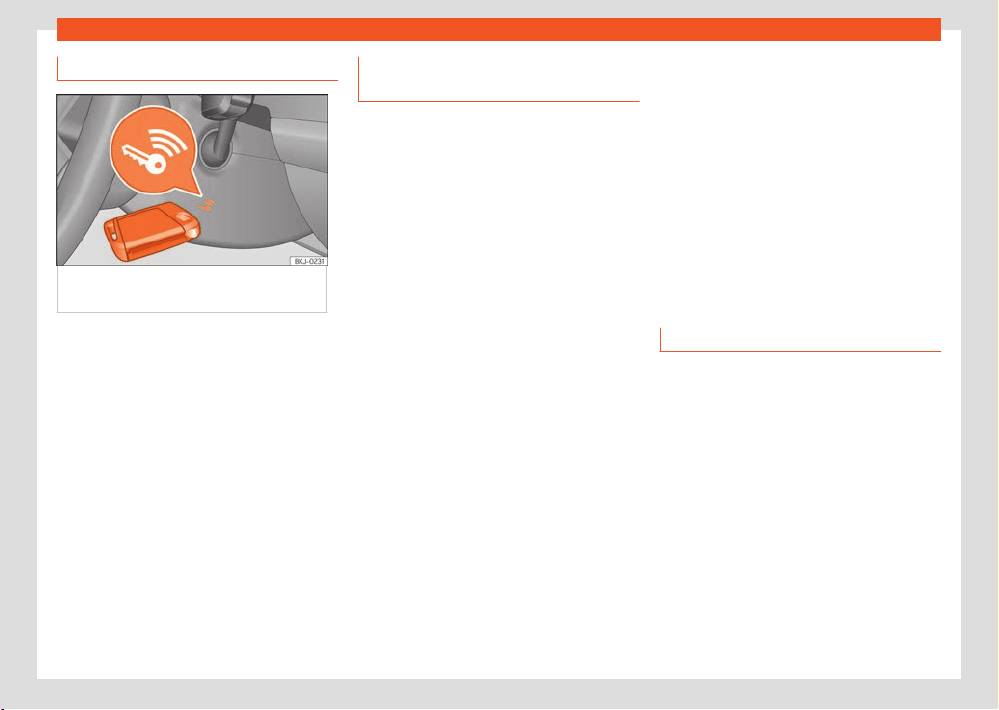
154
Driving
Emergency starting function
Fig.119 On the right of the st
eering column:
emergency start.
If no valid key is detected inside the vehicle,
an emer
gency start-up will be required. The rel-
evant message will appear in the dash panel
display. This may happen when, for example,
the vehicle key battery is very low.
●
Immediately after pushing the starter button,
keep the key next to the right trim of the steer-
ing column ›››Fig.119, as close as possible to
the Kessy logo.
●
The ignition connects and the engine starts
automatically.
Indications for the driver on the in-
strument clust
er screen
Depress the clutch
●
This indication is displayed on vehicles with
a manual gearbox when the driver does not
depress the clutch pedal when starting the en-
gine. The engine can only be started if the
clutch pedal is depressed.
Press the brake
●
This message appears on vehicles with an
automatic gearbox if the driver tries to start the
engine without having the brake pedal pressed.
Select N or P
●
This message appears if you try to start or
stop the engine when the selector lever of the
automatic gearbox is not in position P or N.
The engine can only be started and stopped
in those positions.
Engage position P; the vehicle can
move; doors can only be locked in
position P.
●
For safety reasons, this driver message ap-
pears and an audible warning sounds if the se-
lector lever of the automatic gearbox is not in
position P after you switch o the ignition. Move
the selector lever to the P position, otherwise
the vehicle could move.
Gear change: Selector lever in the
drive position!
●
This driver message is displayed when the
sel
ector lever is not in the position P when the
driver door is opened. Additionally, a buzzing
sound is emitted. Put the selector lever in posi-
tion P, otherwise the vehicle could roll away.
Ignition is switched on
●
This driver message is displayed and a buz-
zer is sounded when the driver door is opened
with the ignition switched on.
Driving with electric drive
Switching on the hybrid drive system
✓ Valid for: hybrid vehicles
Switching on the hybrid drive activates the ve-
hicle's propulsion system. When the vehicle’s
drive system is switched on, the electric drive
is activated. The combustion engine starts au-
tomatically when the charge level of the high-
voltage battery is not sucient to run with the
electric drive, or if high drive power is required.
Requirements for switching on the drive sys-
tem
The drive system can be switched on when the
following conditions are met:
Driving
155
Driving with electric drive
●
The high voltage battery has a sucient
char
ge level.
●
There is no charging cable plugged in.
●
The temperature of the high-voltage battery
is within the operating range.
●
There is a valid remote control key in the vehi-
cle.
Switching on the drive system
●
Press the ignition and start button once. The
ignition must be switched on.
●
Press the brake pedal and keep it pressed.
●
Set the gear selector switch to position N or
activate the parking lock P.
●
Press the ignition and start button until in-
dicator lamp
lights up on the instrument
clust
er. Do not press the accelerator. Release
the ignition and start button when the indicator
lamp
lights up on the instrument cluster.
The mark on the po
wer display changes from
to 0.
●
If the indicator lamp does not light up,
cancel and r
epeat the operation.
●
If the vehicle has been locked with the remote
control key, the ignition and start button is de-
activated. If you are inside the vehicle and have
to start the engine, first unlock the vehicle or
perform an emergency start ›››page154.
Note
A click is heard when the drive system is
t
urned on. This is completely normal and
does not mean there is a problem.
Detecting the drive system
With the electric drive, the motor makes no
noticeable noise when the drive system is
switched on or while driving. Therefore, you
cannot defect that the vehicle's drive system
is on by engine noise. Instead, the following
characteristics show that the vehicle is ready
to drive:
●
The indication 0 ›››page21 is displayed on
the power gauge of the instrument cluster.
●
The display light on the instrument cluster is
on, r
egardless of whether the vehicle’s exterior
lighting is on.
●
The indicator lamp
is on in the instrument
clust
er display.
●
An audio signal is heard.
Switching on the drive system in very low
outside temperatures
If the outside temperature is very low (approxi-
mately -27°C (-16°F) or lower), the high-voltage
battery may freeze and stop working. In this
case it's not possible to switch on the drive sys-
tem.
As soon as the temperature of the high-voltage
has incr
ease enough, the drive system can be
switched on again.
To ensure that the drive system can be
switched on, even in very low outside tempera-
tures, SEAT recommends parking the vehicle in
a place protected from the cold.
Behaviour when moving o or stopping
The combustion engine only runs if necessary.
When the vehicle is stationary, the combustion
engine is normally switched o and the vehi-
cle’s electrical systems are powered by the
high-voltage battery. The rev counter on the
instrument cluster remains at 0 ›››page21.
The combustion engine switches o in certain
driving conditions. This is normal and aims to
save fuel. In general, the power steering and
brake assist systems remain on. In isolated ca-
ses the system may require the combustion en-
gine to carry on running even when the vehicle
is stationary.
In trac jams the combustion engine may start
up while the vehicle is stationary to recharge
the high voltage battery for subsequent driving
o and stopping phases.
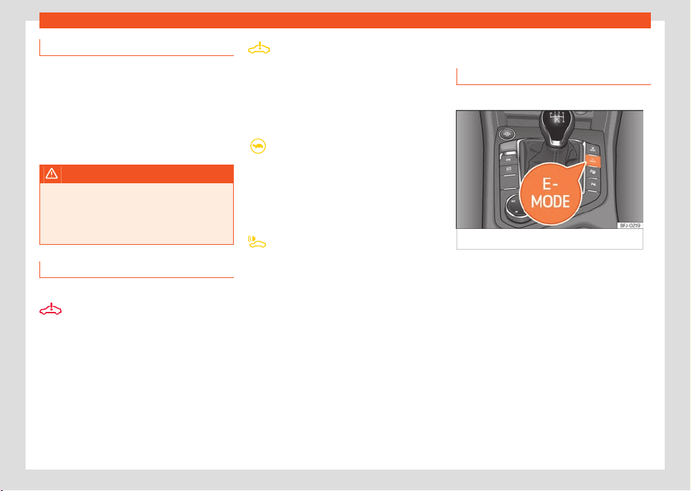
156
Driving
Vehicle sound
✓ V
alid for: hybrid vehicles
The electric drive makes much less noise than
a combustion engine. In the versions for some
countries, artificial vehicle sound is generated
to allow the vehicle to be heard better from
the outside. At higher speeds, when the noise
produced by the tyres and the wind increases,
the vehicle's sound automatically fades out.
WARNING
During electric driving, the auditory percep-
tion of the v
ehicle by other road users may
be much lower. This is especially true in traf-
fic-restricted areas and when manoeuvring
or reversing. Accident hazard!
Troubleshooting
✓ Valid for: hybrid vehicles
Drive: Fault! Stop the vehicle safely
The warning lamp lights up red.
There is a fault in the vehicle’s drive system.
The vehicle's drive system is no longer availa-
ble. Park the vehicle in a safe place as soon as
possible. Seek professional assistance.
Error: Hybrid system. Visit the work-
shop
The w
arning lamp lights up yellow.
There is a fault in the vehicle’s drive system.
Drive slowly to a specialised workshop to have
the fault repaired.
Power limited
The w
arning lamp lights up yellow.
Performance limited. The high-voltage battery
may not be suciently charged or may have
reached its operating temperature limit, for ex-
ample in very cold outside temperatures.
Vehicle sound: Fault! Pedestrians can-
not hear the v
ehicle. Visit a workshop
The warning lamp lights up yellow.
There is a vehicle sound fault. Drive with utmost
care, as other road users may not be able to
hear the electric vehicle. Go immediately to a
specialised workshop to have the fault repaired.
Operating mode selection
Operating mode selection
✓ Valid for: hybrid vehicles
Fig.120 Centr
e console: E-MODE button.
The vehicle has dier
ent operating modes so
that it can always be optimally adjusted to ev-
ery situation while driving. Once the drive sys-
tem has been turned on, and provided that all
of the operating conditions required for this pur-
pose have been met, the E-MODE operating
mode is always activated in the first instance
for electric driving.
Operating mode selection
●
Switch on the drive system.
●
Press the E-Mode button on the centre con-
sole ›››Fig.120.
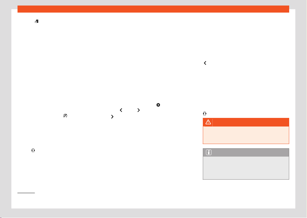
Driving
157
Operating mode selection
1)
The displayed symbol varies depending on the active operating mode and the charge level of the high-voltage battery.
=
E-MODE (driving in electric mode)
1)
In the E-MODE el
ectric driving mode, the vehi-
cle basically drives in electric only mode. To
the extent possible, the vehicle's combustion
engine is not used.
All of the following conditions must be met for
E-MODE to be activated:
●
The high voltage battery has a sucient
charge level.
●
The vehicle speed is lower than 130 km/h (80
mph).
●
The high voltage battery temperature is
above -10°C.
If, while driving in E-MODE mode, the necessary
conditions are no longer met, the combustion
engine starts and electric driving is suspended.
In this case, the indicator
lights up on the
instrument clust
er display.
The combustion engine starts when a kick-
down occurs in E-MODE. However, E-MODE re-
mains activated.
Hybrid
(use the battery's charge)
1)
This is the oper
ating mode that allows you to
save most fuel.
The operating mode control unit tries to make
the most of the battery charge. For this pur-
pose, with active directions the navigation data
are also accessed.
In this operating mode, the electric motor and
the combustion engine shar
e the work of driv-
ing the vehicle.
In hybrid operating mode, the power from
the battery charge is used optimally. If route
guidance is activated, the vehicle may autono-
mously recharge the high-voltage battery using
the combustion engine.
Manual control of the battery charge
Manual control of the battery charge is only
possible in Hybrid operating mode. The option
selected by the user is only valid until the igni-
tion is switched o or the vehicle is switched to
Hybrid mode or E-MODE.
Press the function button
and use the sym-
bol
s
, = and to control the battery charge:
Pressing this symbol selects a higher the-
or
etical charge level. The vehicle tries to
reach that new theoretical high-voltage
battery charge level while driving. The vehi-
cle is powered by the combustion engine. If
the combustion engine has “excess” power,
it is used to charge the high-voltage bat-
tery.
This option increases fuel consumption.
SEAT therefore recommends using the
charging socket to charge the high-voltage
battery, whenever possible ›››page71.
The high-voltage battery charge level is
k
ept at around the current level while driv-
ing. If you accelerate harder or increase
the vehicle speed, the combustion engine
starts up. When permitted by the driver’s
demand for acceleration and the vehicle
speed, the vehicle switches back to electric
mode.
Pressing this symbol selects a lower theo-
retical charge level. The vehicle only uses
the battery's charge when it is above the
selected theoretical charge level. The rest
is kept until the end of the journey.
Show the active operating mode
The operating mode active at any given time is
displayed on the instrument cluster display, e.g.
.
WARNING
Switching to a dier
ent operating mode
while driving can distract you from trac
conditions and cause accidents.
Note
Information about the operating mode that
is curr
ently active is displayed on the instru-
ment cluster display, along with the charge
level of the high-voltage battery.
158
Driving
1)
Only in vehicles with Keyless Access.
Troubleshooting
✓ V
alid for: hybrid vehicles
E-MODE operating mode is not availa-
bl
e
The indicator lamp lights up in white.
The E-MODE operating mode
(driving in
el
ectric mode) cannot be used temporarily be-
cause one or more conditions are not met.
●
The conditions must be met to use the E-
MODE operating mode.
Start-Stop system
Description and operation
Not valid for PHEV hybrid vehicles
The Start-Stop system helps you to save fuel
and reduce CO
2
emissions.
In Start-Stop mode, the engine will automati-
cally switch o when the vehicle stops or is
stopping. The ignition remains switched on. The
engine automatically switches back on when
required.
In this scenario, the light of the
button remains lit.
1)
When the ignition is s
witched on, the Start-Stop
function is automatically activated.
Control lamps
The Start-Stop system is available, the
aut
omatic engine shutdown is active.
The Start-Stop system is not available or
has been disconnected.
Stopping and starting the engine
Vehicles with a manual gearbox:
●
When the vehicle is stopped, put it into neu-
tral and release the clutch pedal. The engine
will stop. The warning lamp
will light up on
the displ
ay. The engine may be stopped before
the vehicle comes to a standstill (approximately
7 km/h).
●
When you depress the clutch pedal, the en-
gine will start again. The indicator lamp goes
out.
Vehicles with an automatic gearbox:
●
Brake until the vehicle has come to a stand-
still, and keep your foot on the brake pedal
or activate the Auto Hold system so that the
vehicle remains braked. The engine will stop.
The warning lamp
will appear on the dis-
pl
ay. The engine can be stopped before stop-
ping completely (approximately 7 or 2 km/h de-
pending on the vehicle's gearbox).
●
When you take your foot o the brake pedal
the engine will start up again. The indicator
lamp goes out. With the Auto Hold system, the
engine will not start if you remove your foot
from the brake pedal. The car starts when you
press the accelerator pedal.
Basic requirements for the start/stop mode
●
The driver door must be closed.
●
The driver's seat belt must be fastened.
●
The bonnet must be closed.
●
The engine has reached operating tempera-
ture.
●
The reverse gear must not be engaged.
●
The vehicle must not be on a very steep
slope.
The engine does not turn o for various rea-
sons
Before stopping the vehicle, the system verifies
whether certain conditions are met. The engine
does not switch o, in the following situations
for example:
●
The engine has not yet reached the required
temperature for the Start-Stop mode.
●
The temperature selected on the climate
control has not been reached.
●
The interior temperature is very high/low.
●
De-icing function button
activated.
●
Park assist is switched on.
●
The battery is very low.
Driving
159
Start-Stop system
●
The steering wheel is overly turned or is being
t
urned.
●
If there is a danger of misting.
●
After engaging reverse gear.
●
In case of a very steep gradient.
is displayed on the instrument cluster
scr
een; it is also displayed in the driver informa-
tion system,
.
The engine st
arts by itself
When stopped, the normal system mode may
be interrupted in the following situations. The
engine restarts without the driver's intervention.
●
The interior temperature diers from the tem-
perature selected on the climate control.
●
Defrost function button activated
.
●
The brake is pressed several times in a row.
●
The battery is not charged enough.
●
High electricity consumption.
Additional inf
ormation related to the auto-
matic gearbox
The engine stops when the selector lever is in D,
N and S, as well as in Tiptronic mode. With the
selector lever in P, the engine will also remain
switched o when you take your foot o the
brake pedal.
In order to start the engine up again the ac-
celerator must be pressed, or another gear en-
gaged or the brake released.
If the selector lever is placed in R while stopped,
the engine will start up again.
Change from D to P to prevent the engine from
accidentally starting when passing through R.
Additional information about vehicles with
Adaptive Cruise Control (ACC)
In vehicles with ACC function, the engine will
start up again in certain operating conditions if
the radar sensor detects that the vehicle ahead
drives o again.
WARNING
●
Never switch the engine o until the v
ehi-
cle is stationary. The operation of the brake
and steering will not be fully guaranteed.
More force will be needed to turn the steer-
ing wheel or to brake. You could suer an
accident and even serious injuries.
●
To avoid injury, make sure that the Start-
Stop system is switched o when working in
the engine compartment ›››page159.
NOTICE
The Start-Stop system must always be
s
witched o when driving through flooded
areas ›››page148.
Note
●
In vehicles with an automatic gearbox,
you can contr
ol whether the engine should
switch o or not by reducing or increasing
the brake force applied. While the vehicle re-
mains stopped, the engine will not stop if the
brake pedal is slightly pressed, in trac jams
with frequent stopping and starting for exam-
ple. As soon as strong pressure is applied to
the brake pedal, the engine will stop.
●
When stopped, the brake pedal must be
k
ept pressed to ensure that the vehicle does
not move.
●
If the engine “stalls” with a manual gear-
box, it can be directly started up again by
immediately pressing the clutch pedal.
●
If the lever is placed in position D, N or S
after engaging reverse gear, 10km/h (6mph)
in a forwards direction must be reached for
the system to be in a condition to stop the
engine.
Manually connecting and discon-
necting the Start-Stop system
Not valid for PHEV hybrid vehicles
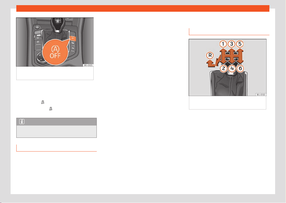
160
Driving
Fig.121 Centr
e console: Start-Stop system
button.
If you do not wish to use the system, you can
s
witch it o manually:
●
To manually switch on/o the Start-Stop sys-
tem, press the
button ›››Fig.12
1
The button symbol
remains lit up in yellow
when the syst
em is switched o.
Note
The system switches on every time the en-
gine is t
urned o voluntarily.
Troubleshooting
Not valid for PHEV hybrid vehicles
Indications for the driver on the instrument
cluster screen
Start-Stop system deactivated.
Start the engine manually
●
This indication shows that the Start-Stop sys-
tem cannot restart the engine.
This happens for 2 reasons: if the driver's door
has been opened or if the driver has unbuckled
the seat belt.
Start-Stop system: Fault! Function
not available
●
There is a fault in the Start-Stop system. Take
the vehicle to a workshop to have the fault re-
paired.
Manual gearbox
Changing gears
Fig.122 Diagr
am of a 6-speed manual
gearbox.
Gear positions are indicated on the gear lever
›››Fig.122.
●
Depress the clutch and keep your foot as far
as it will go
.
●
Move the gear lever to the desired position.
●
Release the clutch.
Engaging reverse gear
Only engage reverse gear when the vehicle is
stopped.
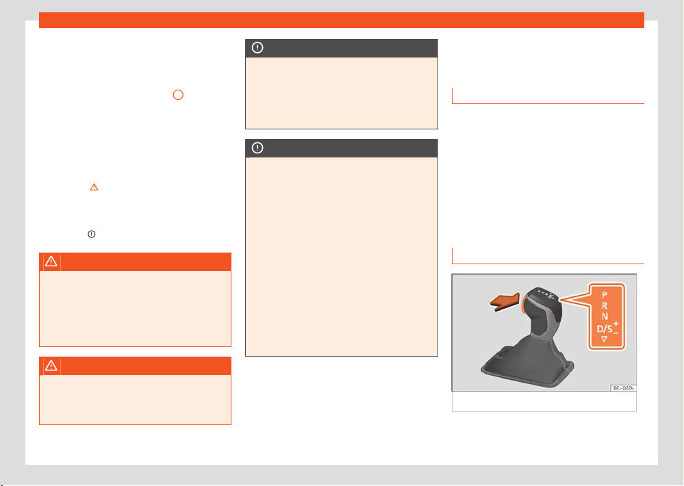
Driving
161
DSG automatic transmission
●
Depress the clutch and keep your foot as far
as it will go
.
●
With the gear lever in neutral, push it down,
move it all the way to the left and then forwards
to select reverse gear ›››Fig.122
R
.
●
Release the clutch.
Changing t
o lower gears
When driving, you should always change down
through the gears progressively, i.e. to the gear
immediately below when engine RPM is not
tool high ›››
. Skipping one or several gears
when changing do
wn through the gears at high
speed or high RPM can cause damage to the
clutch and gearbox, even if the clutch is de-
pressed ›››
.
WARNING
If the engine is running, the vehicle starts
mo
ving as soon as a gear is engaged and the
clutch pedal is released. This also happens if
the electronic parking brake is switched on.
●
Never engage reverse gear while the vehi-
cle is in motion.
WARNING
Changing down through the gears incor-
r
ectly by selecting a gear that is too low
can lead to loss of control of the vehicle and
cause accidents and serious injuries.
NOTICE
Engaging a gear that is too low when driving
at high speed or at high engine RP
M can
cause considerable damage to the clutch
and gearbox. This can happen even if the
clutch pedal is kept depressed and the gear
is not engaged.
NOTICE
Consider the following to avoid damage and
pr
emature wear:
●
Do not rest your hand on the gear lever
while driving. The pressure exerted by the
hand is transmitted to the gearbox forks.
●
Do not rest your foot on the clutch pedal;
even if the pressure seems insignificant, it
can cause premature wear of the clutch disc.
Use the footrest when not changing gears.
●
Make sure the vehicle is completely stop-
ped before engaging reverse gear.
●
When changing gears, always fully de-
press the clutch.
●
Do not “ride” the clutch with the engine
running when the vehicle is stopped on an
uphill slope.
DSG automatic transmis-
sion
Intr
oduction
Your vehicle is equipped with an electronically
controlled manual gearbox. Torque between
the engine and the gearbox is transmitted via
two independent clutches. They replace the
torque converter found on conventional auto-
matic gearboxes and allow for smooth, uninter-
rupted acceleration of the vehicle.
The Tiptronic system allows the driver to
change gears manually ›››page163, Chang-
ing gear in Tiptronic mode.
Gear selector positions
Fig.123 Sel
ector lever lock.
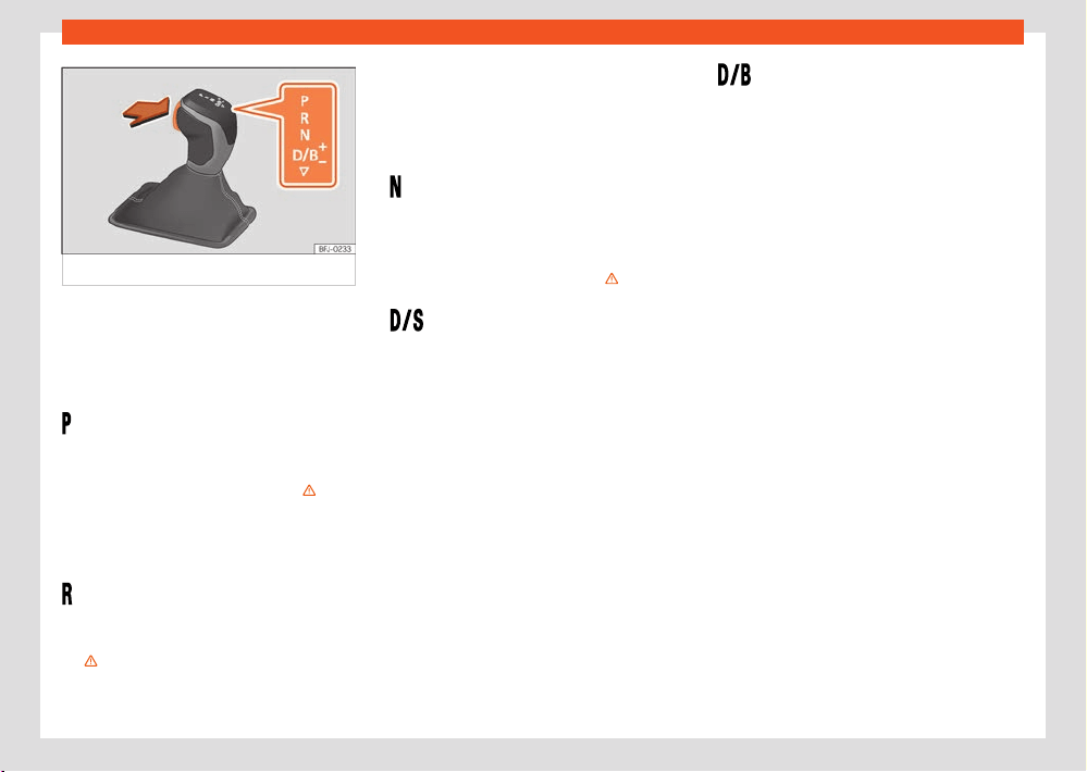
162
Driving
Fig.124 Sel
ector lever lock (hybrid vehicles).
The selector lever position is shown when the
corr
esponding sign lights up. With the selector
lever in the manual gearbox positions M, D and
S, the engaged gear is also shown on the dis-
play.
- Parking lock
When the l
ever is put in this position, the drive
wheels are locked. The lever should only be put
in P when the vehicle is stationary ›››
.
T
o put the lever in P or take it out of P , the
locking button must be pressed and held and
the brake pedal pressed simultaneously.
– Reverse gear
R
everse gear must be engaged only when the
vehicle is stationary and the engine is idling
›››
.
To move the lever to position R, the l
ock button
must be pressed and held while pressing the
brake pedal at the same time. The reverse lights
come on when the lever is in the R position with
the ignition on.
– Neutral
In this position, the gear is in neutr
al.
Press the brake pedal to move the lever from
N to D/S when the vehicle is stationary or at
speeds below 3km/h (2mph) ›››
.
– Permanent forward drive position
The l
ever in the D/S position enables the gears
to be operated in normal mode (D) or sport
mode (S). To select Sport mode S, move the
lever backwards. Pushing the lever again will
select normal mode D. The selected driving
mode is shown on the instrument panel display.
In normal mode (D), the gearbox selects the
best gear ratio. This depends on the engine
load, the road speed and the dynamic gear
control programme (DCP).
Sport mode(S) should be selected for a sporty
driving style. This setting makes use of the en-
gine's maximum power output. When acceler-
ating the gear shifts will be noticeable.
Under certain circumstances (e.g. on mountain
roads) it can be advantageous to switch tip-
tronic mode ›››page163, to adapt the gears
to suit the road conditions.
Permanent forward drive position
(v
alid for hybrid vehicles)
The lever in the D/B position allows the gears to
be operated in coasting or recuperation mode.
Push the lever backwards to select mode B.
Pushing it again will return to mode D.
●
In mode D: if the accelerator is not pressed,
the car moves by its own inertia.
●
In mode B: the vehicle is slowed by the elec-
tric motor, taking advantage of the energy to
recharge the high-voltage battery.
Selector lever lock
In P or N, the lever lock prevents a gear range
from being engaged, and prevents the vehicle
from moving o accidentally.
To release the gear lever lock, press and hold
the brake pedal with the ignition on. At the
same time, press the lever lock in the direction
of the arrow ›››Fig.123.
As a reminder to the driver, when the lever is in
positions P or N the following indication will be
shown on the screen:
When stationary, apply foot brake
while selecting a gear.
The lever is not locked if it is moved quickly
through position N (e.g. when shifting from R
to D). This makes it possible, for instance, to
“rock the vehicle backwards and forwards” if it
is stuck in snow or mud. The lever lock engages
automatically if the brake pedal is not pressed
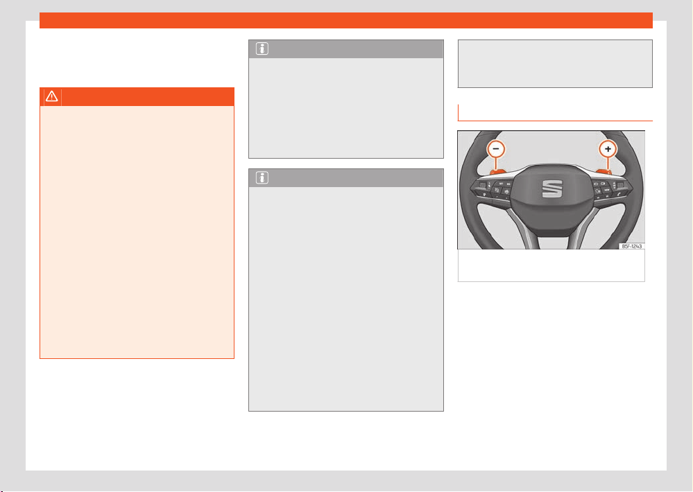
Driving
163
DSG automatic transmission
and the lever is in position N f
or more than
about one second at a speed of less than 5
km/h (3mph).
WARNING
●
Take care not to press the accelerator
pedal when the v
ehicle is stopped. The vehi-
cle could start moving immediately (in some
cases even if the parking brake is engaged)
resulting in the risk of an accident.
●
Never move the lever to R or P when driving.
Failure to follow this instruction could result
in an accident or failure.
●
With the lever in any position (except P),
the foot brake must be pushed down when-
ever the engine is running. This is because an
automatic gearbox still transmits power even
at idling speed.
●
While you are selecting a gear and the ve-
hicle is stopped with the engine running, do
not accelerate. Failure to follow this instruc-
tion could result in an accident.
●
As a driver you should never leave your ve-
hicle if the engine is running and a gear is
engaged. Switch on the electronic parking
brake and select the parking lock (P).
Note
●
If the lever is moved accidentally to N when
driving, r
elease the accelerator and let the
engine speed drop to idling before selecting
gear range D or S again.
●
Should the power supply to the lever be in-
terrupted in positionP, it will not be possible
to move the lever. If this should happen the
manual release can be used ›››page167.
Note
●
If the lever lock does not engage, there is a
f
ault. The transmission is interrupted to pre-
vent the vehicle from accidentally moving.
Follow the procedure below in order for the
lever lock to engage again:
–
With a 6-speed gearbox: press the brake
pedal and release it again.
–
With a 7-speed gearbox: press the brake
pedal. Move the lever to positionP orN and
subsequently engage a gear.
●
If a gear has been selected, the vehicle
does not move forwards or back. Proceed to
the next mode:
–
When the vehicle does not move in
the required direction, the system may not
have the gear range correctly engaged.
Press the brake pedal and engage the gear
range again.
–
If the vehicle still does not move in the re-
quir
ed direction, there is a system malfunc-
tion. Seek specialist assistance and have
the system checked.
Changing gear in Tiptronic mode
Fig.125 St
eering wheel: automatic gearbox
levers
Tiptronic gives the driver the option to change
gears manually.
When you change t
o the Tiptronic programme,
the vehicle remains in the currently selected
gear. This is possible as long as the system is
not changing gear automatically due to a traf-
fic situation.
Using Tiptronic with the selector lever
It is possible to change to Tiptronic mode, both
when the vehicle is stopped and while driving.
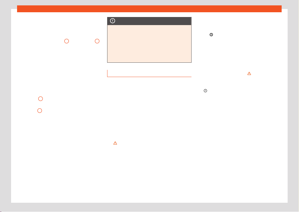
164
Driving
●
Starting from the D/S position, mo
ve the lever
to the right. The instrument panel will show
whether the lever is in manual or Tiptronic
mode (e.g. M4).
●
Move the lever forwards
+
or backwards
–
to change up or down a gear.
●
To exit Tiptronic mode, move the lever to the
l
eft.
Using Tiptronic with the steering wheel pad-
dles
The gearshift paddles can be used when the
selector lever is in the D/S or M (Tiptronic) posi-
tions.
●
Press the
+
gear shift paddle to change up
a gear ›››Fig.125.
●
Press the
–
gear shift paddle to change
do
wn a gear.
●
To exit the Tiptronic mode, pull the right-hand
lever towards the steering wheel for approxi-
mately 1 second or move the lever to the left.
If the paddles are not operated for some time
and the lever is not in the Tiptronic selection
position, it will automatically exit from Tiptronic
mode.
NOTICE
●
When accelerating, if a higher gear is
not sel
ected, it will automatically change
shortly before reaching the maximum per-
mitted RPM.
●
Also, if a lower gear is selected, the system
will not change until it detects that the en-
gine will not reach its maximum RPM.
Driving with an automatic gearbox
The gearbox changes gear ratios automati-
cally as the vehicle moves.
The engine can only start with the selector
lever in positionP or N. At low temperatures
(below -10°C), the engine can only start with
the selector lever in position P.
Driving down hills
Under certain circumstances it may be advan-
tageous to use the Tiptronic mode to select the
gear manually according to driving conditions
›››
.
St
op/Park
On level ground, just use the lever to engage
position P. On slopes you should first apply the
parking brake and then set the lever to P. This
makes it easier to remove the lever from posi-
tion P when starting.
If the driver door is opened and the lever is not
in position P, the v
ehicle could move. The fol-
lowing warning is displayed on the instrument
panel:
Gear change: selector lever
in the drive position!. Additionally, a
buzz
er will sound.
Stopping on a downhill
Always apply the brake pedal firmly to prevent
the vehicle from moving; if necessary, apply the
electronic parking brake ›››
.
Do not accel
erate while a range of gears is en-
gaged to prevent the car from rolling downhill
›››
.
St
arting o uphill with the Auto Hold function
●
Once you have engaged a gear, take your
foot o the brake pedal and gently press the
accelerator.
Starting o uphill without the Auto Hold
function
●
Pull on the electronic parking brake button.
●
Once you have engaged a gear, gently press
the accelerator and pull on the electronic park-
ing brake button.
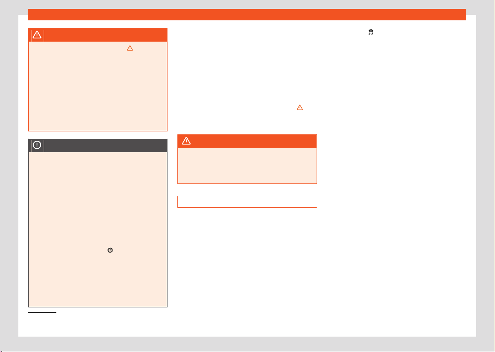
Driving
165
DSG automatic transmission
1)
Vehicles without a driver information system: the w
arning lamp flashes slowly. Vehicles with a driver information system: the warning lamp remains on.
WARNING
Observe the safety warnings ››› in Gear
sel
ector positions on page163.
●
Never allow the brake to rub and do not use
the brake pedal too often or for long periods,
as the brakes can overheat. This reduces
the braking power, increases the braking dis-
tance or even causes a brake system fault.
●
If you have to stop on a hill, keep the vehi-
cle’s brakes applied with the brake pedal or
parking brake.
NOTICE
●
If you stop the vehicle on a gradient, do not
att
empt to stop it from rolling by depressing
the accelerator when a gear has been selec-
ted. This could cause overheating and dam-
age the automatic gearbox.
●
If you allow the vehicle to roll with the lever
in position N and the engine o, the auto-
matic gearbox will be damaged by lack of
lubrication.
●
In certain driving situations or trac condi-
tions, the gears could overheat and be dam-
aged! If the warning lamp
lights up, stop
the v
ehicle as soon as you can and wait for
the gearbox to cool ›››page167.
●
If the gearbox operates with the backup
programme, take the vehicle to a specialised
workshop and have the fault repaired with-
out delay.
Kick-down
The kick
-down device provides maximum ac-
celeration when the gear selector lever is in the
positionsD, S or in Tiptronic mode.
When the accelerator pedal is pressed right
down, the automatic gearbox will shift down
to a lower gear, depending on road speed
and engine speed. This takes advantage of the
maximum acceleration of the vehicle ›››
.
The upshift t
o the next higher gear is delayed
until the engine reaches maximum rpm.
WARNING
Please note that if the road surface is slip-
pery or w
et, the kickdown feature could
cause the driving wheels to spin, which could
result in skidding.
Launch-control program
The Launch-control programme enables maxi-
mum acceleration from a standstill.
Condition: the engine must have reached oper-
ating temperature and the steering wheel must
not be turned.
The engine speed for Launch-control is dier-
ent for petrol and diesel engines.
To use the Launch-control it is necessary to
disconnect the traction control (TCS) using the
infotainment system menu ›››page37. The
warning lamp
will stay switched on or will
flash sl
owly depending on whether or not the
vehicle has a driver information system.
On vehicles with the driver information system,
the ESC lamp lights up permanently and the
corresponding text message Stability con-
trol deactivated (temporary) appears on
the instrument panel to indicate the deactiva-
tion status.
●
With the engine running, switch o tr
action
control (TCS) ›››page175
1)
.
●
Press the brake pedal with your left foot and
hol
d it down for at least one second.
●
Turn the selector lever to the S or Tiptronic
position, or else select the sport driving mode
from the Drive Profile.
●
With your right foot, press the accelerator
down to the full throttle or kick-down posi-
tion. The engine speed will stabilise at about
3,200rpm (petrol engine) or about 2,000rpm
(diesel engine).
●
Take your left foot o the brake pedal. The
vehicle starts with maximum acceleration.
166
Driving
WARNING
●
Always adapt your driving style to the
tr
ac conditions.
●
Only use the Launch control programme
when road and trac conditions permit, and
make sure your manner of driving and accel-
erating the vehicle does not inconvenience
or endanger other road users.
●
Make sure that the ESC remains switched
on. Please note that when the TCS and ESC
are deactivated, the wheels may start to
spin, causing the vehicle to lose grip. Acci-
dent hazard!
●
After moving o, the ESC “sport” mode
should be deactivated by briefly pressing the
button.
Note
●
After using the Launch control programme,
the t
emperature in the gearbox may have in-
creased considerably. In this case, the pro-
gram may be out of service for a few minutes.
The program may be used again once the
cooling phase is complete.
●
Accelerating with the Launch control pro-
gramme places a heavy load on all parts of
the vehicle. This can result in increased wear
and tear.
Inertia mode
The inertia mode all
ows you to travel certain
distances without using the accelerator, which
saves fuel. Plan ahead and use the inertia
mode to let the vehicle roll.
Activation of the inertia mode
Condition: lever in position D, slopes of
less than 12% and speeds between 20 and
130km/h (12 and 80mph).
●
Gently take your foot o the accelerator.
The indication will be shown on the instrument
panel
, the engaged gear and current con-
sumption will disappear and the w
ord Inertia
will appear.
The gears will automatically disengage and the
vehicle will roll freely, without the eect of the
engine brake. While the vehicle rolls, the engine
runs at idling speed.
Stopping inertia mode
●
Press the brake or the accelerator pedal.
T
o take advantage of the engine's inertia mode,
simply remove your foot from the accelerator.
Applying both the inertia mode (= prolonged
section with less energy) and inertia discon-
nection (= shorter section without the need for
fuel) facilitates improved fuel consumption and
emission balance.
If the vehicle has SEAT Driv
e Profile
›››page170, the inertia mode can be acti-
vated in Normal, Eco and Individual modes.
In Eco mode, it is activated whenever the op-
erating conditions are met, regardless of the
smoothness with which the foot is removed
from the accelerator.
WARNING
●
If the inertia mode has been switched on,
t
ake into account, when approaching an ob-
stacle, that the vehicle will not decelerate in
the usual manner: risk of accident!
●
When using inertia mode while travelling
down hills, the vehicle can increase speed:
risk of accident!
●
If other users drive your vehicle, warn them
about inertia mode.
NOTICE
The driver message Inertia is only displayed
with the curr
ent consumption. In inertia mode
the gear will no longer be displayed (for ex-
ample D or E will appear instead of D7 or E7).
NOTICE
The operation of the inertia mode in combi-
nation with hybrid engines can cause the
combustion engine t
o switch o.
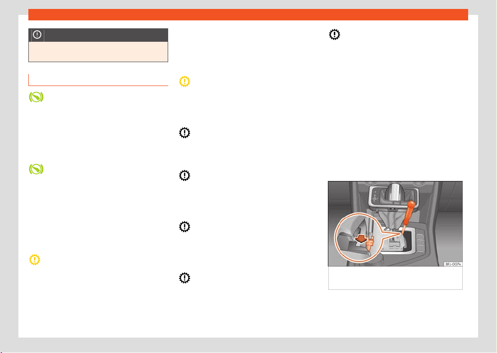
Driving
167
DSG automatic transmission
NOTICE
The inertia mode will be automatically dis-
connect
ed on gradients steeper than 15%.
Troubleshooting
The engine does not start
The indicat
or lamp lights up green.
The brake is not depressed, e.g. when trying to
change the gear selector lever.
●
To select a gear range, press the brake
pedal.
Selector lever lock
The contr
ol lamp flashes green.
The selector lever locking button is not en-
gaged. The vehicle is prevented from moving
forwards. Engage the selector lever lock.
Indications on the instrument cluster display:
Clutch
Clutch overheated! Please stop!
●
The clutch has overheated and could be
damaged. St
op and wait for the gearbox to
cool with the engine at idling speed and the
selector lever in position P. When the warning
lamp and the driver message switch o, have
the fault corrected by a specialised workshop
without del
ay. If they do not turn o, do not
continue driving. Seek specialist assistance.
Faults in the gearbox
Gearbox: Fault! Stop the vehi-
cle and place the lever in the P
●
There is a fault in the gearbox. Stop the vehi-
cl
e in a safe place and do not continue driving.
Seek specialist assistance.
Gearbox: System fault! You may
continue driving
●
Have the fault corrected by a specialised
w
orkshop without delay.
Gearbox: System fault! You can
continue driving with restrictions.
Reverse gear disabled
●
Take the vehicle to a specialised workshop
and hav
e the fault repaired.
Gearbox: System fault! You can
continue driving in D until switch-
ing off the engine
●
Park the vehicle in a safe place. Seek special-
ist assist
ance.
Gearbox: too hot. Adapt your
driving accordingly
●
Continue driving at moderate speeds. When
the w
arning lamp switches o, you can con-
tinue driving in a normal manner.
Gearbox: press the brake and
engage a gear again
●
If the warning was caused by the temperature
of the gearbo
x, this driver message will be dis-
played when the gearbox has cooled again.
Back-up programme
If all the gear positions are shown over a light
background on the instrument cluster, there is
a system fault and the automatic gearbox will
operate with the backup programme. It is still
possible to drive the vehicle, however, at low
speeds and within a selected range of gears.
Driving in reverse gear may not be possible.
Manual release of the selector lever
Fig.126 Selector lever: manual release from
position P.
In the event of a power failure when starting
(e
.g. discharged battery), the lever will remain
locked in position P. To move it to position N
168
Driving
to move the vehicle, there is an emergency re-
l
ease device under the centre console, on the
right side. Releasing the selector lever requires
a certain degree of practical skill.
Removing the cover from the selector lever:
●
Connect the electronic parking brake ›››
.
●
Carefully pull the corners of the selector lever
boot and twist it up
wards over the lever handle.
Releasing the selector lever:
●
Using the flat part of a screwdriver, press the
yellow tab sideways and keep it pressed down
›››Fig.126.
●
Press the lock button on the selector
lever and move it to positionN.
●
After completing the emergency release, re-
attach the selector lever boot to the gearbox
console.
WARNING
Do not move the lever from position P if the
parking br
ake is not firmly engaged. If you
still think the car could move, press the brake
pedal. Danger! The vehicle could move in an
unforeseen way and cause an accident or
serious injury.
Driving on slopes
Hill Hold Control (HHC)
When driving up a slope or driving in Oroad
with the lever in position D/S, stopping the vehi-
cle switches on the hill hold control.
When the brake pedal is released, the assistant
keeps the vehicle’s brakes applied for a few
seconds to give the driver time to press the ac-
celerator pedal and continue driving.
downhill assistant
Downhill speed control is activated when the
gear lever is in the D/S position and the brake is
applied. An appropriate lower gear is engaged.
The assistant attempts to maintain the speed
at which the vehicle was travelling when the
brake was applied, within logical limits. It may
be necessary to correct the speed by pressing
the brake.
The assistant can only change down as far as
3rd gear. It is possible that on very steep slopes
you may have to switch to tiptronic mode and
thus manually change down to 2nd or 1st gear
to take advantage of engine braking and take
the load o the brake system.
Downhill speed control is deactivated as soon
as the road levels out again or you press the
accelerator pedal.
On vehicles with a cruise control system
›››page182, downhill speed control is activa-
ted when you set a cruising speed.
WARNING
The downhill speed control cannot defy the
l
aws of physics. Therefore, speed cannot be
maintained constant in all situations. Always
be prepared to use the brakes!
Hill Descent Control (HDC)
✓ Valid for vehicles: 4Drive all-wheel drive
Hill Descent Control limits the speed on steep
descents by automatically braking all four
wheels, both when moving forward and in re-
verse. As the anti-lock brake system remains
active, it prevents the wheels from locking.
In vehicles with manual transmission, the Hill
Descent Control adapts the theoretical speed
without slowing the engine below its idling
speed.
Control lamps
It lights up white.
Hill Descent Contr
ol is active.
It lights up grey.
Hill Descent Control is not active. The
system is switched on, but is not adjust-
ing.
Driving
169
Steering
After starting the descent of a slope below
30km/h (
18 mph), speed is limited to a min-
imum of 2 km/h (1 mph) and a maximum of
30 km/h (18 mph). When appropriate, the driver
may increase or decrease the speed within the
limit by pressing the accelerator or the brake.
At this point the function is interrupted and, if
necessary, it is then reactivated.
Even so, it is imperative that the surface guaran-
tees sucient adhesion. For this reason, the Hill
Descent Control will not fulfil its function when,
for example, descending a slope with a frozen
or slippery surface.
Hill Descent Control is available when the dash
panel display shows the message
.
Hill Descent Contr
ol automatically intervenes if
the following conditions are met:
●
The vehicle engine is running.
●
The Oroad driving profile has been selec-
ted ›››page171. Driving at a speed below
30km/h (18mph) (the message
is shown on
the dash panel displ
ay).
●
The slope of the descent is at least 10% when
driving forward and 9% when driving in reverse.
●
The brake and the accelerator are not
pressed.
Hill Descent Control is deactivated on pressing
the brake and the accelerator or if the slope
is below 5%. The function can be switched o
manually in the infotainment system using the
> HDC function butt
on.
WARNING
Always be ready to brake. Otherwise, an ac-
cident coul
d occur and cause injury.
●
Hill Descent Control is only an auxiliary
system that in some situations may not su-
ciently brake the vehicle when going down a
slope.
●
The speed of the vehicle may increase de-
spite the intervention of Hill Descent Control.
Steering
Information relating to dierent vehi-
cle processes.
To make the vehicle more dicult to steal, al-
ways lock the steering before leaving the it.
Steering
On vehicles with electromechanical steering,
the power steering automatically adjusts ac-
cording to the driving speed, the steering wheel
torque and the orientation of the wheels. The
power steering only works when the engine is
running.
If the power steering does not work properly or
does not work at all, you will have to use much
more strength than usual to turn the steering
wheel.
Progressive steering
Depending on the vehicle’s features, it may or
may not incorporate a progressive steering sys-
tem.
In city trac you do not need to turn so much
on parking, manoeuvring or in very tight turns.
On roads or motorway, progressive steering
transmits, for example, in bends, a sportier,
more direct and noticeably more dynamic driv-
ing sensation.
Steering assist
This help assists the driver in critical situations. It
recommends turning the steering wheel to per-
form a corrective manoeuvre (counter-steer-
ing), turning slightly to avoid skidding ›››
.
WARNING
Steering assist helps the driver in critical sit-
uations. The driv
er is the person who has to
control the vehicle's steering at all times.
Troubleshooting
Steering fault
The w
arning lamp lights up red.
There is a fault in the power steering.
●
St
op driving! Seek specialist assistance.
●
Do not allow the vehicle to be towed on its
own wheels.

170
Driving
Steering fault
The contr
ol lamp lights up or flashes yellow.
The steering is stier or reacts more sensitively
than usual.
The control lamp lights up and remains lit:
●
Restart the engine and drive slowly for a short
distance. Contact a specialist workshop if the
control lamp remains on.
●
OR: the 12-volt battery was disconnected
and reconnected. Drive slowly for a short dis-
tance.
The control lamp flashes:
●
Turn the steering wheel slightly from one side
to the other.
●
Turn o the ignition and t
urn it on again.
●
Consider the warnings shown on the instru-
ment cluster display.
●
If the control lamp continues flashing after
the ignition has been switched on, do not con-
tinue driving. Seek specialist assistance.
SEAT Drive Profiles
Introduction
The driver can use the drive profiles to adapt
various features of the vehicle's systems to
the current driving situation, the desired driving
comfort and an economical driving style. Some
of the systems that can be adapted are the
suspension, st
eering, engine and air condition-
ing.
Depending on the vehicle’s equipment, various
drive profiles can be selected. The degree of in-
fluence of the vehicle's systems on the dierent
drive profiles depends on the vehicle’s equip-
ment.
Engine
Depending on the profile selected, the engine
responds more quickly or smoothly to the ac-
celerator being pressed. When the Eco profile is
selected, the Start-stop function is activated.
In vehicles with automatic transmission, the
gear change timing is changed to put the
changes at higher or lower revolutions. The Eco
profile activates the Inertia function, thereby re-
ducing consumption. The rest of the driving pro-
files will activate the inertia use function when
the gear selector lever is not in the S position,
depending on how the accelerator pedal is re-
leased ›››page166. When the vehicle is turned
on again, the function is activated by default to
reduce consumption.
With manual transmission, the ECO profile
changes the gear change recommendations to
facilitate more ecient driving.
Adaptive chassis control (DCC)
The DCC continuously adapts the damping of
the suspension system to the characteristics
of the road surface and the driving situation
(speed, acceleration and steering wheel angle)
according to the selected driving profile. In the
event of a fault in the DCC, the following mes-
sage is displayed on the instrument cluster dis-
play> Fault: damping adjustment.
Steering
The operation of the power steering is modified
and adapted to the selected profile to oer the
best behaviour for each situation.
Air conditioning
Climatronic can operate in Eco mode, espe-
cially restricting fuel consumption.
Adaptive Cruise Control (ACC)
Depending on the driving profile, the perform-
ance of the ACC to allow adaptation to a
speed that is more sporty or fuel consumption-
friendly.
Electronic Stability Control (ESC)
In the Oroad and Snow driving profiles, the
ESC adjusts to adapt to the characteristics of
the terrain.
PreCrash system
The PreCrash system adapts according to the
selected configuration ›››page47.
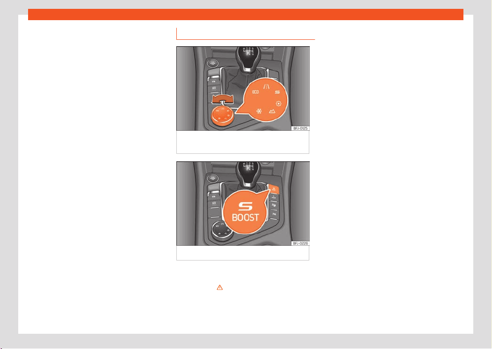
Driving
171
SEAT Drive Pr
ofiles
The Spor
t and Oroad driving profiles have
specific settings to adapt them to driving and
terrain characteristics .
Hill descent control assistant
This assistant can be activated or deactivated
in the Oroad profile. Hill Descent Control lim-
its the speed on steep descents by automati-
cally braking all four wheels, both when moving
forward and in reverse.
Hill Start Assist
It is possible to activate or deactivate this assis-
tant in the Oroad profile.
Parking assistants
The Oroad profile allows you to disable the
parking assistant to avoid warnings during o-
road driving.
Selecting a driving profile
Fig.127 Centr
e console: Driving Experience
button.
Fig.128 Centr
e console: S-BOOST button
The drive pr
ofile can be selected when the igni-
tion is switched on and the vehicle is stationary
or moving ›››
.
Selecting a driving pr
ofile
●
Turn the Driving Experience Button to select
the desired driving profile ›››Fig.127.
Hybrid vehicles
PHEV versions include the S-BOOST driving
profile as an exclusive additional.
Activate the profile:
●
Press and hold the button ›››Fig.128. The
indicator lamp on the button will light up and its
activation will also be indicated on the infotain-
ment system.
Deactivate the profile:
●
Press the S-BOOST button again.
●
Press the E-Mode button.
In hybrid versions the Eco, Normal and Sport
profiles do not change the behaviour of the en-
gine and hybrid system. This is only changed
with the S-BOOST profile.
Displaying the drive profile information
●
To display more information on the selected
drive profile, press Information in the info-
tainment system.
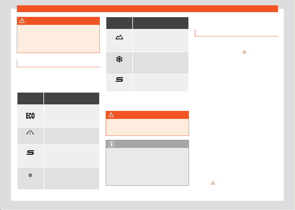
172
Driving
WARNING
Adjusting the driving pr
ofile while driving can
distract attention from trac and cause ac-
cidents.
●
Always drive as carefully and responsibly
as possible.
Characteristics of driving profiles
The icon of the selected profile is displayed on
the Infotainment System screen. The selector
indicates the selected profile using a LED light.
Driving pro-
fil
e
Characteristics
Places the vehicle in a low state
of consumption, f
acilitating a
fuel-saving driving style that is re-
spectful to the environment.
Normal
Oers a bal
anced driving experi-
ence, suitable for everyday use.
Sport
Provides a complete dynamic
perf
ormance in the vehicle, ena-
bling the user a more sporty driv-
ing style.
Individual
It allows you to personalise the
configur
ation. The functions that
can be adjusted depend on the
equipment fitted in the vehicle.
Driving pro-
fil
e
Characteristics
Oroad
a)
Maintains optimal o-r
oad driv-
ing by allowing the personalisa-
tion of the vehicle’s configuration
parameters.
Snow
a)
It adjusts the vehicle's behaviour
f
or driving on slippery road surfa-
ces, optimising grip and manoeu-
vrability.
BOOST
b)
This gives the vehicle and the
hybrid syst
em a dynamic overall
behaviour.
a)
Only for 4Drive models.
b)
Only for PHEV models.
WARNING
Your speed and driving style must always
be adjust
ed to visibility, weather, and trac
conditions.
Note
●
Regardless of the driving pr
ofile selected
when the ignition is switched o, all systems
will start up Normal mode. To select another
driving profile use the rotary (Driving Experi-
ence button).
●
Use of the Eco profile is not recommended
when driving with a trailer.
Braking system
Inf
ormation about the brakes
During the first 200 to 300 km, new brake
pads do not provide maximum braking power
and still have to “settle” ›››
. When running
in the brake pads, the emergency braking
distance is longer than after they have been
run in. During the run-in, avoid sharp braking
and situations that place a lot of demand on
the brakes, e.g. driving too close to another ve-
hicle.
Brake pad wear depends to a large extent on
the conditions in which the vehicle is used, and
driving style. If the vehicle is frequently used in
city trac and for short distances, or for sporty
driving, brake pad thickness should be checked
regularly at a specialist workshop.
Driving with wet brakes, e.g. after driving
through water, in heavy rain or after washing
the vehicle, braking performance may be af-
fected by wet brake discs, or even frozen discs
in winter. The driver should be ready to brake
harder.
If the brake discs and pads have a layer
of salt on them, the braking performance is
reduced and the braking distance increases.
When driving on salted roads without braking
for some time, the layer of salt should be re-
moved by carefully applying the brakes a few
times ››› .
Driving
173
Braking system
Corrosion on the br
ake discs and dirt on the
brake pads increase if the vehicle is left unused
for a long time, if it is not driven for many kilo-
metres. If corrosion is present, it is recommen-
ded to clean the discs and pads by braking
hard several times while driving at high speed.
Make sure that you do not endanger any other
vehicles or road users ›››
.
WARNING
Driving with worn brake pads or a defective
br
ake system can lead to accidents and seri-
ous injuries.
●
If you suspect that the brake pads are worn
or that the brake system is faulty, have the
brake pads checked immediately by a spe-
cialist workshop and replaced if they are
worn.
WARNING
The braking performance of new brake pads
is not optimal.
●
During the first 300 km, ne
w brake pads do
not provide maximum braking power and still
have to “settle”. This can be counteracted by
applying more pressure to the brake pedal.
●
When brake pads are new, drive with extra
care to reduce the risk of accidents, serious
injury or loss of control of the vehicle.
●
Only perform hard braking to clean the
brake system when permitted by the trac
situation. Do not endanger the occupants of
other vehicles. Accident hazard!
●
When running in new brake pads, do not
driv
e too close to other vehicles or cause sit-
uations that would require the brakes to be
applied heavily.
WARNING
When the brakes overheat, their braking per-
f
ormance drops and the braking distance in-
creases.
●
When driving downhill, particular demand
is placed on the brakes and they heat up
very quickly.
●
Before a long steep slope, reduce speed
and change down into a lower gear or range.
Therefore, using the engine brake relieves
the brakes.
●
If you wish to retrofit a front spoiler, inte-
gral trim or other accessories, ensure that
the air inlet around the brakes is not reduced,
as otherwise the brake system could over-
heat. Please also note the information on
brake fluid ›››page335.
WARNING
Wet, frozen or salt-covered brakes take lon-
ger to brake and increases the braking dis-
tance.
●
Test the brakes carefully.
●
Always dry the brakes and free them from
ice and salt by braking repeatedly, if permit-
ted by visibility, weather, road surface and
trac conditions.
WARNING
When braking manoeuvres are started auto-
matically, the br
ake pedal may move auto-
matically in the application direction. Do not
put your foot under the brake pedal. Risk of
injury!
Note
Never let the brakes “drag” by leaving your
f
oot on the pedal when it is not necessary
to brake. This can cause the brakes to over-
heat, resulting in increased brake travel and
wear. Please consider the important notes on
brake fluid ›››page335.
Note
Regularly check the thickness of the brake
pads visually thr
ough the holes in the rims
or from the underside of the vehicle. If nec-
essary, the wheels should be removed for
a more thorough inspection. SEAT recom-
mends visiting a SEAT dealership for this.
Troubleshooting
Defect in the brake system
The w
arning lamp lights up red. A message
may also be displayed.
St
op driving!

174
Driving
●
Inform a specialist workshop and request a
br
ake system inspection.
Brake pad wear indicator
The contr
ol lamp switches on yellow.
The front brake pads are worn.
●
Contact a specialised workshop immediately.
●
Get all the brake pads inspected and replace
if necessary.
Brake assist systems
Information relating to brake assist
systems
Brake assist systems can help the driver in crit-
ical driving or braking situations. The driver is
responsible for driving safely ›››
.
When the brake assist systems are regulating
the brakes, the brake pedal may move or make
noises. Even so, continue to brake with the nec-
essary force and control the trajectory of the
vehicle if necessary.
Depending on the equipment, the ESC and TCS
settings may be changed in the vehicle.
●
The ESC, ABS and TCS can only operate cor-
r
ectly if the four wheels are fitted with the stipu-
lated tyres ›››
.
●
If a fault occurs in the ABS, the ESC, TCS and
EDS al
so cease to function.
Electronic Stability Control (ESC)
The ESC helps to reduce the risk of skidding
and to improve stability in certain driving situa-
tions ›››
.
T
raction control (TCS)
The TCS reduces the driving force on skidding
wheels and adapts this force to suit the road
surface conditions. The TCS facilitates starting,
acceleration and hill climbing ›››
.
El
ectronic brake pressure distribution (EBV)
Electronic brake force distribution (EBV) regu-
lates the braking force between the front and
rear axles. Excessive braking of the rear axle is
avoided and the vehicle remains stable during
the braking operation.
Anti-lock braking system (ABS),
The ABS can prevent the wheels from locking
up under braking until shortly before the vehicle
comes to a stop, and helps the driver maintain
control of the steering and the vehicle ›››
.
Brake assist (BAS)
Br
ake assist (BAS) can help to reduce the brak-
ing distance. Brake Assist increases the pressure
exerted by the driver when the brake pedal is
depressed quickly in an emergency.
Electronic dierential lock (EDS and XDS)
The EDS automatically brakes skidding wheels
and transmits the driving force to the other driv-
ing wheels.
The XDS improves traction by applying the
brakes to keep the vehicle in its lane.
Multi-collision brake
The multi-collision brake automatically triggers
braking if the airbag control unit detects a colli-
sion in the event of an accident.
Automatic braking requirements:
●
The driver is not pressing the accelerator
pedal.
Tractor-trailer sway mitigation
If the vehicle is pulling a trailer, it will control the
following: tractor-trailers tend to sway. When
the swaying of the trailer is felt by the vehicle
and detected by the ESC, it will automatically
brake the towing vehicle within the limits of the
system and mitigate the sway. Tractor-trailer
sway mitigation is not available in all countries
›››page303.
Driving
175
Brake assist systems
1)
Valid for hybrid vehicles
Brake blending
1)
The r
egulated application of the brakes blends
the braking eect of the electric motor in en-
ergy recuperation and the mechanical braking
by the driver.
WARNING
Smart brake assist technology cannot over-
come the limits imposed by the l
aws of phys-
ics and only works within the limits of the sys-
tems. Driving at high speed on icy, slippery
or wed road surfaces can cause a loss of
control of the vehicle and serious injury to
the driver and passengers.
●
Adapt your speed and driving style at all
times to suit visibility, weather, road and
trac conditions. Never take any risk that
compromises safety.
●
Brake assist systems cannot prevent an ac-
cident if you are driving too close to other
vehicles.
●
Always use suitable tyres. Driving stability
depends on tyre grip.
WARNING
The eciency of the ESC can be significantly
r
educed if components or systems that af-
fect the driving dynamics are not properly
maintained or are not working properly. This
can particularly occur if changes are made
to the suspension or unauthorised rim/tyre
combinations are used.
●
Ensure that vehicle conversions and modi-
fications are only made by specialised work-
shops.
●
Always use suitable tyres. Driving stability
depends on tyre grip.
WARNING
When driving without a brake servo or with
r
estricted brake servo functions, the braking
distance can increase considerably and can
cause accidents and serious injuries.
●
If the brake servo is not working, the brake
pedal has to be pressed harder, as the brak-
ing distance increases due to the lack of as-
sistance from the servo brake.
Connecting and disconnecting the
ESC and TCS
The ESC is switched on automatically when the
engine is started, and only works when the en-
gine is running and includes the ABS, EDS and
TCS systems.
The TCS function should only be switched o in
situations in which traction is insucient.
Depending on the finishes and versions, there is
the possibility of disconnecting only the TCS or
activating the ESC in “Sport” mode.
Disconnecting and connecting the TCS
●
The TCS can be activated or deactivated
in the infotainment system using the function
button
> Driver assistance > ESC Menu
›››page37.
When the T
C is switched o, the control lamp
lights up on the instrument cluster.
Disconnecting and connecting the ESC in
“Spor
t” mode
●
The ECS in “Sport” mode can be activated
or deactivated in the infotainment system using
the function button
> Driver assistance >
ESC Menu ›››page37.
When “Sport” mode is connect
ed, the interven-
tions of the ESC to stabilise the vehicle, and the
traction control (TCS) interventions are limited.
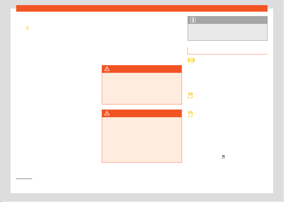
176
Driving
2)
Only for 4Drive models.
In vehicles with 4-wheel drive, the TCS is dis-
connect
ed completely . In addition, the control
lamp
lights up on the instrument cluster.
ESC in “Or
oad” mode
2)
Turn the (Driving Experience button) to se-
lect the Oroad profile to be switched on
›››page172. The interventions of the TCS, as
well as of the EDS and the ABS system adapt to
irregular terrain.
In the following exceptional situations it may
make sense to activate the Oroad mode to
allow the wheels to spin:
●
When “swinging” the vehicle to get it unstuck.
●
Driving in deep snow or on loose surfaces.
●
When driving on rough terrain with much of
the car
's weight is lifted o the wheels (axle
articulation).
●
Steep descents with braking on unpaved ter-
rain.
For your safety we recommend that you turn
o the Oroad mode when it is not absolutely
necessary.
To disconnect the Oroad mode, select a dif-
ferent driving mode.
ESC in “Snow” mode
2)
Use the rotary (Driving Experience button) to
select the Snow profile to be switched on
›››page172. Traction control system (TCS)
interventions adjust to the adhesion of snowy
roads.
To disconnect the Snow mode, select a dier-
ent driving mode.
WARNING
The ESC Sport mode should be activated
only when tr
ac conditions and the ability
of the driver allow it. Danger of skidding!
●
With ESC in Sport mode, the stabilising
function will be limited to allow for a sportier
drive. The vehicle may skid.
WARNING
You should only activate the Or
oad Mode
or disable the TCS if the experience of the
driver and trac conditions allow it. Danger
of skidding!
●
With the Oroad mode activated, the sta-
bilisation function is limited. In particular, if
the road is too smooth and slippery, the driv-
ing wheels could spin and the vehicle could
skid.
Note
If the TCS is disconnected or “Sport” mode
is sel
ected, the cruise control system will be
switched o.
Troubleshooting
The ABS does not work properly or does
not w
ork at all
The control lamp switches on yellow.
●
Contact a specialised workshop. The vehi-
cle’s brakes still work without the ABS.
The ESC or TCS is regulating
The contr
ol lamp flashes yellow.
ESC fault
The contr
ol lamp switches on yellow. The ESC
has been switched o.
There is a fault or defect.
●
Turn o the ignition and turn it on again.
●
If possible, drive for a short distance at 15-20
km/h (9-12 mph).
●
If the control lamp
is still on, go to a speci-
alised w
orkshop.
Driving
177
Brake assist systems
The brake assist systems make noises
When the described br
ake assist systems inter-
vene, you may hear noises.
WARNING
●
When the ignition is switched on, the sta-
t
us of the brake system and the brake assist
functions are automatically checked. The
control lamps on the instrument cluster light
up briefly and then go out. Any indicator
lamp that remains on indicates a fault. Seek
qualified technical assistance immediately.
●
If the brake system warning light
comes
on t
ogether with the
control lamp, the ABS
r
egulation function may not work and the
rear wheels may lock relatively quickly when
braking. This can lead to loss of control of
the vehicle! If possible, slow down and drive
slowly and carefully to the nearest specialist
workshop to have the brake system inspec-
ted. During this journey, avoid heavy braking
and any sudden manoeuvres.
●
If the control lamp
does not go out, or
comes on whil
e driving, it means that the ABS
is not working properly. The vehicle can only
be stopped using normal braking (without
ABS). In this case the protective ABS func-
tion will not be available. Go to a specialised
workshop as soon as possible.
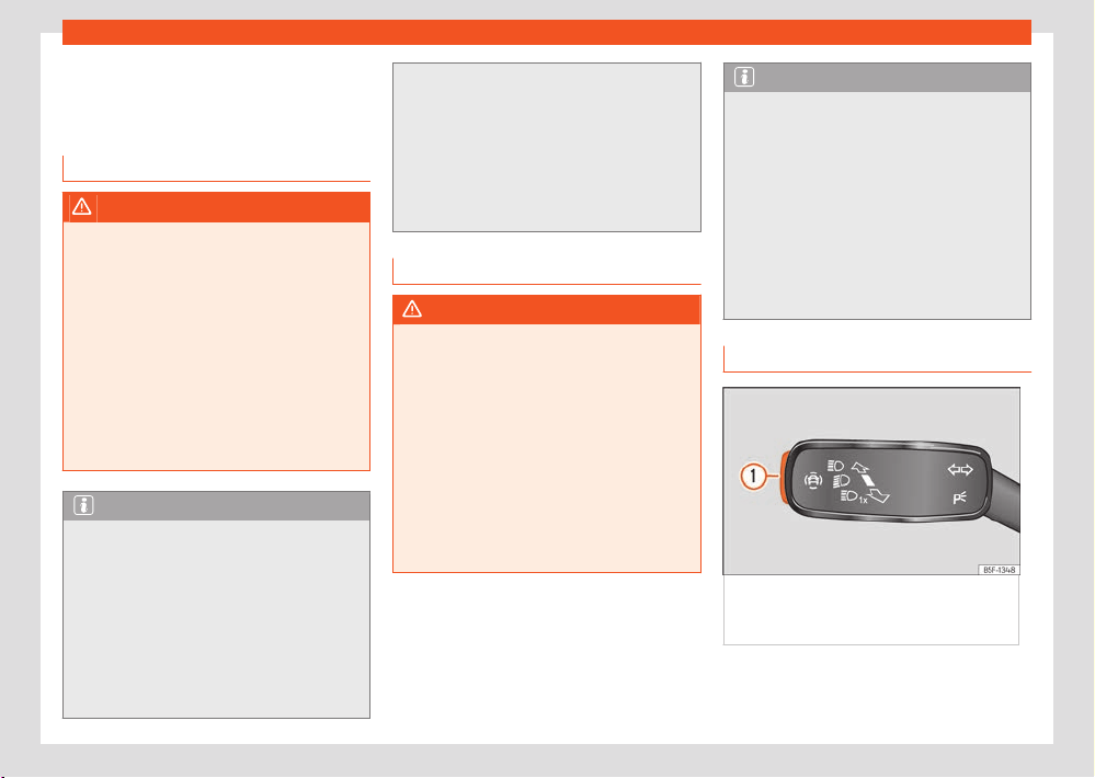
178
Assistant systems
Assistant systems
Gener
al notes
Safety advice
WARNING
●
Responsibility for driving rests with the
driv
er at all times. The drive assist systems
are not a replacement for driver attention.
Focus all your attention on driving and be
prepared to intervene at all times.
●
Use the drive assist systems only when
conditions allow. The driving style must al-
ways be suitable for the weather, visibility,
road and trac conditions.
●
In order for drive assist systems to react
correctly, sensors and cameras must oper-
ate without limitations. Please read the notes
on sensors and cameras in this chapter.
Note
●
Keep in mind the specific rul
es of each
country, especially when it comes to driving,
formation of an emergency corridor, braking
distance, speed, parking position, wheel po-
sition, etc. The driver is solely responsible for
always complying with the specific regula-
tions of each country.
●
The area in front of and around the radar
sensor should not be covered with adhesives,
additional headlights or similar items, as this
could have a negative impact on the oper-
ation of the assist
ants. If the vehicle is not
properly repaired or structural modifications
are made to it, the operation of the assistants
may be aected.
●
The repair and adjustment of sensors and
camer
as requires special knowledge and
tools. It is recommended to visit a SEAT deal-
ership for this purpose.
System limits
WARNING
●
Drive assist systems can not overcome the
l
aws of physics. Depending on the circum-
stances, a collision may not be avoidable.
●
Warnings, notices and indicator lamps
may not be displayed on time, or may be
displayed incorrectly, e.g. if a vehicle ap-
proaches too quickly.
●
Corrective interventions by drive assist
systems (e.g. interventions in the steering or
brakes) may be insucient or may never oc-
cur, depending on the circumstances. As a
driver, you must be prepared to act at all
times.
Note
●
Due to the system's detection limits in
the surr
oundings, the systems may not give
warnings or intervene on time, or they might
do so even if it is not desired. In addition, the
auxiliary systems may incorrectly interpret a
manoeuvre and, as a result, warn the driver in
an unexpected manner.
●
When the towing mode is selected, some
assist syst
ems may react with limitations, in
an unusual way or may not be available.
Keep in mind the instructions relating to the
towing mode.
Button for the assistant systems
Fig.129 On the t
urn light and main
beam lever: key for driver assistance systems
(depending on the version).
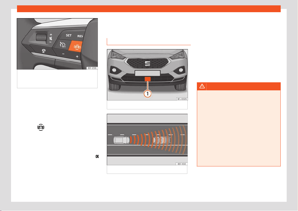
Assistant systems
179
Drive assist sensors and cameras
Fig.130 L
eft side of the multifunction steering
wheel: button for driver assistance systems
(depending on the version).
Depending on the equipment, the button for the
driv
er assistance systems is located on the turn
signal and main beam lever or on the multifunc-
tion steering wheel. This button can be used
to switch the driver assistance systems in the
Assistants menu on and o.
●
Press the
button to open the Assis-
tants menu.
●
Select the assistance system in question and
t
urn it o or on. A mark indicates that assistant
system is switched on.
●
Next, confirm the selection by pressing the
button on the multifunction steering wheel.
The assist
ant systems can also be switched on
and o in the infotainment system, in the vehi-
cle settings menu ›››page37.
Drive assist sensors and
camer
as
Front radar
Fig.131 On the fr
ont bumper: radar sensor.
Fig.132 Det
ection area.
A radar sensor may be fitt
ed to the front
bumper of the vehicle ›››Fig.131. The front
radar detects any objects in its detection zone
›››Fig.132 and provides support for the follow-
ing functions:
●
Front Assist ›››page193.
●
Adaptive Cruise Control (ACC) ›››page185.
The r
adar can have a range of up to 120m
(400ft) depending on road and weather condi-
tions.
WARNING
●
The visibility of the radar sensor can be
impair
ed by dirt or environmental influences
such as rain, fog, snow, mud, dust, insects
etc. In this case the Front Assist and ACC
functions may stop working. The instrument
panel displays the following message: No
sensor vision! And the Front Assist un-
available or ACC unavailable warning lights
come on.
●
Clean the sensor area on the bumper as
indicat
ed in ›››page368, Cleaning the ex-
terior. When the radar sensor starts correctly
detecting again, the message disappears
from the screen and the functions become
available again.
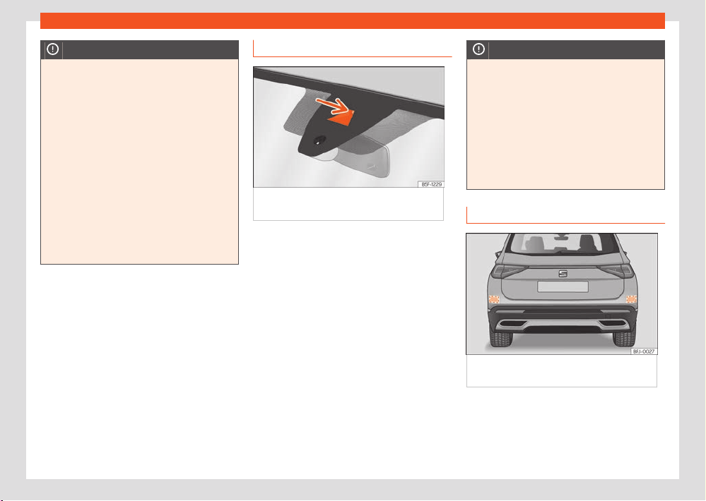
180
Assistant systems
NOTICE
●
If the radar sensor is dirty or poorly adjus-
t
ed, the Front Assist system may give unnec-
essary warnings and apply the brakes inap-
propriately.
●
The operation of the radar can be aected
by strong reflections of the emitted signal.
This may occur, for example, in an enclosed
car park or due to the presence of metallic
objects (e.g. guard rails or sheets used in
road works).
●
The sensor may not be adjusted correctly
if it receives an impact. This may compro-
mise the system's ecacy or disconnect it. If
you have the feeling that the radar sensor is
damaged or adjusted incorrectly, switch o
the Front Assist and ACC functions to avoid
any damage. If this occurs have it adjusted.
Front camera
Fig.133 On the windscr
een: field of vision of
the Lane Assist system camera.
Depending on the equipment, the vehicle may
be fitt
ed with a front camera on the front wind-
screen. This camera detects lane boundaries
(lines) to provide support for the following func-
tions:
●
Lane Assist ›››page196.
●
Travel Assist ›››page198.
●
Emergency assist ›››page201.
NOTICE
To avoid aecting the oper
ation of the sys-
tems, take the following points into consider-
ation:
●
Clean the field of vision of the camera reg-
ularly and make sure it is free of snow and
ice.
●
Do not cover the field of vision of the cam-
era.
●
Check that the windscreen is not damaged
in the area of the camera's field of vision.
Rear radar
Fig.134 R
ear view of the vehicle: radar sensor
areas.
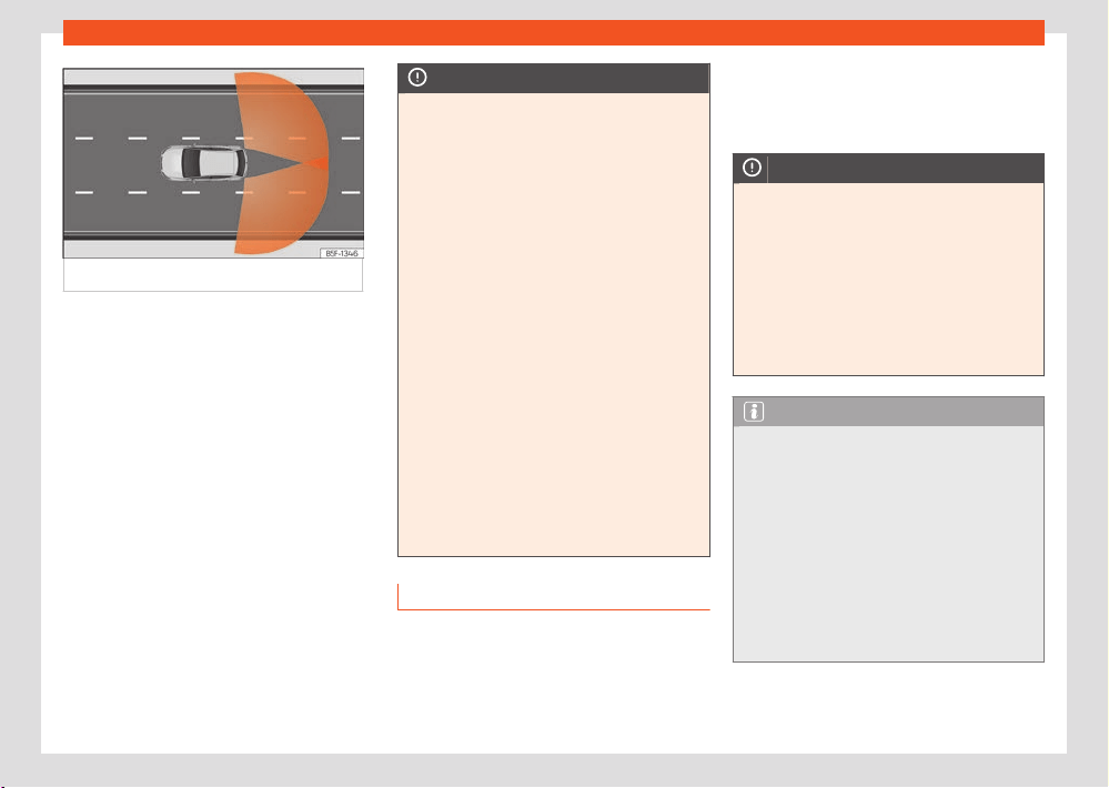
Assistant systems
181
Drive assist sensors and cameras
Fig.135 Sensor det
ection zones.
The radar sensors are located on the left and
right of the bumper and ar
e not visible from the
outside ›››Fig.134. The sensors monitor both
the blind spot and trac behind the vehicle
›››Fig.135.
They support the following functions:
●
Lane departure warning (Side Assist)
›››page202.
●
Rear cross trac alert (RCTA) ›››page233.
Automatic deactivation of supported func-
tions
The rear radar sensors deactivate automati-
cally when, among other reasons, one of the
sensors is detected to be permanently covered.
This may be the case if, for example, there is a
layer of snow or ice over one of the sensors.
The relevant text message will appear in the
instrument panel display.
NOTICE
●
The radar sensors on the rear bumper may
be damaged or shift
ed in the event of a colli-
sion, for example, when entering or exiting a
parking space. This may result in the system
disconnecting itself, or at least possibly hav-
ing its functionality diminished.
●
In order to ensure that the radar sensors
work properly, keep the rear bumper free of
snow and ice and do not cover it.
●
The rear bumper should only be painted
with paint authorised by SEAT. The lane de-
parture warning's functions may be limited or
work incorrectly if other paints are used.
●
The visibility of radar sensors may be af-
fected due to leaves, snow, strong haze or
dirt, among others. Clean the area in front of
the sensors.
●
Never use auto lane changing or the rear
cross trac alert if the radar sensors are
dirty.
●
Radar operation may also be aected if
objects such as bicycle racks or luggage
racks interfere with the visibility of the ra-
dars.
Ultrasound sensors
The bumpers are fitted with ultrasound sensors
to perform the following functions:
●
Park Assist ›››page2
16.
●
Park assist plus ›››page210.
●
Rear park assist ›››page214.
NOTICE
●
Damage to the radiator grille, bumper,
wheel ar
ch and vehicle underbody can mod-
ify the orientation of the sensors. This can af-
fect the parking aid function. Have the func-
tion checked by a specialised workshop.
●
A number plate or number plate holder
with dimensions that exceed the space for
the number plate, or a cured or deformed
number plate can cause false detections or a
loss of visibility for the sensors.
Note
●
In order to guarantee good operation, keep
the sensors cl
ean, free of snow and ice, and
do not cover them with stickers or other ob-
jects.
●
If you use high-pressure or vapour equip-
ment for cleaning, do not apply it directly,
unless you do so very briefly, and always
keep a distance of more than 10 cm away.
●
Fitting certain accessories to the front of
the vehicle, such as a plate holder with ad-
vertising, may interfere with the operation of
the Park Assist.
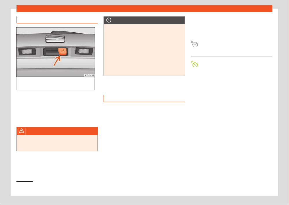
182
Assistant systems
1)
Valid for hybrid vehicles.
Area View system
Fig.136 On the r
ear lid handle: top view
system.
Depending on your vehicle’s equipment, it can
be fitt
ed with 1 or 4 cameras that provide sup-
port to the following functions:
●
Top View Camera ›››page226.
●
Rear View Camera ›››page223.
WARNING
Fitting a number plate frame may interfere
with the vie
w shown on the screen, as it may
reduce the camera’s field of vision.
NOTICE
●
In order to guarantee good system opera-
tion, k
eep the cameras clean, free of snow
or ice, and do not cover them with stickers
or other objects. The camera can be cleaned
by operating the wiper.
●
Never use abrasive cleaning products to
clean the camera lens.
●
Do not use hot or warm water to remove
ice or snow from the camera lens. Doing so
could damage the camera.
Cruise control system
Introduction
The cruise control system (GRA) helps maintain
a constant speed set by you.
Speed range
The cruise control system is available when
driving in forward gear at a speed of over ap-
prox. 20km/h (15mph).
Temporarily switching o the cruise control
The saved speed can be exceeded at any time,
e.g. for overtaking. The cruise control is suspen-
ded during acceleration and is then resumed
with the saved speed.
Status display
When the cruise control system is switched on,
the instrument cluster display shows the saved
speed and the system status:
It lights up grey.
The cruise control system is switched on,
but regulation is not active.
It lights up green.
The cruise control system is switched on
and regulation is active.
If there is no speed saved, the instrument clus-
ter display shows ––– instead of speed.
Changing gears
As soon as the clutch pedal is depressed, regu-
lation is suspended and resumes once the gear
change has been made.
Driving down slopes
1)
Shift into a low gear before descending a long
hill. This makes use of engine braking and re-
lieves the brakes.
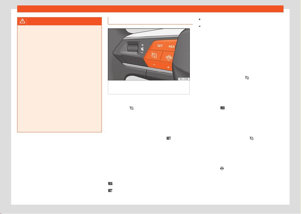
Assistant systems
183
Cruise control system
WARNING
If it is impossible to drive with sucient br
ak-
ing distance and at a constant speed, using
the cruise control system may cause acci-
dents and serious injuries may occur.
●
Do not use Travel Assist when visibility is
bad, on steep roads, on windy roads or in
slippery circumstances (such as snow, ice,
rain or loose gravel), or on flooded roads.
●
Only use the cruise control system on
paved roads with a firm surface.
●
Adapt your speed and safety distance to
the vehicle in front of you at all times to suit
the visibility, weather, road and trac condi-
tions.
●
After use, always switch o the speed lim-
iter to prevent the speed being regulated
against your wishes.
●
It is dangerous to use a set speed which
is too high for the prevailing road, trac or
weather conditions.
Operating the cruise control
Fig.137 On the multifunction st
eering wheel:
cruise control operation buttons.
Connecting
●
Press the
button.
Ther
e is no speed saved and regulation is not
yet operating.
Start regulation
●
While driving, press the button
.
The cruise contr
ol system saves and regulates
the current speed.
Adjusting the speed
While the GRA is set, the stored speed can be
adjusted:
+ 1 km/h (1mph)
- 1 km/h (1mph)
+ 10 km/h (5mph)
- 10 km/h (5mph)
The cruise contr
ol system only operates the ac-
celeration, it does not brake the vehicle.
In hybrid vehicles the cruise control system
changes the current speed by accelerating or
braking.
Interrupting the adjustment
●
Briefly press the button
or press the brake
pedal.
The speed is st
ored.
Reinstating the cruise control
●
Press the
button.
The cruise contr
ol system resumes the saved
speed and regulates it.
Switching o
●
Press and hold the button
.
The cruise contr
ol system switches o and the
saved speed is deleted.
Switching o the speed limiter
●
Press the
button.
●
Select the speed limiter on the instrument
clust
er display.
The cruise control system is switched o.
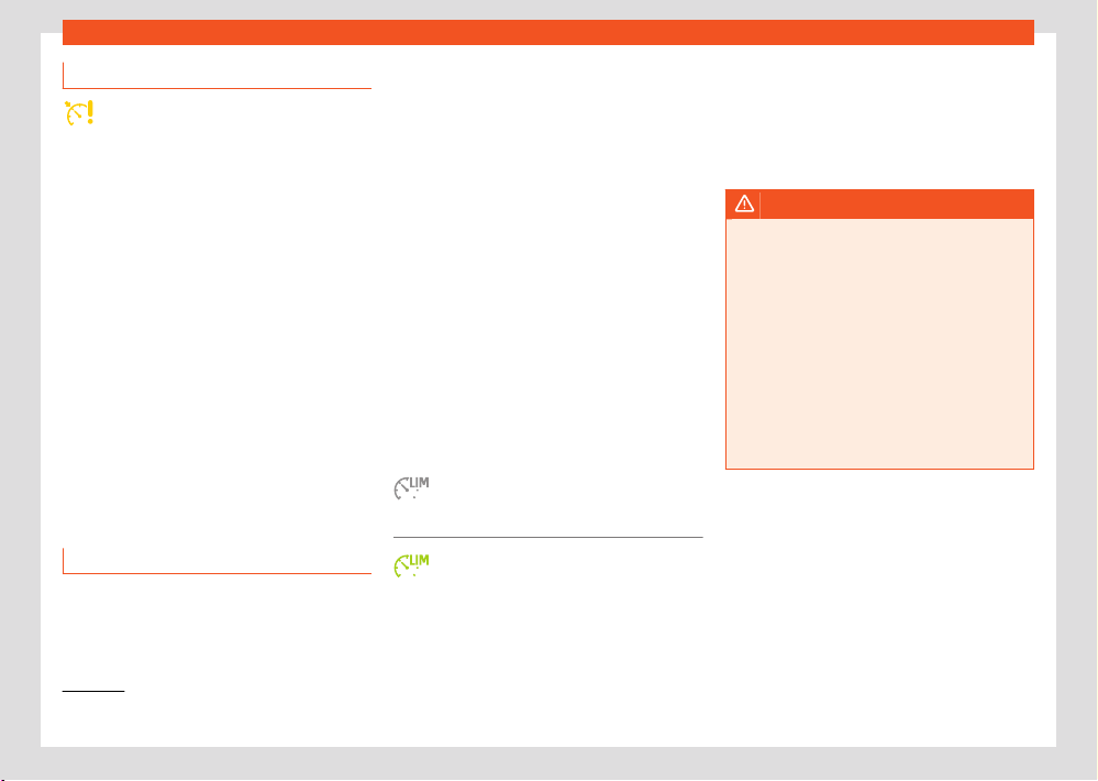
184
Assistant systems
1)
Valid for hybrid vehicles.
Troubleshooting
Cruise control fault
The contr
ol lamp switches on yellow.
Abnormal operation. Switch o the cruise con-
trol system and take the vehicle to a specialist
workshop.
The adjustment is interrupted unexpectedly
●
If the clutch pedal is pressed for a long time.
●
The vehicle has exceeded the saved speed
for a long time.
●
No forward gear has been selected.
●
A brake assistance system has intervened,
e.g. TCS or ESC.
●
Front Assist has braked the vehicle.
●
If the fault continues, disconnect the Emer-
gency Assist and consult a specialised work-
shop.
Speed limiter
Introduction
The speed limited helps the driver not to ex-
ceed a set speed.
Speed range
The speed limiter helps avoid exceeding a pro-
grammed speed, from 30km/h (20mph) ap-
prox. and faster.
By selecting the speed limiter
The speed limitation can be interrupted at any
time by depressing the accelerator pedal fully,
beyond the point of resistance. As soon as the
saved speed is exceeded, the green indicator
light flashes and an audible warning signal may
sound. The speed is stored.
The limiter is reactivated automatically after re-
turning to less than the set speed.
Status display
When the speed limiter is switched on, the
instrument cluster display shows the saved
speed and the system status:
It lights up grey
The speed limiter is switched on but reg-
ulation is not active.
Lights up green
The speed limiter is switched on and ac-
tive.
Driving down slopes
1)
Shift int
o a low gear before descending a long
hill. This makes use of engine braking and re-
lieves the brakes.
WARNING
After use, always switch o the speed limit
er
to prevent the speed being regulated against
your wishes.
●
The speed limiter does not relieve the
driver of their responsibility to drive at the
appropriate speed. Do not drive at high
speed if not necessary.
●
Using the speed limiter under adverse
weather conditions is dangerous and can
cause serious accidents, e.g. aquaplaning,
snow, ice, leaves, etc. Only use the speed
limiter when the status of the road and the
weather conditions allow it.
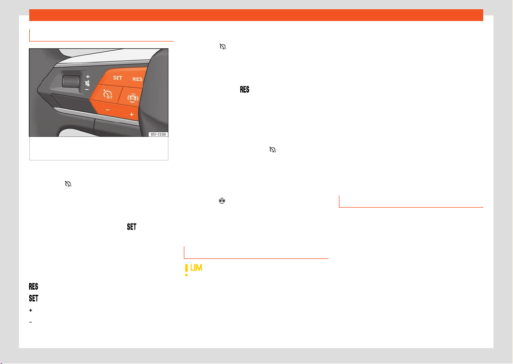
Assistant systems
185
ACC - Adaptive Cruise Control
Operating the speed limiter
Fig.138 On the multifunction st
eering wheel:
buttons to control the speed limiter.
Connecting
●
Press the
button.
It does not t
ake eect yet.
Start regulation
●
While driving, press the button
.
The curr
ent speed is saved as a limit speed.
Adjusting the speed
The programmed speed can be set:
+ 1 km/h (1mph)
- 1 km/h (1mph)
+ 10 km/h (5mph)
- 10 km/h (5mph)
Interrupting the adjustment
●
Press the
button.
The speed is st
ored.
Reinstating the cruise control
●
Press the button
.
The limit
er will re-activate as soon as the vehi-
cle is moving at a speed lower than the saved
one.
Switching o
●
Press and hold the button
.
The speed limit
er switches o and the speed is
deleted.
Switch to another driver assistance system
●
Press the
button.
●
Observe the corresponding message on the
instrument clust
er display. The speed limiter is
switched o.
Troubleshooting
The speed limiter is not available
The control lamp switches on yellow.
●
Malfunctions Switch o the speed limit
er and
go to a specialist workshop.
The adjustment is interrupted unexpectedly
●
You have switched o the El
ectronic Stabiliza-
tion Control (ESC).
●
The brakes have overheated. Wait for the
brakes to cool down and check the operation
again.
●
If the fault continues, consult a specialised
workshop.
For safety reasons, the speed limiter only
switches o fully whenever the driver stops
pressing the accelerator pedal or switches the
system o manually.
ACC - Adaptive Cruise Con-
trol
Introduction
Adaptive Cruise Control (ACC) maintains a
constant speed set by the driver. When ap-
proaching another vehicle in front, the ACC de-
tects it and adapts the speed automatically,
maintaining a distance set by the driver.
Does my vehicle have ACC?
Your vehicle has ACC if it has the ACC func-
tion buttons on the multifunction steering wheel
›››page105, or if it has the configuration menu
in the infotainment system.
186
Assistant systems
Speed range
ACC r
egulates at speeds between 30 and
210km/h (20 and 130mph).
When E-Mode is activated in hybrid vehicles,
the ACC speed range may vary.
If the vehicle is fitted with an automatic gear-
box, the ACC can bring the vehicle to a stand-
still if a vehicle in front of it stops.
If your vehicle is fitted with a manual gearbox,
you must pay attention to speed and gear
changes. The ACC is deactivated if the speed is
too low (less than 30 km/h) of the engine RPM
is too low or high.
Driving with ACC
You can override the ACC at any time. Braking
interrupts the ACC. If you accelerate, regulation
is interrupted during acceleration and then re-
sumed.
Driver intervention prompt
ACC is subject to certain limitations inher-
ent to the system. This means that the
driver will have to control the speed and
distance from other vehicles in certain sit-
uations. In this case, the instrument cluster
display will tell you to intervene by ap-
plying the brake, and an audio warning will
be played.
Radar sensors
The ACC uses the front radar technology. Read
its maintenance instructions and information
about its limitations ›››page178.
WARNING
The ACC’s technology cannot overcome the
syst
em's inherent limitations or change the
laws of physics. If used negligently or invol-
untarily, it may cause serious accidents and
injuries. The system is not a replacement for
driver awareness.
●
Always be prepared to brake or accelerate.
●
If you press the accelerator pedal the ACC
will stop working. Therefore, it will not brake
or request any braking intervention.
●
Adapt your speed and safe distance to the
vehicle in front of you at all times to suit visi-
bility, weather, road and trac conditions.
●
Do not use the ACC in poor visibility, or on
roads that are steep, with lots of curves or
slippery.
●
Never use ACC when driving o-road or on
unpaved roads.
●
The system does not react in time to sta-
tionary obstacles (such as a trac jam
queue). React soon enough to avoid a haz-
ardous situation.
●
The system does not react to people, an-
imals or vehicles that are crossing or ap-
proaching in the opposite direction.
●
If you are driving with a spare wheel fitted,
the ACC system could automatically switch
o. Switch o the system when starting o.
●
Brake immediately if the ACC does not
slow down enough.
●
Brake immediately when a driver interven-
tion instruction is displayed on the instru-
ment cluster screen.
●
If the vehicle continues to move involuntar-
ily after a driver intervention prompt, brake
the vehicle.
Note
If the ACC does not work as described in
this chapt
er, do not use it until it has been
checked by a specialised workshop. Visiting
a SEAT dealership is recommended.
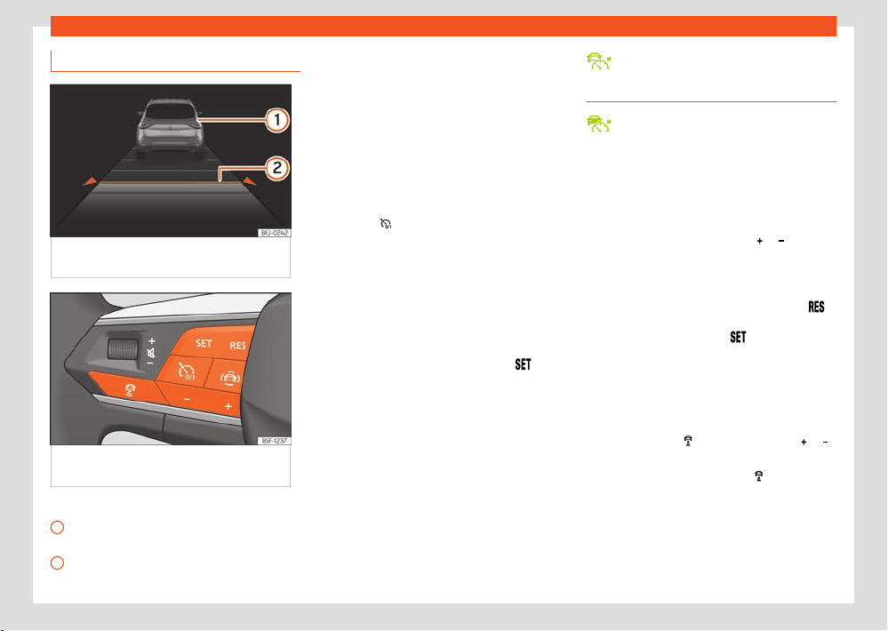
Assistant systems
187
ACC - Adaptive Cruise Control
1
2
ACC operation
Fig.139 On the instrument panel displ
ay: ACC
active.
Fig.140 On the multifunction st
eering wheel:
buttons for operating the ACC.
›››Fig.139
Vehicle ahead detected. It will light up if the
dist
ance to the vehicle is adjusted.
Selected distance level 2.
This information can be displayed on the cen-
tr
al panel of the Assistants view, or in the left
hand information profile ›››page16. If these
views are not selected, it will be automatically
displayed in the lower central part of the instru-
ment cluster in a simplified manner.
The set speed will be displayed next to the
function status indicator.
Connecting
●
Press the
button on the multifunction
st
eering wheel ›››Fig.140.
The ACC does not regulate anything yet
(standby).
Start regulation
Activating the ACC system also automatically
activates the ESC and traction control (TCS).
●
To start regulation, press the button
›››Fig.140.
The ACC sets the curr
ent speed, or the closest
speed within the valid range (30-210 km/h), as
the cruise speed.
Vehicles with automatic transmission: the gear
lever must be in the D, S or M.
With manual transmission: the gear lever must
be in any gear except first and reverse, and the
speed must be higher than approximately 30
km/h (18 mph).
Depending on the driving situation, the follow-
ing indicator lamps come on:
Lights up green
ACC connected, no vehicle detected in
front.
Lights up green
ACC connected, vehicle detected in
front.
When the ACC is in standby, the indicator
lamps light up grey.
Setting speed
To program the speed, press the
or
›››Fig.140 butt
ons to the desired speed. The
speed is adjusted at intervals of 10 km/h (5
mph).
While the ACC is active, you can press the
button to increase the desired speed by 1 km/h
(
1 mph). You can then press
to decrease it
by 1 km/h (
1 mph).
Setting your distance level
The distance can be set to one of five levels,
from very short to very long:
●
Press the button
and then the button or
›››Fig.140.
●
Alternatively, press the button as many
times as necessary t
o set the desired distance.
Keep in mind each country’s regulations on
minimum braking distances.
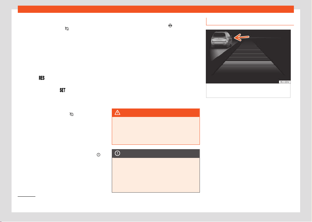
188
Assistant systems
1)
Or on the left, in countries that drive on the left hand side of the road.
Suspend regulation (standby)
●
Briefly pr
ess the button
›››Fig.140 or
pr
ess the brake pedal.
The ACC indicator lamp is grey; the speed and
distance are saved.
If the ESC or TCS is switched o, the ACC is
automatically interrupted.
Reinstating the cruise control
●
Press the
button. The ACC regulates to
the l
ast speed and distance setting.
●
OR: Press the button
to regulate to the
curr
ent speed.
Switching o
●
Press and hold the button
. The set speed is
cl
eared.
Exceeding the speed regulated by the ACC
While driving with the ACC switched on, the
driver can increase speed by pressing the ac-
celerator pedal. ACC regulation is suspended
until you release the accelerator pedal ›››
.
Set the def
ault distance setting
In the Infotainment system, you can pre-select
the distance level when connecting the ACC
from:
●
Very short, Short, Medium, Long and Very long
using the Infotainment system:
Driver assis-
t
ance > ACC ›››page37.
Changing the driving profile
In vehicles with the SEAT Drive Profile, the se-
lected driving profile can have an influence on
the ACC’s acceleration and braking behaviour
›››page170.
In vehicles without SEAT Drive Profile, the be-
haviour of the ACC can also be aected if any
of the following drive profiles are selected in
the infotainment system in Drive assist. ACC
settings will be the same as those in the SEAT
Drive Profile.
WARNING
Before driving o, check that the r
oad is
clear. The radar sensor may not detect ob-
stacles on the road. This could cause an ac-
cident and serious injuries. If necessary, ap-
ply the brake.
NOTICE
If you increase speed using the accelerator
pedal, the ACC may not be abl
e to safely
adjust the speed of the distance due to the
limitations of the system.
●
Be prepared to react if required by the sit-
uation.
Special driving situations
Fig.141 On the instrument panel displ
ay: ACC
active, vehicle detected on the left.
Be aware of the limitations and warnings
described at the beginning of this chapt
er
›››page185, Introduction.
Avoid undertaking on the right
1)
If a vehicle is detected in the left lane that is
travelling at a speed slower than that set by the
driver, it will brake the vehicle within the comfort
limits of the system to avoid passing it on the
right ›››Fig.141.
You can cancel this regulation by changing the
set speed or by pressing the accelerator pedal.
The function works at speeds over 80km/h
(50mph). It may not be available in certain
countries.
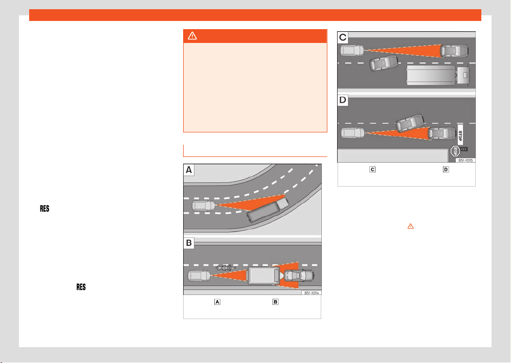
Assistant systems
189
ACC - Adaptive Cruise Control
Overtaking
When the t
urn signal is switched on for over-
taking, the ACC reduces the distance from the
vehicle in front to help with the overtaking ma-
noeuvre. The set cruising speed will not be ex-
ceeded.
The function works at speeds over 80km/h
(50mph). It may not be available in certain
countries.
Stop&Go function
Valid for vehicles with an automatic gearbox
The ACC can bring the vehicle to a standstill if
the vehicle in front stops.
The ACC remains active and the message ACC
ready to start is displayed on the instru-
ment cluster for a few seconds. You can extend
or reactivate this warning by pressing the but-
ton
or by grabbing the wheel if your vehicle
is fitt
ed with Travel Assist. During this time, the
vehicle will move o again if the vehicle in front
moves forwards.
To move o when the message ACC ready to
start is not longer displayed, once the vehicle
in front has moved o:
●
Press the accelerator pedal.
●
OR: pr
ess the
button on the multifunction
st
eering wheel.
The ACC is deactivated in the following cases:
●
The stopping phase lasts for several minutes.
●
When a vehicle door is opened.
WARNING
If the message ACC ready to start is
displ
ayed on the instrument cluster display
and the vehicle in front moves o, your vehi-
cle will move o automatically. In this case,
any obstacles in the road may not be detec-
ted. This may cause serious accidents and
injuries.
●
Always check the road before moving o,
and apply the vehicle brakes yourself if nec-
essary.
ACC system limitations
Fig.142 Vehicle on a bend. Motorcyclist
ahead, out of r
ange of the radar sensor.
Fig.143 Vehicle changing lanes. One
v
ehicle turning and another stationary.
The limits of the ACC system mean that it is not
appr
opriate in all situations.
SEAT does not recommend using the function in
the following cases ›››
:
●
Heavy rain, snow or fog.
●
When going through tunnels.
●
In sections with roadworks.
●
On routes with curves, e.g. on mountain roads.
●
On o-r
oad routes.
●
In covered car parks.
●
On roads with embedded metal objects such
as train or tram tracks.
●
On roads with loose gravel.
190
Assistant systems
Pay special attention when using ACC in the
f
ollowing situations:
On curves
The ACC may not detect the vehicle in front
on a curve, or may regulate the distance from
vehicles in other lanes ›››Fig.142
.
V
ehicles outside the sensor zone
In the following situations the ACC may not re-
act, or may react slowly or inappropriately:
●
Vehicles that are not aligned while driving or
that are outside the sensor's detection area,
such as motorcycles ›››Fig.142
.
●
Vehicles that move into your lane, a short dis-
t
ance from your vehicle ›››Fig.143
.
●
Vehicles with loads or accessories that pro-
trude fr
om the sides, rear or roof.
Objects that are not detected
The ACC function only detects and reacts to
vehicles moving in the same direction. There-
fore it does not detect:
●
People
●
Animals
●
Vehicles travelling in the opposite direction or
crossing the road.
●
Other stationary obstacles
The ACC does not react to stationary vehicles.
If, for example, a vehicle detected by the ACC
turns or moves over and there is a stationary
vehicle in front of it, the ACC will not react to
the second vehicle ›››Fig.143
.
WARNING
Using the ACC in the above situations can
cause serious accidents and injuries, and
you coul
d break the law.
Troubleshooting
ACC not available
The indicator lamp lights up yellow:
●
The radar sensor is dirty or adjusted in-
corr
ectly. Take into account the warnings
described at the beginning of this chapter
›››page179
●
There is a fault or a defect. Turn o the vehi-
cle's ignition and turn it on again after a few
minutes.
●
If the problem persists, consult a specialised
workshop.
The ACC does not work as expected
●
Make sure that the conditions are met for the
r
adar sensor to operate properly ›››page179.
●
If the brakes overheat, regulation stops au-
tomatically. Wait for them to cool down and
check the operation again.
●
Unusual noises during automatic ACC brak-
ing are normal and do not indicate any anoma-
lies.
The following conditions may lead the ACC
not to react:
●
The accelerator or brake is depressed.
●
No gear is engaged or the vehicle is in gear R.
●
The vehicle is reversing.
●
ESC is operating.
●
The driver is not wearing his/her seat belt.
●
The RPM is too high or too low.
●
A vehicle brake light is faulty.
●
A trailer brake light is faulty.
●
The parking brake is applied.
●
Driving on an excessive slope.
Assistant systems
191
Predictive speed adjustment
Predictive speed adjust-
ment
Intr
oduction
The predictive speed adjustment adapts the
speed to the speed limitations detected and
to the road layout (curves, crossings, round-
abouts, etc.).
Predictive speed adjustment is an additional
function of the ACC ›››page185 and uses the
trac signal detection system ›››page27 and
the navigation data of the infotainment system.
Predictive speed adjustment is available de-
pending on the equipment, although not in all
countries.
WARNING
The predictive speed adjustment smart tech-
nology cannot overcome the limits imposed
by the laws of physics and it only works
within the limits of the system. Never allow
the enhanced convenience of this function
induce you to take any risk that compromises
safety. If used negligently or involuntarily,
it may cause serious accidents and injuries.
The system is not a replacement for driver
awareness.
●
Always adapt your speed to suit visibility,
weather, road and trac conditions.
●
Always pay attention to trac and always
keep the vehicle environment in mind.
●
Always be prepared to adjust the speed
yourself
. If the trac sign recognition sys-
tem is not working properly or the navigation
data is not updated, the speed may change
unexpectedly and suddenly or may not be
suitable for the current trac situation. In
addition, the speed adjusted by the system
may not suit your driving style.
●
Always be prepared to adjust the speed
yourself. If you drive without any active gui-
ded route, if you leave the route calculated
by the navigation system or if the position of
the vehicle cannot be determined correctly
because the GPS does not provide accurate
data, the speed may change unexpectedly
and suddenly or may not adapt to the cur-
rent trac situation.
●
Always use up to date navigation data.
●
Always take into account the maximum
permitted speed. In the case of speed limita-
tions that are not included in the navigation
data, the maximum permitted speed may be
exceeded.
Note
Also note the information related to the ACC
r
elevant to safety ›››page185.
Limitations of the predictive speed
adjustment
In addition to the limitations of the road sign de-
tection system ›››page27 and the limitations
of the ACC, predictive speed adjustment has
the following limitations inherent to the system:
●
Predictive speed adjustment only recognises
trac signals that show a speed limitation. The
predictive speed adjustment does not take into
account, above all, the rules on priority of pas-
sage or trac lights.
●
Trac signs that indirectly show a speed re-
striction, e.g. signs at the entrance to towns,
are only recognised on the basis of navigation
data.
●
On roads that are not included in the naviga-
tion dat
a, or that are included with little accu-
racy, predictive speed adjustment is not availa-
ble.
●
If a speed limitation is notified based on the
navigation data without it being detected by
the trac signal detection system, the indica-
ted speed will be adjusted to the speed that
was saved the last time.
●
Predictive speed adjustment is not available
for speed limitations below approx. 20 km/h
(approx. 15 mph). In this case, a relevant mes-
sage is displayed on the instrument panel
screen.
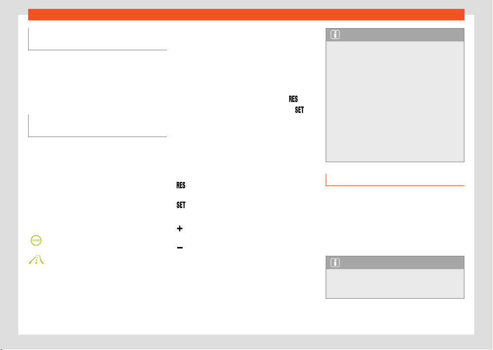
192
Assistant systems
Activating the predictive speed ad-
justment
In the inf
otainment system, in the assist services
menu, you can individually adjust the type of
incident the vehicle should react to ›››page37:
●
Response to road layout.
●
Response at permitted speeds.
Driving with the predictive speed ad-
justment
●
Connect the ACC ›››page187.
●
Set the distance and speed.
●
Activate the predictive speed adjustment.
As soon as the syst
em recognises a speed limi-
tation or a relevant road layout during the route,
a warning will appear on the instrument panel
display. This warning will indicate the reason
and the speed to which the vehicle will adjust
due to said limitation.
Adjustment due to a speed limitation.
Adjustment due to a road layout.
In the event of adjustment due to a speed lim-
itation, the detected speed will be saved as
the new desired speed. In the event of adjust-
ment due to the road layout, the vehicle will
accelerate again after leaving the reason for
the adjustment behind and the speed will be
adjustment t
o that which has been saved.
The speeds indicated for curves depend on the
driving profile›››page170.
Interrupting speed adjustment
●
During the warning, press the button
.
●
During the regulation, press the button .
Adjust the announced speed
The announced speed can only be adjust
ed in
the event of adjustment due to a speed limita-
tion.
Multifunction steering wheel:
+ 1 km/h (1 mph), only while the ACC is
adjusting
- 1 km/h (1 mph), only while the ACC is ad-
justing
+ 10 km/h (5mph)
- 10 km/h (5mph)
If you adjust the indicated speed excessively,
the pr
edictive speed adjustment is interrupted.
Note
●
When a speed limitation is recognised, the
pr
edictive speed adjustment also adapts the
saved speed even if the ACC is switched o.
However, it will not adjust.
●
If the speed of travel considerably exceeds
the speed limit det
ected by the trac signal
detection system, a relevant warning is dis-
played in the instrument panel display.
●
In the event of joining a highway without
speed limitation, the recommended speed is
automatically saved as the desired speed. If
a higher speed has previously been saved for
a motorway without a speed limit, this is used
instead of the recommended speed.
Troubleshooting
A message is displayed indicating that pre-
dictive speed adjustment is not currently
available or not in your country.
●
If this message is displayed for a long time
and predictive speed adjustment is available in
your country, contact a specialised workshop.
Note
Depending on the anomaly in question, ad-
ditional inf
ormation may be displayed in Ve-
hicle status ›››page36.
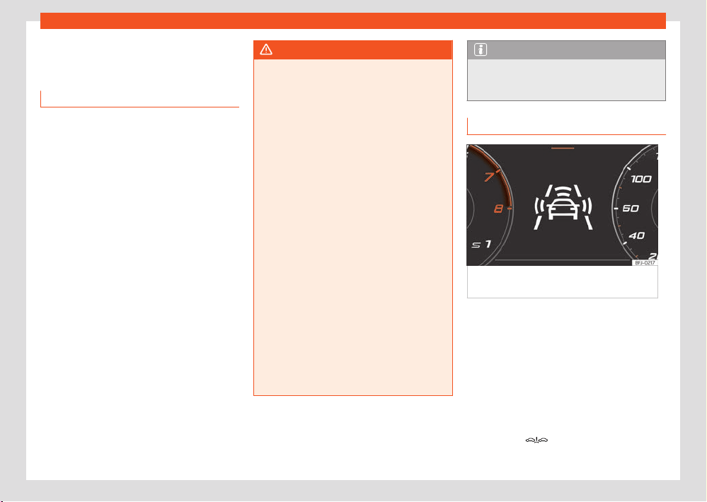
Assistant systems
193
emergency brake assistance system (Front Assist)
emergency brake assis-
t
ance system (Front Assist)
Introduction
The objective of the system is to prevent head-
on collisions against objects that may be in the
vehicle’s path or minimise the consequences of
such impacts.
The function is designed to avoid collisions
against:
●
Parked vehicles.
●
Vehicles, pedestrians and cyclists that are
tr
avelling in the same lane and direction.
●
Pedestrians and cyclists who transversely
cross the vehicle path.
Front Assist detects the aforementioned objects
using a radar sensor at the front of the vehicle
›››page179.
Depending on several factors and how critical
the situation is, the system operates in a stag-
gered manner.
First informing the driver, and if there is no or
insucient reaction, then activating an autono-
mous emergency braking as indicated by the
conditions that will be discussed in the follow-
ing points.
The system operation can be cancelled if the
clutch pedal is pressed or the steering wheel is
turned firmly.
WARNING
●
Front Assist is a driving assistance function
that can ne
ver replace the driver’s attention.
●
Front Assist cannot change the laws of
physics or replace the driver in terms of
keeping control of the vehicle and reacting
to a possible emergency situation.
●
Following a Front Assist emergency warn-
ing, pay immediate attention to the situation
and try to avoid the collision where appropri-
ate.
●
Always adapt your speed and distance
away from the vehicle in front of you at
all times to suit visibility, weather, road and
trac conditions.
●
The Front Assist alone cannot avoid acci-
dents and serious injuries.
●
The Front Assist does not react to animals
or vehicles crossing your path or approach-
ing head-on down the same lane.
●
The Front Assist does not react to pedes-
trians walking head-on in the same lane.
●
If the Front Assist does not work as descri-
bed in this chapter (e.g. it repeatedly inter-
venes unnecessarily), switch it o. Have the
system checked by a specialised workshop.
SEAT recommends visiting a SEAT dealer-
ship.
Note
When Front Assist is connected, the indica-
tions of other functions on the scr
een may be
hidden.
Warning levels and brake assist
Fig.144 On the instrument panel displ
ay:
advance warning indications.
Front Assist is active from 5km/h (3mph). De-
pending on dier
ent conditions (vehicle speed,
speed and type of object recognised, etc.),
some of the stages described below are omit-
ted to optimise the performance of the system.
Safety distance warning
If the system detects that you are driving too
close to the vehicle in front, it will warn the
driver with this indication on the instrument
panel display
.
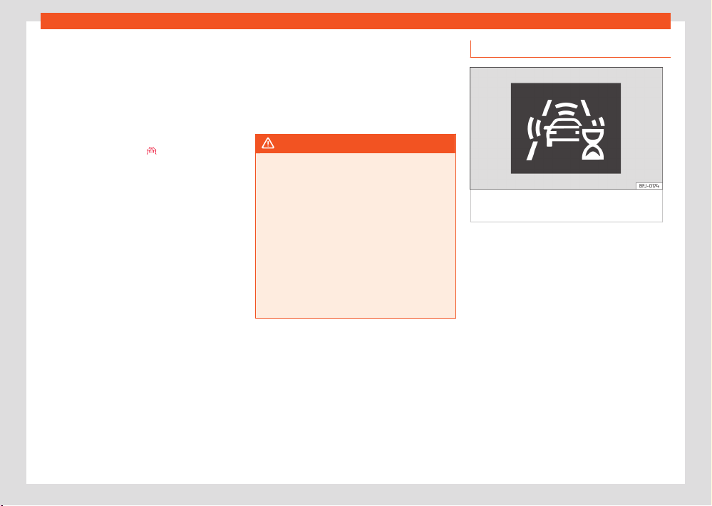
194
Assistant systems
The timing of the warning varies depending
on driv
er behaviour, vehicle speed and relative
speed between both.
Advance warning
If the system detects a possible collision with
the vehicle in front, it alerts the driver by means
of an audible warning and an indication on the
instrument panel display
›››Fig.144.
The w
arning moment varies depending on the
trac situation and driver behaviour. At the
same time, the vehicle will prepare for a possi-
ble emergency braking ›››page194.
When Front Assist is connected, the indications
of other functions on the screen may be hidden.
Critical warning
If the driver fails to react to the advance warn-
ing, the system may actively intervene in the
brakes and generate a brief jolt to warn the
driver of the imminent danger of a collision.
Automatic braking
If the driver also fails to react to the critical
warning, the system may initiate independent
emergency braking by progressively increasing
the braking in accordance with the criticality of
the situation.
Driver emergency braking assistance sys-
tem
If the driver, after the critical warning, starts
braking but the system detects that the brake
is not being applied with sucient force, the
braking intensity will be increased.
WARNING
●
The system cannot prevent a collision, al-
though it can significantly minimise the con-
sequences by r
educing the speed and the
force of the impact.
●
When the Front Assist causes a braking, the
brake pedal is “harder”.
●
Automatic interventions by the Front Assist
on the brakes may be interrupted by pressing
the clutch, accelerator or moving the wheel.
●
The Front Assist may brake the vehicle until
it stops completely. However, the brake sys-
tem does not halt the vehicle permanently.
Use the foot brake!
System limitations
Fig.145 On the instrument clust
er screen:
indication of the system’s initial self-calibration.
Front Assist has certain limitations inherent to
the syst
em. Thus, in certain circumstances,
some of the reactions may be inappropriate
from the driver's standpoint. So pay attention
in order to intervene if necessary.
The following conditions may cause the
Front Assist not to react or to do so too late:
●
In the first few instants of driving after switch-
ing on the ignition, due to the system’s initial
auto-calibration. During this period, a status
icon ›››Fig.145 is displayed.
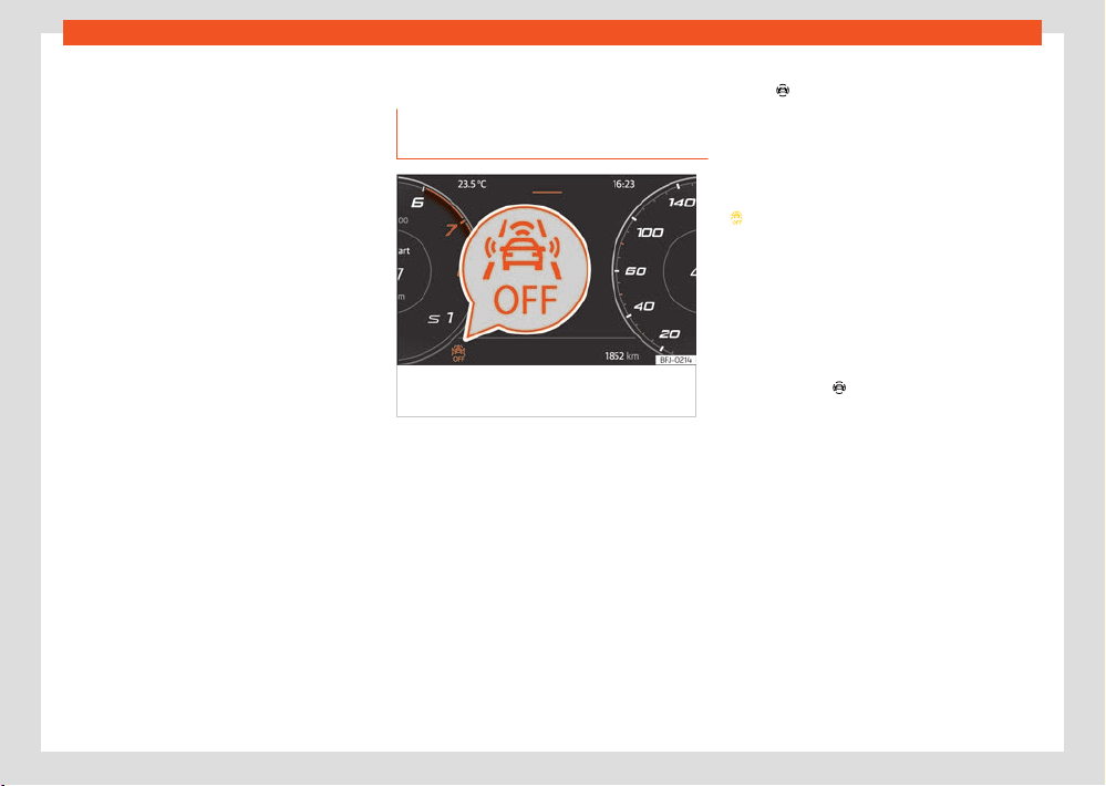
Assistant systems
195
emergency brake assistance system (Front Assist)
Unrecognised objects
●
Loads and accessories of other vehicles that
pr
otrude over the sides, backwards or over the
top.
●
If there are metal objects, e.g. guard rails or
sheets used in road works.
●
Other vehicles crossing the vehicle’s path.
●
Misaligned vehicles.
●
Narrow vehicles such as motorcycles.
●
Vehicles approaching in the opposite direc-
tion.
Operating limitations
●
If the radar sensor is disabled or faulty.
●
If the radar sensor is dirty or covered.
●
On taking tight bends or complex paths.
●
When pressing the accelerator firmly or at full
throttle.
●
If the TCS has been disconnected or the ESC
is activated in Sport mode ›››page175.
●
If the ESC is adjusting or is broken.
●
If several brake lights of the vehicle or electri-
cally connected trailer are damaged.
●
If the vehicle is reversing.
●
In case of snow or heavy rain.
●
In complex driving situations (such as trac
islands, cut-through roundabouts, etc), Front
Assist may issue warnings and intervene in
braking in an unnecessary manner.
For more details, see section ›››page178.
Manual activation and deactivation
of the function
Fig.146 On the scr
een of the instrument panel
Front Assist switched o message.
The Front Assist is active whenever the ignition
is s
witched on.
When the Front Assist is disabled, so too are
the advance warning and the distance warning
functions. SEAT recommends leaving the Front
Assist activated except in the situations presen-
ted in ›››page196.
Switching the Front Assist on and o
With the ignition switched on, the Front Assist
can be deactivated or activated as follows:
●
In the infotainment system: press the function
butt
on
Driver assistance > Front Assist
›››page37.
●
OR: Sel
ect the corresponding menu option
using the button for the assistants systems
›››page178.
When Front Assist is deactivated, the indication
will be displayed on the instrument cluster.
Each time the ignition is s
witched on, the Front
Assist will reappear as active.
Activating or deactivating the pre-warning
(advance warning)
The advance warning can be activated or de-
activated in the infotainment system using the
function button
Driver assistance > Front
Assist ›››page37.
The syst
em will store the setting for the next
time the ignition is switched on.
SEAT recommends keeping advance warning
active.
Depending on the vehicle’s infotainment system
the advance warning function may be adap-
ted in the following modes:
●
Advance
●
Medium
●
Delayed
●
Deactivated
SEAT recommends driving with the function in
“Medium” mode.
196
Assistant systems
Switching distance warning on and o
The dist
ance warning can be activated or de-
activated in the infotainment system using the
function button
Driver assistance > Front
Assist ›››page37.
The syst
em will store the setting for the next
time the ignition is switched on.
SEAT recommends keeping the distance warn-
ing active.
Deactivating Front Assist temporarily in the
following situations
In the following situations the Front Assist should
be deactivated due to the system's limitations:
●
When the vehicle is to be towed.
●
If the vehicle is on a test bed.
●
When the radar sensor is damaged.
●
If the radar sensor receives a violent impact.
●
If it intervenes several times unnecessarily.
●
If the radar sensor is temporarily covered by
an accessory.
●
When the vehicle is going to be loaded onto
transportation.
Lane Assist system
Introduction
The Lane Assist System helps the driver stay
in his/her lane within the physical limits of the
system. This function is not suitable and is not
designed to keep the vehicle automatically in
the lane.
Using the camera located in the windscreen,
the Lane Assist system detects the lane boun-
daries dividing the lanes in which the vehicle
is travelling. If the vehicle gets too close to
the detected lane limits, the system alerts the
driver through a corrective motion of the steer-
ing wheel. The driver can cancel the steering
corrective action at any time.
No warning is produced with the turn signals
activated, given that the Lane Assist system un-
derstands that a lane change is required.
System limits
Use the Lane Assist system only on large, well-
maintained motorways and highways.
The system is not available under the following
conditions:
●
The driving speed allowed is below approx.
55 km/h (30 mph).
●
The system has not detected any lane lines.
●
On tight bends.
●
Temporarily in very sporty driving situations.
●
If the turn signal is switched on before a man-
ual l
ane change.
●
If the driver firmly rectifies a system interven-
tion.
●
If a lane marking is crossed despite system
intervention.
●
If the driver does not react to a request to
intervene.
WARNING
The intelligent technology in the Lane Assist
syst
em cannot change the limits imposed by
the laws of physics and by the very nature of
the system. Careless or uncontrolled use of
the Lane Assist system may cause accidents
and injury. The system is not a replacement
for driver awareness or manoeuvres when
driving.
●
Always adapt your speed and the distance
to the vehicles ahead in line with visibility,
weather conditions, the condition of the road
and the trac situation.
●
Always keep your hands on the steering
wheel so it can be turned at any time. The
responsibility of staying in the lane is always
the driver's.
●
The Lane Assist system does not detect
all road markings. The road surfaces, road
structures or objects in poor condition can
be incorrectly detected as road markings un-
der certain circumstances by the Lane Assist
system. Immediately counter any unwanted
intervention of the system.
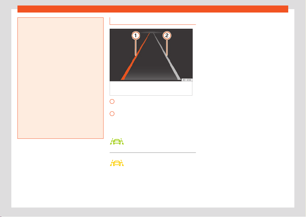
Assistant systems
197
Lane Assist system
1
2
●
Please observe the indications on the in-
strument panel and act as is necessary if the
tr
ac situation permits.
●
In the following situations there may be
undesired interventions of the system or it
may be that the system does not intervene
at all. In these situations, special attention is
required from the driver and, where appropri-
ate, the temporary deactivation of the lane
assist warning system:
–
In very sporty driving situations.
–
In adverse weather conditions and roads
in poor condition.
–
When passing through areas undergoing
works.
–
Before gradient changes of grade and
river beds.
●
Always observe the vehicle surroundings
carefully and drive proactively.
●
When the area of vision of the camera
becomes dirty, covered or is damaged, the
Lane Assist system function can be aected.
Driving with the Lane Assist System
Fig.147 On the instrument clust
er screen:
indications of the lane assist system.
Yellow line: The system intervenes assisting
on the r
epresented side.
White line: Lane line detected. The system
does not intervene.
Control lamps
Lights up green
Lane Assist system active and availa-
ble.
Lights up yellow
The Lane Assist system intervening
with a rectification of the steering.
Switching the lane assist system on or o
In some countries, the Lane Assist System is al-
ways activated when the ignition is switched on.
The connection status is shown in the Driver
assistance menu of the Inf
otainment system or
the driver assistance systems menu after press-
ing the corresponding button. These menus can
be used to activate and deactivate the system.
The Lane Assist system is designed to actively
intervene as of approximately 60 km/h (35
mph) and if it has detected the lane boundaries
(system status: active).
If the control lamp of the instrument cluster dis-
play is o, it means that the system is connec-
ted but not ready to intervene or it is disconnec-
ted.
When you activate a turn signal, the system
temporarily goes into a passive state in order to
allow manual lane change.
An energetic rotation or rectification of the
steering wheel by the driver causes the system
to temporarily switch to a passive state.
Driver intervention prompt
If the steering is not corrected manually, the
system prompts the driver through an indication
on the instrument panel display and acoustic
warnings.
If no reaction is obtained from the driver, the
system switches to a passive state.
Regardless of the steering manoeuvres,
through an indication on the instrument panel
display and acoustic warnings, the driver is also
prompted to drive through the centre of the
lane if the steering correction lasts more than
reasonable.
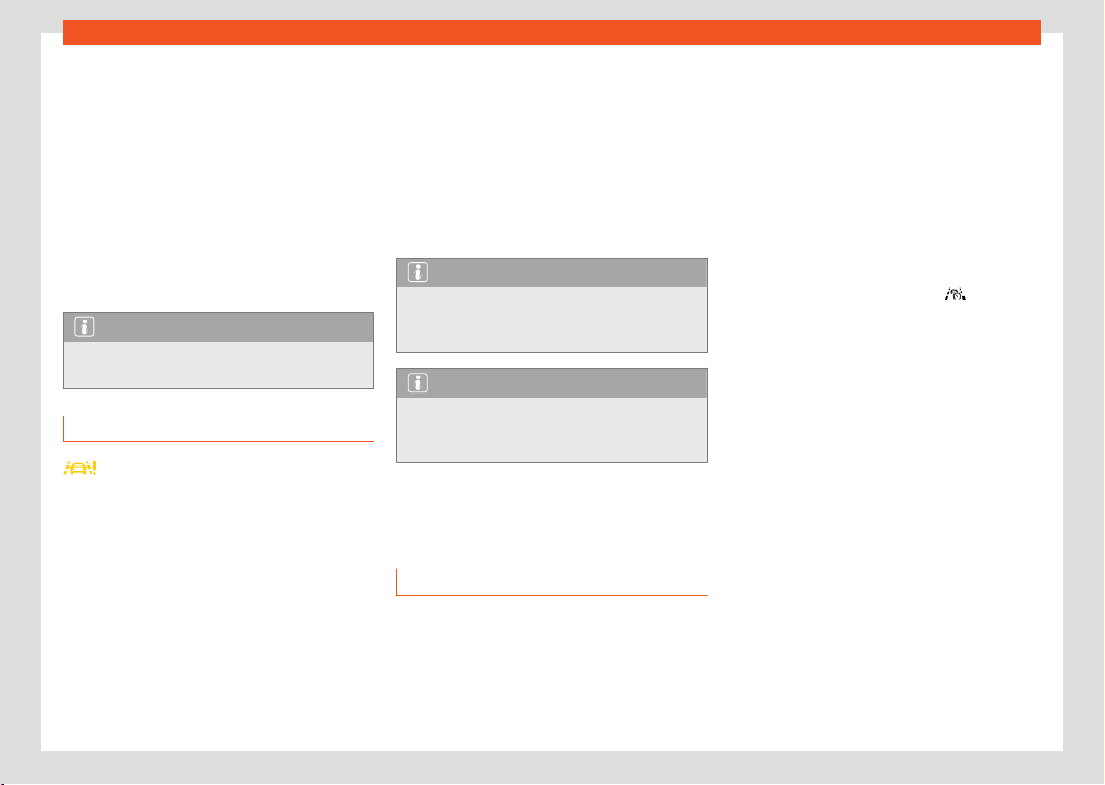
198
Assistant systems
Steering wheel vibration
The f
ollowing situations may result in a steering
wheel vibration:
●
The lane ceases to be recognised during a
sudden intervention in the direction of the sys-
tem.
It is also possible to select steering wheel vibra-
tion in the Assistants menu of the infotainment
system. In this case, when a vehicle with Lane
Assist switched on crosses over a detected lane
marking, the steering wheel will vibrate.
Note
If the lane departure warning assistant is
f
aulty, it may switch o automatically.
Troubleshooting
Lane Assist is not available
The contr
ol lamp switches on yellow. A relevant
warning is also displayed on the instrument
panel screen.
●
The fiel
d of vision of the camera is dirty.
Clean the windscreen ›››page367.
●
The visibility of the camera is diminished due
to accessories or adhesives.
●
There is a fault or a defect. Switch the engine
o and on again.
The system behaves dierently than expec-
ted
●
The camera has been altered or damaged,
e.g. because of damage caused to the wind-
screen. Check for visible damage.
●
Do not mount objects on the steering wheel.
If the problem persists, consult a specialised
workshop.
Note
After switching on the ignition, it may take a
f
ew seconds before a fault is detected in the
system.
Note
If Lane Assist is unavailable, Emergency As-
sist and T
ravel Assist will be unavailable as
well.
Driving Assist (Travel As-
sist)
Introduction
Travel Assist combines adaptive cruise control
(ACC) and the adaptive lane guidance func-
tion. Within the limitations of the system, the ve-
hicle can maintain a distance from the vehicle
in front that is preselected by the driver and
remain in the preferred position within the lane.
Travel Assist uses the same sensors as Adap-
tiv
e Cruise Control (ACC) and Lane Assist.
Therefore, carefully read the information about
the ACC ›››page185 and the Lane Assist
›››page196 and take into account the limita-
tions of the systems and the indications given in
the information.
How to know if the vehicle is fitted with
Travel Assist
The vehicle is fitted with Travel Assist if the mul-
tifunction steering wheel has the
button.
Speed r
ange
Depending on the type of gear, Travel Assist
regulates from 0km/h (0mph). The speed can
be set from 30km/h (20mph).
Driving with Travel Assist
Travel Assist automatically controls the accel-
erator pedal, the brakes and the steering. In
addition, Travel Assist may, within its limitations,
decelerate the vehicle until it stops behind an-
other that stops and automatically starts again.
You can override assisted adjustment at all
times.
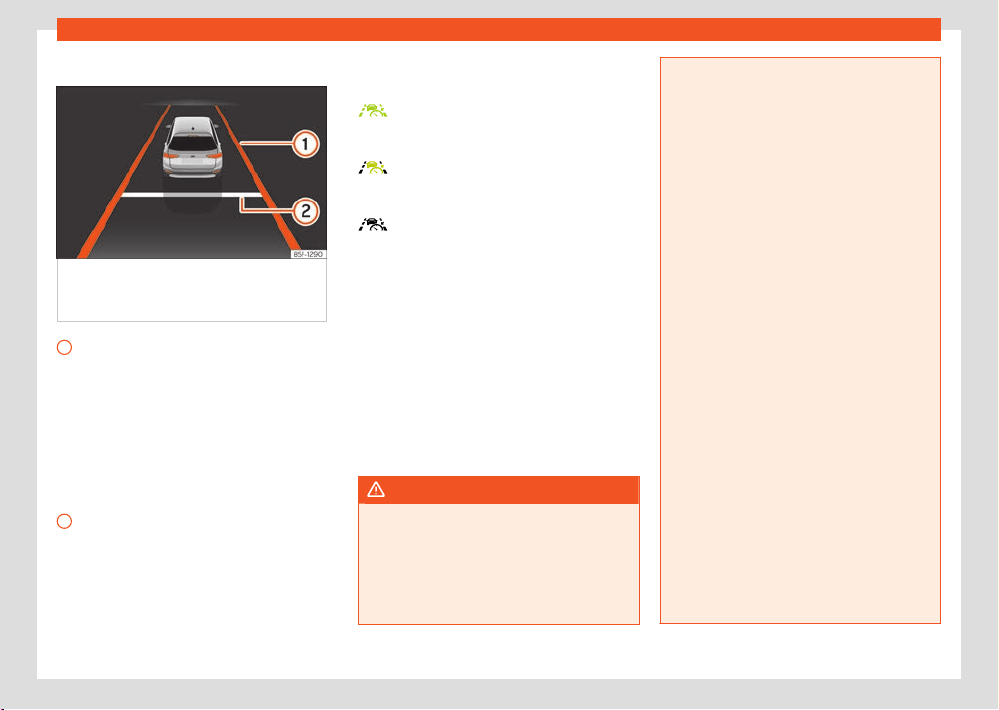
Assistant systems
199
Driving Assist (Travel Assist)
Status display
Fig.148 On the instrument clust
er display:
display of active regulation (schematic
representation).
1
The colour of the lane markings indicates
the st
atus of the adaptive lane guidance
function.
●
Yellow: adaptive lane guidance function
active.
●
White: adaptive guidance function avail-
able.
●
Grey: passive adaptive lane guidance
function.
2
Distance set.
Depending on the equipment, additional de-
t
ails, e. g. dashed road markings and vehicles
in front, can also be shown on the instrument
cluster display.
Control lamps indicate the status of the system
on the instrument panel displ
ay:
Travel Assist active, adaptive cruise con-
trol and adaptive lane guidance function
are active.
Travel Assist active, adaptive cruise con-
trol active and adaptive lane guidance
function passive.
Travel Assist deactivated, not regulating.
Driver intervention prompt
If you r
emove your hands from the steering
wheel, after a few seconds the system asks
you to take over the steering with an indication
on the instrument panel display and acoustic
warnings.
If you do not react, Travel Assist is deactivated.
Depending on the equipment, Emergency As-
sist activates if it is activated in the infotainment
system.
WARNING
The Travel Assist smart technology cannot
o
vercome the limits imposed by the laws of
physics and it only works within the limits
of the system. If Travel assist is used negli-
gently or involuntarily, it may cause serious
accidents and injuries. The system is not a
replacement for driver awareness.
●
Bear in mind the system limitations and
the indications r
egarding the control of the
Adaptive Cruise Control (ACC) and Lane As-
sist.
●
Adapt your speed and safety distance to
the v
ehicle in front of you at all times to
suit visibility, weather, road and trac condi-
tions.
●
Do not use Travel Assist when visibility is
bad, on steep roads, on windy roads or in
slippery circumstances (e. g., snow, ice, rain
or loose gravel), or on flooded roads.
●
Do not use Travel Assist oroad or on roads
where the surface is not firm. Travel Assist
has been designed for use on paved roads
only.
●
Travel Assist does not react to people or
animal or vehicles crossing your path or
which approach you head-on in the same
lane.
●
Brake immediately if Travel Assist does not
slow down enough.
●
Brake immediately when instructed to do
so on the instrument cluster display, or if
Travel Assist does not reduce speed su-
ciently.
●
Brake when the vehicle continues to move
forward without it being desired after an indi-
cation to brake.
●
If possible, do not wear gloves while driv-
ing. The syst
em could interpret this as no
driving activity.
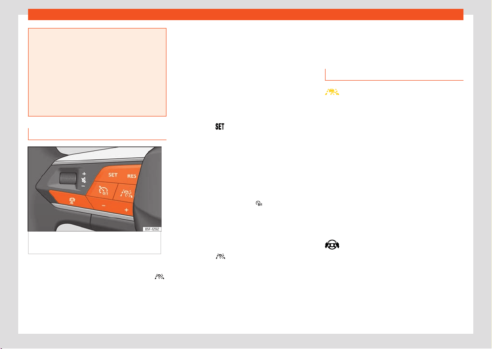
200
Assistant systems
●
If driver intervention is requested on the in-
strument panel displ
ay, immediately resume
control of the vehicle.
●
Keep your hands on the steering wheel at
all times, to ensure you have control over the
steering at all times. The driver is always re-
sponsible for keeping the vehicle in its own
lane.
●
Always be prepared to adjust the speed
yourself.
Operating Travel Assist
Fig.149 L
eft side of the multifunction steering
wheel
Switch on and start regulation
1. While driving with ACC activated, press
on the multifunction steering wheel.
The v
ehicle switches from ACC to Travel As-
sist.
Depending on the driving situation, the vehicle
s
witches to the following system statuses in
Travel Assist:
●
When ACC is regulating, Travel Assist main-
tains the current speed and the preset distance
to the vehicle in front.
When lane markings are detected, the vehicle is
also kept in the lane by steering movements.
●
If ACC is not regulating, Travel Assist remains
selected but in a passive (unregulated) status.
1. Press the
button.
T
ravel Assist switches to the active system
status, depending on the driving situation.
The indicator lamp for the driving situation
lights up on the instrument cluster display. A
message is also displayed.
Interrupting the adjustment
1. Briefly press the button
.
OR: pr
ess the brake pedal.
The set distance remains saved.
Switch to ACC
1. Press the
button on the multi-function
st
eering wheel.
The vehicle switches from Travel Assist to
the ACC system status corresponding to
the driving situation.
Making other adjustments
All other aspects of Travel Assist are controlled
like the ACC.
Troubleshooting
Travel Assist is not available or does
not w
ork as expected
The control lamp switches on yellow. A relevant
warning is also displayed on the instrument
panel screen.
●
There is a fault in the sensors. Check the cau-
ses and solutions described in the inf
ormation
about the ACC ›››page190 or Lane Assist
›››page198.
●
There is a fault or a defect. Switch the engine
o and on again.
●
The system limits are exceeded.
●
If the problem persists, consult a specialised
workshop. SEAT recommends visiting a SEAT
dealership.
Grip the steering wheel
The w
arning lamp lights up white, and a mes-
sage is shown on the instrument cluster display.
●
You released the steering wheel for a few sec-
onds. T
ake hold of the steering wheel and take
control of the vehicle.
Assistant systems
201
Emergency Assist
Grip the steering wheel
The w
arning lamp lights up red and a mes-
sage is shown on the instrument cluster display.
Depending on the situation, an audio warning
sounds or the steering wheel vibrates.
●
You have let go of the steering wheel for
a long time, or the system limits have been
reached. Immediately take hold of the steering
wheel and take control of the vehicle.
Travel Assist disconnects automatically
●
Vehicles without Emergency Assist:
You have released the steering wheel for a long
period.
●
There is a fault or a defect. Switch the engine
o and on again.
●
If the problem persists, consult a specialised
w
orkshop. SEAT recommends visiting a SEAT
dealership.
The adjustment is interrupted unexpectedly
●
You have turned on the turn signal.
Emergency Assist
How it works
Emergency Assist can detect whether there is
inactivity by the driver and can automatically
keep the car in its lane and stop it altogether
if necessary. This way the system can actively
help av
oid an accident or reduce its conse-
quences.
Emergency Assist uses the same sensors as
Adaptive Cruise Control (ACC) and Lane As-
sist. Therefore, carefully read the information
about the ACC ›››page185 and Lane Assist
›››page196 and take into account the limita-
tions of the systems and the indications given in
the information.
Driver intervention prompt
If the emergency assist detects that the driver is
not actively doing anything, he or she is promp-
ted to take control of the vehicle by audio
warnings and a brief application of the brake. In
addition, a warning is shown on the instrument
cluster display and the volume of the infotain-
ment system is lowered.
Depending on the equipment, the driver’s seat
belt is tightened at the same time.
System intervention
If the driver does not react, the system can
brake the vehicle and keep it in its lane. The fol-
lowing control lamp lights up on the instrument
cluster display:
The system is regulating.
You can cancel the adjustment at any time by
moving the steering wheel, over-accelerating
or braking.
While the emergency assistant is in operation,
other road users are warned as follows:
●
The hazard warning lights are switched on
soon after.
●
The horn sounds (depending on the speed).
The following happens as soon as the vehicle
stops:
●
The electronic parking brake is activated.
●
All doors are unlocked.
●
The interior lighting comes on.
●
Depending on the features, an emergency
call (eCall) is made.
Connecting and disconnecting
Emergency Assist can be switched on and o in
the assistants menu of the infotainment system.
When connected, the Emergency Assist is only
activated if the following requirements are met:
●
The Travel Assist or the Lane Assist are
switched on.
●
The system has detected a road lane mark-
ing on both sides of the vehicle.
Note
If the emergency assist is faulty, it may
s
witch o automatically.
Note
If Lane Assist is unavailable, Emergency As-
sist will be unav
ailable as well.
202
Assistant systems
WARNING
The smart technology fitt
ed into the Emer-
gency Assist cannot overcome the limits im-
posed by the laws of physics; it only works
within the limits of the system. The driver is
responsible for driving the vehicle.
●
Adapt your speed and safety distance to
the vehicle in front of you at all times to suit
the visibility, weather, road and trac condi-
tions.
●
The Emergency Assist cannot always avoid
accidents or serious injuries by itself.
●
If the radar sensor or the camera are cov-
ered or have been altered or damaged, the
system may intervene on the brakes or on the
direction in an inappropriate manner.
●
The Emergency Assist does not react to
people or animal or vehicles crossing your
path or which approach you head-on in the
same lane.
WARNING
If the Emergency Assist Intervenes inoppor-
t
unely, serious accidents and injuries may
occur.
●
If the vehicle behaves dierently than
expected, interrupt the intervention of the
Emergency Assist by over-accelerating,
braking or moving the steering wheel.
●
Do not use Travel Assist or Lane Assist.
Have the system checked by a specialised
workshop.
Troubleshooting
Emergency Assist not available
The control lamp switches on yellow. A relevant
w
arning is also displayed on the instrument
panel screen.
●
The field of vision of the camera is dirty.
Clean the windscreen.
●
The visibility of the camera is diminished due
to weather factors, e.g. snow, or detergent resi-
due or some coating. Clean the windscreen.
●
The visibility of the camera is diminished due
to accessories or adhesives. Leave the area
around the camera’s field of vision free.
●
The camera has been altered or damaged,
e.g. because of damage caused to the wind-
screen. Check for visible damage.
●
There is a fault or a defect. Switch the engine
o and on again.
●
If the fault continues, disconnect the Emer-
gency Assist and consult a specialised work-
shop.
Lane departure warning
(Side Assist)
Introduction
The lane departure warning uses radar sen-
sors to monitor the areas behind the vehicle
›››page6. The system does this by measuring
the vehicle's distance from other vehicles and
its speed dierential. The lane departure warn-
ing will not work at speeds of less than approx.
15km/h (9mph).
The lane width is not detected individually, but
is rather pre-configured in the system. Thus if
you are driving in wide lanes or in between two
lanes, the indications may be incorrect. Further-
more, the system can detect vehicles driving in
the lane next to you (if there are any), and can
also detect stationary objects such as dividers,
and thus give an incorrect indication.
Trailer mode
Side assist is automatically deactivated and
cannot be switched on if the factory-fitted tow-
bar is electrically connected to a trailer or simi-
lar device.
As soon as the driver starts to drive with a trailer
connected electrically to the vehicle, a mes-
sage is displayed on the instrument panel dis-
play indicating that side assist is switched o.
Once the vehicle trailer has been disengaged,
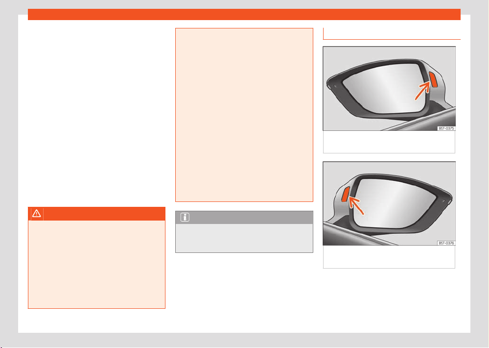
Assistant systems
203
Lane departure warning (Side Assist)
side assist will return to the initial state prior to
the moment the tr
ailer was electrically connec-
ted.
If the tow-bar is not factory fitted, side assist
should be switched o manually when driving
with a trailer.
Physical limitations inherent to the system
In some situations the lane departure warning
may not interpret the trac situation correctly.
I.e. in the following situations:
●
on tight bends;
●
in the case of lanes with dierent widths;
●
in areas with significant gradient changes;
●
in adverse weather conditions;
●
in the case of special constructions to the
side of the vehicle, e.g., high or irregular divid-
ers.
WARNING
The smart technology incorporated into Side
Assist cannot o
vercome the limits imposed
by the laws of physics; it only works within
the limits of the system. Accidents and se-
vere injury may occur if Side Assist is used
negligently or involuntarily. The system is not
a replacement for driver awareness.
●
Adapt your speed and safe distance to the
vehicle in front of you at all times to suit visi-
bility, weather, road and trac conditions.
●
Keep your hands on the wheel at all times
to be ready to intervene in the steering at any
time.
●
Pay attention to the indicator lamps that
may come on in the external rear view mir-
rors and on the instrument cluster, and follow
any instructions they may give.
●
The lane departure warning could react
to any special constructions that might be
present to the sides of the vehicle, e.g. high
or irregular dividers. This may cause errone-
ous warnings.
●
Never use the lane departure warning on
unpaved roads. The lane departure warning
has been designed for use on paved roads.
●
Always pay attention to the vehicle's sur-
roundings.
●
The control lamps of the lane departure
warning may have limited functionality due
to solar radiation.
Note
If Side Assist does not work as described in
this chapt
er, stop using it and contact a spe-
cialised workshop.
Driving with Side Assist
Fig.150 Contr
ol lamp of the lane departure
warning.
Fig.151 Contr
ol lamp of the lane departure
warning.
Connecting and disconnecting
Side Assist can be s
witched on and o by
accessing the Assistants menu of the infotain-
ment system or through the instrument clus-
ter display using the controls on the steering

204
Assistant systems
wheel. If the vehicle is equipped with a multi-
function camer
a, it can also be accessed by
means of the assistants systems key located on
the main beam headlight lever.
When the lane departure warning is ready to
operate, the indications in the control lamps will
turn on briefly as confirmation.
When the vehicle is restarted, the last adjust-
ment in the system will remain active.
Indication on the exterior mirror
The control lamp provides an indication on the
corresponding side regarding the trac situa-
tion behind the vehicle, if it is deemed to be
critical. The control lamp on the left-hand side
indicates the trac situation to the rear left of
the vehicle, and the control lamp on the right-
hand side indicates the trac situation to the
rear right of the vehicle .
In the case of retrofitted tinted windows or win-
dows with tinted film, the indications of the ex-
ternal mirrors may not be seen clearly.
Keep the external mirrors clean and free of
snow and ice, and do not cover them with ad-
hesives or other similar materials.
It lights up
It turns on once briefly: the lane departure warning
is activated and ready to operate, i.e. when acti-
vating the system.
It lights up
It lights up continuously: the lane departure warn-
ing has detected a vehicle in the blind spot.
Flashes
A vehicle has been detected in the adjacent lane
and the turn signal has been engaged in the direc-
tion of the detected vehicle.
For vehicles that are also equipped with Lane As-
sist ›››page196, a warning to switch lanes will
also appear even though the turn signal has not
been engaged (Lane Assist “Plus”).
The control lamps light up when the ignition is
switched on and should turn o after approxi-
mately 2 seconds. This is the time taken for the
function check.
If there are no indications from the control lamp
of the lane departure warning, this means that
the lane departure warning has not detected
any other vehicles at the rear area.
When the exterior lighting is low, the intensity
with which the control lamps come on is dim-
med. The user can modify the intensity of the
control lamps with up to 5 levels in the infotain-
ment system menu.
Lane assist Plus.
The Lane Assist Plus function can be used by
activating the Lane Assist ›››page196 and
Side Assist functions. In this case its functions
are expanded as described below.
If the driver initiates a lane change manoeuvre
in a potential critical situation:
●
The lamp flashes in the corresponding rear-
view mirror even though the turn signal has not
been activated.
●
The steering wheel vibrates to warn the driver
of the risk of collision.
●
torque is applied to correct the steering and
return the vehicle to its lane.
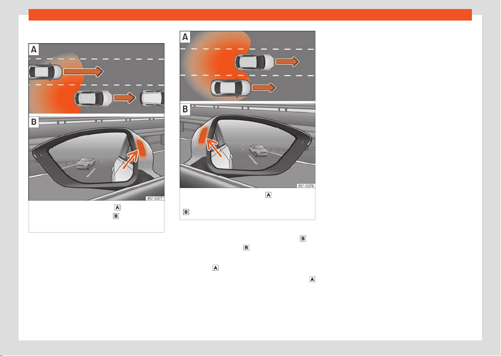
Assistant systems
205
Lane departure warning (Side Assist)
Driving situations
Fig.152 Schematic diagr
am:
Overtaking
with tr
ac behind the vehicle.
Side Assist
indication on the l
eft hand side.
Fig.153 Schematic diagr
am:
Overtaking in
the centr
al lane and then joining the right lane.
Side Assist indication on the right hand side.
In the following situations, an indication will be
displ
ayed in the control lamp ›››Fig.152
(arrow) or ›››Fig.153 (arrow):
●
When being overtaken by another vehicle
›››Fig.152 .
●
When passing another vehicle ›››Fig.153
with a speed dier
ential of approx. 10 km/h (6
mph). If the vehicle is passing at a considerably
higher speed, no indication will be displayed.
The faster the vehicle approaches, the sooner
an indication will be displayed in the control
lamp, because the lane departure warning
takes into account the speed dierential with
other vehicles. Thus even though the distance
from the other vehicle is identical, the indication
will appear sooner in some cases and later in
others.
206
Parking and manoeuvring
Parking and manoeu-
vring
P
ark the vehicle
Parking
When parking your vehicle, all legal require-
ments should be observed.
1. Connect the electronic parking brake
›››page207.
2. Automatic transmission: mo
ve the selector
lever to position P.
3. Stop the engine and turn o the ignition.
T
urn the steering wheel slightly to engage
the steering lock.
4. Manual gearbox: engage first gear on flat
ground and slopes, or even reverse gear on
hills, and release the clutch pedal.
5. On slopes, turn the steering wheel so that if
the parked vehicle were to start moving, it
would steer toward the kerb.
6. Exit the vehicle ›››
. Watch out for other
r
oad users!
7. Take all vehicle keys with you and lock it.
To avoid damage or hazardous situations, al-
ways park the vehicle on a suitable parking sur-
face ›››
.
WARNING
If the vehicle is parked incorrectly, it could
r
oll away, even on gentle slopes. This can
cause accidents and serious injuries.
●
When parking, always carry out the opera-
tions in the stipulated order.
●
Before leaving the vehicle, make sure that
the electronic parking brake is engaged.
WARNING
If children, people who may need assistance
or animal
s are left unattended in the vehicle,
accidents and serious injuries can occur.
●
Never leave children, people who may
need assistance or animals unattended in
the vehicle. They could operate the gear
selector and release the electronic parking
brake. The vehicle could be set in motion.
●
Never leave children, people who may
need assistance, or animals in the vehicle.
Depending on the season, very high or low
temperatures can be reached inside a closed
vehicle.
●
Always take all vehicle keys with you when
leaving the vehicle.
NOTICE
The presence of irregularities on the ground,
sand or mud can cause damage t
o the vehi-
cle and mean that it cannot be parked prop-
erly.
●
Always park the vehicle on firm and flat
ground.
NOTICE
Components on the underside of the vehicle,
such as bumpers, spoil
ers and running gear
components, can be damaged when running
over objects protruding from the ground.
●
Drive carefully when entering buildings, on
ramps, driving over kerbs or fixed markings,
and on descents.
NOTICE
Avoid parking the vehicle where the hot ex-
haust syst
em could ignite inflammable mate-
rials, such as dry grass, low bushes, spilt fuel
or flammable materials.
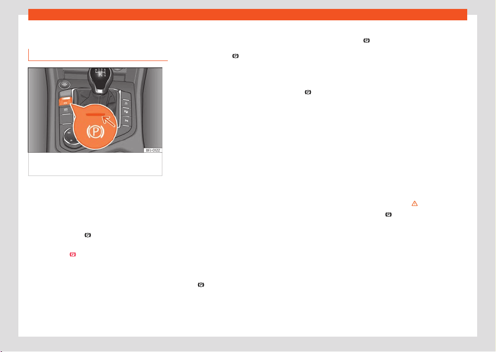
Parking and manoeuvring
207
Electronic parking brake
Electronic parking brake
Using the el
ectronic parking brake
Fig.154 Centr
e console, lower part: electronic
parking brake button.
Connecting
The el
ectronic parking brake can be activated
whenever the vehicle is at a standstill, even
when the ignition is switched o. Activate it
whenever you leave or park the vehicle.
●
Pull and holdthe ›››Fig.154 button.
The parking brake is on when the red indicator
lamp turns on on the instrument cluster and
the button indicator lamp turns on.
●
Release the button.
Switching o
●
Switch the ignition on.
●
Press the button ›››Fig.154. At the same
time st
ep hard on the brake pedal or, if the
engine is running, press the accelerator pedal
slightly.
●
The indicator lamp on button and the red
indicator lamp on the instrument cluster turn
o.
Aut
omatic disconnection when moving o
The electronic parking brake automatically dis-
connects when moving o in any of the follow-
ing situations, if the driver's door is closed and
the driver's seatbelt is buckled:
●
Vehicles with automatic gearboxes: a gear is
engaged or changed to another and the accel-
erator is pressed gently.
Vehicles with manual gearboxes: the clutch
pedal is pressed fully before starting o and the
accelerator is pressed gently.
●
To facilitate certain manoeuvres, there are ex-
ceptions that allow the parking brake to discon-
nect automatically without the driver's seatbelt
being buckled.
The parking brake can be prevented from being
automatically released by continuously pulling
up the
switch when moving o.
The electronic parking brake is not disconnec-
t
ed until the
button is released. This can fa-
cilit
ate starting o when a heavy load is towed
›››page297.
Automatic application when leaving the ve-
hicle improperly
In vehicles with automatic transmission, the
electronic parking brake is activated automat-
ically when exiting the vehicle incorrectly if:
●
The gear selector is in theD/S or R or is in
tiptronic mode.
●
AND: the vehicle is stationary.
●
AND: the driver door is open.
Emergency brake function
Only use the emergency brake function in an
emergency, if the vehicle cannot be stopped by
pressing the brake pedal ›››
!
●
Pull and holdthe button. The vehicle will
br
ake sharply. At the same time, an acoustic
warning can be heard.
●
To stop the braking process, release the but-
ton or press the accelerator.
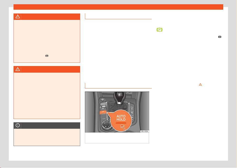
208
Parking and manoeuvring
WARNING
If the vehicle is left improperly, it could roll
aw
ay. This could lead to accidents, serious
injury and property damage.
●
When parking the vehicle, always perform
the appropriate operations in the indicated
order ›››page206, Parking.
●
Before leaving the vehicle, make sure that
the electronic parking brake is applied and
that the control lamp
next to the gear se-
l
ector is red on the instrument cluster.
WARNING
The improper use of the electronic parking
br
ake can cause accidents and serious in-
jury.
●
Never use the electronic parking brake to
stop the vehicle, unless it is an emergency.
The braking distance is considerably longer.
Always use the brake pedal.
●
Never accelerate from the engine when a
gear range or a gear is engaged and the en-
gine is running. The vehicle could move, even
if the electronic parking brake is activated.
NOTICE
To prevent the vehicle from unintentionally
moving when parking it, first apply the elec-
tronic parking brake and then remove your
foot from the brake pedal.
Troubleshooting
The el
ectronic parking brake does not re-
lease.
The 12-volt battery is discharged.
●
Use the jump start ›››page318.
The electronic parking brake makes noises
●
When the electronic parking brake is applied
and released, noises may be heard.
●
The system performs automatic and audible
checks sporadically in the parked vehicle if
some time elapses without the electronic park-
ing brake being used.
Auto-Hold function
Fig.155 In the l
ower part of the centre
console: Auto Hold function button.
The Auto-Hold function holds the vehicle at a
st
andstill and prevents it from moving without it
being necessary to depress the brake pedal.
When the Auto-Hold function is active, the
control lamp on the instrument cluster
lights up green. The control light of the
›››Fig.155 butt
on remains on when the
Auto Hold function is connected.
Requirements
●
The driver's door is closed.
●
The driver’s seatbelt is buckled.
●
The engine is running.
Connecting and disconnecting
Press the Auto Hold button ›››
. The control
l
amp on the button goes out when the Auto
Hold function is switched o.
Switching on and o automatically
If the Auto Hold function was switched on via
the Auto Hold button before switching the igni-
tion o, the function will remain on the following
time the ignition is switched on.
If the Auto Hold function was not switched on,
it will automatically remain o next time the
ignition is engaged.
The Auto Hold function connects automatically
if the following conditions are met (all points
must be met at the same time):
Parking and manoeuvring
209
General information on parking systems
1. The vehicle is kept stationary with the brake
pedal on a flat surf
ace or on a slope.
2. The engine rotates “correctly”.
The Auto Hold function disconnects automati-
cally if the following conditions are met:
1. If any of the requirements of the function
are no longer met.
2. If the engine runs erratically or has any
anomaly.
3. If the engine stalls.
4. Manual gearbox: If the clutch and the ac-
celerator are pressed at the same time.
Automatic gearbox: If the accelerator is
pressed.
5. Automatic gearbox: If any of the tyres have
only minimal contact with the ground, e.g.
For example, if the axles are crossed.
WARNING
The smart technology of the Auto-Hold can-
not o
vercome the limits imposed by the laws
of physics and it only operates within the lim-
its of the system. Never allow the enhanced
convenience of the Auto-Hold function to in-
duce you to take any risk that compromises
safety.
●
Never leave the vehicle running with the
Auto Hold function switched on.
●
The Auto-Hold cannot always keep the ve-
hicle stopped on an uphill, or brake it su-
ciently on a downhill, e.g. on slippery or icy
surfaces.
NOTICE
Always deactivate the Auto-Hold function
bef
ore entering an automatic car wash fa-
cility. Failure to do so could cause damage
due to the automatic application of the park-
ing brake.
General information on
parking systems
Automatic brake operation
The automatic braking feature of a parking sys-
tem is used to reduce the danger of collision
when an obstacle is detected during a parking
manoeuvre.
Braking functions
Depending on the equipment, the following
systems are available:
●
Park assist plus manoeuvre braking function
›››page2
10.
●
Rear cross trac alert emergency brake
function ›››page233.
●
Assisted parking assistant emergency brake
function ›››page2
16.
●
Trailer Assist manoeuvre braking function
›››page231
Requirements
●
The vehicle is moving between approx.
3km/h and 8km/h when manoeuvring
●
A parking system is switched on.
The brakes are not automatically operated
when park assist is switched on automatically
while moving forward.
What happens in the event of automatic
braking?
If there is an obstacle, the system brakes the
vehicle to a standstill and keeps it stationary for
approx. 2 seconds. Press the brake!
Activate
●
Automatic braking is activated when the
driver switches a parking system on.
Deactivating
●
The automatic brake operation function de-
activates when a park assist system is switched
o.
●
OR: to temporarily deactivate the manoeuvre
braking function, press the
function button
on the park assist scr
een and change the set-
ting.
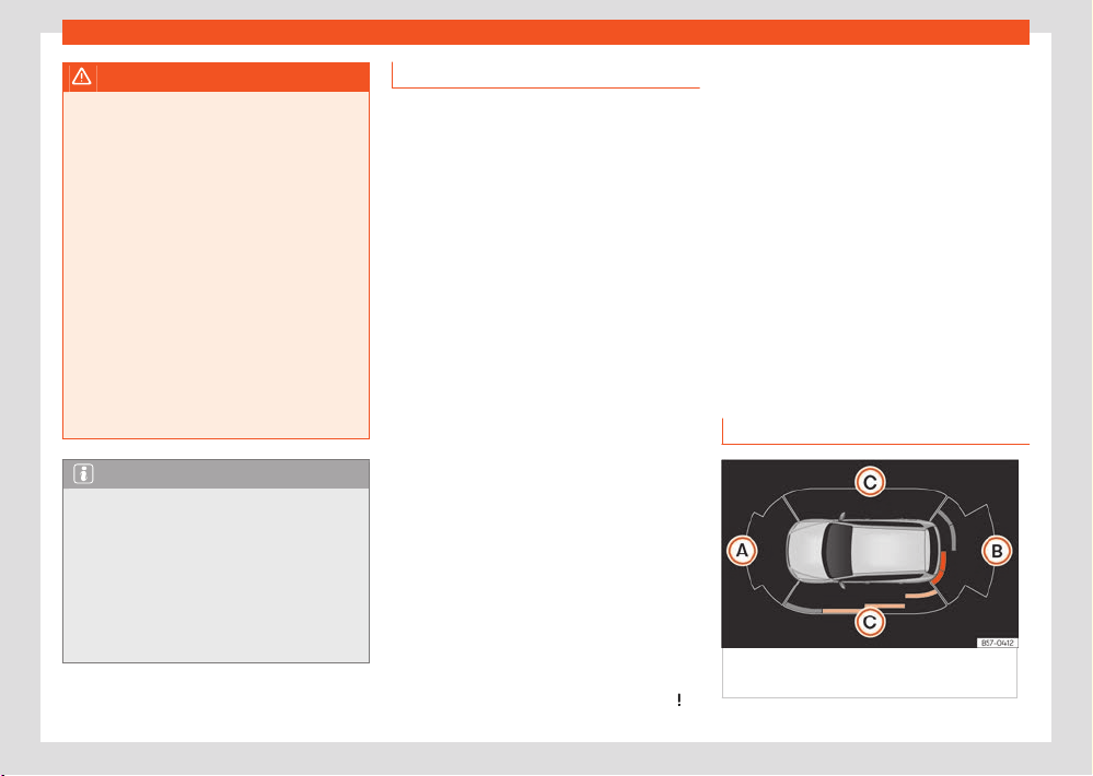
210
Parking and manoeuvring
WARNING
Never allow the automatic braking opera-
tions of park assist syst
ems to lead you to
take any risk that compromises safety. In
certain situations, the automatic braking in-
tervention may only work in a limited way
or not work at all. Collisions with obstacles
can injure people and damage the vehicle.
The system is not a replacement for driver
awareness.
●
Pay attention and do not rely solely on
park assist systems.
●
Always be prepared to brake and control
the steering yourself.
●
Do not take any risks that compromise
safety.
●
Act in accordance with the warnings and
driving recommendations of the parking sys-
tems.
Note
●
Switch o the parking syst
em if the auto-
matic brakes operate excessively, e.g. when
driving o-road.
●
After the park assist’s manoeuvre braking
function has braked the vehicle, driving in the
same direction for 5 metres is deactivated,
and becomes active again after changing
gear or changing the position of the gear se-
lector.
Troubleshooting
The parking syst
em behaves dierently than
expected
There can be several causes:
●
The system requirements are not met.
●
The sensors or the camera are dirty or have
ice on them ›››page368.
●
The camera lens is not clean and the camera
image is not cl
ear ›››page368.
●
Some noise sources, such as a jackhammer
or a cobblestone surface can interfere with the
ultrasound signal.
●
The vehicle has some type of damage in the
sensor or camera area, e.g. due to a parking
impact.
●
The sensor detection zone or field of view of
the camera are blocked by an accessory, e.g. a
bike rack.
●
Changes have been made to the paintwork
or structural modifications in the sensor or
camera area, e.g. at the front of the vehicle or
to the running gear.
Also take into account the messages displayed
on the infotainment system screen.
Sensor or camera without visibility, or the
parking system has been switched o
If a sensor fails, that sensor zone is permanently
switched o. The aected sensor zone may be
displayed on the infotainment system with a
symbol and a greyed-out graphic segment. If
necessary, the parking syst
em switches o the
aected zone.
If the park assist is not working properly, a con-
tinuous audio signal sounds for a few seconds
when it is switched on. If applicable, a message
to this eect is displayed on the instrument
cluster screen
●
Check if one of the causes indicated above
has occurred.
●
Once the source of the problem has been
eliminated, the system may be reconnected.
●
If the problem persists, consult a specialised
workshop.
Parking aid Plus
Description
Fig.156 P
arking aid view on the Infotainment
system display.
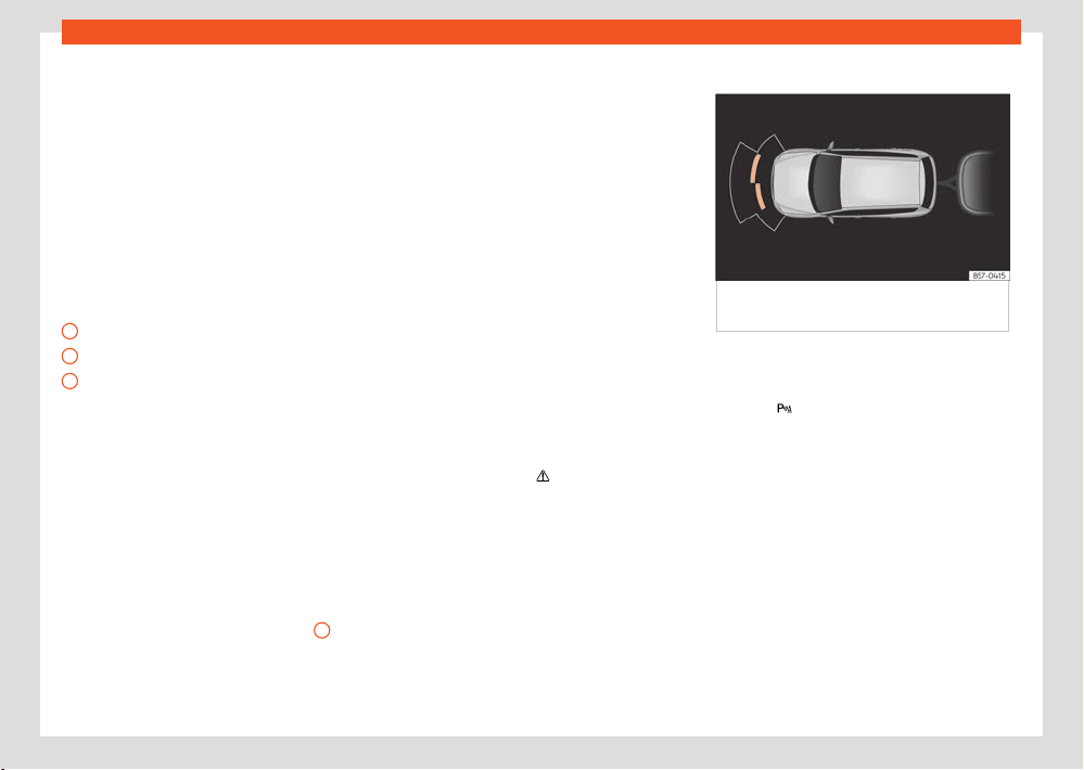
Parking and manoeuvring
211
Parking aid Plus
A
B
C
Parking aid plus assists the driv
er by giving
visual and audio warnings about obstacles de-
tected in front of and behind the vehicle.
The bumpers are fitted with sensors. When
an obstacle is detected, it is indicated by au-
dible signals and in the Infotainment system
›››Fig.156.
When moving close to an obstacle, it is possible
to know if the obstacle is in front of the vehicle
or behind it according to the sound frequency.
The approximate measurement range of the
sensors is:
1.20 m
1.60 m
0.90 m
As you approach the obstacle, the frequency of
the audible signals will increase. The signal will
sound continuously at around 0.30 m: Stop the
vehicle!
If the separation is maintained, the warning vol-
ume is reduced after about 4 seconds.
In order to view the entire periphery of the vehi-
cle, the vehicle must be moved a few metres
forwards or backwards. Therefore, the missing
areas are screened and obstacles at the sides
of the vehicle are displayed ›››Fig.156
C
.
Special features of ParkPilot with Area View
In the f
ollowing situations the screened area on
the side of the vehicle is automatically hidden:
●
When a vehicle door is opened.
●
When the TCS is switched o.
●
When there is TCS or ESC regulation.
●
If the vehicle remains stationary for more than
approximately 3 minutes.
Error messages
If a an error or fault message is displayed on
the instrument cluster in Park Assist, there is a
fault.
If the fault doesn't disappear before discon-
necting the ignition, it will not be indicated next
time the parking aid is connected.
If a rear sensor is faulty, only the obstacles in
the front area are detected. If a front sensor is
faulty, only the obstacles in the rear area are
displayed. The symbol
is displayed.
W
e recommend taking the vehicle to a special-
ised workshop to have the fault repaired.
Trailer mode
Fig.157 P
arking assist display on the screen
with trailer attached.
On vehicles with a f
actory-fitted trailer hitch,
when the trailer is connected, the rear sensors
will not activate when reverse gear is engaged
or button
is pressed. Therefore, any objects
behind or t
o the side of the vehicle will not be
indicated on the screen and no audio signals
will sound.
The screen will only display objects detected
at the front, and the vehicle's trajectory will be
hidden.
Parking assist settings
The audio indications and signals are set in the
infotainment system ›››page37:
●
Automatic activation: On/o
●
Front volume: V
olume in the front and rear
area.
●
Rear volume: V
olume in the rear area.
212
Parking and manoeuvring
●
Reduce volume: When the parking aid is
s
witched on, the volume of the audio source will
be reduced, depending on the selected option.
●
Front sound settings/treble: Sound
t
one in the front area.
●
Rear sound settings/treble: Sound
t
one in the rear area.
WARNING
●
Always pay attention, by looking directly,
t
o trac and the area around the vehicle. As-
sistance systems are not a replacement for
driver awareness. Responsibility always lies
with the driver.
●
The sensors have blind spots in which ob-
stacles and people are not detected. Pay
special attention to children and animals.
●
Always keep visual control of the surround-
ings: use the mirrors for additional help.
NOTICE
Park assist plus functions can be aect
ed by
various factors which may cause damage:
●
Under certain circumstances, the system
does not detect or display certain objects:
–
Chains, trailer draw bars, bars, fences,
posts and thin trees.
–
Objects that are located above the sen-
sors, such as protrusions in a wall.
–
Objects with certain surfaces or struc-
tures, such as wire mesh fences or powder
snow.
●
Certain surfaces of objects and garments
do not reflect the ultrasound sensors' sig-
nals. The system cannot detect these ob-
jects or people wearing such clothes cor-
rectly.
●
Sensor signals may be aected by exter-
nal sound sources. This may prevent them
from detecting people or objects.
●
If the system warns you of the proximity
of a low obstacle, please note that after be-
ing detected by the system, the obstacle in
question may disappear from the measure-
ment sensors as the vehicle moves closer,
and the system will no longer warn of its
presence. In certain circumstances, objects
such as high kerbs that could damage the
underside of the vehicle are not detected.
●
If the parking distance warning system is
ignored, the vehicle could suer considera-
ble damage.
●
Damage to the radiator grille, bumper,
wheel arch and vehicle underbody can mod-
ify the orientation of the sensors. This can
aect the parking aid function.
Have the function checked by a specialised
workshop.
●
A number plate or number plate holder
with dimensions that exceed the space for
the number plate, or a cured or deformed
number plate can cause false detections or a
loss of visibility for the sensors.
Note
●
The display on the Infotainment system
scr
een shows a slight time delay.
●
In certain situations, the system can give a
warning even though there is no obstacle in
the detected area:
–
Rough or cobbled surfaces or surfaces
with long grass.
–
External ultrasound sources, such as
other vehicles equipped with ultrasound
systems.
–
Heavy rain or snow, hail or dense exhaust
gases.
–
If the number plate is not properly se-
cured to the surface of the bumper.
–
Gradient changes.
●
In order to guarantee good operation, keep
the sensors cl
ean, free of snow and ice, and
do not cover them with stickers or other ob-
jects.
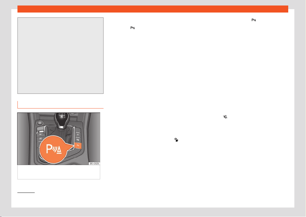
Parking and manoeuvring
213
Parking aid Plus
1)
The RVC button will only be displayed when reverse gear is engaged.
●
If you use high-pressure or vapour equip-
ment f
or cleaning, do not apply it directly,
unless you do so very briefly, and always
keep a distance of more than 10 cm away.
●
Fitting certain accessories to the front of
the vehicle, such as a plate holder with ad-
vertising, may interfere with the operation of
the Park Assist.
●
We recommend that you practice parking
in an area without trac.
●
The volume and tone of the signals and
indications can be changed.
●
Please observe information on towing a
trailer.
Operating Park Assist Plus
Fig.158 Centr
e console: parking aid button
(depending on the version).
Switching on and o manually
●
Press the
button once.
Aut
omatic activation
●
Select reverse gear.
●
EITHER: if you drive forward at a speed of less
than 15 km/h (9 mph) and an obstacle is en-
countered, it is detected when it is approx. less
than 95 cm. away. If the automatic connection
is activated, a reduced view is shown.
●
OR: if the vehicle moves backwards.
When the Plus Parking Aid connects automat-
ically, a diagram of the vehicle and the seg-
ments will appear on screen.
It only operates every time the speed drops be-
low 15 km/h (9 mph) for the first time.
Automatic activation of park assist can be
switched on and o in the infotainment system:
●
Switch the ignition on.
●
In the infotainment system, select
> Set-
tings > Parking and manoeuvring.
●
Check the Automatic activation bo
x.
●
OR, in the parking assist
ance function, select
Settings > Automatic activation.
If activated automatically, an audible sound
warning will only be given when obstacles in
front are at a distance of less than 50 cm. ap-
prox.
If it is switched o using the
button, one of
the f
ollowing actions must be taken for it to re-
activate automatically:
●
Switch o the ignition and switch it on again.
●
EITHER:drive forward at over approx. 15km/h
(9mph).
●
OR: move the lever into position P and back
again.
●
OR: switch the automatic activation on and
o in the Infotainment system.
Automatic disconnection
●
Drive forward at 15 km/h (9mph) or faster.
●
OR: move the selector lever to position P.
Temporary sound suppression
●
Press the
function button on the infotain-
ment scr
een.
Change from reduced view to full view
●
Select reverse gear.
●
Press the car icon on the reduced view
Switch to the reverse assist image (Rear
View Camera “RVC”)
●
Select reverse gear.
●
OR pr
ess the RVC function button
1)
.
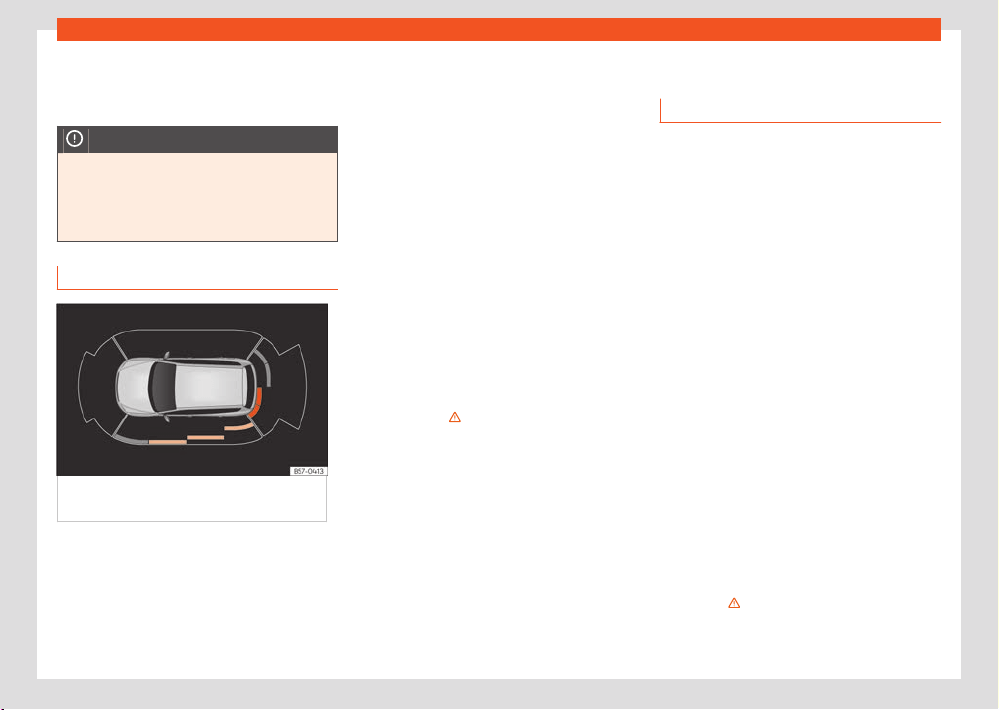
214
Parking and manoeuvring
A short confirmation signal will be hear
d and
the button symbol will light up when the system
is switched on.
NOTICE
Park assist plus only connects automatically
when driving v
ery slowly. If driving style is
not adapted to the circumstances, an acci-
dent and serious injury or damage may be
caused.
Visual indication segments
Fig.159 P
arking aid view on the Infotainment
system display.
The optical indication of the segments works as
f
ollows:
●
White segments: the obst
acle is more than
approx. 30 cm away from the path or in the
direction opposite to travel. They are also dis-
played when the electronic parking brake is ac-
tivated.
●
Yellow segments: the obstacles lie on the
vehicle’s path and are at a distance of less than
approx. 30 cm away.
●
Red segments: obstacles are less than ap-
prox. 30 cm away.
A guiding track will indicate the anticipated for-
ward or backward trajectory, depending on the
gear that is engaged.
If an obstacle is located in the vehicle’s way, the
corresponding audible warning will sound.
When the penultimate segment is displayed,
the vehicle has reached the collision zone. In
the collision zone, the obstacles are represen-
ted in red (including those out of the path). Stop
the vehicle! ›››
in Description on page2
12
In the event the car is equipped with the Top
View Camera system, Park Assist visual guid-
ance will appear in accordance with the view
selected in the Top View Camera system.
Rear parking aid
Description
The rear park assist is an optical and audible
assistant that warns of obstacles located be-
hind the vehicle.
There are sensors integrated in the rear
bumper. When they detect an obstacle, you are
alerted by audible and visible warnings on the
Infotainment system.
If the Top View Camera system is installed, the
rear parking aid will issue an audible warning
about objects near the rear of the vehicle, and
the Top View Camera image will be available
on the infotainment screen, giving a real image
of the objects around the car.
Make particularly sure that the sensors are not
covered by adhesives, residues, dirt and the
like, as this could aect the system's operation.
Cleaning instructions ›››page368.
The approximate measurement range of the
rear sensors is:
●
Side area: 0.60 m
●
Central area: 1.60 m
As you appr
oach the obstacle, the frequency of
the audible signals will increase. The signal will
sound continuously at around 0.30 m: Stop the
vehicle! ››› on page212.
If the separation is maintained, the warning vol-
ume is reduced after about 4 seconds.
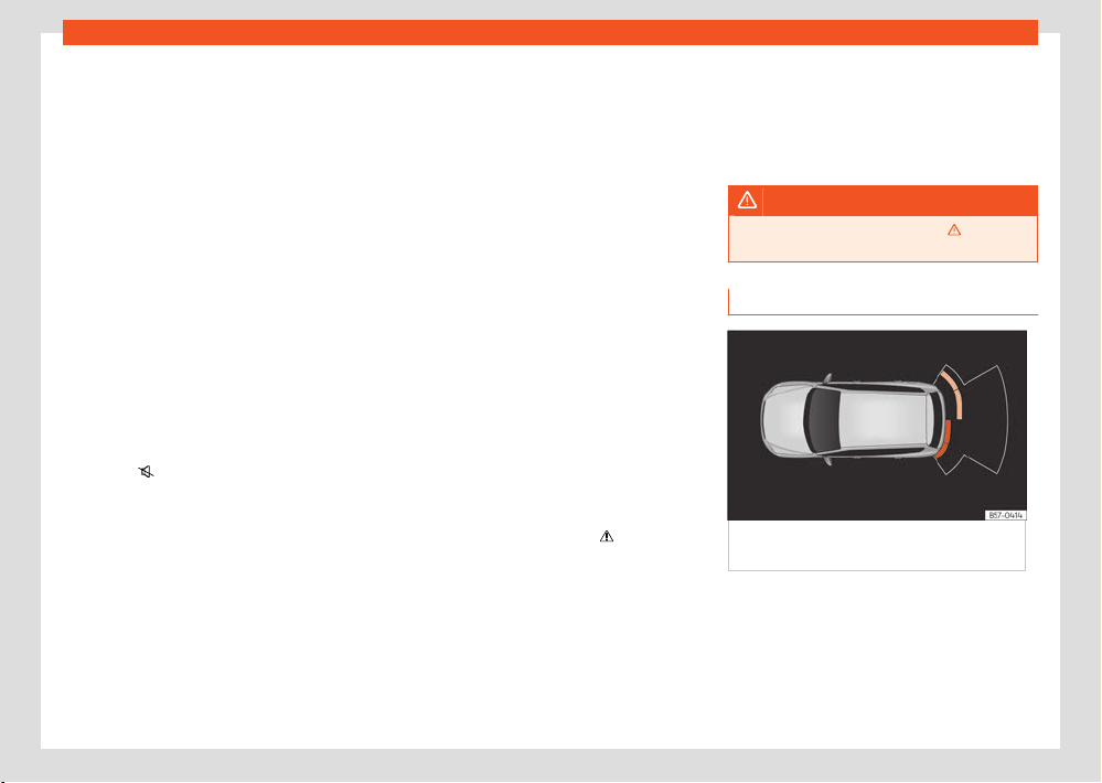
Parking and manoeuvring
215
Rear parking aid
Parking Aid connection
●
Select reverse gear.
P
arking Aid disconnection
●
Drive forward at 15 km/h (9mph) or faster.
●
OR: place the selector level in position P, N
or D (for automatic gearboxes) or disengage
reverse (for manual gearboxes).
Set the lever to the N or D position to maintain
the system active for approximately 8 seconds
before switching o. During this time, the Park-
ing aid will be deactivated if the selector lever is
set to P.
If the Top View Camera system is installed, rear
parking aid will be automatically deactivated
when disengaging reverse gear.
Temporary sound suppression
●
Press the
function button on the infotain-
ment scr
een.
If you have the Top View Camera system instal-
led, you cannot use the temporary Parking Aid
sound suppression.
Change from reduced view to full view
●
Select reverse gear.
●
OR: on vehicles fitted with reverse assist
(Rear View Camera “RVC”) press on the car
icon of the reduced display.
Switch to the reverse assist image (Rear
View Camera “RVC”)
●
Select reverse gear.
●
OR: press the “RVC” function button.
Parking assist settings
The audio indications and signals are set in the
infotainment system ›››page37:
●
Rear volume: Volume in the rear area.
●
Reduce volume: When the parking aid is
s
witched on, the volume of the audio source will
be reduced, depending on the selected option.
●
Rear sound settings/treble: Sound
t
one in the rear area.
Error messages
If a an error or fault message appears on the in-
strument panel in Parking assist, there is a fault.
If the fault doesn't disappear before discon-
necting the ignition, it will not be indicated next
time the parking aid is connected.
If there is a fault in a sensor, the
symbol is
displ
ayed on the infotainment system display.
We recommend taking the vehicle to a special-
ised workshop to have the fault repaired.
Towing device
In v
ehicles equipped with a towing bracket de-
vice from the factory, when the trailer is con-
nected, the parking aid will not be activated
when reverse gear is engaged.
WARNING
Observe the safety warnings ››› in De-
scription on page2
12.
Visual indication segments
Fig.160 P
arking aid view on the Infotainment
system display.
The distance to the obstacles can be estimated
with the help of the segments at the r
ear of the
vehicle.
The optical indication of the segments works as
follows:
216
Parking and manoeuvring
●
White segments: the obst
acle is more than
approx. 30 cm away from the path or in the
direction opposite to travel. They are also dis-
played when the electronic parking brake is ac-
tivated.
●
Yellow segments: the obstacles lie on the
vehicle’s path and are at a distance of less than
approx. 30 cm away.
●
Red segments: obstacles are less than ap-
prox. 30 cm away.
Whenever the obstacle is located in the vehi-
cle’s direction of travel, the corresponding audi-
ble warning will sound.
When the penultimate segment is displayed,
the vehicle has reached the collision zone. In
the collision zone, the obstacles are represen-
ted in red (including those out of the path). Stop
the vehicle! ›››
in Description on page2
12.
If fitted with Top View Camera, the segment
display is not shown. The Parking assist system
will issue an audible warning for objects that
are near the rear of the vehicle, and the Top
View Camera image will be shown on the info-
tainment system display, giving a real image of
the objects around the car.
Parking aid system (Park
Assist)
Introduction
The assisted parking system is an additional
function of ParkPilot ›››page210 and helps
the driver find a suitable parking space from
among the following types:
●
park driving in reverse in suitable perpendic-
ul
ar and parallel spaces,
●
park driving forwards in suitable perpendicu-
lar spaces,
●
exit a parking space driving forwards from a
parallel space.
In vehicles with a Park Assist system and factory
infotainment system, the front, rear and side
areas are represented, and the position of ob-
stacles is shown relative to the vehicle.
The assisted parking system is subject to cer-
tain limitations inherent to the system and
its use requires special attention by the
driver››› .
WARNING
The technology used in the park assist sys-
t
em involves a series of limitations inherent in
the actual system and in the use of ultrasonic
sensors. The use of Park Assist should never
tempt you to take any risk that may compro-
mise safety. The system is not a replacement
for driver awareness.
●
Any accidental movement of the vehicle
could result in serious injury.
●
Adapt your speed and driving style at all
times to suit visibility, weather, road and
trac conditions.
●
Certain surfaces of objects and garments
do not reflect the ultrasound sensors' sig-
nals. The system cannot detect, at least cor-
rectly, these objects or people wearing such
clothes.
●
Ultrasound sensor signals may be aected
by external sound sources. In certain circum-
stances this may prevent them from detect-
ing people or objects.
●
The ultrasound sensors may have blind
spots in which obstacles and people are not
detected.
●
Monitor the area around the vehicle at all
times, since the ultrasound sensors do not
detect small children, animals or certain ob-
jects in all situations.
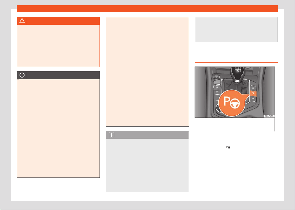
Parking and manoeuvring
217
Parking aid system (Park Assist)
WARNING
Quick turns of the steering wheel when park-
ing or e
xiting a parking space with Park As-
sist can cause serious injury.
●
Do not hold the steering wheel during ma-
noeuvres to park or exit a parking space un-
til the system requests it. Doing so disables
the system during the manoeuvre, resulting
in the parking being cancelled.
NOTICE
●
In certain circumstances, the ultrasonic
sensors do not det
ect objects such as trailer
tongues, bars, fences, posts or thin trees, or
an open (or opening) rear lid, which could
damage the vehicle.
●
Retrofitting of certain accessories to the
vehicle, such as a bicycle rack, may interfere
with the operation of the Park Assist system
and cause damage.
●
The Park Assist system uses as a reference
parked vehicles, curbs and other objects.
Make sure that the tyres and wheels are not
damaged while parking. If necessary, oppor-
tunely interrupt the parking manoeuvre to
avoid damaging the vehicle.
●
The ultrasound sensors on the bumper may
be damaged or shifted in the event of a colli-
sion, for example, when entering or exiting a
parking space.
●
If you use high-pressure or vapour equip-
ment t
o clean the ultrasound sensors, do not
apply it directly unless very briefly and al-
ways from a distance of more than 10 cm.
●
A registration plate or plate holder on the
front with larger than the space for the reg-
istration plate, or a registration plate that is
curved or warped can cause:
–
False detections.
–
The sensors to lose visibility.
–
Cancellation of the parking manoeuvre
or defective parking.
●
If one of the ultrasonic sensors is dam-
aged, the area corresponding to that group
of sensors (front or rear) is deactivated and
cannot be activated until the fault is correc-
ted. However, you can still use the sensors
of the other bumper as per usual. If there
is a fault in the system, consult a specialist
workshop. SEAT recommends visiting a SEAT
dealership for this.
Note
●
In order to guarantee good system oper-
ation, k
eep the ultrasound sensors of the
bumper clean, free of snow or ice, and do not
cover them with adhesives or other objects.
●
Certain sources of noise, such as rough as-
phalt or paving stones and the noise of other
vehicles can induce the Park Assist system
or ParkPilot to give erroneous warnings. The
presence of metal objects can also aect
the manoeuvre.
●
In order to become familiar with the system
and its functions, SEAT r
ecommends that you
practice operating the Park Assist system in
an area where there is not too much trac or
in a car park.
Description of the parking assist sys-
tem
Fig.161 In the centr
e console: button to switch
on the Park Assist system.
The components of the Park Assist system are
the ultr
asonic sensors located in the front and
rear bumpers, the
button to switch the sys-
t
em on and o and the messages on the instru-
ment panel display.

218
Parking and manoeuvring
Prerequisites for parking
●
The traction control (TCS) must be switched
on ›››page1
75.
●
Speed when passing next to the parking
space (parallel parking): do not exceed approx.
40 km/h (25 mph).
●
Speed when passing next to the parking
space (angle parking): do not exceed approx.
20 km/h (12 mph).
●
Keep a distance between 0.5 and 2.0me-
tres when driving past the parking space.
●
Space length (parallel parking): vehicle
length + 0.8 metres.
●
Space width (parking bay): vehicle width
+ 0.8 meters.
●
Do not exceed approximately 7 km/h
(4mph) when parking.
Requirements for leaving the parking space
(only for parallel parking)
●
The traction control (TCS) must be switched
on ›››page175.
●
Space length: length of the vehicle
+ 0.5 metres.
●
Do not exceed approximately 7 km/h
(4mph) when exiting the parking space.
Prematurely stopping or automatically in-
terrupting the manoeuvres for parking or ex-
iting a parking space
Park Assist interrupts the manoeuvres for park-
ing or exiting a parking space in any of the fol-
lowing cases:
●
Press the
button.
●
When exceeding a speed of approximately 7
km/h (
4mph) more than once.
●
The driver takes control of the steering wheel.
●
The parking manoeuvre does not end within 6
minutes after activation of the automatic steer-
ing.
●
There is a fault in the system (the system is
temporarily unavailable).
●
The TCS is disconnected.
●
TCS or ESC intervene with regulation.
●
The Oroad or Snow driving profile is selec-
ted.
●
The driver door is opened.
To restart the manoeuvre it is necessary that
none of these things occur and that the
but-
t
on is pressed again.
Automatic braking intervention to avoid ex-
ceeding the speed limit
To avoid exceeding the allowed speed of ap-
prox. 7km/h (4mph) when entering or leaving
a parking space, the brakes may activate au-
tomatically. After automatically activating the
brakes, the manoeuvres to enter or exit a park-
ing space may continue.
The brakes are only automatically activated
once for each attempt to enter or exit a parking
space. If the speed of approximately 7km/h
(4mph) is exceeded again, the corresponding
operation is halted.
Special characteristics
The Park Assist system is subject to certain limi-
tations inherent to the system. For example, it is
therefore not possible to use it to enter or exit a
parking space on sharp bends or on very steep
hills.
While entering or exiting a parking space, a
brief signal sounds to prompt the driver to
change between forward and reverse gears
(depending on the case). In successive ma-
noeuvres, the assistant tells the driver to
change gears, at the latest, when the continu-
ous audible signal is given (object present at a
distance of ≤30cm) by Park Pilot.
When the Park Assist system turns the steer-
ing wheel with the vehicle stationary, the instru-
ment panel also displays the symbol
. Keep
the br
ake pedal depressed while the symbol
remains on the dash panel display to turn the
wheels with the vehicle stopped. This way, the
system will require fewer manoeuvres to com-
plete the parking action.
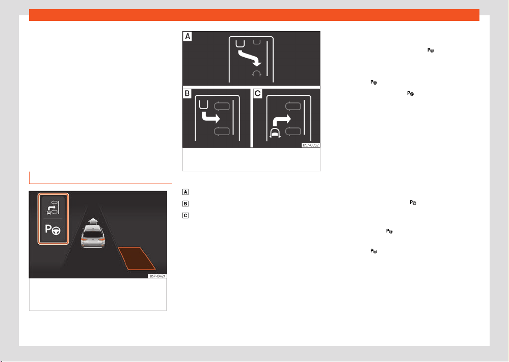
Parking and manoeuvring
219
Parking aid system (Park Assist)
Trailer mode
The P
ark Assist system cannot be switched on if
the factory-fitted towing bracket is electrically
connected to a trailer.
After changing a wheel
If, after changing a wheel, the vehicle stops
entering and exiting parking spaces correctly,
the circumference of the new wheel may be
dierent and the system may need to adapt to
it. The adaptation is automatic and takes place
during driving. Making turns slowly and in both
directions (20 km/h [12 mph]) for a few minutes
may contribute to this adaptation process.
Selecting a parking type
Fig.162 On the instrument panel displ
ay:
display of the assisted parking system with
decreased visibility.
Fig.163 On the instrument clust
er display:
parking modes indication.
Park assist has the following 3 parking types:
Reverse parallel parking.
R
everse angle parking.
Forward angle parking.
Selecting a parking type after passing in
front of the space
After activating the Park Assist system and
after detecting a parking space, the display
on the instrument panel proposes a parking
mode. The Park Assist system selects the park-
ing mode automatically. The selected mode
is shown on the instrument panel display
›››Fig.162. The reduced display of other possi-
ble parking modes is also shown ›››Fig.163. If
the mode selected by the system does not cor-
respond to the desired mode, you can select
another mode by pressing the
button.
●
The necessary conditions to park with Park
Assist hav
e to be met ›››page217.
●
Press the
button.
●
A control lamp on the button lights up
when the syst
em is switched on. Additionally,
the selected parking mode is shown on the
instrument panel display and the reduced dis-
play shows another parking mode it can be
changed to.
●
Turn on the corresponding turn signal to-
wards the side of the road where you are park-
ing. The instrument panel displays the side cor-
responding to the road. By default, if the turn
signal is not on, it parks on the right in the direc-
tion of trac.
●
If necessary, press the
button again to
change t
o the next parking mode.
●
Once you have switched to all possible park-
ing modes, if the
button is pressed again, the
syst
em switches o.
●
Press the
button again to switch the system
back on.
●
Follow the instructions displayed on the in-
strument panel whil
e paying attention to trac
and drive the vehicle past the parking space.

220
Parking and manoeuvring
Parking in a parking bay without driving past
first
Special case of perpendicul
ar parking space to
park forwards without driving past first:
●
The necessary conditions to park with Park
Assist have to be met ›››page217.
●
Move forward towards the parking space
while paying attention to trac and stop the
vehicle with the front part partially inside the
parking space.
●
Press the
button once.
●
A control lamp on the button lights up
when the syst
em is switched on. Additionally,
the selected parking mode is shown on the
instrument panel display without reduced dis-
play.
●
Let go of the steering wheel.
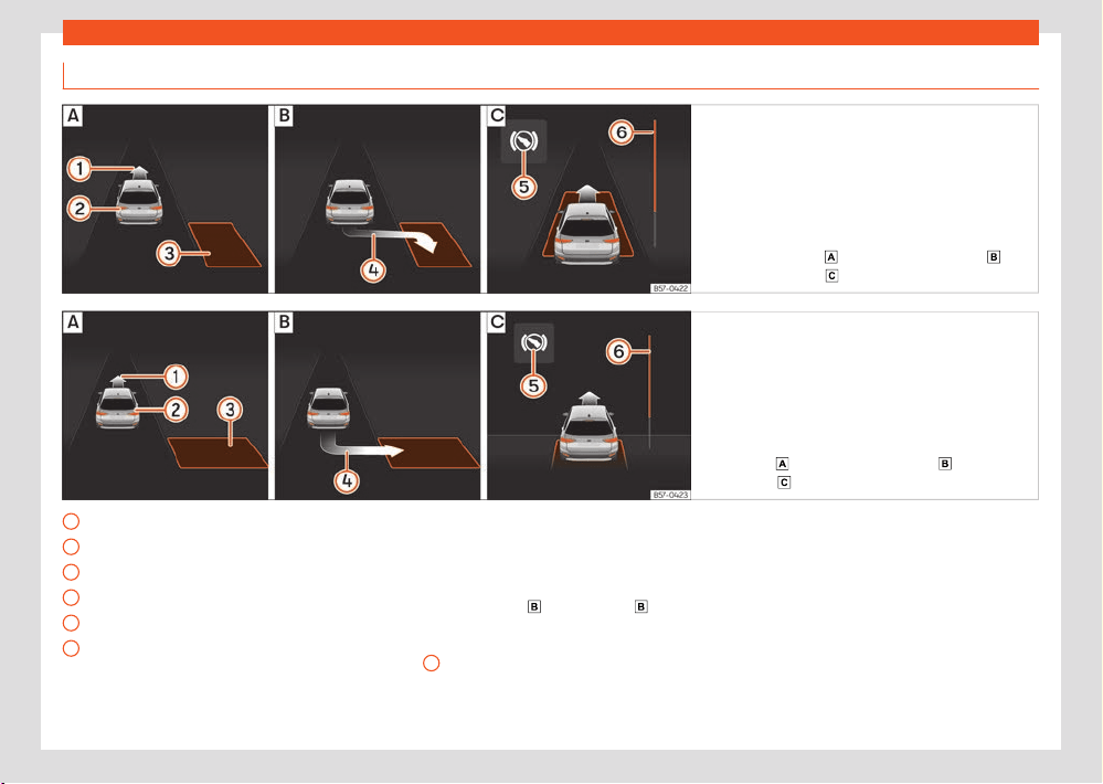
Parking and manoeuvring
221
Parking aid system (Park Assist)
1
2
3
4
5
6
Parking with the parking assist system
Fig.164 On the instrument clust
er display:
parallel parking.
: Finding a parking space :
P
arking position.
: Manoeuvring.
Fig.165 On the instrument clust
er display: angle
parking.
: Finding a parking space : Parking
position. : Manoeuvring.
Message to move forwards
Y
our vehicle
Parking space detected
Message to park
Message to press the brake pedal
Progress bar
The prerequisites have to be met to park with
the parking assist system ›››page217 and the
parking mode has to be selected ›››page219.
Parking
●
Look at the instrument cluster screen to see if
the space has been detected as “appropriate”
and if the correct position for parking has been
reached ›››Fig.164
or ›››Fig.165 . The
space is consider
ed “appropriate” if the instru-
ment cluster display shows the parking indica-
tion
4
.
●
Stop the vehicle and, after a brief pause, en-
gage the r
everse gear.
●
Let go of the steering wheel.
●
Please note the following message:
Intervention in active steering.
Watch your surroundings!
Whil
e keeping watch around you, carefully
start accelerating up to no more than 7 km/h
(4mph). During the parking manoeuvre, the
system only takes charge of the steering. You,
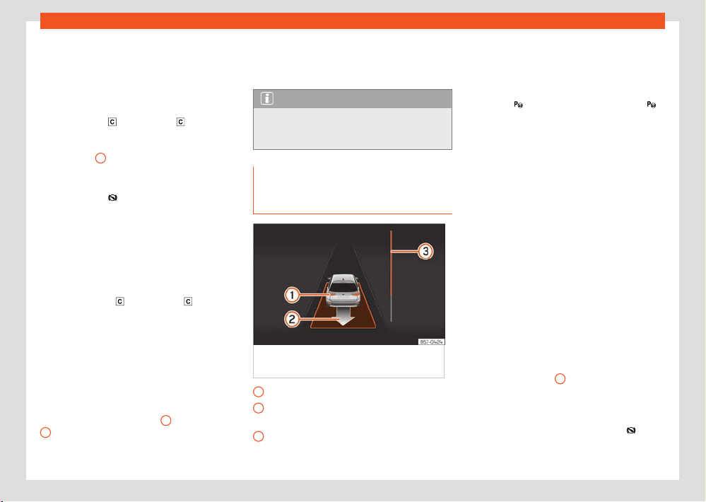
222
Parking and manoeuvring
1
2
3
as the driver, have to accelerate, engage
the clut
ch if necessary, change gears and
brake.
●
Reverse until the continuous ParkPilot signal
sounds; OR: reverse until the indication to move
forward appears on the instrument panel dis-
play ›››Fig.164
or ›››Fig.165 ; OR: r
everse
until the Park Assist finished message
appears on the instrument cluster display. The
progress bar
6
indicates the distance to cover.
●
Press the brake pedal until the parking assist
syst
em completes the steering wheel turns; OR:
until the symbol
goes out on the instrument
panel scr
een.
●
Select first gear.
●
Move forward until the continuous ParkPilot
signal sounds; OR: move forward until the re-
verse indication appears on the instrument
panel display. The Park Assist system steers the
vehicle forward and back until it centres it in the
space ›››Fig.164
or ›››Fig.165 .
●
For best results, wait at the end of each
manoeuvr
e until the Park Assist system has fin-
ished turning the steering wheel. The parking
manoeuvre ends when a corresponding mes-
sage is displayed on the instrument panel and,
in some cases, an acoustic signal sounds.
Progress bars
The progress bar ›››Fig.164
6
and ›››Fig.165
6
on the instrument cluster display shows the
r
elative distance to be covered as a symbol.
The greater the distance, the fuller the progress
bar. When driving forward, the content of the
pr
ogress bar decreases upwards, and when re-
versing, it decreases downwards.
Note
If the manoeuvre is terminated prematurely
during parking, the r
esult may not be the
best.
Leaving a parking space with the
parking assist system (only for par-
allel parking)
Fig.166 On the instrument panel displ
ay:
driving o from perpendicular parking.
Your vehicle in reverse gear
Message giving the pr
oposed manoeuvre
to exit the parking space
Progress bar to indicate the distance left to
cover
Leaving a parking space (parallel parking)
The necessary conditions t
o exit a parking
space with Park Assist have to be met
›››page217.
●
Press the
button. A control lamp on the
button lights up when the system is switched
on.
●
Turn on the corresponding turn signal towards
the r
oad you will enter when exiting the parking
space.
●
Select reverse gear.
●
Let go of the steering wheel. Please note the
following message:
Automatic steering enabled Pay at-
tention to your surroundings.
While keeping watch around you, carefully
start accelerating up to no more than 7 km/h
(4mph). When exiting the parking space, the
system only takes charge of the steering. You,
as the driver, have to accelerate, engage
the clutch if necessary, change gears and
brake.
●
Reverse until the continuous ParkPilot signal
sounds; OR: r
everse until the instrument panel
display shows the forward indication. The pro-
gress bar ›››Fig.166
3
indicates the distance
t
o cover.
●
Press the brake pedal until the parking assist
system completes the steering wheel turns; OR:
press the brake pedal until the symbol
goes
out on the instrument panel scr
een.

Parking and manoeuvring
223
Reverse Assist (Rear View Camera)
●
Move forward until the continuous ParkPilot
signal sounds; OR: mo
ve forward until the re-
verse indication appears on the instrument
panel display. The Park Assist system steers the
vehicle forward and back until it can exit the
space.
●
The vehicle can exit the space when a cor-
responding message is displayed on the instru-
ment panel and, in some cases, an acoustic
signal sounds. Take charge of the steering with
the turning angle set by the Park Assist system.
●
Paying attention to the trac, exit the parking
space.
Reverse Assist (Rear View
Camera)
Introduction
A camera installed in the rear lid handle assists
the driver with reverse parking or manoeuvring
›››page182.
The camera image is viewed together with ori-
entation lines projected on the Infotainment
system screen. Part of the bumper can be seen
at the bottom, which can be used by the driver
as a reference point.
Reverse assist modes
Depending on the equipment, the following
modes are available:
●
Angle parking: r
everse parking perpendicu-
lar to the road.
●
Parallel parking: reverse parking parallel to
the road.
●
Assistance function for hitching a trailer:
helps to hitch a trailer.
●
Cross trac: monitors cross trac.
Requirements
To park with reverse assist, the following re-
quirements must be met:
●
Do not exceed a speed of approx. 15km/h
(9mph).
●
Parking space width: vehicle width + 0.2 m.
●
Distance: approx 1 metre from the parking
space (parallel only).
●
Length of the parking space: approx. 8 m
(parallel only)
To display a real image, the following require-
ments must be met:
●
The luggage compartment rear door is
closed.
●
The surroundings are on a flat surface.
●
The vehicle should not be loaded very heavily
at the rear.
WARNING
●
The reverse assist does not make it possi-
bl
e to precisely calculate the distance from
obstacles and nor can it overcome the sys-
tem's own limits, hence its negligent use may
cause serious accidents and injuries if used
without due care. The driver should be aware
of his/her surroundings at all times to ensure
safe driving.
●
The camera lens expands and distorts the
field of view and displays the objects on the
screen in a way that is dierent from reality.
Distance perception is also distorted.
●
Due to the screen resolution or light con-
ditions, some items may be blurry or not dis-
played at all. Take care with thin posts, fen-
ces, railings or trees that might not be seen
on the screen and could damage the vehicle.
●
The reverse assist has blind spots where
it cannot see people or objects. Monitor the
vehicle's surrounding area at all times.
●
The system is not a replacement for driver
awareness. Supervise the parking manoeu-
vre and the vehicle's surrounding area at all
times.
●
Do not be distracted from the trac by
looking at the screen.
●
The images are only two-dimensional. Pro-
truding objects or holes in the road, for ex-
ample, are more dicult to detect or may not
be seen at all.
224
Parking and manoeuvring
/
●
Vehicle load modifies the r
epresentation of
the guide lines. The width represented by the
lines decreases with vehicle load. Pay spe-
cial attention to the surroundings when the
inside of the vehicle of the luggage compart-
ment are loaded.
●
In the following situations, objects or other
vehicles appear to be further away or closer
than they actually are. Pay special attention:
–
If moving from a flat surface to a slope
and vice-versa.
–
If the vehicle is heavily loaded.
–
When the vehicle approaches objects
that are not on the ground surface or that
protrude from it. These objects may be out-
side the camera angle when reversing.
Note
●
It is important to take great care and pay
special att
ention if the driver is not familiar
with the system.
●
The reverse assist reference lines disap-
pear when the rear lid is open.
Connecting and disconnecting
Connect the reverse assist
●
Select reverse gear.
●
OR: pr
ess button
.
Disconnect the reverse assist
●
Drive forward at a speed of at least 15 km/h
(9 mph).
Sho
wn on the display
The system’s functions and representations
may vary depending on the equipment.
The assistant's image view changes when the
factory-fitted tow hitch is electronically con-
nected to a trailer ›››page297.
Reverse assist functions and symbols
When the reverse assist is connected, you can
make adjustments using the function buttons.
Some adjustments are equipment-dependent.
Exit the current display
S
witch to angle parking ›››page225
Switch to parallel parking ›››page225
Switch to the trailer hitching assistance
function
Switch to cross trac
Adjust the display: brightness, contrast
and colour.
Switch to park assist ›››page210
Display/hide the parking aid view
T
urn the steering wheel (parallel parking)
Stop the vehicle (parallel parking)
Guide lines
Green horizontal lines: extension of the vehicle.
Red lateral line: when the steering wheel needs
to be turned the other way, a yellow line turns
red (parallel parking).
Yellow lines: vehicle path depending on the
steering angle.
Yellow auxiliary boxes: front and rear delimita-
tion of the parking space (parallel parking).
Green lateral line: point for turning the other
way when parking (parallel parking).
Red and green frame: outline of the vehicle
(parallel parking).
Assistance function for hitching a trailer
On vehicles with a factory-fitted towing device,
this function can be used to move the vehicle
close to a tow bar. Due to the high level of mag-
nification of the image in this mode, objects be-
hind the vehicle are seen very late.
Auxiliary lines are shown in the infotainment
system.
Red lines: position of the tow hitch.
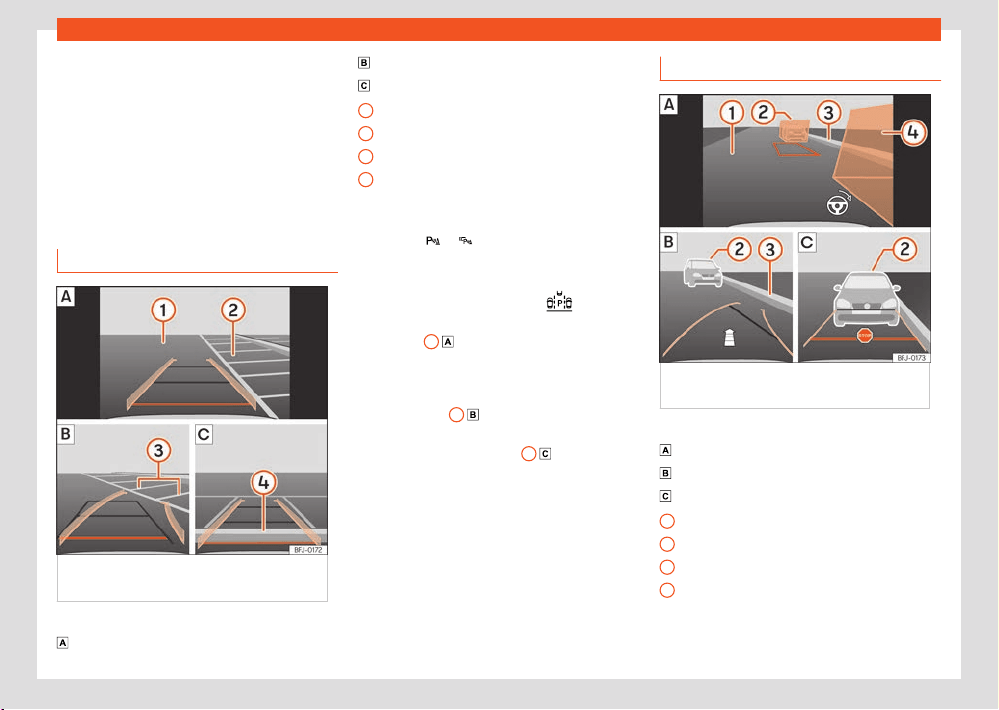
Parking and manoeuvring
225
Reverse Assist (Rear View Camera)
1
2
3
4
1
2
3
4
Green lines: distance to the tow hitch. The dis-
t
ance between the lines is approx. 0.1 m
Orange line: precalculated direction of the tow
hitch depending on steering wheel rotation.
Cross trac
This view helps to monitor trac behind the
vehicle and can be used, for example, when
exiting garages or narrow exits.
Angle parking
Fig.167 Displ
ay on the infotainment system
screen: parking with the reverse assistant.
Key to the ›››Fig.16
7:
Finding a parking space
Go to the selected parking space
Centre the vehicle inside the parking space
Road
Parking space
Lateral boundary of the parking space
Rear boundary of the parking space
Parking
●
Press the
or button before passing in
fr
ont of the selected parking space.
●
With reverse assist connected and in working
order, press the function button
.
●
Stop the vehicle in front of the parking space
›››Fig.16
7
2
.
●
Reverse while turning the steering wheel so
that the yell
ow lines enter the parking space.
The green and yellow lines must match the side
boundary lines
3
.
●
Stop the vehicle when the red line has
r
eached the rear boundary
4
.
Parallel parking
Fig.168 Displ
ay on the infotainment system
screen: reversing assistant, mode 2.
Key to the ›››Fig.168:
Finding a parking space
Go t
o the selected parking space
Centre the vehicle inside the parking space
Road
Obstacle or auxiliary box
Lateral boundary of the parking space
Obstacle or auxiliary box

226
Parking and manoeuvring
Parking
●
If necessary, press the button before
passing in fr
ont of the selected parking space.
●
With reverse assist connected and in working
order, press the function button
.
●
Turn on the corresponding turn signal on the
side of the r
oad where you want to park.
●
Place the vehicle parallel to the parking
space, approx. 1 meter away.
●
If obstacles protrude from the auxiliary boxes,
find another parking space or realign the vehi-
cle.
●
Select reverse gear. A red frame represents
the target position of your vehicle.
●
Turn the steering wheel until the red frame is
between the auxiliary boxes and has changed
to green. Keep the steering wheel in this posi-
tion and start driving slowly.
●
When an arrow appears, reverse. A yellow
line and a green line appear. The arrow indi-
cates the distance that still has to be covered.
●
While reversing, keep the steering wheel in
the adjusted position. Adjust the steering wheel
rotation correctly when an indication appears
on the steering wheel symbol
.
●
Reverse until the STOP signal is shown or
until the gr
een line matches up with the lateral
boundary of the parking space.
●
Stop the vehicle. Turn the steering wheel as
far as it’ll go in the opposite direction.
●
Reverse until the STOP signal is shown or until
the red line reaches the rear boundary.
Troubleshooting
The system behaves dierently than expec-
ted
There can be several causes:
●
The camera is dirty ›››page368. In addi-
tion to dirt and snow, camera visibility can be
reduced by detergent residue or any type of
coating.
●
The system requirements must be met
›››page223.
●
The camera is covered with water.
●
The factory-fitted towing bracket must
not be electrically connected to a trailer
›››page297.
●
The vehicle has some type of damage in the
camera area, e.g. due to a parking impact.
●
The field of view of the camera is blocked by
an accessory, e.g. a bicycle carrier system.
●
Changes have been made to the paint in the
camera area, or structural modifications have
been made to a component such as the run-
ning gear.
Camera with no visibility, fault message, the
system disconnects
●
Clean the camera or remove possible adhe-
sives or accessories from it ›››page368.
●
Check for visible damage.
Possible solution
●
Temporarily disconnect the system.
●
Check if one of the causes indicated above
has occurred.
●
Once the source of the problem has been
eliminated, the system may be reconnected.
●
If the system still behaves unpredictably,
have it checked by a specialised workshop.
Peripheral view system
(Top View Camera)
Introduction
Using 4 cameras, the system generates a rep-
resentation that is shown on the infotainment
system display. The cameras are located on
the radiator grille, the exterior mirrors and the
rear lid.
The functions and representations of the Area
View system may vary depending on whether
or not the vehicle has ParkPilot.
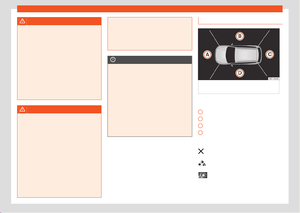
Parking and manoeuvring
227
Peripheral view system (Top View Camera)
A
B
C
D
WARNING
The image from the cameras does not make
it possibl
e to calculate the distance to the
obstacles (people, vehicles, etc.) precisely,
so using them could cause serious accidents
and injury.
●
The camera lenses augment and distort
the visual field and the objects on the screen
are seen dierently and imprecisely.
●
Certain objects may not be shown or may
not be shown very clearly, for example, posts
or thin rails, due to the screen resolution or if
light conditions are insucient.
●
The cameras have blind spots in which ob-
stacles and people are not registered.
WARNING
The smart technology incorporated into the
T
op View Camera system cannot overcome
the limits imposed by the laws of physics
and it only works within the limits of the sys-
tem. The greater convenience provided by
the Area View system should never tempt
you to take any risk that may compromise
safety. If used negligently or involuntarily,
it may cause serious accidents and injuries.
The system is not a replacement for driver
awareness.
●
Adapt your speed and driving style to
suit visibility, weather, road and trac condi-
tions.
●
Do not be distracted from the trac by
looking at the screen.
●
Monitor the area around the vehicle at
all times, since the cameras do not capture
small children, animals and certain objects in
all situations.
●
The system will probably be unable to rep-
resent all areas clearly.
NOTICE
●
The camera images are only two-dimen-
sional. Due t
o a lack of spatial depth, objects
that jut out or holes on the road, for example,
are more dicult to detect or may not be
seen at all.
●
In certain circumstances, the camera does
not capture objects such as beams, fences,
posts or thin trees, which could damage the
vehicle.
●
The system displays the auxiliary lines and
boxes regardless of the vehicle's environ-
ment, no objects are detected. The driver is
responsible for determining that the vehicle
will fit in the parking space.
Area View system
Fig.169 Displ
ay of the Area View system:
aerial view.
There are four dier
ent views to choose from
›››Fig.169:
Front camera area
Right camera area
Rear camera area
Left camera area
Function buttons:
Exit the current display.
Adjust the display: bright, contrast and
colour.
Three-dimensional views
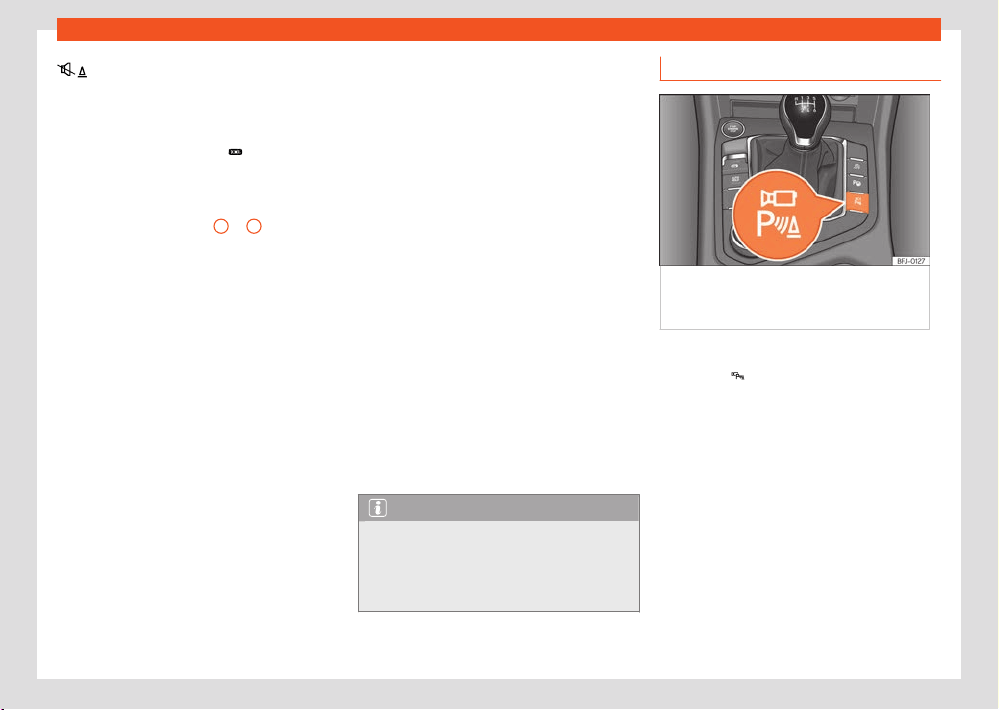
228
Parking and manoeuvring
Depending on the equipment: connect-
ing and disconnecting the P
arkPilot
sound.
The aerial view is generated by combining the
images from all the cameras
›››Fig.169.
The t
op view can be selected by pressing the
vehicle inside the zone.
Select the corresponding view by pressing the
dierent areas ›››Fig.169
A
to
D
of the top
vie
w or the reduced top view.
Conditions necessary for the use of the Area
View system
●
The doors and the rear lid must be closed.
●
The image must be reliable and clear. For this
reason, for example, the camera lens must be
clean.
●
The area around the vehicle must be clearly
and totally visible.
●
The area for parking or manoeuvring should
be a flat surface.
●
The vehicle should not be loaded very heav-
ily at the rear.
●
The driver must be used to the system.
●
There should be no damage to the vehicle in
the camera area. If the position or installation
angle of the cameras have been changed, e.g.
after a rear-end collision, the system should be
checked by a specialised workshop.
Special characteristics
The images on the area view system cameras
are only two-dimensional. Due to a lack of spa-
tial depth, it is dicult or impossible to make
out on-screen any holes there may be on the
ground, objects jutting out from the ground or
parts protruding from other vehicles.
Situations in which the objects or other vehicles
appear to be further away or closer than they
really are:
●
On moving from a horizontal plane to a slope.
●
On moving from a slope to a horizontal plane.
●
If the vehicle is heavily loaded at the rear.
●
If the vehicle approaches protruding objects.
These objects may be outside the cameras' an-
gle of visibility.
Trailer mode
The Area View system conceals, in the rear
camera area, all the auxiliary guiding lines
when the factory-fitted towing bracket is con-
nected electrically to a trailer ›››page297.
Note
In order to become familiar with the system
and its functions, SEAT r
ecommends that you
practice handling the Area View system in an
area where there is not too much trac or in
a car park.
Connecting and disconnecting
Fig.170 Centr
e console: button to manually
switch on/o the Top View camera system when
in combination with the parking assist system.
Manual activation
●
Press the
›››Fig.1
70 button once.
The infotainment system's screen shows the top
view ›››Fig.169. If you press the button when
driving above 15 km/h (9 mph), the image will
not be displayed.
Automatic activation
●
Select reverse gear.
●
EITHER: the vehicle moves backwards.
The view of the image of the vehicle's rear cam-
era is shown in parallel parking mode with the
reduced aerial view.
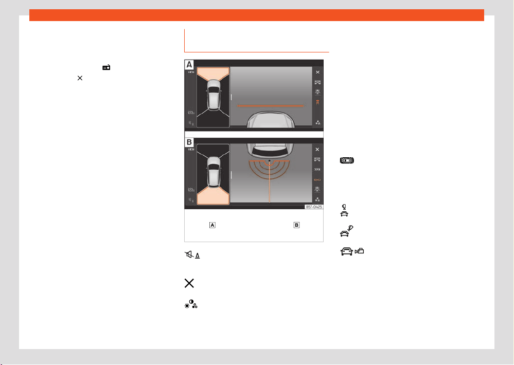
Parking and manoeuvring
229
Peripheral view system (Top View Camera)
Manual disconnection
●
Press the ›››Fig.1
70 button again.
●
EITHER: press a button on the infotainment
system, for example the
button.
●
OR: pr
ess the
function button.
Aut
omatic disconnection
●
Drive forward at a speed of at least 15 km/h
(9 mph).
●
OR: switch o the ignition. The Area View
system menu disappears immediately.
Views of the peripheral vision system
(modes)
Fig.171 Displ
ay on the Area View system
screen:
Front camera: o-r
oad view.
Rear
camer
a: o-road view.
Depending on the equipment: connect-
ing and disconnecting the P
arkPilot
sound.
Exiting the Area View system screen:
Adjust the display: bright, contrast and
colour.
The selected view is displayed on the right side
of the scr
een. The reduced aerial view shown
on the right side displays the view framed
in yellow. In addition, the right margin of the
screen displays the menu options possible and
the views (the so-called “modes”) of the cam-
era in question. The active view (mode) at the
time is highlighted.
The red lines are indicate a distance of approx.
40 cm away from the vehicle.
Aerial views (bird's eye view)
Main mode:
The vehicle and its immediate vicinity
seen from above are shown. Depending
on the equipment, the ParkPilot's path
may also be displayed.
Three-dimensional views:
The vehicle and its vicinity seen from above
are shown.
The vehicle and its vicinity seen from
above are shown obliquely.
The vehicle and its vicinity seen obli-
quely are shown.
Swipe the infotainment system display with
your finger in the direction of the arrows to
change the angle of vision in the three-dimen-
sional views of the vehicle and its vicinity.
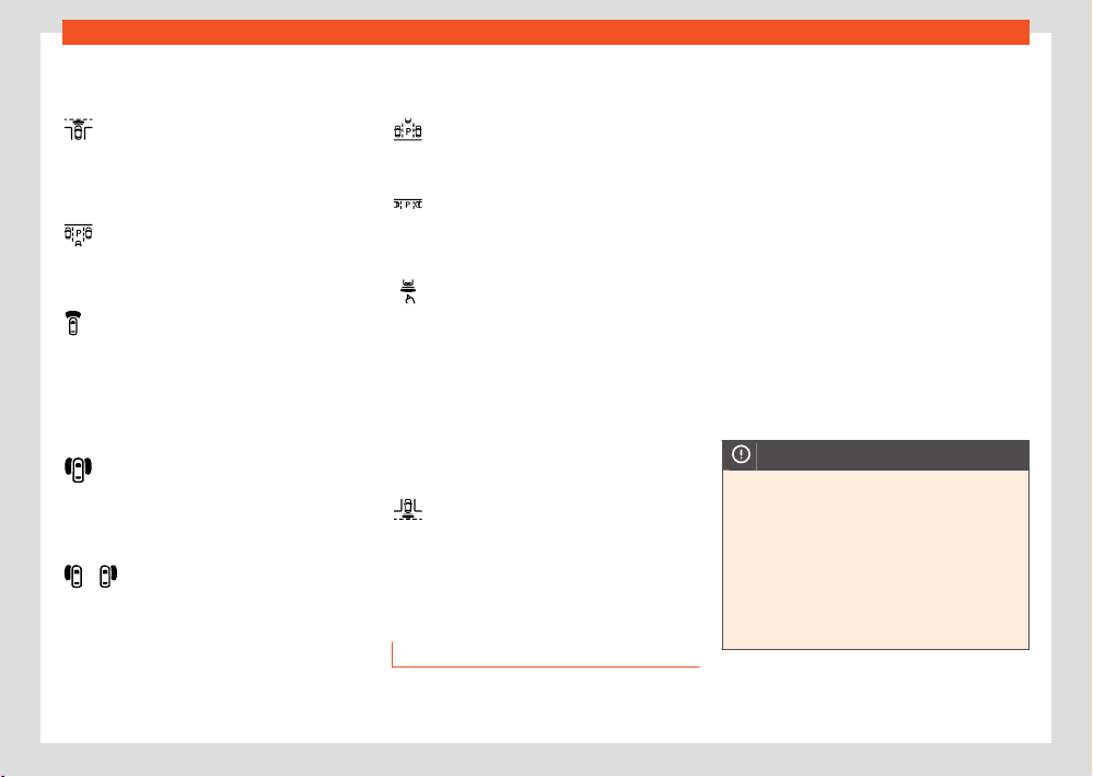
230
Parking and manoeuvring
/
Front camera views (front view)
Cr
oss trac.
This visualization helps to monitor trac
to the left, front and right of the vehicle
and can be used, for example, when exit-
ing garages or narrow exits
Angle parking.
The area in front of the vehicle is shown.
Orientation lines are shown to give guid-
ance.
O-road.
The area directly in front of the vehicle
seen from above is shown. For example, on
a slope, in order to see the area directly in
front of the vehicle.
Side camera views (side view)
Right and left sides.
The areas located directly to the side of
the vehicle seen from above are repre-
sented in order to navigate possible ob-
stacles more precisely.
Driver or passenger side seen from above.
This makes it possible to visualize the
blind spots along the vehicle.
Rear camera views (rear view)
Angle parking.
The area behind the vehicle is shown.
Auxiliary lines are shown to give guidance.
Parallel parking.
The area directly behind the vehicle is
shown. The coloured boxes and auxiliary
lines serve as orientation.
O-road or hitching a trailer function.
The vehicle's rear is presented. Green
and red semicircular auxiliary lines are
displayed in vehicles with a factory-fitted
towing bracket. The auxiliary lines indicate
the distance from the towing bracket. The
distance between the auxiliary lines (green
and red) is approx. 30 cm The orange aux-
iliary line indicates, according to how the
steering wheel is turned, the precalculated
direction of the towed device.
Cross trac.
This visualization helps to monitor trac
to the left, front and right of the vehicle
and can be used, for example, when exit-
ing garages or narrow exits.
Trailer Assist
Introduction
Trailer assist helps the driver to reverse and ma-
noeuvre with a trailer.
By moving the rotary knob of the exterior mir-
rors, the trailer assist directs the trailer that is
hitched. The driver has to accelerate, change
gears and brake!
System limitations
Under certain circumstances, the camera does
not detect objects such as trailer draw bars,
bars, fences, posts or thin trees, or an open (or
opening) rear lid, which could damage the ve-
hicle.
In order to guarantee good system operation,
keep the camera clean, free of snow or ice, and
do not cover it with adhesives or other objects.
Do not allow the draw bar to be covered by
external influences.
Use the trailer manoeuvre assistant only when
the rear lid is closed correctly.
NOTICE
The trailer maneuver assistant does not take
the v
ehicle’s surrounding as a reference. No
obstacle detection takes place. The driver
alone has to assess whether it is possible to
manoeuvre safely with the tow vehicle and
trailer set.
●
Always observe the movement of the
trailer and, if necessary, actively interrupt
the manoeuvre to avoid damage. Even if
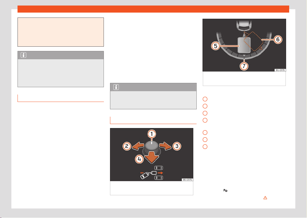
Parking and manoeuvring
231
Trailer Assist
1
2
3
4
5
6
7
the trailer manoeuvring assistant is operated
corr
ectly, on rare occasions the trailer may
move in a dierent way to the setting.
●
Do not rely solely on the indications on the
instrument cluster display.
Note
The trailer manoeuvre assistant automati-
cally s
witches o approx. 10 minutes after
being activated. The assistant is also deacti-
vated if the driver does not perform any ac-
tion over the course of approx. 3 minutes.
Requirements
The following requirements must be met for the
trailer manoeuvre assistant to work:
●
The engine is running.
●
The ESC must be connected.
●
The driver's door and the rear lid are closed.
●
The exterior mirrors are not folded.
●
There is a non-articulated one or two axle
tr
ailer hitched and electrically connected.
●
Both the tow vehicle and trailer are stopped.
●
The maximum bending angle has not been
exceeded.
●
The length of the trailer’s drawbar has been
determined.
Determine the length of the trailer's drawbar
In or
der for the trailer manoeuvre assistant
to determine the length of the trailer’s draw-
bar, drive the vehicle-trailer set through some
turning manoeuvres or curves. The more pre-
cisely the length of the drawbar is determined,
the wider the angles that will be available
when manoeuvring. The assistant subdivides
the maximum available end stops of the angle
indicator into four levels: approx. 30°, 45°, 60°
and 75°.
Note
For technical reasons, the trailer manoeu-
vr
e assistant cannot always correctly detect
trailers with LED technology taillights.
Operating
Fig.172 Outside r
earview mirror rotary control:
adjust the trailer angle.
Fig.173 Instrument clust
er display: engage
reverse.
Key to the ›››Fig.1
72 , ›››Fig.173:
Rotary exterior mirror controls.
Trailer orientation to the left
Trailer orientation to the right
Move the vehicle in the direction of the tow-
ing device.
Actual trailer position
Target trailer position
Angle indicator zero position
Manoeuvre with the tow vehicle and trailer
set
The system requirements must be met
›››page231.
●
Select reverse gear.
●
Press the
button.
●
Let go of the steering wheel ››› .
232
Parking and manoeuvring
●
Tilt the rotary control until the desired direc-
tion is r
eached ›››Fig.172. A representation of
the tow vehicle and trailer set is shown on the
instrument cluster screen for guidance purpo-
ses ›››Fig.173.
●
Reverse by accelerating slowly. Pay attention
to your surroundings!
●
If necessary, correct the angle with the rotary
control. Press the control towards the left or
right: the set will move to the left or right. Press
the control backwards: the vehicle will follow
the trailer.
●
Reverse and move forwards until the desired
position is reached.
●
The manoeuvre ends when a message is dis-
played on the instrument cluster display and, in
some cases, an audio signal sounds.
Automatic brake operation
The trailer manoeuvre assistant helps the driver
by automatically operating the brakes in cer-
tain situations.
The driver is responsible for braking on
time›››
.
The br
akes may be applied automatically and
the function deactivated in the following situa-
tions:
●
A certain speed is exceeded.
●
The steering wheel is grabbed. The vehicle
brakes automatically until it stops.
●
If the button
is pressed during the manoeu-
vr
e or the driver’s door opens.
WARNING
The quickly turning steering wheel can cause
serious injuries.
●
Do not hold the steering wheel during the
manoeuvr
e until the system requests it.
●
Exception: If a dangerous situation occurs,
intervene and take over the steering.
WARNING
Never allow the automatic operation of
br
akes to lead you to take any risk that com-
promises safety. The system is not a replace-
ment for driver awareness.
●
The manoeuvre assist system is subject
to certain limitations inherent to the system.
In certain situations, the automatic braking
intervention may only work in a limited way
or not work at all.
●
Always be ready to use the brakes your-
self!
●
Automatic brake operation ends after 1.5
seconds approx. if the vehicle is stopped. Af-
ter this, brake the vehicle yourself.
Note
The exterior mirrors cannot be adjusted while
the assist
ant is active. The saved setting
for the passenger’s mirror can be activated
›››page129.
Troubleshooting
Camera with no visibility, fault message, the
system disconnects
●
Clean the camera or remove possible adhe-
siv
es or accessories from it ›››page368.
●
Check for visible damage.
The system behaves dierently than expec-
ted
There can be several causes:
●
The camera is dirty ›››page368. In addi-
tion t
o dirt and snow, camera visibility can be
reduced by detergent residue or any type of
coating.
●
The system requirements must be met
›››page231.
●
The camera is covered with water.
●
The vehicle has some type of damage in the
camera area, e.g. due to a parking impact.
●
The fiel
d of view of the camera is blocked by
an accessory, e.g. a bicycle carrier system.
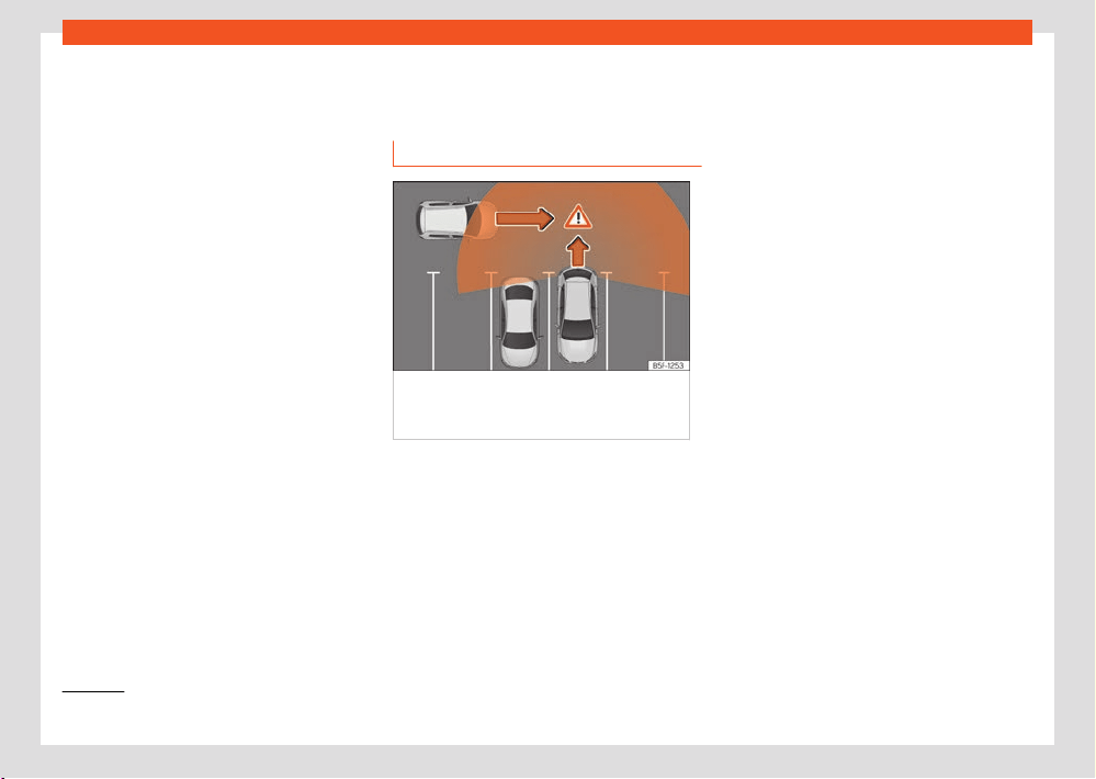
Parking and manoeuvring
233
Rear cross tr
ac alert (RCTA)
1)
It is only displayed if the vehicle is equipped with a parking system.
●
Changes have been made to the paint in the
camer
a area and structural modifications have
been made, e.g. to the front part of the vehicle
and the running gear.
Solution for all cases
●
Temporarily disconnect the system.
●
Check if one of the causes indicated above
has occurred.
●
Once the source of the problem has been
eliminated, the system may be reconnected.
●
If the system still behaves unpredictably,
have it checked by a specialised workshop.
Rear cross trac alert
(RCTA)
How it works
Fig.174 Diagr
am of the parking assistant:
detected area around the vehicle that is driving
o.
Park Assist uses the radar sensors on the rear
bumper ›››page180 t
o monitor trac cross-
ing behind the vehicle as it reverses out of a
parking bay, or as it is being manoeuvred, for
example in very low visibility conditions.
When the system detects a relevant vehicle on
the road that is approaching the rear of the ve-
hicle ›››Fig.174, an acoustic alarm may sound
if the relevance so requires it.
In addition to the acoustic alarm, the driver is
also informed by means of a visual signal on
infotainment system display. This signal is dis-
played in the form of a red strip at the back
of the image of the v
ehicle on the infotainment
system screen. This strip displays the side of the
vehicle towards which trac is approaching in
transverse direction
1)
.
Automatic braking to reduce damages
›››page209.
Connecting and disconnecting
The rear cross trac alert can be switched on
and o by accessing the Assistants menu on
the dash panel display using the steering wheel
controls. If the vehicle is equipped with a multi-
function camera, it can also be accessed by
means of the assistants systems key located on
the main beam headlight lever.
When the vehicle is restarted, the last adjust-
ment in the system will remain active.
Trailer mode
The rear cross trac alert will be automatically
deactivated and it will be impossible to activate
them if the tow hitch is electrically connected
to a trailer or other similar object. As soon as
the driver starts driving, a message appears on
the instrument cluster screen indicating that the
assistant is deactivated.

234
Parking and manoeuvring
Once the trailer is uncoupled from the vehicle,
the assist
ant will return to its initial state prior
to the moment when the trailer was electrically
connected.
If the tow hitch is not factory fitted, then the rear
cross trac alert will have to be deactivated
manually when driving with a trailer.
WARNING
The smart technology incorporated into the
r
ear cross trac alert cannot overcome the
limits imposed by the laws of physics; it only
works within the limits of the system. The
parking assistant function should not tempt
you into taking any risks. The system is not a
replacement for driver awareness.
●
The system should never be used in limi-
ted visibility conditions or complicated traf-
fic, e.g., in high-trac areas or when crossing
multiple lanes.
●
Be sure to always be aware of the vehicle's
surroundings, since the system often fails
to detect things such as bicycles or pedes-
trians.
●
The rear cross trac alert itself will not
brake the vehicle to a complete stop.
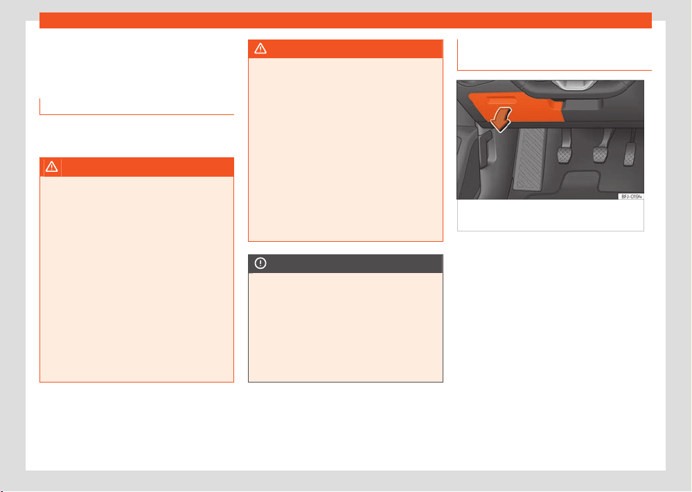
Practical equipment
235
Storage compartment
Practical equipment
St
orage compartment
Introduction
Use the storage compartments only for small or
light items.
WARNING
Objects inside the vehicle that are not se-
cur
ed could be thrown across the cabin in
the event of sudden braking or manoeuvring.
This may cause severe injuries as well as loss
of control of the vehicle.
●
Do not carry animals or sharp, hard or
heavy items in open storage compartments
of the vehicle, on the dashboard or on the
cover behind the rear seats, or inside pieces
of clothing or bags inside the vehicle.
●
Keep the storage compartments closed at
all times while the vehicle is in motion.
●
Do not hang garments weighing more than
2.5 kg (approx. 5.5 lb) on the vehicle’s coat
hooks. Never leave heavy, hard or sharp ob-
jects in the pockets of these pieces of cloth-
ing.
WARNING
If you leave lighters inside the vehicle, they
might be damaged or lit inadv
ertently. This
could lead to severe burns and damage to
the vehicle.
●
Before moving a seat, make sure there are
no lighters in the moving part area of the ve-
hicle.
●
Before closing a storage compartment,
make sure there are no lighters in the closing
area.
●
Never leave a lighter inside a storage com-
partment or any other surface of the vehicle
as it could ignite due to the high tempera-
tures on such surfaces, particularly during
the summer.
NOTICE
●
Do not store heat- or cold-sensitive ob-
jects, f
ood or medicines in the cabin. Heat
and cold could damage them or render them
useless.
●
Objects made from transparent materials
left inside the vehicle, such as glasses, mag-
nifying glasses or transparent suction pads
stuck to the windows can concentrate sun-
light and damage the vehicle.
storage compartment on the driver's
side
Fig.175 On the driv
er side: storage
compartment.
Opening: Pull the handl
e ›››Fig.175.
Closing: Press the cover upwards until it clicks
into place.
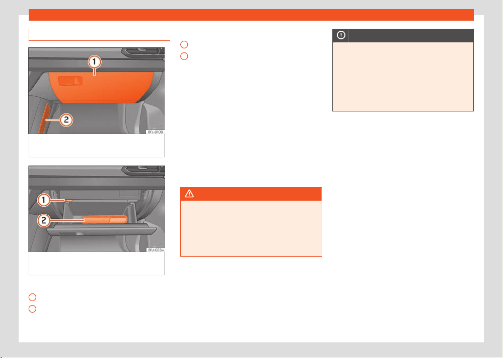
236
Practical equipment
1
2
1
2
Glove compartment
Fig.176 On the passenger side: gl
ove
compartment.
Fig.177 On the passenger side: gl
ove
compartment open.
Key to ›››Fig.1
76
Glove compartment
Storage net
Key to ›››Fig.1
77
Air diuser regulator
On-board documentation
Opening and closing the glove compart-
ment
Opening: Pull the handle ›››Fig.176 and open
the glove compartment.
Closing: Press the glove compartment up-
wards.
Glove compartment cooling
With the AC on, cool air can be directed to-
wards the inside of the compartment. Turn the
air vent to open and close it.
WARNING
If the glove compartment is left open, the risk
of causing se
vere injuries in the event of an
accident, sudden braking or manoeuvring in-
creases.
●
Always keep the glove compartment
closed while the vehicle is in motion.
NOTICE
For structural reasons, some vehicle versions
will hav
e gaps behind the glove compart-
ment (for instance, behind the compartment
for on-board documentation) into which
small objects may fall. This could lead to
strange noises and damage to the vehicle.
You should therefore not keep very small ob-
jects in the glove compartment.
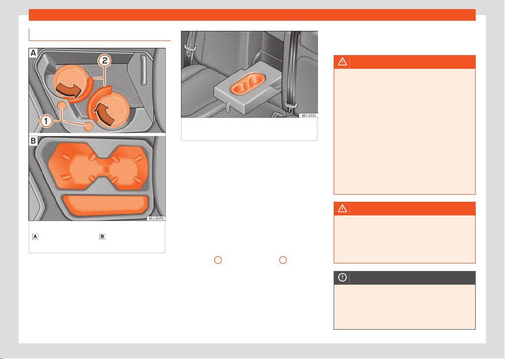
Practical equipment
237
Storage compartment
Drink holder
Fig.178 In the fr
ont part of the centre console:
cup holder (variant 1); cup holder (variant
2).
Fig.179 In the r
ear central armrest: drink
holder.
The storage compartments of the driver and
passenger doors cont
ain a bottle holder.
Depending on the equipment, there are two
drink holders in the front part of the centre con-
sole ›››Fig.178.
Drinks holder (variant 1).
Opening: Move the lid backwards.
Closing: Move the lid forwards.
To adapt the drink holder to the size of
the container, press the corresponding button
›››Fig.178
1
. The securing ring
2
opens.
When you ar
e not using the drink holder any
more, press the corresponding ring 2 in the op-
posite direction to the arrow until it locks.
Drinks holder in the rear central armrest
Use: Lower the central armrest ›››Fig.178.
When the drink holder is no longer in use, lift the
armrest again.
WARNING
Incorrect use of the bottle holders may
cause injuries.
●
Never put hot drinks in the drink holders.
In the e
vent of sudden braking or an acci-
dent while driving, hot beverages in the bot-
tle holders might spill and cause burns.
●
Ensure that no bottles or other objects are
dropped in the driver footwell while driving,
as they could get under the pedals and ob-
struct their working.
●
Never place glasses, food or other heavy
objects drink holders. These heavy objects
may be thrown across the cabin in the event
of an accident and cause serious injuries.
WARNING
Closed bottles may explode inside the vehi-
cl
e due to cold or heat.
●
Never leave closed bottles in the vehicle
if the temperature inside is very high or very
low.
NOTICE
Do not leave open cans in the drink holders
when the vehicle is in motion. If the drink is
spilled (e.g. due to sudden braking) it may
damage the vehicle and its electrical sys-
tem.
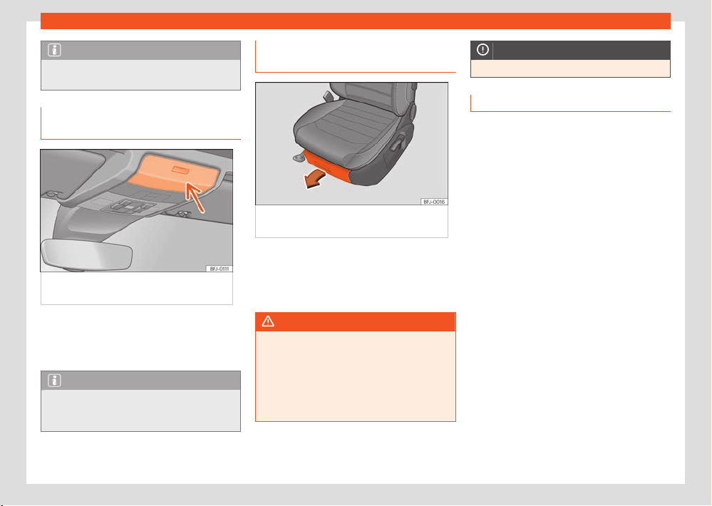
238
Practical equipment
Note
The inside elements of the drink holders can
be e
xtracted for cleaning.
Storage compartment in the roof
console (glasses case)
Fig.180 On the r
oof console: compartment for
glasses.
Opening: Pr
ess and release the button
›››Fig.180.
Closing: Press the cover upwards until it clicks
into place.
Note
For the interior monitoring to work correctly,
the st
orage compartments must be closed
when locking the vehicle.
Storage compartment under front
seats
Fig.181 St
orage compartment under the right
front passenger seat.
Opening: Pr
ess the tab on the drawer handle
and take the drawer out.
Closing: Push the drawer under the seat until it
engages.
WARNING
If the drawer is left open, it could prevent use
of the pedal
s. This may cause serious acci-
dents and injuries.
●
Always keep the drawer closed while the
vehicle is in motion. Otherwise, the drawer
and any objects in it could fall into the driv-
er's footwell and obstruct the pedals.
NOTICE
The drawer can contain 1.5 kg at most.
Other object holders
Y
ou will find more object holders, compart-
ments and supports in other parts of the vehi-
cle:
●
In the centre console.
●
In the front central armrest.
●
Other storage compartments are found in the
r
ear seat, to the left and the right of the seats.
●
In the backrests of the front seats, storage
pockets.
The Apple® iPod adapter or the USB port may
be housed in the storage compartment of the
front centre armrest.
There are hangers on the struts of the doors
and the rear.
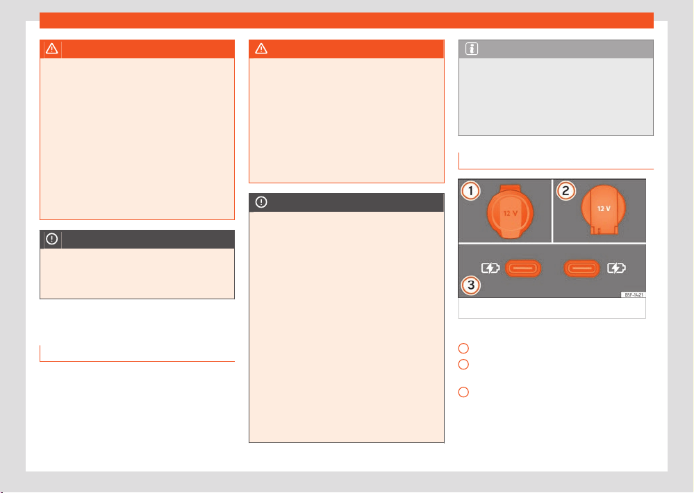
Practical equipment
239
Power sockets
1
2
3
WARNING
Hanging clothes may decrease the driver's
visibilit
y, which may cause serious accidents
and injuries.
●
Always hang clothes from hangers in such
a way that the driver's visibility is not aec-
ted.
●
Only hang light pieces of clothing from the
hangers of the vehicle. Never leave heavy,
hard or sharp objects in the pockets of these
pieces of clothing.
●
Do not use clothes hangers to hang up the
clothing, as this could interfere with the func-
tion of the head-protection airbags.
NOTICE
Do not place overly large objects in the
pock
ets on the front seat backrests (e.g. bot-
tles) or objects with sharp edges. Risk of
damage to the pockets and the upholstery.
Power sockets
Introduction
Electrical equipment can be plugged in to the
vehicle's sockets.
The devices must be in a perfect state of repair.
Do not use defective devices.
The 12 volt power socket will only work with the
ignition on.
WARNING
Improper use of the sockets or electrical de-
vices coul
d lead to a fire and cause serious
injuries.
●
Please ensure that children are never left
unsupervised inside the vehicle. The sockets
and the devices connected to them can be
used when the ignition is switched on.
●
If electrical devices overheat, switch them
o immediately and disconnect them from
the mains.
NOTICE
●
To avoid damaging the electrical system,
ne
ver connect electrical devices that sup-
ply power, such as solar panels or battery
chargers, to 12-volt sockets to charge the 12-
volt battery.
●
Only use electrical devices that comply
with the applicable electromagnetic com-
patibility directives.
●
To prevent voltage fluctuations from caus-
ing damage, unplug any connected electri-
cal devices before switching the ignition on
and o.
●
Never connect electrical devices that con-
sume more than the specified power to a 12
volt socket. Exceeding the maximum power
consumption could damage the vehicle's
electrical system.
●
Observe the instruction manuals of electri-
cal devices!
Note
●
The use of electrical appliances with the
engine s
witched o will cause the 12-volt
battery to discharge.
●
Uninsulated devices can interfere with the
r
adio, infotainment system and the vehicle’s
electronic system.
Vehicle power sockets
Fig.182 V
ehicle 12 volt socket.
›››Fig.182
12-volt sockets on the centre console.
12-v
olt sockets in the luggage compart-
ment.
12-volt USB sockets at the rear of the con-
sole, between the front seats.
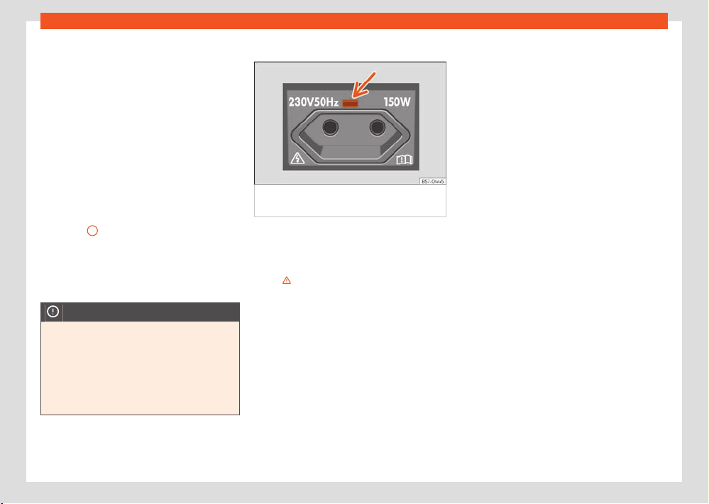
240
Practical equipment
Make sure that the maximum power of the
sock
ets is not exceeded. The power consump-
tion of the devices is shown on the type plate of
the devices.
The continuous output of all of the vehicle’s 12-
volt sockets is 120 watts in total.
When connecting two or more electrical devi-
ces at the same time, make sure that their total
consumption never exceeds 190 watts.
USB power sockets
Depending on the equipment and the country,
the vehicle may also have USB connections ex-
clusively for charging or as a power socket
›››Fig.182
3
.
These USB ports ar
e located at the rear of the
console, between the front seats . These con-
nectors can work at a maximum power of up to
10.5W per port.
NOTICE
If the 12-volt socket is used at full power for
l
onger than the specified time, the fuse may
blow.
●
Never use the 12 volt socket at full power
for more than 10 minutes.
●
In the case of full power, use a single 12-
volt socket.
230 volt power socket
Fig.183 In the l
eft hand side of the luggage
compartment: 230 volt power socket.
With the engine running, the power socket acti-
v
ates automatically as soon as a connector is
plugged in. If there is enough power available,
the socket can still be used while the engine is
o ›››
.
Maximum po
wer consumption is 150 watts (300
watts - maximum 2 minutes).
Connect an electrical device: Open the cover
and insert the plug into the power socket as far
as possible to unlock the built-in child lock. The
socket only supplies power once the child lock
is unlocked.
LED on the power socket ›››Fig.183 (arrow)
Steady green light:
●
The childproof lock is unlocked. The socket is
ready to operate.
Flashing green light:
●
The ignition is switched o, but there is
enough power available to continue supplying
the socket with current for a maximum of 10
minutes. If the connector is unplugged before
this time elapses, the socket is disconnected
and cannot be used again until the ignition is
switched on again.
Flashing red light:
●
There is an anomaly, e.g. disconnection due
to a current surge or overheating.
Disconnection due to overheating
When the temperature exceeds a certain value,
the 230 volt socket inverter is automatically dis-
connected. The disconnection prevents over-
heating when the power consumption of the
connected devices is excessive or the ambient
temperature is very high. The 230-volt power
supply can be used once again after a cool-
ing time. First unplug the connector of the con-
nected device and then plug it back in again.
This prevents the electrical device from being
switched on again if this is not wanted.
Practical equipment
241
Power sockets
WARNING
The electrical system is under high voltage!
●
Do not spill liquids onto the socket.
●
Do not plug adapters or extension cords
int
o the 230 volt power socket. Otherwise,
the integrated child lock will be unlocked
and the power socket will operate.
●
Do not insert conductive objects (a knitting
needle, for example) into the 230 volt power
socket.
NOTICE
230 volt power socket:
●
Do not leave devices or connectors that
ar
e too heavy (e.g. a transformer) hanging
directly from the power socket.
●
Do not connect neon lamps.
●
Only connect devices to the socket if the
device and socket voltage match.
●
The built-in overload disconnect function
prevents any electrical devices that require
a high start-up current from turning on. In this
case, unplug the electrical device's power
supply and re-try the connection after about
10 seconds.
Note
Some appliances may not work properly
when connected to the 230 volt sockets due
to a lack of power (watts).
242
Data transmissions
Data transmissions
SEAT CONNEC
T
Introduction
To use it, SEAT CONNECT must first be activa-
ted online by entering into a SEAT CONNECT
contract with SEAT, S.A. and is subject to a tem-
porary use limitation depending on the country.
Both the SEAT CONNECT service portfolios of-
fered by SEAT and individual services can be
modified, cancelled, deactivated, reactivated,
renamed and extended, even without prior noti-
fication.
In https://my.seat you can create the user ac-
count, see the description of services and more
information.
The execution and availability of the SEAT
CONNECT services and service portfolios may
vary depending on the country, as well as the
vehicle, its equipment and connectivity.
SEAT CONNECT's voice recognition or search
technology does not recognise or oer results
for all words.
There are SEAT CONNECT services for which
registration is mandatory and others for which it
is not mandatory.
Description of services
Before running SEAT CONNECT services, read
and take into account the description of the
corresponding services. Descriptions are upda-
ted non-periodically and are available online at
https://my.seat.
●
Always use the most up-to-date version of
the corresponding service description.
WARNING
In areas with insucient mobil
e phone and
GPS coverage, emergency calls and phone
calls will not be connected and data cannot
be transmitted.
●
Change location if possible.
NOTICE
The vehicle may be damaged by factors out-
side the contr
ol of SEAT, S.A. These damaged
can include:
●
Misuse of mobile terminals
●
Data loss during transmission.
●
Unsuitable or defective third party appli-
cations.
●
Malicious software on data storage devi-
ces, computers, tablets or mobile phones.
Services portfolio
The initial service assignment sho
wn here rep-
resents the maximum possible volume. The
maximum possible volume is only available on
a few vehicle models. During the useful life of
the vehicle, you can change the assignment
shown here.
After activating the service management in the
infotainment system, you can check whether
services are available to the vehicle and what
services they are ›››page246.
In some countries and in the event of a contract
renewal, the services oered may be combined
dierently than indicated here. They may also
vary depending on the year of production of
the vehicle. The services mentioned correspond
to SEAT CONNECT Gen3 (third generation).
SEAT CONNECT services and functions that
do not require activation
The following services also work without the
activation of SEAT CONNECT:
●
Public emergency call service.
●
Privacy mode.
●
Legal.
SEAT CONNECT services
The SEAT CONNECT services are:
●
Private emergency call
●
Public emergency call

Data transmissions
243
SEAT CONNECT
●
Roadside assistance call
●
Customer support
●
Service appointment planning
●
Online system update
●
Customisation
●
Activating SEAT CONNECT
●
Private mode (deactivation of services)
●
Delete user / Reset factory settings
●
Remote independent heating
●
Remote opening
●
Horn and turn signals
●
Vehicle status incl. doors and lights
●
Driving data
●
Vehicle status report
●
Anti-theft alarm warning
●
Zone warning
●
Speed warning
●
Online map update
●
Search for points of interest
●
Petrol stations
●
Online tr
ac information
●
Parking lots
●
Online infotainment system update
●
Online route calculation
●
Information on risks
●
Dictation
●
Online radio
●
Online media
●
Online route import
●
Online destination import
●
Remote auxiliary ventilation
●
Parking position
●
Privacy mode
●
Legal
SEAT CONNECT services for hybrid vehicles
Available only in electric and hybrid vehicles.
The included services are all the SEAT CON-
NECT services in the previous section plus:
●
Remote air conditioning
●
Electrical power manager
●
Departure times
SEAT CONNECT individual options
●
In-Car Applications. These applications can
be purchased and installed directly in the info-
tainment system through the In-Car store.
●
Full Link.
●
Data package. Pay per use data rates for the
use of online functions, for example, 2 GB per
month.
Note
●
The public emergency call service is avail-
abl
e regardless of whether the infotainment
system is logged in.
●
Customisation and purchase of In-Car ap-
plications r
equire logging into infotainment
system, but the activation of the vehicle in a
SEAT CONNECT account is not necessary.
Activation of SEAT CONNECT and S-
PIN
The following steps are necessary for the ac-
tivation of SEAT CONNECT (including registra-
tion):
●
Create a user account at https://my.seat or
dir
ectly through the infotainment system in the
User Management menu.
●
Place the SEAT CONNECT order and activate
it.
●
Add the vehicle to your user account.
●
Prove ownership.
●
Prove your identity. It is only necessary if you
are to run SEAT CONNECT services relevant to
security.
●
You can activate it at https://my.seat or di-
rectly through the infotainment system. To ac-
tivate it through the infotainment system, pro-
ceed as follows:
9.2” HOME > Manage users > Become
primary user.
244
Data transmissions
8.25” MENU > Settings > SEAT Connect
> Register.
F
ollow the rest of the indications and the infor-
mation shown in the infotainment system. Dur-
ing activation, you may be asked to create an
S-PIN.
Update option
9.2” Infotainment yes
8.25” Infotainment yes
SEAT CONNECT portal yes
SEAT CONNECT application yes
More information at https://my.seat/faqs
S-PIN
The S-PIN is a sequence of se
veral digits, which
can be selected when completed the SEAT
CONNECT registration.
When creating the S-PIN, avoid easy-to-guess
number sequences and known dates of birth.
You can change the S-PIN in the SEAT CON-
NECT user account in “Account settings”.
The S-PIN is necessary, for example, to protect
your user profile or to run a SEAT CONNECT
service relevant to the security of your vehicle.
You must manage this S-PIN with absolute con-
fidentiality.
If you reveal the S-PIN to third parties, for secur-
ity reasons you must change it immediately.
Ownership and identity accredita-
tion
Depending on the Inf
otainment system, the
ownership accreditation method will be the 2-
key method or the registration code method.
9.2” Infotainment system
To become a main user and thus prove own-
ership of the vehicle, you need both of the ve-
hicle’s physical keys. Ownership accreditation
takes place in the vehicle during registration or,
if you already have a SEAT CONNECT user ac-
count, you must log in through the infotainment
system and then go to User management.
●
Switch on the ignition and the infotainment
syst
em.
●
In the infotainment system, register in SEAT
CONNECT.
●
Or: open the menu Manage users > Settings
> Become primary user and follow the instruc-
tions.
●
Press the unlock button on the first vehicle
key.
●
Press the unlock button on the second vehi-
cle key.
8.25” Infotainment system
To become the main user and therefore ac-
credit ownership of the vehicle, you will need
the registration code found on the SEAT website
and in the APP after linking the vehicle to your
account (My Garage > Add Vehicle > Accept
terms and conditions and SEAT privacy pol-
icy). Ownership is accredited inside the vehicle.
Go to Vehicle settings > SEAT CONNECT >
Registration and enter the pairing code shown
on the website or in the App.
Once the infotainment system has processed
the orders by radiofrequency, the accreditation
of the ownership will have been completed. You
can control the current status in the SEAT CON-
NECT portal.
How is ownership accredited?
9.2” Infotainment 2-Key method.
8.25” Infotainment Pairing code.
SEAT CONNECT portal No, it is not possible
SEAT CONNECT appli-
cation
No, it is not possible
Identity accreditation (SEAT Ident)
Identity accreditation must be done before you
can use SEAT CONNECT services that are rele-
vant to security, such as the “Remote Opening”
service. Identity accreditation can be done in
two ways:
●
In person at the SEAT dealership.
●
You can find more information about SEAT
Ident on the SEAT CONNECT portal at https://
my.seat.

Data transmissions
245
SEAT CONNECT
Legal provisions
During the use of SEAT CONNEC
T services, in-
formation is transferred and processed online
through the vehicle. Such data can also provide
(at least indirectly) information about the driver
in question, for example, driving behaviour and
location. As a contracting party in the SEAT
CONNECT contract with SEAT, S.A., you must
ensure that when your vehicle is used by other
drivers (for example, family or friends), data
protection and personal rights are respected.
Therefore, you must inform drivers in advance
that the vehicle transfers and receives data on-
line, and that you can access such data.
Not taking into account this obligation to inform,
can infringe certain rights of the occupants.
Users can manage data sending and transfers
through the privacy mode at any time. More
information at: https://my.seat/faq.
Follow-up services: ask all occupants
The follow-up services need geographical and
vehicle data to determine whether the vehicle is
being used within defined speed ranges, where
it has been parked or if it is being used in an es-
tablished geographical area. This information is
displayed on the SEAT CONNECT portal and in
the SEAT CONNECT app.
Therefore, before moving o, ask all the vehi-
cle occupants if they agree with the activated
services. If they do not, deactivate the service in
question (if possible) or do not allow the occu-
pants to use the vehicle.
GPS tracking: marking
If the vehicle has a factory-assembled control
unit that transmits the its current geographical
position and speed, the vehicle usually has this
GPS marking (e.g., on the roof console). The
absence of the marking on the vehicle does not
guarantee that the control unit does not trans-
mit the vehicle’s current geographical position
and speed.
Personal information
SEAT protects your personal data and only
uses them, as long as the law allows it or you
have given your consent on the occasion of a
use. You will find detailed information on data
processing in relation to SEAT CONNECT serv-
ices in the Privacy Policy, which you can ac-
cess in its corresponding current version on the
SEAT website.
Permanent transfer of the vehicle
If another person has left you the vehicle for
permanent use (for example, if you buy a used
vehicle), SEAT CONNECT may already be acti-
vated and the previous user still has the possi-
bility of accessing the data registered through
SEAT CONNECT and control certain functions
of your vehicle.
In the infotainment system you can check if
your vehicle is assigned to a person as the
main user. In this case, you can register yourself
as the main user of the vehicle and thus auto-
matically delete the previous main user. Alter-
natively, through the infotainment system you
can directly and permanently delete the previ-
ous user as the main user, as well as put the
vehicle in oine mode and thus limit both the
communication of your vehicle with the SEAT,
S.A. data server and the processing of personal
and vehicle data.
Deactivating SEAT CONNECT serv-
ices
The following functions are available to acti-
vate and deactivate the SEAT CONNECT serv-
ices:
●
Allow or prevent data transmissions through
the inf
otainment system ›››page246, Privacy
mode.
●
Whenever possible: individual deactivation or
activation ›››page246.
You can run the relevant services again after
cancelling their deactivation.
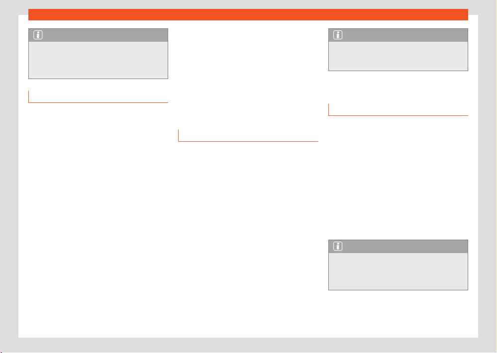
246
Data transmissions
Note
The services required by law and their data
tr
ansmission cannot be disconnected or de-
activated, for example, the emergency call
system (eCall).
Faults
Even if the prerequisites for the use of SEAT
CONNECT services are met, there may be fac-
tors beyond the control of SEAT, S.A. that inter-
fere with the execution of such services or pre-
vent them. These may be specifically:
●
Maintenance, repair, deactivation, software
update and technical expansion of telecommu-
nication equipment, satellites, servers and data
banks.
●
Change of the mobile telephony standard
for the transmission of mobile data by the tele-
communications service provider, for example,
from UMTS to EDGE or GPRS.
●
Disconnection of an existing mobile phone
standard by the telecommunications service
provider.
●
Interference, disturbance or interruption in
the reception of the mobile phone and GPS sig-
nal due to aspects such as high-speed driving,
solar storms, meteorological influences, topog-
raphy, blocking equipment and the intensive
use of mobile phones in the radio cells in ques-
tion.
●
When in areas with zero or insucient mobil
e
telephony or GPS signal. Also, for example, in
tunnels, confined areas between very tall build-
ings, garages, underpasses, mountains and val-
leys.
●
External information from third party supplies
available with limitations, incomplete or incor-
rect, e.g. representations of maps.
●
Countries and regions where SEAT CONNECT
is not oered.
Service management
Open the settings in Users and go to Privacy
settings and services. In vehicles fitted with
the 9.2” Infotainment, it is accessed from Users
> Settings > Private Mode (deactivation of
services). In vehicles equipped with the 8.25”
Infotainment it is accessed from Settings >
SEAT Connect > Privacy settings and serv-
ices. You can do the following in the infotain-
ment system:
●
Check which SEAT CONNECT services are
currently available in the vehicle.
●
The number of SEAT CONNECT services that
are enabled or disabled.
●
Activate or deactivate SEAT CONNECT serv-
ices.
More information at https://my.seat.
Note
If you deactivate all SEAT CONNECT serv-
ices, the v
ehicle can still transmit emergency
call (eCall) data.
Privacy mode
Introduction
With the “Privacy” function, data transmissions
between the vehicle and the Internet can be
allowed or blocked.
The desired mode can be set in vehicle settings
in the infotainment system.
Data transmission by external devices and their
communication with the vehicle cannot be
blocked using the “Privacy” function.
The services required by law and their data
transmission cannot be disconnected or deac-
tivated, for example, the emergency call system
(eCall).
Note
Please note that all vehicle users can config-
ure individual settings in the “Privacy” func-
tion. These settings may not match those de-
sired by the vehicle owner.
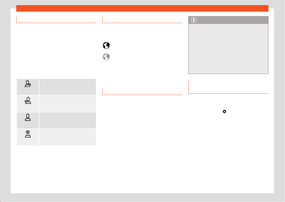
Data transmissions
247
WLAN access point
no icon
Privacy and services settings
SEAT CONNEC
T services can be activated and
deactivated individually. To do this, just check
the box corresponding to the service you want
to activate or deactivate. Use the privacy mode
option if you want to deactivate all of the serv-
ices at the same time.
Privacy mode
Allows you to deactivate or activate the serv-
ices depending on the selected privacy level.
Tracking
Share location. Main users and
co-users can vie
w position data on
the SEAT CONNECT portal or app.
Location
Use location. P
osition, vehicle,
and user data are used for services.
Personal
No location. Only the v
ehicle
data and user data are used for
services.
Incognito
Maximum privacy. Y
our serv-
ices are disabled. Only services re-
quired for legal reasons use data.
Setting options are not available in all markets
or in all v
ehicle models.
Connectivity status indication
The following symbols indicate the respective
data transmission status in the infotainment
system.
Symbol white: full connectivity, all serv-
ices active
Symbol grey: limited connectivity, some
services may not be available.
No connectivity, no services available.
WLAN access point
Intr
oduction
✓ Not available on vehicles without SEAT CONNECT
and without navigation
The infotainment system can be used to share
a WLAN connection with up to 8 devices
›››page247, Configuration for sharing a con-
nection over WLAN.
The infotainment system can also use the WLAN
hotspot of an external device to provide Inter-
net to the devices connected to the hotspot
(WLAN client) ›››page248.
Note
●
Data transmission may incur charges. Due
t
o the high volume of data exchanged, SEAT
recommends the use of a flat rate tari for
data transmission. Mobile phone operators
can provide the relevant information.
●
Exchanging data packages and purchas-
ing them from third parties may generate
additional costs, depending on your mobile
phone rate, particularly if you are abroad
(for example, roaming rates).
Configuration for sharing a connec-
tion over WLAN
Establishing the connection with the wire-
less network (WLAN)
●
Press the HOME >
button.
●
Activate the wireless network. To do this, press
the function butt
on Wi-Fi > Infotainment sys-
tem as hotspot.
●
Activate the wireless network (WLAN) on the
device that is to be connected. If necessary,
refer to the manufacturer’s instruction manual.
●
Activate the mobile device assignment in the
infotainment system. To do this, press the func-
tion button Use as hotspot and check the
checkbox.
●
Enter and confirm the network key displayed
on the device.
248
Data transmissions
The following adjustments can also be made in
the Inf
otainment system as hotspot menu:
●
Security level: WPA2 encryption automati-
cally generates a network key.
●
Network key: Network key automatically
generated. Press the function button to man-
ually change the network key. The network key
must have a minimum of 8 characters and a
maximum of 63.
●
SSID: WLAN Network name (maximum of 32
characters).
The wireless (WLAN) connection is established.
To complete the connection, it may be neces-
sary to enter other data into the device.
Depending on the version, it is only possible to
connect in Hotspot mode to get AppConnect,
and a maximum of 5 devices can be connec-
ted.
Repeat this process to connect other devices.
There is also the option of scanning the QR
code by connecting the device directly to the
infotainment system’s Wi-Fi network without
having to enter the password: select Settings
> Wi-Fi > Quick connection to infotainment
system.
An additional feature is that the infotainment
system can provide data to any device over
WPS (Hotspot mode) in the same menu as the
QR code.
Wi-Fi Protected Setup (WPS)
✓ This depends on the equipment and the country
in question.
Wi-Fi Pr
otected Setup allows an encoded local
wireless network to be created quickly and sim-
ply (Settings > Wi-Fi > Wi-Fi > Quick
WPS connection).
●
Establish the connection with the wireless
netw
ork (WLAN).
●
Press the WPS button on the WLAN router un-
til the warning light on the router starts flashing.
If the WLAN router does not support WPS the
network must be configured manually.
●
OR: Press and hold the WLAN button on the
WLAN router until the WLAN light on the router
starts flashing.
●
Press the WPS button on the WLAN device.
The wireless (WLAN) connection is established.
Repeat this process to connect other devices.
Configure Internet access
The infotainment system can use the WLAN hot-
spot of an external device to establish an Inter-
net connection.
Establishing the connection with the wire-
less network (WLAN)
●
Activate and share a wireless hotspot with In-
t
ernet on the external device. Refer to the man-
ufacturer’s instruction manual.
●
Press the HOME >
button.
●
Press the Wi-Fi > Connect t
o Wi-Fi menu and
put a check in the checkbox.
●
Press the Search for Wi-Fi button and select
the device you want from the list.
●
If necessary, enter the network key of the
device in the infotainment system and confirm
with OK.
Manual settings:
●
To manually enter the network settings of an
external (WLAN) device.
The wireless (WLAN) connection is established.
To complete the connection, it may be neces-
sary to enter other data into the device.
Note
Due to the large number of devices on the
mark
et, it is not possible to guarantee fault-
free operation of all functions.
Full Link
Introduction
With Full Link it is possible to view and use
the contents and functions that are shown on
the mobile phone device on the infotainment
screen.
Data transmissions
249
Full Link
To do this, the mobile phone device must
be connect
ed with the infotainment system
through a USB interface.
Some technologies can also be used by Wire-
less Full Link through the Bluetooth® interface
and a Wi-Fi connection.
The following technologies may be availa-
ble:
●
Apple CarPlay™
●
Apple CarPlay™ Wireless
●
Android Auto™
●
Android Auto™ Wireless
●
MirrorLink®
The availability of the technologies that Full Link
includes depends on the country and the mo-
bile phone device used.
You will find more information on the SEAT web-
site (www.seat.com).
Access the Full Link main menu
Browsing the Full Link main menu depends on
the infotainment system used.
●
Press Home > Full Link
Configure Wireless Full Link
In order to use Wireless Full Link, you must first
pair the mobile phone device with the infotain-
ment system. To do this, proceed as follows:
Connect a mobile phone device for the first
time.
●
Unlock the mobile phone device.
●
Enable Wi-Fi reception and Bluetooth® on the
mobile phone device.
●
Connect the mobile phone device to the info-
tainment system using a USB cable or via Blue-
tooth®.
●
Access the Full Link main menu, if it is not
displayed automatically.
●
Select the mobile phone device and the
t
echnology you want.
●
Confirm authorisation inquiries on the mobile
phone device to grant the necessary authorisa-
tions to the infotainment system.
●
Disconnect the USB connection and connect
with the infotainment system again via Wi-Fi or
Bluetooth®. Wireless Full Link is now configured.
The pairing has concluded. The connected mo-
bile phone device can also use Wireless Full
Link from now on without the USB connection.
If pop-up menus are rejected during the con-
nection process, Wireless Full Link will not be
available. In this case, SEAT recommends delet-
ing the devices in both the telephone settings
and the infotainment system, and restarting the
connection process.
WARNING
The use of applications while driving can dis-
tr
act your attention from the trac. Any dis-
traction aecting the driver in any way can
lead to an accident and cause injuries.
●
Always drive as carefully and responsibly
as possible.
WARNING
Any applications that are not suitable or ex-
ecut
e incorrectly may cause damage to the
vehicle, accidents and serious injuries.
●
Protect the mobile phone device and its
applications from inappropriate use.
●
Never carry out modifications to the appli-
cations.
●
Follow instructions in the instruction man-
ual for the mobile phone device.
NOTICE
SEAT cannot be held liable for any damage
caused to the vehicle as a result of the use
of applications that are of poor quality or
are defective, the inadequate programming
of the applications, the insucient coverage
of the network, the loss of data during trans-
mission or the improper use of mobile phone
devices.
250
Data transmissions
Note
●
Wireless Full Link may not be compatible
with all t
echnologies.
●
When crossing the border into countries
with permitted radio frequencies dierent to
those in your own country, running the Full
Link Wireless function may be restricted or
even unavailable due to legal regulations.
This can also be indicated by a message in
the infotainment system. Running Full Link via
cable is not aected by this restriction and
can continue to be used.
Applications (apps)
With SEAT Full Link, the display of the contents
of SEAT applications and other providers instal-
led on mobile phone devices can be transferred
to the infotainment screen.
In the case of third-party applications, there
may be compatibility problems.
Applications, their use and the necessary mo-
bile phone connection may be pay per use.
The oer of applications can be varied and de-
signed for a vehicle or a specific country. The
content and volume of applications, as well as
the companies that oer them, may vary. Some
applications also depend on the availability of
third-party services.
It cannot be guaranteed that all the applica-
tions oered will work on all mobile phone devi-
ces or with all their operating systems.
The applications oered by SEAT can be modi-
fied, cancelled, deactivated, reactivated and
extended without prior notification.
To avoid distracting the driver while driving, only
certified applications can be used.
Full Link symbols and settings
To show more information.
T
o open the Full Link settings menu
To select Apple CarPlay technology.
To select Android Auto™ technology.
To select MirrorLink® technology.
Apple CarPlay™
In order to use Apple CarPlay, the following re-
quirements must be met:
●
The iPhone™ must be compatible with Apple
CarPlay™.
●
Voice control (Siri ™) must be active on the
iPhone™.
●
Apple CarPlay™ must be active without limi-
tations in the iPhone™ settings.
●
If this is not possible via Apple CarPlay™ Wire-
less, the iPhone™ must be connected to the
infotainment system via a USB connection. Only
USB connections with data transmission are
suitable for the use of Apple CarPlay™.
●
The USB cable used must be an original Ap-
pl
e™ cable.
Apple CarPlay™ Wireless: Bluet
ooth® and Wi-Fi
must also be activated on the iPhone™.
Establish connection
When you first connect an iPhone™, follow the
instructions on the infotainment system screen
and on the iPhone ™.
The requirements must be met to use Apple
CarPlay™.
Launch Apple CarPlay™:
●
Press HOME > Full Link to access the Full
Link main menu.
●
Press Apple CarPlay™ to establish a connec-
tion with the iPhone™.
Disconnecting
●
In Apple CarPlayTM mode, press the SEAT
icon t
o access the Full Link main menu.
●
Press
to interrupt the active connection.
The r
epresentation of function buttons on the
screen may vary.
Special characteristics
During an active Apple CarPlay™ connection,
the following characteristics are applicable:
●
Bluetooth® connections between the
iPhone™ and the infotainment system are not
possible.
●
If there is an active Bluetooth® connection, it
is automatically interrupted.
Data transmissions
251
Full Link
●
The phone functions are only available
thr
ough Apple CarPlay™. The functions descri-
bed for the Infotainment system are not availa-
ble.
●
The connected iPhone™ cannot be used as
a media device in the Media main menu.
●
It is not possibl
e to use the built-in naviga-
tion system and the Apple CarPlay™ navigation
system at the same time. The last route started
interrupts the one that was previously active.
●
Depending on the infotainment system you
use, on the instrument panel screen you can
view data from the Telephone mode.
●
Depending on the infotainment system you
use, on the instrument panel screen you can
view data from the Media mode.
●
The instrument panel screen does not display
any indication to turn.
●
With the multifunction steering wheel you can
accept or reject incoming calls, as well as end
an ongoing telephone conversation.
Voice control
●
Press
briefly t
o start voice control using
the infotainment system.
●
Press this button for a long time to start voice
control (Siri™) of the connected iPhone™.
Note
●
The availability of technologies depends
on the country and may v
ary.
●
You will find information about technical
requirements, compatible iPhones, certified
applications and their availability on the
SEAT (www.seat.com) and Apple CarPlay ™
websites, or at SEAT dealerships.
Android Auto™
Requirements for Android Auto™
In order to use Android Auto™, the following re-
quirements must be met:
●
The mobile phone device, called smartphone
from here on, must be compatible with Android
Auto™.
●
The smartphone must have an Android Auto™
application installed.
●
If this is not possible via Android Auto Wireless,
the smartphone must be connected via the USB
connection with data transmission to the info-
tainment system.
●
The USB cable used must be an original ca-
ble provided by the smartphone manufacturer.
Android Auto Wireless: Bluetooth® and WLAN
(Wi-Fi) also have to be active on the smart-
phone.
Establish connection
When you first connect a smartphone, follow
the instructions on the infotainment system
screen and on the smartphone.
The requirements must be met to use Android
Auto™.
Launch Android Auto™:
●
Press HOME > Full Link to access the Full Link
main menu.
●
Press Android Auto™ to establish a connec-
tion with the smartphone.
Disconnecting
●
In Android AutoTM mode, press the SEAT /
Exit icon to access the Full Link main menu.
●
Press
to interrupt the active connection.
Special char
acteristics
During an active Android Auto™ connection, the
following characteristics are applicable:
●
An active Android Auto™ device can be con-
nected at the same time via Bluetooth® (HFP
profile) with the infotainment system.
●
It is possible to use the phone’s functions
through Android Auto™. If the Android Auto™
device is connected at the same time via Blue-
tooth® with the infotainment system, the tele-
phone function of the infotainment can also be
used.
252
Data transmissions
●
An active Android Auto™ device cannot be
used as a media de
vice in the Media main
menu.
●
It is not possibl
e to use the built-in navigation
system and the Android Auto™ navigation sys-
tem at the same time. The last route started
interrupts the one that was previously active.
●
Telephone and Media data can be displayed
on the instrument cluster screen.
●
With the multifunction steering wheel you can
accept or reject incoming calls, as well as end
an ongoing telephone conversation.
Voice control
●
Press
briefly t
o start voice control using
the infotainment system.
●
Press and hold this button to start voice con-
trol (Google Assistant) on the connected smart-
phone.
Note
●
The availability of technologies depends
on the country and may v
ary.
●
You will find information about technical
requirements, compatible mobile phone de-
vices, certified applications and their avail-
ability on the SEAT (www.seat.com) and An-
droid Auto™ websites, or at SEAT dealerships.
MirrorLink®
R
equirements for MirrorLink®
In order to use MirrorLink®, the following re-
quirements must be met:
●
The mobile device must be compatible with
MirrorLink®.
●
The mobile phone device must be connec-
ted to the infotainment system via a USB con-
nection that is suitable for data transmission.
●
The USB cable used must be an original ca-
ble provided by the mobile phone device man-
ufacturer.
●
Depending on the mobile phone device used,
a Car-Mode application that is suitable for us-
ing MirrorLink® must be installed.
Establish connection
When you first connect a mobile phone device,
follow the instructions on the infotainment sys-
tem screen and on the mobile phone device.
The requirements must be met to use Mirror-
Link®.
Start MirrorLink®:
●
Press HOME > Full Link to access the
Full Link main menu.
●
Press MirrorLink t
o connect to the mobile
device.
Disconnecting
●
In MirrorLink® mode, press
APP t
o access
the Full Link main menu.
OR: press
to access the MirrorLink® main
menu.
●
Press to interrupt the active connection.
Special char
acteristics
During an active MirrorLink® connection, the
following characteristics are applicable:
●
An active MirrorLink® device can be connec-
ted to the infotainment system at the same time
via Bluetooth®.
●
If the MirrorLink® device is connected to the
infotainment system via Bluetooth®, the tele-
phone function of the infotainment system can
be used.
●
You cannot use an active MirrorLink® device
as a media device in the Media main menu.
●
On the instrument panel screen you can view
dat
a from the Telephone mode.
●
The instrument panel screen does not dis-
play any indication to turn or the Media mode.
●
With the multifunction steering wheel you can
accept or reject incoming calls, as well as end
an ongoing telephone conversation.
Function buttons
Function buttons and their function:

Data transmissions
253
Wired and wireless connections
APP Return the Full Link main menu. Here
you can end the Mirr
orLink® connection,
connect another mobile phone device or
select another technology.
Press to close the open apps. Then press
the apps to be closed or the
Close
all function butt
on to close all the open
applications.
Press to display the mobile phone device
screen on the infotainment system screen.
To open the MirrorLink® settings.
Press to return to the MirrorLink® main
menu.
Note
You will find inf
ormation about technical re-
quirements, compatible mobile phone devi-
ces, certified applications and their availa-
bility on the SEAT (www.seat.com) and Mir-
rorLink® websites, or at SEAT dealerships.
Wired and wireless connec-
tions
USB connection
Fig.184 Centr
e console: USB input.
Fig.185 R
ear centre console: USB connectors
with power socket function.
The USB port can be found in the storage
compartment ar
ea of the front centre console
›››Fig.184.
Depending on the equipment and the country,
the vehicle may also have USB connections ex-
clusively for charging or as a power socket.
These USB ports are located at the rear of the
console, between the front seats ›››Fig.185.
Note
Before switching the ignition on or o, unplug
the appliances fr
om the USB ports to protect
them from any damage caused by fluctua-
tions in voltage.
254
Infotainment system
Infotainment system
First st
eps
Introduction
Infotainment functions and settings depend on
the country and equipment.
Before first use
Before the first use, bear in mind the following
points, to take full advantage of the functions
and settings oered:
●
Observe the basic safety warnings
›››page254.
●
Reset the Infotainment factory settings.
●
Search and store favourite radio stations
on the pr
eset buttons so you can tune them
quickly.
●
Use only suitable audio sources and data me-
dia.
●
Pair a mobile phone to use phone manage-
ment through the Infotainment system.
●
Use current maps for navigation.
●
Register in SEAT CONNECT to run the corre-
sponding services.
Current documentation attached
F
or using infotainment and its components, take
into account, together with this instruction man-
ual, the following documentation:
●
Supplements to your vehicle’s on-board doc-
umentation.
●
Instruction Manual of the mobile phone de-
vice or audio sources.
●
Operating instructions for data media and ex-
ternal players.
●
Manuals for the Infotainment accessories
subsequently installed or used additionally.
●
Description of services when running SEAT
CONNECT services.
Safety instructions
Some function areas may include links to third-
party websites. SEAT, S.A. is not the owner of
the third-party websites accessible through the
links, and assumes no liability for their content.
Some function areas may include outside infor-
mation from third-party providers. SEAT, S.A. is
not responsible for such information being cor-
rect, up-to-date or complete, or for ensuring it
does not infringe the rights of third parties.
Radio stations and owners of data media and
audio sources are responsible for the informa-
tion they transmit.
Bear in mind that parking lots, tunnels, tall
buildings, mountains or due to the operation of
other electrical devices, such as chargers, can
also interfere with the reception of the radio
signal.
Foils or adhesives with metallic layers on the
antenna and on the window panes can inter-
fere with radio reception.
WARNING
The infotainment central computer is inter-
connect
ed with the control units mounted
on the vehicle. Therefore, there is a serious
danger of accident and injury if the central
computer is repaired or disassembled and
reassembled incorrectly.
●
Never replace the central computer with
another used, recycled or from another vehi-
cle at the end of its useful life.
●
The repair or disassembly and reassembly
of the central computer should only be car-
ried out at specialised workshops. SEAT rec-
ommends visiting a SEAT dealership for this.
WARNING
Any distraction aecting the driv
er in any
way can lead to an accident and cause inju-
ries. Reading the information on the screen
and managing the infotainment system can
distract your attention from trac and cause
an accident.
●
Always drive as carefully and responsibly
as possible.
Infotainment system
255
First steps
WARNING
Connecting, inserting or removing an audio
sour
ce or data media while driving can dis-
tract your attention from the trac and
cause an accident.
WARNING
Select volume settings that allow you to
easily hear signal
s from outside the vehicle
at all times (e.g. emergency services sirens).
●
Hearing may be impaired if using too high a
volume setting, even if only for short periods
of time.
WARNING
The following circumstances may result in an
emergency call, phone call or data transmis-
sion not being made or being interrupted:
●
When in areas with zero or insucient mo-
bile telephony or GPS signal. Also in tunnels,
confined areas between very tall buildings,
garages, underpasses, mountains and val-
leys.
●
When in areas with sucient mobile phone
or GPS signal, the telephony network of
the telecommunications provider has inter-
ference or is not available.
●
When the vehicle components necessary
t
o make emergency calls, phone calls and to
transmit data are damaged, do not work or
do not have sucient electrical power.
●
When the battery of the mobile phone de-
vice is discharged or its charge level is insuf-
ficient.
WARNING
In some countries and some telephone net-
w
orks it is only possible to make an emer-
gency call, if a mobile telephone device is
connected to the telephone interface of the
vehicle, inside it there is an “unlocked” SIM
card with sucient balance to make calls
and with sucient network signal coverage.
WARNING
Read and observe the operating instructions
provided by the manufacturer in question
when using mobile phone devices, data me-
dia, external devices, external audio and
multimedia sources.
WARNING
When changing or connecting an audio
or multimedia sour
ce may cause sudden
changes in the volume.
●
Lower the volume before connecting or
switching to audio or multimedia sources.
WARNING
If mobile phone and radiocommunication de-
vices ar
e used without connection to an
external antenna, the maximum electromag-
netic radiation levels inside the vehicle might
be surpassed, thus posing a risk to the health
of the driver and passengers. This is also the
case if the external antenna has not been
correctly installed.
●
Keep a distance of at least 20 centimetres
between the antennas of the mobile phone
device and an active medical device, such as
a pacemaker, as mobile phones might alter
the functioning of these devices.
●
Do not carry a mobile phone switched
on very close or directly on top of an ac-
tive medical device, for instance in a chest
pocket.
●
Immediately turn o the mobile phone if
you suspect it is causing interferences in an
active medical device or any other medical
device.
WARNING
Mobile phones, external devices and acces-
sories that ar
e loose or not properly secured
could move around the passenger compart-
ment during a sudden driving or braking ma-
noeuvre or an accident and cause damage
or injury.
●
Set mobile phone devices, external devices
and their accessories outside the airbag de-
ployment areas or store them securely.
256
Infotainment system
●
Position the connection cables of the audio
sour
ces and external devices so that they do
not interfere with the driver.
WARNING
The centre armrest may obstruct the driver's
arm mo
vements, which could cause an acci-
dent and severe injuries.
●
Keep the storage compartments of the
centre armrest closed at all times while the
vehicle is in motion.
WARNING
If the light conditions are not good and the
screen is damaged or dirty, the indications
and information displayed on the screen may
not be read or be read incorrectly.
●
The indications and information displayed
on the screen should never induce to take
any risk that compromises safety. The screen
is not a replacement for driver awareness.
WARNING
Radio stations can transmit disaster or haz-
ar
d announcements. The following condi-
tions prevent such notices from being re-
ceived or issued:
●
When in areas with zero or insucient ra-
dio signal. Also in tunnels, confined areas
between very tall buildings, garages, under-
passes, mountains and valleys.
●
When the frequency bands of the radio
st
ation have interference or are not available
in areas with sucient radio signal recep-
tion.
●
When the speakers and the vehicle com-
ponents necessary for radio reception are
damaged, do not work or do not have su-
cient electrical power.
WARNING
Switch o mobil
e phone devices in areas
with a risk of explosion!
WARNING
The driving recommendations and trac in-
dications shown on the navigation system
may dier from the current trac situation.
●
Trac signs, signalling systems, trac
regulations and local circumstances prevail
over driving recommendations and naviga-
tion system indications.
●
Adapt your speed and driving style to
suit visibility, weather, road and trac condi-
tions.
●
Certain circumstances can significantly in-
itially planned lengthen both the duration of
the trip and the route to the destination, or
even temporarily prevent navigation to it, for
example, if a road is closed to trac.
NOTICE
In areas where special regulations apply or
the use of mobil
e phones is forbidden, the
mobile device in question must be switched
o at all times. The radiation produced by a
mobile phone device when switched on may
interfere with sensitive technical and medi-
cal equipment, possibly resulting in malfunc-
tion or damage to the equipment.
NOTICE
If the playback volume is excessive or distor-
t
ed, the speakers may be damaged.
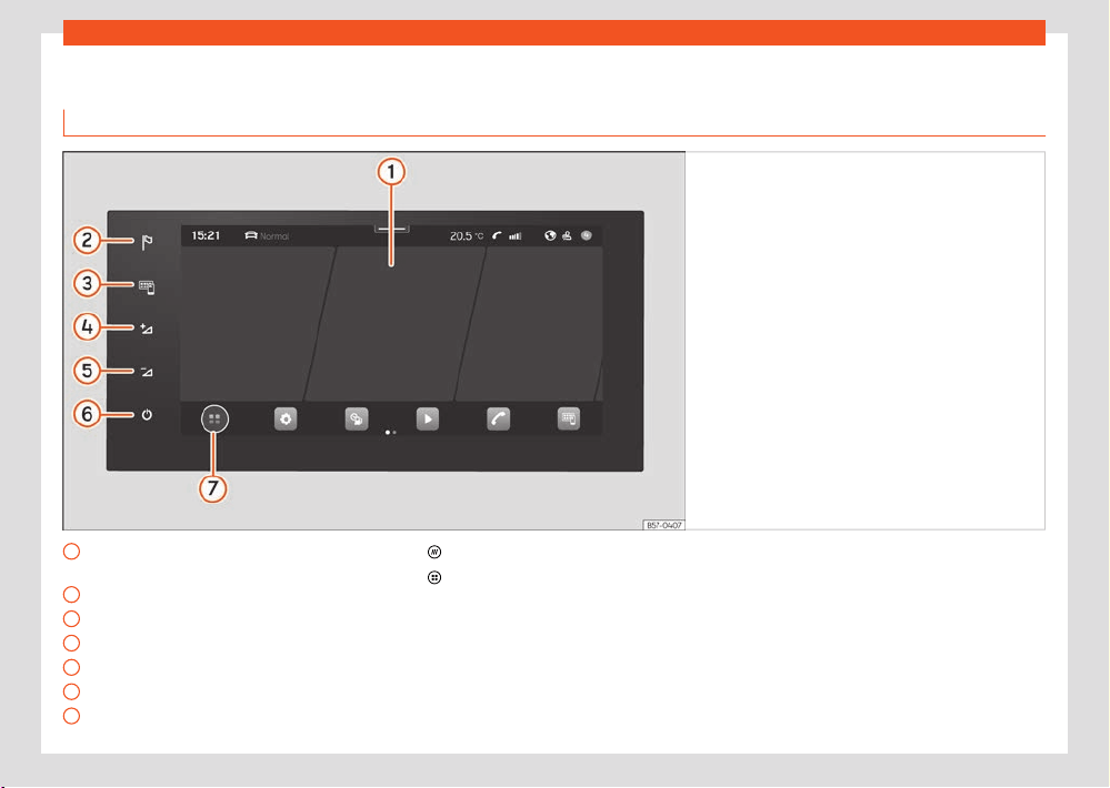
Infotainment system
257
Overview and controls
Overview and controls
Connect Syst
em
Fig.186 Ov
erview: control unit
1
Touch screen. The infotainment functions
can be used through the screen.
2
Navigation Menu
3
Full Link menu
4
Turn volume up
5
Turn volume down
6
Turn the infotainment on/o
7
HOME button.
: main menu with widget views.
: main menu in tile mode.
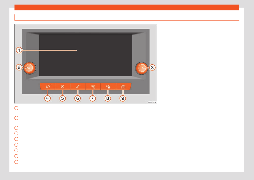
258
Infotainment system
Media System
Fig.187 Ov
erview: control unit and indication in
the 8.25-inch version
1
Touch screen. The infotainment functions
can be used thr
ough the screen.
2
Rotary push button (to adjust the volume
and t
o switch the infotainment on/o)
3
Rotary push button (to search and select)
4
HOME button (to open the start page)
5
Radio/Multimedia ›››page266
6
Telephone ›››page280
7
Full Link ›››page2
48
8
Vehicle information ›››page36
9
Vehicle settings ›››page37
Infotainment system
259
General instructions for use
General instructions for use
Oper
ating indications
●
The infotainment needs a few seconds for
the compl
ete start-up of the system and during
that time it does not react to inputs. Only the
image of the rear view camera system can be
displayed during system start-up.
●
The display of all indications and the execu-
tion of functions only takes place once the info-
tainment system has finished booting. The du-
ration of the system booting depends on the
number of infotainment functions and may take
longer than normal in the event of very high or
very low temperatures.
●
When using the infotainment system and
corresponding accessories, e.g., headphones,
bear in mind country-specific regulations and
legal provisions.
●
Some functions of the infotainment system
require an active SEAT CONNECT user account
and an Internet connection for the vehicle. The
data transmission must not be limited to per-
form the functions.
●
To use the infotainment system, simply lightly
press a button or touch the screen.
●
For the correct operation of the infotainment
system it is important that it is switched on and
that, if necessary, the time and date of the vehi-
cle are set correctly.
●
If a function button is missing on the screen,
it is not a de
vice defect, but corresponds to the
specific equipment of the country or version.
●
Some infotainment functions can only be se-
lected when the vehicle is at a standstill. In
some countries, the selector lever must also be
in the parking position P or in neutral position N.
It is not a malfunction, but is due to compliance
with legal provisions.
●
Restrictions on the use of devices using Blue-
tooth® technology may apply in some coun-
tries. For further information, contact the local
authorities.
●
If you disconnect the 12 volt battery, turn on
the ignition before restarting the infotainment
system.
●
If the setup is changed, this may change the
display on the screen and in some cases, the
infotainment system may behave in a manner
dierent to that described in this instruction
manual.
●
In some countries, the infotainment system
automatically shuts o when the engine is
switched o and the vehicle's 12-volt battery
charge level is low.
●
Ensure that any repairs or modifications that
need to be carried out on the infotainment sys-
tem are carried out by a specialised workshop.
SEAT recommends visiting a SEAT dealership
for this.
●
Using a mobile phone device inside the vehi-
cle may cause noise in the speakers.
●
On vehicles with park assist, the audio source
volume is automatically lowered when reverse
gear is selected, as well as when the doors are
opened. The volume reduction can be adjusted.
●
Information about the included software and
the license conditions can be found in Set-
tings > Copyright.
●
When selling or lending the vehicle, make
sure that all saved data, files and settings have
been deleted and, if necessary, external audio
sources and data media have been removed.
Note
You will find mor
e information and tips for
using the infotainment system in the Help
menu.
HOME screen
In the control and display unit you can set
up the views and representation on the home
screen or use the factory setting templates.
If an icon is missing on the screen, it is not a
device defect, but corresponds to the specific
equipment of the country or version.
The following menus can be included as an
icon on the home screen:
Main menus on the home screen
Navigation ›››page27
3
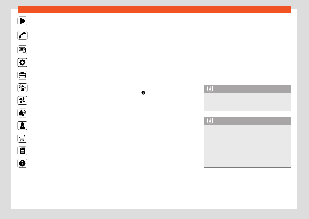
260
Infotainment system
Radio ›››page266, Media ›››page270
Telephone ›››page280
Full Link ›››page2
48
Settings ›››page261
Vehicle ›››page37
Data ›››page36
Air conditioning ›››page131
Sound
Users
Store
Legal
Help
Managing the infotainment system
Execute the functions and settings with the info-
tainment controls.
Depending on the equipment, the infotainment
system has dierent controls:
●
Touch screen.
●
Touch zones outside the screen, for example,
Volume (+ -).
●
Function buttons, for example, RADIO or ME-
DIA.
Opening the Quick Guide
You will find more information and tips for han-
dling in the Quick Guide of the infotainment
system.
●
Press HOME >
.
Connecting and disconnecting the inf
otain-
ment system
The infotainment system turns on when the igni-
tion is switched on, unless it has been manually
turned o beforehand.
The infotainment system starts-up with the last
set volume, provided that this does not exceed
the preset maximum start-up volume.
The infotainment system automatically turns o
when the driver's door is opened, provided the
ignition has been switched o beforehand.
Moving objects and adjusting volume
Move objects on the screen to adapt settings,
for example, with scrollable buttons or to move
the areas of a menu.
Depending on the equipment, menus and dis-
plays can be customised.
Increasing and reducing images or map
sizes
Tip: use your thumb and index finger.
●
Press on the map with both fingers at the
same time and leave them on the screen.
●
To enlarge views, slowly separate one finger
from the other. To reduce views, slowly bring
one finger towards the other.
Note
If you turn on the infotainment system man-
ually with the ignition o, it will aut
omati-
cally turn o after about 30 minutes.
Note
As with most state-of-the-art computer and
el
ectronic equipment, in certain cases the
system may need to be rebooted to make
sure that it operates correctly. To do this, if
appropriate, press and hold the On/O but-
ton of the infotainment system () for approx.
15 seconds until the SEAT logo appears on
the display.
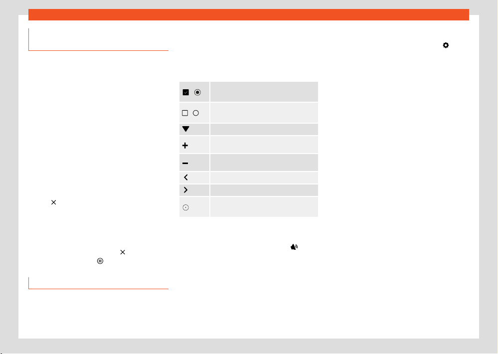
Infotainment system
261
General instructions for use
Customising the infotainment sys-
t
em
Customise the menus and infotainment views
to quickly access your favourite or most fre-
quently used functions.
The main menu contains function buttons for
accessing all of the Infotainment apps.
Customise shortcuts
At the bottom of the screen you will find short-
cuts to customisable system functions. Use the
settings to delete or replace them, or change
their order.
●
Press and hold one of the icons (or press +
of an empty position) to display an additional
window.
●
Select one of the icons from the apps bar.
●
Press
to delete an icon.
●
Click on an icon in the additional window to
r
eplace the value.
●
Hold your finger on one of the icons and drag
it to the desired position.
●
To close the edit mode, press
in the addi-
tional windo
w, or press
.
Settings (syst
em and sound)
The selection of possible settings varies de-
pending on the country, the equipment in ques-
tion and the equipment of the vehicle.
Modifying settings
The meaning of the following symbols are valid
for all system and sound settings.
All changes are automatically applied when
the menus are closed.
/
The setting is selected and activated
or connect
ed.
/
The setting is not selected, disabled or
disconnect
ed.
To open a drop-down list.
To increase a setting value.
To reduce a setting value.
To go back step by step.
To go forward step by step.
To change a setting value with the
scr
ollable button without adjusting.
Sound settings
●
Access the sound settings: HOME >
.
In the sound settings ther
e may be the following
functions, information and setting options:
●
Equaliser.
●
Position.
●
Settings.
System settings
●
Access the system settings: HOME >
.
In the syst
em settings there may be the follow-
ing functions, information and setting options:
●
Screen.
●
Time and date.
●
Language.
●
Additional keypad languages.
●
Units.
●
Voice control.
●
Wi-Fi.
●
Data connection.
●
Manage mobile devices.
●
Reset factory settings.
●
System information.
●
Copyright.
●
Configuration wizard.
Adjust the volume of external audio sources
If you need to increase the playback volume for
the external audio source, first lower the volume
on the infotainment system.
If the sound from the connected audio source
is very low, increase the output volume on
the external audio source. If this is not enough,
change the input volume to medium or high.
262
Infotainment system
1)
Equipment name: Media System.
If the sound from the connected external audio
sour
ce is too loud or distorted, lower the out-
put volume on the external audio source. If this
is not enough, change the input volume to me-
dium or low.
Clean the screen
Remove persistent dirt carefully and without us-
ing aggressive cleaning products. To clean the
screen we recommend that:
●
The infotainment system is switched o.
●
Use a clean, soft cloth dampened with water
›››page367.
●
In case of persistent dirt: soften the dirt by
moistening with a little water. Then carefully re-
move with a clean, soft cloth.
NOTICE
Cleaning the screen with inappropriate
cl
eaning products or when dry, may damage
it.
●
When cleaning, only press lightly.
●
Do not use aggressive cleaning products
or that contain solvents. Such products
may damage the equipment and darken the
screen.
Trademarks, licenses and copyrights
R
egistered trademarks and licenses
Certain terms in this manual bear the symbol
® or ™. These symbols indicate that they are
trademarks or registered trademarks. The ab-
sence of this symbol, however, does not neces-
sarily mean that the term in question can be
used freely.
Other product names are registered trade-
marks of the respective rights holders.
●
Manufactured under license from Dolby Lab-
oratories. Dolby and the double-D symbol are
trademarks of Dolby Laboratories.
●
Manufactured under license from Dolby Lab-
oratories. Dolby, Pro Logic and the double-D
symbol are trademarks of Dolby Laboratories.
●
Android Auto™ is a trademark of Google Inc.
●
Apple CarPlay™ is a trademark of Apple Inc.
●
Bluetooth® is a registered trademark of Blue-
tooth® SIG, Inc.
●
iPod®, iPad® and iPhone® are trademarks of
Apple Inc.
●
MirrorLink® and MirrorLink® Logo are certified
trademarks of Car Connectivity Consortium
LLC.
●
Windows® is a registered trademark of Micro-
soft Corpor
ation, Redmond, USA.
●
MPEG-4 HE-AAC audio coding technology
and pat
ents are licensed by Fraunhofer IIS.
●
This product is protected by certain Microsoft
Corporation industrial and intellectual property
rights. The use or commercialization of technol-
ogy of this type outside the configuration of this
product, without a licence from Microsoft or an
authorised Microsoft branch is prohibited.
Copyright
As a general rule, audio and video files stored
on data media and audio sources are subject to
intellectual property protection in accordance
with the national and international provisions
applicable in each case. Please bear in mind all
legal provisions!
Technical data
Radio with integrated hardware (8.25 ")
1)
The factory-mounted radio in the vehicle with
integrated hardware includes country-specific
components and software for connectivity and
for the execution of vehicle, comfort and info-
tainment functions.
The corresponding indications are displayed on
the radio screen and partly on the instrument
panel.
●
Capacitive colour screen:

Infotainment system
263
General instructions for use
1)
Equipment name: Connect System
–
8.25 inch version, TFT, WVGA: 1082 x 480
pix
els.
●
Touch operation via the device screen, rotary
push-button, menu button and buttons on the
multifunction steering wheel.
Central computer with control and display
unit
1)
The factory-mounted central computer in the
vehicle includes country-specific components
and software for connectivity and for the ex-
ecution of vehicle, comfort and infotainment
functions.
The corresponding indications are shown on
the control and display unit screen and partly
on the instrument panel.
●
Capacitive colour screen
●
Using the equipment with:
–
Touch zones Touch operation.
–
Buttons on the multifunction steering wheel.
–
Approach sensors (driver and passenger
side r
ecognition, gesture control).
Vehicle and comfort functions
●
Assistants system settings.
●
Heating and air conditioning settings.
●
Lights and visibility function settings.
●
Vehicle comfort settings.
●
Parking and manoeuvring settings.
Sound syst
em (basic equipment):
The infotainment system that is supplied from
the factory is equipped as follows:
●
Speakers in dierent locations and with dif-
ferent power levels (watts).
●
Internal amplifier depending on the system:
–
8 speakers: 4 x 20 W
Setting options:
●
Equaliser, depending on the system:
–
8 speakers: 5 frequency bands and default
settings.
●
Sound distribution, depending on the system:
–
8 speakers: Balance + Fader (left / right /
front / rear).
●
Sound optimisation by zones (valid for the 8-
speaker system):
–
Manual (Driver and All)
–
Automatic depending on the seats occu-
pied.
Optional sound system
The infotainment system can be extended with
an optional sound system as follows:
●
10 speakers in dierent locations and with dif-
ferent power levels (watts).
●
External amplifier (400 W Ethernet), which
processes the audio signals sent by the central
computer.
●
Excitation of speaker channels through class
AB final stages.
●
Audio signal processing in digital internal sig-
nal processor (DSP).
●
Independent subwoofer in the luggage com-
partment.
Setting options:
●
User equaliser: 5 bands.
●
Sound distribution: Balance (left / right) +
Fader (front / rear).
●
Sound optimisation by zones:
–
Manual (Driver, Front and All)
●
Subwoofer volume.
●
Surround settings.
Wi-Fi
●
Wi-Fi conforming to IEEE 802.11 b/g/n.
●
2.4 GHz and 5 GHz transfer (depending on
the country).
●
Apple Car Play™ and Android Auto™ over Wi-
Fi
●
Simultaneous connection of up to 8 Wi-Fi de-
vices.
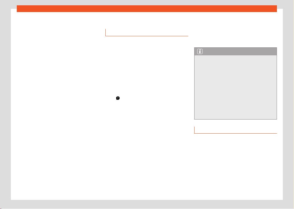
264
Infotainment system
●
Media System:
–
5GHz access point for Full Link Wireless
only
●
Connect System:
–
Access point
–
Tethering
–
Pairing process simplified by WPS or QR
code
Bluet
ooth® profiles
There can be a maximum of two mobile devices
connected to the Bluetooth® hands-free and a
third device connected to the Bluetooth® as a
music player.
When a mobile phone is connected to the tele-
phone management system, a data exchange
takes place via one of the Bluetooth® profiles.
●
Hands-free telephone profile (HFP): the
HFP can be used to manage calls through the
infotainment system.
●
Audio profile (A2DP): This profile allows au-
dio to be transmitted with stereo quality. It may
require connecting other profiles for managing
and controlling playback.
●
Phone book access profile (PBAP): Allows
phone book contents to be downloaded from
the mobile telephone.
●
Messaging profile (MAP): It allows short
messages (SMS) and emails to be downloaded
and synchronised.
Voice control
Introduction
Voice control works both online and oine, tak-
ing into account the aspects indicated in the
section “Languages available depending on
the market”. In online mode, commands are re-
corded more accurately, as more data is avail-
able.
Voice control understands questions and ex-
pressions without having to learn commands.
Commands can be formulated freely and can
be colloquial. Command proposals can be
found in the infotainment system, for example
in the
Help > Voice control menu.
Functions are reduced in oine mode.
Loud noises inside or outside the vehicle can
cause malfunctions, as well as confusing phra-
ses and answers.
Languages available depending on the mar-
ket
●
Online and oine: German, American Eng-
lish, British English, French, Italian, Spanish,
Czech, Dutch, Polish, Portuguese, Swedish,
Danish and Norwegian. These languages have
advanced functions such as Online Com-
mands, natural interaction, etc.
The other languages of the infotainment system
do not oer natural interaction.
Requirements
●
Online and oine: v
oice control with the cor-
responding infotainment installed in the vehicle.
●
Online: current SEAT CONNECT Plus contract
active.
Note
●
Voice control only recognises commands
in the l
anguage that is set in the infotainment
system.
●
Test the voice control with the vehicle stop-
ped before starting to move to familiarise
yourself with its operation.
●
Online voice search will be faster and more
reliable if the “Use location” privacy setting
is selected.
●
Voice control can only control functions
that are available as part of the vehicle’s
equipment.
Wake word and commands
Voice control wake words
Voice control starts when the infotainment rec-
ognises the wake word.
If you have connected the voice control using
the wake word, the connected infotainment an-
swer with “How can I help you? ”.
●
OR: aft
er the wake word, say the desired
command, for example: “Hola Hola” and then
“heating”.
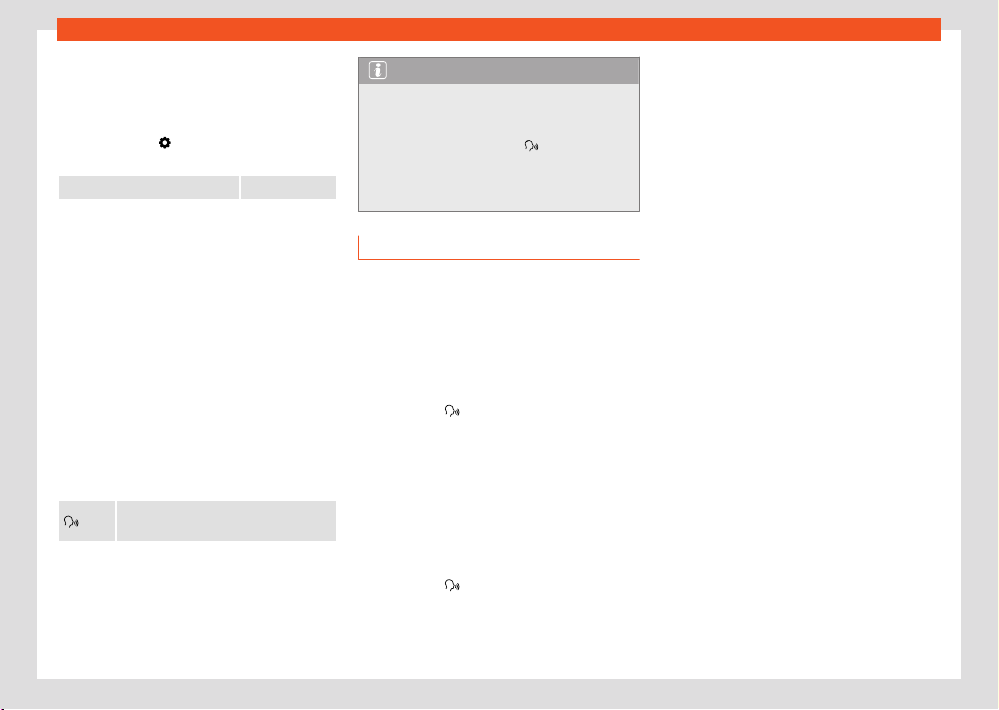
Infotainment system
265
Voice control
The system scans the words spoken in the vehi-
cl
e after the wake word.
Connect and disconnect the wake word
●
Press HOME >
Settings > Voice control >
Activ
ate / deactivate wake word.
Wake word: Hola Hola
Commands
To help the voice control recognise commands
reliably:
●
Pronounce clearly. Confusing commands are
not recognised. Speak in a normal tone of
voice. Speak a little louder if you are driving at
high speed.
●
Avoid outside noises. Open windows and
doors can interfere with voice control.
●
Avoid other secondary noises, such as con-
versations in the vehicle. Do not direct the air
flow from the outlets towards the microphone
or the interior lining of the roof.
●
Do not make long pauses.
Voice control is active and recognises
the w
ords pronounced.
Note
●
When the activation word is disconnected,
the inf
otainment system cannot be activated
by means of the activation word. Voice con-
trol is still available via the
button on the
multifunction st
eering wheel.
●
Availability depends on country and equip-
ment.
Start and stop voice control
Depending on the equipment, you can start
voice control in dierent ways.
Start voice control
●
Voice control activation: say the word that
activates voice control.
●
Multifunction steering wheel: press the voice
control button
.
In some cases you can al
so start voice con-
trol of the connected mobile phone device, by
pressing and holding the voice control button.
Manually ending voice control
Voice control can be cancelled with the Can-
cel command.
●
Multifunction st
eering wheel: press the voice
control button
twice in a row, or press and
hol
d.
The voice control ends automatically, if you use
inf
otainment functions, if the parking system is
activated or by incoming calls.
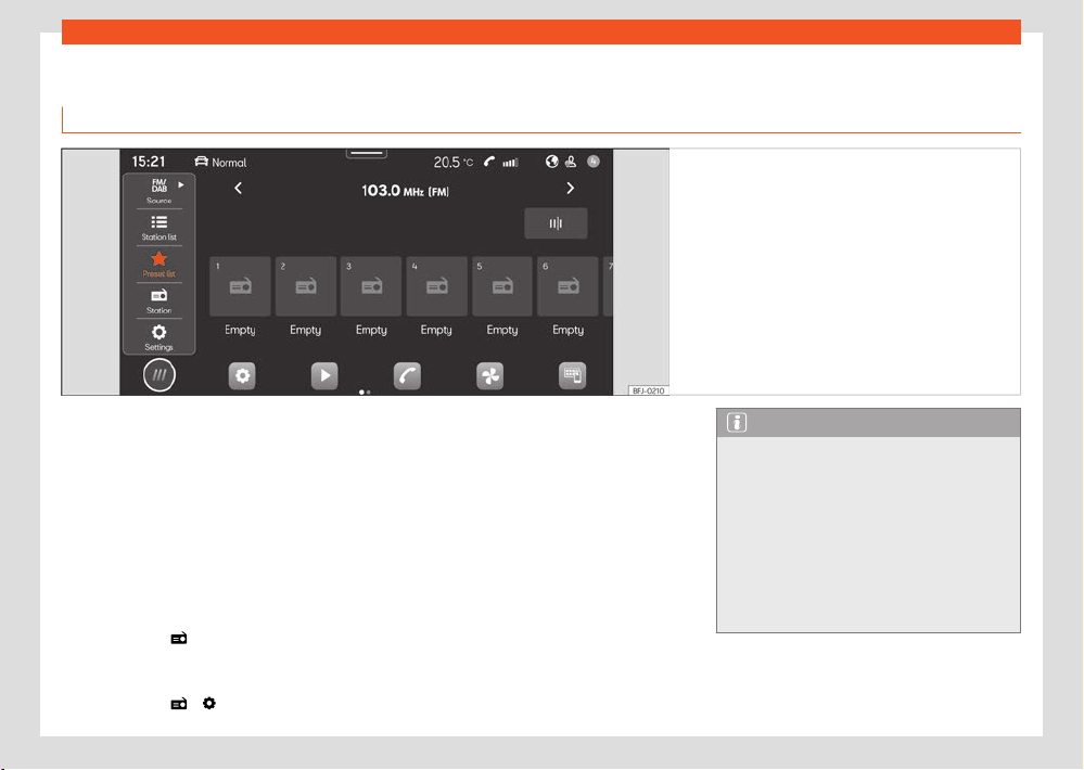
266
Infotainment system
Radio mode
Intr
oduction
Fig.188 Schematic diagr
am: Radio view.
In Radio mode you can tune in the available
r
adio stations in dierent frequency bands and
memorise your favourites on the preset buttons
to access them quickly.
The types of reception and frequency bands
available depend on the equipment and the
country. In certain countries, frequency bands
may stop broadcasting or not be available
again.
Access the RADIO menu
●
Press HOME > ›››Fig.188.
Access the settings
●
Press HOME > > .
Online functions in Radio mode
Online functions in Radio mode are only availa-
ble under the following conditions:
●
SEAT CONNECT or SEAT CONNECT Plus
equipment.
●
You have an active SEAT CONNECT user ac-
count.
●
The vehicle is assigned to your user account.
●
You have a corresponding data package ac-
quired from the In-Car store or have a data
volume for your own mobile phone device via
Wi-Fi access point.
Note
●
For streaming services you need to have an
account with the provider in question.
●
Radio stations are responsible for the con-
tent of the information they transmit. Elec-
trical equipment connected to the vehicle
may also cause interference in radio signal
reception and noise in the loudspeakers.
●
Foil or metal-coated stickers attached to
the windows may aect reception on vehi-
cles with a window aerial.
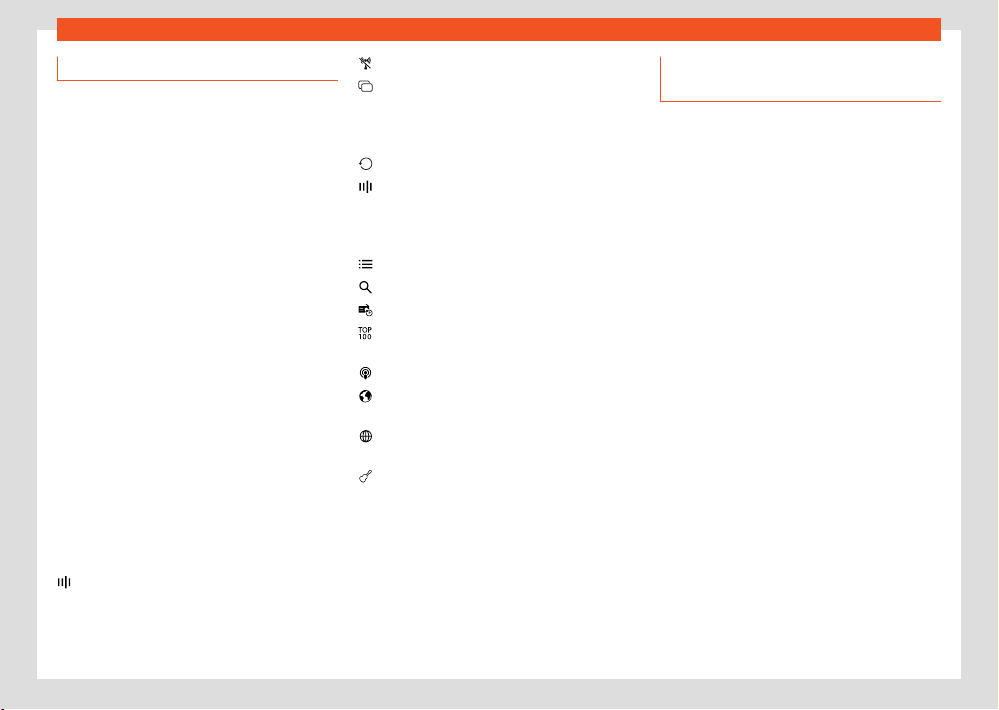
Infotainment system
267
Radio mode
AM
FM/DAB
Internet radio
TP
Radio equipment and symbols
The functions, as w
ell as the types of reception
and frequency bands available depend on the
equipment and the country.
●
AM tuner.
●
Dual FM receiver (diversity antenna).
●
Summarised FM station list.
●
Merger of DAB and FM stations into one list.
●
Fusion of all stations stored in preset buttons
into one list. Maximum 36 favourite stations.
●
Station logos.
●
DAB presentation (slideshow). Images that
are emitted sequentially.
●
Internet radio.
Universal symbols in Radio mode
To select the desired AM frequency band.
T
o select the desired FM/DAB fre-
quency band.
To select the type of Internet ra-
dio reception.
Next to the name of the station, monitoring
of active trac information stations (TP).
Symbols on the FM/DAB frequency band
To display the frequency band for manual
selection of the FM frequency. Only possi-
ble when the summary station list is discon-
nected.
DAB not available.
D
AB stations support presentations (slide-
show).
Symbols on the AM frequency band
Manually updating the station list.
To display the frequency band for manual
selection of the AM frequency.
Menus in Internet radio mode
Show station selection.
Open text search.
Show the last online radio stations heard.
Show the 100 most played radio stations
and podcasts.
Show available online radio podcasts.
Show online radio stations, grouped by
country.
Show online radio stations by the desired
language.
Show online radio stations whose pro-
gramme belongs to the desired musical
genre.
Selecting, tuning and saving a sta-
tion
Select the frequency band
Before selecting a station you have to select
a frequency band or a type of reception. Dier-
ent stations are available depending on the fre-
quency band selected or the type of reception.
The types of reception and frequency bands
available depend on the equipment and the
country.
●
Select the frequency band or type of recep-
tion: AM, FM/DAB, FM (for devices that do not
have DAB), Internet radio.
Search and select a station
You can select radio stations in dierent ways.
The options vary depending on the frequency
band and the type of reception.
Select via the frequency band (AM and FM)
1. Activate the frequency band.
2. Click on the cursor, scroll through the fre-
quency band and release it when you
reach the frequency band you want.
OR: press on a point on the frequency
band. The cursor will automatically jump to
the corresponding frequency.
The station of the set frequency is tuned.

268
Infotainment system
Select from the station list (AM and FM/DAB)
The st
ation list shows the stations that are cur-
rently tunable. In the AM frequency band, you
may have to update the station list if you are no
longer in the area where you last accessed the
station list. In the FM/DAB frequency band, the
station list is automatically updated.
1. Open the station list
2. Press the station you want.
The selected station is tuned. In the case of
FM/DAB and if the station is available, the best
quality reception is automatically selected.
Search and filter stations (Internet radio)
In Online Radio mode, stations can be filtered
by categories and can be searched by text.
1. Open the station list.
2. Select the category by which the stations
are to be filtered.
OR: press
to start the text search. The
input fiel
d is displayed.
3. Enter the name of the station you want. The
list of the stations found is updated while
entering the text.
4. Press the station you want.
The selected station is tuned.
Search in SCAN mode (AM and FM/DAB)
In SCAN mode the stations are automatically
tuned in a sequential manner and each of them
is played for approx. 5 seconds.
●
To start the SCAN mode, under Settings
press SCAN.
SCAN mode starts and the station currently
tuned in is shown on the screen. Next to it is a
SCAN function button.
●
To select a station press SCAN.
SCAN mode stops and the station is tuned. The
SCAN function button is hidden.
Storing the station on the preset buttons
You can store up to 36 stations of dierent fre-
quency bands and reception types as favour-
ites using the preset buttons.
1. Tune the station you want.
2. Access the preset buttons.
3. Press the preset button and keep it pressed
until the station is stored.
OR: press the station on the station list and
keep it pressed. The preset buttons are dis-
played.
4. Press the preset button.
The station is stored in the selected preset but-
ton.
If a station was already stored in the preset
button, it is overwritten with the new station.
Special functions in Radio mode
Trac information (TP)
The TP function monitors the announcements
of a station with trac information and auto-
matically reproduces them in the Radio mode
or in the multimedia playback that is active. To
do this, you have to be able to tune into a sta-
tion with trac information.
Some stations without their own trac informa-
tion support the TP function by broadcasting
trac information from other stations (EON).
In the AM frequency band or in the Multimedia
mode, a station with trac information in the
background is automatically tuned while it is
possible to tune into a station with trac infor-
mation.
If no station with trac information can be
tuned in, the device automatically searches for
stations with tunable trac information.
Stations with trac information are not availa-
ble in all countries.
Activating and deactivating the TP function
●
In Radio mode or Multimedia mode, press
> T
rac programme (TP).
Presentations (SlideShow) in DAB
The slideshow function (SLS) is a feature of digi-
tal radio (DAB) stations, allowing a slideshow of
images, e.g. the station’s logo, to the user.

Infotainment system
269
Radio mode
Activating and deactivating the SLS function
It is possibl
e to deactivate the slideshow func-
tion on DAB radio stations:
●
In the Radio Menu click on the area where
the station information is located, either in the
name or on the additional information (author
or information text).
●
OR: in the menu
> Slide Show (s
witch on/
o).
Online radio
Online radio is a type of reception for Internet
radio stations and podcasts that are independ-
ent of AM, FM and DAB. Thanks to Internet
transmission, reception is not limited to the re-
gion.
Online radio is only available through the Inter-
net connection of the active infotainment sys-
tem. The use of online radio can generate ex-
penses due to the transmission of data from the
Internet.
●
In Online radio mode, press and set the audio
quality to high or low to tune the online radio.
Station logos
In the case of some frequency bands, station
logos may already be pre-installed in the info-
tainment system.
If in the FM/DAB frequency band settings the
automatic selection of station logos is acti-
vated, station logos are automatically assigned
to the stations.
In the Online radio mode, the infotainment sys-
tem accesses the station logos of the online
database and automatically assigns them to
the stations.
Assign station logos manually
1. In FM/DAB mode, press Station logos.
2. Press on the
icon and then select the
st
ation to which a station logo is to be as-
signed.
3. Select the station logo. If desired, repeat
the same process with other stations.
4. OR: via the menu
> Station logos.
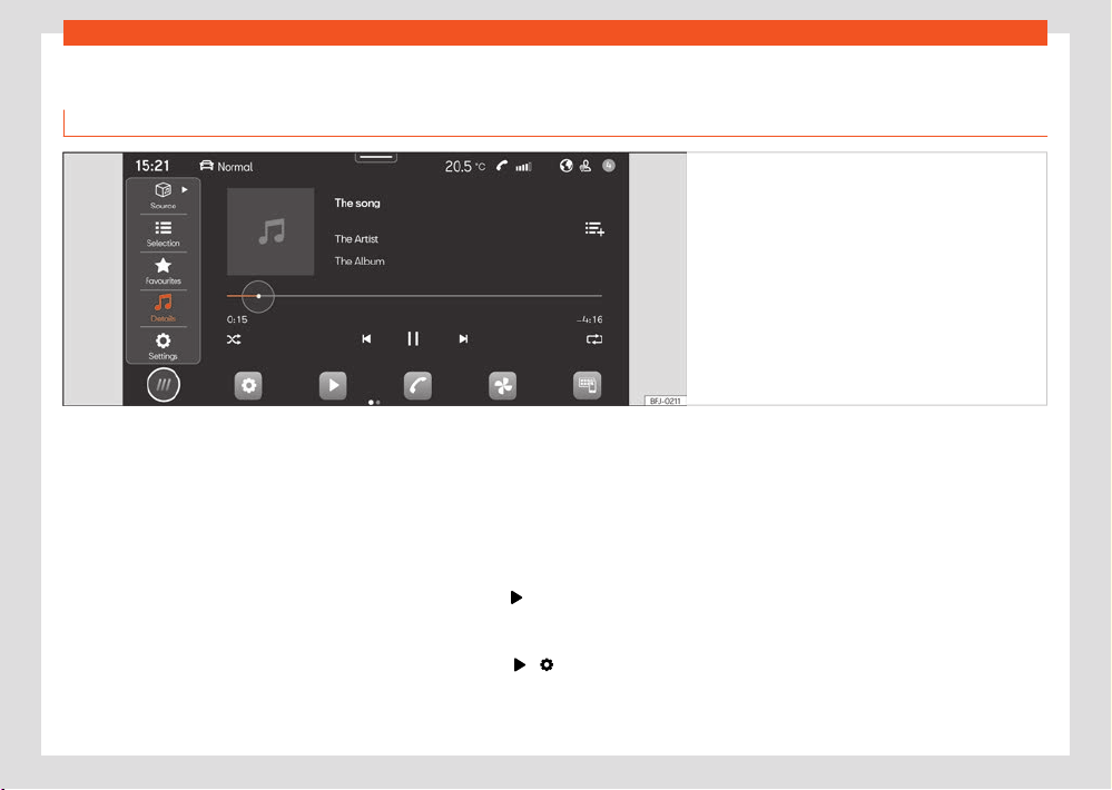
270
Infotainment system
Media Mode
Intr
oduction
Fig.189 Schematic diagr
am: Media view
In Media mode you can play multimedia
fil
es from data media and streaming services
through the infotainment system.
Depending on the equipment, the following
data media can be used:
●
USB storage support (for example, a USB
stick, a mobile phone connected via USB).
●
Bluetooth® device (for example, a mobile
phone or a tablet).
Depending on the equipment, the following
types of multimedia files can be played:
●
Audio files.
●
Video files (depends on the system).
You can also use streaming services. The avail-
ability of streaming services depends on the
equipment and the country.
To use streaming services you need to have
your own user account in the streaming service
in question.
Access the MEDIA menu
●
Press HOME > ›››Fig.189.
Access the settings
●
Press HOME > > .
Limitations and indications of data media
Data media may not work if they have been ex-
posed to high temperatures or have been dam-
aged. Please bear in mind the manufacturer’s
indications.
Quality dierences between data media pro-
duced by dierent manufacturers can cause
multimedia playback malfunctions.
Incorrect configuration on a data media may
cause the data media to be unreadable.
Playlists only specify a playback order and re-
fer to the storage location of the multimedia
files within the folder structure. In a playlist
there are no multimedia files saved. To play a
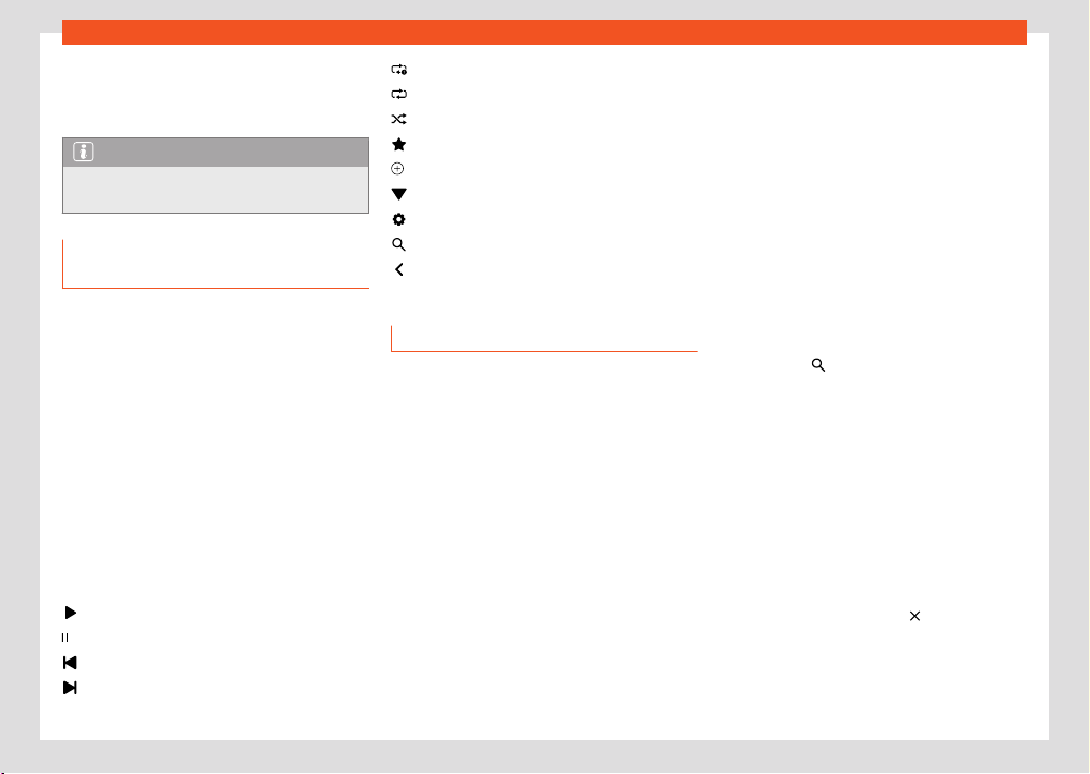
Infotainment system
271
Media Mode
playlist, multimedia fil
es have to be found in the
storage places of the data media to which the
playlist refers.
Note
SEAT assumes no liability for any deteriora-
tion or l
oss of files on data storage devices.
Equipment features and media sym-
bols
Audio, multimedia and connectivity:
●
Media playback and control via Bluetooth®.
●
Audio playback in these formats: AAC, ALAC,
AVI, FLAC, MP3, MP4, WMA.
●
Video playback in these formats: MPEG-1
and MPEG-2 (.mpg, .mpeg), ISO MPEG4, DivX
3, 4 and 5 Xvid (.avi), ISO MPEG4 H.
264
(.mp4, .m4v, .mov), Windows Media Video 10
(.wmv, .asf).
●
Playlists on any type of device.
●
Multimedia streaming (online).
●
Multimedia search.
Universal symbols in Media mode
Start playback.
Pause playback.
Change to the previous track.
Change to the next track.
Repeat the track that is playing.
R
epeat all titles.
Activate the shue playback order.
Display a list of favourites.
Add a media file as favourite.
Top right: select media source.
Access the settings.
Open the search.
Return to the top folder of the media
source.
Select and play a multimedia source
Select multimedia source
Before playing multimedia files you must first
connect a multimedia source.
To use streaming services you must be connec-
ted to the Internet.
●
Connect an external multimedia source.
●
Select the connected media source to be
used for playback.
Playing audio and video files
You can search and play multimedia files from
an available multimedia source in dierent
ways.
Search in the folder structure
Multimedia files can be catalogued by catego-
ries (for example, album, artist, title). In My me-
dia this category view is always displayed. The
classic folder structure of individual USB data
media is also found in My media.
1. Activate the folder structure.
The folder structure of the selected multi-
media source is displayed. When My media
is selected, the categories (music, videos,
playlists) and connected multimedia sour-
ces are displayed first.
2. Search for the title you want in the folder
structure.
OR: press
to start a text search The input
fiel
d is displayed.
3. Enter the name of the desired title. The list
of the titles found is updated while entering
the text.
4. Press the desired title.
If at the beginning of the playback your se-
lection is in a folder of a multimedia source,
the multimedia files that are in it are also
added to the playback.
If a playlist is played, all available titles in
the playlist are added to the playback.
5. Close your selection with
.
Sel
ect favourites
In favourites you can save titles, music genres,
artists and albums individually for playback.

272
Infotainment system
●
Access favourites
.
●
Press the favourite you want.
Depending on your sel
ection, all the titles be-
longing to the favourite are added to the play-
back.
Save favourites
Only multimedia files in My media of the info-
tainment system can be saved as favourites.
You can save up to a maximum of 30 titles, al-
bums, artists and music genres individually as
favourites.
1. Start playback.
2. Access favourites.
3. Tap a favourite that is not assigned.
OR: press and hold on an existing favourite
for approx. 3 seconds.
4. Select from the selection list: Title, Album,
Artist, Genres, Playlist.
The selection is saved instead of the previously
selected favourite. If the favourite was already
assigned, the previously saved favourite is over-
written.
The selectable options in the selection list de-
pend on the data attached to the multimedia
file. If the music genre is not indicated in the
music files, for example, you cannot save the
music genre as favourite.
If a video file is playing, only that video can be
saved as favourite.
Configure streaming services
Depending on the equipment you can use
streaming services directly through the infotain-
ment system. For this you need to have a pre-
mium user account of the streaming service in
question and you have to log in with it in the
infotainment system. You also need to be con-
nected to the Internet.
1. Select
Streaming as the multimedia
sour
ce.
A list of available streaming services is dis-
played.
2. Select the streaming service you want.
3. Follow the steps indicated by the infotain-
ment syst
em.
The streaming service is added to the list
of multimedia sources as a new function
button.
Playing entertainment content in the
infotainment system
Depending on the infotainment system, videos
can be played.
Video mode
When in video mode, a video can be played
on the infotainment screen if this is stored on a
data media, in My media or is sourced from a
streaming service. In this case, the video sound
is played through the vehicle's speakers.
The image is only displayed if the vehicle is
st
opped. When the vehicle is in motion, the in-
fotainment screen turns o. The sound of the
video can still be heard.
A stable Internet connection is required for
playback from a streaming service. In this case,
telephony costs may be generated.
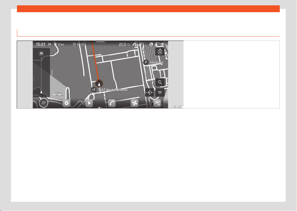
Infotainment system
273
Navigation
Navigation
Intr
oduction
Fig.190 Schematic diagr
am: Navigation view.
A global satellite system determines the current
position of the v
ehicle and the sensors moun-
ted on the vehicle analyse the routes taken.
All measured values and possible trac events
are compared with the available maps to allow
optimal navigation to the destination.
Navigation announcements and graphic repre-
sentations will guide you to your destination.
Navigation management is carried out on the
screen.
Depending on the country, some functions of
the infotainment system will not be available
on the screen when travelling above a certain
speed. It is not a malfunction, but is due to com-
pliance with legislation.
Navigation announcements
Navigation announcements are acoustic indi-
cations for driving referred to the current route.
The type and frequency of navigation an-
nouncements depend on the driving situation,
for example, starting the guide to the destina-
tion, driving on the motorway or on a round-
about and the settings.
If the exact destination cannot be reached be-
cause, for example, it is in a non-digitised area,
indications relating to the address and the dis-
tance to the destination are displayed on the
screen.
During dynamic route guidance, you will re-
ceive information about reported trac con-
gestion on the route. An additional navigation
announcement is given if the route is recalcula-
ted due to trac congestion.
While a navigation announcement is playing,
its volume can be adjusted. The following navi-
gation announcements provided will be played
with the newly adjusted volume.
Limitations during navigation
If the infotainment system cannot receive data
from GPS satellites, for example, in a tunnel or
in an underground garage, navigation contin-
ues using the vehicle's sensors.
274
Infotainment system
In areas that are not digitised or are only parti-
ally digitised on the inf
otainment memory, the
infotainment system will still attempt to provide
route guidance.
In the case of missing or incomplete navigation
data, it may not be possible to determine the
exact position of the vehicle. This may mean
that navigation is not as precise as usual.
Roads and streets are subject to constant
change (e.g. new roads, road works, roads
closed to trac, changes to street names and
building numbers). If the navigation data is ob-
solete, this may lead to errors or inaccuracies
during the route guidance.
Managing the navigation map
To allow an optimal view, you can also man-
age the navigation map with additional finger
movements.
Moving the map
Tip: use your index finger
●
Move the map with your finger.
Zoom in
Tip: use your index finger
●
To increase the view in a certain position,
double-click on the map.
Zoom out
Tip: use your index and middle fingers
●
Press on the map with both fingers at the
same time.
Change view
Tip: use your index finger
●
Press twice on the map and keep your finger
pressed on the screen.
●
To zoom out the view of the map, move your
finger upwards. To zoom in the view of the map,
move your finger downwards.
Change view
Tip: use your thumb and index finger
●
Press on the map with both fingers at the
same time and keep them pressed.
●
To zoom out the view of the map, move one
finger towards the other. To zoom in the view of
the map, move one finger away from the other.
Tilt the view
Tip: use your index and middle fingers
●
Press on the map with both fingers at the
same time and horizontal to each other, keep
them pressed.
●
To tilt the view of the map forward, move your
fingers upwards. To tilt the view of the map
backward, move your fingers downwards.
Rotate the map
Tip: use your thumb and index finger
●
Press on the map with both fingers at the
same time and keep them pressed.
●
To rotate the map view, turn your fingers
clockwise anticlockwise.
Saved data
The infotainment system saves certain data, for
example, frequent routes and position data, to
make the entry of the destination more agile
and optimise the route guidance.
Delete saved data
●
Press Settings > Basic function settings >
Delete and then Accept.
WARNING
Select the settings, enter the destination and
the modifications f
or navigation only with the
vehicle at a standstill.
Note
●
If a detour is passed during route guidance,
navigation may r
ecalculate the route.
●
The quality of the navigation recommen-
dations given by the Infotainment system de-
pends on the navigation data available and
any reported trac congestions.
●
Navigation announcements are not emit-
ted if the sound is muted in the infotainment
system.
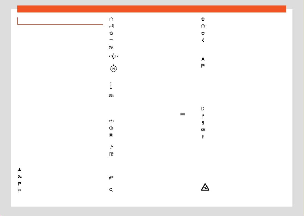
Infotainment system
275
Navigation
Navigation functions and symbols
Navigation
Navigation functions depend on the equipment
and country.
Functions
●
Entering the destination and route calcula-
tion (oine and online).
●
Display of two navigation maps at the same
time (scr
een and instrument cluster).
●
Update of online maps.
●
Predictive navigation.
●
3D urban maps.
●
Online trac information.
●
Dynamic POIs (points of interest).
Symbols on the map
The buttons and indications depend on the set-
tings and the current driving situation.
Symbols for trac events and points of inter-
est (POIs) are displayed on the map, for exam-
ple, petrol stations, train stations or interesting
stopovers, provided navigation has such data
›››page278.
Current position.
Sear
ch for destinations.
Destinations along the route.
Final destination.
Home address.
W
ork address.
Favourite destinations.
Additional window with more options.
Additional window with route options.
Centre the map on the current position.
Change view: 2D oriented to the north, or
2D oriented to the direction of travel, or
3D to the direction of travel.
Information about the current route guid-
ance.
Map scale.
Symbols in the additional window
●
To open the additional window, press
.
Repeat the last navigation announcement.
V
olume of navigation announcements.
Map lighting in Automatic, Day or Night
mode.
Oer new guidance routes.
360° electric range indicator (hybrid vehi-
cles)
Other symbols
Entering the detailed destination for an ad-
dress.
Search for destinations.
Frequent destinations.
Last destinations.
Favourite destinations.
Back
Symbols in the route details
Current position.
Destination of the current guidance.
POI symbols (points of interest)
POIs (points of interest) are shown on the map,
provided the navigation has said data.
Click on the desired POI (point of interest) to
start a route guidance ›››page276.
Petrol station.
Parking lot.
Tourist information oces.
Train station.
Restaurant.
Trac information.
POIs (points of interest) are shown on the
map, provided the navigation has said data
›››page278.
Click on a trac event to open an additional
window with further details ›››page278.
Slow trac.
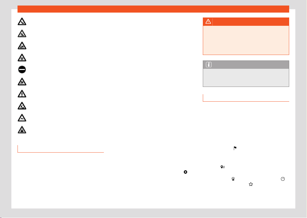
276
Infotainment system
Trac jam.
Accident.
Br
oken down vehicle.
Slippery surface (ice or snow).
Road closed to trac.
Slippery road hazard.
Danger.
Road works.
Strong wind.
Reduced visibility.
Navigation data
The Infotainment system is equipped with a
built-in navigation data memory. Depending
on the country, the necessary navigation data
may already be pre-installed.
To provide correct route guidance and make
the most of the functions oered, the infotain-
ment system should be updated on a regular
basis.
Using obsolete data may lead to errors during
navigation. Current routes cannot be traced or
the route guidances will lead to mistaken desti-
nations.
Ensure navigation data is updated at all times.
Online updating of navigation data
The navigation data of the regions through
which you travel frequently is automatically up-
dated in the background if the Internet connec-
tion is established and the privacy settings are
valid.
●
With the ignition switched on, the navigation
data is updated automatically.
Manual update of navigation data
Current navigation data for large regions, for
example Western Europe, can be downloaded
from www.seat.com and stored on USB data
devices.
●
Download the navigation data to a USB data
device.
●
Turn on the ignition of the vehicle.
●
Connect the USB data device to the infotain-
ment system. Navigation data is automatically
updated in the background.
The map version is displayed in HOME >
>
Syst
em information.
WARNING
If you update the navigation data manually
whil
e driving, it may cause accidents with se-
rious injuries.
●
Update the navigation data only with the
vehicle at a standstill.
Note
Automatic update of the navigation data is
sub
ject to the privacy settings. No update is
made in incognito mode.
Start route guidance
Depending on the country and equipment, dif-
ferent functions are available to enter destina-
tions.
The dierent functions for entering destinations
are found in the navigation main menu.
Opening the Navigation main menu
●
Press HOME >
.
Sel
ect the destination and start navigation
1. Press
.
2. Select the desired destination. You can
chose fr
om
Frequent destinations,
Last destinations or Favourite desti-
nations.
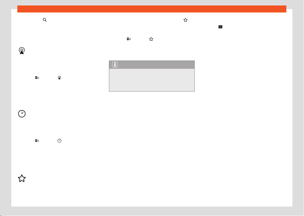
Infotainment system
277
Navigation
OR: pr
ess
and enter the address in the
input scr
een.
OR: detailed address.
3. Press Start.
Frequent destinations
The destination synopsis uses r
ecorded data to
propose possible destinations.
Select the destination and start navigation:
1. Press
and then .
2. Select the desired destination. The route
guidance st
arts automatically.
Quick start: for a quick start, press and hold
the desired destination for a few seconds.
Recent destinations
Navigation sav
es the last destinations to make
them available for a route guidance.
Select the destination and start navigation:
1. Press
and then .
2. Press the desired destination.
3. Press St
art.
Quick start: for a quick start, press and hold
the desired destination for a few seconds.
Favourite destinations
Sav
e up to 20 destinations as favourites.
To save a destination as a favourite press
in
the split scr
een when entering the destination.
Select the destination and start navigation:
1. Press
and then .
2. Press the desired destination.
3. Press St
art.
Note
Enter the destination as accurately as possi-
bl
e. If you enter a destination incorrectly, the
route guidance will not be able to start or it
will guide you to an incorrect destination.
Start route guidance by selecting from the
map
The navigation map includes active areas at
many points that are suitable for entering the
destination. To do this, press the desired posi-
tion or place on the map. If there is map data at
this point, you can start a route guidance.
Whether it is possible to enter the destination
through the navigation map depends on the
state of the data and it is not possible for all
positions.
To start “oroad navigation”, press an empty
area without position data.
Start navigation:
1. Press
.
2. Move the view on the map until the desired
position can be sel
ected. The navigation
map can be used by means of additional
finger movements ›››page273.
3. Press the desired destination on the map.
4. Press Route.
Oroad navigation
“Oroad navigation” calculates routes to se-
lected destination points using unknown data.
When a destination point is outside the known
roads or position data, navigation finds the
route to the next point of the known road and
completes the path to the next destination
point with a direct connection.
Start navigation:
1. Move the view on the map until the desired
position can be selected. The navigation
map can be used by means of additional
finger movements ›››page273.
2. Press on any point on the map without posi-
tion data.
3. Press Route.
Start route guidance using contact details
Start route guidance with the saved address
data of a contact. Contacts saved without ad-
dress data cannot be used for route guidance.
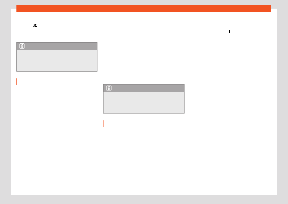
278
Infotainment system
Start navigation:
1. Press .
2. Press on the contact you want.
3. Press R
oute.
Note
If the address details of a contact are ob-
sol
ete, the route guidance will nevertheless
take you to the registered address. Check
that the contact address is updated.
Trac information
The infotainment system receives detailed traf-
fic information automatically if the Internet con-
nection is established. This information is shown
with symbols and highlighting the road network
in colour on the map.
Trac incidents
Trac incidents, for example, trac jams or
congested trac, are shown on the navigation
map using symbols.
With an active route guidance, trac incidents
that are on the current route are shown in the
route details. Such trac incidents can be avoi-
ded ›››page278, Function descriptions.
Hazard information
Hazard information is shown on the navigation
map with symbols in the same way as trac
incidents. In this case, the source of this infor-
mation is another vehicle that has detected the
hazard and has uploaded the information to the
service provider.
The hazards shown are: accident, broken down
vehicle and slippery road surface.
Trac flow indication
The navigation map shows trac flow accord-
ing to current trac events, highlighting the
road network in colour.
●
Yellow: Slow trac.
●
Red: Trac jam.
Note
Trac inf
ormation receipt is subject to the
privacy settings. In maximum Privacy mode,
no trac information is received. Tracking or
Location level setting is necessary.
Function descriptions
Route details
The route details contain information on all inci-
dents, for example, the starting point, stopovers,
trac events, POIs and destination, provided
the navigation has such data.
If you press on an incident, an additional win-
dow opens providing more options. The avail-
able options depend on the incident and the
current settings.
Open and close the route details
●
To open them, press
or swipe it.
●
To close them, press or swipe it.
Edit r
oute guidance
To edit the route guidance, move the stopovers
to the destination in the TripView view.
●
Hold the desired destination pressed until it is
visibly highlighted.
●
Move the destination to the desired position.
●
Remove your finger from the screen. The
route will recalculate.
Avoid trac incidents
The details of the route show the current traf-
fic incidents if the navigation has such data.
Avoid trac incidents by editing route details
›››page278.
●
Press on a trac event.
●
Press on Avoid. The route will recalculate.
Split screen
When handling navigation functions, an addi-
tional window with other options may open.
Possible options depend on the function being
used.
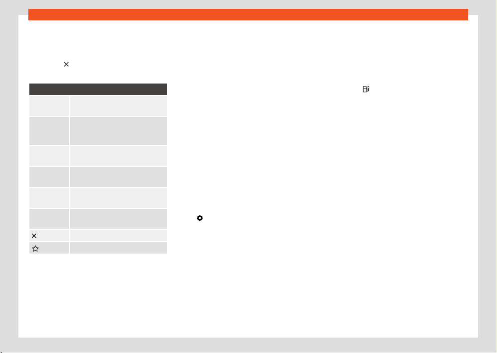
Infotainment system
279
Navigation
Close the additional screen
●
Press on an empty area outside the addi-
tional windo
w.
●
OR: press
.
●
OR: pr
ess Accept.
Functions in the additional window:
Show on
map
Show what is selected on the map.
Add stop-
over desti-
nation
Add a stopover to the route guid-
ance.
Direct
route
Starts direct route guidance.
Delete Delete a stopover from the route
guidance.
Avoid Avoid trac jam. The route will re-
calculate.
Stop route
guidance
Ends the current route guidance.
Close the additional window.
Add a destination to favourites.
Learn usage pattern
When the v
ehicle is in motion, navigation saves
routes and destinations used to automatically
generate destination proposals. Destinations
are learned based on the time of day and the
day of the week.
Navigation can propose up to 5 routes at the
same time. The proposed routes may be dier-
ent from the routes of the normal route guid-
ance.
If one of the proposed destinations is selected,
the guide to that destination is started.
The route guidance follows the selected route
until the vehicle deviates from it. In that case,
the route is recalculated and takes you back
along the most direct path to the initially selec-
ted destination.
Important trac jams are taken into account
in the route guidance, and are avoided if alter-
native routes are available, provided navigation
has such data.
You can activate and deactivate the function
whenever you want.
Enable and disable learning usage pattern
The setting is in the corresponding navigation
menu
> Basic function settings.
●
To activate the function, activate L
earn us-
age pattern.
●
To disable the function, disable Learn usage
pattern.
●
To delete saved data, press Delete usage
pattern.
360° electric operating range display
Valid for: vehicles with plug-in hybrid drive
The 360° electric operating range display
shows the possible range with the current
charge level of the high voltage battery.
Switch on the 360° electric operating range
display
●
Open the additional map window and press
the symbol
.
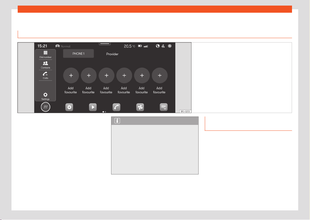
280
Infotainment system
Telephone interface
Intr
oduction
Fig.191 Schematic diagr
am: Phone view.
You can use the telephone interface to connect
your mobil
e to the infotainment system and op-
erate phone functions through it. The sound is
played through the vehicle's speakers.
You can connect up to two mobile phone devi-
ces simultaneously to the infotainment system.
High speeds, poor weather or road conditions
and a noisy ambience (even outside of the ve-
hicle), as well as the quality of reception can all
aect the quality of a telephone conversation
in the vehicle.
Note
●
As a general rule, pairing a device (for ex-
ample, a mobile phone device) is only nec-
essary once. You can restore the device con-
nection via Bluetooth® or Wi-Fi with the info-
tainment system whenever you want without
having to pair the device again.
●
The availability of some telephone func-
tions will depend on the mobile phone con-
nected to the infotainment system.
Telephone interface equipment and
symbols
Equipment features
●
Hands-free function.
●
Use up to two phones at the same time.
●
Phone book with up to 5,000 contacts, de-
pending on the inf
otainment system.
●
SMS functions via Bluetooth®: SMS reading,
SMS writing (templates included), SMS play-
back, message history.
●
Email functions via Bluetooth®: reading email,
writing email.
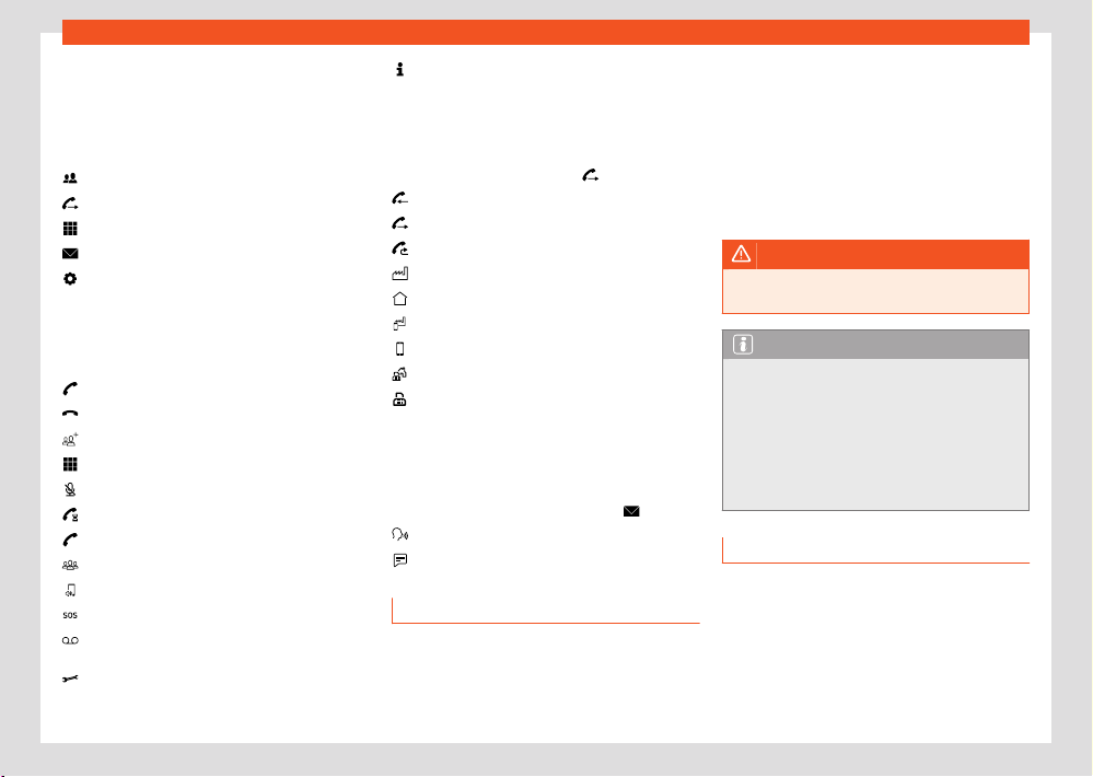
Infotainment system
281
Telephone interface
●
Connection to wireless charging option.
●
Connection to the microphone mounted on
the v
ehicle.
Symbols in the main menu
Contacts.
List of incoming and outgoing calls.
Enter telephone number.
Text messages (SMS and emails).
Telephone interface settings.
Symbols for calls
The symbols may be dierent depending on
the infotainment system.
Start a call or bringing it to the foreground.
End or reject a call.
Open contact list.
Enter telephone number.
Mute the sound of the hands-free
Hold call.
Continue call.
Start conference call.
Pass call to private mode.
Make an emergency call.
Voice mail.
Get help in case of breakdown.
Obtain information on the SEAT brand
and selected additional services related to
trac and your travel.
Call list symbols
●
To open the call lists, press
.
Incoming call.
Out
going call.
Missed call.
Telephone number (company).
Telephone number (private).
Mobile telephone number (company).
Mobile telephone number (private).
Fax (private).
Fax.
Symbols for text messages
The symbols may be dierent depending on
the infotainment system.
●
To open the text messages, press
.
Activate voice control input ›››page264.
T
emplates for text messages.
Places with special regulations
Switch o the mobile telephone and the tel-
ephone interface in places with a risk of ex-
plosion. These places are not always clearly
marked. They include, for example:
●
The vicinity of chemical pipelines and tanks.
●
The lower decks of boats and ferries.
●
In the proximity of vehicles that run on lique-
fied gas (such as pr
opane or butane).
●
Places where the air is laden with chemicals
or particles such as flour, dust or metal powder.
●
All other places where the engine or tele-
phone must be switched o.
WARNING
Switch o the mobil
e phone in areas with a
risk of explosion!
Note
In areas where special regulations apply or
the use of mobil
e phones is forbidden, it
must be switched o at all times. The radi-
ation produced by the mobile phone when
switched on may interfere with sensitive
technical and medical equipment, possibly
resulting in malfunction or damage to the
equipment.
Pair, connect and manage
Requirement for pairing:
●
Bluetooth® is activated on the mobile phone
de
vice.
●
Bluetooth® is activated on the infotainment
system.
282
Infotainment system
Active
Passive
●
Depending on the mobile device, it will be
necessary t
o have the Bluetooth® menu open
or activate the Visibility option so that the de-
vice is visible from the infotainment system.
Pair a mobile phone device suitable for teleph-
ony with the infotainment system to use the
telephone interface functions. On the first con-
nection, the mobile phone device is paired with
the infotainment system. Doing so saves a user
profile ›››page282, User profiles.
The pairing can take a few minutes. The func-
tions available depend on the mobile phone
device used and its operating system.
Pair a mobile phone device
1. Open the list of available Bluetooth® devi-
ces on the mobile phone device and select
the name of the infotainment system.
2. Please note and, if necessary, confirm the
messages that appear on the mobile phone
device and on the infotainment system. If
the pairing was successful, the phone data
is saved in the user profile.
3. Optional: confirm the data transfer mes-
sage on the mobile phone device.
Active and passive connection
To use the functions of the telephone interface,
there must be at least one mobile phone device
connected to the infotainment system. If there
are several mobile phone devices connected
to the infotainment system, you can switch be-
tween active and passive connections. To use
the telephone interface with the desired mobile
phone device, establish the active connection
with the infotainment system.
Dierence between connection types
The mobile phone device is paired and
connected. The functions of the telephone
interface are performed with the data of
said mobile phone device.
The mobile phone device is paired and
connected. Calls can be managed but the
phone book, messages or other functions
will not be active.
Paired mobile phone devices are stored in the
infotainment system, even if they are not cur-
rently connected.
Connect a mobile phone device
Requirement: the mobile phone device is paired
with the infotainment system.
●
Bluetooth® is activated on the mobile phone
device.
Establish an active connection
Requirement: several mobile phone devices are
connected to the infotainment system at the
same time.
●
Select the desired mobile phone device from
the drop-down menu. All other mobile phone
devices are automatically in the passive con-
nection.
User profiles
For each of the paired mobile phone devices an
individual user profile is automatically created.
In the user profile, data from the mobile phone
device is stored, for example, contact details or
settings. A maximum of four user profiles can be
saved in the infotainment system at the same
time.
WARNING
If you perform the pairing while driving, it
coul
d cause an accident or injury.
●
Perform pairing only with the vehicle at a
standstill.
Note
●
While the infotainment system is in the
Kno
wn mobile phones menu, the wireless
charging function is disabled. When you exit
this menu, the wireless charging function is
activated again.
●
In the pairing of some mobile phone devi-
ces, a PIN number is shown on the screen of
the mobile phone device. Enter that number
in the infotainment system to complete the
pairing.
Basic and Comfort Telephony
Depending on the equipment, two types of tel-
ephone interface can be used:
Infotainment system
283
Telephone interface
●
Basic telephone interface.
●
Comfort telephone interface.
Basic t
elephone interface
The Basic telephone interface uses the Blue-
tooth® HFP profile for transmission. This inter-
face allows the use of telephone functions
through the infotainment system and playback
through the vehicle's speakers.
Comfort telephone interface
Like the Basic telephone interface, the Comfort
telephone interface also uses the Bluetooth®
HFP profile.
The Comfort phone interface can be equip-
ped with the wireless charging function
›››page284.
In order to use the functions of the wireless
charging function, you have to place a suitable
mobile phone device correctly in the storage
compartment. The mobile phone device will
then connect to the vehicle antenna. This im-
proves the reception and sound quality of calls.
Calling and sending messages
Open the telephone interface
●
Press HOME >
.
Make a call
Sel
ect a phone number to start a call. Dierent
functions are available for selecting a phone
number:
Contacts
If a cont
act has several registered phone num-
bers you have to select one.
●
Press
and press a number on the list to
st
art the call.
OR: press
and enter the contact name in the
input fiel
d to search for it. Press on the contact
to start the call.
OR: press a favourite in the telephone interface
main menu to start the call.
Calls
The t
elephone interface shows the call list of
the mobile telephone device. Start a call from
the call list.
●
Press
> All and pr
ess a number on the list
to start the call.
OR: press
and filt
er the call list entries (for
example, missed calls or dialled numbers). In
filtered list, press a number to start the call.
Dial number
Manually ent
er a phone number to start a call.
While entering the phone number, contacts that
match that number are shown on the infotain-
ment screen.
●
Press
and enter the telephone number.
Pr
ess
to start the call.
The l
ast call is dialled by pressing and hold-
ing the
button on the multifunction steering
wheel.
Send messages
Depending on the mobil
e phone device and the
infotainment system used, you can send and
receive SMS and e-mails through the telephone
interface.
Send an SMS:
1. Press
> Text message > Enter new mes-
sage and ent
er the message on the screen.
2. Enter the contact you want in the search
bar.
3. To send the message press OK.
Send an email:
●
Press
> E-mail > Enter new message and
ent
er the message on the screen.
●
Enter the contact you want in the search bar.
●
To send the message press OK.
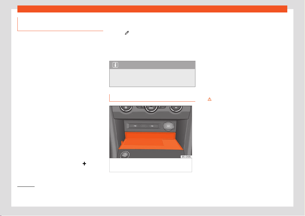
284
Infotainment system
1)
It only includes the wireless charge functionality.
2)
Qi technology allows you to charge your mobile phone wirelessly.
Phone book, favourites and speed
dial butt
ons
In the first connection of a telephone with the
infotainment system, the phone book is saved
in the infotainment system. It may be necessary
to confirm the data transmission on the mobile
phone.
Each time the phone is reconnected, the phone
book is updated.
If conference calls are supported, the phone
book can be accessed during a call. If there is a
saved image for a contact, it can be displayed
in the list next to the entry.
Favourites
A speed dial button can be assigned to a phone
book favourite up to a maximum of six. If there
is a registered photo saved to the contact, it is
shown on the speed dial button.
All speed dial buttons have to be manually
edited and will be assigned to a user profile
›››page281.
Assign the speed dial button
●
In the Favourites menu, press the
button,
then open the phone book t
o select a contact
as a favourite. If the contact has several phone
numbers, press on the number in the list.
Edit the speed dial button
●
To edit or delete a favourite contact press on
the icon
in the F
avourites menu screen. You
can delete one or more favourites.
Call a favourite
●
Press the assigned speed dial button.
Note
Favourites are not updated automatically. If
you change a cont
act's phone number, you
have to reassign the speed dial button.
Connectivity Box
Fig.192 Centr
e console: slot for mobile phone
connection.
The Connectivity Box includes dier
ent func-
tions that will help to use your mobile device.
These are:
●
Wireless Charger
1)
.
●
Signal amplifier / (Mobil
e Signal Amplifier)
Wireless charger
The Wireless Charger allows mobile devices
with Qi
2)
technology to be charged without a
cable.
To charge your mobile phone wirelessly:
●
Place your mobile device in the middle of
the pad with the scr
een facing up ›››Fig.192 ,
›››
.
Mak
e sure there are no objects between the
pad and the mobile phone.
The mobile phone will start charging automat-
ically. For further information about whether
your mobile device uses Qi technology, check
your phone's user manual or visit the SEAT
website
Mobile Signal Amplifier
It allows you to reduce radiation in the vehicle
and have better reception.
Infotainment system
285
Telephone interface
For safety reasons, it is recommended that
you pair the syst
em and the mobile using Blue-
tooth® and place it on the Connectivity Box
pad, for the best reception without having to
handle the mobile phone.
To establish a connection with the vehicle's ex-
ternal aerial:
●
Place your mobile device in the middle of
the pad with the screen facing up ›››Fig.192 ,
›››
.
Mak
e sure there are no objects between the
pad and the mobile phone.
Your mobile phone will automatically be ready
to make use of the external aerial.
WARNING
Notifications on the scr
een of the mobile de-
vice can distract the driver’s attention and
increase the risk of a serious accident.
●
Only place one suitable mobile device,
with Qi compatibility if applicable. To ensure
that it operates properly, place it without
the protective case and ensure that it has
maximum dimensions (width x length) of 80 x
140 mm (3.15 x 5.512 inches) on the base of
the Connectivity Box as indicated.
●
If the mobile device is not placed on the
base of the Connectivity Box, in the correct
position, or if its dimensions exceed those
specified, it may not be recognised or may
not charge correctly. Under certain circum-
stances, the infotainment system indicates
that there is a foreign object in the storage
compartment. Using a suitable mobile phone
device and correcting its position can elimi-
nate the fault.
●
If necessary, remove any objects that may
obstruct the cover’s closing function.
WARNING
●
The mobile phone may heat up due to the
wir
eless charging. Think about this before
you pick it up, and take care when removing
it.
●
There must be no metallic or other objects
between the mobile phone and the housing,
to prevent the functionality of the Connectiv-
ity Box from being aected.
Note
●
Your mobile device must support the Qi
inductiv
e charging interface standard for
proper operation.
●
The charging time and the temperature
vary in accordance with the device used.
●
The maximum charging capacity is 5 W.
●
Qi technology does not allow you to
charge more than one mobile device simul-
taneously.
●
No improvement in reception can be guar-
anteed if there is more than one mobile
phone on the pad.
●
You are advised to keep the engine running
to guarantee proper wireless charging.
●
When a telephone with Qi technology is
connect
ed by USB, it will be charged by the
means specified by the manufacturer.
286
Storing objects
Storing objects
P
ositioning the luggage
and cargo
General information
Placing luggage inside the vehicle safely
It is possible to carry objects and luggage in the
vehicle, in a trailer ›››page297 and on the roof
›››page295. When doing so, please consider
all legal provisions.
●
Distribute the load in the vehicle as evenly as
possibl
e.
●
Always place luggage and heavy objects as
far forwards as possible in the luggage com-
partment ›››
.
●
Take into account the maximum authorised
w
eight per axle, as well as the maximum au-
thorised weight of the vehicle ›››page382.
●
Secure the objects to the fastening rings
of the boot using appropriate chains or belts
›››page293.
●
Also place small objects safely.
●
If required. raise the rear seat backrest and
lock it.
●
In vehicles with dynamic headlight range
contr
ol, the lights adapt automatically.
●
Adapt tyre pressure to the load. Take into
account the pr
essure sticker of the tyres
›››page349.
●
In vehicles equipped with tyre pressure con-
trol system, adjust to the new load status if nec-
essary ›››page359.
WARNING
Loose or unsecured objects can cause seri-
ous injury in case of sudden manoeuvring
or br
aking or in case of an accident. Partic-
ularly if the airbag hits them when deploying
and they are thrown across the inside of the
vehicle. Please observe the following rules to
minimise the risk of injury:
●
Place all objects inside the vehicle safely.
●
Secure all objects, little and large.
●
Place the objects in the cabin in such a
way that they can never reach the airbag de-
ployment areas while the vehicle is in motion.
●
Keep the storage compartments closed at
all times while the vehicle is in motion.
●
Place the objects in such a way that they
never force any occupant of the vehicle to sit
in an incorrect position.
●
When transporting objects that take up a
seat, never let anyone use that seat.
●
Never leave hard, sharp or heavy objects
loose in open storage compartment of the
vehicle, on the cover behind the rear seat or
on the instrument panel.
●
Remove all hard, sharp or heavy objects
fr
om the fabrics and bags inside the cabin
and store them safely.
WARNING
The transport of heavy object changes vehi-
cl
e handling and increases braking distance.
Heavy objects that are not properly placed
or secured may cause loss of control of the
vehicle and thus severe injuries.
●
Never put too much load in the vehicle.
Both the carrying capacity as well as the
distribution of the load in the vehicle have
eects on the driving behaviour and braking
ability.
●
When transporting heavy objects, the driv-
ing behaviour of the vehicle varies due to the
displacement of the centre of gravity.
●
Always distribute the load in the vehicle as
evenly and horizontally as possible.
●
Always place heavy objects in the boot be-
fore the rear axle and as far away from it as
possible.
●
Objects in the luggage compartment that
are unsecured could move suddenly and
modify the handling of the vehicle.
●
Adapt your speed and driving style at all
times to suit visibility, weather, road and
trac conditions.
●
Accelerate with particular care and cau-
tion.
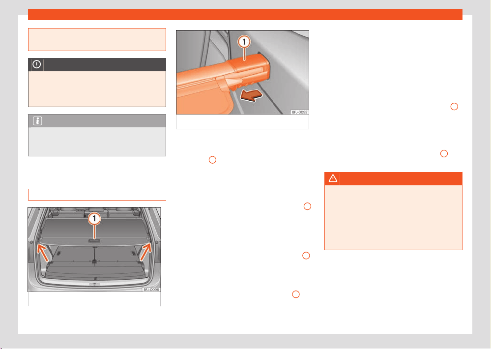
Storing objects
287
Luggage compartment
●
Avoid sudden braking and manoeuvres.
●
Brake earlier than usual.
NOTICE
Electrical wires or, depending on the fea-
t
ures, the antenna embedded into the rear
windows could be damaged, even irrepara-
bly, if they are in contact with objects.
Note
Straps for securing the load to the fasten-
ing rings are commercially available from
accessory shops.
Luggage compartment
Luggage compartment shelf
Fig.193 In the boot: shelf of the boot cl
osed.
Fig.194 In the boot: r
emoving the rear shelf.
Open the rear shelf
●
Pull the cover backwards with the handle
›››Fig.193
1
and remove it above the anchor
point (arr
ows). Move the cover forward care-
fully.
Close the rear shelf
●
Pull the cover backwards with the handle
1
and secure it to the anchor point (arrows).
R
emove the rear shelf
●
If required, open the rear shelf.
●
Press the support of the cover ›››Fig.194
1
in the direction of the arrow and hold it in this
position.
●
Then lift the cover out.
●
Remove the cover support ›››Fig.194
1
.
Depending on the equipment, once the lug-
gage compartment shelf has been r
emoved,
it can be stored under the boot's floor
›››page288.
Fit the rear shelf
●
Place the left side of the rear shelf in the
housing provided in the left side cover.
●
Press the support of the cover ›››Fig.194
1
in the direction of the arrow and hold it in this
position.
●
Place the cover in the housing provided in the
l
eft side cover.
●
Remove the cover support ›››Fig.194
1
.
●
Check that the cover is correctly secured.
WARNING
Animals, loose or unsecured or objects car-
ried on the r
ear shelf can cause serious injury
in case of sudden manoeuvring or braking or
in case of an accident.
●
Do not leave hard, sharp or heavy objects
or in bags on the rear shelf.
●
Never transport animals on the rear shelf.
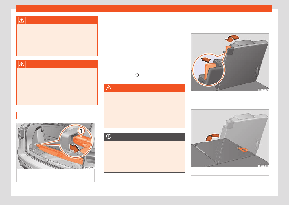
288
Storing objects
WARNING
If the rear shelf is fitt
ed in front of a rear
seat, it may cause severe injuries in the event
of sudden braking or in the event of an acci-
dent.
●
If the seats of the third row are occupied,
never fit the rear shelf before that row.
WARNING
If driving without the covers of the rear shelf
inst
alled, serious injury may happen in case
of sudden manoeuvring or braking or in case
of an accident.
●
In vehicles with 7 seats, always place the
covers on the housings of the rear shelf when
it is not fitted.
Store the rear shelf
Fig.195 Under the boot floor: st
ore the rear
shelf.
Depending on the equipment, once the lug-
gage compartment shelf has been r
emoved, it
can be stored under the boot floor.
●
Lift the luggage compartment floor
›››page290.
●
Place the rear shelf in the corresponding
housing ›››Fig.195.
●
Place the boot floor in its starting position.
If the 12-volt battery is fitted in the boot, do
not store the rear shelf under the luggage com-
partment floor›››
. If you are going to use the
thir
d row of seats, keep the cover at home.
WARNING
During a sudden driving or braking manoeu-
vr
e, or in the event of an accident, objects
could be flung though the interior and cause
serious or fatal injuries or damage to the ve-
hicle.
●
Never leave the rear shelf loose in the lug-
gage compartment.
NOTICE
If the rear shelf is stored incorrectly, it may
cause damages t
o the electrical system or
the cabin.
●
When storing the rear shelf, always make
sure it does not touch the 12-volt battery in
the boot.
Placing the third row of seats in the
car
go floor position
Fig.196 Thir
d row of seats: place the seat in
loading floor position.
Fig.197 Thir
d row of seats: lift the seat.
The rear seats can be folded down separately
t
o extend the boot.
Storing objects
289
Luggage compartment
Placing the third row of seats in loading floor
position
●
Remove the luggage compartment shelf
›››page287.
●
Push the head restraint down as far as it will
go ›››page1
12.
●
Release the seat belt from both locks to pre-
vent damages to the seat and the seat belt.
●
Move the seats of the second row fully for-
ward ›››page110.
●
Open the rear lid.
●
Remove any objects located in the footwell in
front of and behind the seat ›››
.
●
Remove objects from the space below the
corr
esponding seat.
●
Pull the unlocking lever ›››Fig.196 to its rear-
most position to unlock the seat backrest.
●
Move the backrest down with your hand un-
til it is completely against the frame of the
seat›››
.
●
When the seat is in loading floor position,
do not l
et anyone travel in it (not even a
child)›››
.
●
Close the tailgate.
Lifting the seats of the thir
d row
●
Move the seats of the second row fully for-
w
ard.
●
Open the rear lid.
●
Pull the cord on the backrest of the seat
›››Fig.196 to lift the backrest. OR: lift the back-
rest with your hand from the vehicle interior.
●
The red mark on the unlock lever ›››Fig.196
must disappear.
●
Make sure that the seat backrest is correctly
engaged by pulling and pushing it.
●
If required, fit the rear shelf again.
●
Close the tailgate.
WARNING
Risk of suering se
vere head injuries If peo-
ple taller than 1.60 m travel in the third row,
they may receive severe head injuries in the
event of an accident.
●
Never travel with anyone taller than 1.60 m
on the third row.
●
When closing the rear lid, always be mind-
ful of the passengers of the rearmost seats.
WARNING
If the rear seats are folded down or lifted
without paying att
ention or without control,
severe injuries might occur.
●
Never lower or lift the rear seat backrests
while driving.
●
Do no trap or damage the seat belt when
raising the rear seat backrests.
●
When moving the rear seat backrests up
and do
wn, keep your hands, fingers, feet and
other body parts out of the operating area of
the hinges and the locking mechanism of the
seats.
●
Mats or other objects can be caught in
the hinges of the seat backr
ests or the seats
themselves. This would cause the backrests
not to be locked correctly in an upright posi-
tion.
●
For the rear seat belts to oer the neces-
sary protection, the rear backrests must be
properly engaged vertically. If someone is
seated in a seat whose backrest is not prop-
erly engaged they will be thrown forwards,
along with the backrest, during an accident
or a sudden driving or braking manoeuvre.
●
A red mark on unlock lever ›››Fig.196 in-
dicates that backrest is not engaged. If the
back rest is locked correctly, the mark is not
visible.
●
When a rear seat or its backrest is folded
down or not correctly engaged, do not let
anyone use that seat (not even a child).
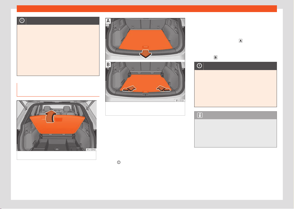
290
Storing objects
NOTICE
●
Objects placed in the footwell in front of
and behind the r
ear seats can be damaged
when seats are folded down or lifted. Before
folding down or lifting the seats, remove the
objects.
●
Any objects located in the footwell behind
the third row of seats may be damaged on
folding or lifting the seats of this row. Before
folding down or lifting the seats, remove the
objects.
Adjustable luggage compartment
floor (5-seater vehicles)
Fig.198 In the boot: lift the boot floor
.
Fig.199 In the boot: adjust the v
ariable boot
floor.
Open boot floor
●
Use the handle ›››Fig.198 t
o lift the luggage
compartment floor upwards in the direction of
the arrow.
Close boot floor
●
Move the floor down carefully and let it
go›››
.
Adjust the height of the v
ariable boot floor
Depending on the features, the height of the
boot floor can be adjusted.
●
If necessary, release the net bag and remove
the attachment or support straps if applicable.
●
Lift the boot floor and pull it backwards to
release it from the side guides of the luggage
compartment ›››Fig.199
.
●
Place the floor on the guides of the desir
ed
height and move it forwards as far as possible
›››Fig.199
.
NOTICE
●
Do not tug the boot floor suddenly when
opening or l
et it fall down when closing. Oth-
erwise, the lining and the floor of the boot
could be damaged.
●
The maximum weight that can be loaded
on the luggage compartment variable floor
in the top position is 125 kg.
Note
●
Depending on the features, there are stor-
age compar
tments for small objects under
the boot floor.
●
SEAT recommends the use of fastening
straps to secure objects to retaining rings.
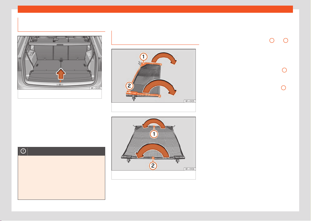
Storing objects
291
Net partition
Luggage compartment floor (
7-
seater vehicles)
Fig.200 In the boot: lift the boot floor
.
Open boot floor
Gr
ab the boot floor by the cord ›››Fig.200 and
lift it in the direction of the arrow and remove it.
Close boot floor
●
Place the boot floor on the support and care-
fully lower it.
NOTICE
●
Do not let the luggage compartment floor
f
all when closing it. Always carefully guide
it downward in a controlled manner. Other-
wise, the lining and the floor of the boot
could be damaged.
●
The maximum weight that can be loaded
on the luggage compartment variable floor
in the top position is 125 kg.
Net partition
Unf
olding and folding the net parti-
tion
Fig.201 Depl
oying the net partition.
Fig.202 F
olding in the net partition.
Before fitting the net partition in the v
ehicle it
must be unfolded.
Fold out the net partition
●
Take out the partition net from the corre-
sponding bag and unr
oll it.
●
Extend the cross rods ›››Fig.201
1
and
2
of the net in the direction of the arrows until a
“
clicks” is heard.
Folding in the net partition
●
Press on the release button ›››Fig.202
1
and bend the cross rod in the direction of the
arr
ow with the button pressed.
●
Press on the release button ›››Fig.202
2
and bend the cross rod in the direction of the
arr
ow with the button pressed.
●
Fold in the net partition and store it in its bag.
●
Store the net partition safely in the vehicle.
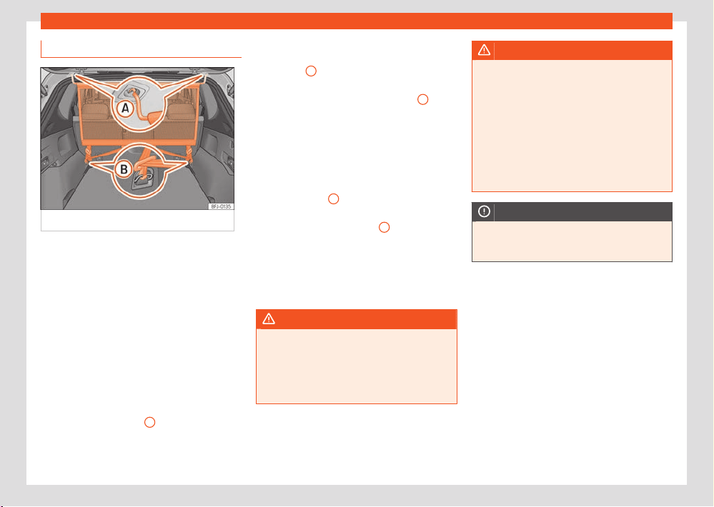
292
Storing objects
Using the net partition
Fig.203 Net partition fitt
ed.
The purpose of the net partition is to prevent
the it
ems in the boot from moving into the cabin,
e.g. in the event of sudden braking.
Fitting the net partition
The partition net can be fitted behind the rear
seat or, depending on the features, behind the
front seats with the second row of seats low-
ered.
●
If required, remove the rear shelf
›››page287.
●
Folding out the net partition.
●
Hook the net partition to the left-hand side
roof housing ›››Fig.203
A
.
Be sur
e to pull the cross rod down past the up-
per position.
●
Hook in the net partition on the rear right-
hand side r
oof housing by pressing on the bar
›››Fig.203
A
.
●
Secure two hooks of the partition net to the
f
astening rings of the boot ›››Fig.203
B
and
tight
en the straps firmly.
Removing the net partition
●
If required, remove the rear shelf.
●
Loosen the straps from the net partition.
●
Release the net hooks from the fastening
rings ›››Fig.203
B
.
●
Unhook the net partition on the right-hand
side r
oof support ›››Fig.203
A
by pressing
on the cr
oss rod.
●
Unhook the net partition from the left-hand
side roof housing.
●
Fold in the net partition.
●
If required, fit the rear shelf.
WARNING
In order to ensure the proper functioning of
the luggage r
estraint systems (backrests to-
gether with the net partition), place the sec-
ond row of seats in their rearmost position to
avoid the possibility of the load on top mov-
ing forward. Risk to vehicle occupants.
WARNING
During a sudden driving or braking manoeu-
vr
e, or in the event of an accident, objects
could be flung though the interior and cause
serious or fatal injuries.
●
Check whether the cross rods are cor-
rectly engaged.
●
Always secure objects, even when the net
partition is properly assembled.
●
There should be nobody behind the net
partition when the vehicle is moving.
NOTICE
If the net partition is secured incorrectly or
t
o incorrect points, this may damage the ve-
hicle.
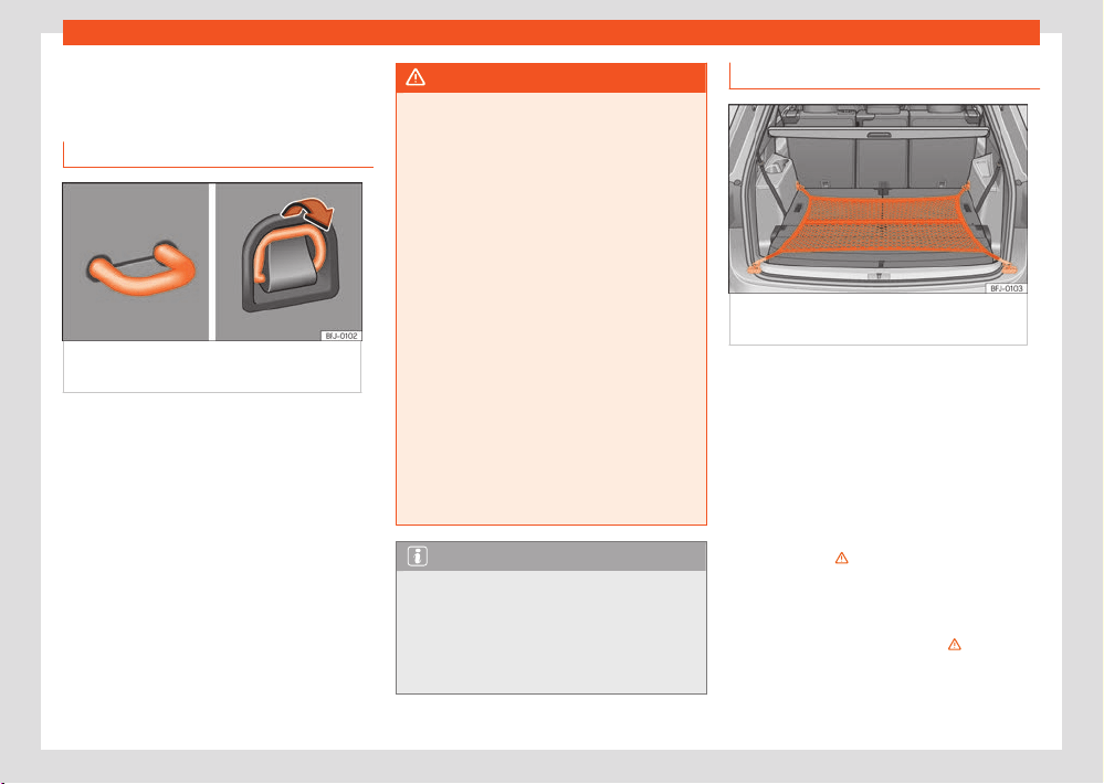
Storing objects
293
Luggage compartment equipment
Luggage compartment
equipment
F
astening rings
Fig.204 In the luggage compartment:
f
astening rings.
There are fastening rings ›››Fig.204 on the
fr
ont and rear of the boot to secure loose
objects and luggage with fastening belts and
cords.
WARNING
If unsuitable or damaged belts or retaining
str
aps are used, they could break in the
event of braking or an accident. Objects
could then be launched across the passen-
ger compartment and cause serious or fatal
injuries.
●
Always use belts or straps that are suitable
and in good condition.
●
Tighten the belts and straps in a cross
layout over the load placed on the boot
floor and secure them to the fastening rings
safely.
●
Never exceed the maximum tensile load of
the fastening rings when securing objects.
●
Make sure that, particularly for flat ob-
jects, the upper edge of the load is higher
than the fastening rings.
●
Depending on the features, take into ac-
count the instruction panels on the boot on
how to place the load.
●
Never secure a child seat to the fastening
rings.
Note
●
The maximum tensile load that the fasten-
ing rings can suppor
t is approx. 3.5 kN.
●
Belts, straps and securing systems for the
appropriate load can be obtained from spe-
cialised dealerships. SEAT recommends visit-
ing a SEAT dealership for this.
Net bag
Fig.205 In the boot: net bag hook
ed up at
floor level.
The luggage compartment prevents light lug-
gage fr
om moving. The net bag has a zip and
can be used to store small objects.
Hooking the net bag into the luggage com-
partment floor
If necessary, the front eyes must be unfolded
first ›››page293.
●
Secure the net hooks to the fastening rings
›››Fig.205 , ›››
. The bag zip should be
f
acing upwards.
Removing the net bag
The hooked up net bag is taut›››
.
●
Release the net bag from the fastening rings.
●
Store the net bag in the luggage compart-
ment.
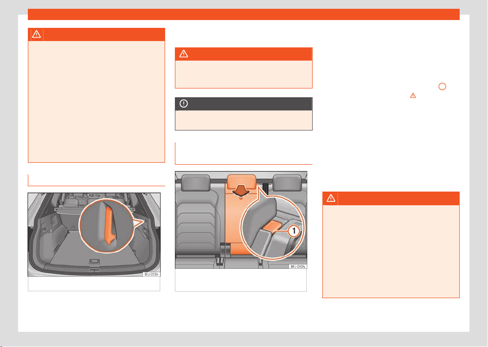
294
Storing objects
WARNING
To secure the elastic net bag on the fasten-
ing rings of the boot it must be str
etched out.
Once hooked up it is taut. If the net bag is
hooked up or unhooked incorrectly the hooks
could cause injuries.
●
Always secure the bag hooks properly so
that they do not suddenly release from the
fastening rings when hooking or unhooking
them.
●
On hooking or unhooking them, protect
your eyes and face in case the hooks are
released suddenly.
●
Always hook up the net bag hooks in the
described order. If a hook comes loose
Bag hooks
Fig.206 In the boot: r
etaining hooks.
There may be hooks for hanging bags on both
sides of the luggage compartment ›››Fig.206.
The retaining hooks have been designed to se-
cur
e light shopping bags.
WARNING
Never use the hooks to hang luggage or
other ob
jects. In case of sudden braking or
an accident, the hooks could break.
NOTICE
Each hook is designed for a maximum load of
2.5 k
g.
Trapdoor for transporting long ob-
jects
Fig.207 R
ear seat backrest: opening the
tailboard for long objects.
Depending on the features, on the rear seat,
behind the centr
al armrest, there is a tailboard
for transporting long items in the interior, such
as skis.
Opening the tailboard for long items
●
Press the unlocking button ›››Fig.207
1
and
f
old the tailboard forwards›››
.
●
Open the rear lid.
●
Insert the long objects through the tailboard
fr
om the luggage compartment.
●
Secure the objects with the seat belt firmly.
●
Close the tailgate.
Closing the tailboard for long items
●
Lift the seat back and press it firmly into the
lock until it engages correctly.
WARNING
Serious injuries can be caused if the tail-
boar
d for long items is lowered or lifted with-
out due care and attention.
●
Never lower or lift the tailboard while driv-
ing.
●
Do no trap or damage the seat belt when
raising the tailboard.
●
When lowering or lifting the tailboard, keep
your hands, fingers, feet and other body
parts out of its path.
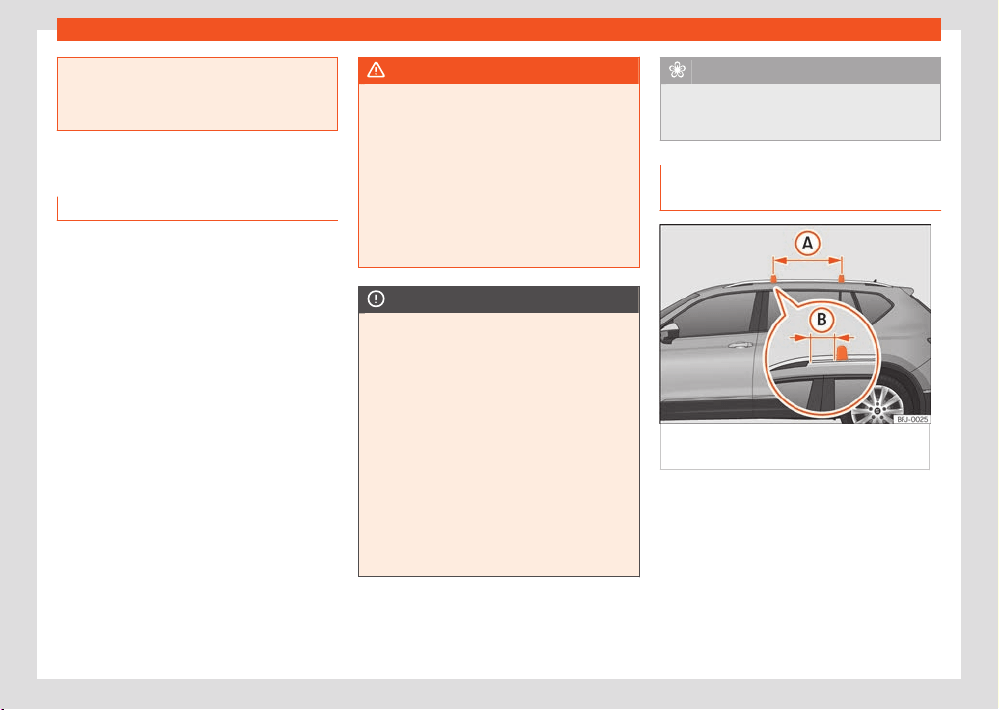
Storing objects
295
Roof carrier
●
When the tailboard is lowered or is not
pr
operly engaged nobody else can travel
in the corresponding seats, particularly chil-
dren.
Roof carrier
Introduction
The vehicle roof has been designed to optimise
aerodynamics. For this reason, cross bars or
conventional roof carrier systems cannot be
secured to the roof water drains.
As the roof water drains are integrated in the
roof to reduce air resistance, only SEAT-ap-
proved cross bars and roof carrier systems can
be used.
Cases in which cross bars and the roof car-
rier system should be disassembled.
●
When they are not used.
●
When the vehicle is washed in a car wash.
●
When the vehicle height exceeds the maxi-
mum height, f
or example, in some garages.
WARNING
●
Always secure the load properly using
belts or r
etaining straps that are suitable and
in a good condition.
●
Bulky, heavy, long or flat loads have a neg-
ative eect on aerodynamics, the centre of
gravity and driving performance.
●
Avoid sudden braking and manoeuvres.
●
Adapt your speed and driving style at all
times to suit visibility, weather, road and
trac conditions.
NOTICE
●
Remove the cross bars and the roof carrier
syst
em before entering a car wash.
●
Vehicle height is increased by the installa-
tion of cross bars or a roof carrier system
and the load secured on them. For this pur-
pose, check that your vehicle's height does
not surpass the headspace limit, for exam-
ple, for underpasses or for entering garage
doors.
●
Cross bars, the roof carrier system and the
load secured on them should not interfere
with the roof aerial or hamper the path of the
panoramic sun roof and the rear lid.
●
On opening the rear lid make sure that it
does not knock into the roof load.
For the sake of the environment
When cross bars and a roof carrier system
ar
e installed, the increased air resistance
means that the vehicle uses more fuel.
Securing the crossbars and the roof
carrier system
Fig.208 Att
achment points for the roof
railings for the roof carrier
The crossbars are the basis of a series of spe-
cial r
oof carrier systems. For safety reasons,
special fixtures must be used to safely transport
luggage, bicycles, skis, surf boards or boats on
the roof. Suitable accessories can be acquired
at SEAT dealerships.
296
Storing objects
Always secure the crossbars and the roof car-
rier syst
em properly. Always take the assembly
instructions that come with the crossbars and
the roof carrier system in question into account.
Installing the bars
The crossbars are assembled on the roof
railings. The distance between crossbars
›››Fig.208
A
should be between 75 and
90 cm and the dist
ance between the crossbars
and the brackets of the roof railings
B
must be
15cm.
WARNING
Incorrect attachment and use of the cross-
bars and the r
oof carrier system may cause
the whole system to detach from the roof
and cause an accident and injuries.
●
Always take the manufacturer assembly
instructions into account.
●
Check threaded joints and attachments
travelling and if necessary tighten them after
you have travelled a short distance. When
making long trips, check the threaded joints
whenever you stop for a rest.
●
Do not modify or repair the crossbars or
roof carrier system.
Note
Always read the assembly instructions that
come with the cr
ossbars and the roof carrier
system carefully and keep them in the vehi-
cle.
Loading the roof carrier system
The load can only be secured if the crossbars
and the roof carrier system are properly instal-
led›››
.
Maximum authorised car
go on the roof
The maximum permissible roof load is 75 kg.
This figure comes from the combined weight
of the roof carrier, the cross bars and the load
itself on the roof ›››
.
Al
ways check the weight of the roof carrier
system, the cross bars and the weight of the
load to be transported and weigh them if nec-
essary. Never exceed the maximum authorised
roof load.
If you are using cross bars and a roof carrier
with a lower weight rating, you will not be able
to carry the maximum authorised roof load. In
this case, do not exceed the maximum weight
limit for the roof carrier which is listed in the
fitting instructions.
Distributing a load
Distribute loads uniformly and secure them cor-
rectly ›››
.
Check attachments
Once the cr
oss bars and roof carrier system
have been installed, check the bolted connec-
tions and attachments after a short journey and
subsequently with a certain frequency.
WARNING
●
Never exceed the maximum authorised
l
oad on the roof and on the axles or the ve-
hicle's maximum authorised weight.
●
Never exceed the load capacity of the
cross bars and the roof carrier system, even
if the maximum authorised roof load has not
been reached.
●
Secure heavy items as far forward as
possible and distribute the vehicle load uni-
formly.
WARNING
If the load is loose or not secured, it could
f
all from the roof carrier system or cause ac-
cidents and injuries.
●
Always use belts or retaining straps that
are suitable and in a good condition.

Storing objects
297
Trailer mode
Trailer mode
Intr
oduction
Take into account country-specific regulations
about driving with a trailer and the use of a
towing bracket.
The vehicle has been developed primarily for
carrying people, although it can also be used
to tow a trailer if fitted with the corresponding
technical equipment. This additional load has
an eect on the useful life, fuel consumption
and vehicle performance and in some cases
can reduce the service intervals.
Driving with a trailer requires more force from
the vehicle, and thus more concentration from
the driver.
In winter, winter tyres should be fitted on both
the vehicle and the trailer.
Maximum vertical load technically permit-
ted on the coupling device
The maximum vertical load technically permit-
ted from the trailer draw bar on the towing
bracket's tow ball is 100 kg.
Vehicles with the Start-Stop system
If the vehicle has a factory-fitted towing
bracket or one that is retrofitted by SEAT, the
Start-Stop system operates as normal. No spe-
cial characteristics need to be taken into ac-
count.
If the system does not recognise the trailer or
the trailer bracket has not been retrofitted by
SEAT, the Start-Stop system must be discon-
nected by pressing the corresponding button
in the lower part of the centre console before
driving with the trailer, and it should remain o
for the rest of the journey›››
.
V
ehicles with driving profile selection
If you are going to be towing a trailer, the use of
the Eco driving profile is not recommended. You
are advised to select another of the available
driving profiles before beginning to drive with a
trailer.
Trailer weight/drawbar load
Never exceed the authorised trailer weight. If
you do not load the trailer up to the maximum
permitted trailer weight, you can then climb
correspondingly steeper slopes.
The maximum trailer weights listed are only ap-
plicable for altitudes up to 1000 m above sea
level. Since higher altitude decreases engine
performance and the ability to climb slopes, the
tow load decreases proportionally. The weight
of the vehicle and trailer combination must be
reduced by 10% for every 1000 m of altitude.
When possible, operate the trailer with the max-
imum authorised drawbar load on the ball
joint of the towing bracket, but do not exceed
the specified limit.
WARNING
Never use the trailer to transport people,
since it w
ould put their life in danger and is
also prohibited.
WARNING
Undue use of the towing bracket may cause
injury and accidents.
●
Only use the towing bracket if it is in a per-
f
ect state of repair and is properly secured.
●
Never modify or repair the towing bracket
in any way.
●
In order to reduce the danger of injury in
the event of rear-end collisions and to avoid
injury to pedestrians and cyclists when park-
ing the vehicle, cover or remove the tow hook
when you are not using a trailer.
●
According to EU regulation 2021_535 it is
not permitted to install a towing device that
completely or partially covers the rear num-
ber plate.
●
Never fit a towing bracket “with weight dis-
tribution” or “load compensation”. The vehi-
cle has not been designed for this type of
towing bracket. The towing bracket could fail
and the trailer could be released from the
vehicle.
298
Storing objects
WARNING
Driving with a trailer and transporting heavy
or l
arge objects can aect driving properties
and even cause an accident.
●
Always secure the load properly using
belts or straps that are suitable and in good
condition.
●
Adapt your speed and driving style at all
times to suit visibility, weather, road and
trac conditions.
●
Trailers with a high centre of gravity are
more likely to overturn than those with a low
one.
●
Avoid sudden braking and manoeuvres.
●
Take great care when overtaking.
●
Reduce speed immediately if you notice
that the trailer is swaying, however slightly.
●
Never drive at more than 80km/h (50mph)
when towing a trailer (or at more than
100 km/h (60 mph) in exceptional circum-
stances). This also applies in countries where
driving at higher speeds is permitted. Take
into account the speed limit for vehicles with
trailers in the corresponding country, as it
could be less than the speed limit for vehi-
cles without a trailer.
●
Never attempt to “straighten” the towing
vehicle and trailer while accelerating.
WARNING
If the towing bracket has been r
etrofitted by
a non-SEAT workshop, the Start-Stop system
must be disconnected manually whenever
driving with a trailer. Otherwise the brake
system could be damaged and could conse-
quently cause a serious accident or injury.
●
Always disconnect the Start-Stop system
manually when using a towing bracket that
has not been fitted by a SEAT workshop.
Note
●
Before hitching or unhitching a trailer,
al
ways deactivate the anti-theft alarm
›››page90. Otherwise, the tilt sensor could
cause the alarm to go o.
●
Do not drive with a trailer for the engine's
first 1000km ›››page148.
●
Some retrofitted towing brackets cover the
rear towing eye. In these cases, the towing
eye should not be used for tow-starting or
for towing other vehicles. For this reason, if
the vehicle has been retrofitted with a towing
bracket, always keep the tow hook in the ve-
hicle when you remove it.
Technical requirements
Vehicles that are factory-equipped with a tow-
ing bracket fulfil all the technical and legal re-
quirements for driving with a trailer.
If the v
ehicle is retrofitted with a tow bracket,
only a bracket that is authorised for the max-
imum authorised load of the trailer that is to
be towed may be fitted. The towing bracket
must be suitable for the vehicle and the trailer
and must be properly secured to the vehicle's
chassis. Only use a towing bracket that has
been authorised by SEAT for this vehicle. Al-
ways check and take into account the towing
bracket manufacturer's instructions.
Towing bracket fitted on the bumper
Never fit a towing bracket to the bumper or to
the area where the bumper is mounted. The
towing bracket should not impair the bumper's
function. Do not make modifications or repairs
to the exhaust system or the brake system.
Make regular checks to ensure that the towing
bracket is secure.
Engine cooling system
Driving with a trailer increases the load on the
engine and cooling system. The cooling system
should have sucient coolant and be prepared
for the additional eort involved in driving with
a trailer.
Trailer brakes
If the trailer has its own brake system, please
take the relevant legal requirements into ac-
count. Never connect the trailer's brake system
to the vehicle's brake system.
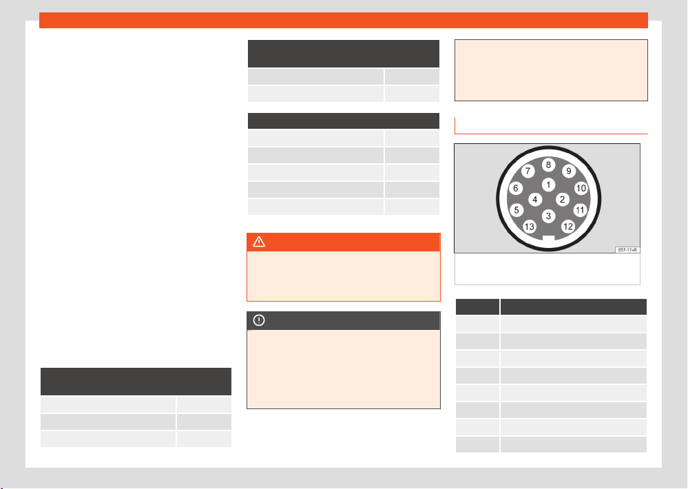
Storing objects
299
Trailer mode
Tow cable
Al
ways use a cable between the vehicle and
the trailer ›››page299.
Trailer tail lights
The trailer's rear lights should comply with the
statutory safety regulations ›››page299.
Never connect the trailer's rear lights directly
to the vehicle's electric system. If you are not
sure that the trailer's electrical connection is
correct, have it checked by a specialised work-
shop. SEAT recommends visiting a SEAT dealer-
ship for this.
Exterior mirrors
If you cannot see the area behind the trailer
with the exterior mirrors of the towing vehicle,
additional mirrors will have to be installed in
accordance with the regulations of the country
in question. The exterior mirrors should be ad-
justed before you start driving and must provide
a sucient field of vision at the rear.
Trailer maximum electricity consumption
Never exceed the values indicated!
Europe, Asia, Africa, South America and Cen-
tral America
Brake lights (total) 84 Watts
Turn signal (on each side) 42 Watts
Side lights (on each side) 50 Watts
Europe, Asia, Africa, South America and Cen-
tral America
Reverse lights (in total) 42 Watts
Rear fog light 42 Watts
Australia
Brake lights (total) 108 Watts
Turn signal (on each side) 54 Watts
Side lights (on each side) 100 Watts
Reverse lights (in total) 54 Watts
Rear fog light 54 Watts
WARNING
If the towing bracket is wrongly fitt
ed or is
not the right one, the trailer could become
detached from the vehicle and cause serious
injury.
NOTICE
●
If the rear lights of the trailer are not
corr
ectly connected, the vehicle's electronic
system may be damaged.
●
If the trailer absorbs excessive electric cur-
rent, the vehicle's electronic system may be
damaged.
●
Never connect the trailer's electric system
dir
ectly to the electrical connections of the
tail lights or any other power sources. Only
use the connections intended for providing
electric current to the trailer.
Hitching and connecting a trailer
Fig.209 Diagr
am: assignment of the pins of
the trailer's electrical socket.
Pin Meaning
1 Left turn signal
2 Rear fog light
3 Earth for pins 1, 2, 4, 5, 6, 7 and 8
4 Right turn signal
5 Rear light, right
6 Brake lights
7 Rear light, left
8 Reverse lights

300
Storing objects
Pin Meaning
9 Permanent live
10 Live charge cable
11 Earth for pin 10
12 Unassigned
13 Earth for pin 9
Power socket for trailer
The v
ehicle is fitted with a 13-pole power socket
for the connection between the trailer and the
vehicle. With the engine running, electrical devi-
ces on the trailer receive power from the elec-
trical connection (pin 9 and pin 10 of the trailer
power socket).
If the system detects that a trailer has been
connected, the consumers on the trailer will re-
ceive electricity through this connection (pins 9
and 10). Pin 9 has a permanent live. This pow-
ers, for example, the trailer's interior lighting.
Electrical devices such as a fridge in a caravan
only receive electrical power if the engine is
running (through pin 10).
To avoid overloading the electrical system, you
cannot connect the ground wires of pin 3, pin 11
or pin 13.
If the trailer has a 7-contact connector, you
will need to use an adapter cable. In this case
the function corresponding to pin 10 will not be
available.
Tow cable
The tow rope must always be securely fixed to
the towing vehicle and loose enough so that the
vehicle can handle turns smoothly. However,
make sure that the cable does not rub on the
ground while driving.
Trailer tail lights
Always check the trailer's rear lights to ensure
they are working correctly and that they com-
ply with the relevant safety regulations. Make
sure that the maximum permissible power that
can be absorbed by the trailer is not exceeded
›››page298.
Include in the anti-theft alarm
The trailer is included in the anti-theft system if
the following conditions are met:
●
If the vehicle is factory-equipped with an
anti-theft alarm.
●
If the vehicle is factory-equipped with a tow
bracket.
●
If the trailer is electrically connected to the
towing vehicle through the trailer power socket.
●
If the electrical systems of the vehicle and
trailer are in perfect condition and have no
faults or damage.
●
If the vehicle is locked with the key and the
anti-theft alarm is activated.
When the vehicle is locked, the alarm is trig-
gered if the electrical connection with the
trailer is cut o.
Before hitching or unhitching a trailer, always
turn o the anti-theft alarm. Otherwise, the tilt
sensor could cause the alarm to go o.
Trailers with LED tail lights
For technical reasons, trailers fitted with LED
rear lights cannot be connected to the anti-
theft alarm system.
When the vehicle is locked, the alarm does not
go o when the electrical connection with the
trailer is cut if it has rear lights with light-emit-
ting diodes.
If the Eco driving profile was selected when
hitching the trailer, this will automatically switch
to theNormal profile. If the system cannot de-
tect the attached trailer or if the towing bracket
has been retrofitted by an auto repair shop
other than SEAT, you must manually select the
Normal profile before you start driving with a
trailer attached. To reconnect the Eco profile
once the trailer has been unhitched, switch the
ignition o and back on once.
Storing objects
301
Trailer mode
WARNING
If the cables are improperly or incorrectly
connect
ed, it may lead to an excessive
amount of current supplied to the trailer,
which can cause abnormalities in the entire
vehicle electronic system, as well as acci-
dents and serious injuries.
●
Ensure that any repairs that need to be
carried out on the electrical system are car-
ried out by a specialised workshop.
●
Never connect the trailer's electric system
directly to the electrical connections of the
tail lights or any other power sources.
WARNING
Contact between the pins of the trailer
po
wer socket can cause short circuits, over-
loading of the electrical system or failure of
the lighting system, and consequently can
cause accidents and serious injuries.
●
Never connect the pins of the trailer power
socket to each other.
●
Make sure any work on bent pins is carried
out by a specialised workshop.
NOTICE
Do not leave the trailer connected to the ve-
hicl
e when parked; place it on its support
wheel or its supports. If the vehicle rises or
falls due, for example, to a variation of the
load or a burst tyre, increased pressure will
be placed on the towing bracket and the
trailer, and both the vehicle and the trailer
can be damaged.
Note
●
In case of anomalies in the electrical sys-
t
ems of the vehicle or trailer, as well as in the
anti-theft alarm system, have them inspec-
ted by a specialised workshop.
●
If the trailer accessories consume energy
through the power socket to the trailer and
the engine is turned o, the battery will dis-
charge.
●
If the vehicle battery is running low, the
electrical connection with the trailer will be
automatically cut.
Trailer loading
T
echnically permissible maximum trailer
weight and vertical load on the coupling de-
vice
The technically permissible maximum trailer
weight is the weight that the vehicle can tow
›››
. The vertical load on the coupling is ex-
ert
ed vertically from above on the hook of the
towing bracket.
The information on the maximum trailer weight
and vertical load on the coupling device con-
tained in the type plate of the towing bracket
are experimental values only. The correct fig-
ures for your specific model, which may be
lower than these figures, are given in the vehicle
documentation. The information in the vehicle
documentation takes precedence at all times.
To promote safety while driving, SEAT recom-
mends making the most of the maximum ver-
tical load technically permissible on the cou-
pling device ›››page297. An insucient ver-
tical load has a negative influence on the be-
haviour of both the vehicle and trailer.
The vertical load increases the weight on the
rear axle, reducing the vehicle's carrying ca-
pacity.
302
Storing objects
Gross combination weight of the towing ve-
hicl
e and trailer
The gross combination weight is the actual
weight of the loaded vehicle plus the actual
weight of the loaded trailer.
In some countries trailers are classified into
distinct categories. SEAT recommends obtain-
ing information from a specialised workshop re-
garding which type of trailer is most suitable for
your vehicle.
Trailer loading
The weight of the towing vehicle and trailer
must be balanced. In order to do this, the load
must be as close as possible to the maximum
vertical load technically permissible on the
coupling point, and it must be evenly distributed
between the back and front of the trailer:
●
Distribute loads in the trailer so that heavy
objects are as near to the axle as possible or
above it.
●
Secure the trailer load properly.
Tyre pressure
Set the tyre pressure of the trailer tyres in ac-
cordance with the trailer manufacturer's rec-
ommendations.
When towing a trailer, inflate the tyres of the
towing vehicle with the maximum allowable
pressure ›››page349.
WARNING
If the maximum permissible axle weight, the
maximum l
oad technically permissible on the
coupling point, the maximum authorised ve-
hicle weight or the gross combination weight
of the towing vehicle and trailer are excee-
ded, accidents and serious injuries may oc-
cur.
●
Never exceed the indicated values.
●
The actual weight on the front and rear
axles must never exceed the maximum per-
missible axle weight. The weight on the front
and rear axles must never exceed the maxi-
mum permissible weight.
WARNING
A shift in weight could jeopardize the stability
and securit
y of the towing vehicle and trailer,
which could lead to accidents and serious
injuries.
●
Always load the trailer correctly.
●
Always secure the load properly using
belts or straps that are suitable and in good
condition.
Driving with a trailer
Adjusting the headlights
The front part of the vehicle may be raised
when the trailer is connected and the light may
dazzle the rest of the trac.
Specific f
eatures of driving with a trailer
●
If your trailer has an overrun brake, brake
gently at first and then rapidly. This will prevent
the jerking that can be caused by the locking of
trailer wheels.
●
Due to the gross combination weight of the
towing vehicle and trailer, the braking distance
increases.
●
When going down a slope, engage a lower
gear (with a manual gearbox, or use the auto-
matic gearbox's tiptronic mode) to use engine
braking. Otherwise, the brake system could
overheat and even fail.
●
The trailer weight, as well as the gross combi-
nation weight of the towing vehicle and trailer,
change the centre of gravity and the properties
of the vehicle.
●
If the towing vehicle is empty and the trailer
is loaded, then the load distribution is incorrect.
Under these conditions, drive slowly and with
extra caution.
Hill starts with a trailer
Depending on the slope of the hill and the
combination weight of the towing vehicle and
trailer, the vehicle might start rolling backwards
slightly when you first start up.
For hill starts with a trailer hitched:
●
Press and hold the brake pedal.
●
Press the
button to disconnect the elec-
tr
onic parking brake ›››page207.
Storing objects
303
Trailer mode
●
Manual gearbox: Depr
ess the clutch pedal
fully and engage 1st gear.
Automatic gearbox: Move the selector lever to
the D/S position.
●
Pull out the
button and hold it in that posi-
tion t
o stop the towing vehicle and trailer with
the electronic parking brake.
●
Release the brake pedal.
●
Move o slowly.
Manual transmission: release the clutch pedal
slowly.
●
Do not release the
button until the engine
has sucient po
wer to start driving.
WARNING
If a trailer is pulled incorrectly, this may lead
t
o loss of control of the vehicle and serious
injury.
●
Driving with a trailer and transporting
heavy or large objects will change the vehi-
cle handling and braking distances.
●
Always drive cautiously and carefully.
Brake earlier than usual.
●
Adapt your speed and driving style at all
times to suit visibility, weather, road and
trac conditions. Slow down, especially
when driving down hills or slopes.
●
Accelerate with particular care and cau-
tion. Avoid sudden braking and manoeuvres.
●
Take great care when overtaking. Reduce
speed immediately if you notice that the
trailer is swaying, however slightly.
●
Never attempt to “straighten” the towing
vehicle and trailer while accelerating.
●
Take into account the speed limit for vehi-
cles with a trailer, as it could be lower than
for vehicles without a trailer.
Stabilisation of the towing vehicle
and trailer combination
The stabilisation of the vehicle and trailer com-
bination is an additional function of the elec-
tronic stability control (ESC).
If the system detects that the trailer is weaving,
it intervenes to reduce the swaying of the trailer.
Vehicle and trailer combination stabilisation
requirements
●
The vehicle is factory-equipped with a tow-
ing br
acket or has been retro-fitted with a com-
patible towing bracket.
●
The ESC and TCS are active. The control
lamp
or is not lit up on the instrument clus-
t
er.
●
The trailer is connected to the towing vehicle
through the trailer power socket.
●
The vehicle is travelling at over 60km/h (ap-
prox. 37mph).
●
The maximum vertical load technically per-
missibl
e is not being exceeded on the coupling
device.
●
The trailer has a rigid draw bar.
●
If the trailer has brakes, it must be equipped
with a mechanical overrun brake.
WARNING
The enhanced safety provided by the elec-
tric st
ability control of the vehicle and trailer
should not lead you to take any risks that
could compromise your safety.
●
Adapt your speed and driving style at all
times to suit visibility, weather, road and
trac conditions.
●
Accelerate with caution when the road is
slippery.
●
When adjusting any settings, stop acceler-
ating.
WARNING
The electric stability control for the vehicle
and tr
ailer may not correctly detect all driv-
ing conditions.
●
When the ESC is switched o, the stabili-
sation of the towing vehicle and trailer is also
switched o.
●
The stability system does not always de-
tect light trailers, so it may not stabilise
these correctly.
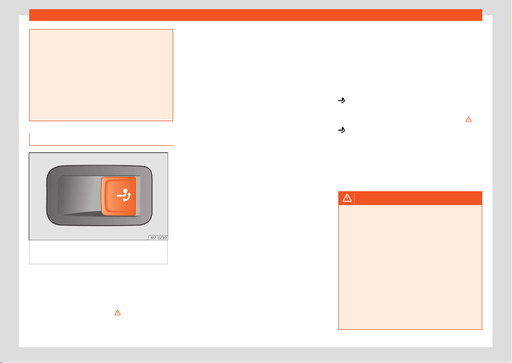
304
Storing objects
●
When driving on surfaces with poor grip,
the tr
ailer can even interfere with the stabil-
ity system.
●
Trailers with a high centre of gravity can tip
over without having previously weaved.
●
If a trailer is not attached, but a connector
is plugged into the power socket (e.g. instal-
lation of a bicycle rack with lights), repea-
ted automatic braking may occur in extreme
driving conditions.
Electrically unlocking trailer hook
Fig.210 Right side of the luggage
compartment: butt
on to unlock the tow hitch.
The towing bracket’s hook is located in the
bumper
. Tow hooks for electrical unlocking
cannot be removed.
There should be no person, animal or object in
the path of the tow hook›››
.
Unlocking the tow hook and removing it
●
Stop the vehicle and connect the electronic
parking br
ake ›››page207.
●
Switch o the engine.
●
Open the rear lid.
●
Pull the ›››Fig.210 button briefly. The
tow hook unlocks electrically and automati-
cally turns outwards. The button's control lamp
flashes.
●
Finish remove the tow hook by hand until you
feel and hear that it has engaged and the con-
trol lamp on the button stays on.
●
Close the rear lid.
●
Hitching and connecting a trailer
›››page299.
Retracting the tow hook
●
Stop the vehicle and apply the electronic
parking brake.
●
Switch o the engine.
●
Unhook the trailer and interrupt the electrical
connection between it and the vehicle. If you
are using an adapter, remove it from the trailer's
power socket.
●
Open the rear lid.
●
Pull the ›››Fig.2
10 button briefly. The tow
hook unlocks electrically.
●
Turn the tow hook under the bumper with your
hand until you f
eel and hear that it engages
and the control lamp on the button remains on
continuously.
●
Close the rear lid.
The button's control lamp
Flashing:
This means that the tow hook has not yet
engaged correctly or is damaged ›››
.
R
emains on:
If it remains on while the rear lid is open, the
tow hook is correctly in place both when
extracted and when covered.
The button's indicator lamp switches o ap-
proximately 1 minute after closing the rear lid.
WARNING
Undue use of the towing bracket may cause
injury and accidents.
●
Only use the tow hook if it is properly en-
gaged.
●
Always ensure that no person, animal or
ob
ject is to be found in the path of the tow
hook.
●
Never use a tool or instrument while the
tow hook is moving.
●
Never press the button ›››Fig.210 when
there is a trailer hooked to the vehicle or
when a carrier system or other accessories
are mounted on the tow hook.
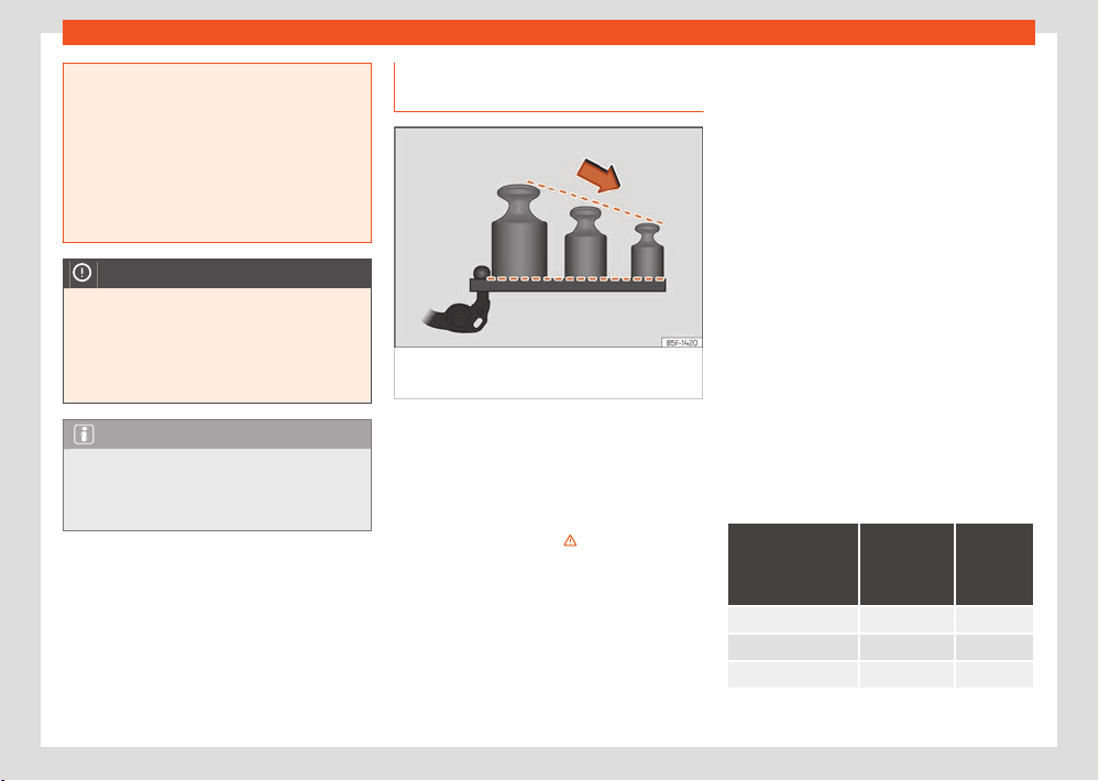
Storing objects
305
Trailer mode
●
If the tow hook is not attached properly, do
not use it. Inst
ead, go to a specialised work-
shop and have the towing bracket checked.
●
If you detect any fault in the electrical sys-
tem or in the towing bracket, contact a speci-
alised workshop and ask them to check it.
●
If the ball has a diameter of less than
49 mm at any one point, do not use the tow-
ing bracket under any circumstances.
NOTICE
If you clean the vehicle with high-pressure
or st
eam devices, do not point the jet di-
rectly towards the retractable tow hook or
the trailer power socket, as this may damage
the joints or remove the grease necessary for
lubrication.
Note
At extremely low temperatures, the tow hook
may be impossible to operate. In this case,
place the vehicle in a warmer location (for
example, a garage).
Installing a rear carrier system or a
bicycl
e rack on the trailer hitch
Fig.211 R
ecommended weight distribution on
the rear support system.
Examples of rear carrier systems are bicycle
r
acks or multi-purpose boxes that are installed
on the trailer hitch.
Only use rear carrier systems that have been
specified by the respective manufacturer for
the vehicle model, model year and version of
the vehicle in question ›››
.
SEAT r
ecommends the use of genuine SEAT
spare parts and accessories, which can be pur-
chased from the brand’s dealers. Install the rear
carrier system according to the manufacturer’s
installation instructions.
The load capacity results from the weight of the
rear carrier system and the weight of the load
carried on it.
The recommended maximum load capacity of
the r
ear carrier system installed on the trailer
hitch may be dierent from the maximum verti-
cal load on the specific vehicle coupling.
However, it is not permitted to exceed the max-
imum permitted vertical load on the tow hitch
(which depends on the model).
The load capacity is reduced due to the lever
eect that occurs the further the carrier system
is from the ball head.
Place heavy objects as close as possible to the
trailer hitch ›››Fig.211.
Maximum load capacity depending on the
vehicle
To find out the recommended load capacity for
your vehicle, check the maximum vertical load
on its coupling ›››page382. Please refer to the
following table for the load capacity.
In accordance with the UN-R-55 guideline,
SEAT recommends not carrying more bicycles
than recommended on the rear rack system.
Maximum vertical
load on the vehi-
cle's specific cou-
pling
Maximum
load ca-
pacity
Number of
bicycles
50 kg 50 kg 2
55 kg 55 kg 2
From 75 kg 75 kg 3
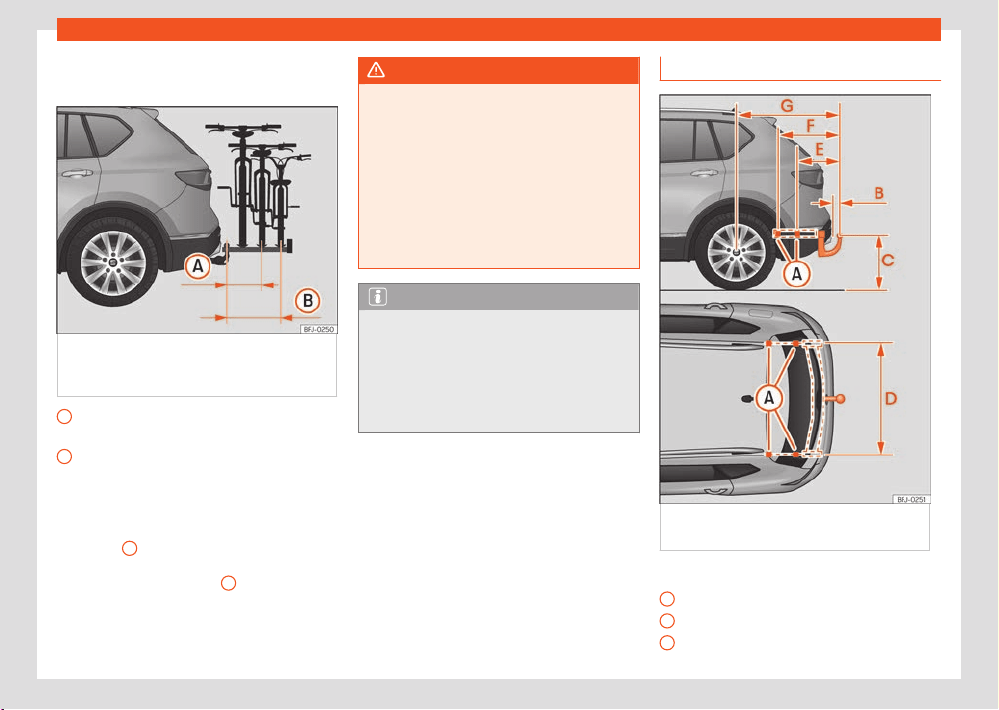
306
Storing objects
A
B
Maximum load overhang of the rear carrier
syst
em
Fig.212 Schematic r
epresentation of the
maximum load overhang of a bicycle rack for two
or three bicycles.
With up to 55 kg load capacity: 500mm
(appr
ox. 19.7in)
With 75 kg load capacity: 700mm (approx.
27.6in)
The maximum overhang shall not exceed
500 mm from the centre of the ball head to
the to the centre of the rail of the last support
›››Fig.212
A
for two-bicycle racks. In the case
of thr
ee-bicycle racks, the overhang must not
exceed 700mm ›››Fig.212
B
.
WARNING
The incorrect use of a rear carrier system in-
st
alled on the tow hook can cause accidents
and injury.
●
Make sure that the carrier system is suita-
ble for your vehicle.
●
Read and observe the installation instruc-
tions of the rear carrier system manufacturer.
●
Never attach a rear carrier system below
the ball head of the trailer hitch. The system
could slip due to the shape of the hitch.
Note
Before setting o, SEAT r
ecommends remov-
ing, to the extent possible, all accessories
from the load attached to the carrier system.
Examples of these accessories are baskets
and panniers, child seats or batteries. This
improves the aerodynamics and centre of
gravity of the rear carrier system.
Retrofitting a t
owing bracket
Fig.213 Limits and att
achment points for
retrofitting a towing bracket.
Distance measurements:
A
Mounting points on the vehicle
B
75 mm (minimum)
C
365 mm
Storing objects
307
Trailer mode
D
1,050 mm
E
353 mm
F
600 mm
G
1,095 mm
SEAT recommends that towing brackets be ret-
r
ofitted at a specialised workshop. For exam-
ple, it may very well be necessary to adjust
the cooling system or mount thermal protection
plates. SEAT recommends visiting a SEAT deal-
ership for this.
If a towing bracket is retrofitted, the distance
specifications should always be kept in mind.
The distance between the centre of the ball
head and the road ›››Fig.213
C
must never
be l
ess than that indicated. This also applies
when the vehicle is fully loaded, including the
technically permissible maximum vertical load
on the coupling device.
WARNING
If the cables are improperly or incorrectly
connect
ed, this may lead to malfunctions in
the entire vehicle electronic system, as well
as to accidents and serious injuries.
●
Never connect the trailer's electric sys-
tem to the electrical connections of the tail
lights or any other unsuitable power sources.
Only use suitable connectors to connect the
trailer.
●
The towing bracket should be retrofitted
only at a specialised workshop.
WARNING
If the towing bracket is badly fitt
ed or unsuit-
able, the trailer may separate from the ve-
hicle while driving. This could cause serious
accidents and fatal injuries.
Note
●
According to regulation EU2021_535 it is
not permitt
ed to install a towing device that
cannot be removed or retracted.
●
Only use towing brackets that have been
approved by SEAT for the model in question.
●
In some versions, the fitting of a conven-
tional towing hook solution is not recommen-
ded. Please consult your Technical Service.

308
Fuel and exhaust gas cleaning
1)
Depending upon country.
Fuel and exhaust gas
cl
eaning
Refuelling
Safety warnings regarding fuel han-
dling
WARNING
Fuel is highly flammabl
e and can cause seri-
ous burns and other injuries.
●
When refuelling, turn o the engine and
turn o the ignition for safety reasons.
●
The fuel system of PHEV models is pressur-
ized to prevent petrol vapours from escaping
into the atmosphere.
●
Do not smoke when filling the fuel tank or
a canister. Naked flames are forbidden in the
vicinity due to the risk of explosion.
●
Observe legislation governing the use,
storage and carrying of a spare fuel canister
in the vehicle.
●
For safety reasons we do not recommend
carrying a spare fuel canister in the vehicle.
In an accident the canister could be dam-
aged and could leak.
●
If, in exceptional circumstances, you have
to carry a spare fuel canister, please observe
the following points:
–
Never fill fuel int
o the spare fuel canister
if it is inside or on top of the vehicle. This
could cause an explosion. Always place
the canister on the ground to fill it.
–
Insert the filling nozzle as far as possible
into the spare fuel canister.
–
If the spare fuel canister is made of
metal, the filling nozzle must be in contact
with the canister during filling. This helps
prevent an electrostatic charge building
up.
–
Never spill fuel in the vehicle or in the
luggage compartment. Fuel vapour is ex-
plosive. Risk of fatal accident!
NOTICE
●
If any fuel is spilt onto the vehicle, it should
be r
emoved immediately. It could otherwise
damage the paintwork.
●
Never run the tank completely dry. The
catalytic converter can be damaged.
●
When filling the fuel tank after having run
it completely dry on a vehicle with a diesel
engine, the ignition must be switched on for
at least 30 seconds before starting the en-
gine. When you then start the engine it may
take longer than normal (up to one minute) to
start firing.
For the sake of the environment
Do not o
verfill the fuel tank, it may cause the
fuel to overflow if it becomes warm.
Note
There is no emergency mechanism for the
manual r
elease of the fuel tank flap. If nec-
essary, request assistance from specialised
personnel.
Note
Diesel vehicles are fitted with a protective
device that prevents the insertion of the
wrong fuel hose
1)
. It is only possible to refuel
with Diesel nozzles.
●
If the pump nozzle is worn, damaged, or if
it is very small, it is possible that it will not
be able to open the protective device. Before
trying to insert the pump nozzle by turning
it, try a dierent pump or request specialist
help.
●
If you fill the tank from a reserve fuel canis-
ter, the protective device will not open. One
way to resolve this is to pour the fuel in very
slowly.
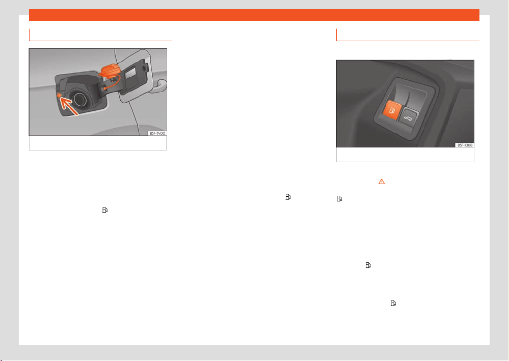
Fuel and exhaust gas cleaning
309
Refuelling
Refuelling
Fig.214 Fuel t
ank flap with tank cap attached.
The fuel tank flap is on the r
ear right of the
vehicle.
●
The tank flap is unlocked when the car is un-
locked using the central locking remote control
›››page86.
Hybrid vehicles: Use the
button on the driver’s
door t
o release the tank flap ›››page309.
●
Open the fuel tank flap by pressing on the
retainer zone.
●
Unscrew the cap by turning it to the left.
●
Place it in the space on the hinge of the open
flap ›››Fig.214.
●
Start refuelling. The tank is full as soon as
the pump
’s automatic nozzle cuts o the fuel
supply. Do not try to put in more fuel after the
nozzle cuts out, as this will fill the expansion
chamber in the fuel tank.
●
Unscrew the cap by turning it to the right as
far as it will go.
●
Close the lid.
The correct fuel grade for your vehicle is given
on a sticker on the inside of the fuel tank
flap. Further notes on fuel can be found at
›››page310.
The capacity of your vehicle's fuel tank is given
in ›››page382.
Hybrid vehicles
Every 6 months it is necessary to run on petrol
until the control lamp switches o
and then
the t
ank must be refilled. This is necessary to
ensure that the system works properly, as well
as the fuel quality required for driving with pet-
rol.
Purging the fuel tank
✓ Valid for: hybrid vehicles.
Fig.215 Driv
er’s door: tank cover release.
Before refuelling the fuel system must be dep-
r
essurised ›››
in Saf
ety warnings regarding
fuel handling on page308. To do this, press the
button on the driver’s door.
An audibl
e sound will be played and a warning
will be displayed on the instrument cluster dis-
play.
After a few seconds the fuel tank flap will un-
lock and remain unlocked for a few minutes. If
you have not refuelled after this time, you must
press the
button again before refuelling.
Av
oid touching the fuel tank flap lock button
›››Fig.214 (arrow). The system will interpret
that you have finished and cannot continue re-
fuelling. Press the
button on the driver’s door
again t
o continue.
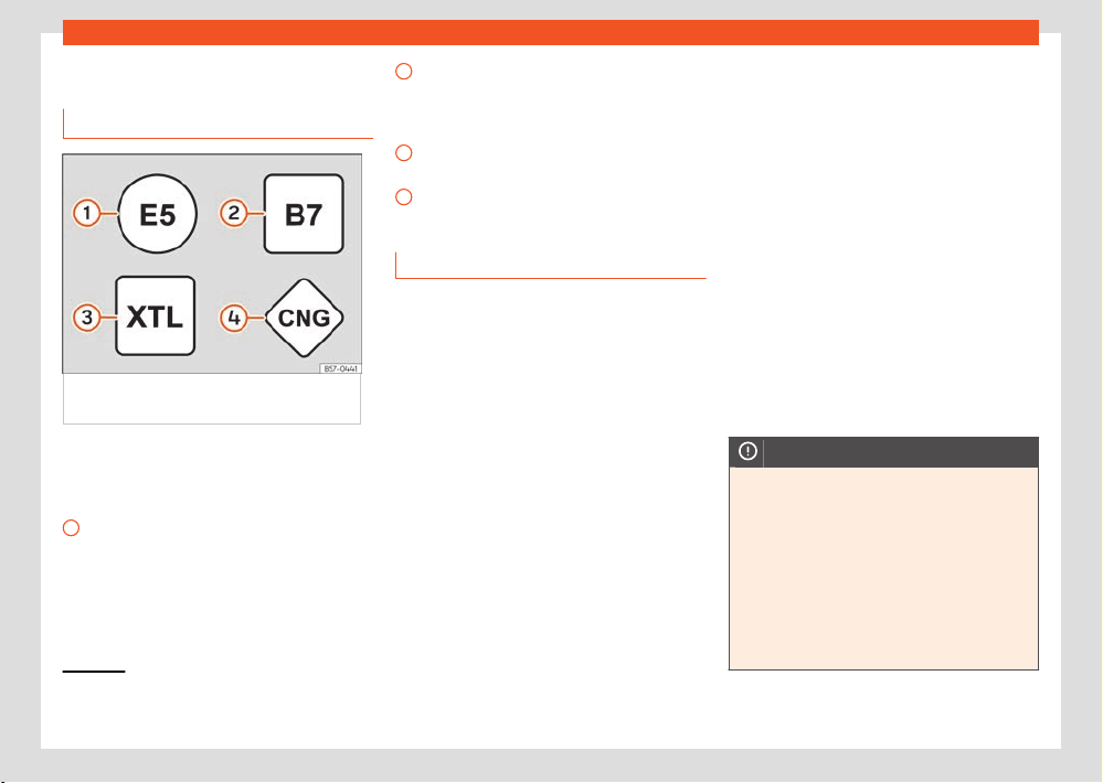
310
Fuel and exhaust gas cleaning
1)
Depending upon country.
2)
Follow the regulations of the country you are driving in.
1
2
3
4
Fuel types
Identification of fuel
s
1)
Fig.216 Identification of fuel
s according to
European Union (EU) Directive 2014/94/
Fuels are identified by dier
ent symbols on
the pump and on your vehicle's tank flap. The
identification serves to prevent confusion when
choosing the fuel.
Petrol with ethanol (“E” stands for Ethanol).
The number indicates the percentage of
ethanol in the petrol. “E5” means, for exam-
ple, an ethanol ratio of 5% max.
Diesel accor
ding to EN590 standard. The
number indicates the maximum percent-
age of Biodiesel in the fuel. “B7” means a
maximum of 7% Biodiesel.
Synthetic diesel according to EN15940
standard.
Natural gas: “CNG” means Compressed
Natural Gas
Type of petrol
The correct grade of petrol is listed inside the
fuel tank flap.
The vehicle is equipped with a catalytic con-
verter and must only be run on unleaded pet-
rol. The petrol must comply with the standard
EN 228 and be sulphur-free. Fuels with a 10%
ethanol ratio can be refuelled (E10)
2)
. The types
of petrol are dierentiated by using the octane
numbers (RON) or via the anti-knock index
(AKI).
Super unleaded petrol 95 octane petrol or
normal 91 octane petrol at least
We recommend refuelling with super 95 octane
petrol (91 AKI). If not available, normal 91 oc-
tane petrol (87 AKI) (with a slight power loss)
may be used.
Super unleaded petrol, 95 octanes at least
You should use super 95 octane petrol (91 AKI)
at least.
If super petrol is not available, if necessary, use
normal 91 octane petrol (87 AKI). In this case
only use moderate engine speeds and a light
throttle. Refuel with super as soon as possible.
Unleaded super plus 98 octane petrol or su-
per 95 octane petrol at least
We recommend refuelling with super plus 98
octane petrol (93 AKI). If not available: super 95
octane petrol (91 AKI) (with a slight power loss).
If super petrol is not available, if necessary, use
normal 91 octane petrol (87 AKI). In this case
only use moderate engine speeds and a light
throttle. Refuel with super as soon as possible.
NOTICE
●
Fuels with a high percentage of ethanol,
e
.g. E30 - E100 button must not be used. The
fuel system would be damaged.
●
A single refuelling with leaded fuel or other
metal additives entails a permanent deterio-
ration of the eectiveness of the catalytic
converter.
●
Only use fuel additives that have been ap-
proved by SEAT. The products that contain
substances to increase the octane rating or
Fuel and exhaust gas cleaning
311
AdBlue®
1)
This motor is only available in some markets.
2)
Depending upon country.
decrease knocking may contain metal addi-
tiv
es that damage the engine and catalytic
converter. This type of products must not be
used.
●
Do not use fuels shown in the pump as
containing metals. LRP (lead replacement
petrol) fuels contain high concentrations of
metal additives. Risk of engine damage!
●
High engine speed and full throttle can
damage the engine when using petrol with
an octane rating lower than the correct
grade for the engine.
Note
●
Fuel with an octane rating higher than the
one r
equired by the engine can be used.
●
In countries in which there is no sulphur-
free fuel, it is also allowed to use low sulphur
content fuel.
Ethanol fuel
✓ Valid for: vehicles with Totalflex engines
You can recognise vehicles with Totalflex en-
gines
1)
by label on the fuel tank lid with the
marking “Petrol/ethanol”.
Vehicles with T
otalflex engine can run with un-
leaded petrol (95 octane / 91 AKI) according
to ANP No. 57 and with fuels with any high per-
centage of ethanol. The vehicle is refuelled in
the same way as petrol refuelling.
Also consider that ›››page310, Type of petrol.
Note
SEAT recommends filling the t
ank exclusively
with petrol every 10,000 km to decrease im-
purities that using E100 ethanol fuel might
have left in the engine.
Diesel
✓ Valid for: vehicles with diesel engines
Please note the information on the inside of the
fuel tank flap.
The diesel can thicken at very low tempera-
tures, thus aecting the start or operation of
the engine. Ask your service station attendant if
their diesel is suitable for winter use.
Water in the fuel filter
2)
If your vehicle has a diesel engine and is equip-
ped with a fuel filter with a water separator,
the instrument panel may display the following
warning:
Water in the fuel filter.
If this is the case, take the vehicle to a special-
ised w
orkshop so that they can drain the fuel
filter.
NOTICE
●
Never use of FAME (biodiesel that does not
meet the EN590 st
andard), petrol, heating
oil, other fuels or thinning agents as they can
cause severely damage the fuel system and
the engine.
●
If the wrong fuel has been filled, do not
start the engine under any circumstances.
Risk of damaging the fuel system and the en-
gine! Seek professional assistance.
AdBlue®
Information about AdBlue®
AdBlue® consumption depends on your per-
sonal driving style, the temperature of the sys-
tem and the outdoor temperature when the ve-
hicle is used.
AdBlue® freezes at temperatures of -11 °C
(+13°F). The system has heating elements that
guarantee its operation even at low tempera-
tures.
When the range is less than 2400 km the
instrument cluster screen displays a message
requesting an AdBlue® refill.
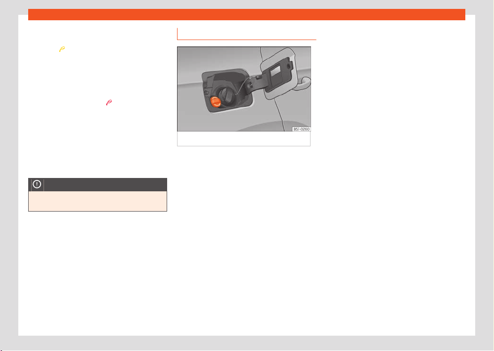
312
Fuel and exhaust gas cleaning
If this message is ignored, the yellow indicator
light will come on once the r
emaining range is
1,000 km
. The indication that in XXX km it
will no l
onger be possible to restart the engine
will appear on the instrument panel display.
If the yellow indicator lamp is ignored, when a
remaining range of 0km is displayed, it will no
longer be possible to restart the engine. The red
warning light will come on
.
AdBlue® is a r
egistered trademark of the Ger-
man Association of the Automotive Industry
(VDA) and is also known as AUS32 or DEF (Die-
sel Exhaust Fluid).
The AdBlue® tank has a capacity of approx.
18 litres.
NOTICE
Overfilling with AdBlue® can cause damage
t
o the tank system.
Fill AdBlue®
Fig.217 AdBlue t
ank cap.
Operations prior to r
efilling
Park the vehicle on a flat surface and turn o
the ignition. If the vehicle is on a slope or on a
curb, the level indicator may not detect the refill
properly.
If an AdBlue® warning message is shown on the
instrument cluster display, fill with at least the
minimum required amount (approx. 5 litres).
Only after adding this amount will the system
detect that AdBlue® has been added and you
will be able to start the engine again. The maxi-
mum amount that can be refilled is 11 litres.
Fill with a refill bottle
Only use AdBlue® that complies with the ISO
22241-1 standard.
●
Only use original containers.
●
Open the tank cover ›››Fig.217.
●
Unscrew the tank cap by turning it in an anti-
cl
ockwise direction.
●
Please observe the manufacturer's instruc-
tions, indicated on the refill bottle.
●
Check the expiry date.
●
Remove the cap of the refill bottle.
●
Insert the neck of the bottle in the tank filler
neck vertically and screw the bottle on by
hand, by turning it in a clockwise direction.
●
Press the refill bottle in the direction of the
filler neck and hold it in this position.
●
Wait until the contents of the refill bottle have
been poured into the AdBlue® tank. Do not
compress or break the bottle!
●
Turn the bottle in a counter-clockwise direc-
tion and gently pull it upwards ›››page313.
●
The AdBlue® tank is full when no more liquid
comes out of the bottle.
●
Screw on the tank cap in a clockwise direc-
tion until it is tightly closed.
●
Close the fuel tank flap.
Operations before driving
●
After refilling the tank, only switch on the igni-
tion.
●
Leave the ignition on for at least 30 seconds
for the system to detect the fluid load.
●
Make sure you wait for at least 30 seconds
before starting the engine!
Fuel and exhaust gas cleaning
313
Engine management and emissions control system
Refilling the dispenser with AdBlue
V
alid for vehicles with selective catalytic reduc-
tion.
●
Open the tank cap.
●
Turn the SCR tank cap anti-clockwise
›››Fig.217.
●
Add AdBlue until the nozzle stops for the first
time.
●
Close the SCR tube by turning it clockwise
until you hear a click.
WARNING
AdBlue® should only be stored in its origi-
nal cont
ainer, which should be tightly closed
and kept in a safe place.
NOTICE
●
When r
efilling, the nozzle grip should be
aligned downward. Otherwise the nozzle will
not connect automatically.
●
Do not try to add any more additive after
the nozzle has stopped for the first time. The
AdBlue tank could overflow and AdBlue could
spill out.
●
Only use AdBlue® that complies with the
ISO 22241-1 standard. Only use original con-
tainers.
●
Never mix AdBlue® with water, fuel or addi-
tives. Any type of damage caused by such a
mixture will not be covered by the warranty.
●
Never pour AdBlue® into the fuel tank! This
coul
d result in engine damage.
●
Do not carry the refill bottle inside the
vehicle. If there is a leak (due to tempera-
ture changes or damage to the bottle), the
AdBlue® may damage the vehicle's interior.
For the sake of the environment
Dispose of the r
efill bottle in an environment-
friendly manner.
Note
Suitable AdBlue® refill bottles can be pur-
chased from SEAT dealerships.
Troubleshooting
AdBlue level® is too low
The indicat
or lamp lights up red. The engine
cannot be restarted!
Stop the vehicle in a suitable, safe and flat area
then top up with the minimum required quantity
of AdBlue® ›››page312.
together with : Fault in the AdBlue
syst
em®
The indicator lamps light up red. The engine
cannot be restarted!
Go to a specialised workshop and get the sys-
tem checked.
The AdBlue reserve® is low
The indicat
or lamp lights up yellow.
To up AdBlue® within the number of kilome-
tres (or miles) that are indicated ›››page312.
SEAT recommends contacting a specialised
workshop.
together with : Fault in the
AdBlue® syst
em.
The control lamps light up yellow. There is
a fault in the AdBlue system or unsuitable
AdBlue® fluid has been used. Go to a special-
ised workshop and get the system checked.
Engine management and
emissions control system
Introduction
WARNING
Due to the high temperatures reached by the
exhaust gas scrubbing system, you should
not park your vehicle near a surface that can
catch fire easily. Fire hazard!
WARNING
Do not apply wax underneath the vehicle
ar
ound the area of the exhaust system: Fire
hazard!
314
Fuel and exhaust gas cleaning
1)
Except 2.0l and 2.5l TSI petrol engines.
Catalytic converter
T
o maintain the useful life of the catalytic
converter
●
Only use unleaded petrol with petrol en-
gines.
●
Never run the fuel tank dry.
●
When changing or adding engine oil, do not
exceed the necessary amount ›››page339,
Checking and topping up the engine oil level.
●
Never tow the vehicle to start it, use jump
leads if necessary ›››page318.
If you should notice misfiring, uneven running or
loss of power when the car is moving, have the
vehicle inspected by a specialised workshop.
In general, the emissions warning lamp
will
light up when any of these sympt
oms occur. If
this happens, any unburnt fuel can enter the ex-
haust system and escape into the atmosphere.
The catalytic converter can also be damaged
by overheating.
NOTICE
Never run the fuel tank completely dry be-
cause an irr
egular fuel supply can cause ig-
nition faults. This allows unburnt fuel to enter
the exhaust system, which could cause over-
heating and damage the catalytic converter.
For the sake of the environment
Even when the emission control system is
w
orking perfectly, there may be a smell of
sulphur from the gases on occasions. This
depends on the sulphur content of the fuel
used. This can quite often be avoided by
changing to another brand of fuel.
Particulate filter
Valid for: vehicles with petrol or diesel particu-
late filters
The particulate filter eliminates most of the
soot from the exhaust gas system. Under nor-
mal driving conditions the filter cleans itself.
If the filter does not clean itself (e.g. if short
journeys are made continuously), it becomes
blocked with soot and the following indication is
displayed to the driver:
Particulate filter: cleaned
while the vehicle is moving. See
Manual.
The particul
ate filter needs cleaning (regenera-
tion).
Regeneration of the petrol and diesel partic-
ulate filter
1)
Requirements for the regeneration journey: the
engine is at operating temperature.
●
Drive at a speed of between 50120 km/h
(31-
75mph). This increases the temperature
and burns the soot in the filter ›››page315.
●
Consider the legal speed limits as well as the
recommended gears.
●
End the regeneration journey once the con-
trol warning lamp has gone out.
If the warning lamp stays on after 30 minutes
of running in regeneration mode, have a speci-
alised workshop repair the fault.
Regeneration of the particulate filter (only
for 2.0l and 2.5l TSI engines)
Requirements for the regeneration journey: the
engine is at operating temperature.
●
Drive at a speed of at least 80 km/h
›››page315.
●
Completely remove your foot from the accel-
erator pedal for a few seconds to let the vehicle
roll with the gear engaged.
●
Consider the legal speed limits as well as the
recommended gears.
●
Repeat this procedure (accelerate and let
roll) until the control lamp turns o.
This procedure involves an autonomous par-
ticulate filter cleaning process and may take
some time.
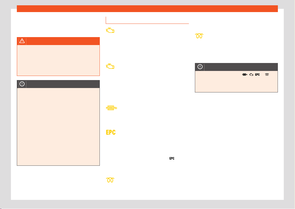
Fuel and exhaust gas cleaning
315
Engine management and emissions control system
If the warning lamp does not t
urn o, go imme-
diately to a specialised workshop to repair the
fault.
WARNING
Always adjust your speed to suit the weather
conditions, r
oads, braking distance and traf-
fic if the particulate filter is in its regeneration
phase. Route recommendations should never
make you disregard each country's specific
trac regulations.
NOTICE
●
When the exhaust system detects that the
par
ticulate filter is close to saturation, the
self-cleaning function of this system recom-
mends optimal driving for this function.
●
Due to the high temperatures caused by
the regeneration of the particulate filter, it is
possible that the radiator fan will activate af-
ter stopping the engine, even it its operating
temperature has not been reached.
●
Noise, smells and high idle speeds can oc-
cur during regeneration.
●
Always use the correct engine oil and the
correct fuel to make sure the useful life of the
particulate filter is not aected. Also avoid
making short trips all the time.
Troubleshooting
Fault in the emissions control system
The indicat
or lamp lights up yellow.
Reduce speed and drive carefully to the near-
est specialised workshop to have the engine
checked.
Combustion failures that could dam-
age the cat
alytic converter
The control lamp flashes yellow.
Reduce speed and drive carefully to the near-
est specialised workshop to have the engine
checked.
Particulate filt
er clogged
The indicator lamp lights up yellow
›››page314..
Petrol engine management fault
The indicat
or lamp lights up yellow.
Have the engine checked as soon as possible
by a specialised workshop.
When the ignition is switched on, the
(Elec-
tr
onic Power Control) lamp lights up and should
go o once the engine has started.
Diesel engine preheating system
The indicat
or lamp lights up yellow.
The engine can be started straight away when
the lamp switches o.
Diesel engine management fault
The contr
ol lamp flashes yellow.
Have the engine checked as soon as possible
by a specialised workshop.
NOTICE
While the indicator lamps , , or
are on, there might be faults in the engine,
fuel consumption may go up and the engine
might l
ose power.
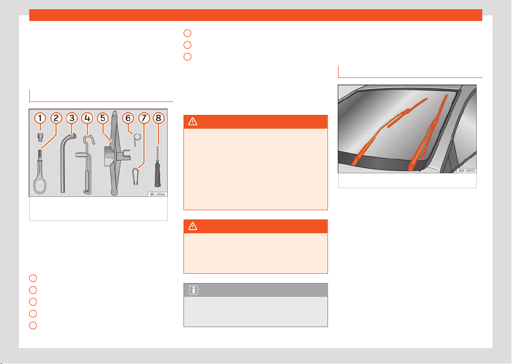
316
Miscellaneous situations
1
2
3
4
5
6
7
8
Miscellaneous situa-
tions
V
ehicle tool kit
On-board toolkit
Fig.218 Underneath the floor panel of the
luggage compartment: on-boar
d tools.
The vehicle tool kit is located under the floor
panel in the luggage compartment. T
o access
the on-board tools ›››page287.
The tool kit includes:
Adapter for the anti-theft bolt
Towing eye, removable
Wheel spanner
Crank handle for jack
Jack
Hook for extracting the central wheel trims
Clip f
or removing the wheel bolt caps
Screwdriver with hexagon socket in the
handle for screwing and unscrewing the
wheel nuts
Some of the items listed are only provided in
certain model versions, or are optional extras.
WARNING
When the vehicle tool kit, tyre mobility set
and spar
e wheel are loose in the interior they
can be violently thrown in case of a sudden
manoeuvre or braking and especially in acci-
dents, causing serious injury.
●
Ensure that the vehicle tool kit, the tyre
mobility set and the spare wheel or tempo-
rary spare wheel are safely secured in the
luggage compartment.
WARNING
Unsuitable or damaged vehicle tools can
cause injury or accidents.
●
Never work with inappropriate or damaged
t
ools.
Note
The jack does not generally require any
maint
enance. If required, it should be
greased using universal type grease.
Changing the windscreen
wiper blades
Wiper service position
Fig.219 Wipers in service position.
Ensure that the wiper blades are not frozen.
With the wiper in service position, it is possible
to the fold the wiper arms ›››Fig.219.
●
Close the bonnet ›››page329.
●
Switch the ignition on and o.
●
Briefly press the wiper lever downwards.
Before driving, always lower the wiper arms. Us-
ing the windscreen wiper lever, the windscreen
wiper arms return to their initial position.
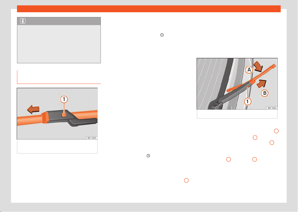
Miscellaneous situations
317
Changing the windscreen wiper blades
Note
●
The wiper arms can be moved into the re-
pl
acement position when the front bonnet is
fully closed.
●
You can also use the service position, for
example, if you want to fix a cover over the
windscreen in the winter to keep it clear of
ice.
Changing the wiper rear wiper
blades
Fig.220 Changing the windscr
een wiper
blades
The windscreen wiper blades are supplied as
st
andard with a layer of graphite. This layer is
responsible for ensuring that the wipe is silent. If
the graphite layer is damaged, the noise of the
water as it is wiped across the windscreen will
be louder.
Check the condition of the wiper blades regu-
l
arly. If the wipers scrape across the glass,
they should be changed if they are damaged,
or cleaned if they are dirty ›››
.
If this does not pr
oduce the desired results,
the setting angle of the windscreen wiper arms
might be incorrect. They should be checked by
a specialised workshop and corrected if neces-
sary.
Damaged windscreen wiper blades should
be replaced immediately. These are available
from qualified workshops.
Raising and lowering windscreen wiper arms
●
Place the windscreen wipers in the service
position ›››page316.
●
Grip the wiper arms only by the blade's fas-
tening point.
Cleaning windscreen wiper blades
●
Raise the wiper arms.
●
Use a soft cloth to remove dust and dirt from
the windscreen wiper blades.
●
If the blades are very dirty, a sponge or damp
cloth may be used ›››
.
Changing the windscr
een wiper blades
●
Lift and unfold the wiper arms.
●
Press and hold release button ›››Fig.220
1
and pull gently on the wiper blade in the direc-
tion of the arr
ow.
●
Fit a new wiper blade of the same length
and design on to the wiper arm and hook it into
place.
●
Rest the wiper arms back onto the wind-
screen.
Changing the rear window wiper blade
Fig.221 Changing the r
ear wiper blade
●
Separate the wiper arm from the rear window.
●
Rotate the blade lightly ›››Fig.22
1 (arrow
A
).
●
Hold down the release button
1
while gently
pulling the bl
ade in the direction of arrow
B
.
●
Insert a new blade of the same l
ength and
type in the rear wiper arm in the opposite direc-
tion to the arrow
B
until button
1
hooks into
pl
ace.
●
Fold the wiper arm and rest it on the window.
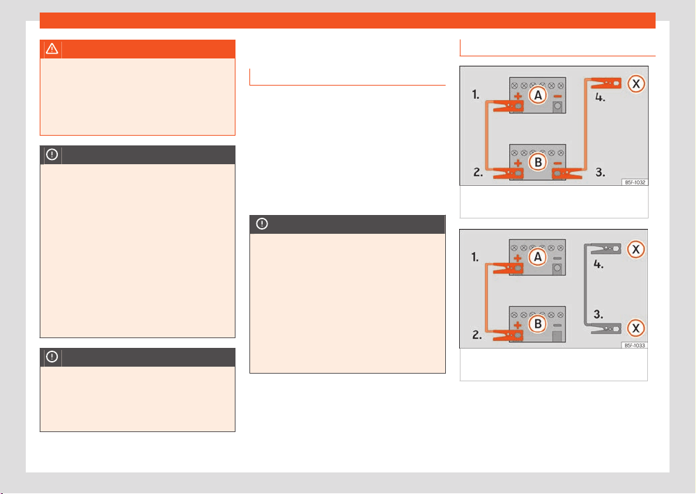
318
Miscellaneous situations
WARNING
Worn or dirty windscreen wiper blades re-
duce visibilit
y and increase the risk of acci-
dent and serious injury.
●
Always replace damaged or worn wind-
screen wiper blades or blades that no longer
clean the windscreen properly.
NOTICE
●
Damaged or dirty windscreen wipers could
scr
atch the glass.
●
If products containing solvents, rough
sponges or sharp objects are used to clean
the blades, the graphite layer will be dam-
aged.
●
Never use fuel, nail varnish remover, paint
thinner or similar products to clean the win-
dows.
●
In icy conditions, always check that the
wiper blades are not frozen to the glass be-
fore using the wipers. In cold weather, it may
help to leave the vehicle parked with the wip-
ers in service position ›››page316.
NOTICE
●
To prevent damage to the bonnet and the
wiper arms, only leave them in the service
position.
●
Before driving, always lower the wiper
arms.
Jump start
Intr
oduction
If the engine fails to start because of a dis-
charged 12-volt battery, the battery can be
connected to the battery of another vehicle to
start the engine.
Jump leads complying with the DIN 72553
standard are needed for starting (see cable
manufacturer's instructions). The wire cross
section must be at least 25 mm
2
for petrol en-
gines and at least 35 mm
2
for diesel engines.
NOTICE
To avoid considerable damage to the vehicle
electrical system, note the following care-
fully:
●
If the jump leads are connected incor-
rectly, a short circuit may occur.
●
Use only jump leads with fully insulated
clamps.
●
Do not allow the vehicles to come into con-
tact with each other, otherwise current may
start to flow as soon as the positive poles are
connected.
Jump start: description
Fig.222 Diagr
am of connections for vehicles
without Start Stop system
Fig.223 Diagr
am of connections for vehicles
with Start Stop system
The discharged battery must be properly con-
nect
ed to the on-board network.
Make sure the battery clamps have sucient
metal-to-metal contact with the battery termi-
nals.

Miscellaneous situations
319
Jump start
1.
2.
3.
4.
5.
6.
7.
8.
9.
10.
11.
Jump lead terminal connections
The jump l
eads should only be connected in
the order 1 > 2 > 3 > 4 ›››Fig.223.
Switch o the ignition of both vehicles
›››
.
Connect one end of the r
ed jump lead to
the positive
+
terminal of the vehicle with
the flat batt
ery
A
.
Connect the other end of the r
ed jump lead
to the positive terminal
+
in the vehicle
pr
oviding assistance
B
.
V
ehicles without a Start-Stop system: con-
nect one end of the black jump lead to the
negative terminal
–
of the vehicle provid-
ing the curr
ent
B
›››Fig.222.
V
ehicles with a Start-stop system: connect
one end of the black jump lead
X
to a
suit
able ground terminal, to a solid piece of
metal in the engine block, or to the engine
block itself ›››Fig.223.
Connect the other end of the black jump
lead
X
to a solid metal component bolted
t
o the engine block or to the engine block
itself of the vehicle with the flat battery. Do
not connect it to a point near the battery A.
Position the leads in such a way that they
cannot come into contact with any moving
parts in the engine compartment.
Starting
Start the engine of the vehicle with the
boosting battery and let it run at idling
speed.
Start the engine of the vehicle with the flat
battery and wait for 2 or 3 minutes until the
engine is running.
Removing the jump leads
Before you remove the jump leads, switch
o the dipped beam headlights if they are
switched on.
Turn on the heater blower and heated rear
window in the vehicle with the flat battery.
This helps minimise voltage peaks which
are generated when the leads are discon-
nected.
When the engine is running, disconnect the
leads in reverse order to the details given
above.
If the engine fails to start after about 10sec-
onds, switch o the starter and try again after
about 1 minute.
WARNING
●
Please note the safety warnings refer-
ring t
o working in the engine compartment
›››page329.
●
The battery providing assistance must
have the same voltage as the flat battery
(12V) and approximately the same capacity
(see imprint on battery). Failure to comply
could result in an explosion.
●
Never use jump leads when one of the bat-
teries is frozen. Danger of explosion! Even
after the battery has thawed, battery acid
could leak and cause chemical burns. If a
battery freezes, it should be replaced.
●
Keep sparks, flames and lighted cigarettes
away from batteries, danger of explosion.
Failure to comply could result in an explo-
sion.
●
Observe the instructions provided by the
manufacturer of the jump leads.
●
Do not connect the negative cable from
the other vehicle directly to the negative ter-
minal of the flat battery. The gas emitted
from the battery could be ignited by sparks.
Danger of explosion.
●
Never attach the negative cable to fuel
system components or the brake lines in the
other vehicle.
●
The non-insulated parts of the battery
clamps must not be allowed to touch. The
jump lead attached to the positive battery
terminal must not touch metal parts of the
vehicle, this can cause a short circuit.
320
Miscellaneous situations
●
Position the leads in such a way that they
cannot come int
o contact with any moving
parts in the engine compartment.
●
Do not lean on the batteries. This could re-
sult in chemical burns.
●
Take into account the instruction manual of
the jump lead manufacturer and the instruc-
tion manual of the other vehicle.
NOTICE
Immediately go to a specialist workshop and
hav
e the 12 volt battery checked.
Towing the vehicle
Introduction
It takes practice to tow a vehicle, especially
when using a tow cable. Both drivers should be
well informed of the special features of towing.
Inexperienced drivers should refrain from tow-
ing.
During towing, make sure at all times that no
inadmissible traction forces or jolts are gener-
ated. On roads without a firm surface there is
always the danger of overloading the attach-
ment parts.
Take into account the legal provisions regarding
tow starting and towing.
Tow start
T
ow starting means starting a vehicle's engine
while another puts it in motion by pulling it.
The vehicle can be towed with a tow bar or
cable
Towing
Towing means a vehicle pulling another vehicle
that is not in a condition to run.
The vehicle can be towed with a tow bar or
cable.
●
The maximum permitted speed is 50km/h
(30 mph).
●
The maximum permitted distance is 50km
(30 miles).
Tow cable and tow bar
It is safer for the vehicle to be towed using a tow
bar, avoiding damage to the vehicle. The tow
cable should only be used if a tow bar is not
available.
A tow rope should be slightly elastic to avoid
damage to both vehicles. It is advisable to use
a tow rope made of synthetic fibre or similarly
elastic material.
Tow with a tow truck
If a breakdown lorry is used, vehicles with au-
tomatic transmission are only allowed to be
towed with the front wheels suspended.
Towing vehicles with four-wheel drive
(4Drive)
Four-wheel drive vehicles (4Drive) can be
towed using a tow bar or tow rope. If the vehicle
is towed with the front or rear axle suspended,
the engine must be switched o, otherwise the
transmission may be damaged.
WARNING
During the towing of a vehicle, the driving
behaviour and br
aking capacity change con-
siderably.
WARNING
Never allow the vehicle to be towed if it has
no po
wer.
●
When towing, never remove the key from
the ignition or disconnect the ignition with
the ignition and start button. Otherwise, the
electronic lock of the steering column could
suddenly get blocked and it would be impos-
sible to steer the vehicle. This could cause an
accident, serious injury and loss of control of
the vehicle.
●
If the vehicle runs out of power during tow-
ing, stop the process immediately and seek
the assistance of specialised personnel.
Miscellaneous situations
321
Towing the vehicle
NOTICE
Towing the vehicle with a tow cable or a tow
bar can cause damage t
o the vehicle.
●
If the vehicle is towed with a tow cable or
tow bar, special care must be taken.
●
If possible, have the vehicle transported on
a tow truck.
NOTICE
If the vehicle is pushed by hand, the tail light
units, the side spoil
ers of the rear window
and large sheet metal surfaces may be dam-
aged. In addition, the rear spoiler could be
detached.
●
If the vehicle is pushed by hand, the tail
light units, the side spoilers of the rear win-
dow, large sheet metal surfaces or the rear
spoiler.
NOTICE
Removing and attaching the cover and the
towing eye may cause damage to the vehi-
cle, for example, on the paintwork.
●
To avoid damaging the vehicle, remove and
replace the cover and the towing eye care-
fully.
NOTICE
Using a towing eye that is not suitable for the
v
ehicle can damage it.
●
When towing, always use the vehicle’s tow-
ing eye, which forms part of the on-board
tools, or an appropriate eye for towing.
Instructions for tow-starting and
towing
During towing, the change of direction can be
signalled on the towed vehicle even when the
hazard warning lights are on. To do so, at the
same time, the turn signal lever must be oper-
ated with ignition switched on. During this time
the hazard warning lights remain disconnected.
When the turn signal lever is returned to the
rest position, the hazard warning lights will be
automatically reactivated.
Cases where tow starting and towing the ve-
hicle are not permitted
Do not allow the vehicle to be towed in the
following situations:
●
The vehicle’s gearbox is damaged or has no
lubricant.
●
The 12-volt battery is discharged. In vehicles
with the “K
eyless Access” locking and ignition
system the steering remains locked and the
parking brake cannot be deactivated and the
steering column lock cannot be released if they
are connected.
●
If a distance above 50 km needs to be travel-
l
ed.
●
There is no guarantee that the wheels will
turn smoothly or that the steering will work after
an accident.
If the vehicle cannot be towed on its wheels for
any of the reasons mentioned above, request
assistance from specialised personnel and, if
necessary, have the vehicle transported with-
out the wheels touching the ground.
Tow start
Steps to be taken prior to tow starting
Vehicles with an automatic gearbox: Due to
technical reasons, tow starting the vehicle is not
allowed. Attempt to start the engine using the
starting aid ›››page318.
Vehicles with a manual gearbox: In general, it
is not recommended to tow start the vehicle. If
the engine does not start, try the starting aid
first ›››page318. Please note that, in the case
of petrol engines, the maximum permitted dis-
tance for tow starting is 50m.
●
Secure the tow cable or tow bar using only
the attachment points provided for this pur-
pose.
●
Switch on the ignition and the hazard warning
lights.
●
Engage 2nd or 3rd gear while the vehicle is
st
opped.
●
Press the clutch and hold it down.
322
Miscellaneous situations
●
When both vehicles are in motion, release the
clut
ch pedal.
●
As soon as the engine starts, depress the
clutch and disengage the gear to avoid collid-
ing with the towing vehicle.
NOTICE
When tow-starting, unburnt fuel could enter
the cat
alytic converter and damage it.
Towing
Previous steps
●
Secure the tow cable or tow bar using only
the att
achment points provided for this purpose
›››
. Depending on the equipment, these
points may be a t
owing device or a towing eye.
●
Make sure the tow cable is not twisted. Other-
wise the towing eye could unscrew during tow-
ing.
●
Switch on the ignition and the hazard warning
lights of both vehicles. If necessary, take into
account other dierent provisions that may ex-
ist in this regard.
●
Take into account the instructions on towing
provided in the instruction manual of the other
vehicle.
Towing vehicle (front)
●
Do not actually start driving until the cable is
tight.
●
Accelerate with particular care.
●
Avoid sudden braking and manoeuvres.
V
ehicles with a manual gearbox:
●
When starting to drive, use the clutch very
gently.
Towed vehicle (behind)
●
Make sure the ignition is switched on so that
the steering wheel does not lock and so that, if
necessary, you can use the turn signals and the
windscreen wiper.
●
The brake servo and power steering only
work when the engine is running. Otherwise,
you will have to depress the brake pedal con-
siderably harder and more force will be needed
to turn the steering wheel.
●
Release the electronic parking brake.
●
Make sure the tow cable is always taut.
●
Disengage the gear or place the gear selec-
tor in the Nposition.
WARNING
Never attach the tow rope or tow bar to axle
or running gear components. They coul
d be
damaged, resulting in an accident and seri-
ous injury.
●
Seek specialist assistance and, if applica-
ble, have the vehicle transported on a tow
truck.
NOTICE
The vehicle can only be towed if the state of
char
ge of the 12-volt battery is sucient to
disengage the electronic parking brake and
the steering column lock. If the vehicle has
no power supply or there is an electric sys-
tem fault, the engine must be jump-started
to release the electronic parking brake and
deactivate the electronic lock of the steering
column.
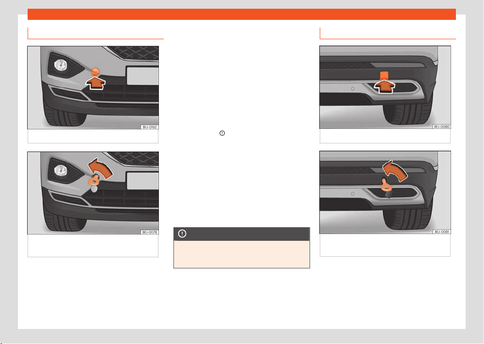
Miscellaneous situations
323
Towing the vehicle
Front towline anchorage
Fig.224 Fr
ont bumper on right: remove the lid.
Fig.225 Right side of the fr
ont bumper: towline
anchorage screwed in.
The housing of the removable towline anchor-
age is on the right side of the fr
ont bumper un-
derneath a cover ›››Fig.224.
The towing eye should always be kept in the
vehicle.
Bear in mind the instructions for towing
›››page32
1.
Fitting the towline anchorage
●
Remove the towing eye from the vehicle tool
kit in the luggage compartment ›››page316.
●
Remove the cover by pressing down on its
base and leave it hanging from the vehicle
›››Fig.224.
●
Screw the towing eye in the housing by
turning it to the maximum anticlockwise
›››Fig.225 , ›››
. Use a suitable object that
can compl
etely and securely tighten the towing
eye in its housing.
●
After towing, unscrew the towing eye clock-
wise with a suitable object.
●
Replace the cover and push it in until it clicks
into place.
●
Clean the towing eye if necessary and then
store it in the luggage compartment along with
the other vehicle tools.
NOTICE
The towing eye must always be completely
and firmly tight
ened. Otherwise, it could
jump out of the housing during towing.
Rear towline anchorage
Fig.226 R
ear bumper on right: remove the lid.
Fig.227 Right side of the r
ear bumper: towline
anchorage screwed in.
The housing of the screw towing eye is on
the right side of the r
ear bumper behind a lid
›››Fig.226.
324
Miscellaneous situations
Vehicles fitt
ed as standard with a towing
bracket do not have any housing for the screw
towing eye behind the lid. In this case, the tow
hitch needs to be extracted or installed and
used for towing ›››page297 , ›››
.
Bear in mind the instructions f
or towing
›››page321.
Assemble the rear towing eye (cars without
a factory-equipped towing bracket)
●
Remove the towing eye from the vehicle tool
kit in the luggage compartment ›››page316.
●
Press the lower side of the lid ›››Fig.226 t
o
unclip it.
●
Remove the lid and let it hang from the vehi-
cle.
●
Screw the towing eye in the housing by
turning it to the maximum anticlockwise
›››Fig.227 , ›››
. Use a suitable object that
can compl
etely and securely tighten the towing
eye in its housing.
●
After towing, unscrew the towing eye clock-
wise with a suitable object.
●
Replace the cover and press until the tab
snaps into the bumper.
●
Clean the towing eye if necessary and then
store it in the luggage compartment along with
the other vehicle tools.
NOTICE
●
The towing eye must always be com-
pl
etely and firmly tightened. Otherwise, it
could be released while towing and tow-
starting.
●
If the vehicle is factory-equipped with a
towing bracket, it is only allowed to tow with
a tow bar if this has been specially designed
to be installed with a tow hitch. If an unsuita-
ble tow bar is used, both the tow hitch and
the vehicle may be damaged. Instead, a tow
rope should be used.
Fuses
Introduction
In general, a fuse can be assigned to various
electrical components. Likewise, an electrical
component can be protected by several fuses.
Only replace fuses when the cause of the
problem has been solved. If a newly inserted
fuse blows after a short time, you must have
the electrical system checked by a specialised
workshop as soon as possible.
WARNING
The high voltages in the electrical system
can giv
e serious electrical shocks, causing
burns and even death!
●
Never touch the electrical wiring of the ig-
nition system.
●
Take care not to cause short circuits in the
electrical system.
WARNING
Using unsuitable fuses, repairing fuses or
bridging a curr
ent circuit without fuses can
cause a fire and serious injury.
●
Never use a fuse with a higher value. Only
replace fuses with a fuse of the same amper-
age (same colour and markings) and size.
●
Never replace a fuse by a metal strip, sta-
ple or similar.
NOTICE
●
To prevent damage to the vehicle’s electri-
cal system, before replacing a fuse always
turn o the ignition, the lights and all electri-
cal elements.
●
Protect the fuse boxes when open to pre-
vent the entry of dust or humidity as they can
damage the electrical system.
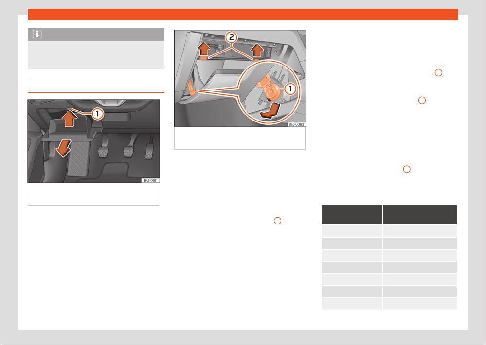
Miscellaneous situations
325
Fuses
Note
In the vehicle, there are more fuses than
those indicat
ed in this chapter. These should
only be replaced by a specialist workshop.
Fuses inside the vehicle
Fig.228 On the dashboar
d on the driver side:
lid of the fuse box.
Fig.229 Right
-hand drive vehicles: fuse box
cover under the passenger side dash panel.
Vehicles with the steering wheel on the left:
open the fuse bo
x cover under the dash
panel
●
Open the storage compartment on the driver
side ›››Fig.228.
●
In this case, empty the storage compartment.
●
Press the locking tab›››Fig.228
1
upwards,
in the dir
ection of the arrow, and at the same
time open the storage compartment even more
and remove it until the fuse box can be ac-
cessed.
●
To install the storage compartment, insert it in
the openings of the dashboard and press it until
you hear it click on both sides. Close it.
Right-hand drive vehicles: open the fuse box
behind the glove compartment
●
Open the glove compartment and, if neces-
sary, empty it.
●
Move the locking element ›››Fig.229
1
into the support hole facing downwards and
r
emove it to one side.
●
Press the end pivots›››Fig.229
2
upwards,
in the dir
ection of the arrows, and at the same
time open the glove compartment even more.
●
To mount the glove compartment, place it in
the correct position. Insert the braking element
into the hole of the base and move it upwards
until you hear it click. Carefully press the glove
compartment forwards, against the resistance
of the end pivots ›››Fig.229
2
..
Identifying fuses bel
ow the dashboard by
colours
Colour
Current intensity in
amps
Orange 5
Brown 7.5
Red 10
Blue 15
Yellow 20
White or transparent 25
Green 30
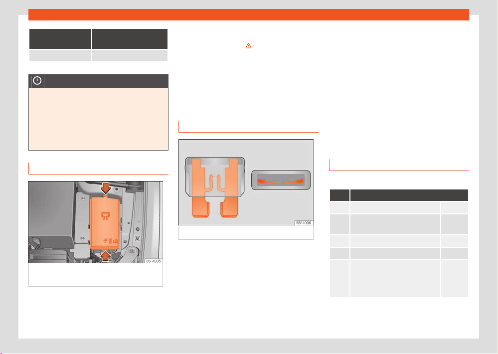
326
Miscellaneous situations
Colour
Current intensity in
amps
Orange 40
NOTICE
●
Always carefully remove the fuse box cov-
ers and r
efit them correctly to avoid prob-
lems with your vehicle.
●
Protect the fuse boxes when open to avoid
the entry of dust or humidity. Dirt and humid-
ity inside fuse boxes can cause damage to
the electrical system.
Fuses in the engine compartment
Fig.230 In the engine compartment: lid of the
fuse bo
x.
To open the engine compartment fuse box
●
Raise the bonnet ›››
on page329.
●
Press the locking tabs to unlock the fuse box
co
ver ›››Fig.230.
●
Then lift the cover out.
●
To fit the cover, place it on the fuse box. Push
the locking tabs down until they click audibly
into place.
Replace a blown fuse
Fig.231 Image of a bl
own fuse.
Preparations
●
Switch o the ignition, lights and all el
ectrical
equipment.
●
Open the corresponding fuse box
›››page325, ›››page326.
Recognise a blown fuse
A bl
own fuse can be recognised if the metal
strip is melted ›››Fig.231.
●
Point a lamp at the fuse to see if it has blown.
To replace a fuse
●
Remove the fuse.
●
Replace the blown fuse by one with an iden-
tical amperage rating (same colour and mark-
ings) and identical size.
●
Replace the cover again or close the fuse box
lid.
Fuse placement
Fuses in the vehicle interior
No. Consumers/Amps
1 Adblue (SCR) 30
4
DWA warning horn, on-board
comput
er
7.5
5 Gateway 7.5
6 Automatic gearbox lever 7.5
7
Air conditioning and heating
control panel, back window
heating, auxiliary heating, rear
heating
10

Miscellaneous situations
327
Fuses
No. Consumers/Amps
8
Diagnosis, electronic parking
br
ake switch, light switch, re-
verse light, interior lighting, driv-
ing mode, lit-up door sill, light/
humidity/rain sensor, curve
lighting control unit
7.5
9 Steering column control unit 7.5
10 Radio display 7.5
11 On-board computer control unit 40
12 Infotainment radio 30
13 Driver seat belt pre-tensioner 25
14 Air conditioner fan 40
15 Steering column release 10
16
GSM signal reception and sta-
bilisation, mobile phone inter-
face, USB connections control
unit
7.5
17
Dashboard, OCU navigation in-
terface
7.5
18
Surroundings camera and rear
camera control unit
7.5
19 Kessy 7.5
20 SCT 1.5 L engine vacuum pump 7.5/15
21 4x4 Haldex Control Unit 15
22 Trailer 15
23 Electric sunroof 20
No. Consumers/Amps
24 On-board computer 40
25 Left doors 30
26 Heated seats 30
27 Interior light 30
28 Trailer 25
30
PHEV. Switching o the high
voltage system for rescue tasks.
Identified by a yellow label.
10
31 Electrical lid control unit 30
32
Control unit for park distance
control, front camera and radar
10
33 Airbag 7.5
34
Reverse switch, climate sensor,
electrochromic mirror, electro-
mechanical brake
7.5
35 Diagnosis connector 7.5
38 Trailer 25
39 Right doors 30
40/1 12V socket 20
41
Passenger seat belt pre-ten-
sioner
25
42 Central locking 40
43 Digital sound control unit 30
44 Trailer 15
No. Consumers/Amps
45 Electric driver's seat 15
47 Rear window wiper 15
48 SoundAktor 7.5
49 Starter motor 7.5
51 Rear AC 25
52 Driving mode 15
53 Heated rear window 30
Fuse arrangement in engine compartment
No. Consumers/Amps
1 ABS/ESP control unit 25
2 ABS/ESP control unit 40/60
3
Engine control unit (petrol/die-
sel)
15/30
4
Engine sensors, electric fans,
pressure regulator, flow rate
meter, spark plug relay (diesel),
PTC relays
7.5/10
5 Engine sensors 10
6 Brake light sensor 7.5
7 Engine power supply 7.5/10
8 Lambda probe 10/15
9 Engine 10/20
10 Fuel pump control unit 15/20
328
Miscellaneous situations
No. Consumers/Amps
11 PTC 40
12 PTC 40
13
Automatic transmission oil cool-
ing pump
30
15 Horn 15
16
Ignition coil relay (2.0 petrol),
inv
erter, on-board control unit
10/20
17
Engine control unit, ABS/ESP
control unit, primary relay
7.5
18 Terminal 30 (positive reference) 7.5
19 Front windscreen washer 30
20 eBKV 40
21 Automatic gearbox control unit 15
22 Engine control unit 7.5
23 Starter motor 30
24 PTC 40
36 Left headlight 15
37 Parking heating 20
38 Right headlight 15
Note
●
In the vehicle, there are more fuses than
those indicat
ed in this chapter. These should
only be changed by a specialised workshop.
●
Positions not containing a fuse do not ap-
pear in the following tables.
●
Some of the equipment listed in the tables
below pertain only to certain versions of the
model or are optional extras.
●
Please note that the above lists, while cor-
rect at the time of printing, are subject to
change.
Changing bulbs
Change a bulb
LED technology lights
Full-LED headlights handle all light functions
(daylight, side light, turn signal, dipped beam
and route light) with light emitting diodes (LEDs)
as a light source.
Full-LED headlights are designed to last the
lifetime of the car and light bulbs cannot be
replaced. In case of headlight failure, go to an
authorised workshop to have it replaced.
The fog lights, tail lights, number plate light, side
turn signals and additional brake light are all
LED bulbs. With this in mind, they should be re-
placed by a technical service.
Checking and r
efilling levels
329
Engine compartment
Checking and r
efilling
levels
Engine compartment
Working in the engine compartment
The engine compartment of the vehicle is a
dangerous area. You should only perform works
in the engine compartment if you have good
knowledge of the necessary operations and the
general safety measures, and if you have ade-
quate tools, means and operating fluids. Works
performed inadequately, could lead to serious
injuries ›››
. In this case, seek a specialised
w
orkshop to perform all the works. SEAT rec-
ommends visiting a SEAT dealership for this.
Before performing any work in the engine com-
partment, always park the vehicle on level and
firm ground, taking all necessary safety pre-
cautions.
WARNING
Any accidental movement of the vehicle dur-
ing maint
enance work could cause serious
injuries.
●
Never perform works underneath the vehi-
cle without having first immobilised it to pre-
vent it from moving. When working under the
vehicle with the wheels on the ground, the
vehicle must be on a level surface and the
wheels must be locked.
●
If work must be performed underneath the
v
ehicle, take the extra precaution of support-
ing it safely using suitable assembly support.
The jack is not suitable for this purpose and
may not withstand, which could lead to seri-
ous injuries.
●
The Start-Stop system must be switched
o manually.
WARNING
The engine compartment of any vehicle is a
danger
ous area in which serious injuries can
be caused!
●
When performing any type of work, always
ensure you are extremely cautious, and bear
in mind the general safety measures. Never
put yourself at risk.
●
Never perform works in the engine com-
partment if you do not have solid knowledge
of the necessary operations. If you are un-
sure of what needs to be done, seek a speci-
alised workshop to perform the works. Works
performed inadequately, could lead to seri-
ous injuries.
●
Never open or close the bonnet if you
see steam or coolant escaping from the en-
gine compartment. Steam or hot coolant can
cause severe burns. Always wait until you
stop hearing or seeing the steam or coolant
discharging from the engine compartment.
●
Before opening the bonnet, always wait for
the engine to cool down.
●
Touching hot engine or exhaust system
components coul
d result in skin burns.
●
Turn o the ignition and keep the vehicle
key in a safe place at a safe distance from
the vehicle to prevent the ignition from being
turned on and the combustion engine started
by mistake.
●
Always keep children away from the en-
gine compartment and never leave them un-
supervised.
●
When the motor is hot, its cooling system is
pressurised. Do not open the expansion tank
cap, hot coolant may splash out and cause
severe burns and other injuries.
–
Turn the coolant expansion tank cap
slowly and very carefully anticlockwise
while pressing it down slightly.
–
Always protect your face, hands and
arms from the hot coolant and steam with
a large thick cloth.
●
When refilling operating fluids, ensure they
do not spill onto the components of the en-
gine or onto the exhaust system. These liq-
uids could cause a fire.
330
Checking and r
efilling levels
WARNING
The electrical system is under high voltage
and can cause el
ectrical shocks, burns, seri-
ous injuries and even death!
●
Never short circuit the electrical system.
The 12-volt battery could explode.
●
To reduce the risk of electric shock and se-
rious injury, never touch the electrical wires
of the ignition system while the engine is run-
ning or when starting.
WARNING
There are rotating parts in the engine com-
par
tment which could cause serious injury.
●
Never insert your hand in the radiator fan
or around that area. All the rotor blades can
cause serious injuries. The fan activates de-
pending on the temperature and can switch
on automatically, even if the ignition is o.
●
If any work has to be done during engine
start-up or when it is running, take into ac-
count that the rotating parts (e.g. the poly-
V belt, alternator and the radiator fan) and
the high-voltage ignition system pose a fatal
hazard. Always act with extreme care.
–
Ensure that no part of your body, or any
jewellery or tie, loose clothing, loose long
hair can become trapped in the rotating
parts. Before performing works in the en-
gine compartment, remove any jewellery
or tie you may be wearing, tie up your hair
if it is long and gather any loose clothing.
–
Do not press the accelerator pedal while
not paying att
ention. Always do so with ex-
treme care. The vehicle could move, even if
the electronic parking brake is activated.
●
Do not leave objects in the engine com-
partment, e.g. rags or tools.
WARNING
The operating fluids and some mat
erials of
the engine compartment are highly flamma-
ble and could cause a fire and serious inju-
ries!
●
Never smoke in the vicinity of the engine
compartment.
●
Never perform works close to unprotected
flames or sparks.
●
When you must perform works on the on-
board 12 volt electrical system, bear in mind
the following:
–
Always disconnect the 12 volt battery.
Ensure the vehicle is unlocked when dis-
connecting the 12-volt battery, otherwise
the anti-theft alarm will trigger.
–
Never perform works in the vicinity of
heating elements, water boilers or unpro-
tected flames.
●
Always have a fire extinguisher close-by,
ensuring it is operational and had been
checked.
NOTICE
When r
efilling or changing the operating flu-
ids, ensure you pour the correct fluids into
their corresponding filler caps. Using the
wrong operating fluids can lead to serious
malfunctions and motor damage.
For the sake of the environment
Operating fluids that o
verflow from the ve-
hicle contaminate the environment. There-
fore, check underneath the vehicle on a reg-
ular basis. If there are marks left by operat-
ing fluids on the ground, consult a special-
ised workshop and request the vehicle be
checked. If any operating fluid leaks out, dis-
pose of it in the correct manner.
Preparing the vehicle for work in the
engine compartment
Before performing works in the engine com-
partment, always perform the following opera-
tions in the order indicated ›››
:
1. Place the vehicle on level and firm gr
ound,
taking all necessary safety precautions.
2. Press the brake pedal and keep it pressed
until the ignition is switched o.
3. Apply the electronic parking brake.
4. Manual transmission: place the gear lever
in neutral.
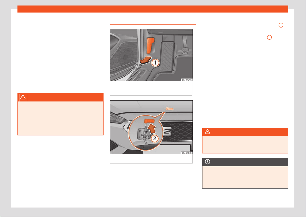
Checking and r
efilling levels
331
Engine compartment
Automatic transmission: mo
ve the selector
lever to position P.
5. Switch the ignition o ›››page150.
6. Remove the vehicle key from the vehicle
and store it outside to avoid inadvertently
starting the engine.
7. Wait for the engine to cool down su-
ciently.
8. Always keep other people away from the
engine compartment.
9. Immobilize the vehicle so that it cannot
move.
WARNING
For your own safety, do not ignore this impor-
t
ant check list, otherwise this could cause
accidents and serious injuries.
●
Always follow the indications on the check
list and always bear in mind the general
safety measures.
Opening and closing the bonnet
Fig.232 R
elease lever in the driver's footwell
area.
Fig.233 L
ever under the bonnet.
Opening the bonnet
The bonnet is r
eleased from inside the vehicle.
Before opening the bonnet, make sure that the
windscreen wiper arms are in place against the
windscreen.
●
Open the door and pull the lever that is un-
derneath the instrument panel ›››Fig.232
1
.
●
To lift the bonnet, press the release catch un-
der the bonnet up
wards ›››Fig.233
2
. The
arr
ester hook under the bonnet is released.
●
The bonnet can be opened. Release the bon-
net stay and secure it in the fixture designed for
this in the bonnet.
Closing the bonnet
●
Slightly lift the bonnet.
●
Release the bonnet stay and replace it in its
support.
●
At a height of approximately 20 cm let it fall
so it locks.
If the bonnet does not close, do not press
downwards. Open it again and let it fall as
mentioned above.
WARNING
Make sure that the bonnet is properly closed.
If it opens when driving, it can cause an acci-
dent.
NOTICE
To avoid damage to the bonnet and to the
windscr
een wiper arms, only open it when
the windscreen wipers are in place against
the windscreen.
332
Checking and r
efilling levels
Fluids and consumables
Intr
oduction
All fluids and consumables, such as engine
coolant or vehicle batteries, are subject to con-
tinuous development. For this reason, whenever
a fluid or consumable needs to be replaced,
please contact a specialist workshop.
SEAT dealers always promptly receive informa-
tion about any modifications.
WARNING
If unsuitable fluids and consumables are
used or used improperly, accidents, injuries,
burns and severe poisoning can occur.
●
Only store operating fluids in their original
containers, tightly closed.
●
Never store operating fluids in empty food
cans, bottles or other empty containers, as
they could be ingested by somebody.
●
Keep all fluids and consumables out of
reach of children.
●
Always read and observe the information
and warnings given on containers of operat-
ing fluids.
●
When using products that emit harmful va-
pours, always work outdoors or in a well-ven-
tilated area.
NOTICE
Use only appropriate operating fluids. Ne
ver
confuse operating fluids. This could result in
serious malfunctions and motor damage!
For the sake of the environment
Leakages of operating fluids can cont
ami-
nate the environment. If any operating fluid
leaks, collect it in an appropriate container
and dispose of it properly and in an environ-
mentally friendly manner.
Cooling system
Introduction
Only carry out work on the motor cooling sys-
tem yourself if you are familiar with the neces-
sary operations and the generally applicable
safety measures, and if you have the appro-
priate tools, equipment and operating fluids.
Works performed inadequately could lead to
serious injuries . In this case, seek a specialised
workshop to perform all the works. SEAT rec-
ommends visiting a SEAT dealership for this.
WARNING
Engine coolant is toxic!
●
Only store coolant in its original container,
tightly cl
osed and in a safe place.
●
Never store motor coolant in empty food
cans, bottles or other empty containers, as it
could be ingested by another person.
●
Always keep motor coolant out of reach of
children.
●
Ensure that the coolant fluid additive per-
centage is correct, taking into account the
lowest ambient temperature expected in the
location where the vehicle is to be used.
●
When the outside temperature is very low,
the coolant could freeze and the vehicle
could be immobilised. In this case, the heat-
ing would not work either and inadequately
dressed passengers could die of cold.
For the sake of the environment
Coolants and additives can contaminate the
envir
onment. If any operating fluid leaks out,
collect it and dispose of it properly and in an
environmentally friendly manner.
Coolant specifications
The factory fitted motor cooling system is filled
with a mixture of specially treated water and at
least 40% coolant additive G12evo (TL-VW 774
L).
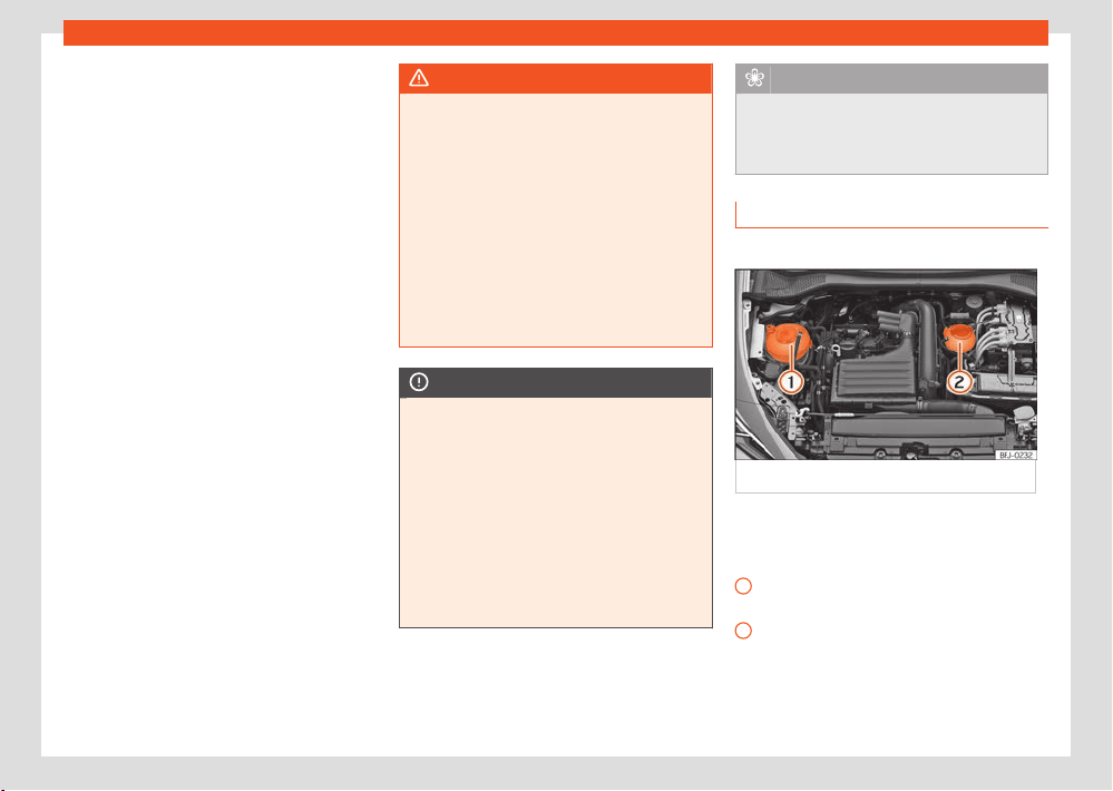
Checking and r
efilling levels
333
Cooling system
1
2
Get information from a specialist workshop
about which cool
ant is suitable for your vehicle.
SEAT recommends visiting a SEAT dealership
for this.
To protect the engine cooling system, the ad-
ditive percentage should always be at least
40%. If more antifreeze protection is required
for climatic reasons, the additive proportion
can be increased. However, it should only be
increased up to a maximum of 55 %, otherwise
the antifreeze protection would be reduced and
the cooling eect would be impaired.
The G12evo (TL-VW 774 L) can be recognised
by its lilac colouring. This mixture of water
and additive not only provides antifreeze pro-
tection down to -25°C (-13°F), but also pro-
tects the light alloy parts of the cooling system
against corrosion, prevents limescale build-up
and considerably raises the boiling point of the
coolant.
When topping up the coolant, a mixture of dis-
tilled water and at least 40% of the appropri-
ate coolant additive should be used for opti-
mum corrosion protection ›››page334.
WARNING
If the vehicle’s cooling system does not have
sucient antifr
eeze protection, the engine
could fail and this could result in serious in-
jury.
●
Ensure that the coolant fluid additive per-
centage is correct, taking into account the
lowest ambient temperature expected in the
location where the vehicle is to be used.
●
When the outside temperature is very low,
the coolant could freeze and the vehicle
could be immobilised. In this case, the heat-
ing would not work either and inadequately
dressed passengers could die of cold.
NOTICE
Never mix the original additives for the
G12e
vo coolant (TL-VW 774 L) with motor
coolant fluid not authorised by SEAT.
●
If the fluid in the expansion tank does not
have a pink colour (resulting from mixing the
lilac additive with distilled water), but is, for
example, brown, the suitable coolant may
have been mixed with another unsuitable
one. The coolant must be changed as soon
as possible if this is the case! Otherwise se-
rious malfunctions or damage to the engine
and the cooling system could occur!
For the sake of the environment
Motor coolant and its additives can pollute
the envir
onment. If any operating fluid leaks
out, collect it and dispose of it properly and
in an environmentally friendly manner.
Coolant tank
✓ Valid for: hybrid vehicles.
Fig.234 Engine compartment: Cool
ant tanks
Hybrid vehicles have 2 independent coolant ex-
pansion t
anks.
›››Fig.234
Coolant expansion tank for the combustion
engine.
Coolant expansion tank for the high-volt-
age system. Visually check the coolant
level of the high-voltage system Do not
open it! It is sealed.
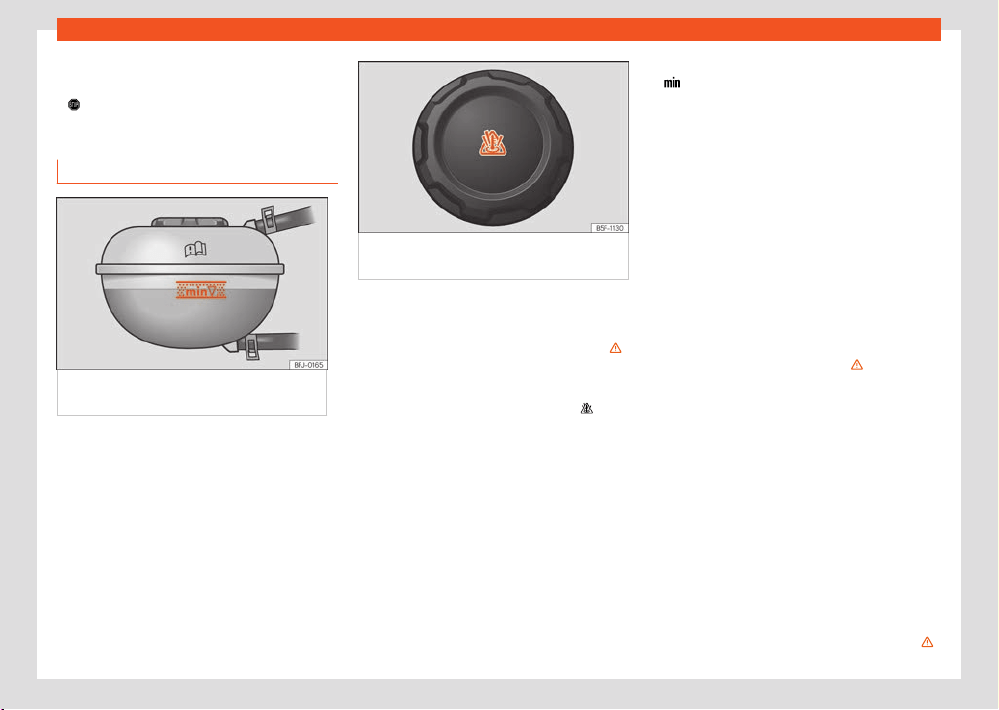
334
Checking and r
efilling levels
If the coolant level in the cooling syst
em of the
high-voltage system is too low:
●
Do not t
op up coolant!
●
Contact a specialised workshop immediately.
Check and refill the coolant
Fig.235 In the fr
ont compartment: marking on
coolant expansion tank.
Fig.236 Fr
ont compartment: coolant
expansion tank cap.
Previous steps
●
Park the vehicle on a firm, flat surf
ace.
●
Wait until the engine has fully cooled ›››
.
●
Open the front bonnet.
●
The motor coolant expansion tank can be
r
ecognised by the symbol on the cap
›››Fig.236
Check the l
evel
When the vehicle is delivered (new vehicles),
the coolant may be above the marked area.
This is normal. It is not necessary to suck the
coolant out.
●
When the engine is cold, check the coolant
level using the side marking on the expansion
tank ›››Fig.235. The coolant level should be
between the marks.
●
If the level is below the minimum level mark
(
) on the tank, top up with coolant. When the
mot
or is warm, the coolant level may be slightly
above the upper mark.
Topping up the fluid
When the motor coolant level is too low, the
coolant warning light comes on. In this case,
immediately seek assistance from specialist
personnel.
If the coolant level is too low and there is no
workshop nearby, note the following:
●
Always protect your face, hands and arms
from hot coolant or steam by placing a suitable
cloth over the cap of the motor coolant expan-
sion tank.
●
Carefully unscrew the cap ›››
.
●
Only top up with fr
esh coolant according to
SEAT specifications ›››page332.
●
Only top up with coolant if there is still some
coolant left in the expansion tank; otherwise the
motor could be damaged! If you do not see any
coolant in the expansion tank, do not continue
driving and seek specialist assistance.
●
If there is still some coolant left in the expan-
sion tank, top up with coolant up to the tank’s
upper mark and check the level the next day.
If the level drops again, go to a workshop and
request a check of the cooling system.
●
The coolant level must be between the marks
on the expansion tank ›››Fig.235. Never ex-
ceed the top edge of the marked area ›››
.
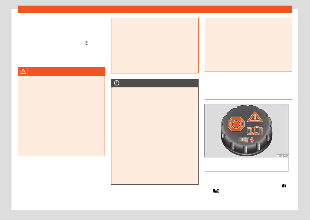
Checking and r
efilling levels
335
Brake fluid
●
Screw the cap on tightly.
●
If engine coolant with the recommended
specifications is not av
ailable in an emergency,
do not use any other coolant additive! In this
case, top up with distilled water ›››
only.
Ne
xt, ensure that the recommended additive is
topped up as soon as possible in the correct
proportion ›››page332.
WARNING
Steam and hot motor coolant can cause se-
v
ere burns.
●
Never open the front bonnet if you see or
hear steam or coolant escaping from the
front compartment. Always wait until you can
no longer see or hear steam or coolant es-
caping. Touching hot parts can result in skin
burns.
●
Before opening the front bonnet, please
note the following:
–
Apply the electronic parking brake.
–
Always keep children away from the front
compartment and never leave them unat-
tended.
●
When the motor is hot, its cooling system is
pressurised. Do not open the expansion tank
cap, hot coolant may splash out and cause
severe burns and other injuries.
–
Turn the cap slowly and very care-
fully anticlockwise while pressing it down
slightly.
–
Always protect your face, hands and
arms from the hot coolant and steam with
a large thick cloth.
NOTICE
Only use distilled water! Other types of wa-
t
er contain chemical substances that could
cause significant corrosion damage. If you
have added non-distilled water, have all of
the motor cooling system fluid changed im-
mediately by a specialist workshop.
●
When topping up the, do not fill over the
upper edge of the marked area ›››Fig.235.
Otherwise, when the temperature rises the
excess fluid will be expelled from the motor
cooling system and could cause damage.
●
If the system leaks a lot of coolant, only
refill once the motor has cooled down com-
pletely. If there is a significant loss of cool-
ant, there may be leaks in the cooling sys-
tem. Immediately go to a specialist workshop
to have the system checked. This could result
in motor damage.
●
Do not add coolant if the expansion tank
is completely empty! Air may have got into
the cooling system. Do not continue driving
and seek assistance from specialist person-
nel. This could result in motor damage.
●
When changing the operating fluids, make
sure that you pour the correct fluids into the
correct filler necks. Using the wrong operat-
ing fluids can lead to serious malfunctions
and motor damage.
Brake fluid
Check and refill the brake fluid
Fig.237 Engine compartment: br
ake fluid
reservoir cap.
Checking the brake fluid l
evel
The brake fluid level must be between the
and markings.
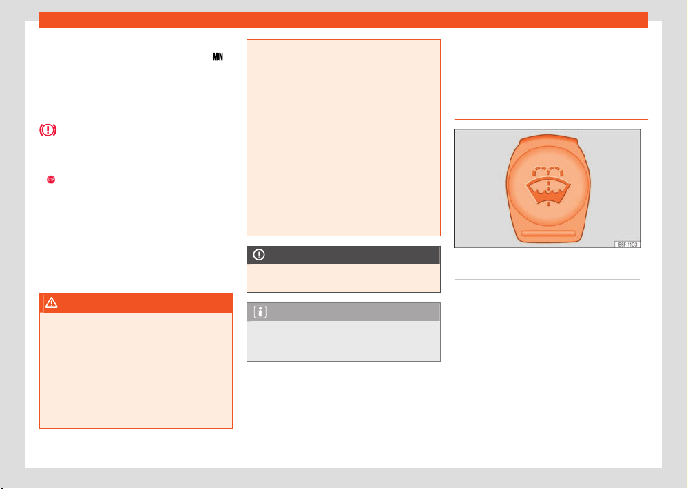
336
Checking and r
efilling levels
However, if the brake fluid l
evel goes down no-
ticeably in a short time, or drops below the
mark, there may be a leak in the brake system.
Seek specialist assist
ance. A warning light on
the instrument panel display monitors the brake
fluid level.
Brake fluid l
evel
The control lamp lights up red.
Brake fluid level is too low.
●
Stop driving!
●
Check the brake fluid l
evel.
●
If the brake fluid level is too low, seek special-
ist assistance.
Changing brake fluid
We recommend that you have the brake fluid
changed by a Technical Service.
WARNING
If the brake fluid l
evel is low or unsuitable/old
brake fluid is used, the brake system may fail
or braking power may be reduced.
●
Check the brake system and the brake fluid
level regularly!
●
When the brake fluid is used and brakes
are subjected to extreme braking forces,
bubbles of vapour form in the brake system.
These bubbles can significantly reduce brak-
ing power, notably increasing braking dis-
tance, and could result in the total failure of
the brake system.
●
Be sure to always use the correct brake
fluid. Only use brake fluid that expressly
meets the VW 501 14 standard.
●
You can buy VW 501 14 standard brake
fluid in a SEAT dealership or a SEAT O-
cial Service. If none is available, use only
high-quality brake fluid that meets DIN ISO
4925 CLASS 4 standards, or USA Standards
FMVSS 116 DOT4.
●
The replacement brake fluid must be new.
●
Brake fluid should be stored in the closed
original container in a safe place out of
reach of children. Risk of poisoning!
NOTICE
Brake fluid shoul
d not come into contact with
the vehicle paintwork, as it is abrasive.
Note
Brake fluid is an environmental pollutant.
Collect any spilt service fluids and allow a
professional to dispose of them.
Windscreen washer reser-
v
oir
Checking the level of the window
washer tank and refilling it
Fig.238 In the engine compartment: blue cap
of the windscr
een washer tank.
Check the water level in the windscreen washer
r
eservoir regularly and top up as required.
The window washer tank contains liquid deter-
gent for the windscreen and rear window.
There is a sieve in the filler neck of the washer
fluid tank. When filling the tank, this sieve re-
tains large dirt particles so that they do not
reach the nozzles. Do not remove the sieve ex-
cept for cleaning. If the sieve is damaged or
not fitted, these dirt particles could enter the
system during filling and clog the windscreen
washer nozzles.
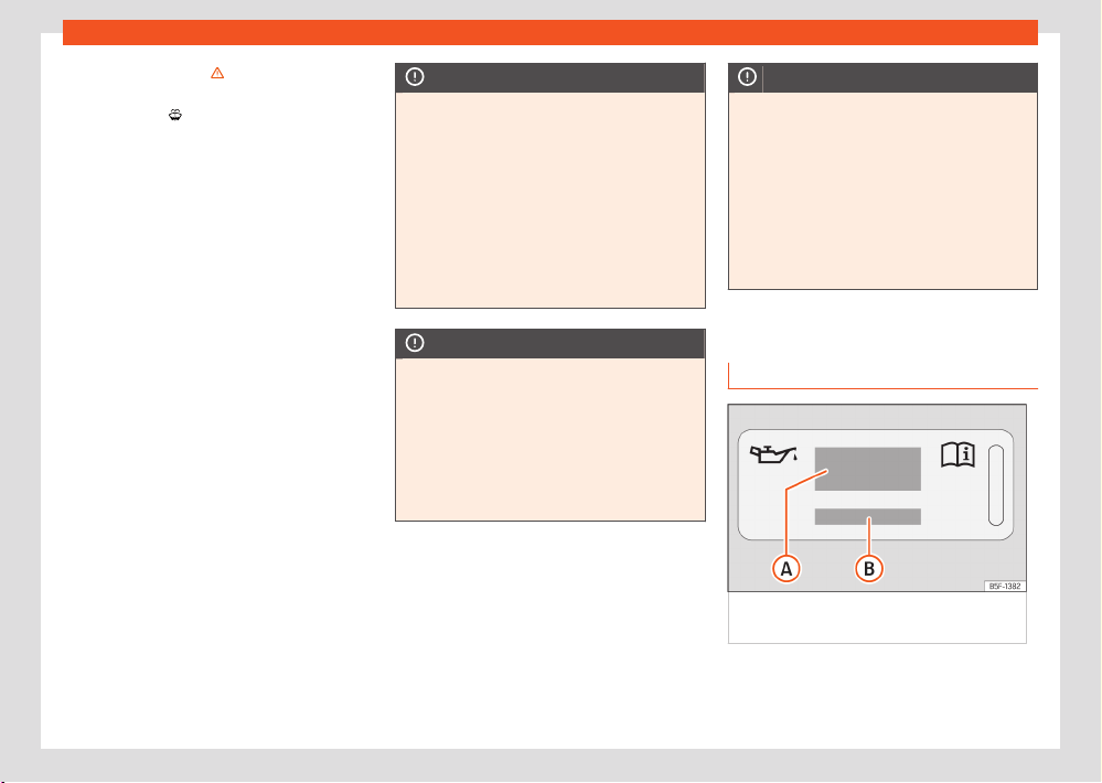
Checking and r
efilling levels
337
Engine oil
●
Raise the bonnet ›››
on page329.
●
The windscreen washer reservoir is marked
with the symbol on the cap.
●
Check if there is enough fluid in the t
ank.
Plain water is not enough to clean the wind-
screen and headlights. We recommend that
you always add a product to the windscreen
washer fluid.
Recommended windscreen wipers
●
For the hottest seasons we recommend sum-
mer G 052 184 A1 for clear glass. Proportions of
the mixture in the washer fluid tank: 1:100 (1 part
concentrate per 100 parts water).
●
All year round, G 052 164 A2 for clear glass.
Approximate proportion of the winter mixture,
up to -18°C (0°F): 1:2 (1 part concentrate per
2 parts water); otherwise, a 1:4 proportion of
mixture in the washer fluid tank.
The capacity of the windscreen washer tank is
approximately 3 litres.
NOTICE
If the water from the windscreen washer
does not cont
ain enough anti-freeze, it may
freeze on the windscreen and rear window,
reducing forward and rear visibility.
●
In winter, ensure the windscreen washer
contains enough anti-freeze.
●
In cold conditions, you should not use the
windscreen wiper system unless you have
warmed the windscreen with the ventilation
system. The antifreeze could freeze on the
windscreen and reduce visibility.
NOTICE
Never mix an unsuitable antifreeze or other
simil
ar additives with the windscreen washer
water. A greasy layer may be formed on the
windscreen which will impair visibility.
●
Use clean water with a window cleaner
recommended by SEAT.
●
If necessary, add a suitable antifreeze to
the water in the reservoir.
NOTICE
●
Do not mix cleaning products recommen-
ded by SEAT with other pr
oducts. This could
lead to flocculation and may block the wind-
screen washer jets.
●
When topping up service fluids, make ab-
solutely certain that you fill the fluids into
the correct reservoirs. Using the wrong fluids
could cause serious malfunctions.
●
Lack of window washer fluid causes the
view through the windscreen to be obscured.
Engine oil
General notes
Fig.239 In the engine compartment: engine
oil l
abel
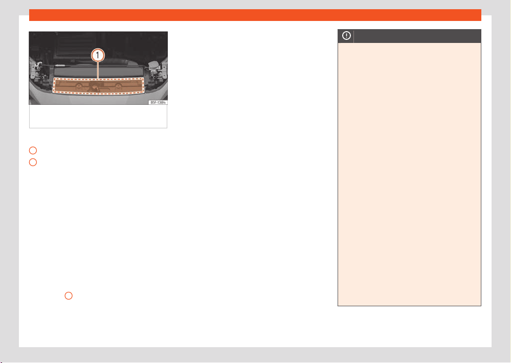
338
Checking and r
efilling levels
A
B
–
–
Fig.240 In the engine compartment: ar
ea
where the engine oil label is located
Key to the ›››Fig.239:
Information about the engine oil standard.
Inf
ormation about engine oil viscosity.
The engine comes with a special, multi-grade
oil that can be used all year round.
Because the use of high-quality oil is essential
for the correct operation of the engine and its
long useful life, when topping up or changing
oil, use only those oils that comply with VW
standards.
For vehicles with an engine oil label
If the engine oil has to be topped up, use one
of the oils shown on the label ›››Fig.239.
The label with the prescribed standard is loca-
ted at the front of the engine compartment
›››Fig.240
1
. If you use the recommended
engine oil, you can t
op up the oil as often as
necessary.
For vehicles without an engine oil label
Contact a specialised workshop or SEAT of-
ficial service for information about the corre-
sponding standard.
If the engine oil level is too low
If the recommended engine oil is not availa-
ble, in the event of an emergency you can
change the oil once with a maximum of 0.5 l of
the next oil until the next oil change:
Petrol engines: VW50400, ACEAC3 or
API SN standard.
Diesel engines: VW50700, ACEAC3 or
API CJ-4, viscosity 0W-30.
SEAT recommends changing the oil at a speci-
alised workshop. SEAT recommends an Ocial
SEAT Service.
SEAT recommends the use of engine oils ap-
proved according to the appropriate VW stand-
ard. Use of engine oils that do not meet these
quality requirements can cause engine dam-
age.
SEAT recommends the use of Original SEAT
Spare Part engine oils.
Engine oil additives
No type of additive should be mixed with the
engine oil. The deterioration caused by these
additives is not covered by the warranty.
NOTICE
Take the following into account if you have
r
efilled with an engine oil dierent to those
specified in the aforementioned standards,
or by your SEAT technical service centre:
●
There is no way of completely avoiding the
danger of causing damage to the engine and
particulate filter.
●
You can continue driving with the vehicle if
the refill was no more than 0.5l of engine
oil. Go to a specialised workshop as soon
as possible and request an oil change. Oth-
erwise, there is a danger of engine damage.
●
If you have topped up more than 0.5l of
engine oil, drive with the engine at low load
levels and within the medium RPM range as a
maximum. Do not drive at more than 80 km/h
and do not travel more than 300 km (approx-
imately). Go to a specialised workshop as
soon as possible and request an oil change.
Otherwise, there is a danger of engine dam-
age.
●
You are responsible for the risk of possible
damage to the vehicle (engine, exhaust sys-
tem). If in doubt, do not start the engine and
request assistance from the technical serv-
ice centre.
●
Do not start the engine if you have topped
up with a fluid other than engine oil. Request
assistance from the technical service centre.
Danger of engine damage!
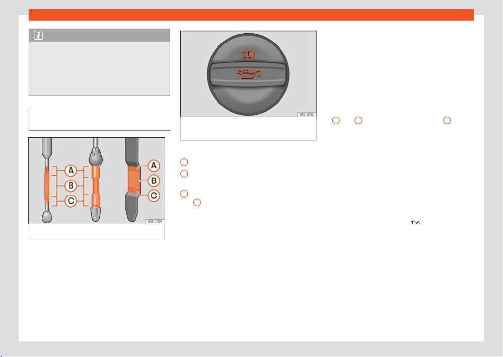
Checking and r
efilling levels
339
Engine oil
A
B
C
Note
Before a long trip, we recommend finding an
engine oil that conf
orms to the correspond-
ing VW specifications and recommend keep-
ing it in the vehicle. This way, the correct en-
gine oil will always be available for a top-up
if needed.
Checking and topping up the engine
oil level
Fig.241 Engine oil dipstick
.
Fig.242 Oil fill
er cap cover in the engine
compartment.
Key to the ›››Fig.2
41:
Do not top up oil in any case.
You can add oil but keep the level in that
zone.
The oil level is too low. Add oil up to zone
B
.
Before opening the bonnet, read and observe
the w
arnings ›››page329, Working in the en-
gine compartment.
Check the oil level
The engine oil dipstick indicates the level of the
oil.
●
Park the vehicle in a horizontal position.
●
Briefly run the engine at idle speed until the
operating temperature is reached and then
stop.
●
Wait for about two minutes.
●
Locate the oil level dipstick. It can be recog-
niz
ed by its coloured upper end.
●
Pull out the dipstick. Wipe the dipstick with a
clean cloth and insert it again, pushing it in as
far as it will go.
●
Then pull it out again and check the oil level
›››Fig.241. Top up with engine oil if necessary.
The oil should leave a mark between the areas
A
and
C
. It must never exceed zone
A
.
Depending on ho
w you drive and the conditions
in which the vehicle is used, oil consumption
can be up to 0.5 l/1000 km. Oil consumption
is likely to be higher for the first 5,000 km. For
this reason the engine oil level must be checked
at regular intervals, preferably when filling the
tank and before a journey.
Topping up engine oil
●
Locate the engine oil filler cap. It can be
recognized by the symbol
on the cover
›››Fig.2
42.
●
Unscrew cap from the oil filler mouth
›››Fig.242.
●
Carefully add oil in small quantities (no more
than 0.5 l).
●
To avoid adding too much oil, whenever you
add a certain amount, wait about 2 minutes
and recheck the oil level ›››page339.
●
If necessary, add some more oil.
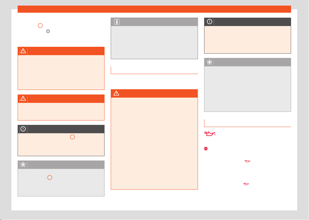
340
Checking and r
efilling levels
●
When the oil level reaches at least zone
›››Fig.2
41
B
, carefully screw on the engine
oil fill
er cap ›››
.
Engine oil specification ›››page337.
WARNING
Any work carried out in the engine compart-
ment or on the engine must be carried out
cautiously.
●
When working in the engine compart-
ment, al
ways observe the safety warnings
›››page329.
WARNING
Oil is highly inflammabl
e! Ensure that no oil
comes into contact with hot engine compo-
nents when topping up.
NOTICE
If the oil level is above zone
A
, do not start
the engine
. This could result in damage to
the engine and catalytic converter. Contact
a Technical Service.
For the sake of the environment
Under no circumstances should the oil level
be abo
ve zone
A
. Otherwise oil can be
drawn in through the crankcase breather and
leak into the atmosphere via the exhaust sys-
tem.
Note
Before a long trip, we recommend finding an
engine oil that conf
orms to the correspond-
ing VW specifications and recommend keep-
ing it in the vehicle. This way, the correct en-
gine oil will always be available for a top-up
if needed.
Engine oil change
We recommend that you have the engine oil
changed by a Technical Service.
WARNING
Only change the engine oil yourself if you
hav
e the specialist knowledge required!
●
Before opening the bonnet, read and ob-
serve the warnings ›››page329.
●
Wait for the engine to cool down. Hot oil
may cause burn injuries.
●
Wear eye protection to avoid injuries, such
as acid burns, caused by splashes of oil.
●
When removing the oil drain plug with your
fingers, keep your arm horizontal to help pre-
vent oil from running down your arm.
●
Wash your skin thoroughly if it comes into
contact with engine oil.
●
Engine oil is poisonous! Used oil must be
stored in a safe place out of the reach of
children.
NOTICE
No additives should be used with engine
oil. This coul
d result in engine damage. Any
damage caused by the use of such additives
would not be covered by the factory war-
ranty.
For the sake of the environment
●
We recommend that you change the en-
gine oil and the filt
er at a technical service
centre.
●
Never pour oil down drains or into the
ground.
●
Use a suitable container when draining the
used oil. It must be large enough to hold all
the engine oil.
Troubleshooting
Engine oil pressure too low
The indicat
or lamp lights up red.
Do not carry on driving! S
witch o the en-
gine. Check the engine oil level.
●
If this warning lamp
starts to flash, and
is accompanied by thr
ee audible warnings,
switch o the engine and check the oil level. If
necessary, add more oil ›››page339.
●
If the warning lamp
flashes although the
oil l
evel is correct, stop driving. Do not even
run the engine at idle speed! Seek professional
assistance.
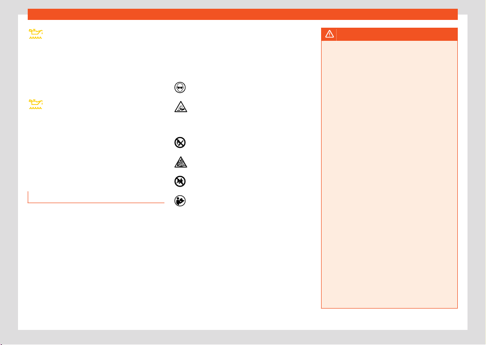
Checking and r
efilling levels
341
12-volt battery
Engine oil level too low
The indicat
or lamp lights up yellow.
●
Check the engine oil level as soon as possible
›››page339.
●
Change the oil as soon as you have the op-
portunity to do so.
Fault in the oil level sensor
The contr
ol lamp flashes yellow.
●
Have the check done by a specialised work-
shop.
●
Until then it is advisable to check the oil level
every time you refuel.
12-volt battery
Introduction
The 12 volt battery is located in the engine
compartment or in the luggage compartment
(PHEV hybrid vehicles). The 12 volt battery is
checked and, if necessary, replaced as part of
maintenance work.
All work on batteries requires specialist knowl-
edge. Please refer to a SEAT Ocial Service
or a workshop specialising in batteries: risk of
burns or exploding battery!
The battery must not be opened! Never try to
change the fluid level of the battery. Otherwise
explosive gas is released from the battery that
could cause an explosion.
Battery warning indications
Wear protective goggles.
Battery acid is extremely corrosive. Wear
protective gloves and eye protection.
Rinse any splashes of electrolyte with
plenty of water.
Fires, sparks, open flames and smoking
are prohibited.
The battery should only be charged in a
well-ventilated zone. Risk of explosion!
Keep children away from acid and the
battery.
Always follow the instruction manual.
If the vehicle is not used for long periods
The v
ehicle has a system for monitoring
the current consumption when the engine
is left unused for extended periods of time
›››page345. Some functions, such as the in-
terior lights, or the remote door opening, may
be temporarily disabled to prevent the battery
from running flat. These functions will come
back on as soon as the ignition is switched on
and the engine started.
WARNING
Working on the 12-volt battery and electri-
cal syst
em can cause severe burns, fire and
electric shock. Always read and observe the
following warnings and safety precautions
before working on the battery:
●
Before working on the 12-volt battery,
switch o the ignition and all electrical con-
sumers and disconnect the negative cable
from this battery.
●
Always keep children away from the 12-volt
battery electrolyte and the battery itself.
●
Always wear eye protection and protective
gloves.
●
The battery electrolyte is very corrosive It
can cause skin burns and blindness. When
handling the 12-volt battery, protect your
hands, arms and face in particular from acid
splashes
●
Do not smoke while working and never
work in the vicinity of naked flames or sparks.
●
Avoid sparks caused by electrostatic dis-
charges, just like when handling electric ca-
bles and devices.
●
Never short the battery terminals.
●
Never use damaged 12-volt batteries. They
could explode. If the 12-volt battery is dam-
aged, replace it immediately.
●
Never use a frozen 12 volt battery. When
the battery is discharged, it may freeze at
temperatures close to 0°C (+32°F). If the 12-
volt battery is frozen, replace it immediately.
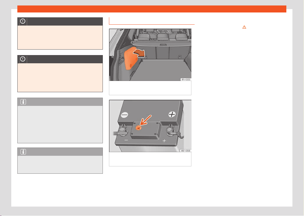
342
Checking and r
efilling levels
Yellow or colourless:
Black:
NOTICE
Do not expose the 12-volt battery to direct
sunlight f
or a prolonged period of time.
●
Ultraviolet rays can damage the battery
casing.
NOTICE
If the vehicle is not to be used for a long pe-
riod of time
, protect the 12-volt battery from
frost.
●
The battery may freeze and, as a result,
suer irreparable damage.
Note
After starting the engine with a deeply dis-
char
ged or newly replaced 12-volt battery,
or after a jump start, some system settings
(time, date, personalised comfort settings
and programs) may be incorrectly set or de-
leted. Check and correct these settings once
the battery is suciently charged.
Note
During the winter, the starting power may
be r
educed, and if necessary, the battery
should be charged.
Check the electrolyte level
Fig.243 Hybrid v
ehicles (PHEV): location of
the battery in the luggage compartment
Fig.244 Sight gl
ass on the top of the 12 volt
battery (schematic representation).
Access to the 12 volt battery
The 12-v
olt battery is located in the engine
compartment (conventional vehicles) or under
the luggage compartment floor (PHEV hybrid
vehicles).
Valid for conventional vehicles:
●
Raise the bonnet ›››
in W
orking in the
engine compartment on page329.
●
Lift the cover that protects the front of the
battery.
Valid for hybrid vehicles (PHEV):
●
Open the luggage compartment.
●
The 12V battery is located inside the left side
compartment ›››Fig.243.
●
Remove the side trim cover to gain access to
the 12V battery.
Check the level
The electrolyte level should be checked regu-
larly in high-mileage vehicles, in hot countries
and in older batteries.
●
Check the colour display in the sight glass on
the top of the battery ›››Fig.244.
●
If there are air bubbles in the window, tap the
window gently until they disperse.
The “magic eye” indicator, located on the top
of the battery changes colour, depending on
the charge state and electrolyte level of the
battery.
There are two dierent colours:
The battery's electrolyte
level is too low. Go to a specialised work-
shop to have the battery checked and re-
placed if necessary.
The battery’s electrolyte level is correct.

Checking and r
efilling levels
343
12-volt battery
Charging, replacing, disconnecting
and connecting the 12-v
olt battery
If you suspect that the 12-volt battery is dam-
aged or defective, have it checked by a quali-
fied specialist workshop.
Charging the 12-volt battery
Contact a specialist workshop for charging the
12-volt battery, as the battery model fitted in
the vehicle in the factory uses a technology
that requires limited voltage charging ›››
.
SEAT r
ecommends visiting a SEAT dealership
for this.
Replacing the 12-volt battery
The 12-volt vehicle battery has been designed
to suit its location and has special safety fea-
tures. If a 12 volt battery needs to be replaced,
the replacement battery must be installed by
a qualified technician. SEAT recommends visit-
ing a SEAT dealership. Component information
regarding size, maintenance, power and safety
characteristics to be met can be obtained from
a qualified technician, who should have the
necessary documentation and technical equip-
ment. SEAT recommends visiting a SEAT deal-
ership.
The degassing hole of the 12 volt battery must
always be on side of the negative pole. The
degassing hole on the side of the positive pole
must always be sealed.
Only use maintenance-free 12 volt batteries
that comply with the TL 825 06 and VW 7 50 7
3
standards. These standards must be dated Oc-
tober 2014 or later.
The 12 volt battery must always be replaced
by a qualified technician, as the vehicle's elec-
tronic system must also be adjusted as part
of the replacement. In addition, the battery pa-
rameters relating to operational safety can only
be determined with the original battery. Only a
qualified technician has both the right technol-
ogy to make the adjustment and the correct
replacement batteries.
The use of unsuitable batteries will invalidate
the approval.
Vehicles with Start-Stop functions (
›››page158) are fitted with a special battery.
Therefore, it must only be replaced with a bat-
tery of the same specifications.
Disconnecting the 12-volt battery
If the 12 volt battery is to be disconnected from
the vehicle's electrical system, please note the
following:
●
Switch o all electrical consumers.
●
Before disconnecting the battery, unlock the
vehicle, otherwise the alarm will be triggered.
●
First disconnect the negative cable and then
the positive cable ›››
.
Connecting the 12-volt battery
●
Switch o all el
ectrical consumers before re-
connecting the 12 volt battery.
●
First reconnect the positive cable and then
the negative one ›››
.
Aft
er connecting the 12 volt battery and switch-
ing on the ignition, several control lamps may
light up. These lamps go out after a short dis-
tance at a speed of approx. 15 to 20 km/h (10
to 12 mph). If the warning lights do not go out,
visit a specialist workshop and have the vehicle
checked.
If the 12-volt battery has been disconnected for
a long period of time, it is likely that the next
service is not correctly indicated or calculated
›››page16 . In this case it will be necessary
to take into account the maximum maintenance
intervals allowed ›››page364.
Vehicles with a “Keyless Access” system
›››page84: If the ignition cannot be switched
on after connecting the 12 volt battery, lock and
unlock the vehicle from the outside. Then try to
switch on the ignition again. If the ignition does
not work, seek professional assistance.
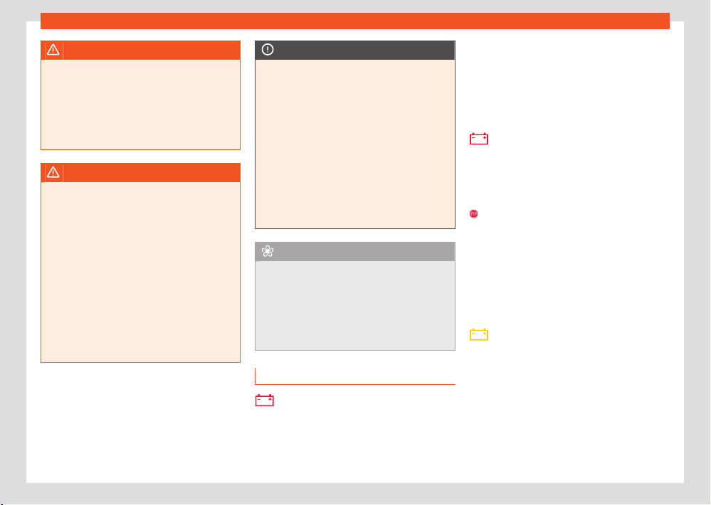
344
Checking and r
efilling levels
WARNING
Attaching the 12-volt battery incorrectly or
using unsuit
able batteries may result in short
circuits, fire and serious injury.
●
Use only maintenance-free 12 volt batter-
ies with an anti-spill system with the same
properties, specifications and dimensions as
the factory-fitted battery.
WARNING
Charging the 12-volt battery creates a highly
e
xplosive mixture of detonating gases.
●
Only charge the 12-volt battery in a well-
ventilated place.
●
Never charge a 12-volt battery that is fro-
zen or has thawed. When the battery is dis-
charged, it may freeze at temperatures close
to 0°C (+32°F).
●
If the 12-volt battery has frozen, have it re-
placed without fail.
●
A short circuit may occur if the wires are
incorrectly connected to the poles. First con-
nect the positive cable and then the negative
one.
NOTICE
●
Never connect or disconnect the 12-volt
batt
ery when the ignition is switched on or
the engine is running. Also, never use a 12-
volt battery that does not meet the vehicle's
battery specifications. The electrical system
or certain electronic components could be
damaged and electrical malfunctions could
occur.
●
Never connect accessories that supply
power, such as solar panels or battery
chargers, to the 12-volt socket or cigarette
lighter, to charge the 12-volt battery. This
could damage the vehicle's electrical sys-
tem.
For the sake of the environment
●
The battery may contain toxic substances,
such as sulphuric acid and l
ead. Dispose of
the 12 volt battery in accordance with the
applicable regulations.
●
Electrolyte can contaminate the environ-
ment. If any operating fluid leaks out, collect
it and dispose of it properly.
Troubleshooting
Alternator fault
Only v
alid for: conventional vehicles.
The control lamp lights up in RED.
The vehicle battery stops charging from the al-
t
ernator. You should immediately drive to the
nearest specialised workshop.
You should avoid using electrical equipment
that is not absolutely necessary because this
will drain the battery.
12 volt battery
The contr
ol lamp lights up in RED. The following
message is displayed:
Error: 12 V battery not charging.
Stop vehicle safely!
St
op driving! Stop the vehicle at the next op-
portunity and in a safe place. The 12-volt bat-
tery will not be charged while driving or there is
a fault in the on-board 12-volt network.
●
Switch o the ignition and any el
ectrical con-
sumers that are not required.
●
Inform a specialised workshop and get the
electrical system checked.
12 volt battery
The indicat
or lamp lights up YELLOW. The fol-
lowing message is displayed:
Error: 12 V vehicle battery. Engine
cannot be started. Go to the work-
shop.
There is a fault in the connection between the
on-board network and the 12-volt battery.

Checking and r
efilling levels
345
Energy management
If the drive system is switched o in this sit
ua-
tion, it cannot be switched on again. If neces-
sary, use the jump leads ›››page318 or seek
assistance from qualified personnel.
●
Have the electrical system checked by a spe-
cialised workshop.
12 volt battery
The indicat
or lamp lights up YELLOW. The fol-
lowing message is displayed:
Low level of the 12 V vehicle bat-
tery. Charge while driving
Starting capacity may be limited. If this driver
message goes out after a certain amount of
time, the vehicle's battery has recharged while
driving and reached a sucient level. If the
driver message does not go out, take the vehi-
cle to a specialized workshop.
12 volt battery
The indicat
or lamp lights up YELLOW. The fol-
lowing message is displayed:
Replace the 12V vehicle battery.
Please visit workshop.
The 12 volt battery has almost reached the end
of its service life.
●
Visit a specialised workshop and have the
12 v
olt battery checked and replaced if neces-
sary ›››page343.
12 volt battery
The indicat
or lamp lights up YELLOW. The fol-
lowing message is displayed:
Check the 12V vehicle battery.
The connection between the electrical system
and the 12-volt vehicle battery does not work.
●
Have the electrical system checked by a spe-
cialised w
orkshop.
12 volt battery
The indicat
or lamp lights up YELLOW. The fol-
lowing message is displayed:
Error: 12 V battery diagnosis.
Please visit workshop.
The system that controls the 12-volt vehicle
battery does not work. Get the electrical sys-
tem checked by a professional.
●
Have the electrical system checked by a spe-
cialised w
orkshop.
Energy management
Optimisation of the starting capacity
The power management controls the distribu-
tion of electrical energy and thus helps to en-
sure that there is always enough power availa-
ble to start the engine.
If a vehicle with a conventional electrical sys-
tem is left parked for a long time, the battery
will gradually lose its charge because certain
electrical devices, such as the electronic gear-
box lock continues to draw current even when
the ignition is o. In some cases there may not
be enough power available to start the engine.
Your vehicle is equipped with an intelligent
power management system to control the dis-
tribution of electrical energy. This significantly
improves reliability when starting the engine,
and also prolongs the useful life of the battery.
The main functions incorporated in the power
management system are battery diagnosis,
residual current management and a dy-
namic power management system.
Battery diagnosis
The battery diagnosis function constantly reg-
isters the condition of the battery. Sensors de-
tect the battery voltage, battery current and
battery temperature. This enables the system to
calculate the current power level and charge
condition of the battery.
Residual current management
The residual current management reduces
power consumption while the vehicle is parked.
It controls the supply of power to the various
electrical devices while the ignition is switched
o. The system takes the battery diagnosis
data into consideration.

346
Checking and r
efilling levels
Depending on the power level of the battery,
s
witch o the individual electrical devices one
after the other to prevent the battery from los-
ing too much charge and to ensure that the
engine can be started reliably.
Dynamic power management
While the vehicle is moving, this function distrib-
utes the available power to the various elec-
trical devices and systems according to their
requirements. The power management ensures
that on-board systems do not consume more
electrical power than the alternator can sup-
ply, and thus maintains the maximum possible
battery power level.
Note
●
Neither is the power management system
abl
e to overcome the given physical limits.
Please remember that the power and useful
life of the battery are limited.
●
When there is a risk that the vehicle will not
start, the alternator power failure or low bat-
tery charge level warning lamp will be shown
›››page344.
Fl
at battery
Starting ability has first priority. Short trips, city
trac and low temperatures all place a heavy
load on the battery.
In these conditions a large amount of power is
consumed, but only a small amount is supplied.
The situation is also critical if electrical devices
are in use when the engine is not running. In this
case power is consumed when none is being
generated.
In these situations you will be aware that the
power management system is intervening to
control the distribution of electrical power.
When the vehicle is parked for long periods
If you do not drive your vehicle for a period
of several days or weeks, the power manage-
ment will gradually shut o the electrical devi-
ces one by one or reduce the amount of cur-
rent they are using. This limits the amount of
power consumed and helps to ensure reliable
starting even after a long period. Some conven-
ience functions, such as remote vehicle open-
ing, may not be available under certain circum-
stances. These functions will be restored when
you switch on the ignition and start the engine.
With the engine switched o
For example, if you listen to the sound system
with the engine switched o the battery will run
down.
If the energy consumption means there is a risk
that the engine will not start, a text will be dis-
played in vehicles with a driver information sys-
tem.
This driver indicator tells you that you must start
the engine so that the battery can recharge.
When the engine is running
Although the alternator generates electrical
power, the battery can still become discharged
while the vehicle is being driven. This can occur
when a lot of power is being consumed but only
a small amount supplied, especially if the bat-
tery is not fully charged initially.
To restore the necessary energy balance, the
system will then temporarily shut o the elec-
trical devices that are using a lot of power, or
reduce the current they are consuming. Heat-
ing systems in particular use a large amount of
electrical power. If you notice, for instance, that
the seat heating or the rear window heater is
not working, they may have been temporarily
switched o or regulated to a lower heat out-
put. These systems will be available again as
soon as sucient electrical power is available.
You may also notice that the engine runs at
a slightly faster idling speed when necessary.
This is quite normal, and no cause for concern.
The increased idling speed allows the alterna-
tor to meet the greater power requirement and
charge the battery at the same time.

Wheels and tyres
347
Important information about wheels and tyres
P
Wheels and tyres
Impor
tant information
about wheels and tyres
General notes
●
When driving with ne
w tyres, be especially
careful during the first 600 km (300 miles).
●
If you have to drive over a kerb or similar ob-
stacle, drive very slowly and as near as possi-
ble at a right angle to the obstacle.
●
Check from time to time if the tyres are
damaged (punctures, cuts, cracks or dents).
Remove any foreign objects embedded in the
treads.
●
Damaged wheels and tyres must be replaced
immediately.
●
Keep grease, oil and fuel o the tyres.
●
Replace any missing valve caps as soon as
possible.
●
Mark the wheels before taking them o so
that they rotate in the same direction when put
back.
●
When removed, the wheels or tyres should be
stored in a cool, dry and preferably dark place.
Low profile tyres
Low profile tyres have a wider tread, a larger
wheel diameter and a lower sidewall height.
Therefore, its driving behaviour is more agile.
Low pr
ofile tyres may deteriorate more quickly
than standard tyres, for instance due to
strong knocks, potholes, manhole covers and
kerbs. Correct tyre pressure is very important
›››page349.
To avoid damage to tyres and wheels, drive
with special care when driving on roads in poor
condition.
Visually check your wheels every 3000 km.
If the tyres or rims have received a heavy im-
pact or have been damaged, have a special-
ised workshop check whether or not it is neces-
sary to change the tyre.
Low profile tyres may deteriorate more quickly
than standard tyres.
Concealed damage
Damage to tyres and rims is often not readily
visible. If you notice unusual vibration or the
car pulling to one side, this may indicate that
one of the tyres is damaged. Reduce speed im-
mediately if there is any reason to suspect that
damage may have occurred. Inspect the tyres
for damage. If no external damage is visible,
drive slowly and carefully to the nearest speci-
alised workshop and have the car inspected.
Foreign objects inserted in the tyre
●
Do not remove foreign bodies if they have
penetrated through the tyre wall!
●
If the vehicle comes with a tyre mobility sys-
tem, where necessary seal the damaged tyre
as shown in section ›››page360. Use a spe-
cialised workshop for repair or replacement.
SEAT recommends visiting a SEAT dealership
for this.
The sealant at the lower part of the tyre tread
wraps around the foreign body and provision-
ally seals the tyre.
Tyres with directional tread pattern
An arrow on the tyre sidewall indicates the di-
rection of rotation on single drive tyres. Always
note the direction of rotation indicated when
mounting the wheel. This makes sure that opti-
mal use is made of tyre properties in terms of
aquaplaning, grip, excessive noise and wear.
Subsequent fitting of accessories
If you wish to change or fit wheels, rims or
wheel trims, we recommend that you consult
with a SEAT Ocial Service for advice regard-
ing current techniques.
Speed symbols
The speed rating indicates the maximum speed
permitted for the tyres.
max.150 km/h (93mph)
348
Wheels and tyres
1)
COC = certificat
e of conformity.
Q
R
S
T
U
H
V
Z
W
Y
max.160 km/h (99mph)
max. 1
70 km/h (106mph)
max.180 km/h (112mph)
max.190 km/h (118mph)
max.200 km/h (124mph)
max. 210 km/h (130mph)
max. 240 km/h (149mph)
max. 240km/h (149mph)
max.270 km/h (168mph)
max.300 km/h (186mph)
WARNING
●
New tyres do not have maximum grip dur-
ing the first 600 km. Driv
e particularly care-
fully to avoid possible accidents.
●
Never drive with damaged tyres. This may
cause an accident.
●
If you notice unusual vibrations or if the ve-
hicle pulls to one side when driving, stop the
vehicle immediately and check the tyres.
●
Never use old tyres or those with an un-
known history of use.
New wheels and tyres
It is best to have all wheels and tyres serviced
by a specialised workshop. There they have the
required knowledge, the special tools and the
corresponding spare parts.
●
Even winter tyres lose their grip on ice. If you
have installed new tyres, drive the first 600 km
carefully and at a moderate speed.
●
All four wheels must be fitted with tyres of the
same type, size (rolling circumference) and, if
possible, tread pattern.
●
When changing tyres, do not change just one;
change at least two on the same axle.
●
If you want to equip your vehicle with a com-
bination tyres and rims that are dierent to
those fitted in the factory, inform your special-
ised workshop before purchasing them ›››
The sizes of the rims and tyres approved for
your v
ehicle are listed in the vehicle documen-
tation (e.g. EC Certificate of Conformity or
COC document
1)
). The vehicle documentation
varies depending on the country of residence.
If the type of spare wheel is dierent form the
normal wheels — e.g. in the case of winter tyres
or particularly wide tyres — the spare wheel
should only be used temporarily in the event
of a puncture, and the vehicle should be driven
with care. Refit the normal road wheel as soon
as possible.
In vehicles with four-wheel drive, the 4 wheels
must be fitted with tyres of the same brand,
type and tread so that the traction system is
not damaged by a dierence in the number of
turns of the wheels. Therefore, in the event of
a puncture, only a spare wheel with the same
perimeter as normal tyres should be used.
Manufacturing date
The manufacturing date is also indicated on
the tyre sidewall (or on the inside face of the
wheel):
DOT ... 2220 ...
it means, for example, that the tyre was manu-
factured in the 22nd week of 2020.
WARNING
●
Use only combinations of tyres and rims,
as w
ell as suitable wheel nuts, approved
by SEAT. Otherwise the vehicle may be dam-
aged, causing an accident.
●
For technical reasons it is not possible to
use wheels of other vehicles; in some ca-
ses not even wheels from the same vehicle
model should be used.
●
Always ensure that the tyres you have
chosen have adequate clearance. When se-
lecting replacement tyres, do not rely en-
tirely on the nominal tyre size marked on the
tyre, since the nominal tyre size can dier
significantly depending on the manufacturer.
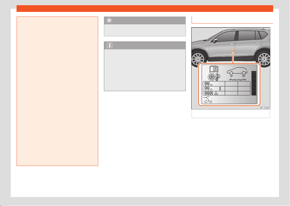
Wheels and tyres
349
Important information about wheels and tyres
Lack of clearance can damage the tyres or
the v
ehicle and, as a result, endanger road
safety. Accident hazard!
●
Only use tyres that are over 6 years old in
an emergency, and drive with due care.
●
The fitting of tyres with run-flat properties
is not permitted on your vehicle! Prohibited
use can cause accidents or can damage
your vehicle.
●
If decorative hubcaps are subsequently fit-
ted, make sure that they allow enough air in
to cool the braking system. Accident hazard!
●
Models with aerodynamic wheel rims
and/or with bolt-on plastic elements (more
closed design) increase the likelihood of ice
and snow accumulating on the inside. This
should be taken into account, depending on
the driving situations, as snow or ice accu-
mulated in the wheels can cause vibration in
the vehicle when it drives at over 40 km/h. It
is advisable to remove ice and snow from the
inside of the wheels using hot water.
●
If you drive on dirt or gravel tracks, the
likelihood of stones becoming trapped inside
wheel rims with plastic elements increases
when driving at high speed or in a sporty
manner. If you see that there are stones trap-
ped between the aluminium wheel rim and
the insert, you can attempt to remove them
using pressurised water.
For the sake of the environment
Old tyres must be disposed of according to
the l
aws in the country concerned.
Note
●
A SEAT Service Centre should be consul-
t
ed to find out whether wheels or tyres of
dierent sizes to those originally fitted by
SEAT can be fitted, and to find out about the
combinations allowed between the front axle
(axle 1) and the rear axle (axle 2).
●
Never mount used tyres if you are not sure
of their “previous history”.
Tyre life
Fig.245 L
ocation of the tyre pressure sticker.
Correct inflation pr
essures and sensible driving
habits will increase the useful life of your tyres.
●
Check tyre pressure at least once a month,
and also prior to any long trip.
●
The tyre pressure should only be checked
when the tyres are cold. Do not reduce the
pressure of warm tyres.
●
Adjust tyre pressure to the load being carried
by the vehicle ›››Fig.245.
●
In vehicles with a tyre pressure indicator, save
the modified tyre pressure ›››page359.
350
Wheels and tyres
●
Avoid fast cornering and hard acceleration.
●
Inspect the tyres for irregular wear from time
t
o time.
Tyre pressure
The values of the tyre pressure are shown on
the sticker label located on the read frame of
the front left door ›››Fig.245.
Insucient or excessive pressure greatly re-
duces the useful life of the tyres and adversely
aects vehicle performance and ride. Correct
inflation pressures are very important, espe-
cially at high speeds.
The tyre pressure must be adjusted according
to the load the vehicle is carrying. If the vehicle
is going to be fully loaded, increase the tyre
pressure to the maximum load value shown on
the sticker label ›››Fig.245.
Do not forget the spare wheel when checking
the tyre pressures: Keep this spare wheel infla-
ted to the highest pressure required for the road
wheels.
In the case of a minimised temporary spare
wheel (125/70 R16 or 125/70 R18) inflate to a
pressure of 4.2 bar as indicated on the tyre
pressure label ›››Fig.245.
Depending on the vehicle, tyre pressure can
be adjusted to medium load to improve driv-
ing comfort (tyre pressure
›››Fig.2
45).
When driving with comfort tyre pressure fuel
consumption may increase slightly.
Driving style
F
ast cornering, heavy acceleration and hard
braking (squealing tyres) all increase tyre wear.
Wheel balance
The wheels on new vehicles are balanced.
However, certain circumstances may lead to
imbalance (run-out), which is detected as vi-
brations in the steering wheel.
Unbalanced wheels should be rebalanced, as
they otherwise cause excessive wear on steer-
ing, suspension and tyres. A wheel must also be
rebalanced when a new tyre is fitted or if a tyre
is repaired.
Incorrect wheel alignment
Incorrect running gear alignment causes ex-
cessive tyre wear, impairing the safety of the
vehicle. If you notice excessive tyre wear, you
should check wheel alignment at a SEAT O-
cial Service.
WARNING
Unsuitable handling of the wheels and tyres
may l
ead to sudden tyre pressure losses, to
tread separation or even to a blow-out.
●
The driver is responsible for ensuring that
all of the vehicle tyres are correctly infla-
ted to the right pressure. The recommen-
ded tyre pressure is indicated on the label
›››Fig.245.
●
Check tyre pressures regularly and ensure
they ar
e maintained at the pressures indica-
ted. Tyre pressure that is too low could cause
overheating, resulting in tread detachment
or even burst tyres.
●
Tyre pressure should be that indicated on
the l
abel when the tyres are cold at all times
›››Fig.245.
●
Regularly check the cold inflation pressure
of the tyres. If necessary, change the tyre
pressure of the vehicle tyres while they are
cold.
●
Regularly check your tyres for damage and
wear.
●
Never exceed the maximum permitted
speed or loads specified for the type of tyre
fitted on your vehicle.
For the sake of the environment
Under-inflated t
yres will increase fuel con-
sumption.
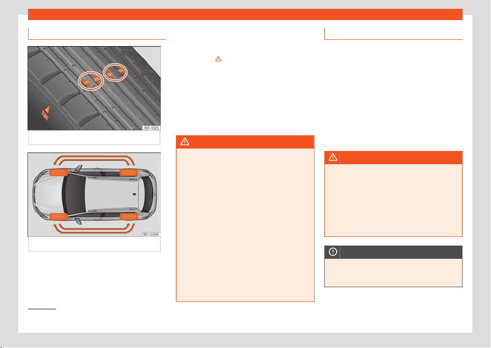
Wheels and tyres
351
Important information about wheels and tyres
1)
Follow the regulations of the country you are driving in.
Tread wear indicators
Fig.246 T
yre profile: tread wear indicators.
Fig.247 Int
erchanging tyres.
Wear indicators around 1.6mm high can be
f
ound on the base of the original tyre treads,
ordered at regular intervals and running across
the tread ›››Fig.246. The letters “TWI” or trian-
gles on the sidewall of the tyre mark the posi-
tion of the wear indicators.
The minimum permitted pr
ofile depth
1)
have
been reached when the tyres have worn down
to the wear indicators. Replace the tyres with
new ones ›››
.
Changing wheel
s around
In order to wear the wheels in a uniform manner,
it is recommended to interchange them regu-
larly according to the diagram ›››Fig.247. The
useful life of all the tyres will then be about the
same time.
WARNING
The tyres must be replaced at the latest
when the tr
ead is worn down to the tread
wear indicators. Failure to follow this instruc-
tion could result in an accident.
●
Particularly in dicult driving conditions
such as wet or icy roads. It is important that
the tyre tread be as deep as possible and be
approximately the same on the tyres of both
the front and the rear axles.
●
The scant driving safety due to insucient
tread depth is particularly evident in vehicle
handling, when there is a risk of “aquaplan-
ing” in deep puddles of water and when driv-
ing through corners, and braking is also ad-
versely aected.
●
The speed has to be adapted accordingly,
otherwise there is a risk of losing control over
the vehicle.
Wheel nuts
The wheel bolts and rims hav
e been designed
to be part of an assembly. When installing
dierent wheels (for instance alloy wheels or
wheels with winter tyres) it is important to use
the correct wheel bolts with the right length
and correctly shaped bolt heads. This ensures
that wheels are fitted securely and that the
brake system functions correctly.
The wheel bolts must be clean and turn easily.
A special adapter is required to turn the anti-
theft wheel bolts ›››page355.
WARNING
Wheel nuts should never be greased or oiled.
●
Use only wheel bolts which belong to the
wheel.
●
If the prescribed torque of the wheel bolts
is t
oo low, they could loosen whilst the vehi-
cle is in motion. Risk of accident! If the tight-
ening torque is too high, the wheel bolts and
threads can be damaged.
NOTICE
See ›››page358 t
o find out the recommen-
ded tightening torque for wheel nuts for steel
and alloy rims.
352
Wheels and tyres
1)
COC = certificat
e of conformity.
Winter tyres
●
Winter tyres must be fitt
ed on all four wheels.
●
Only use winter tyres that are approved for
your vehicle.
●
Please note that the maximum permissible
speed for winter tyres may be lower than for
summer tyres.
●
Also note that winter tyres are no longer ef-
fective when the tread is worn down.
●
After fitting the wheels you must always
check the tyre pressures. When doing so, take
into account the correct tyre pressures lis-
ted on the rear of the front left door frame
›››page349.
In winter road conditions winter tyres will con-
siderably improve vehicle handling. The design
of summer tyres (width, rubber compound,
tread pattern) gives less grip on ice and snow.
This applies particularly to vehicles equipped
with wide section tyres or with high speed
tyres (code letters H, V or Y on the sidewall).
Only use winter tyres of the correct type ap-
proved for your vehicle. The sizes of these tyres
are specified in the vehicle's documents (e.g.
EC Certificate of Conformity or COC
1)
). The ve-
hicle documentation varies depending on the
country of residence.
Winter tyres lose a great deal of their properties
when the tread is worn down to a depth of
4mm.
The performance of winter tyres is also severely
impaired by ageing, even if the tread is still
much deeper than 4 mm.
A code letter indicating the speed limit is stam-
ped on all winter tyres ›››page347.
In the infotainment system's Vehicle settings
menu, a speed warning can be set in the Tyres
menu.
Vehicles capable of exceeding these speeds
must have an appropriate sticker attached so
that it is visible to the driver. Suitable stickers are
available from the SEAT Ocial Service and
specialised workshop. Please note the regula-
tions to this eect in your country.
“All-weather” tyres can also be used instead of
winter tyres.
Using winter tyres with V-rating
Please note that the generally applicable
240km/h (149mph) speed for winter tyres
with the letter V is subject to technical restric-
tions; the maximum permissible speed for
your vehicle may be significantly lower. The
maximum speed limit for these tyres depends
directly on the maximum axle weights for your
car and on the listed weight rating of the tyres
being used.
It is best to contact a SEAT Ocial Service to
check the maximum speed which is permissible
for the V-rated tyres fitted on your car on the
basis of this information.
WARNING
Exceeding the maximum speed permitted for
the wint
er tyres fitted on your car can cause
tyre failure, resulting in a loss of control of
the vehicle – risk of accident.
For the sake of the environment
When winter is over, change back to summer
t
yres at an appropriate moment. In tempera-
tures above +7°C (+45°F), performance will
be improved if summer tyres are used. Rolling
noise, wear and energy consumption will all
be reduced.
Snow chains
Snow chains are only permitted on the front
wheels, even on 4-wheel drive vehicles.
●
Check that they are correctly seated after
driving f
or a few yards; correct the position if
necessary, in accordance with the manufactur-
er's fitting instructions.
●
Keep your speed below 50km/h (30 mph).
●
If there is a danger of being trapped despite
having fitted the chains, it is best to disable the
traction control (TCS) in the ESC ›››page175.
Snow chains will improve braking ability as well
as traction in winter conditions.
Wheels and tyres
353
Changing a wheel
For technical reasons, the use of snow chains
is only permitt
ed on the following rim and tyre
combinations:
Tyres Wheel rim Chains
215/65 R17 6.5x17 ET38 Max. link
13.5mm
215/65 R17 7x17 ET40 Max. link 9 mm
Other dimensions do not allow chains
Remove any central wheel trims before fitting
snow chains.
WARNING
The use of unsuitable or incorrectly fitt
ed
chains could lead to serious accidents and
damage.
●
Always the appropriate snow chains.
●
Observe the fitting instructions provided by
the snow chain manufacturer.
●
Never exceed the maximum permitted
speeds when driving with snow chains.
NOTICE
●
Remove the snow chains to drive on roads
without sno
w. Otherwise they will impair ve-
hicle handling, damage the tyres and wear
out very quickly.
●
Wheel rims may be damaged or scratched
if the chains come into direct contact with
them. SEAT recommends the use of covered
snow chains.
Changing a wheel
Introduction
Only change a wheel yourself if you are famil-
iar with the necessary operations and safety
measures, if you have the necessary tools and if
the vehicle is parked safely.
Preliminary actions
●
Stop the vehicle on a level surface and in a
saf
e place, as far away from road trac as
possible.
●
Apply the electronic parking brake.
●
Switch on the hazard warning lights.
●
Manual transmission: engage 1st gear.
●
Automatic transmission: switch on the parking
lock P.
●
If towing a trailer, unhitch the trailer from your
vehicle.
●
Lay out the on-board tools ›››page316 and
the wheel t
o be changed.
●
Follow the legal provisions of each country
(reflective vest, warning triangles, light beacon,
etc.).
●
Get all occupants out of the vehicle and
keep them out of the danger zone (e.g. behind
the guard rail).
WARNING
●
Always observe the above steps and pro-
t
ect yourself and other road users.
●
If you change the wheel on a slope, block
the wheel on the opposite side of the car with
a stone or similar to prevent the vehicle from
moving.
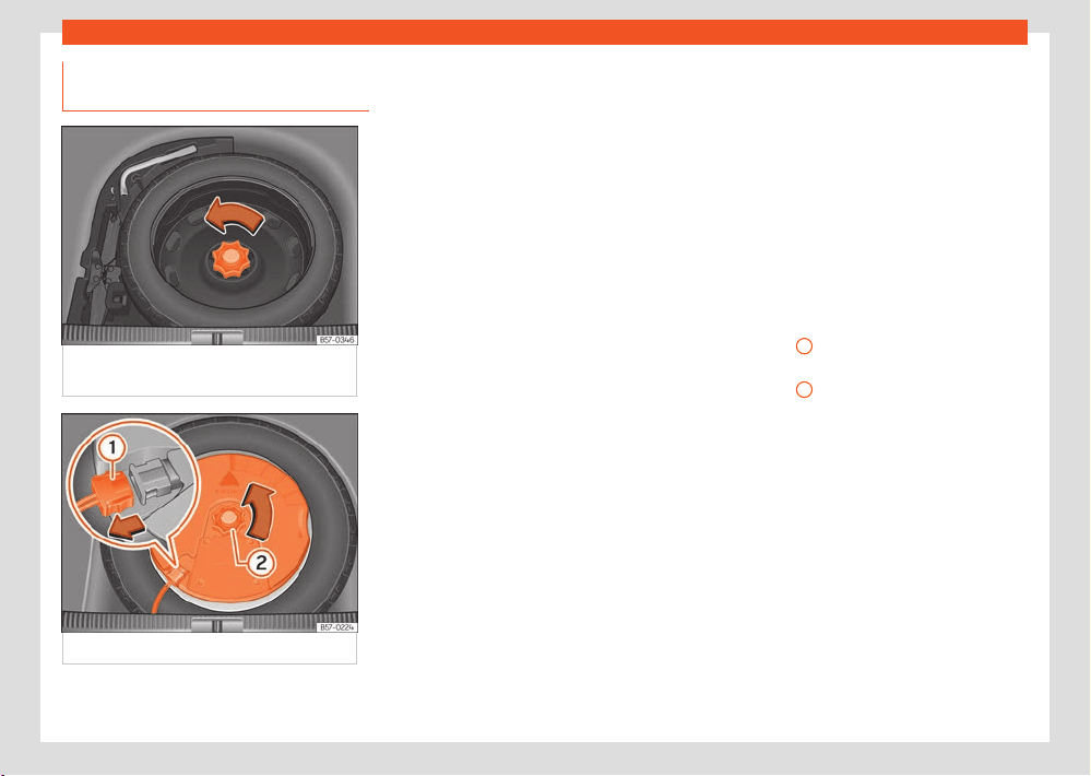
354
Wheels and tyres
Location and use of the temporary
spar
e wheel
Fig.248 In the luggage compartment: r
aised
load floor.
Fig.249 In the boot: r
emove the subwoofer.
The temporary spare wheel is stored under the
floor panel in the luggage compartment and is
att
ached by a thumbnut.
The temporary spare wheel has been designed
to be used for short periods of time. Have the
tyres checked and replaced as soon as possi-
ble at a SEAT Ocial Service or at a special-
ised workshop.
The spare wheel must not be switched for a
spare wheel from another vehicle.
Removing the temporary spare wheel
●
Lift and hold up the floor panel to remove the
temporary spare wheel ›››page290.
●
Turn the thumb wheel anticlockwise
›››Fig.248.
●
Take out the temporary spare wheel.
Removing the temporary spare wheel (7-
seat vehicles)
●
Remove the luggage compartment floor.
●
Pull up on the bottom, side cords of the 3rd
row of seats until latching in the upper position.
●
Remove the transversal side wall.
●
Turn the thumb wheel anticlockwise
›››Fig.248.
●
Take out the temporary spare wheel.
●
To put the temporary spare wheel back in
place, proceed in the reverse order.
Getting the spare wheel out of vehicles fit-
ted with the optional sound system (with
subwoofer)
To remove the spare wheel, you must first re-
move the subwoofer.
●
Vehicles without a variable floor in the lug-
gage compartment: pull the floor of the lug-
gage compartment (carpet) upwards to get it
out.
●
Vehicles with a variable luggage compart-
ment floor: lift and secure the floor storage
compartment as explained in ›››page290.
●
Disconnect the subwoofer’s speaker cable
›››Fig.249
1
.
●
Turn the securing wheel anti-clockwise
›››Fig.2
49
2
.
●
Remove the subwoofer speaker and the
spar
e wheel.
●
When re-mounting the spare tyre, place the
subwoofer on the base of the wheel rim with
care. When doing so, the tip of the “FRONT”
arrow on the subwoofer should point forward.
●
Reconnect the speaker cable and firmly
rotate the securing wheel clockwise so that
the subwoofer system and wheel are firmly in
place.
Chains
For technical reasons, snow chains must not be
used on the temporary spare wheel.
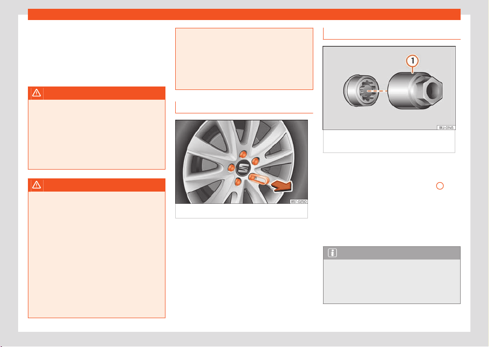
Wheels and tyres
355
Changing a wheel
If you have a puncture on one of the front
wheel
s when using snow chains, fit the tempo-
rary spare wheel in place of one of the rear
wheels. Fit the snow chains on the rear wheel
that you have removed and replace the punc-
tured front wheel with this wheel.
WARNING
Keep in mind that the standard wheel is wider
than the emer
gency spare wheel, so the 3rd
row of seats cannot be completely lowered
when that standard wheel is placed in the
emergency spare wheel well.
●
Do not drive if the 3rd row of seats is not
correctly fastened by the anchors. Risk of se-
rious injury.
WARNING
●
After fitting the t
emporary spare wheel,
check the tyre pressures as soon as possible.
Failure to do so may cause an accident. The
tyre pressure is listed on the back of the left
front door frame ›››page349.
●
Do not drive at over 80km/h (50mph)
when the temporary spare wheel is fitted on
the vehicle: risk of accident!
●
Never travel more than 200km using a
temporary spare wheel.
●
Avoid heavy acceleration, hard braking
and fast cornering: risk of accident!
●
Never use more than one temporary spare
wheel at the same time, risk of accident.
●
No other type of tyre (normal summer or
winter tyre) may be fitted on the compact
temporary spare wheel rim.
●
If you are driving using the spare wheel,
the ACC system could automatically switch
o during the journey. Switch o the system
when starting o.
Wheel bolt caps
Fig.250 Wheel
: wheel bolts with caps.
Removal
●
Fit the plastic clip (vehicle tools ›››Fig.2
18)
over the cap until it clicks into place
›››Fig.250.
●
Remove the cap with the plastic clip.
The caps protect the wheel bolts and should be
remounted after changing the tyre.
The anti-theft wheel locking bolt has a spe-
cial cap. This only fits on anti-theft locking bolts
and is not for use with standard wheel bolts.
Anti-theft wheel nuts
Fig.251 Anti-theft wheel bolt with cap and
adapt
er.
Loosening the anti-theft wheel bolt
●
Remove the wheel trim or hub cap.
●
Insert the special adapter ›››Fig.251
1
(ve-
hicl
e tools ›››page316) onto the anti-theft
wheel bolt and push it on as far as it will go.
●
Insert the wheel brace (vehicle tools) onto
the adapter as far as it will go.
●
Remove the wheel bolt ›››page356.
Note
Make a note of the code number of the anti-
theft wheel bolt and k
eep it in a safe place,
but not in your vehicle. If you need a new
adapter, you can obtain it from the SEAT O-
cial Service, indicating the code number.
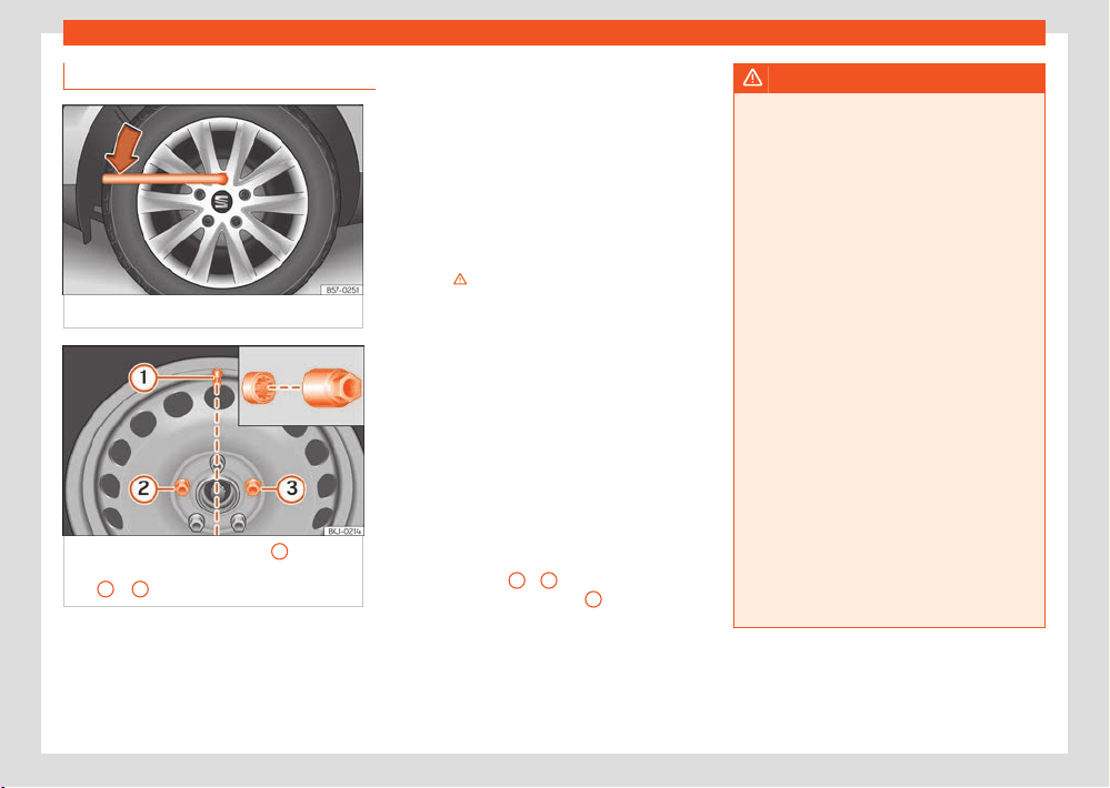
356
Wheels and tyres
Loosening wheel nuts
Fig.252 T
yre change: slacken the wheel bolts.
Fig.253 T
yre change: tyre valve
1
and the
corr
ect position for the anti-theft wheel locking
bolt
2
or
3
.
Use only the wheel wrench belonging to the car
t
o loosen the wheel bolts.
Loosen the wheel bolts only about one turn be-
fore raising the vehicle with the jack.
If the wheel bolt is very tight, carefully push on
the end of the wheel wr
ench with your foot.
Hold on to the vehicle for support and take care
not to slip during this operation.
Loosening wheel nuts
●
Fit the box spanner into the bolt as far as it will
go ›››Fig.252.
●
Hold the wrench at the end and rotate
the bolt approximately one turn anticlock-
wise›››
.
Impor
tant information about wheel bolts
Factory-fitted rims and wheel bolts are spe-
cially matched during construction. Therefore, if
dierent rims are fitted, the correct wheel bolts
with the right length and heads must be used.
This ensures that wheels are fitted securely and
that the brake system functions correctly.
In certain circumstances, you should not even
use wheel bolts from vehicles of the same
model.
On wheels with integral hubcaps, the anti-theft
wheel locking bolt must be screwed in the posi-
tions ›››Fig.253
2
o
3
, taking as reference
the position of the t
yre valve
1
. Otherwise it
will not be possibl
e to mount the hubcap.
WARNING
If the wheel bolts are not properly tightened,
they coul
d come loose while driving and
cause an accident, serious injury and loss of
vehicle control.
●
Use only wheel bolts which correspond to
the rim in question.
●
Never use dierent wheel bolts.
●
Wheel bolts and threads should be clean,
free of oil and grease, and it should be possi-
ble to screw them easily.
●
To loosen and tighten wheel bolts, only
use the wheel wrench that came with the car
from the factory.
●
The wheel bolts should only be loosened
slightly (about one turn) before raising the
vehicle with the jack. Risk of accident!
●
Never apply grease or oil to wheel bolts or
to the wheel hub threads. Even if the bolts
have been tightened to the prescribed tor-
que, they could come loose while driving.
●
Never loosen the screwed joints of wheel
rims with bolted ring trims.
●
If wheel bolts are tightened below the
prescribed torque, the bolts and rims could
come loose while driving. If tightening torque
is too high, the wheel bolts or threads can be
damaged.
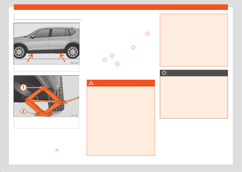
Wheels and tyres
357
Changing a wheel
Raise the vehicle
Fig.254 Jack position points.
Fig.255 Cr
ossbar: mounting the jack on the
vehicle.
●
Rest the jack (vehicles tools) on firm gr
ound.
If necessary use a large, strong board or similar
support. If the surface is slippery (for example
tiles) place the jack on a rubber mat or similar
to prevent it from slipping ›››
.
●
Look on the strut for the mark of the jack sup-
port point (sunk
en area) closest to the wheel to
be changed ›››Fig.254.
●
Turn the jack crank handle, located below the
strut support point, to raise it until the tab
1
›››Fig.255 is bel
ow the housing that is provi-
ded.
●
Align the jack so that the tab
1
“grips” onto
the housing pr
ovided on the cross member and
the mobile base
2
is resting on the ground. The
base pl
ate
2
should fall vertically with respect
t
o the support point
1
.
●
Continue turning the jack until the wheel is
slightly lift
ed o the ground.
WARNING
The factory-supplied jack is only designed
f
or changing wheels on this model. On no
account attempt to use it for lifting heavier
vehicles or other loads. Risk of injury.
●
Make sure the jack remains stable. If the
surface is slippery or soft, the jack could slip
or sink, respectively, with the consequent risk
of causing injuries.
●
Lift the vehicle using only the jack supplied
from the factory. Other jacks, even those ap-
proved for other SEAT models could slip, with
the consequent risk of injury.
●
Place the jack only at the support points
provided on the strut and align it. Otherwise,
the jack could slip because it does not have
sucient grip on the vehicle: risk of injury!
●
You should never place a body limb such as
an arm or l
eg under a raised vehicle that is
solely supported by the jack.
●
If you have to work underneath the vehicle,
you must use suit
able stands additionally to
support the vehicle, there is a risk of acci-
dent!.
●
Never raise the vehicle if it is tilting to one
side or the engine is running.
●
Never start the engine when the vehicle is
raised. The vehicle may come loose from the
jack due to the engine vibrations.
NOTICE
●
The vehicle must not be raised on the
cr
ossbar. Place the jack only at the support
points provided on the strut and align it. Oth-
erwise, the vehicle may be damaged.
●
Any type of load or weight applied to the
external trim/door will (stepped on, fitting
the jack, resting heavy objects, etc.) can
cause damage to it. SEAT accepts no re-
sponsibility for any damages caused by im-
proper use of the external trim or body.
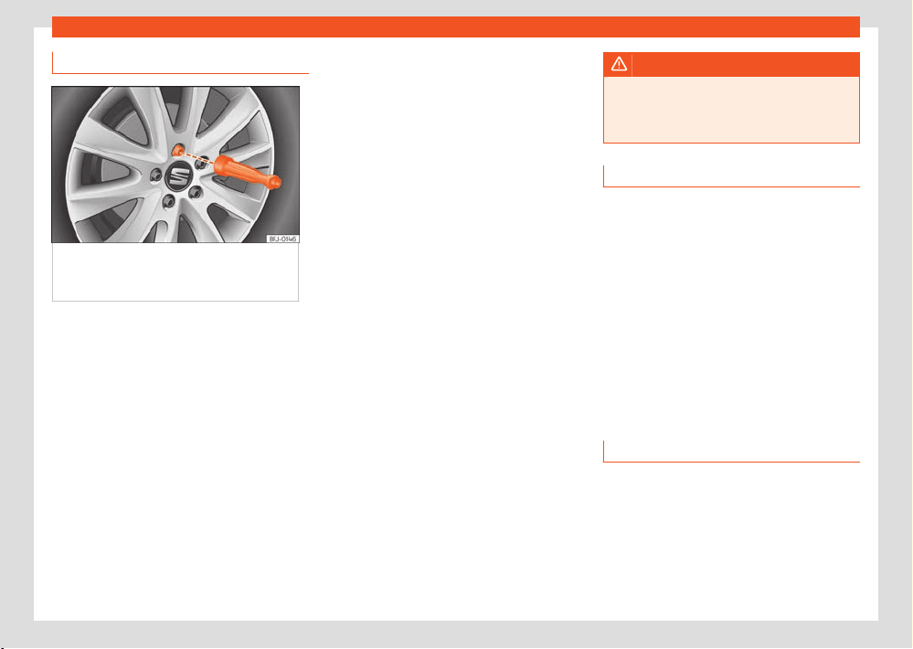
358
Wheels and tyres
Removing and installing a wheel
Fig.256 Changing the wheel
: unscrew wheel
bolts with the socket at the end of the wheel
brace.
Change the wheel after loosening the wheel
bolts and r
aising the vehicle with the jack.
When removing/fitting the wheel, the rim may
hit and damage the brake disc. For this reason,
please take care and get a second person to
assist you.
Taking o the wheel
●
Fully unscrew the loosened wheel bolts with
the inner hexagon of the screwdriver handle
›››Fig.256 and place them on a clean surface.
●
Remove the wheel.
Putting on the spare wheel
Check the direction of rotation of the tyre
›››page358.
●
Place the spare wheel or temporary spare
wheel int
o position.
●
Replace the wheel bolts and tighten slightly
using the hexagonal socket on the end of the
wheel brace.
●
Use the appropriate adapter to tighten the
anti-theft wheel bolts.
●
Carefully lower the vehicle using the jack.
●
Use the wheel spanner to tighten all of the
wheel nuts clockwise. Tighten the bolts in diag-
onal pairs (not in a circle).
●
Put the caps, trim or full hubcap back on.
The wheel bolts should be clean and turn
easily. Before fitting the spare wheel, inspect
the wheel condition and hub mounting surfa-
ces. These surfaces must be clean before fitting
the wheel.
Tightening torque of the wheel nuts
The prescribed tightening torque for wheel
bolts for steel and alloy wheels is 140 Nm. After
changing a wheel, have the tightening torque
checked immediately with a torque wrench that
is working perfectly.
Before checking tightening torque, have any
rusty wheel bolts that are dicult to screw re-
placed and clean the wheel hub threads.
Never apply grease or oil to wheel bolts or to
the wheel hub threads. Even if the bolts have
been tightened to the prescribed torque, they
could come loose while driving.
WARNING
The hexagonal socket in the wheel brace
shoul
d be used for turning wheel bolts only.
Do not use it to loosen or tighten the wheel
bolts.
Tyres with directional tread pattern
Tyres with directional tread pattern have been
designed to operate best when rotating in only
one direction. An arrow on the tyre sidewall in-
dicates the direction of rotation on tyres with
directional tread. Always observe the indicated
direction of rotation in order to guarantee opti-
mum grip and help avoid aquaplaning, exces-
sive noise and wear.
If the tyre is mounted in the opposite direction
of rotation, drive with extreme caution, as the
tyre is no longer being used correctly. This is
of particular importance when the road surface
is wet. Change the tyre as soon as possible or
remount it with the correct direction of rotation.
Works after changing a wheel
●
Replace the hub caps or wheel bolt caps
(depending on equipment).
●
Return all tools to their proper storing loca-
tion.
●
If the replaced wheel does not fit in the spar
e
wheel housing, store it safely in the luggage
compartment ›››page286.
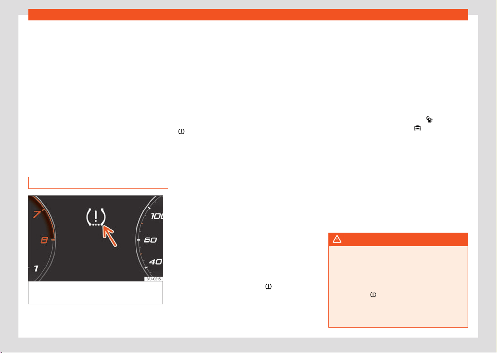
Wheels and tyres
359
Tyre pressure monitor system
●
Check the tyre pressure of the newly moun-
t
ed tyre as soon as possible.
●
In vehicles fitted with a tyre pressure indica-
tor, adjust the pressure and store it in memory
›››page359.
●
Have the tightening torque of the wheel nuts
checked as soon as possible with a torque
wrench ›››page358. Meanwhile, drive care-
fully.
●
Have the flat tyre replaced as quickly as pos-
sible.
Tyre pressure monitor sys-
tem
Tyre pressure monitor indicator
Fig.257 Instrument panel
: warning of loss of
tyre pressure.
The tyre pressure monitoring system compares
the individual speeds of each wheel and thus
the dynamic r
adius with the help of the ABS
sensors.
If the rolling circumference of one or more
wheels has changed, the tyre pressure monitor-
ing indicator will indicate this on the instrument
panel through a warning lamp and a warning to
the driver ›››Fig.257. When only one specific
tyre is aected, its position within the vehicle
will be indicated.
Loss of pressure: Check left tyre
pressure!
Wheel tr
ead change
The wheel diameter changes when:
●
Tyre pressure is changed manually.
●
Tyre pressure is insucient.
●
The tyre structure is damaged.
●
The vehicle is unbalanced because of a load.
●
The wheels on an axle are subject to a heav-
ier l
oad (e.g. with a heavy load).
●
The vehicle is fitted with snow chains.
●
The temporary spare wheel is fitted.
●
The wheel on one axle is changed.
There may be a delay in the reaction of the tyre
pressure monitoring indicator
or it may not
indicat
e anything under certain circumstances
(e.g. sporty driving, snow-covered or unpaved
roads, or when driving with snow chains).
Calibrate the tyre pressure monitoring indi-
cat
or
After changing the tyre pressure or replacing
one or more wheels, the tyre pressure moni-
toring indicator must be recalibrated. Do the
same, for example, when the front and rear
wheels are swapped.
●
Switch the ignition on.
●
Save the new inflation pressure in the Info-
tainment system: function button
> Vehi-
cle status > Tyres; OR:
> External
settings > Tyres ›››page36.
When driving, the syst
em self-calibrates the
tyre pressure provided by the driver and the
wheels fitted. After a long journey with varied
speeds the programmed values are collected
and monitored.
With the wheels under very heavy loads, the
tyre pressure must be increased to the total
recommended tyre pressure before the calibra-
tion ›››Fig.257.
WARNING
When the tyres are inflat
ed at dierent pres-
sures or at a pressure that is too low then a
tyre may be damaged resulting in a loss of
control of the vehicle and a serious or fatal
accident.
●
If the lamp
lights up, reduce speed im-
mediat
ely and avoid any sudden turning or
braking manoeuvres. Stop when possible,
and check the tyre pressure and status.
360
Wheels and tyres
●
The tyre pressure monitoring system can
only oper
ate correctly if all of the tyres are
inflated to the correct pressure when cold.
●
If a tyre has not been punctured and it does
not have to be changed immediately, drive to
the nearest specialised workshop at a mod-
erate speed and have the tyre checked and
inflated to the correct pressure.
Note
●
Driving for the first time with ne
w tyres at
a high speed can cause them to slightly ex-
pand, which could then produce an air pres-
sure warning.
●
If excessively low tyre pressure is detected
with the ignition on, an audible warning will
sound. In the event that there is a fault in the
system, an audible warning will sound.
●
Driving on unpaved roads for a long pe-
riod of time, or sporty driving, may tempora-
rily deactivate the system. The control lamp
shows a fault, but disappears when road
conditions or the driving style change.
●
Do not only rely on the tyre pressure moni-
toring system. Regularly check your tyres to
ensure that the tyre pressure is correct and
that the tyres are not damaged due to punc-
ture, cuts, tears and impacts/dents. Remove
objects from the tyres only when they have
not pierced the tyres.
●
The tyre pressure monitoring indicator
does not function when ther
e is a fault in the
ESC or ABS ›››page174.
Troubleshooting
Low tyre pressure
The contr
ol lamp switches on yellow.
The inflation pressure of one or more wheels is
much lower than the value set by the driver, or
the tyre has structural damage. In addition, a
audible warning sounds and a text message is
displayed on the instrument panel screen.
●
Stop the vehicle! St
op the vehicle safely
as soon as possible.
●
Check all tyres and pressures.
●
Replace any damaged tyres.
Fault in the tyre pressure loss indicator
The contr
ol lamp flashes for approximately 1
minute and then lights up permanently in yel-
low.
●
If the tyre is inflat
ed correctly, switch the igni-
tion o and on again.
●
Re-calibrate the tyre pressure monitoring sys-
tem ›››page359
●
If the fault continues, go to a specialised
workshop.
Tyre repair
TMS (Tyre Mobility System) puncture
repair kit
The puncture repair kit (Tyre Mobility System)
will reliably seal punctures caused by the pen-
etration of a foreign body of up to about 4 mm
in diameter. Do not remove foreign objects,
e.g. screws or nails, from the tyre.
After inserting the sealant residue in the tyre,
you must again check the tyre pressure about
10 minutes after starting the engine.
You should only use the tyre mobility set if the
vehicle is parked in a safe place, you are famil-
iar with the procedure and you have the nec-
essary tyre mobility set. Otherwise, you should
seek professional assistance.
Do not use the tyre sealant in the following
cases:
●
If the wheel rim has been damaged.
●
In outside temperatures below -20°C (-4°F).
●
In the event of cuts or perforations in the tyre
gr
eater than 4 mm.
●
If you have been driving with very low pres-
sure or a completely flat tyre.
●
If the sealant bottle has passed its use by
date.
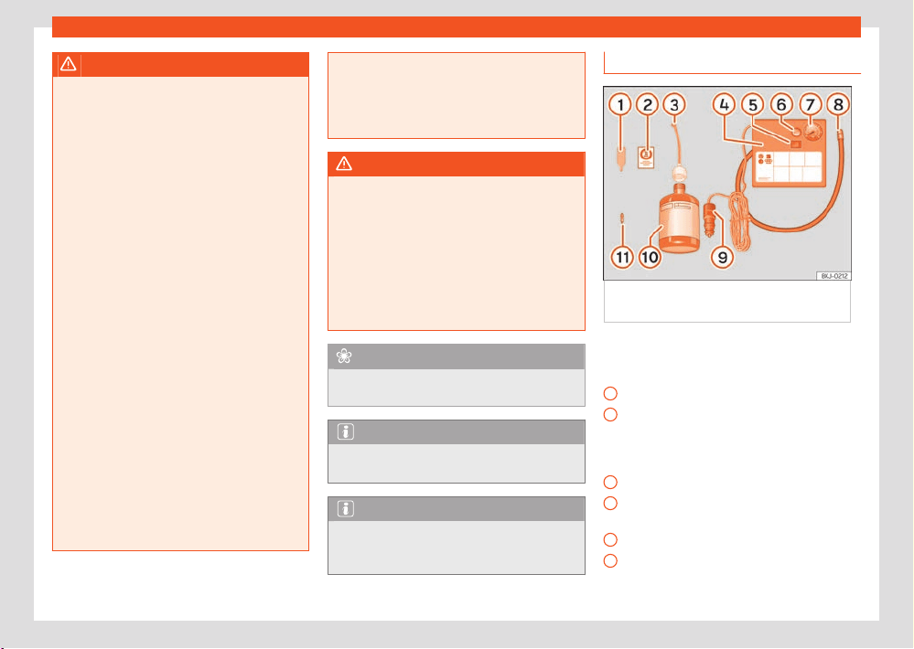
Wheels and tyres
361
Tyre repair
1
2
3
4
5
6
WARNING
Using the puncture repair kit can be danger-
ous, par
ticularly when filling the tyre on the
roadside. To reduce the risk of serious injury,
consider the following:
●
Stop the vehicle safely as soon as possible.
Park it at a safe distance from surrounding
trac to fill the tyre.
●
Ensure the ground on which you park is flat
and solid.
●
All passengers and particularly children
must keep a safe distance from the work
area.
●
Turn on the hazard warning lights to warn
other road users.
●
Always stop the engine, apply the elec-
tronic parking brake and put it in gear if fitted
with a manual gearbox, or press the parking
lock button P if fitted with an automatic gear
box, to reduce the risk of involuntary move-
ment of the vehicle .
●
Use the tyre mobility system only if you
are familiar with the necessary procedures.
Otherwise, you should seek professional as-
sistance.
●
The tyre mobility set is intended for tempo-
rary emergency use only until you can reach
the nearest specialised workshop.
●
Replace the repaired tyre with the tyre mo-
bility set as soon as possible.
●
The sealant is a health hazard and must be
cleaned immediately if it comes into contact
with the skin.
●
Always keep the tyre mobility set out of the
reach of small children.
WARNING
A tyre fill
ed with sealant does not have the
same performance properties as a conven-
tional tyre.
●
Never drive faster than 80km/h (50mph).
●
Avoid heavy acceleration, hard braking
and fast cornering.
●
Drive for only 10 minutes at a maximum
speed of 80 km/h (50mph) and then check
the tyre.
For the sake of the environment
Dispose of used or expired sealant observing
any legal requirements.
Note
A new bottle of sealant can be purchased at
SEAT deal
erships.
Note
Take into account the separate instruction
manual pr
ovided by the tyre mobility system
manufacturer.
Anti-puncture kit contents
Fig.258 St
andard display: contents of the
anti-puncture kit.
The anti-puncture kit is located underneath the
floor co
vering in the luggage compartment. In-
cludes the following components ›››Fig.258:
Valve insert remover
A sticker to be adhered to the instrument
cluster, within the driver's visual field, to re-
mind that the maximum advisable speed
“max. 80 km/h” or “max. 50 mph”
Filler tube with cap
Air compressor (depending on the version,
the model may vary).
ON/OFF switch
Air bleed screw (it can also be integrated in
the inflator tube).
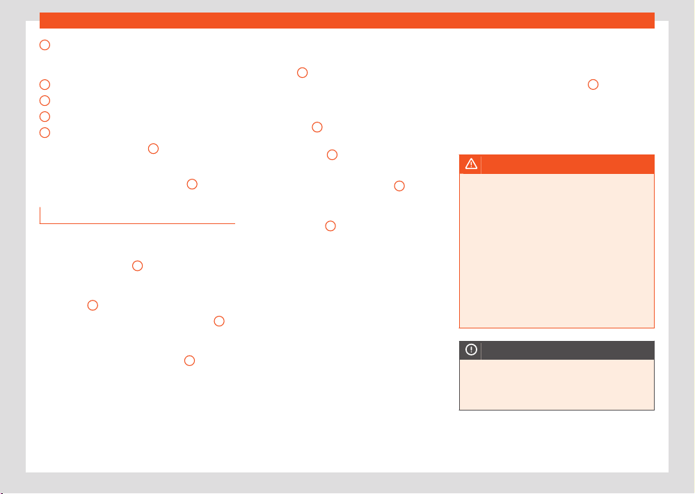
362
Wheels and tyres
7
8
9
10
11
Warning provided by tyre pressure monitor-
ing syst
em (it can also be integrated in the
inflator tube).
Tube for inflating tyres
12 volt connector
Bottle of sealant
Spare tyre valve
The valve insert remover
1
has a gap at the
l
ower end for a valve insert. The valve insert can
only be screwed or unscrewed in this way. This
also applies to its replacement part
11
.
Sealing and inflating a t
yre
Sealing the tyre
●
Unscrew the tyre valve cap and insert. Use
the device ›››Fig.258
1
to remove the valve
cap
. Place it on a clean surface.
●
Shake the tyre sealant bottle vigorously
›››Fig.258
10
.
●
Screw the tyre inflation hose ›››Fig.258
3
into the tyre sealant bottle. The bottle's seal will
br
eak automatically.
●
Remove the filler cap ›››Fig.258
3
and
scr
ew the open end of the tube into the tyre
valve.
●
With the bottle upside down, empty all of the
cont
ents into the tyre.
●
Remove the bottle from the valve.
●
Replace the howitzer with the device
›››Fig.258
1
onto the tyre valve.
Inflating the t
yre
●
Screw the tyre inflation tube of the compres-
sor ›››Fig.258
8
on the tyre valve.
●
Check that the air evacuation screw is
cl
osed ›››Fig.258
6
.
●
Start the engine and leave it running.
●
Attach the connector ›››Fig.258
9
to the
v
ehicle’s 12 volt power outlet ›››page239.
●
Switch on the air compressor with ON/OFF
switch ›››Fig.258
5
.
●
Keep the air compressor running until it rea-
ches a pr
essure of 2.0-2.5 bar (29-36psi/
200-250 kPa). A maximum of 8 minutes.
●
Disconnect the air compressor.
●
If it does not reach the pressure indicated,
unscrew the tyre inflator tube from the valve.
●
Move the vehicle 10m so that the sealant is
distributed throughout the tyre.
●
Screw the compressor tyre inflator into the
valve.
●
Repeat the inflation process.
●
If it still does not come up to pressure, the
tyre is too badly damaged. Stop and seek as-
sistance from authorised personnel.
●
Disconnect the air compressor. Unscrew the
t
yre inflation tube from the tyre valve.
●
When the tyre pressure is between 2.5 and
2.0 bars, continue driving without exceeding
80km/h (50 mph).
●
Attach the sticker ›››Fig.258
2
to the instru-
ment panel displ
ay, within the driver's field of
vision.
●
Check the pressure again after 10 minutes
›››page363.
WARNING
When inflating the wheel, the air compr
essor
and the inflator tube may become hot.
●
Protect hands and skin from hot parts.
●
Do not place the hot flexible inflator tube
or hot air compressor on flammable material.
●
Allow them to cool before storing the de-
vice.
●
If it is not possible to inflate the tyre to at
least 2.0bars (29 psi / 200 kPa), the tyre is
too badly damaged. The sealant is not in a
good condition to seal the tyre. Do not con-
tinue driving. Seek specialist assistance.
NOTICE
Switch o the air compr
essor after a maxi-
mum of 8 operational minutes to avoid over-
heating! Before switching on the air com-
pressor again, let it cool for several minutes.
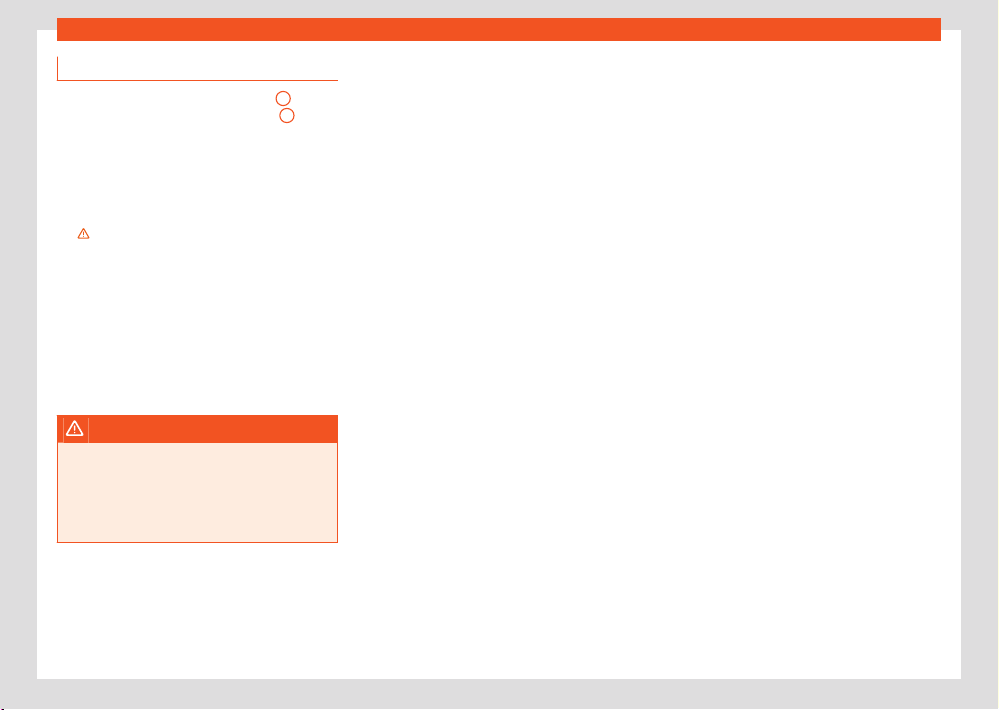
Wheels and tyres
363
Tyre repair
Check after 10 minutes of driving
Scr
ew in the inflator tube ›››Fig.258
8
again
and check the pr
essure on the gauge
7
.
1.3bar (19 psi / 130 kP
a) and lower:
●
Stop the vehicle! The tyre cannot be sealed
suciently with the tyre mobility set.
●
You should obtain professional assistance
›››
.
1.4 bar (20 psi/140 kP
a) and higher:
●
Set the tyre pressure to the correct value
again.
●
Carefully resume your journey until you reach
the nearest specialised workshop without ex-
ceeding 80km/h (50mph).
●
Have the damaged tyre replaced.
WARNING
Driving with an unsealed tyre is dangerous
and can cause accidents and serious injury.
●
Do not continue driving if the tyre pressure
is 1.3bar (19 psi / 130 kP
a) and lower.
●
Seek specialist assistance.
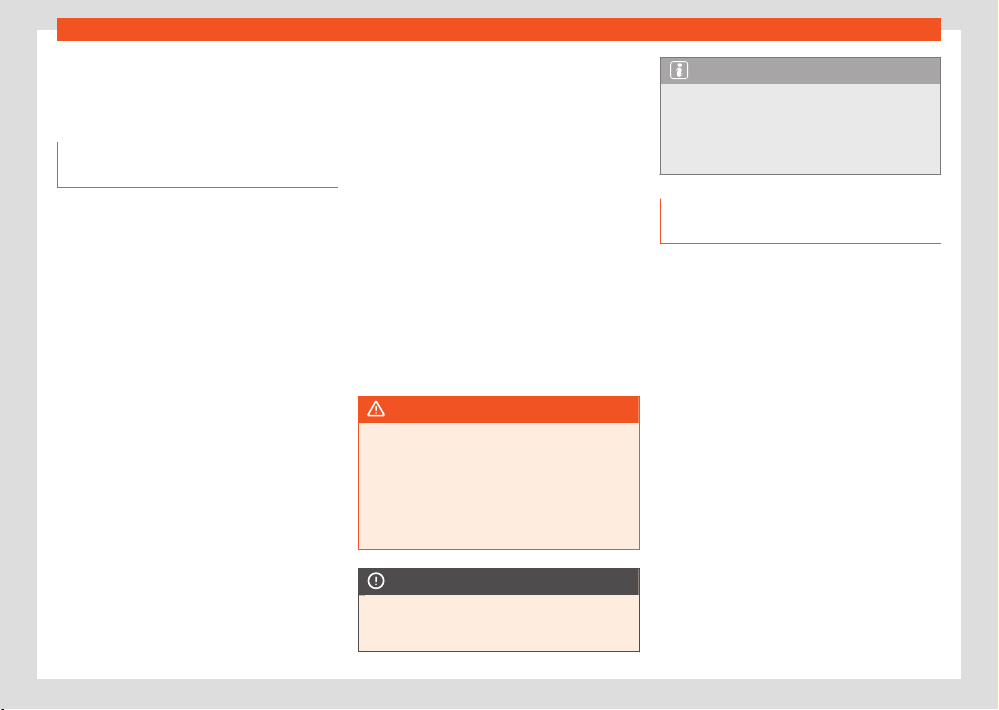
364
Maintenance
Maintenance
Service
Service w
ork and the Digital Mainte-
nance Plan
Log of services performed (“Digital Mainte-
nance Plan”)
The SEAT dealership or a specialised workshop
records Service receipts in a central system.
Thanks to this comprehensive documentation
of the service history, it is possible to reproduce
the services performed any time. SEAT recom-
mends requesting a Service receipt after every
service carried out containing all the services
carried out on the system.
Whenever there is a new service the receipt is
replaced with a current one.
The Digital Maintenance Plan is not availa-
ble in some markets. In this case, your SEAT
dealer will inform you about the current
documentation of the work.
Service works
In the Digital Maintenance Plan, your SEAT au-
thorised service or specialised workshop docu-
ments the following information:
●
When each one of the services was carried
out.
●
Whether a specific r
epair has been sugges-
ted, e.g. changing the brake pads in the near
future.
●
If you have expressed a special request for
the maintenance. Your Service Advisor will write
the work order.
●
The components or fluids that were changed.
●
The date of the next service.
The Long Life Mobility Warranty is valid until the
next inspection. This information is documented
in all checks performed.
The type and the volume of the service may
vary from one vehicle to another. A specialised
workshop will be able to provide specific infor-
mation on the jobs for your vehicle.
WARNING
If the services are insucient or not per
-
formed and if the service intervals are not
observed, the vehicle may be immobilised in
trac cause an accident and severe injuries.
●
Make sure that any repairs are carried out
by a SEAT authorised service or specialised
workshop.
NOTICE
SEAT cannot be held liable for any damage
t
o the vehicle due to insucient work or of
lack of availability of spare parts.
Note
Regular services on the vehicle not only
maint
ain its value, but also its correct opera-
tion and road safety. For this reason, conduct
the services in accordance with SEAT guide-
lines.
Set Service or Flexible Service Inter-
vals
Services are classified as oil change service
and inspection. The service interval display
on the instrument panel display serves as a re-
minder of the next service.
Depending on the features, the engine and the
conditions of use of the car, either the Fixed
service or the Flexible service will be applied
for an oil change service..
How to know which type of service needs to
his vehicle
Check the tables below:
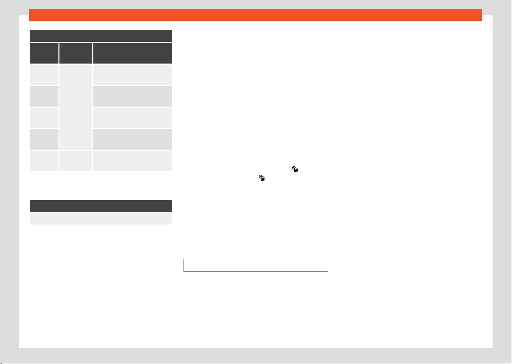
Maintenance
365
Service
Oil change service
a)
PR No.
Type of
service
Service interval
QI1
Fixed
Every 5000km or aft
er
1year
b)
QI2
Every 7500km or after
1year
b)
QI3
Every 10000km or after
1year
b)
QI4
Every 15000km or after
1year
b)
QI6 Flexible
According to the service in-
terval display.
a)
The data are based on normal conditions of use.
b)
Whatever happens first.
Inspection Service
a)
According to the service interval display.
a)
The data are based on normal conditions of use.
Particular characteristics of the Flexible
Service
Regarding the Flexible Service the oil change
service only has to be performed when the ve-
hicle needs it. To calculate when you have to
carry out this service, take into account the in-
dividual conditions of use and personal driving
style. A major component of the flexible service
the use of LongLife oil instead of conventional
engine oil.
Bear in mind the information about the specifi-
cations of the engine oil according to the VW
standard ›››page337.
If you do not want to the flexible service you
can select the fixed service. However, a fixed
service may aect service costs. The Service
Advisor will gladly advise you.
At SEAT, the dates of the services are indicated
by the service intervals display:
●
on the instrument panel ›››page30
●
in the infotainment system: menu
> Set-
tings > Service; OR
> Vehicle sta-
tus > Service ›››page36.
The service int
erval display gives information
for service dates that involve an engine oil
change or an inspection. When the time for the
corresponding service comes, additional work
required, such as the change of brake fluid and
the spark plugs, can be carried out.
Information about the terms of use
The service intervals and groups are usually
based on normal conditions of use.
If, on the other hand, the vehicle is under ad-
verse conditions of use, some of the work
must be carried out before the next service pe-
riod or even between service intervals.
Conditions of use adverse include:
●
The use of fuel with a high sulphur content.
●
Frequent short trips.
●
Letting the engine idle for a long period of
time
, as in the case of taxis.
●
Using the vehicle in areas with thick dust.
●
Frequent driving with a trailer (depending on
equipment).
●
Using the vehicle mostly in situations with a
lot of trac and stops (e.g. in the city).
●
Using the vehicle mostly in winter.
This applies especially for the following
parts (depending on equipment):
●
Dust and pollen filter
●
Air Care allergen filter
●
Air filter
●
Toothed chain
●
Particulate filter
●
Engine oil
The Service Advisor of your specialised
workshop will gladly inform you about the
need of performing service work between nor-
mal service intervals, always considering the
conditions of use of your vehicle.

366
Maintenance
WARNING
If the services are insucient or not per
-
formed and if the service intervals are not
observed, the vehicle may be immobilised in
trac and cause accidents and severe inju-
ries.
●
Have the services conducted at authorised
SEAT services or specialised workshops.
NOTICE
SEAT cannot be held liable for any damage
t
o the vehicle due to insucient work or of
lack of availability of spare parts.
Service sets
Sets of services include all the maintenance
works needed to ensure the safety and the
smooth running of the vehicle (depending on
the conditions of use and the features of the
vehicle, such as the engine, gearbox, or oper-
ating fluids).
Maintenance services are divided into inspec-
tion and review services. Consult the details of
the jobs required for your vehicle at:
●
Your SEAT authorised service
●
Your specialised workshop
Due to technical reasons (continuous develop-
ment of components) the sets of services may
vary. Your SEAT authorised service or special-
ised workshop is always receiving updates in
time.
Additional service oers
Approved spare parts
Original SEAT Spare Parts have been con-
ceived for their vehicles and approved by SEAT,
with a special emphasis on safety. These parts
correspond exactly to the manufacturer's re-
quirements in terms of design, accuracy of the
measurements and materials. The original SEAT
Spare Parts have been conceived exclusively
for your vehicle. For this reason, we always rec-
ommend the use of Original SEAT Spare Parts.
SEAT cannot be held liable for the safety and
suitability of parts from other manufacturers.
Approved spare parts
Approved spare parts, following the manufac-
turer's requirements, are an additional service
to you, oering the possibility of replacing com-
plete sets, such as: light engine, gearboxes,
heads, control units, electrical components,
etc.
These parts are, approved parts, and are the
same as the factory parts, which are also ap-
proved spare parts.
Original accessories
We recommend you only use SEAT Original Ac-
cessories and SEAT approved accessories for
your vehicle. The reliability, safety and suitabil-
ity of these accessories have been inspected
specifically for this type of vehicle. SEAT cannot
be held liable for the safety and suitability of
parts from other manufacturers.
Service Mobility
As of the moment you purchase your SEAT ve-
hicle you will be able to enjoy the benefits and
coverage of Service Mobility.
For the first two years after the purchase, your
new SEAT vehicle is automatically covered by
Service Mobility at no additional cost.
If you wish to enjoy this service after this period,
you can extend SEAT Service Mobility as long
as you carry out the recommended Inspection
and Maintenance Services at a SEAT Author-
ised Service.
If your SEAT vehicle is immobilised due to a fault
or an accident, our assistance services will help
you keep moving.
Take into account that the SEAT Mobility Serv-
ice diers depending on the country in which
the vehicle was purchased. For further informa-
tion ask your SEAT dealership or the SEAT web-
site in your country.
Maintenance
367
Vehicle upkeep and cleaning
Vehicle upkeep and clean-
ing
Basic observ
ations
Regular and careful care helps to maintain the
value of your vehicle. In addition, it may be-
come a prerequisite to demand the warranty
in the event of corrosion damage and deficien-
cies in the paint coat of the bodywork.
Specialised workshops have the necessary
care products. Please follow the instructions for
application on the packaging.
WARNING
●
Cleaning products and other materials
used for car care can be damaging to your
health if misused.
●
Always keep care products in a safe place,
out of the reach of children. Danger of poi-
soning!
For the sake of the environment
●
When purchasing car care products, chose
products that are compatible with the envi-
ronment.
●
The waste from car-care products should
not be disposed of with ordinary household
waste.
Washing the vehicle
The l
onger you take to clean the tanks, e.g. re-
mains of insects, bird excrements, tree resin or
anti frost salt adhered to your vehicle, the more
damage it can cause to the surface. High tem-
peratures, for instance strong sunlight, further
intensify the damage.
Before washing the car, soften the dirt using
plenty of water.
To remove encrusted dirt such as insects, bird
droppings or tree resin, use a lot of water and a
microfibre cloth.
Have the underside of the vehicle washed after
the end of the anti frost salts in winter.
High pressure cleaning equipment
When washing the vehicle with a high-pressure
cleaner, always follow the operating instruc-
tions for the equipment. This applies particu-
larly to the operating pressure and the distance
between the spraying water. Do not aim the
jet directly towards the side windows, doors,
sunroof or covers; the same applies for the
tyres, rubber hoses, damping material, sensors
or camera lenses. Keep a distance of at least
40cm.
Do not remove snow and ice with a high-pres-
sure cleaner.
Do not use a nozzle that sprays the water out in
a direct stream or one that has a rotating jet for
forcing o dirt.
The water temperature must not exceed 60°C.
Automatic car washes
Spray the vehicle before starting the car wash.
Make sure that the windows and sunroof are
closed and the wipers are deactivated. Bear
in mind the instructions of the car wash tunnel
operator, especially if your vehicle has detach-
able parts.
Use of car washes without brushes if possible.
Washing by hand
Clean your vehicle from top to bottom with a
soft sponge or with a brush. Only use cleaning
products that do not contain solvents.
Polishing
Polishing is only necessary when the vehicle's
paintwork has lost its gloss and cannot be re-
stored with care products.
Do not polish matt painted surfaces! If the
paintwork is polished, the surface will be irrep-
arably damaged.
Washing vehicles with a matte paint by hand
To prevent damage to the vehicle when wash-
ing it, first remove the thicker dust and dirt.
To remove traces of insects, grease and finger-
prints, it is best to use a special cleaner for
matte paint.
368
Maintenance
Apply the product with a micr
ofibre cloth. To
avoid damaging the surface of the paint, do not
apply too much pressure.
Rinse with plenty of water. Then clean it with a
neutral cleaning product and a soft microfibre
cloth.
Rinse the vehicle again with plenty of water and
then leave it to dry. Remove traces of water
with a leather cloth.
WARNING
●
Only wash the vehicle with the ignition
s
witched o or according to the specifica-
tions of the car wash tunnel operator. Acci-
dent hazard!
●
When cleaning the underbody or the inside
of the wheel arches, protect yourself from
sharp or pointy metal parts. Risk of cut!
●
After cleaning the brakes could act more
slowly due to moisture or, in winter, the ice on
the brake discs and pads. Accident hazard!
In this case the brakes should be dried by
pressing the brake pedal several times.
WARNING
Incorrect use of high-pressure cleaning
equipment can cause damage
. This can lead
to accidents and serious injuries.
●
Never direct the jet of the high-pressure
cleaning equipment directly at the orange
high-voltage cables, the high-voltage sys-
tem components or the 12-volt on-board net-
work.
NOTICE
●
Before washing the vehicle in an automatic
car w
ash, please make sure to retract the
exterior mirrors to prevent them from being
damaged. The electric folding exterior mir-
rors should only be folded/unfolded electri-
cally!
●
Do not wash the vehicle in direct sunlight.
Risk of damaging the paint job!
●
Do not use sponges, abrasive household
sponges or similar to clean insect remains.
Risk of damaging the surface!
●
Vehicle parts with matte paint:
–
Do not use polish or hard wax. Risk of
damaging the surface!
–
Never select washing programmes that
include the use of wax. This could damage
the appearance of matte paint.
–
Do not put stickers or magnets on parts
with matte paint, as removing them may
damage the paint.
For the sake of the environment
The car should only be washed in special
w
ash bays. These places are prepared to
prevent oily water from getting into the pub-
lic drains.
Cleaning and maintenance instruc-
tions
The cleaning and maintenance of individual
components of the vehicle can be checked in
the following tables. The contents should be
understood merely as a recommendation. Go
to your specialised workshop if you have spe-
cial questions or parts that are not listed. Take
he general considerations into account ›››
in
T
ake special care with... on page372.
Cleaning the exterior
Windscreen wipers
Problem Solution
Dirt Soft cloth with wipers

Maintenance
369
Vehicle upkeep and cleaning
Headlights / Tail lights
Problem Solution
Dirt
Soft sponge with neutral
soap solution
a)
a)
Neutr
al soap solution: two tablespoons maximum
in 1 litre of water
Sensors / Camera lenses
Problem Solution
Dirt
Sensors: soft cloth with
a solvent-free cleaning
product
Camera lenses: soft cloth
with an alcohol-free
cleaning product
Snow/ice
Hand brush/Anti frost
spray with no solvents
Wheels
Problem Solution
Antifreeze salt Water
Brake abrasion dust
Acid-free special cleaning
product
End exhausts
Problem Solution
Antifreeze salt
Water, if a steel clean-
ing product is required, or
a non-abrasive and non-
corrosive cleaning product
Covers / Trims
Problem Solution
Dirt
Neutral soap solution
a)
, if
a steel cleaning product is
required
a)
Neutral soap solution: two tablespoons maximum
in 1 litre of water
Paint
Problem Solution
Paint flaws
Check the paint's colour
code in an authorised
service and restore with a
touch-up pencil
Spilled fuel
Immediately rinse with wa-
ter
Environmental rust
tank
Apply rust remover and
then apply hard wax. Go
you your specialised work-
shop if you have any quer-
ies
Problem Solution
Corrosion
Have your specialised
workshop take care of this
The water does not
create droplets on
the clean paint
Maintain with hard wax (at
least 2 times a year)
No shine de-
spite sober mainte-
nance/paint
Treat with suitable wax and
apply paint preservative
afterwards if the wax used
does not contain preser-
vative ingredients
Tanks, e.g. insect
remains, bird drop-
pings, tree sap, road
salt
Immediately soften with
water and remove with a
microfibre cloth
Fat-based dirt, e.g.
cosmetic products or
sunscreen
Remove immediately with
a neutral soap solution
a)
and a soft cloth
a)
Neutral soap solution: two tablespoons maximum
in 1 litre of water
Carbon fibre parts
Problem Solution
Dirt
Clean the same way
as painted parts
›››page367
370
Maintenance
Decoration slides
Problem Solution
Dirt
Soft sponge with neutral
soap solution
a)
a)
Neutr
al soap solution: two tablespoons maximum
in 1 litre of water
Interior cleaning
Windows
Problem Solution
Dirt
Apply windscreen cleaner
and then dry with a cl
oth
Covers / Trims
Problem Solution
Dirt Neutral soap solution
a)
a)
Neutral soap solution: two tablespoons maximum
in 1 litre of water
Plastic parts
Problem Solution
Dirt Damp cloth
Problem Solution
Encrusted dirt
Neutral soap solution
a)
, if
possibl
e solvent-free plas-
tic cleaner
a)
Neutral soap solution: two tablespoons maximum
in 1 litre of water
Displays/instrument panel
Problem Solution
Dirt
Soft cloth with a liquid
crystal display cleaner
Control panels
Problem Solution
Dirt
Soft brush, then soft cloth
with neutral soap solution
a)
a)
Neutral soap solution: two tablespoons maximum
in 1 litre of water
Seat belts
Problem Solution
Dirt
Neutral soap solution
a)
,
allowed to dry before re-
tracting
a)
Neutr
al soap solution: two tablespoons maximum
in 1 litre of water
Fabrics, ar
tificial, Alcantara leather
Problem Solution
Particles of dirt stuck
to surfaces
Vacuum cleaner
Water-based dirt, e.g.
coee, tea, blood
etc.
Absorbent cloth and neu-
tral soap solution
a)
Grease-based dirt,
e.g. oil, make-up, etc.
Apply a neutral soap sol-
ution
a)
. Absorb the dis-
solved grease and paint
particles dryingwith an
absorbent cloth, in case
you must treat it with water
afterwards
Special dirt, e.g.
pens, nail polish, dis-
persion paint, shoe
cream etc.
Special stain remove: dry
with an absorbent cloth, if
applicable, apply neutral
soap solution afterwards
a)
a)
Neutral soap solution: two tablespoons maximum
in 1 litre of water
Natural leather
Problem Solution
Recent dirt
Cotton cloth with neutral
soap solution
a)
Water-based dirt, e.g.
coee, tea, blood
etc.
Recent stains: absorbent
cloth
Dry stains: stain remover
suitable for leather

Maintenance
371
Vehicle upkeep and cleaning
Problem Solution
Grease-based dirt,
e
.g. oil, make-up, etc.
Recent stains: absorbent
cloth and suitable stain re-
mover for leather.
Dry stains: grease solvent
spray
Special dirt, e.g.
pens, nail polish, dis-
persion paint, shoe
cream etc.
Stain remover suitable for
leather
Care
Apply preservative cream
regularly to protect from
sunlight. Use a colour
preservative if required
a)
Neutral soap solution: two tablespoons maximum
in 1 litre of water
Carbon fibre parts
Problem Solution
Dirt Clean like plastic parts
Take special care with...
Headlights/tail lights
●
Do not clean the headlights/tail lights with a
dry cl
oth or sponge.
●
Do not use cleaning products that contain
alcohol. Risk of cracks!
Wheels
●
Do not use for paint wax or other abrasive
pr
oducts.
●
If the protective coating on the paint of the
rim has been damaged due to stone impacts,
scratches, etc., the damage should be repaired
immediately.
Camera lenses
●
Do not use hot or warm water to remove ice
or snow from the camera lenses. Risk of crack-
ing the lens!
●
To clean the camera lens, never use abra-
sive cleaning products or products with alcohol.
Risk of scratches and cracks!
Windows
●
Remove snow and ice from windows and ex-
terior mirrors with a plastic scraper only. To
avoid scratches, the scraper should only be
pushed in one direction and not moved to and
fro.
●
Never remove snow or ice from windows and
rearview mirrors with warm or hot water. Risk of
cracks on the windows!
●
To prevent damage to the heating of the rear
window, do not put stickers over the heating
elements.
Covers/trims
●
Do not use cleaning products or chrome
based cleaning agents.
Paint
●
The vehicle must be free from dirt and dust
before applying wax or care products. Risk of
scratches!
●
Do not apply wax or care products if the vehi-
cle is exposed to direct sunlight. Risk of damag-
ing the paint job!
●
The ambient rust deposits must not be re-
moved through friction. Risk of damaging the
paint job!
●
Remove cosmetic products and sunlight im-
mediately. Risk of damaging the paint job!
Displays/instrument panel
●
The displays, the instrument panel and the
trim around it must not be cleaned dry. Risk of
scratches!
●
Make sure that the instrument panel is
switched o and cooled down before cleaning.
●
Make sure that no liquid leaks between the
instrument panel and the trim. Risk of damage!
Control panels
●
Make sure that no liquid leaks into the control
panels. Risk of damage!
372
Maintenance
Seat belts
●
Do not remove the seat belts to clean them.
●
Seat belts and their components must never
be cl
eaned with chemical products, nor should
they be allowed to come into contact with cor-
rosive liquids, solvents or sharp objects. Risk of
damaging the fabric!
●
If you find any damage to the belt webbing,
belt fittings, the belt retractor or the buckle, ask
your specialised workshop to replace the belt
in question.
Fabrics/artificial leather/microfibre
●
Do not treat artificial leather/microfibre with
leather cleaning products, solvents, wax polish,
shoe cream, stain removers or similar products.
●
If the stain is very hard to remove, take the
vehicle to a specialised workshop to have it re-
moved there. This will prevent damage.
●
Do not use steam cleaners, brushes, hard
sponges, etc. to clean.
●
Do not turn on seat heating to dry the seats.
●
Sharp objects on clothing, such as zips, rivets
or belts can damage the surface.
●
Open Velcro, e.g. on clothes can damage the
seat upholstery. Make sure that Velcro fasten-
ers are closed.
Natural leather
●
Never use solvents, wax polish, shoe cream,
spot removers or similar products on leather.
●
Sharp objects on clothing, such as zips, rivets
or belts can damage the surface.
●
Do not use steam cleaners, brushes, hard
sponges, etc. to clean.
●
Do not turn on seat heating to dry the seats.
●
Avoid exposing leather to direct sunlight for
long periods, otherwise it may tend to lose
some of its colour. If the car is left for a pro-
longed period in the bright sun, it is best to
cover the leather.
WARNING
Do not use water-repellent coatings on the
windscr
een. In bad visibility conditions such
as humid weather, darkness or when the sun
is in its lowest point, visibility may be impac-
ted. Accident hazard! Such coatings can also
cause the windscreen wiper blades to make
noise.
Note
●
Remains of insects can be removed much
mor
e easily with previously treated paint.
●
Regular car care treatments can prevent
deposits of ambient rust.
Remove the vehicle from trac
If you want to leave your vehicle stationary
for a long period of time, contact a qualified
workshop. They will gladly inform you about
the necessary measures, such as anti-corrosion
protection, Service and storage.
Also take into account the indications relat-
ing to the vehicle’s battery ›››page341 ,
›››page341, Introduction.
Accessories, spare parts
and repair work
Introduction
Always ask your dealer or specialist retailer for
advice before purchasing accessories and re-
placement parts.
Your vehicle is designed to oer a high standard
of active and passive safety. For this reason, we
recommend that you ask a SEAT Ocial Serv-
ice for advice before fitting accessories or re-
placement parts. Your SEAT Ocial Service has
the latest information from the manufacturer
and can recommend accessories and replace-
ment parts which are suitable for your require-
ments. They can also answer any questions
you might have regarding ocial regulations.
We recommend only using SEAT accessories
and genuine SEAT parts®. SEAT has tested
these parts and accessories for suitability, reli-
Maintenance
373
Accessories, spare parts and repair work
ability and safety. SEAT Ocial Services hav
e
the necessary experience and facilities to en-
sure that the parts are installed correctly and
professionally.
Although SEAT continuously monitors the mar-
ket, it cannot judge whether products not au-
thorised by SEAT meet the vehicle’s reliability,
safety and suitability requirements. SEAT there-
fore accepts no liability for these products,
even if, in certain cases, they are authorised
by an ocially recognised technical inspection
institute or ocial body.
Any retro-fitted equipment which has a di-
rect eect on the vehicle and/or the way it
is driven, such as a cruise control system or
electronically-controlled suspension, must
be approved for use in your vehicle and bear
the e mark (the European Union's authorisation
symbol).
If any additional electrical devices are fitted
which do not serve to control the vehicle itself
(for instance a refrigerator box, laptop or venti-
lator fan, etc.), they must bear the
marking
(manuf
acturer conformity declaration in the Eu-
ropean Union).
WARNING
Accessories, for example telephone holders
or cup hol
ders, should never be fitted on the
covers, or within the working range of the air-
bags. Otherwise, there is a danger of injury if
the airbag is triggered in an accident.
Technical modifications
Unauthorised modifications to the electronic
components, software, wiring or data transfer
in the vehicle may cause malfunctioning.
You will appreciate that your SEAT dealership
cannot be held liable for any damage caused
by modifications and/or work performed incor-
rectly.
For this reason we recommend asking ocial
SEAT service centres to do any necessary work
using genuine SEAT parts®.
WARNING
Incorrectly performed modifications or other
w
ork on your vehicle can lead to malfunc-
tions and cause accidents.
Radio telephones and oce equip-
ment
Radio transmitters (fixed installation)
Any retrofit installations of radio transmitters
in the vehicle require prior approval. SEAT gen-
erally authorises in-vehicle installations of ap-
proved types of radio transmitters provided
that:
●
The antenna is installed correctly.
●
The aerial is installed on the exterior of the
v
ehicle (and shielded cables are used together
with non-reflective aerial trimming).
●
The eective transmitting power does not ex-
ceed 10 Watts at the aerial base.
A SEAT Ocial Service and specialised work-
shop will be able to inform you about options
for installing and operating radio transmitters
with a higher transmitting power.
Mobile radio transmitters
Commercial mobile telephones or radio equip-
ment might interfere with the electronics of your
vehicle and cause malfunctions. This may be
due to:
●
No external aerial.
●
External aerial incorrectly installed.
●
Transmitting power more than 10 W.
You must, therefore, do not operate portable
mobile telephones or radio equipment inside
the vehicle without a properly installed external
aerial ›››
.
Pl
ease note also that the maximum range of
the equipment can only be achieved with an
external aerial.
Business equipment
Retrofit installation of business or private equip-
ment in the vehicle is permitted, provided the
equipment cannot interfere with the driver's im-
374
Maintenance
mediate control of the vehicle and that any
such equipment carries the mark. Any retro-
fit equipment that coul
d influence the driver's
control of the vehicle must have a type appro-
val for your vehicle and must carry the e mark.
WARNING
Mobile telephones or radio equipment which
is oper
ated inside the vehicle without a prop-
erly installed external aerial can create ex-
cessive magnetic fields that could cause a
health hazard.
Note
●
The posterior fitting of el
ectric and elec-
tronic equipment in this vehicle aects its li-
cence and could lead to the withdrawal of
the vehicle registration document under cer-
tain circumstances.
●
Please use the mobile telephone/radio op-
erating instructions.

Information for the user
375
Information stored by the control units
Information for the user
W
arranty
Fault-free operation warranty
SEAT Authorised Services ensure the perfect
condition of new vehicles. Check the purchase
agreement or complementary additional docu-
mentation provided by your Technical Service
to see the conditions and the terms of the war-
ranty. Consult further information in this regard
in your SEAT Ocial Service.
Commercial warranty for high volt-
age batteries for electric and hybrid
vehicles
To supplement the aforementioned warranties
and guarantees, SEAT Ocial Services also
grant a guarantee for high voltage batteries ex-
isting in many countries.
Consult the details of this guarantee in the
sales contract or contact a SEAT Ocial Serv-
ice.
Information stored by the
control units
Storage of accident data (Event Data
Recorder)
Your vehicle has an event data recorder (EDR).
The EDR’s function is to record data in the event
of a mild or serious accident. These data are
used to support the analysis of how dierent
vehicle systems behaved.
The EDR records, over a reduced time range
(normally 10 seconds or less), dynamic driving
data and data from the restraint systems, such
as:
●
How dier
ent vehicle systems worked.
●
Whether the driver and the occupants were
wearing their seat belts.
●
How hard the acceleration or brake pedal
was pressed.
●
Vehicle speed.
●
GPS position.
These data will provide a better understanding
of the circumstances of the accident.
Data from the driving assist systems are also
recorded. This includes data such as whether
the systems were inactive or active and if such
action had an impact on the vehicle’s dynamic
behaviour, changing its path in the aforemen-
tioned sit
uations, accelerating or decelerating
the vehicle.
Depending on vehicle equipment, this includes
data from systems such as:
●
the adaptive cruise control
●
the lane assist system
●
parking assistants
●
the emergency brake functions.
The EDR data are only recorded in specific ac-
cident situations. No data are recorded in nor-
mal driving conditions.
No audio or video data inside or around the
vehicle are recorded. Under no circumstances
are personal data such as name, age, or gen-
der recorded. Nevertheless, third parties (such
as criminal proceedings authorities) may relate
the contents of the EDR data to other data
sources and create a personal reference in the
context of an accident investigation.
In order to read the EDR data it is necessary
to access (if legally permitted to do so) the
vehicle's ODB (“On-Board-Diagnose”) interface
while the vehicle is switched on.
SEAT will not have access to EDR data unless
the owner (or, in “Leasing” cases, the lessee or
hirer) gives their consent. There may be excep-
tions to this, depending on legal or contractual
provisions.
376
Information for the user
Due to legal requirements in safety-related
pr
oducts, SEAT may use the EDR data for field
research and in order to improve vehicle system
quality. Any data used for the purposes of re-
search will be treated anonymously (in other
words, no reference will be made to the vehicle,
their owner or the lessee/hirer).
Vehicle antennas
Infotainment system and antennas
The infotainment system's antennas are instal-
led on dierent locations on the vehicle:
●
On the roof.
●
On the windscreen, between the layers of
gl
ass.
●
On the rear and side windows with a printed
antenna structure ››› .
NOTICE
The printed antenna structure on the rear
and side windows can be damaged by ob-
jects rubbing against it or by the use of
corrosive products, or products containing
acids.
●
Do not apply any stickers to the rear and
side window areas.
●
Never clean the antenna structure with
corrosive or acidic products.
Materials and recycling in-
f
ormation
Environmental compatibility
Environmental protection is a top priority in the
design, choice of materials and manufacture of
your new SEAT.
Constructive measures to encourage recy-
cling
●
Joints and connections designed for easy
dismantling.
●
Modular construction to facilitate disman-
tling.
●
Increased use of single-grade materials.
●
Plastic parts and elastomers are marked in
accor
dance with ISO 1043, ISO 11469 and ISO
1629.
Choice of materials
●
Use of recycled materials.
●
Use of compatible plastics in the same part if
its components are not easily separated.
●
Use of recycled materials and/or materials
originating from renewable sources.
●
Reduction of volatile components, including
odour, in plastic materials.
●
Use of CFC-free coolants.
Ban on heavy metals, with the exceptions
dict
ated by law (Annex II of ELV Directive
2000/53/EC): cadmium, lead, mercury, hexa-
valent chromium.
Manufacturing methods
●
Reduction of the quantity of thinner in the
protective wax for cavities.
●
Use of plastic film as protection during vehi-
cle transport.
●
Use of solvent-free stickers.
●
Use of CFC-free coolants in cooling systems.
●
Recycling and energy recovery from residues
(RDF).
●
Improvement in the quality of waste water.
●
Use of systems for the recovery of residual
heat (thermal recovery, enthalpy wheels, etc.).
●
The use of water-soluble paints.
Recycling of electrical or electronic
devices
All electrical or electronic devices (EED) that
are not permanently fitted in the vehicle must
be marked with the following symbol:
This symbol indicates that EED must not be dis-
car
ded as home waste but through selective
waste collection.
Information for the user
377
Radioelectrical equipment
Product recycling
For the sake of the environment
The Triman logo and the Infotri symbol con-
t
ain important information for the classifica-
tion of the end consumer.
Radioelectrical equipment
Simplified decl
aration of conformity
Your vehicle has dierent radioelectrical de-
vices. The manufacturers of these devices
declare that they comply with Directive
2014/53/EU when legally required.
The full text of the EU compliance declaration is
available online at the following address:
www.seat.com/generalinfo
United Kingdom
Your vehicle has dierent radioelectrical devi-
ces. The manufacturers of these devices de-
clare that they comply with the UK Radio
Equipment Regulations 2017 (SI 2017/1206) if
required by law.
The full text of the declaration of conformity
is available online at the following Internet ad-
dress:
www.seat.com/generalinfo
Ukraine
Your vehicle has dierent radioelectrical devi-
ces. The manufacturers of these devices de-
clare that they comply with Ukraine Decree
355/2017 (TR Radio Equipment) where legally
required.
The full text of the declaration of conformity
is av
ailable online at the following Internet ad-
dress:
www.seat.com/generalinfo
Addresses of the manufacturers
The addr
ess of the manufacturers of compo-
nents that, due to their size or nature, cannot
include a sticker are listed below, as long as it is
legally required:
Central control unit (BCM)
Robert Bosch GmbH/Braunschweig
Theodor-Heuss-Strasse 12
38122 - Braunschweig, Germany
Phone: 0049 53188890
Keyless Access System
HELLA GmbH & Co. KGaA/Hamm
Roemerstr. 66
59075 - Hamm, Germany
Phone: 0049 23817980

378
Information for the user
Roof antenna
ASK Industries S.p
.A
Via dell'Industria n.12/14/16
60037 Monte San Vito (AN), Italy
Phone: +3907174521
Website: www.askgroup.it
Mitsumi Electronics Europe GmbH
Siemensstrasse 32
63225 Langen, Germany
Phone: +49 (0) 6103913-0
Website: www.minebeamitsumi.co.jp
Molex CVS Hildesheim GmbH
Daimlerring 31
31135 Hildesheim, Germany
Phone: +49 3377 3160
Website: www.molex.com
Antenna amplifiers
ASK Industries S.p.A
Via dell'Industria n.12/14/16
60037 Monte San Vito (AN), Italy
Phone: +3907174521
Website: www.askgroup.it
Hirschmann Car Communication GmbH
Stuttgarter Strasse 45-51
72654 Neckartenzlingen, Germany
Phone: +49 7127 140
Website: www.te.com
KATHREIN Automotive GmbH
Römerring 1
31137 Hildesheim, Germany
Phone: +498,031,184-0
Website: www.kathrein.com
Molex CVS Hildesheim GmbH
Daimlerring 31
31135 Hildesheim, Germany
Phone: +49 3377 3160
Website: www.molex.com
Navigation antenna
Hirschmann Car Communication GmbH
Stuttgarter Strasse 45-51
72654 Neckartenzlingen, Germany
Phone: +49 7127 140
Website: www.te.com
KATHREIN Automotive GmbH
Römerring 1
31137 Hildesheim, Germany
Phone: +498,031,184-0
Website: www.kathrein.com
Connectivity Box
Molex CVS Dabendorf GmbH
Märkische Strasse 72
15806 Zossen OT Dabendorf, Germany
Phone:+49 3377 3160
Website: www.molex.com
Basic infotainment system
Panasonic Automotive Systems Czech
U Panasonicu 266
530 06, Pardubice, Czech Republic
Optional infotainment system
LG Electronics Mlawa SP
LG Electronics 7
06 500, Mlawa
Remote control key
Digades GmbH Digitales Und Ana/Zittau
Äußere Weberstr. 20
02763 - Zittau, Germany
Phone: 0049 358357750
Instrument panel
Analogue SE38x/SE316
Visteon Electronics Germany GmbH
Visteonstr. 4-10
50170 Kerpen, Germany
Analogue all other models
Continental Automotive Spain, S.A.
Crta. de Rubí a Ullastrell, nº 12-30
08191 Rubí (Barcelona - Spain)
Information for the user
379
Radioelectrical equipment
1)
The commissioning or authorisation of radioelectrical technology may be restricted in some European countries, forbidden or only allowed with additional
r
equirements.
FPK (digital)
Continent
al Automotive GmbH
VDO-Strasse 1,
64832 Babenhausen, Germany
Panasonic Automotive Systems Europe GmbH
Robert Bosch Str. 27-29
63225 Langen, Germany
Panasonic Automotive Systems Czech, s.r.o.
U Panasonicu 266
530 06, Pardubice, Czech Republic
Front radar sensors
MRR for SE38X
Robert Bosch GmbH
Markwiesenstrasse, 46
72770 Reutlingen (Kusterdingen) Germany
MRR for Tarraco, Ateca, Ibiza, Arona
Automotive Distance Control Systems GmbH
Peter-Dornier-Strasse, 10
88131, Lindau, Germany
Rear radar sensors
Hella GmbH & Co. KGaA
Rixbecker Straße 75
59552 Lippstadt (Germany)
Online Connectivity Unit
LG ELECTRONICS INC.
10, Magokjungang 10-ro,
Gangseo-gu, Seoul, Republic of Korea
Radio equipment, frequency band,
maximum transmitting power
Below can be found details of the radio equip-
ment
1)
that can be fitted to all SEAT models.
Unless otherwise stated, the data are valid for
all models (variations are indicated in footnotes
to the tables):
Frequency band
Max. station
po
wer
Key with radio-operated remote control
(vehicle)
433.05-434.78 MHz 10 mW (ERP)
433.05-434.79 MHz 10 mW
868.0-868.6 MHz 25 mW
434.42 MHz 32 µW
Radio-operated remote control (auxiliary
heat
er)
868.7-869.2 MHz (869.0MHz) 25 mW
a)
868.0-868.6 MHz (868.3MHz) 3.1 mW
b)
a)
Valid for: Leon, Ateca, Tarraco
b)
Valid for: Alhambra
Transmitter-Receiver (auxiliary heater)
868.7-869.2 MHz (869.0MHz) 23.5 mW
a)
868.0-868.6 MHz (868.3MHz) 23.5 mW
b)
a)
Valid for: Leon, Ateca, Tarraco
b)
Valid for: Alhambra
Bluetooth
2402-2480 MHz 6 dBm
2400-2483.5 MHz 10 dBm
380
Information for the user
Connection to the vehicle’s external an-
t
enna
GSM 900: 880-915MHz 33 dBm
GSM 1800: 1710-1785MHz 30 dBm
WCDMA FDD I: 1920-1980MHz 24 dBm
WCDMA FDD lll: 1710-1785MHz 21 dBm
WCDMA FDD VIII: 880-915MHz 21 dBm
LTE FDD1: 1920-1980MHz 23 dBm
LTE FDD3: 1710-1785MHz 23 dBm
LTE FDD7: 2500-2570MHz 23 dBm
LTE FDD8: 880-915MHz 23 dBm
LTE FFD20: 832-862MHz 23 dBm
✓ Valid for: Tarraco, Leon
Connection to the vehicle’s external an-
tenna
GSM 900: 880-915MHz 33 dBm
GSM 1800: 1710-1785MHz 30 dBm
WCDMA FDD I: 1920-1980MHz 24 dBm
✓ Valid for: Alhambra
Wireless hotspot
2400-2483.5 MHz 10 dBm
✓ Valid for: Leon, Ateca, Tarraco
Keyless Access
434.42 MHz 32 µW
✓ Valid for: Ibiza, Arona, Leon, Ateca, Tarraco
Radar sensors for front assist systems
76 GHz-77 GHz
28.2 dBm
a)
35.0 dBm
b)
a)
Valid for: Leon, Alhambra
b)
Valid for: Ibiza, Arona, Ateca, Tarraco
Radar sensors for rear assist systems
24050-24250 MHz 20 dBm
✓ Valid for: Ibiza, Arona, Leon, Ateca, Tarraco
Wireless charging function
110-120 kHz 5 W
✓ Valid for: Ibiza, Arona, Leon, Ateca, Tarraco
Instrument cluster
125 kHz 40 dBµA/m
Online Connectivity Unit
EGSM900: 880-915MHz 33 dBm
DCS1800: 1710-1785MHz 31 dBm
UMTS FDD 1: 1920-1980MHz 24 dBm
UMTS FDD 3: 1710-1785MHz 24 dBm
UMTS FDD 8: 880-915MHz 24 dBm
E-UTRA FDD 1: 1920-1980MHz 23.5 dBm
E-UTRA FDD 3: 1710-1785MHz 23.0 dBm
E-UTRA FDD 7: 2500-2570MHz 23.5 dBm
E-UTRA FDD 8: 880-915MHz 23.0 dBm
E-UTRA FDD 20: 832-862MHz 23.5 dBm
E-UTRA FDD 28: 703-748MHz 23.0 dBm
✓ Valid for: Ibiza, Arona, Leon, Ateca, Tarraco
Additional information for countries
outside the European Union
Mexico
Your vehicle has dierent radioelectrical de-
vices. The manufacturers of these devices
declare that they comply with Directive
RLVCOAR15-0008 when legally required. The
full text of the declaration of conformity is avail-
able online at the following Internet address:
https://www.seat.mx/servicio/mi-seat/manual-
del-propietario.html

Information for the user
381
Radioelectrical equipment
Certificate: RL
VHERS17-0286. RS4 Hella
KGaA Hueck & Co. short-range radar
IFT:RLVHERS17-0286. The operation of this
equipment is subject to the following two con-
ditions: (1) this equipment or device may not
cause harmful interference, and (2) this equip-
ment or device must accept any interference,
including interference that may cause unde-
sired operation.
United Kingdom
The following applies to importers in the UK
market:
Volkswagen Group United Kingdom Ltd.
Yeomans Drive, Blakelands
Milton Keynes, MK 14 5AN
United Kingdom
Turkey
Telsiz Ekipmanları Yönetmeliği (2014/53/AB)
Aracınızda çeşitli telsiz ekipmanları bulunmak-
tadır.
Telsiz Ekipmanlari Yönetmeliği (2014/53/AB)
açısından Türkiye pazarı için radyo ekipmanı
ithalatçısı (bu bilgi sadece resmi temsilcimiz
olan Doğuş Otomotiv Servis ve Ticaret A.Ş.’nin
ithal ettiği ürünler için geçerlidir):
Doğuş Otomotiv Servis ve Ticaret A.Ş.
Şekerpınar Mahallesi, Anadolu Caddesi, No: 22
ve 45
41420 Çayırova/Kocaeli
Ukraine
І
мпортер
:
ТОВ «Порше Україна»
просп. Павла Тичини, 1В, офіс „В“, 4-й
поверх
02152 Київ, Україна.
Importer:
Porsche Ukraine LLC
Pavla Tychyny ave. 1V, Oce “B”, 4th floor
02152 Kyiv, Ukraine.

382
Technical data
Technical data
Indications about the t
ech-
nical data
Vehicle identification data
The values indicated in the technical data may
dier depending on optional equipment or ver-
sion of the model, as well as in the case of spe-
cial vehicles and equipment for certain coun-
tries.
The information in the ocial vehicle documen-
tation takes precedence at all times.
Abbreviations used in the Technical Specifi-
cations section
kW
Kilowatt, engine power measure-
ment.
PS
Horsepower (not currently used),
engine po
wer measurement unit.
rpm, 1/min
Revolutions per minute – engine
speed.
Nm
Newton metres, unit of engine tor-
que.
CZ
Cetane number, indication of the
diesel combustion power.
RON
Research octane number, indication
of the knock resistance of petrol.
Vehicle ID number
The v
ehicle ID number can be found in the fol-
lowing places:
●
One the vehicle's data label.
●
In front, under the windscreen.
●
To the right in the engine compartment.
Type plate
The type plate is located on the vehicle’s right
hand door frame. Vehicles for certain export
countries do not have a type plate.
Performance
The values apply only to optimal road and
weather conditions.
The vehicle’s performance has been calculated
without any equipment that would aect it, e.g.
accessories.
Fuel consumption
Approved consumption values are derived from
measurements performed or supervised by
certified EU laboratories, according to the legis-
lation in force at the time (for more information,
see the Publications Oce of the European
Union on the EUR-Lex website: © European Un-
ion, http://eur-lex.europa.eu/) and apply to the
specified vehicle characteristics.
The values relating to fuel consumption and
CO
2
emissions can be found in the documenta-
tion provided to the purchaser of the vehicle at
the time of purchase.
Fuel consumption and CO
2
emissions depend
on the equipment/features of each individual
vehicle, as well as on the driving style, road
conditions, trac conditions, environmental
conditions, load or number of passengers.
Tank level
Vehicles with front-wheel
drive:
58 l, 7 l reserve
Vehicles with all-wheel
drive
60 l, 8.5 l reserve
Plug-in hybrid vehicles
(PHEV)
45 l, 5 l reserve
High-voltage battery
Type and capacity
Plug-in hybrid vehicles
(PHEV)
Li-ion 12.8 kWh 48V
Weights
The kerb weight values apply to the vehicle
as ready to drive with a driver (75 kg), oper-
ating fluids and, if applicable, tools and the
spare wheel. The kerb weight increases with

Technical data
383
Indications about the technical data
optional equipment and r
etrofitting of accesso-
ries, which reduces the possible payload ac-
cordingly.
Load on the roof
The maximum authorised load on the roof of
your vehicle is 75 kg.
Trailer weight
The maximum permitted drawbar load on the
ball head of the towing bracket is 80 kg.
WARNING
The values indicated for the maximum per-
mitt
ed weights must not be exceeded. There
is a risk of accident and damage!

384
Technical data
Engine specifications
Petrol engine 1.4 TSI Start-Stop PHEV
TSI engine power in kW (hp) at 1/min 110 (150)/5,000-6,000
Electric motor power in kW (hp) at 1/min 85 (116)/2,600-6,500
TSI engine + electric motor power in kW (hp) at 1/min 180 (245)/5,000-6,000
TSI engine maximum torque (Nm at 1/min) 250/1,550-3,500
Electric motor maximum torque (Nm at 1/min) 330/0-2,600
Maximum torque of TSI engine + electric motor (Nm at 1/min) 400/0-3,500
No. of cylinders/displacement (cm
3
) 4/1,395
Fuel Super 95 ROZ
Gearbox DSG
Top speed (km/h) 205 (V)
Acceleration from 0-100 km/h (s) 7.5
Maximum authorized weight (kg) (5 seats) 2,390

Technical data
385
Indications about the technical data
Petrol engines 1.4 TSI Start-Stop 1.5 TSI Start-Stop ACT® 2.0 TSI Start-Stop
Power output in kW (hp) at 1/min 110 (150)
5,
000-6,000
110 (150)/5,000-6,000 140 (190)/
4,200-6,000
180 (245)/
5,000-6,500
Maximum torque (Nm at 1/min) 250/1,500-3,500 250/1,500-4,000 320/1,500-4,100 370/1,600-4,300
No. of cylinders/displacement (cm
3
) 4/1,395 4/1,498 4/1,984 4/1,984
Fuel Super 95 / Normal 91 (with a slight power loss) ROZ
Gearbox DSG manual DSG DSG 4Drive DSG 4Drive
Top speed (km/h) 195 (V) 199 (V) 199 (VI) 210 (V) 228 (V)
Acceleration from 0-100 km/h (s) 9.3 9.9 9.5 7.8 6.2
Maximum authorized weight (kg) (5/7
seats)
2,170/2,350 2,150/2,330 2,190/2,370 2,360/2,440 2,360/2,430
Diesel engines 2.0 TDI CR Start-Stop
Power output in kW (hp) at 1/min 110 (150)/3,250-4,200 110 (150)/3,000-4,200 147 (200)/3,600-4,100
Maximum torque (Nm at 1/min) 340/1,600-3,000 360/1,600-2,750 400/1,750-3,500
No. of cylinders/displacement (cm
3
) 4/1,968 4/1,968 4/1.96
Fuel Diesel according to standard EN 590, min. 51 CN
Gearbox manual DSG DSG 4Drive
Top speed (km/h) 199 (VI) 196 (VI) 210 (VI)
Acceleration from 0-100 km/h (s) 10.2 10.1 7.8
Maximum authorized weight (kg) (5/7 seats) 2,240/2,410 2,270/2,440 2,380/2,450
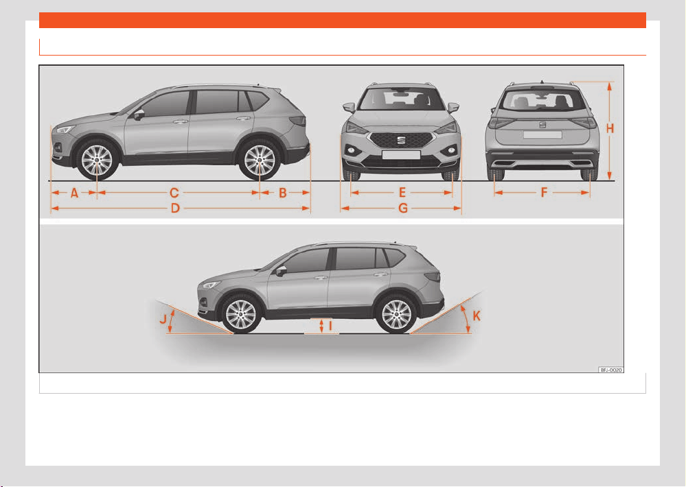
386
Technical data
Dimensions.
Fig.259 Dimensions.

Technical data
387
Indications about the technical data
›››Fig.259
TARRACO
A Front projection (mm) 926
B Rear projection (mm) 1,019
C Wheelbase (mm) 2,790
D Length (mm) 4,735
E Front
a)
tr
ack (mm) 1,585
F Back
a)
track (mm) 1,585
G Width (mm) 1,585
H Height at kerb weight (mm) 1,658
b)
1,674
c)
I Ground clearance between the axles (mm) 192
J Front projection angle limited by the bumper maximum 19.1°
K Rear projection angle limited by the bumper maximum 21.4°
Turning radius (m) 11.9
a)
This data will change depending on the type of wheel rim. Values for wheel 215/65 R17 ET38.
b)
Distance to the roof.
c)
Dimension to the roof bars.

388
Technical data

Index
389
Index
Numbers and Symbol
s
4Drive . . . . . . . . . . . . . . . . . . . . . . . . . . . . . . . . . . . . . . . . 148
12-volt battery . . . . . . . . . . . . . . . . . . . . . . . . . . . . . . . . 341
assisted start . . . . . . . . . . . . . . . . . . . . . . . . . . . . . . . 318
charge level . . . . . . . . . . . . . . . . . . . . . . . . . . . . . . . . 345
charging . . . . . . . . . . . . . . . . . . . . . . . . . . . . . . . . . . . 343
control lamps . . . . . . . . . . . . . . . . . . . . . . . . . . . . . . 344
disconnect and connect . . . . . . . . . . . . . . . . . . . 343
electrolyte level . . . . . . . . . . . . . . . . . . . . . . . . . . . . 342
energy management . . . . . . . . . . . . . . . . . . . . . . . 345
replacement . . . . . . . . . . . . . . . . . . . . . . . . . . . . . . . 343
A
ACC . . . . . . . . . . . . . . . . . . . . . . . . . . . . . . . . . . . . . . . . . . 185
Access aid for the third row . . . . . . . . . . . . . . . . . . . . 116
Accessories . . . . . . . . . . . . . . . . . . . . . . . . . . . . . . . . . . . 372
Activating SEAT CONNECT . . . . . . . . . . . . . . . . . . . 243
Adapting the playback volume . . . . . . . . . . . . . . . 261
Adaptive Cruise Control . . . . . . . . . . . . . . . . . . . . . . 185
control and warning lamp . . . . . . . . . . . . . . . . . . 190
malfunction . . . . . . . . . . . . . . . . . . . . . . . . . . . . . . . . 190
operation . . . . . . . . . . . . . . . . . . . . . . . . . . . . . . . . . . . 187
special driving situations . . . . . . . . . . . . . . . . . . . . 188
status display . . . . . . . . . . . . . . . . . . . . . . . . . . . . . . . 187
System limitations . . . . . . . . . . . . . . . . . . . . . . . . . . 189
AdBlue
control and warning lamps . . . . . . . . . . . . . . . . . 313
information . . . . . . . . . . . . . . . . . . . . . . . . . . . . . . . . . . 311
loading . . . . . . . . . . . . . . . . . . . . . . . . . . . . . . . . . . . . . 312
minimum filling capacity . . . . . . . . . . . . . . . . . . . . 311
specification . . . . . . . . . . . . . . . . . . . . . . . . . . . . . . . . 312
tank capacity . . . . . . . . . . . . . . . . . . . . . . . . . . . . . . . 311
Adjust
f
old down the front passenger’s backrest . . . 108
front seats . . . . . . . . . . . . . . . . . . . . . . . . . . . . . . . . . . 107
headrest . . . . . . . . . . . . . . . . . . . . . . . . . . . . . . . . . . . . 112
lights . . . . . . . . . . . . . . . . . . . . . . . . . . . . . . . . . . . . . . . . 123
rear seat . . . . . . . . . . . . . . . . . . . . . . . . . . . . . . . . . . . . 110
seat with memory . . . . . . . . . . . . . . . . . . . . . . . . . . . 114
seats . . . . . . . . . . . . . . . . . . . . . . . . . . . . . . . . . . . . . . . . 39
time and date . . . . . . . . . . . . . . . . . . . . . . . . . . . . . . . 30
Adjusting the seat belt . . . . . . . . . . . . . . . . . . . . . . . . . 45
Air conditioning . . . . . . . . . . . . . . . . . . . . . . . . . . . . . . . . 131
air recirculation . . . . . . . . . . . . . . . . . . . . . . . . . . . . . 136
controls . . . . . . . . . . . . . . . . . . . . . . . . . . . . . . . . . . . . . 133
Infotainment system settings . . . . . . . . . . . . . . . . 136
manual air conditioning . . . . . . . . . . . . . . . . . . . . . 135
troubleshooting . . . . . . . . . . . . . . . . . . . . . . . . . . . . 140
Air recirculation . . . . . . . . . . . . . . . . . . . . . . . . . . . . . . . 136
Airbag system . . . . . . . . . . . . . . . . . . . . . . . . . . . . . . . . . 49
activation . . . . . . . . . . . . . . . . . . . . . . . . . . . . . . . . . . . 50
control lamp . . . . . . . . . . . . . . . . . . . . . . . . . . . . . . . . . 51
deactivation of the front airbag . . . . . . . . . . . . . . 52
description . . . . . . . . . . . . . . . . . . . . . . . . . . . . . . . . . . 49
front airbags . . . . . . . . . . . . . . . . . . . . . . . . . . . . . . . . . 51
how it works . . . . . . . . . . . . . . . . . . . . . . . . . . . . . . . . . 50
Airbags . . . . . . . . . . . . . . . . . . . . . . . . . . . . . . . . . . . . . . . . 49
activating and deactivating . . . . . . . . . . . . . . . . . 52
description . . . . . . . . . . . . . . . . . . . . . . . . . . . . . . . . . . 49
for the head . . . . . . . . . . . . . . . . . . . . . . . . . . . . . . . . . 54
for the knees . . . . . . . . . . . . . . . . . . . . . . . . . . . . . . . . . 55
front . . . . . . . . . . . . . . . . . . . . . . . . . . . . . . . . . . . . . . . . . 51
side . . . . . . . . . . . . . . . . . . . . . . . . . . . . . . . . . . . . . . . . . . 53
Android Auto™
disconnecting . . . . . . . . . . . . . . . . . . . . . . . . . . . . . . 251
establish connection . . . . . . . . . . . . . . . . . . . . . . . . 251
menu . . . . . . . . . . . . . . . . . . . . . . . . . . . . . . . . . . . . . . . 251
requirements . . . . . . . . . . . . . . . . . . . . . . . . . . . . . . . . 251
special char
acteristics . . . . . . . . . . . . . . . . . . . . . . 251
Anti-lock brake system . . . . . . . . . . . . . . . . . . . . . . . . 174
Anti-puncture . . . . . . . . . . . . . . . . . . . . . . . . . . . . . . . . 360
Anti-puncture kit . . . . . . . . . . . . . . . . . . . . . . . . . . . . . 360
check after 10 minutes . . . . . . . . . . . . . . . . . . . . . 363
components . . . . . . . . . . . . . . . . . . . . . . . . . . . . . . . . 361
inflating the tyre . . . . . . . . . . . . . . . . . . . . . . . . . . . . 362
sealing the tyre . . . . . . . . . . . . . . . . . . . . . . . . . . . . . 362
Anti-puncture set . . . . . . . . . . . . . . . . . . . . . . . . . . . . . 360
Anti-theft alarm . . . . . . . . . . . . . . . . . . . . . . . . . . . . . . . 90
interior monitoring and anti-tow system . . . . . . 91
trailer . . . . . . . . . . . . . . . . . . . . . . . . . . . . . . . . . . . . . . 299
Anti-theft alarm system . . . . . . . . . . . . . . . . . . . . . . . . 90
Anti-trap function
glass roof sun blind . . . . . . . . . . . . . . . . . . . . . . . . . 103
sunroof . . . . . . . . . . . . . . . . . . . . . . . . . . . . . . . . . . . . . 102
windows . . . . . . . . . . . . . . . . . . . . . . . . . . . . . . . . . . . . 100
Antifreeze . . . . . . . . . . . . . . . . . . . . . . . . . . . . . . . . . . . . . 332
Apple CarPlay
disconnecting . . . . . . . . . . . . . . . . . . . . . . . . . . . . . . 250
establish connection . . . . . . . . . . . . . . . . . . . . . . . 250
menu . . . . . . . . . . . . . . . . . . . . . . . . . . . . . . . . . . . . . . . 250
requirements . . . . . . . . . . . . . . . . . . . . . . . . . . . . . . . 250
special characteristics . . . . . . . . . . . . . . . . . . . . . 250
Applications (apps) . . . . . . . . . . . . . . . . . . . . . . . . . . 250
Approved spare parts . . . . . . . . . . . . . . . . . . . . . . . . 366
Area View system . . . . . . . . . . . . . . . . . . . . . . . . . . . . . 182
Aspects to think about before starting the vehicle
. . . . . . . . . . . . . . . . . . . . . . . . . . . . . . . . . . . . . . . . . . . . . . . . . 38
Assistance systems
adaptive cruise control . . . . . . . . . . . . . . . . . . . . . 185
area view system . . . . . . . . . . . . . . . . . . . . . . . . . . . 182
Auto-Hold function . . . . . . . . . . . . . . . . . . . . . . . . . 208
connecting . . . . . . . . . . . . . . . . . . . . . . . . . . . . . . . . . 178
cruise control . . . . . . . . . . . . . . . . . . . . . . . . . . . . . . . 182

390
Index
driver alert system . . . . . . . . . . . . . . . . . . . . . . . . . . . 25
driving assist (T
ravel Assist) . . . . . . . . . . . . . . . . . 198
Emergency Assist . . . . . . . . . . . . . . . . . . . . . . . . . . . 201
emergency braking (Front Assist) . . . . . . . . . . . 193
front camera . . . . . . . . . . . . . . . . . . . . . . . . . . . . . . . 180
front radar . . . . . . . . . . . . . . . . . . . . . . . . . . . . . . . . . . 179
general notes . . . . . . . . . . . . . . . . . . . . . . . . . . . . . . . 178
Hill Hold Control (HHC) . . . . . . . . . . . . . . . . . . . . . 168
lane departure warning (Side Assist) . . . . . . . 202
parking aid Plus . . . . . . . . . . . . . . . . . . . . . . . . . . . . 210
peripheral view system (Top View Camera) . 226
PreCrash system . . . . . . . . . . . . . . . . . . . . . . . . . . . . 47
predictive speed adjustment . . . . . . . . . . . . . . . . 191
rear parking aid . . . . . . . . . . . . . . . . . . . . . . . . . . . . . 214
rear radar . . . . . . . . . . . . . . . . . . . . . . . . . . . . . . . . . . 180
road signs detection system . . . . . . . . . . . . . . . . . 27
safety advice . . . . . . . . . . . . . . . . . . . . . . . . . . . . . . . 178
speed limiter . . . . . . . . . . . . . . . . . . . . . . . . . . . . . . . . 184
switching o . . . . . . . . . . . . . . . . . . . . . . . . . . . . . . . . 178
system limits . . . . . . . . . . . . . . . . . . . . . . . . . . . . . . . . 178
Trailer assist . . . . . . . . . . . . . . . . . . . . . . . . . . . . . . . . 230
tyre pressure monitor indicator . . . . . . . . . . . . . 359
tyre pressure monitoring . . . . . . . . . . . . . . . . . . . 360
ultrasound sensors . . . . . . . . . . . . . . . . . . . . . . . . . . 181
Assisted start . . . . . . . . . . . . . . . . . . . . . . . . . . . . . . . . . 318
Audible warning
lights . . . . . . . . . . . . . . . . . . . . . . . . . . . . . . . . . . . . . . . . 119
unbuckled seat belt . . . . . . . . . . . . . . . . . . . . . . . . . 42
Audio warning signals
warning and control lamps . . . . . . . . . . . . . . . . . . . 11
Auto Lock (central locking) . . . . . . . . . . . . . . . . . . . . . 87
Auto Unlock . . . . . . . . . . . . . . . . . . . . . . . . . . . . . . . . . . . . 87
Auto-Hold . . . . . . . . . . . . . . . . . . . . . . . . . . . . . . . . . . . . 208
Auto-Hold function . . . . . . . . . . . . . . . . . . . . . . . . . . . 208
Automatic car wash . . . . . . . . . . . . . . . . . . . . . . . . . . 367
disconnecting the Auto-Hold function . . . . . . 208
Automatic dipped beam headlight control . . . . 118
Aut
omatic gearbox
control lamp . . . . . . . . . . . . . . . . . . . . . . . . . . . . . . . . 161
downhill assistant . . . . . . . . . . . . . . . . . . . . . . . . . . 168
driving tips . . . . . . . . . . . . . . . . . . . . . . . . . . . . . . . . . . 164
launch-control program . . . . . . . . . . . . . . . . . . . . 165
selector lever positions . . . . . . . . . . . . . . . . . . . . . . 161
steering wheel with shift paddles . . . . . . . . . . . 163
tiptronic . . . . . . . . . . . . . . . . . . . . . . . . . . . . . . . . . . . . 163
Auxiliary heating
activate . . . . . . . . . . . . . . . . . . . . . . . . . . . . . . . . . . . . 144
connecting . . . . . . . . . . . . . . . . . . . . . . . . . . . . . . . . . . 141
electricity consumers . . . . . . . . . . . . . . . . . . . . . . . 140
programming . . . . . . . . . . . . . . . . . . . . . . . . . . . . . . . 144
radio-operated remote control . . . . . . . . . . . . . 142
special characteristics . . . . . . . . . . . . . . . . . . . . . 140
switching o . . . . . . . . . . . . . . . . . . . . . . . . . . . . . . . . 141
Average fuel consumption . . . . . . . . . . . . . . . . . . . . . 16
B
Backrest of the rear seat
folding . . . . . . . . . . . . . . . . . . . . . . . . . . . . . . . . . . . . . . . 111
raise . . . . . . . . . . . . . . . . . . . . . . . . . . . . . . . . . . . . . . . . . 111
Bag hooks . . . . . . . . . . . . . . . . . . . . . . . . . . . . . . . 238, 294
Battery . . . . . . . . . . . . . . . . . . . . . . . . . . . . . . . . . . . . . . . . 83
Before starting the vehicle . . . . . . . . . . . . . . . . . . . . . 38
Belt force limiter . . . . . . . . . . . . . . . . . . . . . . . . . . . . . . . 46
Belt tightening . . . . . . . . . . . . . . . . . . . . . . . . . . . . . . . . . 46
Bicycle carrier
fitting onto the coverable tow hook . . . . . . . . . 305
max. load rating . . . . . . . . . . . . . . . . . . . . . . . . . . . . 305
Biodiesel . . . . . . . . . . . . . . . . . . . . . . . . . . . . . . . . . . . . . . 311
Blown bulbs
change a bulb . . . . . . . . . . . . . . . . . . . . . . . . . . . . . . 328
Bonnet
opening and closing . . . . . . . . . . . . . . . . . . . . . . . . 331
Brake fluid . . . . . . . . . . . . . . . . . . . . . . . . . . . . . . . . . . . .
335
Brakes . . . . . . . . . . . . . . . . . . . . . . . . . . . . . . . . . . . . . . . . . 172
brake fluid . . . . . . . . . . . . . . . . . . . . . . . . . . . . . . . . . . 335
brake servo . . . . . . . . . . . . . . . . . . . . . . . . . . . . . . . . . 172
braking assistant . . . . . . . . . . . . . . . . . . . . . . . . . . . . 174
electronic parking brake . . . . . . . . . . . . . . . . . . . 207
new brake pads . . . . . . . . . . . . . . . . . . . . . . . . . . . . . 172
Braking assistant . . . . . . . . . . . . . . . . . . . . . . . . . . . . . . 174
Braking system
warning lamp . . . . . . . . . . . . . . . . . . . . . . . . . . . . . . . 173
Brands . . . . . . . . . . . . . . . . . . . . . . . . . . . . . . . . . . . . . . . . 262
C
Camera
cleaning the vehicle . . . . . . . . . . . . . . . . . . . . . . . . . 28
Catalytic converter . . . . . . . . . . . . . . . . . . . . . . . . . . . 314
Central armrests . . . . . . . . . . . . . . . . . . . . . . . . . . . . . . 115
Central locking . . . . . . . . . . . . . . . . . . . . . . . . . . . . . . . . 86
anti-theft alarm . . . . . . . . . . . . . . . . . . . . . . . . . . . . . 90
auto-locking due to involuntary opening . . . . . 87
central locking switch . . . . . . . . . . . . . . . . . . . . . . . 88
emergency lock . . . . . . . . . . . . . . . . . . . . . . . . . . . . . 93
Keyless Access system . . . . . . . . . . . . . . . . . . . . . . 84
remote control key . . . . . . . . . . . . . . . . . . . . . . . . . . 88
Cetane index (diesel fuel) . . . . . . . . . . . . . . . . . . . . . 311
Change a bulb . . . . . . . . . . . . . . . . . . . . . . . . . . . . . . . 328
Change the wiper blades . . . . . . . . . . . . . . . . . . . . . 316
Changing a wheel . . . . . . . . . . . . . . . . . . . . . . . . . . . . 353
raise the vehicle . . . . . . . . . . . . . . . . . . . . . . . . . . . . 357
subsequent work . . . . . . . . . . . . . . . . . . . . . . . . . . . 358
wheel nuts . . . . . . . . . . . . . . . . . . . . . . . . . . . . . . . . . 356
Changing parts . . . . . . . . . . . . . . . . . . . . . . . . . . . . . . . 372
Changing the battery
of the vehicle key . . . . . . . . . . . . . . . . . . . . . . . . . . . . 83

Index
391
Charging cable
f
or charging stations (AC) . . . . . . . . . . . . . . . . . . . 79
for sockets . . . . . . . . . . . . . . . . . . . . . . . . . . . . . . . . . . 80
Charging socket . . . . . . . . . . . . . . . . . . . . . . . . . . . . . . . 73
Charging the high-voltage battery
charging cable . . . . . . . . . . . . . . . . . . . . . . . . . . . . . . 79
charging modes . . . . . . . . . . . . . . . . . . . . . . . . . . . . . . 71
charging process display . . . . . . . . . . . . . . . . . . . . 74
emergency unlocking . . . . . . . . . . . . . . . . . . . . . . . . 76
Infotainment system settings . . . . . . . . . . . . . . . . . 77
programmed charging . . . . . . . . . . . . . . . . . . . . . . . 77
socket (AC) . . . . . . . . . . . . . . . . . . . . . . . . . . . . . . . . . . 73
troubleshooting . . . . . . . . . . . . . . . . . . . . . . . . . . . . . . 75
Check lists
requirements for Android Auto™ . . . . . . . . . . . . . 251
requirements for Apple CarPlay . . . . . . . . . . . . 250
requirements for MirrorLink® . . . . . . . . . . . . . . . . 252
reverse assist (Rear View) . . . . . . . . . . . . . . . . . . . 223
Child lock
electric windows . . . . . . . . . . . . . . . . . . . . . . . . . . . . 98
Child seats
attachment systems . . . . . . . . . . . . . . . . . . . . . . . . . 58
group classification . . . . . . . . . . . . . . . . . . . . . . . . . 56
i-Size . . . . . . . . . . . . . . . . . . . . . . . . . . . . . . . . . . . . . . . . 59
ISOFIX . . . . . . . . . . . . . . . . . . . . . . . . . . . . . . . . . . . . . . . 59
safety instructions . . . . . . . . . . . . . . . . . . . . . . . . . . . 57
securing with the seat belt . . . . . . . . . . . . . . . . . . . 63
Top Tether system . . . . . . . . . . . . . . . . . . . . . . . 62, 63
Cleaning
high pressure cleaning equipment . . . . . . . . . . 367
special care . . . . . . . . . . . . . . . . . . . . . . . . . . . . . . . . 371
vehicle exterior . . . . . . . . . . . . . . . . . . . . . . . . . . . . . 368
vehicle interior . . . . . . . . . . . . . . . . . . . . . . . . . . . . . 370
washing the vehicle . . . . . . . . . . . . . . . . . . . . . . . . 367
Climate control
r
ear controls . . . . . . . . . . . . . . . . . . . . . . . . . . . . . . . . 136
setting the temperature . . . . . . . . . . . . . . . . . . . . . 136
windscreen heating . . . . . . . . . . . . . . . . . . . . . . . . . 139
Clocks
set the time . . . . . . . . . . . . . . . . . . . . . . . . . . . . . . . . . . 30
Closing . . . . . . . . . . . . . . . . . . . . . . . . . . . . . . . . . . . . . . . . . 86
bonnet . . . . . . . . . . . . . . . . . . . . . . . . . . . . . . . . . . . . . . 331
rear lid . . . . . . . . . . . . . . . . . . . . . . . . . . . . . . . . . . . . . . . . 95
sunroof . . . . . . . . . . . . . . . . . . . . . . . . . . . . . . . . . . . . . . . 101
windows . . . . . . . . . . . . . . . . . . . . . . . . . . . . . . . . . . . . . . 98
Clutch (lamp) . . . . . . . . . . . . . . . . . . . . . . . . . . . . . . . . . 167
Coming Home . . . . . . . . . . . . . . . . . . . . . . . . . . . . . . . . 122
Connectivity
WLAN access point . . . . . . . . . . . . . . . . . . . . . . . . . 247
Control and warning lamps
12-volt battery . . . . . . . . . . . . . . . . . . . . . . . . . . . . . 344
ACC . . . . . . . . . . . . . . . . . . . . . . . . . . . . . . . . . . . . . . . . 190
adaptive cruise control . . . . . . . . . . . . . . . . . . . . . 187
AdBlue . . . . . . . . . . . . . . . . . . . . . . . . . . . . . . . . . . . . . . 313
air conditioning . . . . . . . . . . . . . . . . . . . . . . . . . . . . . 140
airbag system . . . . . . . . . . . . . . . . . . . . . . . . . . . . . . . . 51
airbags . . . . . . . . . . . . . . . . . . . . . . . . . . . . . . . . . . . . . . 52
anti-lock brake system ABS . . . . . . . . . . . . . . . . . 176
automatic gearbox . . . . . . . . . . . . . . . . . . . . . . . . . . 161
braking system . . . . . . . . . . . . . . . . . . . . . . . . . . . . . . 173
cruise control . . . . . . . . . . . . . . . . . . . . . . . . . . . . . . . 184
cruise control (GRA) . . . . . . . . . . . . . . . . . . . . . . . . 182
drive system . . . . . . . . . . . . . . . . . . . . . . . . . . . . . . . . 156
E-MODE operating mode . . . . . . . . . . . . . . . . . . . 158
electromechanical steering . . . . . . . . . . . . . . . . 169
emissions control . . . . . . . . . . . . . . . . . . . . . . . . . . . 315
engine coolant . . . . . . . . . . . . . . . . . . . . . . . . . . . . . . 20
engine management . . . . . . . . . . . . . . . . . . . . . . . 315
engine oil . . . . . . . . . . . . . . . . . . . . . . . . . . . . . . . . . . 340
ESC . . . . . . . . . . . . . . . . . . . . . . . . . . . . . . . . . . . . . . . . 176
ESC in Sport mode . . . . . . . . . . . . . . . . . . . . . . . . . . 175
ESC o . . . . . . . . . . . . . . . . . . . . . . . . . . . . . . . . . . . . .
175
fuel reserve . . . . . . . . . . . . . . . . . . . . . . . . . . . . . . . . . . 18
high-voltage battery . . . . . . . . . . . . . . . . . . . . . . . . . 75
high-voltage system . . . . . . . . . . . . . . . . . . . . . . . . . 75
hill descent control . . . . . . . . . . . . . . . . . . . . . . . . . 168
Lane Assist . . . . . . . . . . . . . . . . . . . . . . . . . . . . . 197, 198
lane departure warning (Side Assist) . . . . . . . 203
lights . . . . . . . . . . . . . . . . . . . . . . . . . . . . . . . . . . . . . . . . 118
parking brake . . . . . . . . . . . . . . . . . . . . . . . . . . . . . . 208
particulate filter . . . . . . . . . . . . . . . . . . . . . . . . 314, 315
press on the brake . . . . . . . . . . . . . . . . . . . . . . . . . . 185
refuelling . . . . . . . . . . . . . . . . . . . . . . . . . . . . . . . 18, 309
remote control (independent heating) . . . . . . 142
seat belt . . . . . . . . . . . . . . . . . . . . . . . . . . . . . . . . . . . . . 42
speed limiter . . . . . . . . . . . . . . . . . . . . . . . . . . . . . . . . 185
Start-Stop . . . . . . . . . . . . . . . . . . . . . . . . . . . . . . . . . . 158
steering column . . . . . . . . . . . . . . . . . . . . . . . . . . . . 169
TCS . . . . . . . . . . . . . . . . . . . . . . . . . . . . . . . . . . . . . . . . . 176
tow hook . . . . . . . . . . . . . . . . . . . . . . . . . . . . . . . . . . . 304
tyre pressure monitor system . . . . . . . . . . . . . . . 360
Control lamps
overview . . . . . . . . . . . . . . . . . . . . . . . . . . . . . . . . . . . . . . 11
Controls
rear seat . . . . . . . . . . . . . . . . . . . . . . . . . . . . . . . . . . . . 110
Controls on the steering wheel . . . . . . . . . . . . . . . 105
Convenience close function
sunroof . . . . . . . . . . . . . . . . . . . . . . . . . . . . . . . . . . . . . 102
Convenience open function
sunroof . . . . . . . . . . . . . . . . . . . . . . . . . . . . . . . . . . . . . 102
Cooling . . . . . . . . . . . . . . . . . . . . . . . . . . . . . . . . . . . . . . . 131
Cooling system
check the coolant . . . . . . . . . . . . . . . . . . . . . . . . . . 334
refilling coolant . . . . . . . . . . . . . . . . . . . . . . . . . . . . 334
Copyright . . . . . . . . . . . . . . . . . . . . . . . . . . . . . . . . . . . . 262
Cornering light . . . . . . . . . . . . . . . . . . . . . . . . . . . . . . . . 119

392
Index
Correct position . . . . . . . . . . . . . . . . . . . . . . . . . . . . . . . 39
driv
er . . . . . . . . . . . . . . . . . . . . . . . . . . . . . . . . . . . . . . . . 39
passenger . . . . . . . . . . . . . . . . . . . . . . . . . . . . . . . . . . . 40
Cruise control . . . . . . . . . . . . . . . . . . . . . . . . . . . . . . . . . 182
Cruise control system . . . . . . . . . . . . . . . . . . . . . . . . . 182
control lamps . . . . . . . . . . . . . . . . . . . . . . . . . . . . . . . 184
operating . . . . . . . . . . . . . . . . . . . . . . . . . . . . . . . . . . . 183
Current documentation attached . . . . . . . . . . . . 254
D
Dangers of not using the seat belt . . . . . . . . . . . . . 43
Data label . . . . . . . . . . . . . . . . . . . . . . . . . . . . . . . . . . . . 382
Data transfer . . . . . . . . . . . . . . . . . . . . . . . . . . . . . . . . . 242
Deactivating SEAT CONNECT services . . . . . . . 245
Deactivation of the front airbag . . . . . . . . . . . . . . . . 52
Diesel
refuelling . . . . . . . . . . . . . . . . . . . . . . . . . . . . . . . . . . . . 311
Disposal
seat belt tensioners . . . . . . . . . . . . . . . . . . . . . . . . . . 47
Door cylinder . . . . . . . . . . . . . . . . . . . . . . . . . . . . . . . . . . 92
Door handle . . . . . . . . . . . . . . . . . . . . . . . . . . . . . . . . . . . 92
Door lock . . . . . . . . . . . . . . . . . . . . . . . . . . . . . . . . . . . . . . 92
Doors . . . . . . . . . . . . . . . . . . . . . . . . . . . . . . . . . . . . . . . . . . 92
child lock . . . . . . . . . . . . . . . . . . . . . . . . . . . . . . . . . . . . 94
Downhill assistance function . . . . . . . . . . . . . . . . . . 168
downhill assistant . . . . . . . . . . . . . . . . . . . . . . . . . . . . . 168
Drawers . . . . . . . . . . . . . . . . . . . . . . . . . . . . . . . . . . . . . . 238
Drink holder
bottle holder . . . . . . . . . . . . . . . . . . . . . . . . . . . . . . . 237
front . . . . . . . . . . . . . . . . . . . . . . . . . . . . . . . . . . . . . . . . 237
in the rear central armrest . . . . . . . . . . . . . . . . . . 237
Drive system
control lamps . . . . . . . . . . . . . . . . . . . . . . . . . . . . . . . 156
Driver alert system . . . . . . . . . . . . . . . . . . . . . . . . . . . . . 25
Driving
driving on flooded r
oads . . . . . . . . . . . . . . . . . . . . 148
economical . . . . . . . . . . . . . . . . . . . . . . . . . . . . . . . . . 145
loaded vehicle . . . . . . . . . . . . . . . . . . . . . . . . . . . . . . 147
safe . . . . . . . . . . . . . . . . . . . . . . . . . . . . . . . . . . . . . . . . . 38
trips abroad . . . . . . . . . . . . . . . . . . . . . . . . . . . . 123, 149
with the luggage compartment open . . . . . . . 147
with trailer . . . . . . . . . . . . . . . . . . . . . . . . . . . . . . . . . . 302
Driving Assist (Travel Assist)
see Travel Assist . . . . . . . . . . . . . . . . . . . . . . . . . . . . 198
Driving data . . . . . . . . . . . . . . . . . . . . . . . . . . . . . . . . . . . 23
Driving data indicator . . . . . . . . . . . . . . . . . . . . . . . . . . 23
Driving mode . . . . . . . . . . . . . . . . . . . . . . . . . . . . . . . . . . 172
Driving on flooded roads . . . . . . . . . . . . . . . . . . . . . 148
Driving profile . . . . . . . . . . . . . . . . . . . . . . . . . . . . . . . . . 172
Driving with a loaded vehicle . . . . . . . . . . . . . . . . . . 147
Driving with the luggage compartment open . 147
DSG . . . . . . . . . . . . . . . . . . . . . . . . . . . . . . . . . . . . . . . . . . . 161
Duplicate keys . . . . . . . . . . . . . . . . . . . . . . . . . . . . . . . . . 82
Dust and pollen filter . . . . . . . . . . . . . . . . . . . . . . . . . . 131
Dynamic headlight range control . . . . . . . . . . . . . 123
E
e-Call . . . . . . . . . . . . . . . . . . . . . . . . . . . . . . . . . . . . . . . . . 66
E-Mode . . . . . . . . . . . . . . . . . . . . . . . . . . . . . . . . . . . . . . . 156
E-MODE operating mode
control lamps . . . . . . . . . . . . . . . . . . . . . . . . . . . . . . . 158
E10
see Ethanol (fuel) . . . . . . . . . . . . . . . . . . . . . . . . . . . 311
Easy Open
special characteristics . . . . . . . . . . . . . . . . . . . . . . . 97
Eco-driving notes . . . . . . . . . . . . . . . . . . . . . . . . . . . . . . 29
Electric devices . . . . . . . . . . . . . . . . . . . . . . . . . . . . . . 239
Electric windows . . . . . . . . . . . . . . . . . . . . . . . . . . . . . . . 98
Electrolyte . . . . . . . . . . . . . . . . . . . . . . . . . . . . . . . . . . . . 342
Electronic dierential lock . . . . . . . . . . . . . . . . . . . . . 174
Electronic immobilizer . . . . . . . . . . . . . . . . . . . . . . . . . 153
El
ectronic parking brake . . . . . . . . . . . . . . . . . . . . . . 207
control lamps . . . . . . . . . . . . . . . . . . . . . . . . . . . . . . 208
Electronic Stability Control (ESC) . . . . . . . . . . . . . 174
Emergencies . . . . . . . . . . . . . . . . . . . . . . . . . . . . . . . . . . 66
anti-puncture kit . . . . . . . . . . . . . . . . . . . . . . . . . . . 360
changing a wheel . . . . . . . . . . . . . . . . . . . . . . . . . . 353
changing the battery . . . . . . . . . . . . . . . . . . . . . . . 343
emergency vehicle towing . . . . . . . . . . . . . . . . . 320
hazard warning lights . . . . . . . . . . . . . . . . . . . . . . . . 65
jump leads . . . . . . . . . . . . . . . . . . . . . . . . . . . . . . . . . . 318
replace a blown fuse . . . . . . . . . . . . . . . . . . . . . . . 326
vehicle tool kit . . . . . . . . . . . . . . . . . . . . . . . . . . . . . . 316
Emergency Assist . . . . . . . . . . . . . . . . . . . . . . . . . . . . . 201
connecting and disconnecting . . . . . . . . . . . . . 201
problems and solutions . . . . . . . . . . . . . . . . . . . . 202
see Emergency Assist . . . . . . . . . . . . . . . . . . . . . . . 201
status display . . . . . . . . . . . . . . . . . . . . . . . . . . . . . . . 201
Emergency braking assist system . . . . . . . . . . . . . 179
activating and deactivating . . . . . . . . . . . . . . . . 195
status display . . . . . . . . . . . . . . . . . . . . . . . . . . . . . . . 193
system limitations . . . . . . . . . . . . . . . . . . . . . . . . . . 194
temporarily deactivating . . . . . . . . . . . . . . . . . . . 196
warnings . . . . . . . . . . . . . . . . . . . . . . . . . . . . . . . . . . . 193
Emergency braking warning . . . . . . . . . . . . . . . . . . . 65
Emergency call . . . . . . . . . . . . . . . . . . . . . . . . . . . . . . . . 66
Emergency call service . . . . . . . . . . . . . . . . . . . . . . . . 66
Emergency locking of the front passenger door
. . . . . . . . . . . . . . . . . . . . . . . . . . . . . . . . . . . . . . . . . . . . . . . . . 93
Emergency opening
driver's door . . . . . . . . . . . . . . . . . . . . . . . . . . . . . . . . . 92
rear lid . . . . . . . . . . . . . . . . . . . . . . . . . . . . . . . . . . . . . . 98
Emergency operation
front passenger door . . . . . . . . . . . . . . . . . . . . . . . . 93

Index
393
Emissions control system
AdBlue
. . . . . . . . . . . . . . . . . . . . . . . . . . . . . . . . . . . . . . 311
catalytic converter . . . . . . . . . . . . . . . . . . . . . . . . . 314
control lamp . . . . . . . . . . . . . . . . . . . . . . . . . . . . . . . . 315
particulate filter . . . . . . . . . . . . . . . . . . . . . . . . . . . . 314
Energy management . . . . . . . . . . . . . . . . . . . . . . . . . 345
Engine
noise . . . . . . . . . . . . . . . . . . . . . . . . . . . . . . . . . . . . . . . . 151
running in . . . . . . . . . . . . . . . . . . . . . . . . . . . . . . . . . . . 148
start (driver instructions with the mechanical
contact) . . . . . . . . . . . . . . . . . . . . . . . . . . . . . . . . . . . . 154
Start-Stop system . . . . . . . . . . . . . . . . . . . . . . . . . . 158
Engine and ignition
emergency start . . . . . . . . . . . . . . . . . . . . . . . . . . . . 154
preheat the engine . . . . . . . . . . . . . . . . . . . . . . . . . . 151
starting the engine . . . . . . . . . . . . . . . . . . . . . . . . . . 151
starting the engine with Press & Drive . . . . . . . 151
switching o the engine . . . . . . . . . . . . . . . . . . . . . 152
Engine compartment
battery . . . . . . . . . . . . . . . . . . . . . . . . . . . . . . . . . . . . . 341
engine oil . . . . . . . . . . . . . . . . . . . . . . . . . . . . . . . . . . 339
opening and closing . . . . . . . . . . . . . . . . . . . . . . . . 331
safety instructions . . . . . . . . . . . . . . . . . . . . . . . . . . 329
Engine coolant . . . . . . . . . . . . . . . . . . . . . . . . . . . . . . . 332
check the level . . . . . . . . . . . . . . . . . . . . . . . . . . . . . 334
exterior . . . . . . . . . . . . . . . . . . . . . . . . . . . . . . . . . . . . . . 22
specifications . . . . . . . . . . . . . . . . . . . . . . . . . . . . . . 332
tank (hybrid vehicles) . . . . . . . . . . . . . . . . . . . . . . . 333
temperature indicator . . . . . . . . . . . . . . . . . . . . . . . . 20
warning lamp . . . . . . . . . . . . . . . . . . . . . . . . . . . . . . . . 20
Engine failure
control lamp . . . . . . . . . . . . . . . . . . . . . . . . . . . . . . . . 315
Engine management . . . . . . . . . . . . . . . . . . . . . . . . . . 313
control lamp . . . . . . . . . . . . . . . . . . . . . . . . . . . . . . . . 315
Engine oil
change
. . . . . . . . . . . . . . . . . . . . . . . . . . . . . . . 337, 340
check the oil level . . . . . . . . . . . . . . . . . . . . . . . . . . 339
consumption . . . . . . . . . . . . . . . . . . . . . . . . . . . . . . . 339
dipstick . . . . . . . . . . . . . . . . . . . . . . . . . . . . . . . . . . . . 339
inspection service . . . . . . . . . . . . . . . . . . . . . . . . . . 337
maintenance frequencies . . . . . . . . . . . . . . . . . . 337
refill . . . . . . . . . . . . . . . . . . . . . . . . . . . . . . . . . . . . . . . . 339
specifications . . . . . . . . . . . . . . . . . . . . . . . . . . . . . . 337
Engine oil pressure
control lamp . . . . . . . . . . . . . . . . . . . . . . . . . . . . . . . 340
Engine specifications . . . . . . . . . . . . . . . . . . . . . . . . . 384
Environment
ecological driving . . . . . . . . . . . . . . . . . . . . . . . . . . 145
environmental compatibility . . . . . . . . . . . . . . . . 376
recycling of electrical appliances . . . . . . . . . . 376
refuelling . . . . . . . . . . . . . . . . . . . . . . . . . . . . . . . . . . . 308
Environmental tip
refuelling . . . . . . . . . . . . . . . . . . . . . . . . . . . . . . . . . . . 308
ESC
connecting and disconnecting . . . . . . . . . . . . . . 175
electronic stability control (ESC) . . . . . . . . . . . . 174
Sport mode . . . . . . . . . . . . . . . . . . . . . . . . . . . . . . . . . 175
Ethanol (fuel) . . . . . . . . . . . . . . . . . . . . . . . . . . . . . . . . . . 311
Event Data Recorder . . . . . . . . . . . . . . . . . . . . . . . . . 375
Exhaust gases . . . . . . . . . . . . . . . . . . . . . . . . . . . . . . . . 313
Exiting a parking space
with the parking assist system . . . . . . . . . . . . . . 222
Exterior lighting
change a bulb . . . . . . . . . . . . . . . . . . . . . . . . . . . . . . 328
Exterior mirrors
driving with a trailer . . . . . . . . . . . . . . . . . . . . . . . . 298
folding . . . . . . . . . . . . . . . . . . . . . . . . . . . . . . . . . . . . . . 129
heated . . . . . . . . . . . . . . . . . . . . . . . . . . . . . . . . . . . . . . 129
settings . . . . . . . . . . . . . . . . . . . . . . . . . . . . . . . . . . . . . 129
External antenna . . . . . . . . . . . . . . . . . . . . . . . . . . . . . 373
External audio sources
adapting the pl
ayback volume . . . . . . . . . . . . . 261
F
Fabrics: clean . . . . . . . . . . . . . . . . . . . . . . . . . . . . . . . . 370
Factors that have a negative influence on safe
driving . . . . . . . . . . . . . . . . . . . . . . . . . . . . . . . . . . . . . . . . . 38
Fastening rings . . . . . . . . . . . . . . . . . . . . . . . . . . . . . . . 293
Filling capacities
AdBlue tank . . . . . . . . . . . . . . . . . . . . . . . . . . . . . . . . . 311
window washer water . . . . . . . . . . . . . . . . . . . . . . 336
Filling the tank . . . . . . . . . . . . . . . . . . . . . . . . . . . . . . . . 309
Fire . . . . . . . . . . . . . . . . . . . . . . . . . . . . . . . . . . . . . . . . . . . . 66
Four-wheel drive . . . . . . . . . . . . . . . . . . . . . . . . . . . . . . 148
Frequency bands . . . . . . . . . . . . . . . . . . . . . . . . . . . . . 267
Front bonnet . . . . . . . . . . . . . . . . . . . . . . . . . . . . . . . . . 329
Front camera . . . . . . . . . . . . . . . . . . . . . . . . . . . . . . . . . 180
Front compartment
brake fluid . . . . . . . . . . . . . . . . . . . . . . . . . . . . . . . . . . 335
coolant . . . . . . . . . . . . . . . . . . . . . . . . . . . . . . . . 332, 334
windscreen washer reservoir . . . . . . . . . . . . . . . 336
Front passenger front airbag
control lamp . . . . . . . . . . . . . . . . . . . . . . . . . . . . . . . . . 51
Fuel
diesel . . . . . . . . . . . . . . . . . . . . . . . . . . . . . . . . . . . . . . . 311
ethanol . . . . . . . . . . . . . . . . . . . . . . . . . . . . . . . . . . . . . 311
fuel gauge . . . . . . . . . . . . . . . . . . . . . . . . . . . . . . . . . . . 18
identification . . . . . . . . . . . . . . . . . . . . . . . . . . . . . . . 310
petrol . . . . . . . . . . . . . . . . . . . . . . . . . . . . . . . . . . . . . . . 310
refuelling . . . . . . . . . . . . . . . . . . . . . . . . . . . . . . . . . . . 309
saving . . . . . . . . . . . . . . . . . . . . . . . . . . . . . . . . . . . . . . 145
Fuel consumption
inertia disconnection . . . . . . . . . . . . . . . . . . . . . . . 145
why does consumption increase? . . . . . . . . . . 315
Fuel gauge . . . . . . . . . . . . . . . . . . . . . . . . . . . . . . . . . . . . . 18
control lamp . . . . . . . . . . . . . . . . . . . . . . . . . . . . . . . . . 18

394
Index
Fuel tank cap
opening and cl
osing . . . . . . . . . . . . . . . . . . . . . . . 309
Fuel tank flap
opening and closing . . . . . . . . . . . . . . . . . . . . . . . 309
Full Link . . . . . . . . . . . . . . . . . . . . . . . . . . . . . . . . . . . . . . . 248
applications . . . . . . . . . . . . . . . . . . . . . . . . . . . . . . . . 250
settings . . . . . . . . . . . . . . . . . . . . . . . . . . . . . . . . . . . . 250
symbols . . . . . . . . . . . . . . . . . . . . . . . . . . . . . . . . . . . . 250
Full-LED headlights . . . . . . . . . . . . . . . . . . . . . . . . . . . 328
Fuses . . . . . . . . . . . . . . . . . . . . . . . . . . . . . . . . . . . . . . . . . 324
colour coded . . . . . . . . . . . . . . . . . . . . . . . . . . . . . . . 325
fuse box . . . . . . . . . . . . . . . . . . . . . . . . . . . . . . . 325, 326
preparations for replacing fuses . . . . . . . . . . . . 326
recognise blown fuses . . . . . . . . . . . . . . . . . . . . . . 326
replace . . . . . . . . . . . . . . . . . . . . . . . . . . . . . . . . . . . . 326
G
Gear change
manual gearbox . . . . . . . . . . . . . . . . . . . . . . . . . . . . 160
Gear indication . . . . . . . . . . . . . . . . . . . . . . . . . . . . . . . 145
Gear-change recommendation . . . . . . . . . . . . . . 145
Glass roof sun blind . . . . . . . . . . . . . . . . . . . . . . . . . . . 103
anti-trap function . . . . . . . . . . . . . . . . . . . . . . . . . . . 103
Glasses case . . . . . . . . . . . . . . . . . . . . . . . . . . . . . . . . . 238
Glove compartment . . . . . . . . . . . . . . . . . . . . . . . . . . 236
H
Hangers . . . . . . . . . . . . . . . . . . . . . . . . . . . . . . . . . . . . . . 238
Hazard warning lights . . . . . . . . . . . . . . . . . . . . . . . . . . 65
HDC
see Hill descent control (HDC) . . . . . . . . . . . . . . 168
Head-on collisions and the laws of physics . . . . 43
Headlight range control . . . . . . . . . . . . . . . . . . . . . . . 123
Headlights
change a bulb
. . . . . . . . . . . . . . . . . . . . . . . . . . . . . . 328
trips abroad . . . . . . . . . . . . . . . . . . . . . . . . . . . . . . . . 123
Headrest . . . . . . . . . . . . . . . . . . . . . . . . . . . . . . . . . . . . . . . . 111
adjust . . . . . . . . . . . . . . . . . . . . . . . . . . . . . . . . . . . . . . . 112
removing . . . . . . . . . . . . . . . . . . . . . . . . . . . . . . . . . . . . 113
Heating . . . . . . . . . . . . . . . . . . . . . . . . . . . . . . . . . . . . . . . . 131
Heating and fresh air . . . . . . . . . . . . . . . . . . . . . . . . . . 135
HHC
see Hill Hold Control (HHC) . . . . . . . . . . . . . . . . . 168
High-voltage battery
care . . . . . . . . . . . . . . . . . . . . . . . . . . . . . . . . . . . . . . . . . . 71
safety instructions . . . . . . . . . . . . . . . . . . . . . . . . . . . 69
warning lettering . . . . . . . . . . . . . . . . . . . . . . . . . . . . 70
High-voltage battery charging cable . . . . . . . . . . 78
Hill descent control (HDC)
control lamp . . . . . . . . . . . . . . . . . . . . . . . . . . . . . . . . 168
Hill Hold Control (HHC) . . . . . . . . . . . . . . . . . . . . . . . 168
Hybrid drive
battery level indicator . . . . . . . . . . . . . . . . . . . . . . . . 19
E-Mode . . . . . . . . . . . . . . . . . . . . . . . . . . . . . . . . . . . . . 156
Hybrid mode . . . . . . . . . . . . . . . . . . . . . . . . . . . . . . . . 156
operating modes . . . . . . . . . . . . . . . . . . . . . . . . . . . 156
switching on the drive system . . . . . . . . . . . . . . . 154
system power indicator . . . . . . . . . . . . . . . . . . . . . . 21
vehicle sound . . . . . . . . . . . . . . . . . . . . . . . . . . . . . . . 156
I
i-Size . . . . . . . . . . . . . . . . . . . . . . . . . . . . . . . . . . . . . . . . . . 59
Identification of fuels . . . . . . . . . . . . . . . . . . . . . . . . . 310
Inertia mode . . . . . . . . . . . . . . . . . . . . . . . . . . . . . . . . . . 166
Infotainment . . . . . . . . . . . . . . . . . . . . . . . . . . . . . . . . . . 254
adapt menus . . . . . . . . . . . . . . . . . . . . . . . . . . . . . . . 261
Android Auto™ . . . . . . . . . . . . . . . . . . . . . . . . . . . . . . 251
Apple CarPlay . . . . . . . . . . . . . . . . . . . . . . . . . . . . . 250
assistants and vehicle settings . . . . . . . . . . . . . . . 37
before first use
. . . . . . . . . . . . . . . . . . . . . . . . . . . . . 254
clean . . . . . . . . . . . . . . . . . . . . . . . . . . . . . . . . . . . . . . . 262
connecting and disconnecting . . . . . . . . . . . . . 260
customise . . . . . . . . . . . . . . . . . . . . . . . . . . . . . . . . . . 261
customised menus . . . . . . . . . . . . . . . . . . . . . . . . . . 261
drop-down menu . . . . . . . . . . . . . . . . . . . . . . . . . . . 261
executing functions . . . . . . . . . . . . . . . . . . . . . . . . 260
function buttons . . . . . . . . . . . . . . . . . . . . . . . . . . . . . 34
help . . . . . . . . . . . . . . . . . . . . . . . . . . . . . . . . . . . . . . . . . 33
initial configuration . . . . . . . . . . . . . . . . . . . . . . . . . . 35
Internet access . . . . . . . . . . . . . . . . . . . . . . . . . . . . . 248
Media mode . . . . . . . . . . . . . . . . . . . . . . . . . . . . . . . . 270
MirrorLink® . . . . . . . . . . . . . . . . . . . . . . . . . . . . . . . . . 252
navigation . . . . . . . . . . . . . . . . . . . . . . . . . . . . . . . . . . 273
operating . . . . . . . . . . . . . . . . . . . . . . . . . . . . . . . . . . 260
overview and controls . . . . . . . . . . . . . . . . . 257, 258
Radio mode . . . . . . . . . . . . . . . . . . . . . . . . . . . . . . . . 266
safety instructions . . . . . . . . . . . . . . . . . . . . . . . . . . 254
share a WLAN connection . . . . . . . . . . . . . . . . . . 247
sound settings . . . . . . . . . . . . . . . . . . . . . . . . . . . . . . 261
system settings . . . . . . . . . . . . . . . . . . . . . . . . . . . . . 261
technical data . . . . . . . . . . . . . . . . . . . . . . . . . . . . . . 262
telephone interface . . . . . . . . . . . . . . . . . . . . . . . . 280
tutorial . . . . . . . . . . . . . . . . . . . . . . . . . . . . . . . . . . . . . . . 33
vehicle information . . . . . . . . . . . . . . . . . . . . . . . . . . 36
Wi-Fi Protected Setup (WPS) . . . . . . . . . . . . . . . 248
WLAN . . . . . . . . . . . . . . . . . . . . . . . . . . . . . . . . . . . . . . . 247
Infotainment system
see Infotainment . . . . . . . . . . . . . . . . . . . . . . . . . . . . . 33
Inspection . . . . . . . . . . . . . . . . . . . . . . . . . . . . . . . 337, 364
Inspection reminder . . . . . . . . . . . . . . . . . . . . . . . . . . . . 31
Inspection service . . . . . . . . . . . . . . . . . . . . . . . . . . . . 337
Instrument panel . . . . . . . . . . . . . . . . . . . . . . . . . . . . . . . 13
Basic digital . . . . . . . . . . . . . . . . . . . . . . . . . . . . . . . . . . 14
digital (SEAT Digital Cockpit) . . . . . . . . . . . . . . . . 16
service intervals display . . . . . . . . . . . . . . . . . . . . . 30

Index
395
status display . . . . . . . . . . . . . . . . . . . . . . . . . . . . . . . . 21
symbol
s . . . . . . . . . . . . . . . . . . . . . . . . . . . . . . . . . . . . . . 11
time and date . . . . . . . . . . . . . . . . . . . . . . . . . . . . . . . 30
use with the multifunction steering wheel . . . . 32
warning and control lamps . . . . . . . . . . . . . . . . . . . 11
warning and information messages . . . . . . . . . . 25
Instrument panel display . . . . . . . . . . . . . . . . . 14, 16, 21
Instrument panel lighting . . . . . . . . . . . . . . . . . . . . . . 123
Interior mirror
anti-dazzle . . . . . . . . . . . . . . . . . . . . . . . . . . . . . . . . . 128
Interior monitoring and the anti-tow system
activation . . . . . . . . . . . . . . . . . . . . . . . . . . . . . . . . . . . . 91
ISOFIX . . . . . . . . . . . . . . . . . . . . . . . . . . . . . . . . . . . . . . . . . 59
ISOFIX system . . . . . . . . . . . . . . . . . . . . . . . . . . . . . . . . . 59
J
Jack . . . . . . . . . . . . . . . . . . . . . . . . . . . . . . . . . . . . . . . . . . 316
position points . . . . . . . . . . . . . . . . . . . . . . . . . . . . . . 357
Jump leads . . . . . . . . . . . . . . . . . . . . . . . . . . . . . . . . . . . 318
Jump start . . . . . . . . . . . . . . . . . . . . . . . . . . . . . . . . . . . . 318
description . . . . . . . . . . . . . . . . . . . . . . . . . . . . . . . . . 318
jump leads . . . . . . . . . . . . . . . . . . . . . . . . . . . . . . . . . . 318
K
Key switch . . . . . . . . . . . . . . . . . . . . . . . . . . . . . . . . . . . . . 52
Keyless Access
Press & Drive . . . . . . . . . . . . . . . . . . . . . . . . . . . . . . . 150
starting the engine . . . . . . . . . . . . . . . . . . . . . . . . . . 151
troubleshooting . . . . . . . . . . . . . . . . . . . . . . . . . . . . . 86
unlocking and locking the vehicle . . . . . . . . . . . 84
Keys
changing the battery . . . . . . . . . . . . . . . . . . . . . . . . 83
instructions for the driver (mechanical contact)
. . . . . . . . . . . . . . . . . . . . . . . . . . . . . . . . . . . . . . . . . . . . . . 154
remote control . . . . . . . . . . . . . . . . . . . . . . . . . . . . . . . 82
spare key . . . . . . . . . . . . . . . . . . . . . . . . . . . . . . . . . . . . 82
synchr
onise . . . . . . . . . . . . . . . . . . . . . . . . . . . . . . . . . 84
unlock and lock . . . . . . . . . . . . . . . . . . . . . . . . . . 88, 92
vehicle key . . . . . . . . . . . . . . . . . . . . . . . . . . . . . . . . . . 82
L
Lane Assist . . . . . . . . . . . . . . . . . . . . . . . . . . . . . . . . . . . . . 196
control and warning lamp . . . . . . . . . . . . . . . . . . 197
control lamps . . . . . . . . . . . . . . . . . . . . . . . . . . . . . . . 198
Lane Assist system . . . . . . . . . . . . . . . . . . . . . . . . . . . . 196
Lane departure warning (Side Assist)
control lamp . . . . . . . . . . . . . . . . . . . . . . . . . . . . . . . 203
driving situations . . . . . . . . . . . . . . . . . . . . . . . . . . . 205
how it works . . . . . . . . . . . . . . . . . . . . . . . . . . . . . . . . 202
indication on the exterior mirror . . . . . . . . . . . . 204
lane change Plus . . . . . . . . . . . . . . . . . . . . . . . . . . . 203
system limitations . . . . . . . . . . . . . . . . . . . . . . . . . . 203
Launch-control (automatic transmission) . . . . . 165
Leaving Home . . . . . . . . . . . . . . . . . . . . . . . . . . . . . . . . . 122
Legal provisions . . . . . . . . . . . . . . . . . . . . . . . . . . . . . . 245
Licenses . . . . . . . . . . . . . . . . . . . . . . . . . . . . . . . . . . . . . . 262
Lift the vehicle . . . . . . . . . . . . . . . . . . . . . . . . . . . . . . . . 357
Light Assist . . . . . . . . . . . . . . . . . . . . . . . . . . . . . . . . . . . . 121
Lights
audible warnings . . . . . . . . . . . . . . . . . . . . . . . . . . . . 119
AUTO . . . . . . . . . . . . . . . . . . . . . . . . . . . . . . . . . . . . . . . 118
change a bulb . . . . . . . . . . . . . . . . . . . . . . . . . . . . . . 328
cominghome . . . . . . . . . . . . . . . . . . . . . . . . . . . . . . . 122
control and warning lamps . . . . . . . . . . . . . . . . . . 118
control lighting . . . . . . . . . . . . . . . . . . . . . . . . . . . . . . 123
controlling the lights . . . . . . . . . . . . . . . . . . . . . . . . 118
cornering light . . . . . . . . . . . . . . . . . . . . . . . . . . . . . . 119
daytime running lights . . . . . . . . . . . . . . . . . . . . . . 119
dipped beam headlights . . . . . . . . . . . . . . . . . . . . 118
fog light . . . . . . . . . . . . . . . . . . . . . . . . . . . . . . . . . . . . . 120
headlight range control . . . . . . . . . . . . . . . . . . . . . 123
instrument lighting . . . . . . . . . . . . . . . . . . . . . . . . . . 123
int
erior lights . . . . . . . . . . . . . . . . . . . . . . . . . . . . . . . . 124
leavinghome . . . . . . . . . . . . . . . . . . . . . . . . . . . . . . . 122
main beam assist . . . . . . . . . . . . . . . . . . . . . . . . . . . . 121
main beam headlight lever . . . . . . . . . . . . . . . . . 120
main beam headlights . . . . . . . . . . . . . . . . . . . . . . 118
reading lights . . . . . . . . . . . . . . . . . . . . . . . . . . . . . . . 124
side lights . . . . . . . . . . . . . . . . . . . . . . . . . . . . . . . . . . . 118
switching on and o . . . . . . . . . . . . . . . . . . . . . . . . . 118
turn signal lever . . . . . . . . . . . . . . . . . . . . . . . . . . . . . 120
Loading the luggage compartment
fastening rings . . . . . . . . . . . . . . . . . . . . . . . . . . . . . 293
general advice . . . . . . . . . . . . . . . . . . . . . . . . . . . . . 286
luggage compartment . . . . . . . . . . . . . . . . . . . . . 286
positioning the load . . . . . . . . . . . . . . . . . . . . . . . . 286
positioning the luggage . . . . . . . . . . . . . . . . . . . . 286
roof carrier system . . . . . . . . . . . . . . . . . . . . . . . . . 296
trailer . . . . . . . . . . . . . . . . . . . . . . . . . . . . . . . . . . . . . . . 301
trapdoor for transporting long objects . . . . . 294
Lock and unlock . . . . . . . . . . . . . . . . . . . . . . . . . . . . . . . 84
in the locking cylinder . . . . . . . . . . . . . . . . . . . . . . . 92
with the central locking switch. . . . . . . . . . . . . . . 88
Luggage compartment . . . . . . . . . . . . . . . . . . . 95, 286
cover . . . . . . . . . . . . . . . . . . . . . . . . . . . . . . . . . . . . . . . 287
electric opening and closing . . . . . . . . . . . . . . . . 95
emergency unlocking . . . . . . . . . . . . . . . . . . . . . . . 98
enlarge . . . . . . . . . . . . . . . . . . . . . . . . . . . . . . . . . 111, 288
features of the electric rear lid . . . . . . . . . . . . . . . 96
luggage compartment lighting . . . . . . . . . . . . . 124
net bag . . . . . . . . . . . . . . . . . . . . . . . . . . . . . . . . . . . . 293
net partition . . . . . . . . . . . . . . . . . . . . . . . . . . . . . . . . 292
opening and closing controlled by sensors (Easy
Open) . . . . . . . . . . . . . . . . . . . . . . . . . . . . . . . . . . . . . . . 97
placing the third row of seats in the cargo floor
position . . . . . . . . . . . . . . . . . . . . . . . . . . . . . . . . . . . . 288
store the rear shelf. . . . . . . . . . . . . . . . . . . . . . . . . . 288

396
Index
unfolding and folding the net partition. . . . . . . 291
v
ariable luggage compartment floor (5-seater
vehicles) . . . . . . . . . . . . . . . . . . . . . . . . . . . . . . . . . . . 290
Luggage compartment floor . . . . . . . . . . . . . . . . . 290
7-seater vehicles . . . . . . . . . . . . . . . . . . . . . . . . . . . 291
Luggage compartment shelf . . . . . . . . . . . . . . . . . 287
Luggage net
luggage compartment . . . . . . . . . . . . . . . . . . . . . 293
Lumbar support . . . . . . . . . . . . . . . . . . . . . . . . . . . . . . . 107
M
Main beam assist . . . . . . . . . . . . . . . . . . . . . . . . . . . . . . 121
Main beam headlight lever . . . . . . . . . . . . . . . . . . . 120
Maintenance frequencies . . . . . . . . . . . . . . . . . . . . . 337
Malfunction
adaptive cruise control . . . . . . . . . . . . . . . . . . . . . 190
clutch . . . . . . . . . . . . . . . . . . . . . . . . . . . . . . . . . . . . . . . 167
PreCrash system . . . . . . . . . . . . . . . . . . . . . . . . . . . . 48
sunroof . . . . . . . . . . . . . . . . . . . . . . . . . . . . . . . . . . . . . . 101
towing device . . . . . . . . . . . . . . . . . . . . . . . . . . . . . . 299
Manual gearbox . . . . . . . . . . . . . . . . . . . . . . . . . . . . . . 160
Mats . . . . . . . . . . . . . . . . . . . . . . . . . . . . . . . . . . . . . . . . . . 145
Media Mode . . . . . . . . . . . . . . . . . . . . . . . . . . . . . . . . . . 270
equipment . . . . . . . . . . . . . . . . . . . . . . . . . . . . . . . . . . 271
symbols . . . . . . . . . . . . . . . . . . . . . . . . . . . . . . . . . . . . . 271
Memory function . . . . . . . . . . . . . . . . . . . . . . . . . . . . . . 114
Microfiber: clean . . . . . . . . . . . . . . . . . . . . . . . . . . . . . 370
MirrorLink®
disconnecting . . . . . . . . . . . . . . . . . . . . . . . . . . . . . . 252
establish connection . . . . . . . . . . . . . . . . . . . . . . . 252
menu . . . . . . . . . . . . . . . . . . . . . . . . . . . . . . . . . . . . . . . 252
requirements . . . . . . . . . . . . . . . . . . . . . . . . . . . . . . . 252
settings . . . . . . . . . . . . . . . . . . . . . . . . . . . . . . . . . . . . 250
special characteristics . . . . . . . . . . . . . . . . . . . . . 252
Mirrors . . . . . . . . . . . . . . . . . . . . . . . . . . . . . . . . . . . . . . . . 127
adjusting the e
xterior mirrors . . . . . . . . . . . . . . . . 129
anti-dazzle . . . . . . . . . . . . . . . . . . . . . . . . . . . . . . . . . 128
Mobile phones . . . . . . . . . . . . . . . . . . . . . . . . . . . . . . . . 373
Mobility Service . . . . . . . . . . . . . . . . . . . . . . . . . . . . . . 366
Multimedia . . . . . . . . . . . . . . . . . . . . . . . . . . . . . . . 253, 266
favourites . . . . . . . . . . . . . . . . . . . . . . . . . . . . . . . . . . . 271
play . . . . . . . . . . . . . . . . . . . . . . . . . . . . . . . . . . . . . . . . . 271
select source . . . . . . . . . . . . . . . . . . . . . . . . . . . . . . . 271
N
Navigation . . . . . . . . . . . . . . . . . . . . . . . . . . . . . . . 273, 276
decrease the navigation map . . . . . . . . . . . . . . 274
edit route . . . . . . . . . . . . . . . . . . . . . . . . . . . . . . . . . . . 278
enter an address for a guide destination . . . . 276
favourite destinations . . . . . . . . . . . . . . . . . . . . . . . 277
frequent destinations . . . . . . . . . . . . . . . . . . . . . . . 277
function: entering destination . . . . . . . . . . . . . . . 276
functions . . . . . . . . . . . . . . . . . . . . . . . . . . . . . . . . . . . 275
increase the navigation map . . . . . . . . . . . . . . . 274
last destinations . . . . . . . . . . . . . . . . . . . . . . . . . . . . 277
learn usage pattern . . . . . . . . . . . . . . . . . . . . . . . . 279
limitations . . . . . . . . . . . . . . . . . . . . . . . . . . . . . . . . . . 273
navigation announcements . . . . . . . . . . . . . . . . . 273
operating the navigation map . . . . . . . . . . . . . . 274
route details . . . . . . . . . . . . . . . . . . . . . . . . . . . . . . . . 278
save destination . . . . . . . . . . . . . . . . . . . . . . . . . . . . 277
saved data . . . . . . . . . . . . . . . . . . . . . . . . . . . . . . . . . 274
saved destinations . . . . . . . . . . . . . . . . . . . . . . . . . . 277
symbols . . . . . . . . . . . . . . . . . . . . . . . . . . . . . . . . . . . . 275
trac reports . . . . . . . . . . . . . . . . . . . . . . . . . . . . . . . 278
updating navigation data . . . . . . . . . . . . . . . . . . 276
use contact details . . . . . . . . . . . . . . . . . . . . . . . . . 277
Net bag
luggage compartment . . . . . . . . . . . . . . . . . . . . . 293
Net partition . . . . . . . . . . . . . . . . . . . . . . . . . . . . . . . . . . 292
unf
olding and folding . . . . . . . . . . . . . . . . . . . . . . . 291
Noise
auxiliary heating . . . . . . . . . . . . . . . . . . . . . . . . . . . . 140
brakes . . . . . . . . . . . . . . . . . . . . . . . . . . . . . . . . . . . . . . 172
parking brake . . . . . . . . . . . . . . . . . . . . . . . . . . . . . . 207
tyres . . . . . . . . . . . . . . . . . . . . . . . . . . . . . . . . . . . . . . . . 347
Number of seats . . . . . . . . . . . . . . . . . . . . . . . . . . . . . . . 40
O
Octane (petrol) . . . . . . . . . . . . . . . . . . . . . . . . . . . . . . . 310
Odometer . . . . . . . . . . . . . . . . . . . . . . . . . . . . . . . . . . 14, 16
partial . . . . . . . . . . . . . . . . . . . . . . . . . . . . . . . . . . . . . . . 22
total . . . . . . . . . . . . . . . . . . . . . . . . . . . . . . . . . . . . . . . . . 22
Oil change . . . . . . . . . . . . . . . . . . . . . . . . . . . . . . . . . . . 340
On-board toolkit . . . . . . . . . . . . . . . . . . . . . . . . . . . . . . 316
One-touch signalling function . . . . . . . . . . . . . . . . 120
Online services . . . . . . . . . . . . . . . . . . . . . . . . . . . . . . . 242
Opening . . . . . . . . . . . . . . . . . . . . . . . . . . . . . . . . . . . . . . . 86
bonnet . . . . . . . . . . . . . . . . . . . . . . . . . . . . . . . . . . . . . . 331
rear lid . . . . . . . . . . . . . . . . . . . . . . . . . . . . . . . . . . . . . . . 95
sunroof . . . . . . . . . . . . . . . . . . . . . . . . . . . . . . . . . . . . . . 101
tank cap . . . . . . . . . . . . . . . . . . . . . . . . . . . . . . . . . . . 309
windows . . . . . . . . . . . . . . . . . . . . . . . . . . . . . . . . . . . . . 98
Opening and closing . . . . . . . . . . . . . . . . . . . . . . . . . . 86
bonnet . . . . . . . . . . . . . . . . . . . . . . . . . . . . . . . . . . . . . . 331
by remote control . . . . . . . . . . . . . . . . . . . . . . . . . . . 88
doors . . . . . . . . . . . . . . . . . . . . . . . . . . . . . . . . . . . . . . . . 92
in the locking cylinder . . . . . . . . . . . . . . . . . . . . . . . 92
rear lid . . . . . . . . . . . . . . . . . . . . . . . . . . . . . . . . . . . . . . . 95
rear lid with electric opening and closing . . . . 95
sunroof . . . . . . . . . . . . . . . . . . . . . . . . . . . . . . . . . . . . . . 101
sunshade blind . . . . . . . . . . . . . . . . . . . . . . . . . . . . . 103
tank cap . . . . . . . . . . . . . . . . . . . . . . . . . . . . . . . . . . . 309
windows . . . . . . . . . . . . . . . . . . . . . . . . . . . . . . . . . . . . . 98
with the central locking switch. . . . . . . . . . . . . . . 88

Index
397
Operation in winter
diesel
. . . . . . . . . . . . . . . . . . . . . . . . . . . . . . . . . . . . . . . 311
salt on the roads . . . . . . . . . . . . . . . . . . . . . . . . . . . . 127
snow chains . . . . . . . . . . . . . . . . . . . . . . . . . . . . . . . . 352
tyres . . . . . . . . . . . . . . . . . . . . . . . . . . . . . . . . . . . . . . . 352
Original accessories . . . . . . . . . . . . . . . . . . . . . . . . . 366
Overview
of warning and control lamps . . . . . . . . . . . . . . . . . 11
overview (left hand drive) . . . . . . . . . . . . . . . . . . . . . 9
overview (right hand drive) . . . . . . . . . . . . . . . . . . . 10
view of the vehicle from inside . . . . . . . . . . . . . . . . 8
view of the vehicle from the front . . . . . . . . . . . . . . 6
view of the vehicle from the rear . . . . . . . . . . . . . . . 7
Ownership accreditation . . . . . . . . . . . . . . . . . . . . . 244
P
Painting the vehicle
care . . . . . . . . . . . . . . . . . . . . . . . . . . . . . . . . . . . . . . . . 368
Park assist
fault . . . . . . . . . . . . . . . . . . . . . . . . . . . . . . . . . . . . . . . . . 211
operating . . . . . . . . . . . . . . . . . . . . . . . . . . . . . . . . . . . 213
parking aid plus . . . . . . . . . . . . . . . . . . . . . . . . . . . . 210
rear parking aid . . . . . . . . . . . . . . . . . . . . . . . . . . . . . 214
see the Parking assist system . . . . . . . . . . . . . . . 216
sensors and camera: clean . . . . . . . . . . . . . . . . 368
surroundings warning . . . . . . . . . . . . . . . . . . . . . . . 210
visual indication . . . . . . . . . . . . . . . . . . . . . . . . . . . . 214
Parking . . . . . . . . . . . . . . . . . . . . . . . . . . . . . . . . . . . . . . . . 206
at an angle with the reverse assist . . . . . . . . . . . 225
automatic gearbox . . . . . . . . . . . . . . . . . . . . . . . . . 164
in parallel with the reverse assist . . . . . . . . . . . . . 225
with the parking assist system . . . . . . . . . . . . . . 221
Parking assist system . . . . . . . . . . . . . . . . . . . . . . . . . 216
angle parking . . . . . . . . . . . . . . . . . . . . . . . . . . . . . . . 221
description . . . . . . . . . . . . . . . . . . . . . . . . . . . . . . . . . . 217
leaving a parking space (only when parallel
park
ed) . . . . . . . . . . . . . . . . . . . . . . . . . . . . . . . . . . . . . 222
parallel parking . . . . . . . . . . . . . . . . . . . . . . . . . . . . . 221
parking conditions . . . . . . . . . . . . . . . . . . . . . . . . . . 221
stop early . . . . . . . . . . . . . . . . . . . . . . . . . . . . . . . . . . . 218
Parking systems
automatic brake operation . . . . . . . . . . . . . . . . . 209
reverse assist (Rear View Camera) . . . . . . . . . 223
troubleshooting . . . . . . . . . . . . . . . . . . . . . . . . . . . . . 210
Partial odometer . . . . . . . . . . . . . . . . . . . . . . . . . . . . . . 30
Particulate filter . . . . . . . . . . . . . . . . . . . . . . . . . . . . . . . 314
Pedals . . . . . . . . . . . . . . . . . . . . . . . . . . . . . . . . . . . . 39, 145
Peripheral view system (Top View Camera) . . . 226
menus . . . . . . . . . . . . . . . . . . . . . . . . . . . . . . . . . . . . . . 229
modes . . . . . . . . . . . . . . . . . . . . . . . . . . . . . . . . . . . . . 229
special characteristics . . . . . . . . . . . . . . . . . . . . . 228
usage instructions . . . . . . . . . . . . . . . . . . . . . . . . . . 228
Petrol
additives . . . . . . . . . . . . . . . . . . . . . . . . . . . . . . . . . . . 310
particulate filter . . . . . . . . . . . . . . . . . . . . . . . . . . . . 314
refuelling . . . . . . . . . . . . . . . . . . . . . . . . . . . . . . . . . . . 310
Places with risk of explosion . . . . . . . . . . . . . . . . . . . 281
Places with special regulations . . . . . . . . . . . . . . . 281
Power meter . . . . . . . . . . . . . . . . . . . . . . . . . . . . . . . . . . . 21
Power sockets . . . . . . . . . . . . . . . . . . . . . . . . . . . . . . . . 239
trailer . . . . . . . . . . . . . . . . . . . . . . . . . . . . . . . . . . . . . . 299
PreCrash system . . . . . . . . . . . . . . . . . . . . . . . . . . . . . . 47
Front Assist monitoring system . . . . . . . . . . . . . . . 48
malfunction . . . . . . . . . . . . . . . . . . . . . . . . . . . . . . . . . 48
selecting the driving profile . . . . . . . . . . . . . . . . . . 48
status display . . . . . . . . . . . . . . . . . . . . . . . . . . . . . . . 48
Predictive speed adjustment . . . . . . . . . . . . . . . . . . 191
activation . . . . . . . . . . . . . . . . . . . . . . . . . . . . . . . . . . . 192
driving . . . . . . . . . . . . . . . . . . . . . . . . . . . . . . . . . . . . . . 192
limitations . . . . . . . . . . . . . . . . . . . . . . . . . . . . . . . . . . . 191
troubleshooting . . . . . . . . . . . . . . . . . . . . . . . . . . . . . 192
Preheat the engine . . . . . . . . . . . . . . . . . . . . . . . . . . . . 151
Pr
ess & Drive
start button . . . . . . . . . . . . . . . . . . . . . . . . . . . . . . . . . 150
starting the engine . . . . . . . . . . . . . . . . . . . . . . . . . . 151
Privacy . . . . . . . . . . . . . . . . . . . . . . . . . . . . . . . . . . . . . . . 246
settings . . . . . . . . . . . . . . . . . . . . . . . . . . . . . . . . . . . . . 247
R
Radar sensors . . . . . . . . . . . . . . . . . . . . . . . . . . . . . . . . 179
Radio . . . . . . . . . . . . . . . . . . . . . . . . . . . . . . . . . . . . . . . . . 266
equipment . . . . . . . . . . . . . . . . . . . . . . . . . . . . . . . . . . 267
frequency bands . . . . . . . . . . . . . . . . . . . . . . . . . . . 267
preset buttons . . . . . . . . . . . . . . . . . . . . . . . . . . . . . . 267
symbols . . . . . . . . . . . . . . . . . . . . . . . . . . . . . . . . . . . . 267
Trac information (TP) . . . . . . . . . . . . . . . . . . . . . 268
tune station . . . . . . . . . . . . . . . . . . . . . . . . . . . . . . . . . 267
type of reception . . . . . . . . . . . . . . . . . . . . . . . . . . . 267
Radio mode . . . . . . . . . . . . . . . . . . . . . . . . . . . . . . . . . . 266
Radio screen: clean . . . . . . . . . . . . . . . . . . . . . . . . . . 370
Radio telephones . . . . . . . . . . . . . . . . . . . . . . . . . . . . . 373
Rain and light sensor . . . . . . . . . . . . . . . . . . . . . . . . . . 126
Rain sensor
function control . . . . . . . . . . . . . . . . . . . . . . . . . . . . . 127
Raise the vehicle . . . . . . . . . . . . . . . . . . . . . . . . . . . . . . . 357
RCTA . . . . . . . . . . . . . . . . . . . . . . . . . . . . . . . . . . . . . . . . . 233
Rear cross trac alert (RCTA) . . . . . . . . . . . . . . . . 233
Rear fog light
control lamp . . . . . . . . . . . . . . . . . . . . . . . . . . . . . . . . 118
Rear lid . . . . . . . . . . . . . . . . . . . . . . . . . . . . . . . . . . . . 94, 98
Rear mounting
towing device . . . . . . . . . . . . . . . . . . . . . . . . . . . . . . 306
Rear parking aid . . . . . . . . . . . . . . . . . . . . . . . . . . . . . . 214
visual indication . . . . . . . . . . . . . . . . . . . . . . . . . . . . 215
Rear radar . . . . . . . . . . . . . . . . . . . . . . . . . . . . . . . . . . . . 180
Rear seat
fold down with the remote unlocking lever . . . 117

398
Index
Rear T
rac Alert . . . . . . . . . . . . . . . . . . . . . . . . . . . . . . 233
Rear View Camera . . . . . . . . . . . . . . . . . . . . . . . . . . . . 223
Rear window wiper . . . . . . . . . . . . . . . . . . . . . . . . . . . . 125
Refuelling
control lamp . . . . . . . . . . . . . . . . . . . . . . . . . . . . . . . . . 18
fuel gauge . . . . . . . . . . . . . . . . . . . . . . . . . . . . . . . . . . . 18
opening the fuel tank flap. . . . . . . . . . . . . . . . . . 309
safety warnings . . . . . . . . . . . . . . . . . . . . . . . . . . . . 308
Releasing the seat belt . . . . . . . . . . . . . . . . . . . . . . . . 44
Remote control (independent heating) . . . . . . . . 142
Remote control key
unlock and lock . . . . . . . . . . . . . . . . . . . . . . . . . . . . . 88
Repair work . . . . . . . . . . . . . . . . . . . . . . . . . . . . . . . . . . . 372
Requirements for Apple CarPlay . . . . . . . . . . . . . 250
Reverse assist . . . . . . . . . . . . . . . . . . . . . . . . . . . . . . . . 223
Reverse assist (Rear View) . . . . . . . . . . . . . . . . . . . . 223
angle parking . . . . . . . . . . . . . . . . . . . . . . . . . . . . . . 225
check list . . . . . . . . . . . . . . . . . . . . . . . . . . . . . . . . . . . 223
connecting and disconnecting . . . . . . . . . . . . . 224
cross trac . . . . . . . . . . . . . . . . . . . . . . . . . . . . . . . . 225
parallel parking . . . . . . . . . . . . . . . . . . . . . . . . . . . . 225
requirements . . . . . . . . . . . . . . . . . . . . . . . . . . 223, 226
settings . . . . . . . . . . . . . . . . . . . . . . . . . . . . . . . . . . . . 226
shown on the display . . . . . . . . . . . . . . . . . . . . . . . 224
usage instructions . . . . . . . . . . . . . . . . . . . . . . . . . . 226
Reverse assist system . . . . . . . . . . . . . . . . . . . . . . . . 223
Revolution counter . . . . . . . . . . . . . . . . . . . . . . . 14, 16, 18
Road signs
shown on the display . . . . . . . . . . . . . . . . . . . . . . . . 27
Road signs detection system . . . . . . . . . . . . . . . . . . . 27
how it works . . . . . . . . . . . . . . . . . . . . . . . . . . . . . . . . . 27
limited operation . . . . . . . . . . . . . . . . . . . . . . . . . . . . 28
shown on the display . . . . . . . . . . . . . . . . . . . . . . . . 27
speed warning . . . . . . . . . . . . . . . . . . . . . . . . . . . . . . . 28
windscreen damage . . . . . . . . . . . . . . . . . . . . . . . . . 28
Roof carrier . . . . . . . . . . . . . . . . . . . . . . . . . . . . . . . . . . . . 295
fix the cr
ossbars . . . . . . . . . . . . . . . . . . . . . . . . . . . . 295
Roof carrier system . . . . . . . . . . . . . . . . . . . . . . . . . . . 295
Roof rack . . . . . . . . . . . . . . . . . . . . . . . . . . . . . . . . . . . . . . 295
Rotation direction
tyres . . . . . . . . . . . . . . . . . . . . . . . . . . . . . . . . . . . . . . . 358
Running in
new brake pads . . . . . . . . . . . . . . . . . . . . . . . . . . . . . 172
new engine . . . . . . . . . . . . . . . . . . . . . . . . . . . . . . . . . 148
new tyres . . . . . . . . . . . . . . . . . . . . . . . . . . . . . . . . . . . 347
S
Safe . . . . . . . . . . . . . . . . . . . . . . . . . . . . . . . . . . . . . . . 89, 153
Safe driving . . . . . . . . . . . . . . . . . . . . . . . . . . . . . . . . . . . . 38
Safe security system . . . . . . . . . . . . . . . . . . . . . . . . . . 89
troubleshooting . . . . . . . . . . . . . . . . . . . . . . . . . . . . . 90
Safety
child safety . . . . . . . . . . . . . . . . . . . . . . . . . . . . . . . . . . 55
child seats . . . . . . . . . . . . . . . . . . . . . . . . . . . . . . . . . . . 55
safe driving . . . . . . . . . . . . . . . . . . . . . . . . . . . . . . . . . . 38
Safety equipment . . . . . . . . . . . . . . . . . . . . . . . . . . . . . . 38
Safety instructions . . . . . . . . . . . . . . . . . . . . . . . . . . . . 254
head-protection airbags . . . . . . . . . . . . . . . . . . . . 54
seat belt tensioners . . . . . . . . . . . . . . . . . . . . . . . . . . 47
side airbags . . . . . . . . . . . . . . . . . . . . . . . . . . . . . . . . . 53
using child seats . . . . . . . . . . . . . . . . . . . . . . . . . . . . . 57
using seat belts . . . . . . . . . . . . . . . . . . . . . . . . . . . . . . 42
Save fuel
inertia mode . . . . . . . . . . . . . . . . . . . . . . . . . . . . . . . . 166
Screen
clean . . . . . . . . . . . . . . . . . . . . . . . . . . . . . . . . . . . . . . . 262
Seat belt height adjustment . . . . . . . . . . . . . . . . . . . 46
Seat belt tensioners . . . . . . . . . . . . . . . . . . . . . . . . . . . 46
control lamp . . . . . . . . . . . . . . . . . . . . . . . . . . . . . . . . . 51
Seat belts
adjusting the seat belt
. . . . . . . . . . . . . . . . . . . . . . . 45
adjustment . . . . . . . . . . . . . . . . . . . . . . . . . . . . . . . . . . 44
automatic retractor, tensioner and belt force
limiter . . . . . . . . . . . . . . . . . . . . . . . . . . . . . . . . . . . . . . . 46
control lamp . . . . . . . . . . . . . . . . . . . . . . . . . . . . . . . . . 42
maintenance and disposal of seat belt
tensioners . . . . . . . . . . . . . . . . . . . . . . . . . . . . . . . . . . . 47
protective function . . . . . . . . . . . . . . . . . . . . . . . . . . . 41
purpose . . . . . . . . . . . . . . . . . . . . . . . . . . . . . . . . . . . . . 49
safety instructions . . . . . . . . . . . . . . . . . . . . . . . . . . . 42
seat belt height adjustments . . . . . . . . . . . . . . . . 46
symbols . . . . . . . . . . . . . . . . . . . . . . . . . . . . . . . . . . . . . 42
unfastened . . . . . . . . . . . . . . . . . . . . . . . . . . . . . . . . . . 43
SEAT CONNECT . . . . . . . . . . . . . . . . . . . . . . . . . . . . . . 242
activation . . . . . . . . . . . . . . . . . . . . . . . . . . . . . . . . . . 243
deactivate . . . . . . . . . . . . . . . . . . . . . . . . . . . . . . . . . 245
faults . . . . . . . . . . . . . . . . . . . . . . . . . . . . . . . . . . . . . . . 246
legal provisions . . . . . . . . . . . . . . . . . . . . . . . . . . . . . 245
SEAT Digital Cockpit . . . . . . . . . . . . . . . . . . . . . . . . . . . 16
SEAT Drive Profile . . . . . . . . . . . . . . . . . . . . . . . . . . . . . 170
SEAT Drive Profiles . . . . . . . . . . . . . . . . . . . . . . . . . . . . 170
see Drive profile selection . . . . . . . . . . . . . . . . . . 170
selecting a profile . . . . . . . . . . . . . . . . . . . . . . . . . . . 171
Seat functions
access aid for the third row . . . . . . . . . . . . . . . . . 116
Seat heating . . . . . . . . . . . . . . . . . . . . . . . . . . . . . . . . . . 137
SEAT Ident . . . . . . . . . . . . . . . . . . . . . . . . . . . . . . . . . . . . 244
Seats . . . . . . . . . . . . . . . . . . . . . . . . . . . . . . . . . . . . . . . . . 107
access aid for the third row . . . . . . . . . . . . . . . . . 116
adjusting the headrests . . . . . . . . . . . . . . . . . . . . . 112
adjusting the rear seat . . . . . . . . . . . . . . . . . . . . . . 110
armrest . . . . . . . . . . . . . . . . . . . . . . . . . . . . . . . . . . . . . 115
backrest of the rear seat . . . . . . . . . . . . . . . . . . . . . 111
electric settings . . . . . . . . . . . . . . . . . . . . . . . . . . . . 108
fitting the headrest . . . . . . . . . . . . . . . . . . . . . . . . . . 113

Index
399
fold down the front passenger’s backrest . . . 108
heating
. . . . . . . . . . . . . . . . . . . . . . . . . . . . . . . . . . . . . 137
incorrect positions . . . . . . . . . . . . . . . . . . . . . . . . . . . 40
manual adjustment . . . . . . . . . . . . . . . . . . . . . . . . . 107
memory function . . . . . . . . . . . . . . . . . . . . . . . . . . . . 114
number of seats . . . . . . . . . . . . . . . . . . . . . . . . . . . . . 40
removing the headrest . . . . . . . . . . . . . . . . . . . . . . 113
third row seats . . . . . . . . . . . . . . . . . . . . . . . . . . . . . 288
Selection of driving profile
characteristics . . . . . . . . . . . . . . . . . . . . . . . . . . . . . . 170
Selective catalytic reduction . . . . . . . . . . . . . . . . . . 311
Selector lever (automatic gearbox)
positions . . . . . . . . . . . . . . . . . . . . . . . . . . . . . . . . . . . . 161
Selling the vehicle . . . . . . . . . . . . . . . . . . . . . . . . . . . . 245
Service
Digital Maintenance plan . . . . . . . . . . . . . . . . . . . 364
inspection . . . . . . . . . . . . . . . . . . . . . . . . . . . . . . . . . . 364
proof of Service . . . . . . . . . . . . . . . . . . . . . . . . . . . . . 364
service sets . . . . . . . . . . . . . . . . . . . . . . . . . . . . . . . . 366
service works . . . . . . . . . . . . . . . . . . . . . . . . . . . . . . . 364
terms of use . . . . . . . . . . . . . . . . . . . . . . . . . . . . . . . . 365
Service interval display . . . . . . . . . . . . . . . . . . . . . . . . 30
Service intervals . . . . . . . . . . . . . . . . . . . . . . . . . . . . . . . 30
Service Menu
service interval display . . . . . . . . . . . . . . . . . . . . . . 30
vehicle identification number . . . . . . . . . . . . . . . . 30
Service Mobility . . . . . . . . . . . . . . . . . . . . . . . . . . . . . . 366
Set of vehicle keys . . . . . . . . . . . . . . . . . . . . . . . . . . . . . 82
Shift paddles (automatic transmission) . . . . . . . 163
Snow chains . . . . . . . . . . . . . . . . . . . . . . . . . . . . . . . . . . 352
Sound settings . . . . . . . . . . . . . . . . . . . . . . . . . . . . . . . . 261
Spare parts . . . . . . . . . . . . . . . . . . . . . . . . . . . . . . . . . . . . 372
Spare wheel . . . . . . . . . . . . . . . . . . . . . . . . . . . . . . . . . . 354
Special characteristics
Android Auto™ . . . . . . . . . . . . . . . . . . . . . . . . . . . . . . 251
Apple CarPlay . . . . . . . . . . . . . . . . . . . . . . . . . . . . . 250
high pressure cleaning equipment . . . . . . . . . 304
Mirr
orLink® . . . . . . . . . . . . . . . . . . . . . . . . . . . . . . . . . 252
peripheral view system (Top View Camera) . 228
tow start . . . . . . . . . . . . . . . . . . . . . . . . . . . . . . . . . . . 320
towing . . . . . . . . . . . . . . . . . . . . . . . . . . . . . . . . . . . . . 320
trailer mode . . . . . . . . . . . . . . . . . . . . . . . . . . . . . . . . 302
Speed limiter . . . . . . . . . . . . . . . . . . . . . . . . . . . . . . . . . 184
control lamps . . . . . . . . . . . . . . . . . . . . . . . . . . . . . . . 185
indication on display . . . . . . . . . . . . . . . . . . . . . . . . 184
operating . . . . . . . . . . . . . . . . . . . . . . . . . . . . . . . . . . . 185
Speed symbol . . . . . . . . . . . . . . . . . . . . . . . . . . . . . . . . 347
Stabilisation of the towing vehicle and trailer
combination . . . . . . . . . . . . . . . . . . . . . . . . . . . . . . . . . 303
Start button . . . . . . . . . . . . . . . . . . . . . . . . . . . . . . . . . . . 150
Start the engine by towing . . . . . . . . . . . . . . . . . . . . 321
special characteristics . . . . . . . . . . . . . . . . . . . . . 320
Start-Stop . . . . . . . . . . . . . . . . . . . . . . . . . . . . . . . . . . . . 158
Start-Stop system
disconnect and connect manually . . . . . . . . . 159
driver indications . . . . . . . . . . . . . . . . . . . . . . . . . . . 160
how it works . . . . . . . . . . . . . . . . . . . . . . . . . . . . . . . . 158
lamps . . . . . . . . . . . . . . . . . . . . . . . . . . . . . . . . . . . . . . . 158
stopping and starting the engine . . . . . . . . . . . 158
the engine does not turn o . . . . . . . . . . . . . . . . . 158
the engine starts by itself . . . . . . . . . . . . . . . . . . . 158
Status display
adaptive cruise control . . . . . . . . . . . . . . . . . . . . . 187
doors, front bonnet and rear lid open . . . . . . . . 22
Eco-driving notes . . . . . . . . . . . . . . . . . . . . . . . . . . . . 29
Emergency Assist . . . . . . . . . . . . . . . . . . . . . . . . . . . 201
Emergency brake assistance system (Front
Assist) . . . . . . . . . . . . . . . . . . . . . . . . . . . . . . . . . . . . . . 193
instrument panel . . . . . . . . . . . . . . . . . . . . . . . . . . . . . 21
odometer . . . . . . . . . . . . . . . . . . . . . . . . . . . . . . . . . . . . 22
outside temperature . . . . . . . . . . . . . . . . . . . . . . . . . 22
PreCrash system . . . . . . . . . . . . . . . . . . . . . . . . . . . . 48
road signs . . . . . . . . . . . . . . . . . . . . . . . . . . . . . . . . . . . 27
SEAT Driv
e Profile . . . . . . . . . . . . . . . . . . . . . . . . . . . 170
selector lever positions . . . . . . . . . . . . . . . . . . . . . . 161
service intervals . . . . . . . . . . . . . . . . . . . . . . . . . . . . . 30
speed limiter . . . . . . . . . . . . . . . . . . . . . . . . . . . . . . . . 184
speed warning . . . . . . . . . . . . . . . . . . . . . . . . . . . . . . . 22
time and date . . . . . . . . . . . . . . . . . . . . . . . . . . . . . . . 30
Travel Assist . . . . . . . . . . . . . . . . . . . . . . . . . . . . . . . . 199
tyre pressure monitoring . . . . . . . . . . . . . . . . . . . 359
warning and information messages . . . . . . . . . . 25
Steering
control lamp . . . . . . . . . . . . . . . . . . . . . . . . . . . . . . . . 169
electromechanical steering . . . . . . . . . . . . . . . . 169
steering assist . . . . . . . . . . . . . . . . . . . . . . . . . . . . . . 169
Steering assist . . . . . . . . . . . . . . . . . . . . . . . . . . . . . . . . 169
Steering wheel
adjust . . . . . . . . . . . . . . . . . . . . . . . . . . . . . . . . . . . . . . 106
controls . . . . . . . . . . . . . . . . . . . . . . . . . . . . . . . . . . . . 105
heating . . . . . . . . . . . . . . . . . . . . . . . . . . . . . . . . . . . . . 138
shift paddles (automatic transmission) . . . . . . 163
Steering wheel heating . . . . . . . . . . . . . . . . . . . . . . . 138
Storage compartment . . . . . . . . . . . . . . . . . . . . . . . . 235
drawers . . . . . . . . . . . . . . . . . . . . . . . . . . . . . . . . . . . . 238
glasses case . . . . . . . . . . . . . . . . . . . . . . . . . . . . . . . 238
glove compartment . . . . . . . . . . . . . . . . . . . . . . . . 236
in the roof console . . . . . . . . . . . . . . . . . . . . . . . . . . 238
on the driver's side . . . . . . . . . . . . . . . . . . . . . . . . . 235
on-board documentation . . . . . . . . . . . . . . . . . . 236
other object holders . . . . . . . . . . . . . . . . . . . . . . . . 238
Storage compartment accessories
see Storage . . . . . . . . . . . . . . . . . . . . . . . . . . . . . . . . 235
Storage of accident data . . . . . . . . . . . . . . . . . . . . . 375
Storing objects . . . . . . . . . . . . . . . . . . . . . . . . . . . . . . . 286
bag hooks . . . . . . . . . . . . . . . . . . . . . . . . . . . . . . . . . . 294
fastening rings . . . . . . . . . . . . . . . . . . . . . . . . . . . . . 293
fold down the front passenger’s backrest . . . 108

400
Index
loading the trailer . . . . . . . . . . . . . . . . . . . . . . . . . . . 301
net bag
. . . . . . . . . . . . . . . . . . . . . . . . . . . . . . . . . . . . 293
net partition . . . . . . . . . . . . . . . . . . . . . . . . . . . . . . . . 292
positioning the load . . . . . . . . . . . . . . . . . . . . . . . . 286
positioning the luggage . . . . . . . . . . . . . . . . . . . . 286
roof carrier . . . . . . . . . . . . . . . . . . . . . . . . . . . . . . . . . . 295
roof carrier system . . . . . . . . . . . . . . . . . . . . 295, 296
trailer . . . . . . . . . . . . . . . . . . . . . . . . . . . . . . . . . . . . . . . 297
trailer mode . . . . . . . . . . . . . . . . . . . . . . . . . . . . . . . . 302
trapdoor for transporting long objects . . . . . 294
Sun blind . . . . . . . . . . . . . . . . . . . . . . . . . . . . . . . . . . . . . 130
Sun protection . . . . . . . . . . . . . . . . . . . . . . . . . . . . . . . . 130
Sunroof . . . . . . . . . . . . . . . . . . . . . . . . . . . . . . . . . . . . . . . . 101
anti-trap function . . . . . . . . . . . . . . . . . . . . . . . . . . . 102
convenience open/close function . . . . . . . . . . 102
malfunction . . . . . . . . . . . . . . . . . . . . . . . . . . . . . . . . . 101
sunshade blind . . . . . . . . . . . . . . . . . . . . . . . . . . . . . 103
Switching o
telephone . . . . . . . . . . . . . . . . . . . . . . . . . . . . . . . . . . . 281
Symbols
see Warning and control lamps . . . . . . . . . . . . . . . 11
System settings . . . . . . . . . . . . . . . . . . . . . . . . . . . . . . . 261
T
Tail lights
change a bulb . . . . . . . . . . . . . . . . . . . . . . . . . . . . . . 328
Technical data
engine specifications . . . . . . . . . . . . . . . . . . . . . . 384
vehicle dimensions . . . . . . . . . . . . . . . . . . . . . . . . . 386
vertical load on the tow hitch . . . . . . . . . . . . . . . 297
weights . . . . . . . . . . . . . . . . . . . . . . . . . . . . . . . . . . . . . 382
Technical modifications . . . . . . . . . . . . . . . . . . . . . . 373
Telephone
connecting . . . . . . . . . . . . . . . . . . . . . . . . . . . . . . . . . 281
contacts . . . . . . . . . . . . . . . . . . . . . . . . . . . . . . . . . . . 284
favourites . . . . . . . . . . . . . . . . . . . . . . . . . . . . . . . . . . 284
pairing a mobile phone . . . . . . . . . . . . . . . . . . . . . 281
phone book
. . . . . . . . . . . . . . . . . . . . . . . . . . . . . . . . 284
send messages . . . . . . . . . . . . . . . . . . . . . . . . . . . . 283
speed dial buttons . . . . . . . . . . . . . . . . . . . . . . . . . 284
switching o . . . . . . . . . . . . . . . . . . . . . . . . . . . . . . . . 281
to call . . . . . . . . . . . . . . . . . . . . . . . . . . . . . . . . . . . . . . 283
Telephone interface . . . . . . . . . . . . . . . . . . . . . . . . . . . 280
equipment . . . . . . . . . . . . . . . . . . . . . . . . . . . . . . . . . 280
places with risk of explosion . . . . . . . . . . . . . . . . 281
symbols . . . . . . . . . . . . . . . . . . . . . . . . . . . . . . . . . . . . 280
Third row of seats
place in the cargo floor position . . . . . . . . . . . . 288
Time
adjust . . . . . . . . . . . . . . . . . . . . . . . . . . . . . . . . . . . . . . . 30
Tiptronic (automatic transmission) . . . . . . . . . . . . 163
Top Tether . . . . . . . . . . . . . . . . . . . . . . . . . . . . . . . . . 62, 63
Top Tether System . . . . . . . . . . . . . . . . . . . . . . . . . 62, 63
Top View Camera
see the Peripheral view system (Top View
Camera) . . . . . . . . . . . . . . . . . . . . . . . . . . . . . . . . . . . 226
Torque
wheel nuts . . . . . . . . . . . . . . . . . . . . . . . . . . . . . . . . . 358
Touch screen . . . . . . . . . . . . . . . . . . . . . . . . . . . . 257, 258
Tow cable . . . . . . . . . . . . . . . . . . . . . . . . . . . . . . . 298, 299
Tow hook
control lamp . . . . . . . . . . . . . . . . . . . . . . . . . . . . . . . 304
unlocking electrically . . . . . . . . . . . . . . . . . . . . . . 304
Towable loads
loading the trailer . . . . . . . . . . . . . . . . . . . . . . . . . . . 301
Towing device
fitting a bicycle carrier . . . . . . . . . . . . . . . . . . . . . 305
fitting later . . . . . . . . . . . . . . . . . . . . . . . . . . . . . . . . . 306
malfunction . . . . . . . . . . . . . . . . . . . . . . . . . . . . . . . . 299
tow hook with electric unlocking . . . . . . . . . . . 304
Towing the vehicle
emer
gency towing . . . . . . . . . . . . . . . . . . . . . . . . . 322
front towline anchorage . . . . . . . . . . . . . . . . . . . . 323
prior steps . . . . . . . . . . . . . . . . . . . . . . . . . . . . . . . . . . 322
rear towline anchorage . . . . . . . . . . . . . . . . . . . . 323
special characteristics . . . . . . . . . . . . . . . . . . . . . 320
tow bar . . . . . . . . . . . . . . . . . . . . . . . . . . . . . . . . . . . . . 320
tow cable . . . . . . . . . . . . . . . . . . . . . . . . . . . . . . . . . . 320
towing prohibited . . . . . . . . . . . . . . . . . . . . . . . . . . . 321
Traction control . . . . . . . . . . . . . . . . . . . . . . . . . . . . . . . 174
Trac information . . . . . . . . . . . . . . . . . . . . . . . . . . . . 278
Trac information (TP) . . . . . . . . . . . . . . . . . . . . . . . 268
Trac programme
see TP (trac information) . . . . . . . . . . . . . . . . . 268
Trailer . . . . . . . . . . . . . . . . . . . . . . . . . . . . . . . . . . . . . . . . 297
adjusting the headlights . . . . . . . . . . . . . . . . . . . . 302
anti-theft alarm . . . . . . . . . . . . . . . . . . . . . . . . . . . . 299
connecting . . . . . . . . . . . . . . . . . . . . . . . . . . . . . . . . . 299
exterior mirrors . . . . . . . . . . . . . . . . . . . . . . . . . . . . . 298
hitching . . . . . . . . . . . . . . . . . . . . . . . . . . . . . . . . . . . . 299
LED tail lights . . . . . . . . . . . . . . . . . . . . . . . . . 298, 299
loading . . . . . . . . . . . . . . . . . . . . . . . . . . . . . . . . . . . . . 301
malfunction . . . . . . . . . . . . . . . . . . . . . . . . . . . . . . . . 299
power socket . . . . . . . . . . . . . . . . . . . . . . . . . . . . . . . 299
retrofitting a towing bracket . . . . . . . . . . . . . . . . 306
stabilisation of the towing vehicle and trailer
combination . . . . . . . . . . . . . . . . . . . . . . . . . . . . . . . 303
tail lights . . . . . . . . . . . . . . . . . . . . . . . . . . . . . . 298, 299
technical requirements . . . . . . . . . . . . . . . . . . . . . 298
tow cable . . . . . . . . . . . . . . . . . . . . . . . . . . . . . 298, 299
towable loads . . . . . . . . . . . . . . . . . . . . . . . . . . . . . . 301
Trailer assist . . . . . . . . . . . . . . . . . . . . . . . . . . . . . . . . 230
trailer mode . . . . . . . . . . . . . . . . . . . . . . . . . . . . . . . . 302
unlocking the tow hook electrically . . . . . . . . 304
vertical load on the tow hitch . . . . . . . . . . 297, 301

Index
401
Trailer Assist . . . . . . . . . . . . . . . . . . . . . . . . . . . . . . . . . . 230
aut
omatic brake operation . . . . . . . . . . . . . . . . . . 231
check list . . . . . . . . . . . . . . . . . . . . . . . . . . . . . . . . . . . 231
malfunction . . . . . . . . . . . . . . . . . . . . . . . . . . . . . . . . 230
operating . . . . . . . . . . . . . . . . . . . . . . . . . . . . . . . . . . . 231
see Trailer Assist . . . . . . . . . . . . . . . . . . . . . . . . . . . . 230
troubleshooting . . . . . . . . . . . . . . . . . . . . . . . . . . . . 232
Trailer mode
see Trailer . . . . . . . . . . . . . . . . . . . . . . . . . . . . . . . . . . 297
Transportation of children . . . . . . . . . . . . . . . . . . . . . . 55
Trapdoor for transporting long objects . . . . . . . 294
Travel Assist . . . . . . . . . . . . . . . . . . . . . . . . . . . . . . . . . . . 198
connecting and disconnecting . . . . . . . . . . . . . 200
problems and solutions . . . . . . . . . . . . . . . . . . . . 200
status display . . . . . . . . . . . . . . . . . . . . . . . . . . . . . . . 199
Trips abroad . . . . . . . . . . . . . . . . . . . . . . . . . . . . . . . . . . 149
headlights . . . . . . . . . . . . . . . . . . . . . . . . . . . . . . . . . . 123
Troubleshooting
AdBlue . . . . . . . . . . . . . . . . . . . . . . . . . . . . . . . . . . . . . . 313
DSG gearbox . . . . . . . . . . . . . . . . . . . . . . . . . . . . . . . 167
Emergency Assist . . . . . . . . . . . . . . . . . . . . . . . . . . 202
Start-Stop system . . . . . . . . . . . . . . . . . . . . . . . . . . 160
Trailer assist . . . . . . . . . . . . . . . . . . . . . . . . . . . . . . . . 232
Travel Assist . . . . . . . . . . . . . . . . . . . . . . . . . . . . . . . . 200
Turn signal lever . . . . . . . . . . . . . . . . . . . . . . . . . . . . . . 120
Turning o the lights . . . . . . . . . . . . . . . . . . . . . . . . . . . 118
Turning on the lights . . . . . . . . . . . . . . . . . . . . . . . . . . . 118
Tyre pressure . . . . . . . . . . . . . . . . . . . . . . . . . . . . . . . . . 349
Tyre pressure monitor system . . . . . . . . . . . . . . . . 360
Tyre pressure monitor systems
tyre pressure monitor indicator . . . . . . . . . . . . . 359
Tyre profile . . . . . . . . . . . . . . . . . . . . . . . . . . . . . . . . . . . . 351
Tyre repair . . . . . . . . . . . . . . . . . . . . . . . . . . . . . . . . . . . 360
Tyre repair kit . . . . . . . . . . . . . . . . . . . . . . . . . . . . . . . . . 360
Tyre tread depth . . . . . . . . . . . . . . . . . . . . . . . . . . . . . . 351
Tyre wear . . . . . . . . . . . . . . . . . . . . . . . . . . . . . . . . . . . . . 351
Tyres . . . . . . . . . . . . . . . . . . . . . . . . . . . . . . . . . . . . . . . . . 347
accessories
. . . . . . . . . . . . . . . . . . . . . . . . . . . . . . . . 347
change . . . . . . . . . . . . . . . . . . . . . . . . . . . . . . . . . . . . . 353
directional tread pattern . . . . . . . . . . . . . . 347, 358
for winter . . . . . . . . . . . . . . . . . . . . . . . . . . . . . . . . . . . 352
foreign objects inserted . . . . . . . . . . . . . . . . . . . . 347
new tyres . . . . . . . . . . . . . . . . . . . . . . . . . . . . . . . . . . 348
snow chains . . . . . . . . . . . . . . . . . . . . . . . . . . . . . . . . 352
speed symbol . . . . . . . . . . . . . . . . . . . . . . . . . . . . . . 347
tread wear indicators . . . . . . . . . . . . . . . . . . . . . . . 351
tyre pressure . . . . . . . . . . . . . . . . . . . . . . . . . . . . . . . 349
useful life . . . . . . . . . . . . . . . . . . . . . . . . . . . . . . . . . . . 349
U
Ultrasound sensors . . . . . . . . . . . . . . . . . . . . . . . . . . . . 181
Unlock and lock . . . . . . . . . . . . . . . . . . . . . . . . . . . . . . . 84
by remote control . . . . . . . . . . . . . . . . . . . . . . . . . . . 88
doors . . . . . . . . . . . . . . . . . . . . . . . . . . . . . . . . . . . . . . . . 92
with the central locking switch. . . . . . . . . . . . . . . 88
USB . . . . . . . . . . . . . . . . . . . . . . . . . . . . . . . . . . . . . . . . . . . . 253
USB port . . . . . . . . . . . . . . . . . . . . . . . . . . . . . . . . . . . . . . . 253
V
Vanity mirror . . . . . . . . . . . . . . . . . . . . . . . . . . . . . . . . . . 130
Variable luggage compartment floor . . . . . . . . 290
Vehicle
data label . . . . . . . . . . . . . . . . . . . . . . . . . . . . . . . . . . 382
engine specifications . . . . . . . . . . . . . . . . . . . . . . 384
identification data . . . . . . . . . . . . . . . . . . . . . . . . . . 382
interior view . . . . . . . . . . . . . . . . . . . . . . . . . . . . . . . . . . . 8
lending or selling . . . . . . . . . . . . . . . . . . . . . . . . . . . 245
overview (left hand drive) . . . . . . . . . . . . . . . . . . . . . 9
overview (right hand drive) . . . . . . . . . . . . . . . . . . . 10
raise . . . . . . . . . . . . . . . . . . . . . . . . . . . . . . . . . . . . . . . . 357
unlocking and locking (Keyless Access) . . . . . 84
vehicle ID number . . . . . . . . . . . . . . . . . . . . . . . . . . 382
vie
w from behind . . . . . . . . . . . . . . . . . . . . . . . . . . . . . . 7
view from the front . . . . . . . . . . . . . . . . . . . . . . . . . . . . 6
Vehicle care
wiper blade service position . . . . . . . . . . . . . . . . 316
Vehicle conservation . . . . . . . . . . . . . . . . . . . . . . . . . 367
Vehicle conservation products . . . . . . . . . . . . . . . . 367
Vehicle dimensions . . . . . . . . . . . . . . . . . . . . . . . . . . . 386
Vehicle information . . . . . . . . . . . . . . . . . . . . . . . . . . . . 36
Vehicle location . . . . . . . . . . . . . . . . . . . . . . . . . . . . . . 245
Vehicle seats . . . . . . . . . . . . . . . . . . . . . . . . . . . . . . . . . . 40
Vehicle settings . . . . . . . . . . . . . . . . . . . . . . . . . . . . . . . . 37
Vehicle sound . . . . . . . . . . . . . . . . . . . . . . . . . . . . . . . . . 156
Vehicle tool kit . . . . . . . . . . . . . . . . . . . . . . . . . . . . . . . . 316
Ventilation . . . . . . . . . . . . . . . . . . . . . . . . . . . . . . . . . . . . . 131
Vertical load on the tow hitch . . . . . . . . . . . . . . . . . 297
loading the trailer . . . . . . . . . . . . . . . . . . . . . . . . . . . 301
Voice control . . . . . . . . . . . . . . . . . . . . . . . . . . . . . . . . . 264
Android Auto™ . . . . . . . . . . . . . . . . . . . . . . . . . . . . . . 252
end . . . . . . . . . . . . . . . . . . . . . . . . . . . . . . . . . . . . . . . . 265
Siri™ (Apple CarPlay™) . . . . . . . . . . . . . . . . . . . . . 251
start . . . . . . . . . . . . . . . . . . . . . . . . . . . . . . . . . . . . . . . . 265
wake word: . . . . . . . . . . . . . . . . . . . . . . . . . . . . . . . . . 264
Volume
set for external audio sources . . . . . . . . . . . . . . . 261
W
Warning lamps
overview . . . . . . . . . . . . . . . . . . . . . . . . . . . . . . . . . . . . . . 11
Warning triangle . . . . . . . . . . . . . . . . . . . . . . . . . . . . . . . 65
Warranty . . . . . . . . . . . . . . . . . . . . . . . . . . . . . . . . . . . . . 375
Washing the vehicle
cleaning the exterior . . . . . . . . . . . . . . . . . . . . . . . 368
high pressure cleaning equipment . . . . . . . . . . 367
interior cleaning . . . . . . . . . . . . . . . . . . . . . . . . . . . . 370

402
Index
special care . . . . . . . . . . . . . . . . . . . . . . . . . . . . . . . . 371
special char
acteristics . . . . . . . . . . . . . . . . . . . . . . . 97
Weights . . . . . . . . . . . . . . . . . . . . . . . . . . . . . . . . . . . . . . 382
Wheel balance . . . . . . . . . . . . . . . . . . . . . . . . . . . . . . . 349
Wheel nuts . . . . . . . . . . . . . . . . . . . . . . . . . . . . . . . . . . . . 351
anti-theft device . . . . . . . . . . . . . . . . . . . . . . . . . . . 355
caps . . . . . . . . . . . . . . . . . . . . . . . . . . . . . . . . . . . . . . . 355
loosen . . . . . . . . . . . . . . . . . . . . . . . . . . . . . . . . . . . . . 356
torque . . . . . . . . . . . . . . . . . . . . . . . . . . . . . . . . . . . . . . 358
Wheel spanner . . . . . . . . . . . . . . . . . . . . . . . . . . . . . . . 316
Wheels
change . . . . . . . . . . . . . . . . . . . . . . . . . . . . . . . . . . . . . 353
changing . . . . . . . . . . . . . . . . . . . . . . . . . . . . . . . . . . . 351
new wheels . . . . . . . . . . . . . . . . . . . . . . . . . . . . . . . . 348
removing and attaching . . . . . . . . . . . . . . . . . . . . 358
snow chains . . . . . . . . . . . . . . . . . . . . . . . . . . . . . . . . 352
spare wheel . . . . . . . . . . . . . . . . . . . . . . . . . . . . . . . . 354
wheel nuts . . . . . . . . . . . . . . . . . . . . . . . . . . . . . . . . . . 351
Window controls . . . . . . . . . . . . . . . . . . . . . . . . . . . . . . . 98
Window washer
window washer lever . . . . . . . . . . . . . . . . . . . . . . . 125
Window washer system . . . . . . . . . . . . . . . . . . . . . . 336
Window washer water
check . . . . . . . . . . . . . . . . . . . . . . . . . . . . . . . . . . . . . . 336
filling quantities . . . . . . . . . . . . . . . . . . . . . . . . . . . . 336
refill . . . . . . . . . . . . . . . . . . . . . . . . . . . . . . . . . . . . . . . . 336
Windows . . . . . . . . . . . . . . . . . . . . . . . . . . . . . . . . . . . . . . 98
anti-trap function . . . . . . . . . . . . . . . . . . . . . . . . . . . 100
automatic opening/closing . . . . . . . . . . . . . . . . . . 99
automatic operation . . . . . . . . . . . . . . . . . . . . . . . . 99
Windscreen
heating . . . . . . . . . . . . . . . . . . . . . . . . . . . . . . . . . . . . . 139
Windscreen heating . . . . . . . . . . . . . . . . . . . . . . . . . . 139
Windscreen washer . . . . . . . . . . . . . . . . . . . . . . . . . . . 125
Windscreen wipers . . . . . . . . . . . . . . . . . . . . . . . . . . . . 125
functions
. . . . . . . . . . . . . . . . . . . . . . . . . . . . . . . . . . . . 126
lift the blade . . . . . . . . . . . . . . . . . . . . . . . . . . . . . . . . 316
rain and light sensor . . . . . . . . . . . . . . . . . . . . . . . . 126
reposition the blade . . . . . . . . . . . . . . . . . . . . . . . . 316
service position . . . . . . . . . . . . . . . . . . . . . . . . . . . . . 316
special characteristics . . . . . . . . . . . . . . . . . . . . . . 125
thermal washing ejectors . . . . . . . . . . . . . . . . . . . 126
Winter conditions
sunroof . . . . . . . . . . . . . . . . . . . . . . . . . . . . . . . . . . . . . . 101
trailer . . . . . . . . . . . . . . . . . . . . . . . . . . . . . . . . . . . . . . . 297
Winter tyres . . . . . . . . . . . . . . . . . . . . . . . . . . . . . . . . . . 352
Wiper and rear window wiper blades
cleaning the vehicle . . . . . . . . . . . . . . . . . . . 317, 368
replacement . . . . . . . . . . . . . . . . . . . . . . . . . . . . . . . . 317
service position . . . . . . . . . . . . . . . . . . . . . . . . . . . . . 316
WLAN . . . . . . . . . . . . . . . . . . . . . . . . . . . . . . . . . . . . . . . . . 247

SEAT S.A. is permanently concerned about continuous development of its types and models. For this reason we ask you to understand,
that at any given time, changes regarding shape, equipment and technique may take place on the car delivered. For this reason no
right at all may derive based on the data, drawings and descriptions in this current handbook.
All texts, illustrations and standards in this handbook are based on the status of information at the time of printing. Except for error or
omission, the information included in the current handbook is valid as of the date of closing print.
Re-printing, copying or translating, whether total or partial is not allowed unless SEAT allows it in written form.
SEAT reserves all rights in accordance with the “Copyright” Act.
All rights on changes are reserved.
❀
This paper has been manufactured using bleached non-chlorine cellulose.
© SEAT S.A. - Reprint: 15.06.22
Vehicle identification data
Model:
Vehicle Registration:
Vehicle identification
number:
Date of vehicle registration
or vehicle delivery:
SEAT Official Service:
Service advisor:
Telephone:
Confirmation of receipt of documentation
and vehicle keys
The following items were delivered
with the vehicle:
YES NO
On-board documentation
First key
Second key
Correct working order of all keys was
checked
Location:
Date:
Signature of owner:
Tarraco
Owner’s manual
5FJ012720BM
Inglés
5FJ012720BM (06.22)
SEAT Tarraco Inglés (06.22)