Loading ...
Loading ...
Loading ...
Part number 550-100-400/0119
93
Gas piping — sizing gas lines
Natural Gas:
Pipe sizing for natural gas
1. Size gas piping from meter outlet to entrance of boiler in accor-
dance with Figure 108 and Figure 109 .
2. Use total input of all boilers. Divide total input in Btuh by 1,000
to obtain cubic feet per hour of natural gas.
a. Pipe lengths in Figure 108 are equivalent length of straight
pipe. Convert pipe fi ttings to equivalent lengths using data
from Figure 107 .
b. Figure 108 is only for natural gas with specifi c gravity 0.60, with
a pressure drop through the gas piping of 0.30” w.c.
c. For additional gas pipe sizing information, refer to ANSI
Z223.1 NFPA 54 (or Natural Gas and Propane Installation
CAN/CSA
B149.1 or B149.2 for Canadian installations).
Natural gas supply pressure
1. Pressure required at gas valve inlet pressure port:
a. Maximum: 13” w.c. with no fl ow (lockup) or with boiler on
b. Minimum: 4” w.c. (for all except 5” for -299/310) with gas
fl owing (verify during boiler startup, while boiler is at high fi re)
2. Install 100% lockup gas pressure regulator in supply line if inlet
pressure can exceed 13” w.c. at any time. Adjust lockup regulator
for 13” w.c. maximum.
Propane Gas:
You must follow the instructions, beginning on page 48 ,
to operate the boiler on propane. Failure to comply could
result in severe personal injury, death or substantial
property damage.
Pipe sizing for propane gas
1. Contact gas supplier to size pipes, tanks and 100% lockup gas
pressure regulator.
Propane supply pressure
1. Adjust propane supply regulator provided by gas supplier for 13”
w.c. maximum pressure.
2. Pressure required at gas valve inlet pressure port:
a. Maximum: 13” w.c. with no fl ow (lockup) or with boiler on
Minimum: 4” w.c. with gas fl owing (verify during boiler
startup, while boiler is at high fi re).
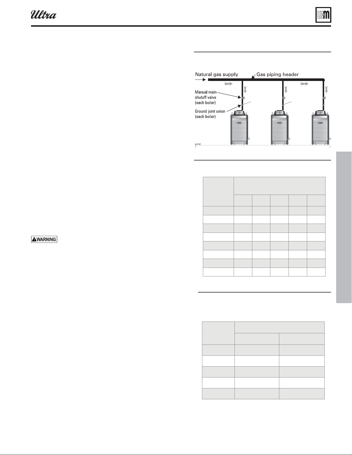
Manifolded gas supply lines
1. Construct gas header for multiple boilers using Figure 107 and
the sizing tables below. Refer to the National Fuel Gas Code for
other conditions.
2. Provide manual shutoff gas valve and ground joint union as shown
in Figure 33, page 29 and Figure 107 for each boiler. When gas
line enters from top of the boiler, the boiler internal gas piping
provides a drip leg.
3. A ¾” NPT gas piping riser from header to boiler will be large
enough for most jobs. Ensure the piping is large enough so that
the minimum pressure at the boiler will be at least 5 inches water
column with all connected appliances fi ring.
®
Series 4
gas-fired water boiler — Boiler Manual
inches
2.62 5.24
3.45 6.90
4.02 8.04
5.17 10.3
6.16 12.3
Figure 107 Common as line for multiple oilers
cuic feet per hour . speci c rait
520 1050 1600 3050 4800
350 730 1100 2100 3300
285 590 890 1650 2700
245 500 760 1450 2300
215 440 670 1270 2000
175 360 545 1020 1650
150 305 460 870 1400
120 250 380 710 1130
Figure 108 ipe capacit for . speci c rait natural
as
Figure 109 uialent lenths of straiht pipe for
tpical as line ttins
Loading ...
Loading ...
Loading ...