Loading ...
Loading ...
Loading ...
Part number 550-100-400/0119
62
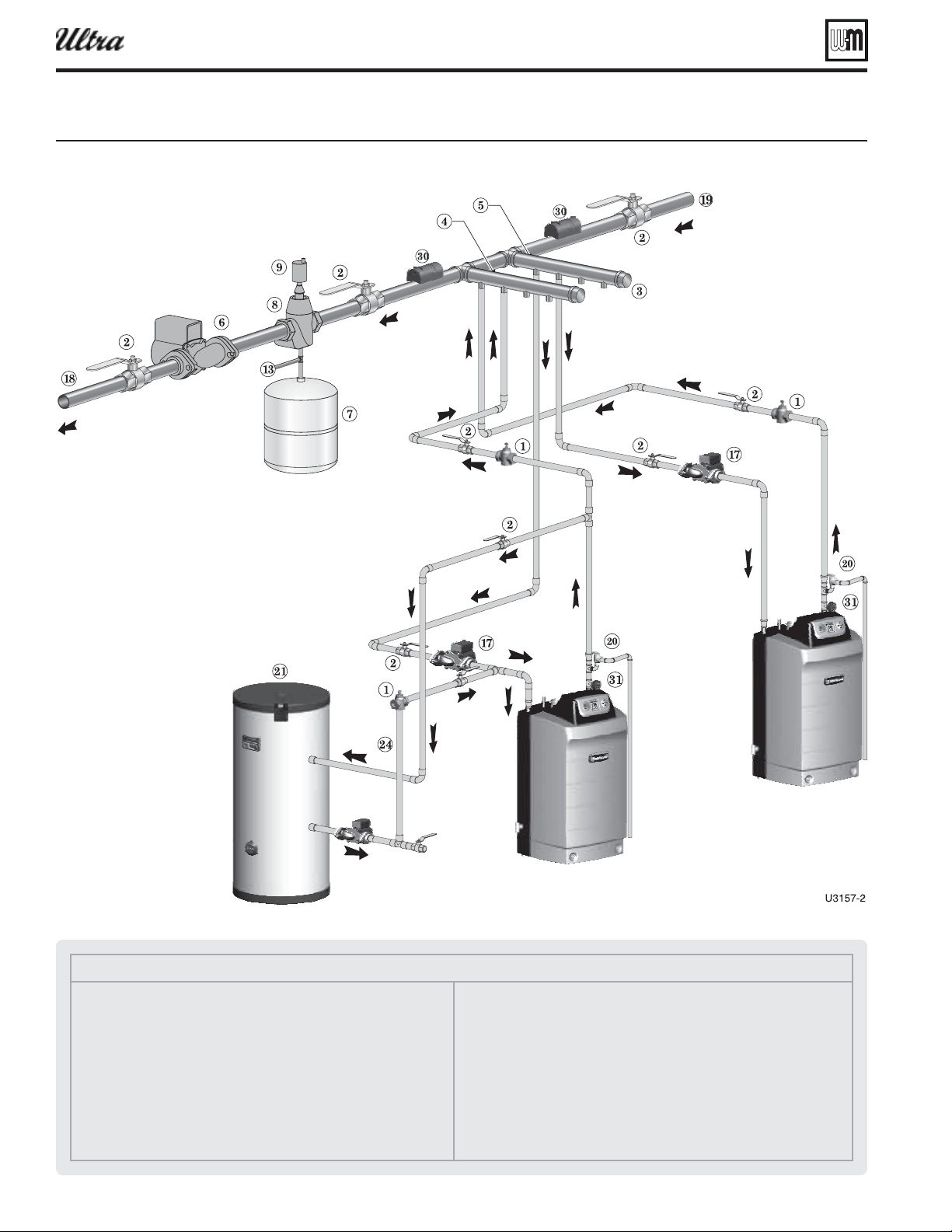
Multiple boiler installations (continued)
Legend — Figure 63
1 Flow/check valve (each boiler)
2 Isolation valves (when used)
3 Caps
4 Easy-Fit® Manifold (supply) — layout and size per page 60
5 Easy-Fit® Manifold (return) — layout and size per page 60
6 Primary circulator
7 Expansion tank (diaphragm type)
8 System air eliminator
9 System automatic air vent
13 Cold water supply
17 Boiler circulator (each boiler)
18 System supply
19 System return
20 Boiler relief valve and discharge piping, installed per Ultra Boiler Manual
21 Indirect-fi red storage water heaters (Weil-McLain AQUA PLUS shown) —
Example is shown connected to one boiler of the system. Preferably, use
the last boiler in the lead/lag sequence and set its Priority to
so it will switch to DHW fi ring and turn off its boiler circulator on a call
for domestic water heating.
24 DHW boiler-side circulator
30 Strap system supply and return sensors to lines as shown, at least 6 pipe
diameters (but no more than 3 feet) from boiler connection tees.
32 Temperature/pressure gauge
Figure 63 ipin laout tpical pipin for multiple Ultra oilers usin eil-cLain as-it manifolds -oiler sstem
®
Series 4
gas-fired water boiler — Boiler Manual
Loading ...
Loading ...
Loading ...