Loading ...
Loading ...
Loading ...
Part number 550-100-400/0119
20
®
Series 4
gas-fired water boiler — Boiler Manual
Sidewall vent/air termination: Separate pipes
Figure 14
eet los eet los eet los
- 100 2 100 2
Not
alloed
- 100 2 100 2
- Not alloed 100 2
- Not alloed 30 2 100 2
- Not alloed Not alloed 100 2
- Not alloed Not alloed 100 2
Install pipe reducers to adapt from pipe sie used to the outside
diameter reuired at the oiler. ou do not hae to reduce allo-
ale pipe lenth for the reducers.
Ultra- and oilers installed ith -inch ent pipin
automaticall derate due to the pressure loss in the ent and air
pipin. The derate ranes up to for the Ultra- at feet
or for the Ultra- at feet.
or pipin usin more than elos reduce maimum alloale
lenth
feet for each additional -inch elo or
feet for each additional or -inch lon radius elo
feet for each or -inch short radius elo
feet for each or -inch -deree elo.
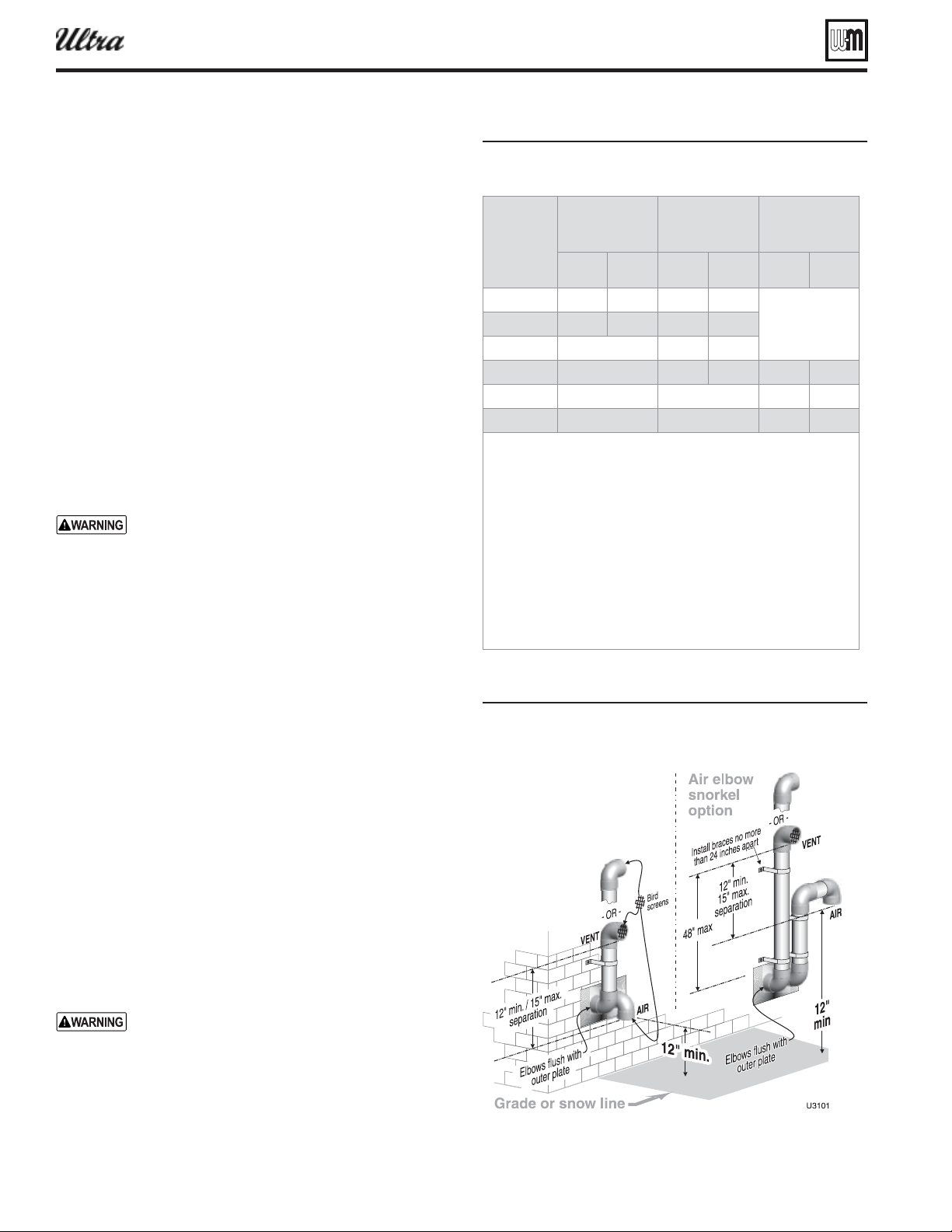
Figure 15 Sideall termination separate pipes
con uration options and minimum clearances
from ent to air terminations
Allowable vent/air pipe materials
1. Use only the materials listed in Figure 13, page 19 .
2. The Weil-McLain vent termination kit includes inside and
outside wall plates, bird screens, and mounting hardware to
secure the plates (kit included with boiler).
Maximum piping length
1. Locate the terminations such that the total air piping and vent
piping from the boiler to the termination will not exceed the
maximum length given in Figure 14 .
2. Maximum lengths listed in Figure 14 allow for 2 elbows. Ad-
ditional elbows required a reduction in maximum length as
explained in the table notes.
Connecting from termination to boiler
1. Install the terminations as instructed in the following. Then
proceed to page 82 to complete the air and vent piping be-
tween the termination and the boiler.
Determine location — separate elbows
A gas vent extending through an exterior wall shall
not terminate adjacent to the wall or below build-
ing extensions such as eaves, parapets, balconies
or decks. Failure to comply could result in severe
personal injury, death or substantial property dam-
age.
1. Locate the vent/air terminations using the following guide-
lines.
2. The air piping must terminate in a down-turned elbow as
shown in Figure 15 . This arrangement avoids recirculation
of fl ue products into the combustion air stream.
a. Apply the confi guration on the left side of Figure 15 unless
the terminations would fail to meet minimum clearance
to grade or snow line.
b. Apply the confi guration on the right side of Figure 15
when the terminations need to be raised higher to meet
clearance to grade or snow line.
c. The vent and air pipes may run up as high as 4 feet, as
shown in Figure 15 right side with no enclosure. The vent
and air pipes must be secured with braces, and all clear-
ances and lengths must be maintained. Space braces no
further than 24 inches apart. (See WARNING below for
extremely cold climates.)
d. External venting greater than 4 feet requires an insulated
enclosure around the vent and air pipes. The vent and air
terminations must exit through the enclosure as shown
in Figure 15 , maintaining all required clearances.
3. The vent piping must terminate in an elbow pointed outward
or away from the air inlet, as shown in Figure 15 .
Do not exceed the maximum lengths of the outside
vent piping shown in Figure 15 . Excessive length
exposed to the outside could cause freezing of con-
densate in the vent pipe, resulting in potential boiler
shutdown. In extremely cold climates, install an
insulated chase around the vent piping, particularly
when using longer lengths. The chase must allow
for inspection of the vent pipe, and insulation must
be protected from water.
Loading ...
Loading ...
Loading ...