Loading ...
Loading ...
Loading ...
Part number 550-100-400/0119
59
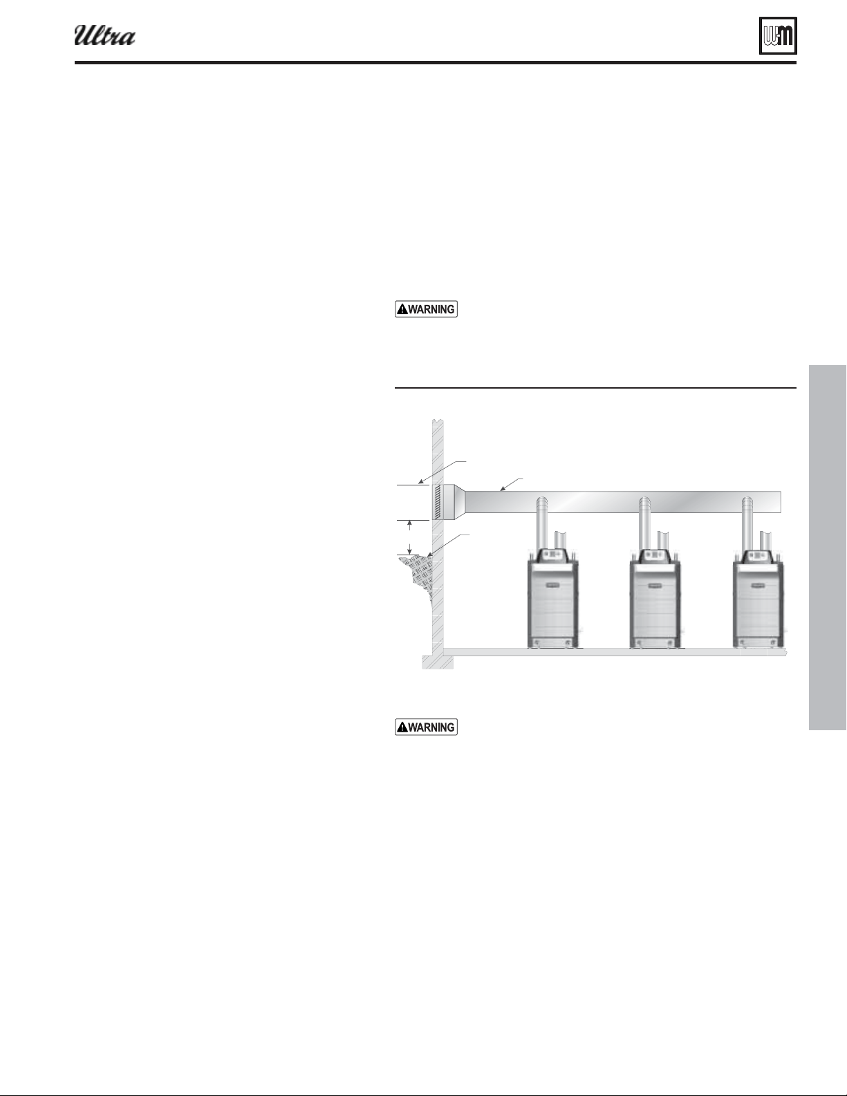
Figure 59 anifolded comustion air option
1ΣÈä
À6iÌ
£Ó¸Ê
À>`iÊÀ
ÃÜÊi
ÕÊÎÊviiÌÊLiÜÊ>ÞÊÛiÌÊÌiÀ>ÌÊÜÌÊ£äÊviiÌ
À6iÌÀ6iÌ
ÀÊ`ÕVÌ
Multiple boiler installations (continued)
®
Series 4
gas-fired water boiler — Boiler Manual
Manifolded combustion air option
1. Multiple Ultra boilers can use a common combustion air manifold.
a. See Figure 139, page 138 for minimum cross sectional area of
combined air ducts.
b. Provide minimum clearance to adjacent vents and grade/snow line
as shown in Figure 59 .
c. Provide minimum free area in duct (adjusted for louver restriction)
of
total boiler input.
d. If combustion air damper is used, wire to boilers to prevent opera-
tion except after damper has opened.
ONLY air piping can be combined. DO NOT use combined
vent piping. Flue gas leakage and boiler component damage
can occur. Failure to comply could result in severe personal
injury, death or substantial property damage.
DO NOT use common venting — the manifold option is
only for combustion air — all vent pipes must be routed and
terminated individually as described in this manual.
See Figure 139, page 138 for minimum cross sectional area
of combined air ducts.
OR
Calculate required cross section (for area in square inches):
Example: A multiple boiler system with (6) Ultra-155 boilers
has a total input of 6 x 155 = MBH (930,000 Btuh). The
required duct cross sectional area is:
Loading ...
Loading ...
Loading ...