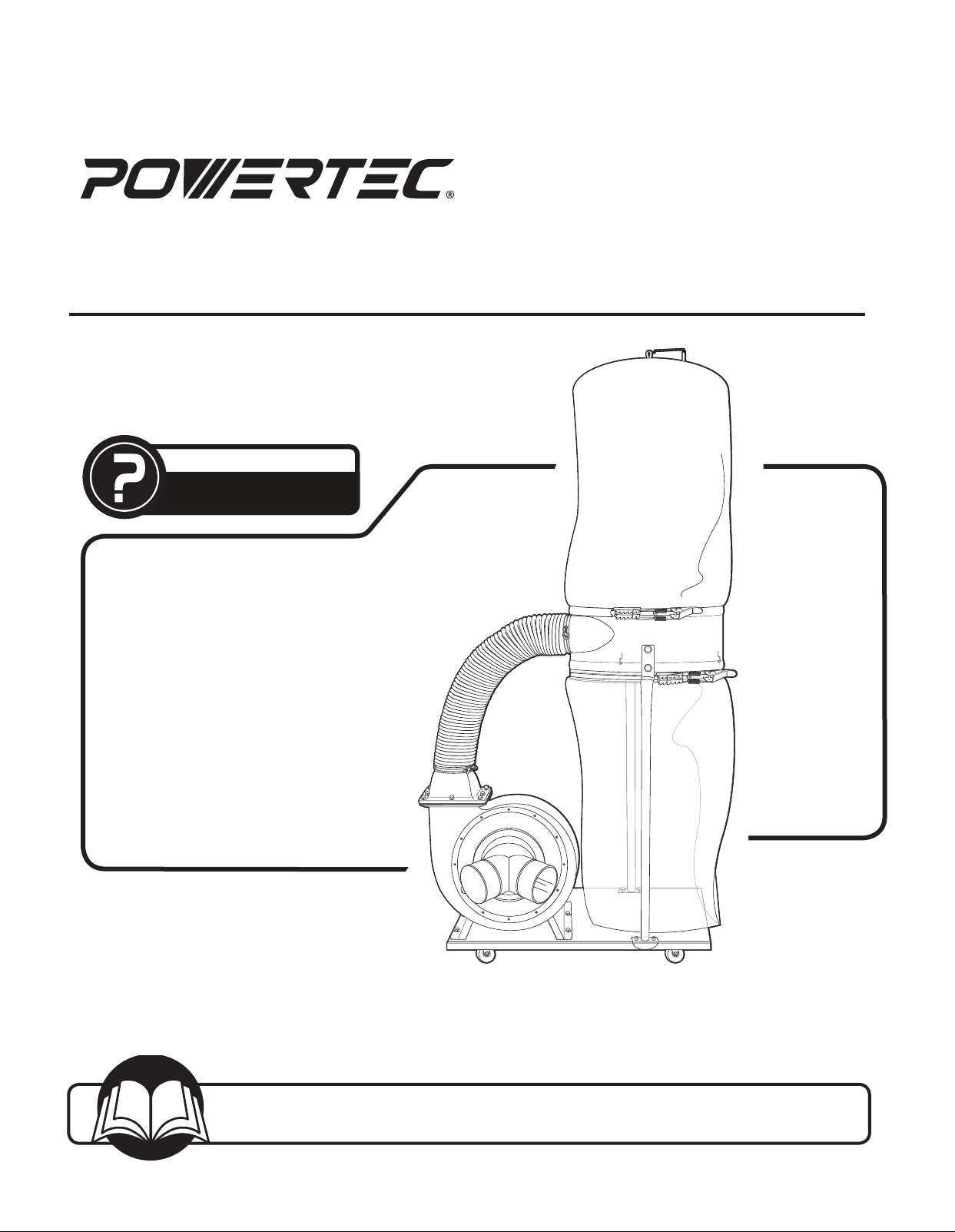
Owner’s Manual
Model No. DC1512
17-0619
You will need this manual for safety instructions, operating procedures, and warranty.
Put it and the original sales invoice in a safe, dry place for future reference.
Visit us on the web at www.southerntechllc.com
Dust Collector
QUESTION...
1•847•780•6120
Horsepower ................................ 1.5 HP
Voltage .................................120/240V
Hertz ......................................60 Hz
Phase .........................................1
Motor Speed ............................3450 RPM
Air Capacity ............................. 1550 CFM
Max. Static Pressure .............................9"
Main Inlet Size ..................... 4" (101.6 mm) x 2
Impeller Type ............................Radial Fin
Impeller Size .......................12 3/4"(324 mm)
Collection Bags
Upper bag (filter) .........................2.5 micron
Lower bag( collection) .........................plastic
Bag Overall Dimensions ................. 19-1/2" x 33"
Weight .............................106 lbs (48 kgs)
NOISE DATA
a weighted sound pressure level measuring (no load)
Operators position ............................ 85dB
a weighted sound pressure level measuring (loaded) 87dB
TABLE OF CONTENTS
PRODUCT
SPECIFICATIONS
SAFETY RULES 1
Work Preparation
Work Area Preparation
Tool Maintenance
Tool Operation
Specific Safety Instructions
ASSEMBLY 2
Unpacking
Installation
Test
Power Source
Grounding Instructions
Extension Cords
Motor
Electrical Connections
OPERATION 7
Basic Operations
MAINTENANCE 11
General Maintenance
Cleaning
Lubrication
Machine Storage
Tool Repairs
TROUBLESHOOTING 12
PARTS ILLUSTRATION & 14
LIST
WARRANTY 13
SECTION PAGE
SAFETY RULES
1
WARNING
For your own safety, read and understand all warnings
and operating instructions before using any tool or
equipment.
WARNING
Some dust created by power sanding, sawing, grinding,
drilling and other construction activities contains chemicals
known to the State of California to cause cancer, birth
defects or other reproductive harm.
Some examples of these chemicals are:
• Lead from lead-based paints.
• Crystalline silica from bricks and cement and
other masonry products.
• Arsenic and chromium from chemically-
treated lumber.
Your risk from these exposures varies, depending on how
often you do this type of work. To reduce your exposure to
these chemicals: work in a well ventilated area and work
with approved safety equipment. Always wear OSHA/
NIOSH approved, properly fitting face mask or respirator
when using such tools.
WARNING
Always follow proper operating procedures as defined in
this manual even if you are familiar with the use of this or
similar tools. Remember that being careless for even a
fraction of a second can result in severe personal injury.
WORK PREPARATION
• Wear proper apparel. Do not wear loose clothing,
gloves, neckties, rings, bracelets or other jewelry which
may get caught in moving parts of the tool.
• Wear protective hair covering to contain long hair.
• Wear safety shoes with non-slip soles.
• Wear safety glasses complying with United States ANSI
Z87.1. Everyday glasses have only impact resistant
lenses. They are NOT safety glasses.
• Wear face mask or dust mask if operation is dusty.
• Be alert and think clearly. Never operate power tools
when tired, intoxicated or when taking medications that
cause drowsiness.
WORK AREA PREPARATION
• Keep work area clean. Cluttered work areas invite
accidents.
• Do not use power tools in dangerous environments. Do
not use power tools in damp or wet locations. Do not
expose power tools to rain.
• Work area should be properly lit.
• Ground all tools. Proper electrical receptacle should
1
SAFETY RULES
be available for tool. Three-prong plug should be
plugged directly into properly grounded, three-prong
receptacle. If an adapter is used to accomodate a
two-prong receptacle, the adapter lug MUST be to a
known ground.
• Extension cords should have a grounding prong and
the three wires of the extension cord should be of the
correct gauge.
• Keep visitors at a safe distance from work area.
• Keep children out of the work area. Ensure your work
shop is child-proof. Use padlocks, master switches or
remove switch keys to prevent any unintentional use of
power tools.
TOOL MAINTENANCE
• Always unplug tool prior to inspection.
• Consult manual for specific maintaining and
adjusting procedures.
• Keep tool lubricated and clean for a safe operation.
• Remove adjusting tools. Form habit of checking to
see adjusting tools or accessories are removed before
switching tool on.
• Keep all parts in working order. Check to determine that
guard or other parts will operate properly and perform
their intended function.
• Check for damaged parts. Check for alignment of
moving parts, binding, breakage, mounting and any
other condition that may affect tool’s operation.
• A guard or any other part that is damaged should be
properly repaired or replaced. Do not perform makeshift
repairs.
TOOL OPERATION
• Use the right tool for your job. Do not force your tool or
attachment to do a job for which it was not designed.
• Avoid accidental start-up. Make sure that the tool is in
the “OFF" position before plugging in.
• Never leave tool running unattended.
• Know your tool. Learn the tool’s operation, application
and specific limitations before using it.
CAUTION
Think safety! Safety is a combination of operator common
sense and alertness at all times when tool is being used.
WARNING
Do not attempt to operate tool until it is completely
assembled according to the instructions.
SAVE ALL WARNINGS AND INSTRUCTIONS
FOR FUTURE REFERENCE
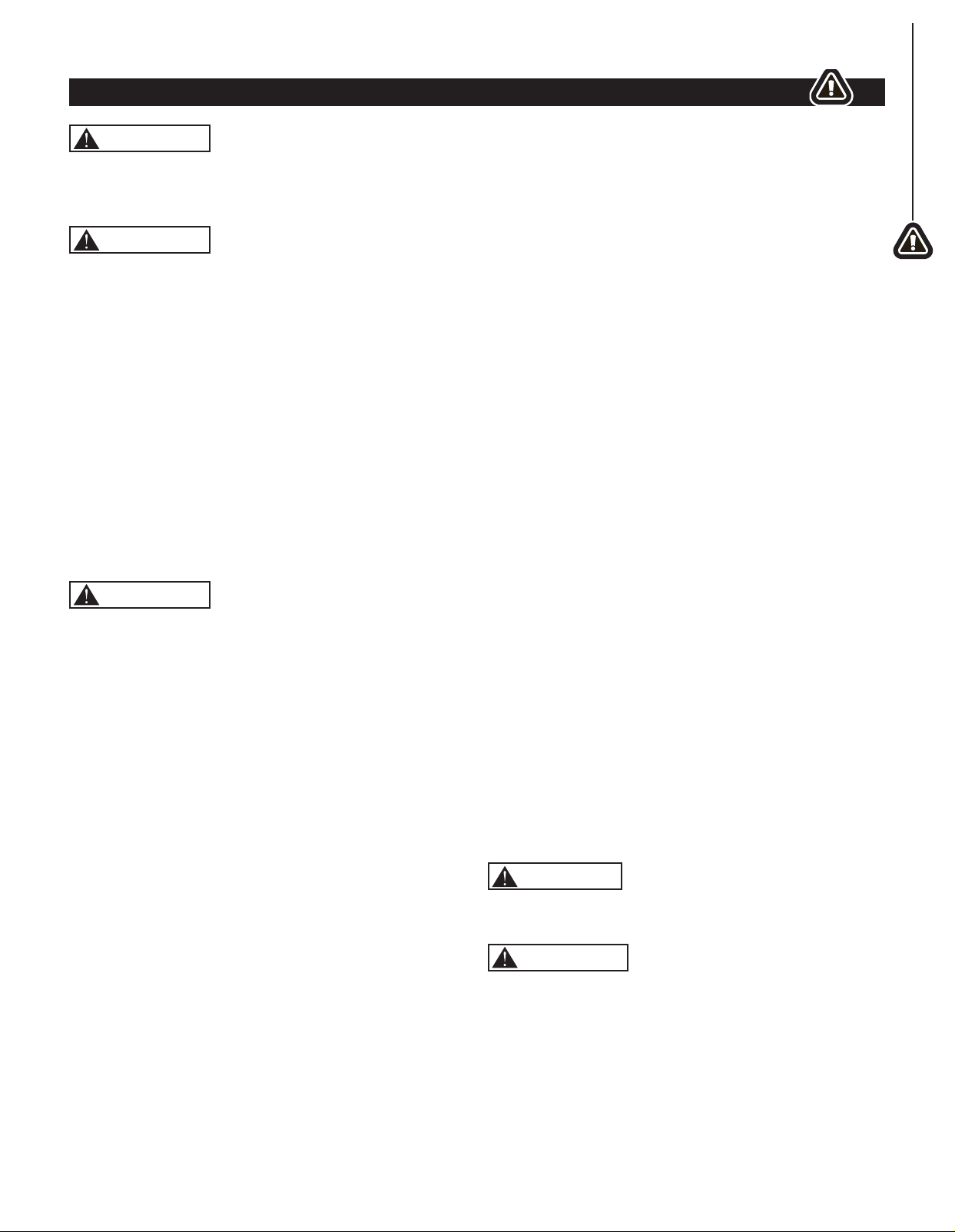
UNPACKING
Refer to Figure 1.
Check for shipping damage. Check immediately whether all
parts and accessories are included. If anything is missing or
broken, contact your retailer or call 847-780-6120.
• Carefully remove all contents from shipping carton. The
shipping carton contains:
ITEM DESCRIPTION QUANTITY
A Flexible Hose 5" 1
B Collector Support Frame 1
C Main Frame Housing 1
D Base Plate 2
E Upper Bag Support Rod 1
F Collector Frame Support Rod 2
G Inlet Connector, Dual 1
H Filler Bag (Logo) 1
I Collection Bag (Plastic) 1
J Hose Clamp, 5" 2
K Bag Clamps 2
L Outlet Gasket 1
M Outlet Flange 1
ASSEMBLY
2
2
2
SAFETY RULES
SPECIFIC SAFETY INSTRUCTIONS
2
WARNING
Read and understand the instruction manual before
operating the dust collector. Basic precautions listed
below should always be followed when using your dust
collector to reduce the risk of injury, electrical shock
or fire.
• This dust collector is designed to collect sawdust only.
• Never attempt to use this dust collector to collect water
or any other liquids.
• Never try to use this dust collector to collect large
wood pieces.
• Never attempt to use this dust collector to collect metal
materials such as screws, nails or other metal parts.
• Never attempt to use this dust collector to collect
flammable or combustible dust/gas. DO NOT use near
any flammable or combustible liquids.
• Never attempt to use this dust collector to collect
anything that is burning or smoking.
• DO NOT use outdoors or on wet surfaces.
• Turn machine off, disconnect power cord and ensure all
moving parts have stopped completely before servicing
or changing/emptying the bags.
• Always wear approved eye protection and respirator
when emptying collection/filter bags.
• Ensure the machine is turned off before unplugging the
dust collector.
• Unplug dust collector when not in use.
• Grasp the plug not the cord to unplug the dust collector.
• Never pull the dust collector by the power cord.
• Keep vacuum hoses and electrical cord out of
traffic areas.
• ALWAYS ensure collection/filter bags are secured
in place.
• Do not place your hand or tools near the open inlet
while operating. Serious personal injury or damage to
the machine can happen.
• Always connect dust collector to the matched
power source.
• Place unit on stable, level surface.
• Never operate the dust collector with all blast
gates closed.
IMPORTANT : Always consider safety first as it applies
to your individual working conditions, the environment in
every shop is different.
SAVE ALL WARNINGS AND INSTRUCTIONS
FOR FUTURE REFERENCE
Parts Bag Containing
N Hex Head Bolt 5/16-18" x 1/2"
36
O Pan Flange Head Screw
3 / 16"- 24 x 3 / 8" 1
P Open End Wrench 10-12 mm 1
Q Hex Wrench 5 mm (to be used
to remove/replace impeller only)
2
R Casters 4
S Foam Strip 1
Owner's Manual (not shown)
A
B
E
F
H
I
P
G
D
J
R
C
M
L
K
Figure 1
N
O
Q
S
ASSEMBLY
3
ASSEMBLY
INSTALLATION
Refer to Figures 2 - 12
CAUTION
Do not attempt assembly if parts are missing. Call the
Customer service line to obtain replacement parts.
WARNING
Do not operate dust collector until completely assembled.
Do not operate this tool until you have completely read
and understood this manual.
NOTE: After unit is assembled dispose of all packaging
material in an environmentally safe way.
Tools required for assembly:
• 10-12 mm Open End Wrench
• Flat Head Screwdriver
WARNING
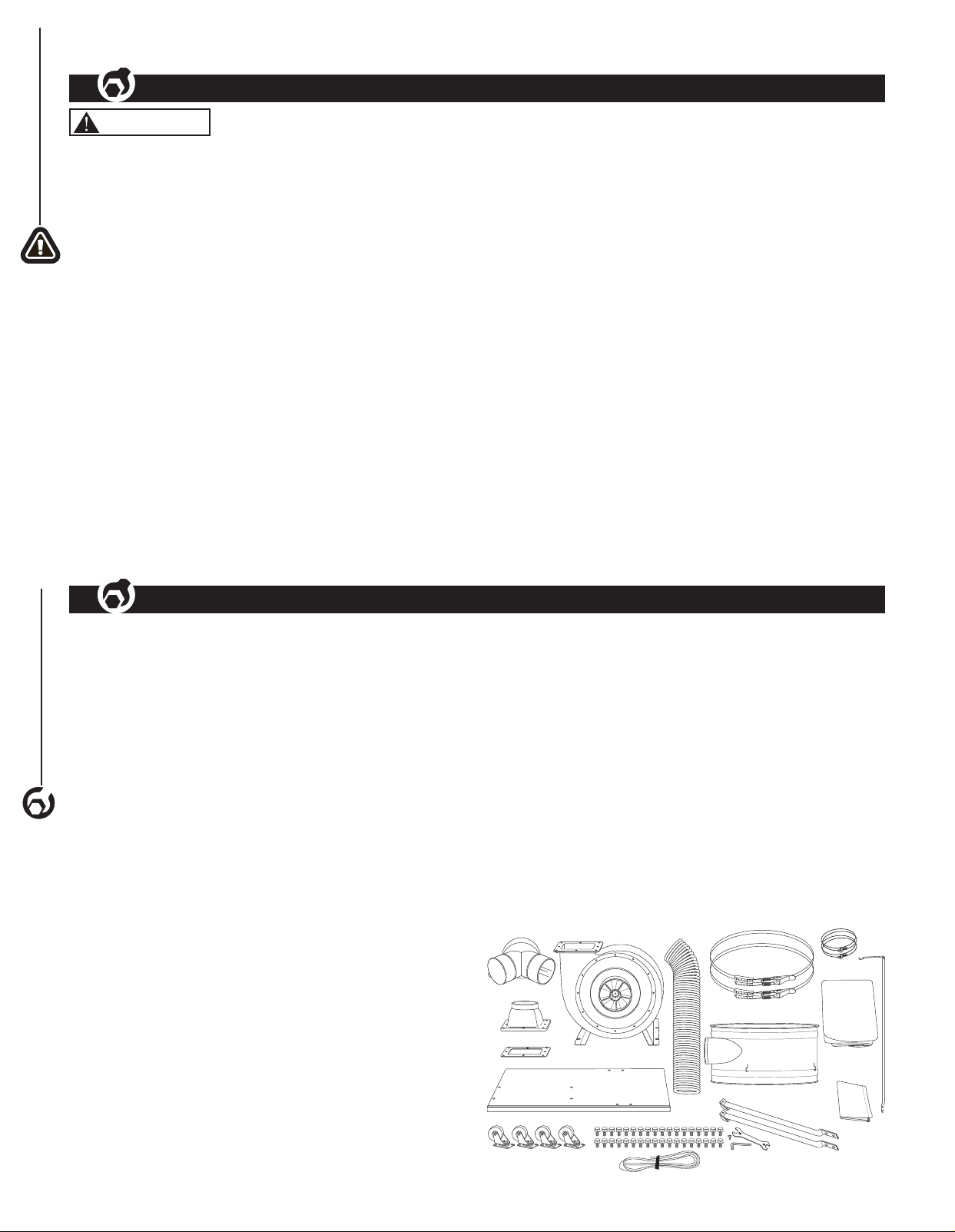
Ensure the dust collector is unplugged before assembling.
1. Turn the base plate upside down as shown and attach
the four casters using 16 hex head bolts. Tighten with
12 mm wrench.
Figure 2
Base Plate
Hex
Head
Bolt
Caster
2. Turn the base plate right side up and locate the four
threaded holes for the main frame housing.
Figure 3
Threaded holes
for Main Frame
Housing
Threaded holes for
Collector Support Rods
3. Align the main frame housing with the four threaded
holes in the base plate, use four hex head bolts to
secure and tighten with 12 mm wrench.
Figure 4
Main Frame Housing
Hex
Head
Bolts
Hex
Head
Bolts
4. Place the two collector supports rods on the base
plate as shown and use four hex head bolts to secure,
tighten with 12 mm wrench.
NOTE: Make sure the rods are assembled with the
bend out.
Figure 5
Main Frame
Housing
Hex Head Bolts
Collector
Supports Rod
(Back)
Bend Out
Collector
Supports Rod
(Front)
5. Orient the inlet flange of the collector support frame
to face the main housing outlet funnel, attach the
collector frame support rod on the front of the machine
to the collector support frame. Use two hex head bolts
to secure, tighten with 12 mm wrench.
Figure 6
Inlet Flange
Facing Main
Frame Housing
Hex Head Bolts
Collection
Support Frame
Collector Support
Rod (Front)
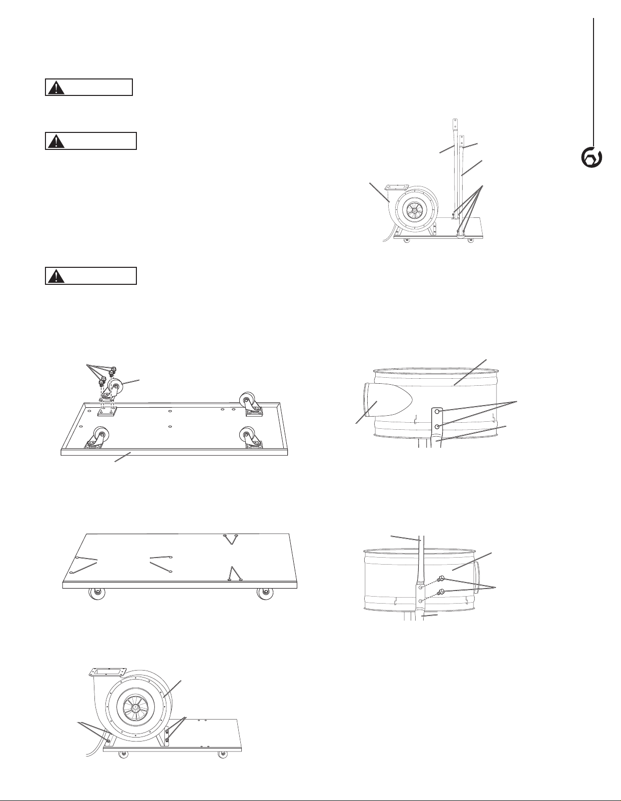
6. Hold the back of the collection support frame and slide
the upper support rod between the collector support
rod and collector support rod (back). Secure with two
hex head bolts, tighten bolts with 12 mm wrench.
Figure 7
Hex Head
Bolts
Collection
Support
Frame
Collector Support Rod (Back)
Upper Support Rod
7. Place the gasket onto the top of the opening in the
main frame housing.
8. Place the adapter on top of the gasket and use
eight hex head bolts to secure. Tighten bolts with
12 mm wrench.
4
ASSEMBLY
Figure 8
Adapter
Main Frame
Housing
Gasket
9. Place the hose clamps on each end of the 5" flexible
hose. Place one end over the adapter on the main
frame housing and the other end on the outlet on the
collector support frame. Tighten screws on the hose
clamps to secure in place.
Figure 9
Collector
Support
Frame
Adhesive
Foam Strip
Hose
Clamp
Flexible
Hose
Adapter
10. Use the pan head screw to attach the dual inlet to the
6" opening of the main frame housing. Thighten with
phillips head screw driver.
Figure 10
Dual Inlet
Pan Head
Screw
Main Frame
Housing
11. Thread a bag clamp through the hemmed opening in
the filter bag.
Figure 11
Bag Clamp
Hemmed
Opening
12. Place the filter bag over the top of the collector
support frame and hook the top loop over the hook on
upper collection support rod. Secure the filter bag in
place by fastening the bag clamp.
13. Place the adhesive foam strip (supplied) around the
bottom of the dust collector support frame (Figure 9).
14. Place the plastic collection bag over the bottom of the
collector support frame and secure in place with the
second bag clamp.
Figure 12
Bag Clamp
Collection Bag
(plastic)
Upper
Collection
Rod Hook
Collection
Bag
Bag Clamp
Collector
Support
Frame
TEST
WARNING
Before starting the dust collector, make sure you have
read and understood the manual and you are familiar with
the functions and safety features on the machine. Failure
to do so may cause serious personal injury.
Run a test to ensure the dust collector operates properly
and the safety key works properly.
1. Ensure all tools used for assembly are removed from
the work area.
2. Plug the power cord into the correct receptacle.
(Refer to Power Source paragraph in this section of
the manual.)
3. Turn the dust collector ON. (Refer to On/Off Switch
paragraph in Operation section of the manual.)
4. If unusual noise or excessive vibration is noticed, shut
off the machine immediately and disconnect the cord
from the power source. Check all the assembled parts
once again and investigate to find the problem.
5. If the dust collector operates correctly, turn the
machine OFF and remove the safety key on the
switch. Once the safety key is removed, turn the
switch ON. The machine should not run with the
safety key removed.
If everything operates correctly the dust collector is ready
for use.
POWER SOURCE
WARNING
Do not connect dust collector to the power source until all
assembly steps have been completed.
The motor is designed for operation on the voltage and
frequency specified. Normal loads will be handled safely
on voltages not more than 10% above or below specified
voltage. Running the unit on voltages which are not within
the range may cause overheating and motor burn-out.
Heavy loads require that the voltage at motor terminals be
no less than the voltage specified on nameplate.
• Power supply to the motor is controlled by a single
pole locking rocker switch. Remove the key to prevent
unauthorized use.
• The motor is prewired to operate on a 120V power
supply circuit. The motor can be converted to operate
on a 240 power supply. See To Convert to 240 Power
Supply for instructions.
GROUNDING INSTRUCTIONS
WARNING
Improper connection of equipment grounding conductor
can result in the risk of electrical shock. Equipment
should be grounded while in use to protect operator from
electrical shock.
• Check with a qualified electrician if you do not
understand grounding instructions or if you are in doubt
as to whether the tool is properly grounded.
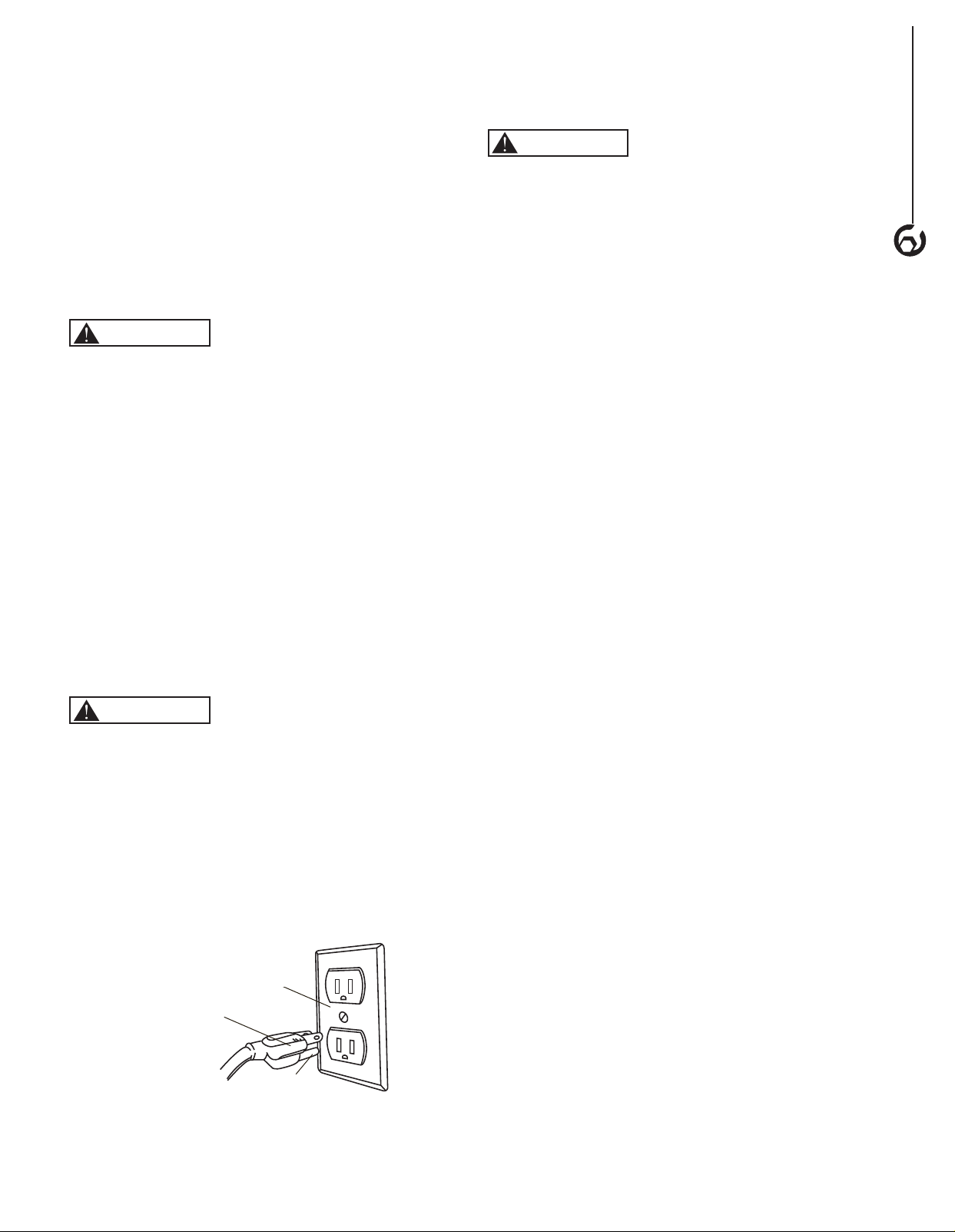
• This tool is equipped with an approved cord rated at
120V and a 3-prong grounding type plug (see Figure 13)
for your protection against shock hazards.
Figure 13
Properly Grounded Outlet
Grounding Prong
3-Prong Plug
Grounding plug should be plugged directly into a
properly installed and grounded 3-prong grounding type
receptacle, as shown (see Figure 13).
• Do not remove or alter grounding prong in any manner.
In the event of a malfunction or breakdown, grounding
provides a path of least resistance for electrical shock.
WARNING
Do not allow fingers to touch the terminals of plug when
installing or removing from outlet.
• Plug must be plugged into matching outlet that is
properly installed and grounded in accordance with
all local codes and ordinances. Do not modify plug
provided. If it will not fit in outlet, have proper outlet
installed by a qualified electrician.
• Inspect tool cords periodically, and if damaged, have
repaired by an authorized service facility.
• Green (or green and yellow) conductor in cord is the
grounding wire. If repair or replacement of the electric
cord or plug is necessary, do not connect the green (or
green and yellow) wire to a live terminal.
EXTENSION CORDS
• The use of an extension cord is not recommended.
The use of any extension cord will cause some drop in
voltage and loss of power.
• Wires of the extension cord must be of sufficient size to
carry the current and maintain adequate voltage.
• Use the table to determine the minimum wire size
(A.W.G.) extension cord.
• Use only 3-wire extension cords having 3-prong
grounding type plugs and 3-pole receptacles which
accept the tool plug.
• If the extension cord is worn, cut or damaged in any
way, replace it immediately.
• Extension Cord Length
Wire Size ..................................A.W.G.
Up to 50 ft ...............................14 gauge
NOTE: Using extension cords over 50 ft. long is not
recommended.
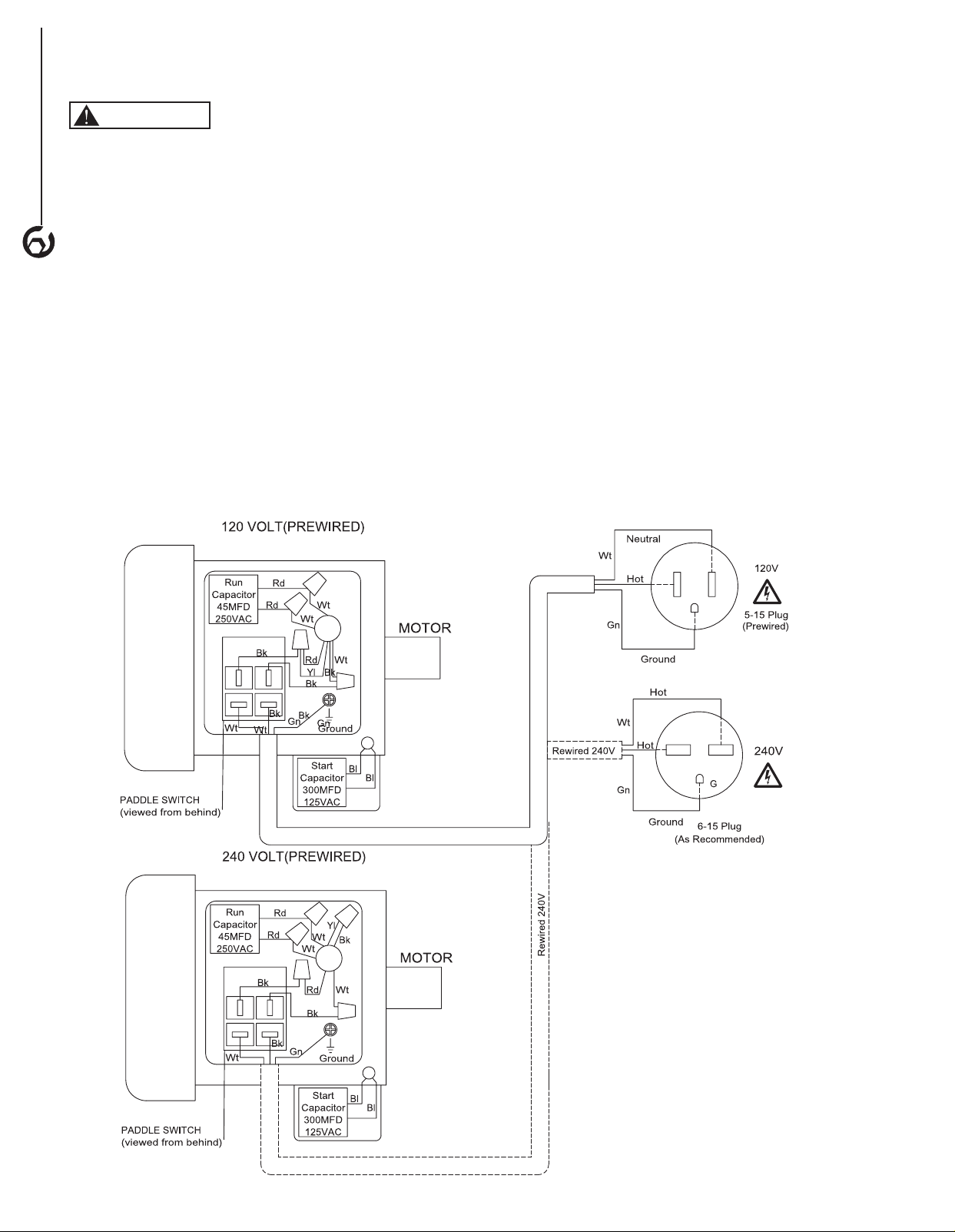
MOTOR
The dust collector is assembled with motor and wiring
installed. The electrical wiring schematic is shown in
Figure 14.
The permanently split capacitor motor has the following
specifications:
Horsepower (Peak HP) .......................... 1.5
Voltage ..................................120/240
Amp ........................................ 18/9
Hertz .........................................60
Phase .....................................Single
RPM .......................................3450
NOTE: These circuit requirements apply to a dedicated
circuit, where only one machine will be running at a
time. If this machine is connected to a shared circuit with
multiple machines running at the same time, consult with
a qualified electrician to ensure the circuit is properly sized
for safe operation.
5
ASSEMBLY
ELECTRICAL CONNECTIONS
WARNING
All electrical connections must be performed by a qualified
electrician. Make sure tool is off and disconnected
from power source while motor is mounted, connected,
reconnected or anytime wiring is inspected. Motor
and wires are installed as shown in wiring schematic
(See Figure 14). Motor is assembled with approved,
3-conductor cord to be used at 120 volts.
The power lines are inserted directly into the switch. The
green ground line must remain securely fastened to the
frame to properly protect against electrical shock. The
power supply to the motor is controlled by a single pole
locking rocker switch.
• Remove the key to prevent unauthorized use.
TO CONVERT TO 240V POWER SUPPLY
To convert the dust collector to 240V the switch box must
be rewired and a new plug attached. A qualified electrician
MUST inspect the switch box and new plug before the
dust collector is connected to the power source.
The 240V power supply circuit must have a verified
ground and meet these requirements:
Circuit Type ...........240V/240V, 60 Hz, Single Phase
Circuit Size ...............................15 Amps
Plug Receptacle ........................ NEMA 6-15
TO CONVERT
1. Make sure the tool is unplugged.
2. Open the switch box cover.
3. Follow the 240V wiring diagram on the inside of the
switch box cover. NOTE: The 240V wiring diagram
is also in Figure 14. Call the customer service line at
847-780-6120 for assistance if needed.
4. After rewiring make sure all wire nuts are tight and
use electrical tape to secure them in place.
5. Replace the plug on the existing power cord with
a NEMA 6-15 plug. The plug must be plugged into
matching outlet that is properly installed and grounded
in accordance with all local codes and ordinances.
6. Have the wiring inspected by a qualified electrician.
7. Replace the switch box cover.
6
ASSEMBLY
Figure 14
OPERATION
7
BASIC OPERATIONS
ON/OFF Switch
The keyed switch is intended to prevent unauthorized use
of the dust collector.
1. To turn the dust collector ON insert the yellow key into
the key slot in the center of the switch.
2. Push the key firmly into the slot, then push switch to
the ON position to start the dust collector.
3. To turn the dust collector OFF push the switch to the
down position.
4. Remove the yellow switch key, when the dust
collector has come to a complete stop, by gently
pulling it outward.
WARNING
Remove the switch key whenever the dust collector is not
in use.
Place it in a safe place and out of reach of children.
WARNING
ALWAYS lock the switch OFF when the dust collector is
not in use. Remove the key and keep it in a safe place.
In the event of power failure, blown fuse, or tripped
circuit breaker, turn the switch OFF and remove the key,
preventing accidental startup when power comes on.
Figure 15
Yellow Switch
Key
On/Off Switch
OPERATION
7
Operation
WARNING
ALWAYS guard against static electric build-up by
grounding all dust collection lines.
NOTE: This dust collector is designed to be a stationary
unit connected to a shop dust collection system or a
mobile unit.
NOTE: Only open blast gates being used if connected to a
shop dust collection system
1. For stationary usage, locate the dust collector out
of the way in a corner or separate room. Connect
the dust collector to a shop dust collection system
(not included). Follow all instructions included
with the shop dust collection system. See Shop
Dust Collection System Set-up section for more
information.
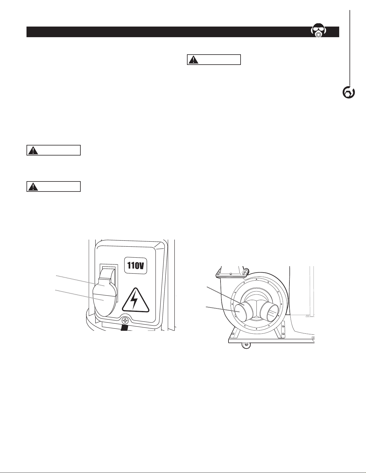
For mobile usage, position the dust collector close
to the the tools being used. Connect collector hoses
(not included) to the dust collector dual inlet, connect
the other end of the hoses to the machine outlets.
Secure both ends of the hose with hose clamps (not
included). NOTE: If only connecting to one machine
the second inlet, close the cap on the second collector
dual inlet.
2. This dust collector is designed to collect dust from up
to two machines running at the same time.
3. Turn the dust collector ON. (Refer to On/Off Switch
paragraph in this section of the manual.)
Figure 16
Dual
Inlet
Dual
Inlet
Cap
SHOP DUST COLLECTION SYSTEM SET-UP
NOTE: The following information is provided as a basic
guideline to help plan and setup your dust collection
system. To complete and fine tune the design of your
system several books and web based information is
available. Simply search for Dust collection system
design or Dust Collection Basics.
WARNING
ALWAYS guard against static electric build-up by
grounding all dust collection lines.
WARNING
RISK OF EXPLOSION. ALWAYS make sure there are no
open flames or pilot lights in the same room as the dust
collector.
Choose the duct material
For best results, use metal duct for the main line and
branch lines, then use short lengths of flexible hose to
connect each machine to the branch lines.
To prevent fire or explosion hazard when using plastic
duct material the system will need to be grounded against
static electrical charge build-up. See the Grounding the
Shop Dust Collection System section.
Metal Duct
• Metal duct is conductive, efficient and does not
contribute to static electrical charge build-up.
However, static charges are still produced when dust
particles strike other dust particles as they move
through the duct. Since metal duct is a conductor, it
can be grounded quite easily to dissipate any static
electrical charges.
• Choose metal duct that is manufactured for dust
collection systems. The metal duct should be made
of high quality metal duct with smooth welded internal
seams to minimize airflow resistance. This type of
duct usually connects to other ducts or elbows with
self-sealing clamps that make it easy to assemble
and disassemble.
• Avoid using metal duct material not manufactured for
dust collection systems.
Plastic Duct
• Plastic duct is economical and readily available.
It is simple to assemble and easily sealed against
air loss. The primary disadvantage of plastic duct
for dust collection is the inherent danger of static
electrical build-up.
Flexible Duct
• Flexible hose is used for short runs, small shops and
duct-to-tool connections. Flexible hoses are available,
in different materials such as polyethylene, PVC, cloth
hose dipped in rubber and even metal, including steel
and aluminum.
• Choose flexible hose designed for the movement of
solid particles, i.e. dust, grains, and plastics.
• The recommended flex hose material is metal.
• Non-perforated drainage type hoses and dryer vent
hoses are not recommended to be used with a dust
collection system.
GROUNDING THE SHOP DUST COLLECTION
SYSTEM
WARNING
ALWAYS guard against static electric build-up by
grounding all dust collection lines.
Plastic hose is abundant, relatively inexpensive, easily
assembled and air tight, making it a popular material to
be used in dust collection systems. Flexible hose (flex-
hose) is recommended when connecting the woodworking
machine to the dust collector. Plastic flex-hose and
plastic duct are insulators and MUST be grounded. If not
grounded the electrical discharge created, from the dust
particles moving against the walls of the plastic duct, may
cause an explosion and subsequent fire inside the system.
To Ground
To protect against static electrical build up inside a non-
conducting duct, a bare copper wire should be placed
inside the duct along its length and grounded to the dust
collector. You must also confirm that the dust collector is
continuously grounded through the electrical circuit to the
electric service panel.
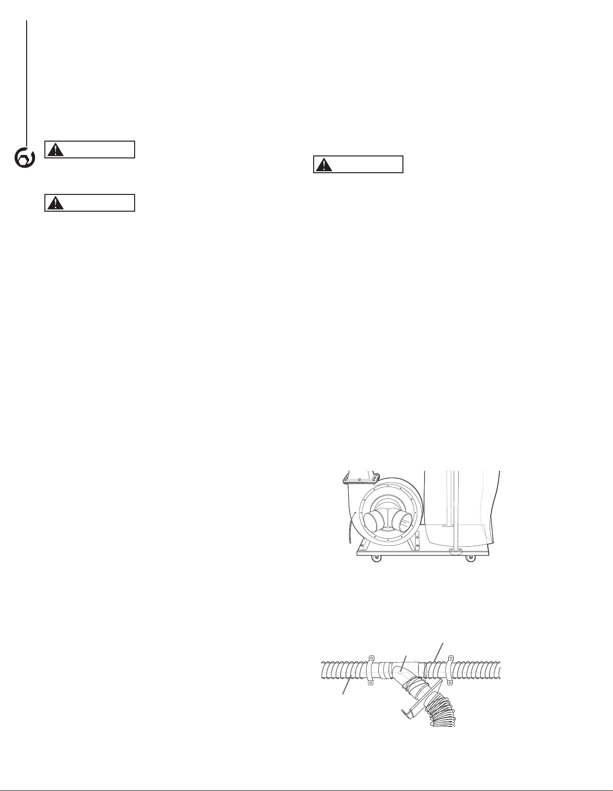
• Insert a continuous bare copper ground wire inside the
entire duct system and attach the bare ground wire to
each stationary woodworking machine and attach it to
the dust collector frame with a ground screw (Figure 17).
Figure 17
• Extend the bare copper wire down all branches of the
system. Make sure all wires are connected to each
other with wire nuts when two branches meet at a “Y” or
“T” connection (Figure 18).
Internal Copper Wire
Wire Nut
Figure 18
External Copper Wire
OPERATION
8

• Wrap the outside of all plastic ducts with bare copper
wire to ground the outside of the system against static
electrical build up. Make sure all wires are connected to
each other with wire nuts when two branches meet at a
“Y” or “T” connection (Figure 19).
Copper
Wire
Ground
Screw
Ground
Screw
Plastic
Gate
Metal Duct
Figure 19
• When plastic blast gates are used the grounding
wire must be jumped around the blast gate without
interruption to the grounding system.
• Ensure that each machine is properly grounded. Refer
to the machine owner's manual for correct procedure.
DUST COLLECTION SYSTEM LAYOUT
Use the following information as a guide to layout a dust
collection system for a small to medium shop. More
research or the help from an expert will be needed to
layout a dust collection system for a large shop.
NOTE: To complete and fine tune the design of your
system several books and web based information is
available. Simply search for Dust collection system
design or Dust Collection Basics.
1. Sketch the layout of the shop floor. Include each
machine and the dust collector.
2. Sketch the layout of the main line ducts and the
branch line ducts to connect each machine to the dust
collection system.
• Place the machines that produce the most saw
dust nearest to the dust collector
• The main line and secondary branch ducts should
be designed to be as short as possible.
• Keep direction changes to a minimum. Directional
change fittings increase the overall resistance
to flow.
• Used the largest corner radius possible when
changing hose or pipe direction, a gradual
directional change is more efficient.
• Each individual branch line should have a
blast gate.
3. Determine the required CFM to determine the size of
duct work needed.
• Each machine produces a different amount of
sawdust. The minimum amount of CFM needed to
move the sawdust is different for each machine.
• The Table 1 shows the approximate required
CFM per machine based on the dust port size.
NOTE: Place machines that generate the most
sawdust close to the dust collector (planers,
sanders).
NOTE: If a machine has multiple dust ports the
CFM required is the sum of all ports.
TABLE 1
MACHINE DUST
PORT SIZE
APPROXIMATE
REQUIRED CFM
2" 98
2.5" 150
3" 220
4" 395
5" 614
6" 884
7" 1203
8" 1570
9" 1990
10" 2456
• See Table 2 to help determine what size dust
port is needed on machines without a built-in
dust port.
TABLE 2
MACHINE DUST PORT
SIZE
Bandsaw 4"
Belt Sander (6" and smaller) 2"
Belt Sander (7"-9") 3"
Disc Sander (12" and smaller) 2"
Disc Sander (13-18") 4"
Drum Sander (24" and larger) 4 x 4"
Drum Sander (24" and smaller) 2 x 4"
Edge Sander (6" x 80" and larger) 5"
Edge Sander (6" x 80" and smaller) 4"
Jointer (6" and smaller) 4"
Jointer (8"-12") 5"
Lathe 4"
Miter/Radial-Arm Saw 2"
Router (mounted to table) 2"
Shaper 4"
Table Saw 4"
Thickness Planer (13" and smaller) 4"
Thickness Planer (14"-20") 6"
Widebelt Sander (18" and smaller) 5"
Widebelt Sander (24"-37" single head) 2 x 6"
Widebelt Sander (24"-51" double head) 5 x 4"
• Add the required CFM to your sketch for
each machine.
4. Determine the main line duct size.
• The velocity of the airflow must not fall below
3500 CFM.
• Using the inlet size of the dust collector as the
main line duct size will usually keep the air
velocity above 3500 CFM.
OPERATION
9
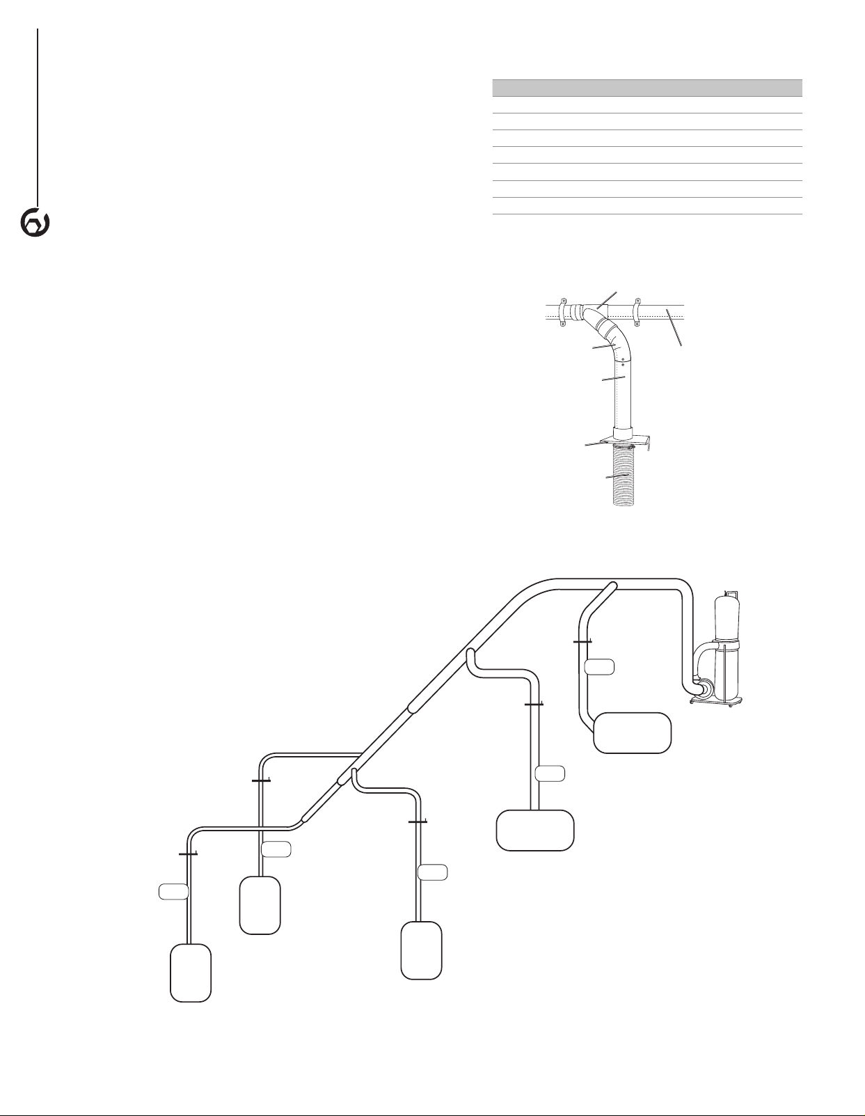
• Figure 20 gives an example of the CFM for each
machine, the dust collector inlet size being used
as the main line and the determined branch
line size.
5. Determine the branch line duct size.
• The velocity of the airflow must not fall below
4000 CFM.
• In small to medium size shops make the branch
size the size of the machine's dust port size.
• If the machine's dust port size is smaller than 4"
make the branch line 4" and neck the line down at
the machine.
• Add the determined branch line sizes to
the sketch,
• If two machines will share a branch line and both
will operate at the same time, add the required
CFM for each machine together. See Table 3 and
find the closest CFM to determine the branch line
size required. If the machines will never run at
the same time use the machine with the largest
dust port to determine the required branch line
size. Add a Y-connector and blast gate to each
machine to open/close when needed.
TABLE 3
TOTAL CFM BRANCH LINE SIZE
400 4"
500 4"
600 5"
700 5"
800 6"
900 6"
1000 6"
6. Plan the drop downs for each machine.
• Use blast gates wherever possible to control the
air flow (Figure 21).
Figure 21
Rigid Pipe
Elbow
Y connector
Blast Gate
Flex Hose to
Machine
Rigid Pipe
(Main Line)
OPERATION
10
4 in.
branch line
6 in.
branch line
6 in.
branch line
Dust
Collector
4 in.
branch line
4 in.
branch line
Figure 20
Planer
884 CFM
Sander
790 CFM
Table
Saw
395
CFM
Miter
Saw
98
CFM
Jointer
395
CFM

GENERAL MAINTENANCE
WARNING
Make sure the machine is turned off and the cord is
disconnected from the power source before servicing and
removing/replacing any components on the machine.
• Check the dust collector daily for loose mounting bolts,
screws, damaged wires, worn switch, full collection bag
and any other unsafe condition.
CLEANING
WARNING
ALWAYS wear a respirator and safety goggles when
emptying the collector bags.
Check and empty the collection bag on your dust collector
regularly. The machine operates at a much higher level of
efficiency when the collection bag is empty.
MAINTENANCE
11
MAINTENANCE
11
LUBRICATION
The sealed bearings in the motor have been
permanently lubricated at the factory. They require no
further lubrication.
MACHINE STORAGE
• When the dust collector is not in use, disconnect the
cord from the power source and store the machine in a
dry place.
• Do not expose the machine to rain.
• Ensure the cord is kept away from potential damage
sources such as; sharp objects, chemicals, heat
sources and water.
TOOL REPAIRS
• If power cord is worn, cut, or damaged in any way, have
it replaced immediately.
• Replace worn abrasives when needed.
• Replace any damaged or missing parts. Use parts list
to order parts. Any attempt to repair motor may create
a hazard unless repair is done by a qualified service
technician. Call the customer service line at
847-780-6120 for assistance.

12
TROUBLESHOOTING
SYMPTOM POSSIBLE CAUSE(S) CORRECTIVE ACTION
Motor will not start 1. Low voltage
2. Open circuit in motor or loose
connections
3. Defective switch
4. Defective capacitor
5. Switch key is removed
1. Check power line for proper voltage
2. Inspect all lead connections on motor for loose
or open connection
3. Replace switch
4. Replace capacitor
5. Insert switch key
Motor will not start;
fuses blown or circuit
breakers are tripped
1. Short circuit in line cord or plug
2. Short circuit in motor or loose
connections
3. Incorrect fuses or circuit breakers
in power line
1. Inspect line cord or plug for damaged insulation
and shorted wires
2. Inspect all lead connections on motor for loose
or shorted terminals or worn insulation on wires
3. Install correct fuses or circuit breakers
Unit has vibration or
noisy operation
1. Motor or components are loose
2. Motor mount is loose/broken
3. Motor fan is rubbing cover
4. Motor bearings faulty
5. Dust collector is not on a flat
surface
1. Inspect/replace any stripped or damaged bolts/
nuts and re-tighten.
2. Tighten/replace
3. Replace fan cover; replace loose/damaged fan
4. Call the customer service line at 847-780-6120
for assistance
5. Place the dust collector on a flat surface.
Loud, repetitious noise
or excessive vibration
coming from dust
collector
OR
Dust collector does
not adequately collect
dust or chips; poor
performance.
1. Dust collection bag is full
2. Dust collector hose restricted
3. The lumber is wet and dust is not
flowing through the hose smoothly
4. There is a leak in the hose
5. Restriction in duct line.
6. Dust collector is too far away, or
there are too many sharp bends in
the ducting.
7. The machine dust collection design
is inadequate.
1. Empty collection bag.
2. Remove hose from dust collector inlet and
unblock the restriction in the hose. A plumbing
snake may be necessary.
3. Process lumber with less than 20%
moisture content.
4. Inspect and replace hose.
5. Remove restriction in the duct line. A plumbing
snake may be necessary.
6. Relocate the dust collector closer to the
point of suction and rework ducting without
sharp bends.
7. Ensure the correct sized ducts and fittings
are used.
Sawdust blown into
the air from the dust
collector
Hose clamps or dust collection bag is
not properly clamped and secured.
Check hose and dust collection bag, ensure hose
and bag clamps are tight and completely over the
hose and bag.
TROUBLESHOOTING
12

Thank you for investing in a POWERTEC power tool. This product has been designed and manufactured to meet high
quality standards and is guaranteed for domestic use against defects in workmanship or material for a period of 12
months from the date of purchase. This guarantee does not affect your statutory rights.
SOUTHERN TECHNOLOGIES LLC. BENCH TOP AND STATIONARY POWER TOOL
LIMITED 1 YEAR WARRANTY AND 30-DAY SATISFACTION GUARANTEE POLICY
POWERTEC products are designed and manufactured by Southern Technologies LLC. All warranty communications
should be directed to Southern Technologies LLC by calling 847-780-6120 (toll free), 9 AM to 5 PM, Monday through
Friday, US Central Time.
30- DAY SATISFACTION GUARANTEE POLICY
During the first 30 days after the date of purchase, if you are dissatisfied with the performance of this POWERTEC tool
for any reason, you may return the tool to the retailer from which it was purchased for a full refund or exchange. You
must present proof of purchase and return all original equipment packaged with the original product. The replacement
tool will be covered by the limited warranty for the balance of the one year warranty period.
LIMITED ONE YEAR WARRANTY
This warranty covers all defects in workmanship or materials in this POWERTEC tool for a one year period from the
date of purchase. This warranty is specific to this tool. Southern Technologies, LLC reserves the right to repair or
replace the defective tool, at its discretion.
HOW TO OBTAIN SERVICE
To obtain service for this POWERTEC tool you must return it, freight prepaid, to POWERTEC. You may call (toll
free) 847-780-6120 for more information. When requesting warranty service, you must present the proof of purchase
documentation, which includes a date of purchase. POWERTEC will either repair or replace any defective part, at
our option at no charge to you. The repaired or replacement unit will be covered by the same limited warranty for the
balance of one year warranty period.
WHAT IS NOT COVERED
This warranty applies to the original purchaser at retailer and may not be transferred.
This warranty does not cover consumable items such as saw blades, knives, belts, discs, cooling blocks and sleeves.
This warranty does not cover required service and part replacement resulting from normal wear and tear, including
accessory wear.
This warranty does not cover any malfunction, failure or defect resulting from:
1) misuse, abuse, neglect and mishandling not in accordance with the owner’s manual.
2) damage due to accidents, natural disasters, power outage, or power overload.
3) commercial or rental use.
4) alteration, modification or repair performed by persons not recommended by POWERTEC.
DISCLAIMER
To the extent permitted by applicable law, all implied warranties, including warranties of MERCHANTABILITY or
FITNESS FOR A PARTICULAR PURPOSE, are disclaimed. Any implied warranties, that cannot be disclaimed under
state law are limited to one year from the date of purchase. Southern Technologies LLC. is not responsible for direct,
indirect, incidental or consequential damages. Some states do not allow limitations on how long an implied warranty
lasts and/or do not allow the exclusion or limitation of incidental or consequential damages, so the above limitations
may not apply to you. This warranty gives you specific legal rights, and you may also have other rights which vary from
state to state. Southern Technologies LLC., makes no warranties, representations, or promises as to the quality or
performance of its power tools other than those specifically stated in this warranty.
WARRANTY
13
13
WARRANTY
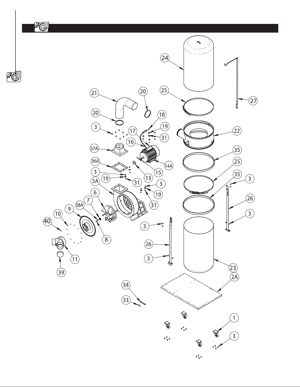
DUST COLLECTOR PARTS ILLUSTRATION
14
PARTS LIST
14

DUST COLLECTOR PARTS LIST
PARTS LIST
15
15
Item# Description Specification Q'ty
1 DC1512001 Caster 4
2A DC1512002 Base Plate 1
3 DC1512003 Screw Hex.flange.head 5 / 16"- x 1/2" 38
5A DC1512004 Collector 1
6 DC1512005 Turbo Fan 1
7 DC1512006 Washer 1
8 DC1512007 Cap Screw M6 x 1.0 x 19 mm 1
9 DC1512008 Inlet Cover 1
10 DC1512009 Screw 12
11 DC1512010 Inlet 1
13 DC1512011 Anti Vibration Plate 3
14A DC1512012 Motor 1
15 DC1512013 Pin 1
16 DC1512014 Power Cord 1
17 DC1512015 Switch 1
18 DC1512016 Flange Bolt 5/16" x 3/4" 4
19 DC1512017 Washer 5/16" 4
20 DC1512018 Hose Clamp.5" Expandable 2
21 DC1512019 Hose,5" Expandable 1
22 DC1512020 Collector 1
23 DC1512021 Bottom Bag 1
24 DC1512022 Top Bag With Logo 1
25 DC1512023 Belt Clamp 2
26 DC1512024 Collector Frame Support Rod 2
27 DC1512025 Upper Bag Supporter Rod 1
31 DC1512026 Nut 5/16" 8
33 DC1512027 Allen Key 1
34 DC1512028 Open And Wrench 10 x 12 mm 1
35 DC1512029 Foam 2
36A DC1512030 Outlet Gasket 1
37A DC1512031 Outlet Flange 1
38A DC1512032 Screw Hex.sic Head M6 x 13 1
39 DC1512033 Cap 1
40 DC1512034 Screw 1


Southern Technologies, LLC
3816 Hawthorn CT,
Waukegan, IL 60087