Sears Brands Management Corporation, Hoffman Estates, IL 60179, U.S.A.
Visit our website: www.craftsman.com
CAUTION: Before using this product,
read this manual and follow all safety
rules and operating instructions.
Operator’s Manual
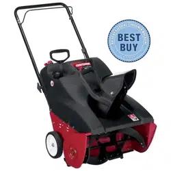
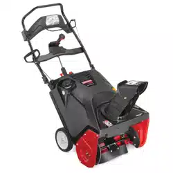
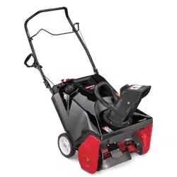
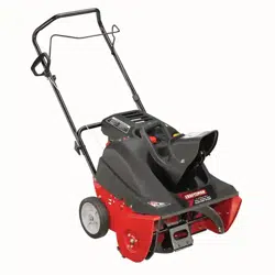
21” SNOW THROWER
Model No. 247.887822
• SAFETY
• UNPACKING
• ASSEMBLY
• OPERATION
• MAI
NTENANCE
• ESPAÑOL
®
Form No. 769-11710
(June 9, 2016)

2
TABLE OF CONTENTS
© Sears Brands, LLC
WARRANTY STATEMENT
MODEL NUMBERPRODUCT SPECIFICATIONS
Warranty Statement ...................................2
Safety Instructions
....................................3
Unpacking & Assembly
................................7
Operation
...........................................11
Service and Maintenance
............................14
Off-Season Storage
...................................18
Troubleshooting
.....................................19
Repair Protection Agreement
.........................20
Español
..............................................24
Service Numbers
............................ Back Cover
CRAFTSMAN LIMITED WARRANTY
FOR TWO YEARS from the date of sale, this product is warranted against defects in material or workmanship.
WITH PROOF OF SALE, a defective product will receive free repair or replacement at option of seller.
For warranty coverage details to obtain free repair or replacement, visit the web page: www.craftsman.com/warranty
This warranty covers ONLY defects in material and workmanship. Warranty coverage does NOT include:
• Expendable items that can wear out from normal use within the warranty period, including but not limited to augers, auger paddles, drift cutters, skid
shoes, shave plate, shear pins, spark plug, air cleaner, belts, and oil filter.
• Standard maintenance servicing, oil changes, or tune-ups.
• Tire replacement or repair caused by punctures from outside objects, such as nails, thorns, stumps, or glass.
• Tire or wheel replacement or repair resulting from normal wear, accident, or improper operation or maintenance.
• Repairs necessary because of operator abuse, including but not limited to damage caused by over-speeding the engine, or from impacting objects that
bend the frame, auger shaft, etc.
• Repairs necessary because of operator negligence, including but not limited to, electrical and mechanical damage caused by improper storage, failure to
use the proper grade and amount of engine oil, or failure to maintain the equipment according to the instructions contained in the operator’s manual.
• Engine (fuel system) cleaning or repairs caused by fuel determined to be contaminated or oxidized (stale). In general, fuel should be used within 30 days
of its purchase date.
• Normal deterioration and wear of the exterior finishes, or product label replacement.
This warranty is void if this product is ever used while providing commercial services or if rented to another person.
This warranty gives you specific legal rights, and you may also have other rights which vary from state to state.
Sears Brands Management Corporation, Hoffman Estates, IL 60179
Engine Oil: SAE 5W-30
Engine Oil Capacity: 20 ounces
Fuel: Unleaded Gasoline
Fuel Capacity: 2 quarts
Spark Plug: F6RTC
Spark Plug Gap: .020-.030”
Model Number ________________________________
Serial Number _________________________________
Date of Purchase _______________________________
Record the model number, serial number,
and date of purchase above.
3
SAFETY INSTRUCTIONS
TRAINING
• Read, understand, and follow all instructions on the machine and in the
manual(s) before attempting to assemble and operate. Failure to do so can
result in serious injury to the operator and/or bystanders. Keep this manual in a
safe place for future and regular reference and for ordering replacement parts.
• Be familiar with all controls and their proper operation. Know how to stop
the machine and disengage them quickly.
• Never allow children under 14 years of age to operate this machine. Children
14 and over should read and understand the instructions and safe operation
practices in this manual and on the machine and be trained and supervised
by an adult.
• Never allow adults to operate this machine without proper instruction.
• Thrown objects can cause serious personal injury. Plan your snow-throwing
pattern to avoid discharge of material toward roads, bystanders and the like.
• Keep bystanders, pets and children at least 75 feet from the machine while it
is in operation. Stop machine if anyone enters the area.
• Exercise caution to avoid slipping or falling, especially when operating in reverse.
PREPARATION
• Thoroughly inspect the area where the equipment is to be used. Remove all
doormats, newspapers, sleds, boards, wires and other foreign objects, which
could be tripped over or thrown by the auger/impeller.
• Always wear safety glasses or eye shields during operation and while
performing an adjustment or repair to protect your eyes. Thrown objects
which ricochet can cause serious injury to the eyes.
• Do not operate without wearing adequate winter outer garments. Do not wear
jewelry, long scarves or other loose clothing, which could become entangled in
moving parts. Wear footwear which will improve footing on slippery surfaces.
• Use a grounded three-wire extension cord and receptacle for all machines
with electric start engines.
• Disengage all control levers before starting the engine.
• Never attempt to make any adjustments while engine is running, except
where specifically recommended in the operator’s manual.
• Let engine and machine adjust to outdoor temperature before starting to
clear snow.
Safe Handling of Gasoline:
To avoid personal injury or property damage use extreme care in handling
gasoline. Gasoline is extremely flammable and the vapors are explosive.
Serious personal injury can occur when gasoline is spilled on yourself or your
clothes which can ignite. Wash your skin and change clothes immediately.
• Use only an approved gasoline container.
• Extinguish all cigarettes, cigars, pipes and other sources of ignition.
• Never fuel machine indoors.
• Never remove gas cap or add fuel while the engine is hot or running.
• Allow engine to cool at least two minutes before refueling.
• Never overfill fuel tank. Fill tank to no more than ½ inch below bottom of
filler neck to provide space for fuel expansion.
• Replace gasoline cap and tighten securely.
• If gasoline is spilled, wipe it off the engine and equipment. Move machine to
another area. Wait 5 minutes before starting the engine.
• Never store the machine or fuel container inside where there is an open
flame, spark or pilot light (e.g. furnace, water heater, space heater, clothes
dryer etc.).
• Allow machine to cool at least 5 minutes before storing.
• Never fill containers inside a vehicle or on a truck or trailer bed with a plastic
liner. Always place containers on the ground away from your vehicle before
filling.
• If possible, remove gas-powered equipment from the truck or trailer and
refuel it on the ground. If this is not possible, then refuel such equipment
on a trailer with a portable container, rather than from a gasoline dispenser
nozzle.
• Keep the nozzle in contact with the rim of the fuel tank or container opening
at all times until fueling is complete. Do not use a nozzle lock-open device.
WARNING
This symbol points out important safety instructions which, if not
followed, could endanger the personal safety and/or property of
yourself and others. Read and follow all instructions in this manual
before attempting to operate this machine. Failure to comply with these
instructions may result in personal injury. When you see this symbol, HEED
ITS WARNING!
WARNING
CALIFORNIA PROPOSITION 65
Engine Exhaust, some of its constituents, and certain vehicle components
contain or emit chemicals known to State of California to cause cancer and
birth defects or other reproductive harm.
DANGER
This machine was built to be operated according to the safe operation
practices in this manual. As with any type of power equipment,
carelessness or error on the part of the operator can result in serious injury.
This machine is capable of amputating fingers, hands, toes and feet and
throwing debris. Failure to observe the following safety instructions could
result in serious injury or death.
WARNING
Your Responsibility—Restrict the use of this power machine to
persons who read, understand and follow the warnings and instructions in
this manual and on the machine.
SAVE THESE INSTRUCTIONS!

4
SAFETY INSTRUCTIONS
OPERATION
• Do not put hands or feet near rotating parts, in the auger/impeller housing
or chute assembly. Contact with the rotating parts can amputate hands and
feet.
• The auger/impeller control lever is a safety device. Never bypass its operation.
Doing so makes the machine unsafe and may cause personal injury.
• The control levers must operate easily in both directions and automatically
return to the disengaged position when released.
• Never operate with a missing or damaged chute assembly. Keep all safety
devices in place and working.
• Never run an engine indoors or in a poorly ventilated area. Engine exhaust
contains carbon monoxide, an odorless and deadly gas.
• Do not operate machine while under the influence of alcohol or drugs.
• Muffler and engine become hot and can cause a burn. Do not touch. Keep
children away.
• Exercise extreme caution when operating on or crossing gravel surfaces. Stay
alert for hidden hazards or traffic.
• Exercise caution when changing direction and while operating on slopes.
• Plan your snow-throwing pattern to avoid discharge towards windows,
walls, cars etc. Thus, avoiding possible property damage or personal injury
caused by a ricochet.
• Prevent possible property damage or personal injury from object ricochet by
planning your snow throwing pattern to avoid discharge towards windows,
walls, cars, etc.
• Do not overload machine capacity by attempting to clear snow at too fast of
a rate.
• Never operate this machine without good visibility or light. Always be sure of
your footing and keep a firm hold on the handles. Walk, never run.
• Disengage power to the auger/impeller when transporting or not in use.
• Never operate machine at high transport speeds on slippery surfaces. Look
down and behind and use care when backing up.
• If the machine should start to vibrate abnormally, stop the engine,
disconnect the spark plug wire and ground it against the engine. Inspect
thoroughly for damage. Repair any damage before starting and operating.
• Disengage all control levers and stop engine before you leave the operating
position (behind the handles). Wait until the auger/impeller comes to
a complete stop before unclogging the chute assembly, making any
adjustments, or inspections.
• Never put your hand in the discharge or collector openings. Do not unclog
chute assembly while engine is running. Shut off engine and remain behind
handles until all moving parts have stopped before unclogging.
• Use only attachments and accessories approved by the manufacturer (e.g.
wheel weights, tire chains, cabs etc.).
• When starting engine, pull cord slowly until resistance is felt, then pull
rapidly. Rapid retraction of starter cord (kickback) will pull hand and arm
toward engine faster than you can let go. Broken bones, fractures, bruises or
sprains could result.
CLEARING A CLOGGED DISCHARGE CHUTE
Hand contact with the rotating impeller inside the discharge chute is the most
common cause of injury associated with snow throwers. Never use your hand to
clean out the discharge chute.
To clear the chute:
a. SHUT THE ENGINE OFF!
b. Wait 10 seconds to be sure the impeller blades have stopped
rotating.
c. Always use a clean-out tool, not your hands.
MAINTENANCE & STORAGE
• Never tamper with safety devices. Check their proper operation regularly.
Refer to the maintenance and adjustment sections of this manual.
• Before cleaning, repairing, or inspecting machine disengage all control
levers and stop the engine. Wait until the auger/impeller come to a complete
stop. Disconnect the spark plug wire and ground against the engine to
prevent unintended starting.
• Check bolts and screws for proper tightness at frequent intervals to keep the
machine in safe working condition. Also, visually inspect machine for any damage.
• Do not change the engine governor setting or over-speed the engine. The
governor controls the maximum safe operating speed of the engine.
• Snow thrower shave plates and skid shoes are subject to wear and damage.
For your safety protection, frequently check all components and replace
with original equipment manufacturer’s (OEM) parts only as listed in the
Parts pages of this Operator’s Manual. Use of parts which do not meet the
original equipment specifications may lead to improper performance and
compromise safety!
• Check control levers periodically to verify they engage and disengage
properly and adjust, if necessary. Refer to the adjustment section in this
operator’s manual for instructions.
• Maintain or replace safety and instruction labels, as necessary.
• Observe proper disposal laws and regulations for gas, oil, etc. to protect the
environment.
• Prior to storing, run machine a few minutes to clear snow from machine and
prevent freeze up of auger/impeller.
• Never store the machine or fuel container inside where there is an open
flame, spark or pilot light such as a water heater, furnace, clothes dryer etc.
• Always refer to the operator’s manual for proper instructions on off-season
storage.
• Check fuel line, tank, cap, and fittings frequently for cracks or leaks. Replace
if necessary.
• Do not crank engine with spark plug removed.
• According to the Consumer Products Safety Commission (CPSC) and the U.S.
Environmental Protection Agency (EPA), this product has an Average Useful Life
of seven (7) years, or 60 hours of operation. At the end of the Average Useful
Life have the machine inspected annually by an authorized service dealer to
ensure that all mechanical and safety systems are working properly and not
worn excessively. Failure to do so can result in accidents, injuries or death.

5
SAFETY INSTRUCTIONS
DO NOT MODIFY ENGINE
To avoid serious injury or death, do not modify engine in any way. Tampering
with the governor setting can lead to a runaway engine and cause it to operate
at unsafe speeds. Never tamper with factory setting of engine governor.
NOTICE REGARDING EMISSIONS
Engines which are certified to comply with California and federal EPA
emission regulations for SORE (Small Off Road Equipment) are certified
to operate on regular unleaded gasoline, and may include the following
emission control systems: Engine Modification (EM), Oxidizing Catalyst (OC),
Secondary Air Injection (SAI) and Three Way Catalyst (TWC) if so equipped.
SPARK ARRESTOR
WARNING
This machine is equipped with an internal combustion engine and should
not be used on or near any unimproved forest-covered, brushcovered or
grass-covered land unless the engine’s exhaust system is equipped with a
spark arrestor meeting applicable local or state laws (if any).
If a spark arrestor is used, it should be maintained in effective working order
by the operator. In the State of California the above is required by law (Section
4442 of the California Public Resources Code). Other states may have similar
laws. Federal laws apply on federal lands.
A spark arrestor for the muffler is available through your nearest Sears Parts
and Repair Service Center.
6
SAFETY INSTRUCTIONS
SAFETY SYMBOLS
This page depicts and describes safety symbols that may appear on this product. Read, understand, and follow all instructions on the machine before
attempting to assemble and operate.
Symbol Description
READ THE OPERATOR’S MANUAL(S)
Read, understand, and follow all instructions in the manual(s) before attempting to assemble and
operate
WARNING— ROTATING BLADES
Keep hands out of inlet and discharge openings while machine is running. There are rotating blades
inside
WARNING— ROTATING BLADES
Keep hands out of inlet and discharge openings while machine is running. There are rotating blades
inside
WARNING— ROTATING AUGER
Do not put hands or feet near rotating parts, in the auger/impeller housing or chute assembly.
Contact with the rotating parts can amputate hands and feet.
WARNING—THROWN OBJECTS
This machine may pick up and throw and objects which can cause serious personal injury.
WARNING—GASOLINE IS FLAMMABLE
Allow the engine to cool at least two minutes before refueling.
WARNING— CARBON MONOXIDE
Never run an engine indoors or in a poorly ventilated area. Engine exhaust contains carbon
monoxide, an odorless and deadly gas.
WARNING— ELECTRICAL SHOCK
Do not use the engine’s electric starter in the rain
WARNING— HOT SURFACE
Engine parts, especially the muffler, become extremely hot during operation. Allow engine and
muffler to cool before touching.
WARNING: Your Responsibility—Restrict the use of this power machine to persons who read, understand and follow
the warnings and instructions in this manual and on the machine.
SAVE THESE INSTRUCTIONS!
7
ASSEMBLY
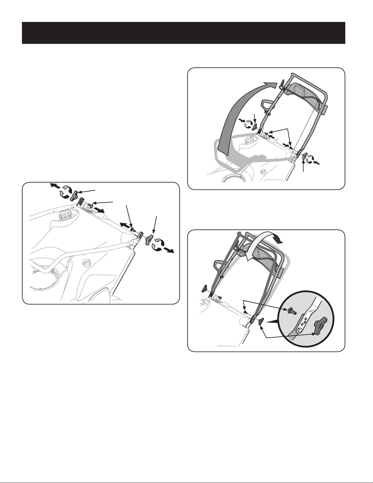
2. Pivot the upper handle into the operating position. Be sure not to pinch any
of the cables in the process. See Figure 2.
Wing
Knob
Carriage Bolts
Wing
Knob
Figure 2
3. The handle can be set in three different positions. Place the handle in the
desired position and then install wing knobs and carriage bolts in the
appropriate hole and secure the handle. See Figure 3.
Carriage Bolt
Wing
Knob
Figure 3
NOTE: All references to the left or right side of the snow thrower are from the
operator’s position. Any exceptions will be noted.
Unpacking the Snow Thrower
1. Open the top of the carton.
2. Cut down the corners on the front of the carton and fold down the front side.
3. Pull the snow thrower out of the carton. Be sure not to damage the chute,
chute rotation control assembly or any cables attached to the chute. Some
of these parts are shipped under the shroud on the backside of the carton.
Check for any cable ties securing the chute and remove if necessary.
Assembly
Positioning the Upper Handle
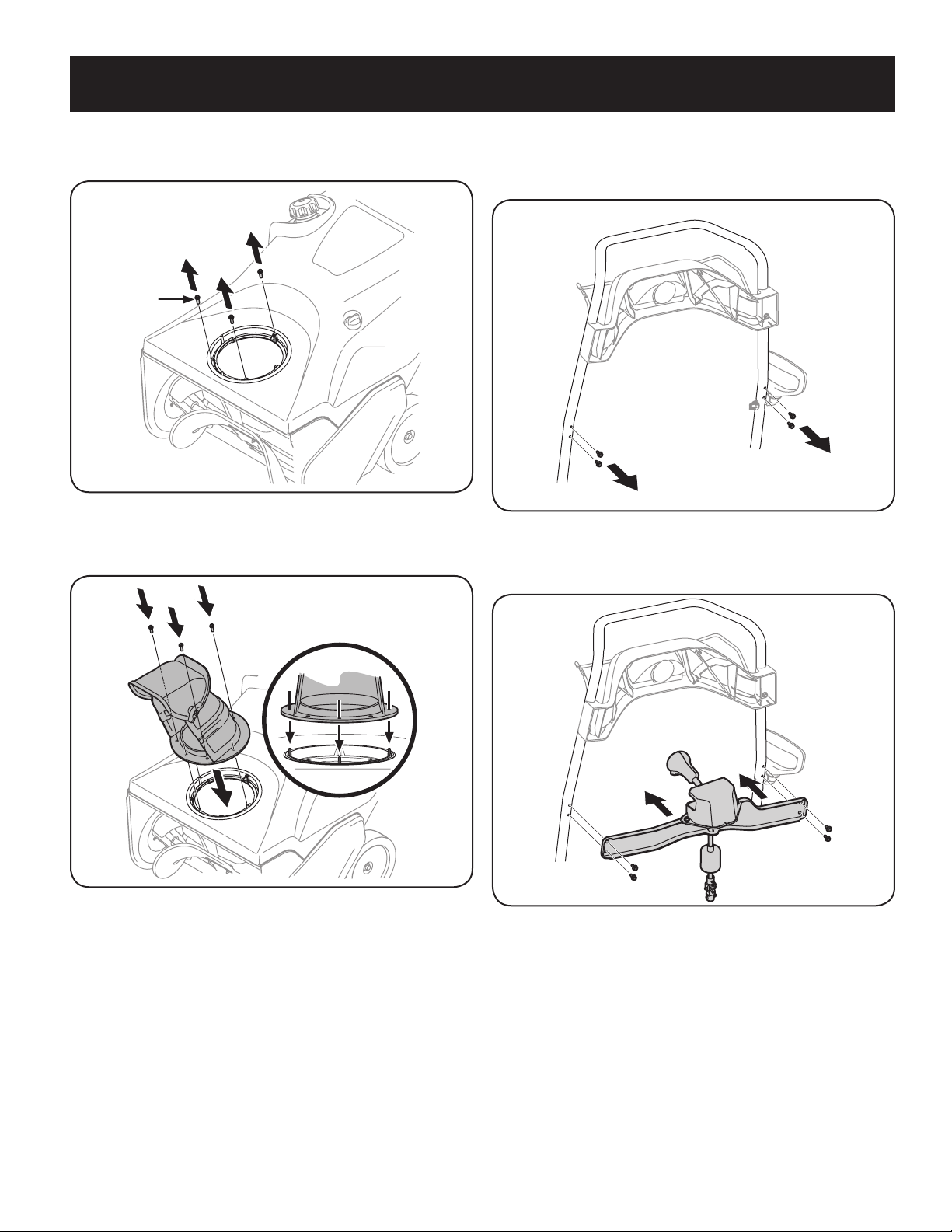
1. Remove the wing knob and carriage bolt from the top of the lower handle.
See Figure 1. It is not necessary to remove the shoulder screw and flange lock
nut below the wing knob and carriage bolt.
Wing Knob
Wing Knob
Carriage Bolts
Figure 1
8
ASSEMBLY
Installing the Chute Rotation Control Assembly
1. Remove the four hex washer screws from the back of the handle (two on
each side). See Figure 6.
Figure 6
2. Using the four hex washer screws, install the chute rotation control
assembly. See Figure 7.
Figure 7
Installing the Chute
1. Remove the hex washer screws in the chute base. See Figure 4.
Hex
Washer
Screw
Figure 4
2. Align the holes in the chute base with the holes in the lower chute and
secure with the previously removed hex washer screws. See Figure 5.
Figure 5
9
ASSEMBLY
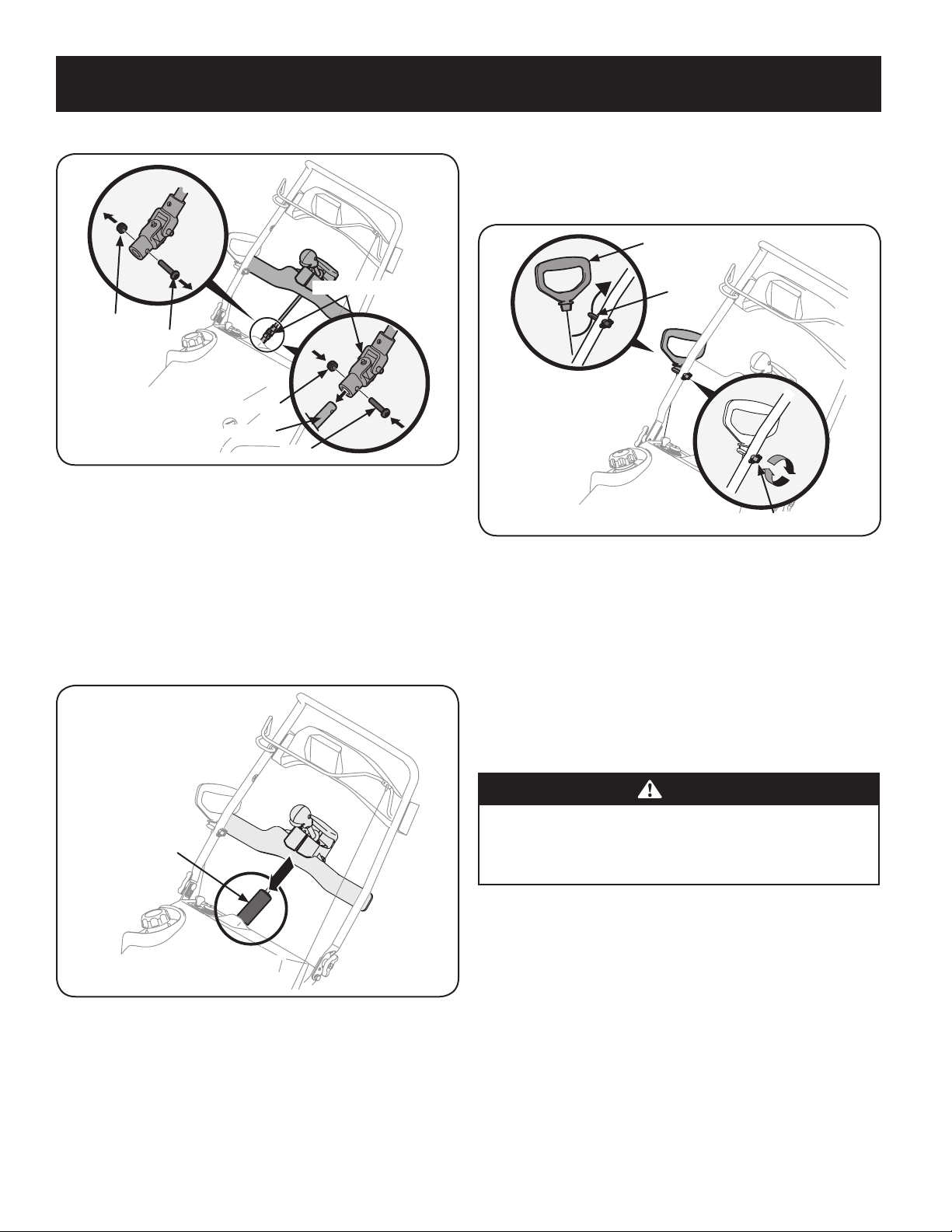
3. Remove the screw and hex lock nut from the universal joint. See Figure 8.
Hex Lock Nut
Screw
Universal Joint
Hex Lock Nut
Chute Rod
Screw
Figure 8
NOTE: Make sure the chute is facing forward when installing the universal joint.
4. Install the universal joint on the end of the chute rod as shown in Figure 8.
NOTE: Be sure the holes in the universal joint line up with the holes in the
chute rod. You may have to activate the chute rotation control trigger to
allow you to line up the holes.
5. Secure the universal joint with the hex nut and screw previously removed.
See Figure 8.
6. Slide the protective sleeve over the universal joint. See Figure 9.
Protective Sleeve
Figure 9
Installing the Recoil Starter Handle
1. Remove the eye bolt and handle knob from the manual bag.
2. Place the eye bolt and handle knob on the upper handle as shown in Figure
10. Do not fully tighten the hardware until instructed to do so.
Recoil Starter Handle
Eye Bolt
Handle Knob
Figure 10
NOTE: The opening of the eye bolt should face toward the back of the snow
thrower.
3. Slowly pull the recoil starter handle up towards the eye bolt.
4. Slip the recoil starter rope into the eye bolt from the back of the snow thrower.
See Figure 10.
5. Securely tighten the eye bolt and handle knob.
Set-Up
Fuel Recommendations
CAUTION
Operating the engine with E15 or E85 fuel, an oil/gasoline mixture, dirty
gasoline, or gasoline over 30 days old without fuel stabilizing additive
may result in damage to your engine’s carburetor. Subsequent damage
would not be covered under the manufacturer’s warranty.
Use automotive gasoline (unleaded or low leaded to minimize combustion chamber
deposits) with a minimum of 87 octane. Gasoline with up to 10% ethanol (E10)
or 15% MTBE (Methyl Tertiary Butyl Ether) can be used. Never use an oil/gasoline
mixture or dirty gasoline. Avoid getting dirt, dust, or water in the fuel tank. DO
NOT use E15 or E85 gasoline.
• Refuel in a well-ventilated area with the engine stopped. Do not smoke or
allow flames or sparks in the area where the engine is refueled or where
gasoline is stored.
• Do not overfill the fuel tank. After refueling, make sure the tank cap is closed
properly and securely.
• Be careful not to spill fuel when refueling. Spilled fuel or fuel vapor may
ignite. If any fuel is spilled, make sure the area is dry before starting the
engine.
• Avoid repeated or prolonged contact with skin or breathing of vapor.
10
ASSEMBLY
Adding Fuel
WARNING
Use extreme care when handling gasoline. Gasoline is extremely
flammable and the vapors are explosive. Never fuel the machine indoors or
while the engine is hot or running. Extinguish cigarettes, cigars, pipes and
other sources of ignition.
WARNING
Always keep hands and feet clear of equipment moving parts. Do not use a
pressurized starting fluid. Vapors are flammable.
1. Remove the gas cap, check the fuel level and add fuel if necessary. Fill the
tank until the fuel reaches 1/2” below the bottom of the filler neck to allow
for fuel expansion. Be careful not to overfill.
Checking & Adding Oil
CAUTION
The engine is shipped without oil in the engine. You must fill the engine
with SAE 5W-30 oil, shipped with your unit, before operating. Running
the engine with insufficient oil can cause serious engine damage and void
the product warranty.
1. Place the snow thrower on a flat, level surface.
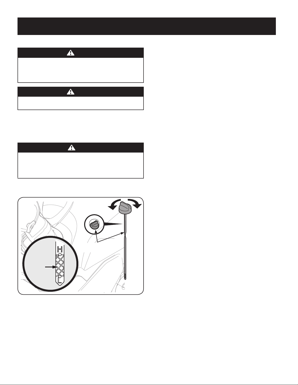
2. Remove the oil filler cap/dipstick and wipe the dipstick clean. See Figure 11.
Oil Filler Cap/
Dipstick
Fill
between
the high
and low
marks
Figure 11
3. Insert the oil filler cap/dipstick into the oil filler neck, but do not screw it in.
4. Remove the oil filler cap/dipstick. Slowly add oil into the reservoir until oil
level registers between high (H) and low (L), Figure 11.
5. Replace and tighten oil filler cap/dipstick firmly before starting engine.
NOTE: Do not overfill. Overfilling with oil may cause smoking, hard starting,
or spark plug fouling.
NOTE: DO NOT allow oil level to fall below the "L" mark on the dipstick.
Doing so may result in equipment malfunctions or damage.
NOTE:
To change the oil on your engine, see the Service and Maintenance
section of this manual.
11
OPERATION
Choke Control
RUN
CHOKE
RUN
CHOKE
CHOKE BELOW
Activating the choke control closes the choke plate on carburetor and aids in starting
engine. The choke lever slides between the RUN
and CHOKE positions.
Primer
Pressing the primer, making sure to cover the vent hole
when pushing, forces fuel directly into the engine’s
carburetor to aid in cold-weather starting.
Recoil Starter Handle
The recoil starter handle is used to start the engine.
Gas Cap
Remove the gas cap to add fuel.
Key
The key is a safety device. It must be fully inserted in order for the
engine to start. Remove the key when the snow thrower is not in use.
NOTE: Do not turn the key in an attempt to start the engine.
Doing so may cause it to break.
Auger
When engaged, the auger rotation draws snow into the auger housing and throws
it out the discharge chute. Rubber paddles on the auger also aid in propelling the
snow thrower as they come in contact with the pavement.
Meets ANSI Safety Standards
Craftsman Snow Throwers conform to the safety standard of the American National Standards Institute (ANSI).
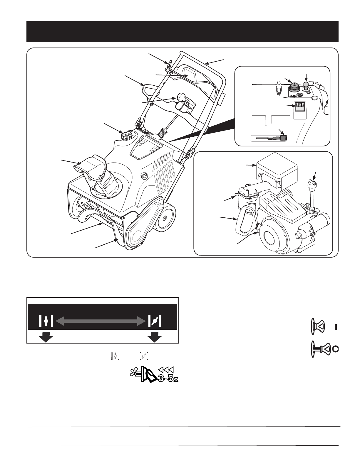
Chute Assembly
Shave Plate
Auger
Recoil Starter Handle
Gas Cap
Auger Control
Choke Lever
Primer
Key
Electric Starter Outlet
Electric Starter Button
Oil Fill/Dipstick
Muffler
Recoil Starter
Handle
Choke Lever
Oil Drain
Headlight
Chute Rotation Control
Upper Handle
Figure 1
Now that you have set up your snow thrower, it’s important to become acquainted
with its controls and features. Refer to Figure 1.
12
OPERATION
Auger Control
Located on the upper handle, the auger control handle is used to engage and disengage
drive to the auger. Squeeze the control handle against the upper handle to engage the
auger; release it to disengage.
Muffler
Engine exhaust exits the engine via the muffler.
Chute Rotation Control
The chute rotate control is located in the center of the control panel and controls the
direction snow is thrown. Depress the button and rotate the chute rotation control to the
right to turn the chute to the right and rotate to the left to turn the chute to the left.
Chute Assembly
The pitch of the discharge chute controls the angle at which the snow is thrown. Loosen
the wing knob on the side of the discharge chute before pivoting the discharge chute
upward or downward. Retighten the knob once the desired position has been achieved.
Shave Plate
The shave plate maintains contact with the pavement as the snow thrower is
propelled, allowing snow close to the pavement’s surface to be discharged.
Oil Fill/Dipstick
Engine oil level can be checked and oil added through the oil fill.
Oil Drain
Engine oil can be drained through the oil drain.
Headlight
The headlight is located on the upper center of the control panel and is on when the
snow thrower is running.
Electric Starter Outlet
Requires the use of a three-prong outdoor extension cord and a 120V power source/
wall outlet.
Electric Starter Button
Pressing the electric starter button engages the engine’s electric starter when plugged
into a 120V power source.
Before Starting the Engine
WARNING
Read, understand and follow all the instructions and warnings on the
machine and in this manual before operating.
Starting The Engine
WARNING
Always keep hands and feet clear of moving parts. Do not use a pressurized
starting fluid. Vapors are flammable.
WARNING
To avoid carbon monoxide poisoning, make sure the engine is outdoors in a
well-ventilated area.
1. Make certain the auger control is in the disengaged (released) position.
2. Insert ignition key into slot. Make sure it snaps into place. Do not attempt to
turn the key. See Figure 2.
Figure 2
NOTE: The engine cannot start unless the key is fully inserted into the
ignition switch.
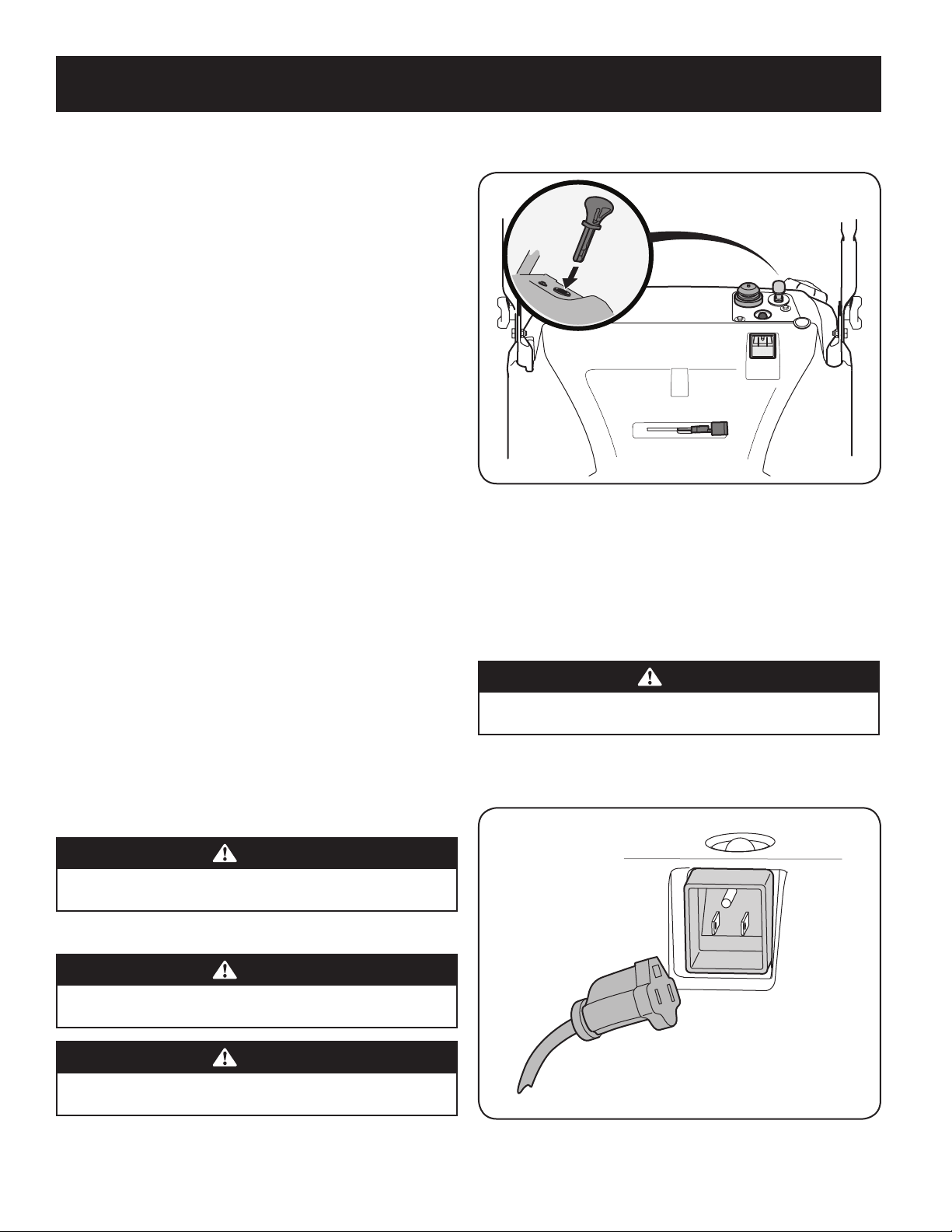
Electric Starter
Determine that your home’s wiring is a three-wire grounded system. Ask a licensed
electrician if you are not certain.
If you have a grounded three-prong receptacle, proceed as follows:
CAUTION
The extension cord can be any length, but must be rated for 15 amps at
125 volts, grounded and rated for outdoor use.
1. Plug the extension cord into the outlet located on the engine’s surface. Plug the
other end of extension cord into a three-prong 120-volt, grounded, AC outlet in a
w
ell-ventilated area See Figure 3.
Figure 3

13
OPERATION
2. Push the choke lever to the CHOKE position.
3. If the engine is warm, place the choke in the RUN position instead of
CHOKE .
4. Push the primer three (3) to five (5) times, making sure to cover the vent hole
when pushing.
5. If the engine is warm, push the primer button only once.
6. Push starter button to start engine.
7. Once the engine starts, release starter button.
8. Allow the engine to warm up several minutes, adjusting choke toward RUN
position. Wait until engine runs smoothly before each choke adjustment.
9. When disconnecting the extension cord, always unplug the end
at the three-prong wall outlet before unplugging the opposite end
from the snow thrower.
Recoil Starter
1. Push the choke lever to the CHOKE position.
2. If the engine is warm, place the choke in the RUN position instead of
CHOKE .
3. Push the primer three (3) to five (5) times, making sure to cover the vent
hole when pushing.
4. If the engine is warm, push the primer button only once.
Stopping the Engine
1. Run the engine for a few minutes without load before stopping to help dry
off any moisture on the engine.
WARNING
Muffler, engine and surrounding areas become hot and can cause a burn.
Be careful and do not touch when they are hot.
Engaging the Auger
Engage the auger by squeezing the auger control against the upper handle. Release
the control to stop the auger.
Engaging the Drive
Lift up slightly on the upper handle to allow the rubber paddles on the auger to
contact the pavement and propel the snow thrower forward. Pushing downward on
the handle will raise the auger off the ground and stop the forward motion.
NOTE: Excessive upward pressure on the handle will result in premature
wear to the rubber auger paddles, which will not be covered by the warranty.
Clearing a Clogged Discharge Chute
Hand contact with the rotating impeller inside the discharge chute is the most common
cause of injury associated with snow throwers. Never use your hand to clean out the
discharge chute.
To clear the chute:
1. Stop the engine. See instructions above for how to stop the engine.
2. Wait 10 seconds to be sure the impeller blades have stopped rotating.
3. Always use a clean-out tool or stick, not your hands.
2
. To stop the engine remove the key and store it in a safe place.
NOTE: Remove the key to quickly stop the engine in the event of an
emergency.
3
. Wipe all the snow and moisture away from the engine controls area.
Operating the Snow Thrower
• Once the auger drive is engaged, roll the snow thrower into the layer of snow
to be removed.
• Adjust the chute so that the snow is not thrown over other snow that is to be
removed.
• Prevent possible property d
amage or personal injury from object ricochet by
planning your snow throwing pattern to avoid discharge towards windows,
walls, cars, etc.
• Do not overload machine capacity by attempting to clear snow at too fast of a
rate.
• Never operate this machine without good visibility or light.
• Always be sure of your footing and keep a firm hold on the handles.
• Walk, never run when operating snow thrower.
• Look down and behind and use care when backing up.
WARNING
When pulling the starter rope, the rope can unexpectedly jerk back toward
the engine causing serious injury. To avoid this risk, carefully follow the
instructions below.
5
. Grasp the
recoil starter handle and slowly pull the rope out. At the point
where it becomes slightly harder to pull the rope, slowly allow the rope to
recoil.
6. Pull the starter handle with a firm, rapid stroke
.
Do not release the handle
and allow it to snap back. Keep a firm hold on the starter handle and allow
it to slowly recoil.
7. Allow the engine to warm up several minutes, adjusting choke toward
RUN position. Wait until engine runs smoothly before each choke
adjustment.
14
SERVICE AND MAINTENANCE
WARNING
Before performing any type of maintenance/service, disengage all controls
and stop the engine. Wait until all moving parts have come to a complete
stop. Disconnect spark plug wire and ground it against the engine to
prevent unintended starting. Always wear safety glasses during operation
or while performing any adjustments or repairs.
Follow the maintenance schedule given below. This chart describes service guidelines
only. Use the Service Log column to keep track of completed maintenance tasks. To
schedule service from Sears Parts & Repair, call 1-888-331-4569.
Interval Item Service Service Log
Each use 1. Engine oil level.
2. Snow thrower and exhaust area.
1. Check.
2. Clean.
1st 5 hours 1. Engine oil. 1. Change.
Every 5 hours 1. Engine oil.
2. Exhaust area.
1. Check.
2. Clean.
25 hours 1. Spark plug. 1. Check. (See engine manual)
Every season/50 hours 1. Engine oil. 1. Change.
Every season/100 hours 1. Spark plug. 1. Clean, replace, re-gap. (See engine
manual)
Every season/Before storage 1. Pivot points.
2. Control handle.
3. Extension spring.
1. Lubricate.
2. Lubricate.
3. Lubricate.
Maintenance
Engine
Refer to the Engine Operator’s Manual for all engine maintenance procedures.
Checking, adding and changing oil are also found in this manual.
Lubrication
Lubricate the pivot points on the control handle and the extension spring at the end
of the control cable with a light oil once every season and before the snow thrower
is put into storage at the end of the season.
Adjustments
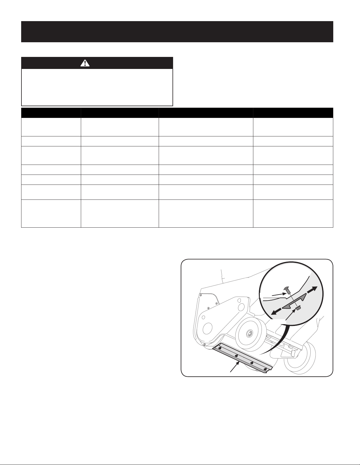
Shave Plate
To check the adjustment of the shave plate, place the machine on a level surface.
The wheels, shave plate and auger paddles should all contact the level surface.
Note that if the shave plate is adjusted too high, snow may blow under the auger
housing. If the shave plate wears out excessively, or the snow thrower does not
self-propel, the shave plate may be too low to the ground and needs to be adjusted.
NOTE: On new snow throwers or machines with a new shave plate installed, the
auger paddles may be slightly off the ground.
To adjust the shave plate proceed as follows:
1. Run the snow thrower until the fuel tank is empty.
2. Pull the starter cord until resistance is felt. Then tip the snow thrower back
until it rests on the handles. To ensure that the snow thrower does not tip
forward, it may be necessary to secure the handle to the ground with a block
or other object.
MAINTENANCE SCHEDULE
3. Loosen the four flange lock nuts and carriage screws which secure the shave
plate to the housing. See Figure 1. Move the shave plate to the appropriate
position and retighten the nuts and screws securely.
Side View
Lock Nut
Screw
Reversible Shave Plate
Figure 1
4. Tip the snow thrower back to the operating position and pull the recoil
starter handle a few times to see if it is difficult to pull.
1
5
SERVICE AND MAINTENANCE
5. If the starter is difficult to pull, remove the spark plug and pull the handle
several times to ensure that any oil trapped in the engine head is removed.
CAUTION
Oil may come out of the spark plug hole when it is removed and the starter
handle is pulled.
6. Inspect the spark plug. If it is wet, clean off any oil before re-installing.
Control Cable
As a result of both the control cable and the auger drive belt stretching due to
wear, periodic adjustments may be necessary. If the auger seems to hesitate when
rotating, proceed as follows:
1. The upper hole in the control handle provides for an adjustment in cable
tension. To adjust, disconnect the end of control cable from the bottom hole
in the control handle and reinsert it in the upper hole. Insert the cable from
the outside as shown in Figure 2.
Control Cable
Control Handle
Figure 2
2. Test the snow thrower to see if there is a noticeable difference. If after the
adjustment to the control cable the auger still hesitates when rotating, see
Auger Drive Belt Replacement for instructions on replacing the belt.
Chute Assembly
Refer to the Assembly section for instructions on adjusting the chute assembly.
Service
Auger Drive Belt Replacement
1. Run the snow thrower until the fuel tank is empty.
2. Pull the recoil starter handle until resistance is felt. Then tip the snow
thrower back until it rests on the handles.
3. Slide a board up through the auger and through the chute to secure the
auger in place.
4. Remove the belt cover by removing the two hex washer screws and one hex
lock screw that secure it to the frame. See Figure 3.
Hex Washer Screw
Hex Lock Screw
Figure 3
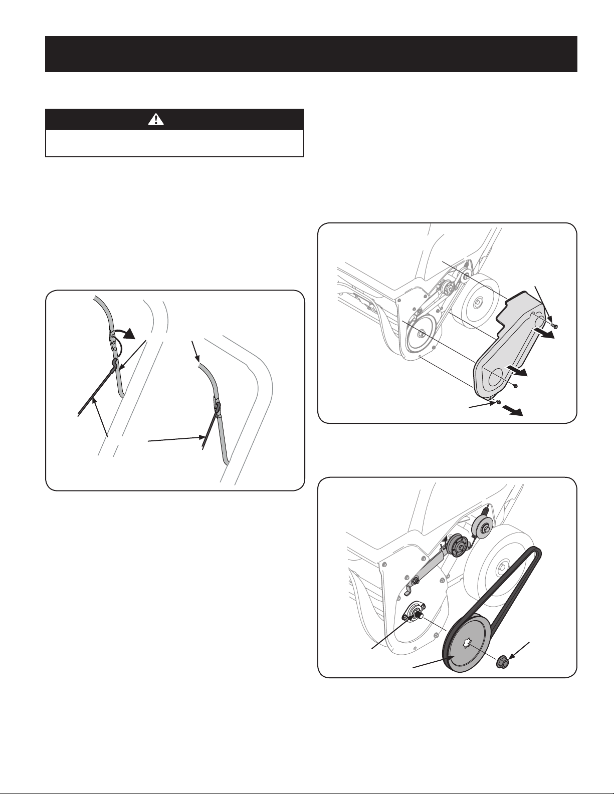
5. Remove the flange nut that secures the auger pulley to the auger shaft. See
Figure 4.
Flange Nut
Auger Pulley
Auger Shaft
Figure 4
6. Remove the auger pulley and the belt.
16
SERVICE AND MAINTENANCE
To replace the belt follow these instructions and refer to Figure 5:
Auger Pulley
Belt Keeper
Idler Pulley
Flange Nut
Drive Pulley
Figure 5
1. Route the belt around the drive pulley and under the idler pulley.
2. Route the end of the belt around the auger pulley and slide the pulley back
on to the auger shaft. It may be necessary to push down on the idler pulley
to get the auger pulley under the belt keeper.
3. Replace the flange nut and tighten securely.
4. Squeeze the auger control lever against the upper handle and reinstall the
belt cover removed earlier.
5. Remove the board from the auger and chute.
Replacing Auger Paddles
The snow thrower auger’s rubber paddles are subject to wear and should be
replaced if any signs of excessive wear are present.
CAUTION
Do NOT allow the auger’s rubber paddles to wear to the point where
portions of the metal auger itself can come in contact with the pavement.
Doing so can result in serious damage to your snow thrower.
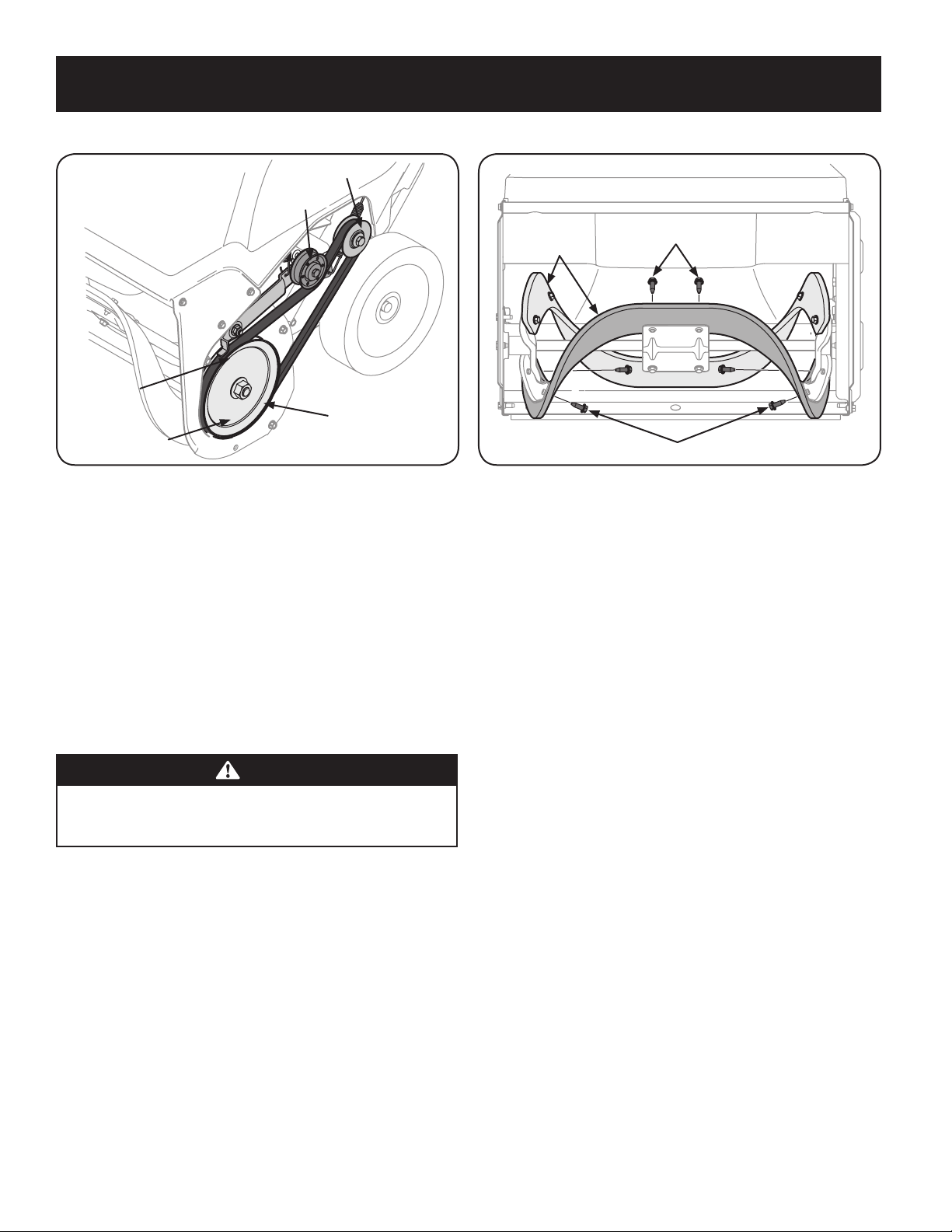
To change the rubber paddles, proceed as follows and refer to Figure 6:
Hex Washer Screw
Hex Washer Screw
Auger Paddle
Figure 6
1. Run the snow thrower until the fuel tank is empty.
2. Pull the recoil starter handle until resistance is felt. Then tip the snow
thrower back until it rests on the handles.
3. Remove the existing rubber paddles by unthreading the hex washer screws
which secure them to the auger. See Figure 6.
NOTE: The auger paddles should be replaced one at a time so that the
auger paddle still attached can be used as an example for positioning and
re-installing the new auger.
4. Secure the replacement rubber paddles to the auger using the hardware
removed earlier.
A full auger replacement kit including rubber paddles and hex washer screws may
be obtained through Sears Parts & Repair or by calling 1-888-331-4569. Ask for part
753-06469.
Reversing or Replacing Shave Plate
The shave plate is attached to the bottom of the auger housing and is subject to
wear. It should be checked periodically. There are two wearing edges and the shave
plate can be reversed.
1. Run the snow thrower until the fuel tank is empty.
2. Pull the recoil starter handle until resistance is felt. Then tip the snow
thrower back until it rests on the handles.
3. Remove the four carriage bolts and flange lock nuts which attach it to the
snow thrower housing. Refer to Figure 1 on page 12.
4. Reverse the existing shave plate or install a new one, making sure the new
shave plate and the heads of the carriage bolts are on the inside of the
housing.
5. Adjust the shave plate as instructed on page 12.
6. Tighten securely once adjusted.
A new shave plate may be obtained through Sears Parts & Repair or by calling
1-888-331-4569. Ask for part #731-07667.

1
7
SERVICE AND MAINTENANCE
Changing Engine Oil
WARNING
Shut off the engine and remove the ignition key before performing any
maintenance. To prevent accidental start-up, disconnect the spark plug boot.
Check oil level before each use and every 5 operating hours when the engine is
warm. Refer to Checking and Adding Oil in the Assembly Section.
Change the oil after the first 5 operating hours and every 50 operating hours
thereafter. Engine should still be warm but NOT hot from recent use.
1. Drain fuel from the tank by running the engine until the fuel tank is empty.
Be sure the fuel fill cap is secure.
2. Remove the three screws that secure the lower panel. Remove the lower
panel by lifting up on the panel to free the tabs at the bottom of the panel
from the tab slots and then pull back. See Figure 7.
Figure 7
NOTE: The bottom of the panel has tabs that help hold it in place.
NOTE: An oil drain extension kit is available separately. Visit a Sears Parts &
Repair Center or call 1-888-331-4569 and ask for kit #753-06684.
3. Place a suitable oil collection container under the oil drain plug.
4. Remove the oil drain plug, see Figure 8.
Oil Drain Plug
Figure 8
5. Tip the snow thrower back to drain oil into the container. Used oil must be
disposed of at a proper collection center.
6. Reinstall the drain plug and tighten it securely.
7. Refill with the recommended oil and check the oil level; refer to Checking
and Adding Oil in the Assembly Section.
8. Reinstall the oil filler cap/dipstick securely.
9. Re-install the lower panel by placing the tabs in the tab slots, lifting the
panel into place and secure with the three screws removed in step 2.
18
SERVICE AND MAINTENANCE
Off-Season Storage
Preparing the engine
Engines stored over 30 days need to be drained of fuel to prevent deterioration and
gum from forming in the fuel system or on essential carburetor parts. If the gasoline
in your engine deteriorates during storage, you may need to have the carburetor,
and other fuel system components, serviced or replaced.
1. Remove all fuel from the tank by running the engine until it stops.
2. Change the engine oil.
3. Remove the spark plug and pour approximately 1 oz. (30 ml) of clean engine
oil into the cylinder. Pull the recoil starter several times to distribute the oil,
and reinstall the spark plug.
4. Clean the exterior of the engine by discarding dirt and debris from the
following areas:
CAUTION
Do not spray the engine with water to clean it because the water could
contaminate the fuel. Using a garden hose or pressure washing equipment
can also force water into the muffler opening. Water that passes through
the muffler can enter the cylinder and cause damage.
• Cooling Fins
• Air Intake Screen or Recoil Starter/Flywheel Guard Areas
• Spark Plug Connection
• Levers
• Linkage Area
• Guards
• Carburetor
• Engine Head
5. Store in a clean, dry and well ventilated area away from any appliance
that operates with a flame or pilot light, such as a furnace, water heater or
clothes dryer. Avoid any area with a spark producing electric motor, or where
power tools are operated.
WARNING
Never store snow thrower with fuel in tank indoors or in poorly ventilated
areas, where fuel fumes may reach an open flame, spark or pilot light as on
a furnace, water heater, clothes dryer or gas appliance.
6. If possible, avoid storage areas with high humidity.
7. Keep the engine level in storage. Tilting the engine can cause fuel or oil
leakage.
Preparing snow thrower
If the snow thrower will not be used for 30 days or longer, follow the instructions
below.
1. Store the equipment in a clean, dry area.
2. Wipe down the snow thrower with a rag and remove any dirt or debris.
3. If storing the snow thrower in an unventilated area, rustproof the metal
parts of the machine with a light oil or silicone coating.

1
9
TROUBLESHOOTING
WARNING
Disconnect the spark plug wire and ground it against the engine to prevent
unintended starting. Before performing any type of maintenance/service,
disengage all controls and stop the engine. Wait until all moving parts
have come to a complete stop. Always wear safety glasses during operation
or while performing any adjustments or repairs.
This section addresses minor service issues. To locate the nearest Sears Service Center or to schedule service, call 1-888-331-4569.
Problem Cause Remedy
Engine fails to start 1. Fuel tank empty, or stale fuel.
2. Blocked fuel line.
3. Key not inserted all the way.
4. Spark plug wire disconnected.
5. Faulty spark plug.
6. Engine not primed.
7. Engine flooded from excessive priming.
1. Fill tank with clean fresh gasoline.
2. Contact a Sears Service Center.
3. Insert key all the way.
4. Connect wire to spark plug.
5. Clean spark plug, readjust gap, or replace.
6. Push the engine primer button three to five times.
7. Wait at least ten minutes before starting.
Engine running erratically/
inconsistent RPM (hunting or
surging)
1. Engine running on choke.
2. Fuel line blocked, or stale fuel.
3. Water or dirt in fuel system.
4. Carburetor out of adjustment.
5. Over-governed engine.
1. Move choke control to RUN position.
2. Contact a Sears Service Center.
3. Run engine until the fuel tank is empty. Refill with
fresh fuel.
4. Contact a Sears Service Center.
5. Contact a Sears Service Center.
Engine overheats
1. Carburetor out of adjustment. 1. Contact a Sears Service Center.
Loss of power
1. Spark plug wire loose.
2. Vent in gas cap plugged.
1. Firmly connect spark plug wire.
2. Clear vent.
Excessive vibration
1. Loose parts or damaged auger. 1. Stop engine immediately and remove key. Check for
possible damage. Tighten all bolts and nuts. Repair
as needed. If problem persists, take snow thrower to
a Sears Service Center.
Snow thrower fails to self-
propel
1. Auger control cable out of adjustment.
2. Auger drive belt loose or damaged.
1. Adjust auger control cable as shown in Service and
Maintenance section.
2. Replace auger drive belt.
Auger continues to rotate
1. Auger control cable out of adjustment. 1. Adjust auger control cable as shown in Service and
Maintenance section.
Unit fails to discharge snow
1. Chute assembly clogged.
2. Foreign object lodged in auger.
3. Auger control cable out of adjustment.
4. Auger belt loose or damaged.
1. Stop engine and disconnect spark plug wire. Clean
chute and inside of auger housing with clean-out
tool or stick.
2. Stop engine immediately and disconnect the spark
plug wire. Remove object from auger.
3. Adjust auger control cable.
4. Replace auger belt.

20
REPAIR PROTECTION AGREEMENT
Congratulations on making a smart purchase. Your new Craftsman® product is designed and manufactured for years of
dependable operation. But like all products, it may require repair from time to time. That’s when having a Repair Protection
Agreement can save you money and aggravation.
Here’s what the Repair Protection Agreement* includes:
Expert service by experienced service technicians trusted in millions of homes every year.
Unlimited service and no charge for parts and labor on all covered repairs.
Product replacement up to $1500 if your covered product can’t be fixed.
Discount of 25% from regular price of service and related installed parts not covered by the agreement.
Fast help by phone – phone support from a service agent on all products to help troubleshoot problems. Think of us as
a “talking owner’s manual.”
Once you purchase the Repair Protection Agreement, a simple phone call is all that it takes for you to schedule service. You
can call anytime day or night.
The Repair Protection Agreement is a risk-free purchase. If you cancel for any reason during the product warranty period,
we will provide a full refund. Or, a prorated refund anytime after the product warranty period expires. Purchase your Repair
Protection Agreement today!
Some limitations and exclusions apply. For prices and additional information call 1-800-827-6655.
Sears Installation Service
For Sears professional installation of home appliances, garage door openers, water heaters, and other major home items, call
1-888-331-4569.

(This page applicable in the U.S.A. and Canada only.)
Sears Brands Management Corporation (Sears), the California Air Resources Board (CARB)
and the United States Environmental Protection Agency (U.S. EPA)
Emission Control System Warranty Statement (Owner’s Defect Warranty Rights and Obligations)
EMISSION CONTROL WARRANTY COVERAGE IS APPLICABLE TO CERTIFIED ENGINES
PURCHASED IN CALIFORNIA IN 1995 AND THEREAFTER, WHICH ARE USED IN CALIFORNIA,
AND TO CERTIFIED MODEL YEAR 1997 AND LATER ENGINES WHICH ARE PURCHASED AND
USED ELSEWHERE IN THE UNITED STATES (AND AFTER JANUARY 1, 2001 IN CANADA).
California and United States Emission Control Defects Warranty Statement
The California Air Resources Board (CARB), U.S. EPA and Sears are pleased to explain the
Emission Control System Warranty on your model year 2000 and later small off-road
engine (SORE). In California, new small off-road engines must be designed, built and
equipped to meet the State’s stringent anti-smog standards. Elsewhere in the United
States, new non-road, spark-ignition engines certified for model year 1997 and later
must meet similar standards set forth by the U.S. EPA. Sears must warrant the emission
control system on your engine for the periods of time listed below, provided there has
been no abuse, neglect or improper maintenance of your small off-road engine. Your
emission control system includes parts such as the carburetor, air cleaner, ignition
system, muffler and catalytic converter. Also included may be connectors and other
emission related assemblies. Where a warrantable condition exists, Sears will repair
your small off-road engine at no cost to you including diagnosis, parts and labor.
Sears Emission Control Defects Warranty Coverage
Small off-road engines are warranted relative to emission control parts defects for a
period of one year, subject to provisions set forth below. If any covered part on your
engine is defective, the part will be repaired or replaced by Sears.
Owner’s Warranty Responsibilities
As the small off-road engine owner, you are responsible for the performance of the
required maintenance listed in your Operating and Maintenance Instructions. Sears
recommends that you retain all your receipts covering maintenance on your small
off-road engine, but Sears cannot deny warranty solely for the lack of receipts or for
your failure to ensure the performance of all scheduled maintenance. As the small
off-road engine owner, you should however be aware that Sears may deny you warranty
coverage if your small off-road engine or a part has failed due to abuse, neglect,
improper maintenance or unapproved modifications. You are responsible for presenting
your small off-road engine to an Authorized Sears Service Dealer as soon as a problem
exists. The undisputed warranty repairs should be completed in a reasonable amount
of time, not to exceed 30 days. If you have any questions regarding your warranty rights
and responsibilities, you should contact a Sears Service Representative at 1-800-469-
4663. The emission warranty is a defects warranty. Defects are judged on normal engine
performance. The warranty is not related to an in-use emission test.
Sears Emission Control Defects Warranty Provisions
The following are specific provisions relative to your Emission Control Defects Warranty
Coverage. It is in addition to the Sears engine warranty for non-regulated engines found
in the Operating and Maintenance Instructions.
1. Warranted Parts
Coverage under this warranty extends only to the parts listed below (the
emission control systems parts) to the extent these parts were present on the
engine purchased.
a. Fuel Metering System
• Cold start enrichment system
• Carburetor and internal parts
• Fuel Pump
b. Air Induction System
• Air cleaner
• Intake manifold
c. Ignition System
• Spark plug(s)
• Magneto ignition system
d. Catalyst System
• Catalytic converter
• Exhaust manifold
• Air injection system or pulse valve
e. Miscellaneous Items Used in Above Systems
• Vacuum, temperature, position, time sensitive valves and switches
• Connectors and assemblies
2. Length of Coverage
Sears warrants to the initial owner and each subsequent purchaser that the
Warranted Parts shall be free from defects in materials and workmanship which
caused the failure of the Warranted Parts for a period of one year from the date
the engine is delivered to a retail purchaser.
3. No Charge
Repair or replacement of any Warranted Part will be performed at no charge to
the owner, including diagnostic labor which leads to the determination that a
Warranted Part is defective, if the diagnostic work is performed at an Authorized
Sears Service Dealer. For emissions warranty service contact your nearest
Authorized Sears Service Dealer as listed in the “Yellow Pages” under “Engines,
Gasoline,” “Gasoline Engines,” “Lawn Mowers,” or similar category.
4. Claims and Coverage Exclusions
Warranty claims shall be filed in accordance with the provisions of the Sears
Engine Warranty Policy. Warranty coverage shall be excluded for failures of
Warranted Parts which are not original Sears parts or because of abuse, neglect
or improper maintenance as set forth in the Sears Engine Warranty Policy. Sears
is not liable to cover failures of Warranted Parts caused by the use of add-on,
non-original, or modified parts.
5. Maintenance
Any Warranted Part which is not scheduled for replacement as required
maintenance or which is scheduled only for regular inspection to the effect of
“repair or replace as necessary” shall be warranted as to defects for the warranty
period. Any Warranted Part which is scheduled for replacement as required
maintenance shall be warranted as to defects only for the period of time up
to the first scheduled replacement for that part. Any replacement part that is
equivalent in performance and durability may be used in the performance of
any maintenance or repairs. The owner is responsible for the performance of
all required maintenance, as defined in the Sears Operating and Maintenance
Instructions.
6. Consequential Coverage
Coverage hereunder shall extend to the failure of any engine components caused
by the failure of any Warranted Part still under warranty.
073808 Rev. A

FEDERAL and/or CALIFORNIA EMISSION CONTROL WARRANTY STATEMENT
YOUR WARRANTY RIGHTS AND OBLIGATIONS
MTD Consumer Group Inc, the United States Environmental Protection Agency (EPA), and for those products certified for sale in the state of
California, the California Air Resources Board (CARB) are pleased to explain the evaporative emission control system (ECS) warranty on your
2015-2016 small off-road equipment (outdoor equipment). In California, new outdoor equipment must be designed, built and equipped to
meet the State’s stringent anti-smog standards (in other states, outdoor equipment must be designed, built, and equipped to meet the U.S. EPA
small off-road spark ignition engine regulations). MTD Consumer Group Inc must warrant the ECS on your outdoor equipment for the period of
time listed below, provided there has been no abuse, neglect, or improper maintenance of the outdoor equipment.
Your ECS may include parts such as fuel tanks, fuel lines, fuel caps, valves, canisters, filters, vapor hoses, clamps, connectors, and other
associated emission-related components.
Where a warrantable condition exists, MTD Consumer Group Inc will repair your outdoor equipment at no cost to you including diagnosis,
parts, and labor.
MANUFACTURER’S WARRANTY COVERAGE:
This emission control system is warranted for two years. If any emission-related part on your outdoor equipment is defective, the part will be
repaired or replaced by MTD Consumer Group Inc.
OWNER’S WARRANTY RESPONSIBILITIES:
As the outdoor equipment owner, you are responsible for performance of the required maintenance listed in your owner’s manual. MTD
Consumer Group Inc recommends that you retain all receipts covering maintenance on your outdoor equipment, but MTD Consumer Group Inc
cannot deny warranty solely for the lack of receipts.
As the outdoor equipment owner, you should however be aware that MTD Consumer Group Inc may deny you warranty coverage if your
outdoor equipment or a part has failed due to abuse, neglect, improper maintenance, or unapproved modifications.
You are responsible for presenting your outdoor equipment to MTD Consumer Group Inc’s distribution center or service center as soon as
the problem exists. The warranty repairs should be completed in a reasonable amount of time, not to exceed 30 days. If you have a question
regarding your warranty coverage, you should contact the MTD Consumer Group Inc Service Department at 1-800-800-7310 or at
http://support.mtdproducts.com.
GENERAL EMISSIONS WARRANTY COVERAGE:
MTD Consumer Group Inc warrants to the ultimate purchaser and each subsequent purchaser that the outdoor equipment is: (1) designed,
built, and equipped so as to conform with all applicable regulations; and (2) free from defects in materials and workmanship that cause the
failure of a warranted part for a period of two years.
The warranty period begins on the date the outdoor equipment is delivered to an ultimate purchaser or first placed into service.
Subject to certain conditions and exclusions as stated below, the warranty on emission-related parts is as follows:
1. Any warranted part that is not scheduled for replacement as required maintenance in the written instructions supplied is warranted for
the warranty period stated above. If the part fails during the period of warranty coverage, the part will be repaired or replaced by MTD
Consumer Group Inc according to subsection (4) below. Any such part repaired or replaced under warranty will be warranted for the
remainder of the period.
2. Any warranted part that is scheduled only for regular inspection in the written instructions supplied is warranted for the warranty period
stated above. Any such part repaired or replaced under warranty will be warranted for the remaining warranty period.
3. Any warranted part that is scheduled for replacement as required maintenance in the written instructions supplied is warranted for the
period of time before the first scheduled replacement date for that part. If the part fails before the first scheduled replacement, the part
will be repaired or replaced by MTD Consumer Group Inc according to subsection (4) below. Any such part repaired or replaced under
warranty will be warranted for the remainder of the period prior to the first scheduled replacement point for the part.
4. Repair or replacement of any warranted part under the warranty provisions herein must be performed at a warranty station at no charge
to the owner.
5. Notwithstanding the provisions herein, warranty services or repairs will be provided at all of our distribution centers that are franchised to
service the subject engines or equipment.
6. The outdoor equipment owner will not be charged for diagnostic labor that is directly associated with diagnosis of a defective, emission-
related warranted part, provided that such diagnostic work is performed at a warranty station.
7. MTD Consumer Group Inc is liable for damages to other engine or equipment components proximately caused by a failure under
warranty of any warranted part.
8. Throughout the off-road engine and equipment warranty period stated above, MTD Consumer Group Inc will maintain a supply of
warranted parts sufficient to meet the expected demand for such parts.
9. Any replacement part may be used in the performance of any warranty maintenance or repairs and must be provided without charge to
the owner. Such use will not reduce the warranty obligations of MTD Consumer Group Inc.
10. Add-on or modified parts that are not exempted by the Air Resources Board may not be used. The use of any non-exempted add-on or
modified parts by the ultimate purchaser will be grounds for disallowing a warranty claim. MTD Consumer Group Inc will not be liable to
warrant failures of warranted parts caused by the use of a non-exempted add-on or modified part.

063015 Rev. C
WARRANTED PARTS:
The repair or replacement of any warranted part otherwise eligible for warranty coverage may be excluded from such warranty coverage
if MTD Consumer Group Inc demonstrates that the outdoor equipment has been abused, neglected, or improperly maintained, and that
such abuse, neglect, or improper maintenance was the direct cause of the need for repair or replacement of the part. That notwithstanding,
any adjustment of a component that has a factory installed, and properly operating, adjustment limiting device is still eligible for warranty
coverage. Further, the coverage under this warranty extends only to parts that were present on the off-road equipment purchased.
The following emission warranty parts are covered (if applicable):
1. Fuel Metering System
• Fuel pump
• Fuel tank
2. Evaporative Control
• Fuel hose
• Fuel hose clamps
• Tethered fuel cap
• Carbon canister
• Vapor lines

23
ÍNDICE
© Sears Brands, LLC
DECLARACIÓN DE GARANTÍA
N.º DE MODELOESPECIFICACIONES DEL PRODUCTO
Declaración de garantía ..............................24
Medidas de seguridad
................................25
Desembalaje y montaje
..............................29
Funcionamiento
.....................................33
Servicio y Mantenimiento
............................36
Almacenamiento fuera de temporada
................40
Solución de problemas
...............................41
Acuerdo de protección para reparaciones
.............43
Números de servicio
........................Contratapa
CRAFTSMAN GARANTÍA LIMITADA
Durante dos años desde la fecha de venta, este producto está garantizado contra defectos de materiales o mano de obra.
CON EL COMPROBANTE DE VENTA, un producto defectuoso recibirá la reparación o sustitución gratuita, a opción del vendedor.
Para detalles de la cobertura de garantía para obtener la reparación o sustitución gratuita, visite la página web: www.craftsman.com/warranty
Esta garantía cubre únicamente defectos de material y mano de obra. La cobertura de garantía no incluye:
• Componentes desechables que pueden gastarse por el uso normal dentro del periodo de garantía, incluyendo pero no limitado a, sinfines, paletas de
barrena, cortadores de deriva, zapatas antideslizantes, afeitarse plato, pasadores de seguridad, bujías, filtro de aire, correas y filtros de aceite.
• Servicio de mantenimiento estándar, cambios de aceite o puestas a punto.
• El reemplazo o la reparación de neumáticos causada por pinchazos con objetos externos, como clavos, espinas, tocones o vidrio.
• Tire o rueda de repuesto o reparación resultantes del desgaste normal, accidente u operación o mantenimiento inadecuados.
• Reparaciones necesarias debido al abuso del operador, incluyendo pero no limitado a los daños causados por el exceso de velocidad del motor, o del
impacto de objetos que tuerzan el marco, eje de la barrena, etc.
• Las reparaciones necesarias debido a la negligencia del operador, incluyendo pero no limitado a, daños eléctricos y mecánicos causados por el
almacenamiento inadecuado, falta de uso del grado y la cantidad de aceite de motor, o por no mantener el equipo de acuerdo con las instrucciones
contenidas en el manual del operador.
• Motor (sistema de combustible) de limpieza o reparaciones causadas por combustible determinados a ser contaminado u oxidado (viejo). En general, el
combustible debe usarse dentro de los 30 días siguientes a su fecha de compra.
• Deterioro y desgaste normales de las terminaciones exteriores, o reemplazo de las etiquetas del producto.
Esta garantía no es válida si el producto se utiliza nunca, mientras que la prestación de servicios comerciales o si se alquila a otra persona.
Esta garantía le otorga derechos legales específicos, y usted también puede tener otros derechos que varían de un estado a otro.
Sears Brands Management Corporation, Hoffman Estates, IL 60179
Tipo de aceite del motor: SAE 5W-30
Gasolina: Gasolina sin plomo
Número de modelo _____________________________
Número de serie ________________________________
Fecha de compra _______________________________
Registre arriba el número del modelo, el número
de serie y la fecha de compra
25
INSTRUCCIONES DE SEGURIDAD
CAPACITACIÓN
• Lea, entienda y cumpla todas las instrucciones incluidas en la máquina y
en el(los) manual(es) antes de intentar realizar el montaje de la unidad y
utilizarla. Si no lo hace, se pueden provocar lesiones personales al operador
o a los transeúntes. Guarde este manual en un lugar seguro para consultas
futuras y periódicas, así como para solicitar repuestos. Ante cualquier duda,
llame al 1-800-4MY-HOME.
• Familiarícese con todos los controles y con el uso adecuado de
los mismos. Sepa cómo detener la máquina y desenganchar los controles
rápidamente.
• No permita nunca que los niños menores de 14 años utilicen esta máquina.
Los niños de 14 años en adelante deben leer y entender las instrucciones de
operación y normas de seguridad contenidas en este manual y en la máquina
y deben ser entrenados y supervisados por un adulto.
• Nunca permita que los adultos operen esta máquina sin recibir antes la
instrucción apropiada.
• Los objetos arrojados por la máquina pueden causar lesiones graves.
Planifique el patrón en el que va a ir arrojando nieve para evitar que
la descarga de material se realice hacia los caminos,
los observadores, etc.
• Mantenga a los observadores, mascotas y niños por lo menos a 75 pies de la
máquina siempre que esté funcionando. Detenga la máquina si alguien se
acerca.
• Sea precavido para evitar patinarse o caerse especialmente cuando opera la
máquina en marcha atrás.
PREPARATIVOS
• Inspeccione minuciosamente el área donde utilizará el equipo. Saque todos
los felpudos, periódicos, trineos, tablas, cables y otros objetos extraños con
los que podría tropezar o que podrían ser arrojados por la barrena/impulsor.
• Para protegerse los ojos utilice siempre anteojos o antiparras de seguridad
mientras opera la máquina o mientras la ajusta o repara. Los objetos
arrojados que rebotan pueden causar lesiones oculares graves.
• No opere la máquina sin la vestimenta adecuada para estar al aire libre en
invierno. No utilice alhajas, bufandas largas u otras prendas sueltas que
podrían enredarse en las partes móviles. Utilice un calzado especial para
superficies resbaladizas.
• Use un prolongador y un tomacorriente de tres cables con conexión a tierra
para todas las máquinas con motores de encendido eléctrico.
• Desengrane todas las palancas de control antes de arrancar el motor.
• Nunca intente realizar ajustes mientras el motor está en marcha excepto en
los casos específicamente recomendados en el manual del operador.
• Deje que el motor y la máquina se adapten a la temperatura exterior antes
de comenzar a sacar la nieve.
ADVERTENCIA
Su Responsabilidad — Esta máquina motorizada sólo pueden
usarla las personas que lean, comprendan y respeten las advertencias e
instrucciones que aparecen en este manual y en la máquina.
¡GUARDE ESTAS INSTRUCCIONES!
ADVERTENCIA
La presencia de este símbolo indica que se trata de instrucciones de
seguridad importantes que debe respetar para evitar poner en riesgo su
seguridad personal y/o material y la de los demás. Lea y cumpla todas las
instrucciones de este manual antes de intentar operar esta máquina. Si no
respeta estas instrucciones puede provocar lesiones personales. Cuando
vea este símbolo, ¡TENGA EN CUENTA LA ADVERTENCIA!
PELIGRO
Esta máquina está diseñada para ser utilizada respetando las normas de
seguridad contenidas en este manual. Al igual que con cualquier tipo de
equipo motorizado, un descuido o error por parte del operador puede
producir lesiones graves. Esta máquina es capaz de amputar dedos, manos
y pies y de arrojar residuos. De no respetar las instrucciones de seguridad
siguientes se pueden producir lesiones graves o la muerte.
ADVERTENCIA
PROPOSICIÓN 65 DE CALIFORNIA
El escape del motor de este producto, algunos de sus componentes y
algunos componentes del vehículo contienen o liberan sustancias químicas
que el estado de California considera que pueden producir cáncer, defectos
de nacimiento u otros problemas reproductivos.

26
INSTRUCCIONES DE SEGURIDAD
Manejo seguro de la gasolina:
Para evitar lesiones personales o daños materiales sea sumamente cuidadoso al
manipular la gasolina. La gasolina es sumamente inflamable y sus vapores pueden causar
explosiones. Si se derrama gasolina encima o sobre la ropa se puede lesionar gravemente
ya que se puede encender. Lávese la piel y cámbiese de ropa de inmediato.
• Utilice sólo los recipientes para gasolina autorizados.
• Apague todos los cigarrillos, cigarros, pipas y otras fuentes de combustión.
• Nunca cargue combustible en la máquina en un espacio cerrado.
• Nunca saque la tapa del combustible ni agregue combustible mientras el
motor está caliente o en marcha.
• Deje que el motor se enfríe por lo menos dos minutos antes de volver a
cargar combustible.
• Nunca llene en exceso el depósito de combustible. Llene el tanque a no más
de ½ pulgada por debajo de la base del cuello de llenado dejando espacio
para la dilatación del combustible.
• Vuelva a colocar la tapa del combustible y ajústela bien.
• Limpie el combustible que se haya derramado sobre el motor y el equipo.
Traslade la máquina a otra zona. Espere 5 minutos antes de encender el motor.
• Nunca almacene la máquina o el recipiente de combustible en un espacio
cerrado donde haya fuego, chispas o luz piloto (por ejemplo, hornos,
calentadores de agua, calefactores, secadores de ropa, etc.).
• Deje que la máquina se enfríe por lo menos 5 minutos antes de guardarla.
• Nunca llene los recipientes en el interior de un vehículo o camión o caja de
remolque con recubrimiento plástico. Coloque siempre los recipientes en el
piso y lejos del vehículo antes de llenarlos.
• Si es posible, retire el equipo a gasolina del camión o remolque y llénelo en el
suelo. Si esto no es posible, llene el equipo en un remolque con un recipiente
portátil, en vez de hacerlo con una boquilla dispensadora de gasolina.
• Mantenga la boquilla de llenado en contacto con el borde del depósito
de combustible o con la abertura del recipiente en todo momento, hasta
terminar la carga. No utilice un dispositivo de boquilla de apertura/cierre.
FUNCIONAMIENTO
• No ponga las manos o los pies cerca de las piezas giratorias, en la caja de la
barrena / impulsor o en el montaje del canal de descarga. El contacto con las
piezas giratorias puede resultar en la amputación de manos o pies.
• La palanca de control de la barrena / impulsor es un dispositivo de seguridad.
Nunca evite su funcionamiento. De hacerlo la operación de la máquina es
riesgosa y puede ocasionar lesiones.
• Las palancas de control deben funcionar bien en ambas direcciones y
regresar automáticamente a la posición de desengrane cuando se las suelta.
• Nunca opere la máquina si falta un montaje del canal o si el mismo está dañado.
Mantenga todos los dispositivos de seguridad en su lugar y en funcionamiento.
• Nunca encienda el motor en espacios cerrados o en una zona con poca
ventilación. El escape del motor contiene monóxido de carbono, un gas
inodoro y letal.
• No utilice la máquina bajo la influencia del alcohol o las drogas.
• El silenciador y el motor se calientan y pueden causar quemaduras.
No los toque. Mantenga a los niños alejados.
• Sea sumamente precavido cuando opere la máquina sobre una superficie
con grava o cuando la cruce. Manténgase alerta por si se presentan peligros
ocultos o tránsito.
• Tenga cuidado cuando cambie de dirección o cuando opere la máquina en
pendientes.
• Planifique el patrón en el que va a ir arrojando nieve para evitar que la
descarga de material se produzca hacia las ventanas, las paredes, los
automóviles, etc. y evitar así posibles daños materiales o lesiones producidas
por los rebotes.
• Nunca dirija la descarga hacia los niños, los observadores o las mascotas ni
deje que nadie se pare delante de la máquina.
• No sobrecargue la capacidad de la máquina tratando de sacar la nieve muy
rápidamente.
• Nunca opere esta máquina sin buena visibilidad o iluminación. Siempre debe
estar seguro de que está bien afirmado y sujetando firmemente las manijas.
Camine, nunca corra.
• Corte la corriente a la barrena/impulsor cuando transporte la máquina
o cuando la misma no está en uso.
• Nunca opere la máquina a alta velocidad de desplazamiento sobre
superficies resbaladizas. Mire hacia abajo y hacia atrás y tenga cuidado
cuando vaya marcha atrás.
• Si la máquina comenzara a vibrar de manera anormal, detenga el motor,
desconecte el cable de la bujía y póngala de manera que haga masa contra
el motor. Inspeccione la máquina minuciosamente para ver si está dañada.
Repare todos los daños antes de encender y operar la máquina.
• Desengrane todas las palancas de control y detenga el motor antes de dejar
la posición de operación (detrás de las manijas). Espere a que la barrena/
impulsor se detenga por completo antes de destapar el montaje del canal o
realizar ajustes e inspecciones.
• Nunca ponga las manos en las aberturas de descarga o de recolección. No
destape el montaje del canal mientras el motor está en funcionamiento.
Antes de destaparlo, apague el motor y permanezca detrás de las barras de
control hasta que todas las partes móviles se hayan detenido.
• Use sólo uniones y accesorios aprobados por el fabricante (por ejemplo,
pesas para las ruedas, cadenas para los neumáticos, cabinas, etc.).
• Para encender el motor, jale de la cuerda lentamente hasta que sienta
resistencia, luego jale rápidamente. El repliegue rápido de la cuerda de
arranque (tensión de retroceso) le jalará la mano y el brazo hacia el motor
más rápido de lo que usted puede soltar. Puede llegar a causar huesos rotos,
fracturas, hematomas y esguinces.
• Llame al 1-800-4MY-HOME para la ubicación más cercana de Sears Parts &
Service Center de reparación.
DESPEJE DE UN CANAL DE DESCARGA OBSTRUIDO
El contacto de las manos con el impulsor rotatorio que está dentro del canal de
descarga es la causa más común de lesiones asociadas con las máquinas quitanieve.
Nunca use su mano para limpiar el canal de descarga.
Para despejar el canal:
1. ¡APAGUE EL MOTOR!
2. Espere 10 segundos para estar seguro de que las cuchillas del motor han
dejado de rotar.
3. Utilice siempre una herramienta de limpieza, no use las manos.

27
INSTRUCCIONES DE SEGURIDAD
INSTRUCCIONES DE SEGURIDAD
MANTENIMIENTO Y ALMACENAMIENTO
• Nunca altere los dispositivos de seguridad. Controle periódicamente que
funcionen correctamente. Remítase a las secciones de mantenimiento y
ajuste de este manual.
• Antes de realizar la limpieza, reparar o revisar la máquina, desengrane todas
las palancas de control y detenga el motor. Espere a que la barrena/impulsor
se detenga por completo. Desconecte el cable de la bujía y póngalo haciendo
masa contra el motor para evitar que se encienda accidentalmente.
• Controle frecuentemente que todos los pernos y tornillos estén bien
ajustados para comprobar que la máquina se encuentra en condiciones
seguras de funcionamiento. Además, haga una inspección visual de la
máquina para verificar si está dañada.
• No cambie la configuración del regulador del motor ni acelere demasiado
el mismo. El regulador del motor controla la velocidad máxima de
funcionamiento seguro del motor.
• Quitanieves afeitar placas y patines están sujetos a desgaste y daños. Para su
protección de seguridad, verifique frecuentemente todos los componentes y
con (OEM) del fabricante del equipo original sólo aparece en las páginas de
piezas de este manual del operador. El uso de piezas que no cumplen con las
especificaciones del equipo original puede conducir a la mala ejecución y la
seguridad de compromiso!
• Revise las palancas de control periódicamente para verificar que engranen y
desengranen adecuadamente y ajústelos si es necesario. Consulte la sección
de ajustes en este manual del operador para obtener instrucciones.
• Mantenga o reemplace las etiquetas de seguridad y de instrucciones según
sea necesario.
• Observe la reglamentación y las normas respecto a la eliminación correcta de
gasolina, aceite, etc. para proteger el medio ambiente.
• Antes de almacenar la máquina enciéndala unos minutos para sacar la nieve
que haya quedado en la misma y para evitar así que se congele la barrena/
impulsor.
• Nunca almacene la máquina o el recipiente de combustible en un espacio
cerrado donde haya fuego, chispas o luz piloto como por ejemplo,
calentadores de agua, hornos, secadores de ropa, etc.
• Consulte siempre el manual del operador para obtener instrucciones
adecuadas para el almacenamiento fuera de temporada.
• Verifique frecuentemente la línea de combustible, el depósito, el tapón, y los
accesorios buscando rajaduras o pérdidas. Reemplace de ser necesario.
• No dé arranque al motor si no está la bujía de encendido.
• Según la Comisión de Seguridad de Productos para el Consumidor de los
Estados Unidos (CPSC) y la Agencia de Protección Ambiental de los Estados
Unidos (EPA), este producto tiene una vida útil media de siete (7) años o 60
horas de funcionamiento. Al finalizar la vida útil media haga inspeccionar
anualmente esta unidad por un distribuidor de servicio autorizado para
cerciorarse de que todos los sistemas mecánicos y de seguridad funcionan
correctamente y no tienen excesivo desgaste. Si no lo hace, pueden
producirse accidentes, lesiones o la muerte.
NO MODIFIQUE EL MOTOR
Para evitar lesiones graves o la muerte, no modifique el motor de ninguna manera.
Si altera la configuración del regulador, el motor se puede desbocar y funcionar
a velocidades que no son seguras. Nunca cambie la configuración de fábrica del
regulador del motor.
AVISO REFERIDO A EMISIONES
Los motores que están certificados y cumplen con las regulaciones de emisiones
federales EPA y de California para SORE (Equipos pequeños todo terreno) están
certificados para funcionar con gasolina sin plomo común y pueden incluir
los siguientes sistemas de control de emisiones: Modificación de motor (EM),
catalizador oxidante (OC), inyección de aire secundaria (SAI) y catalizador de tres
vías (TWC) si están instalados.
AMORTIGUADOR DE CHISPAS
ADVERTENCIA
Esta máquina está equipada con un motor de combustión interno y no debe
ser utilizada en o cerca de un terreno agreste cubierto por bosque, malezas
o hierba excepto que el sistema de escape del motor esté equipado con
un amortiguador de chispas que cumpla con las leyes locales o estatales
correspondientes (en caso de existir)
Si se utiliza un amortiguador de chispas el operador lo debe mantener en
condiciones de uso adecuadas. En el Estado de California las medidas anteriormente
mencionadas son exigidas por ley (Artículo 4442 del Código de Recursos Públicos
de California). Es posible que existan leyes similares en otros estados. Las leyes
federales se aplican en territorios federales. Podrá obtener un amortiguador de
chispas para el silenciador en el centro de servicio de piezas y reparaciones Sears
más cercano.

28
INSTRUCCIONES DE SEGURIDAD
SÍMBOLOS DE SEGURIDAD
En esta página se presentan y describen los símbolos de seguridad que pueden aparecer en este producto. Lea, entienda y cumpla todas las instrucciones
incluidas en la máquina antes de intentar realizar el montaje de la unidad y utilizarla.
Símbolo Descripción
LEA LOS MANUALES DEL OPERADOR
Lea, entienda y cumpla todas las instrucciones incluidas en los manuales antes de realizar el montaje
de la unidad y utilizarla.
ADVERTENCIA — CUCHILLAS GIRATORIAS
Mientras la máquina está en funcionamiento mantenga las manos lejos de las aberturas de entrada
y de descarga. En el interior hay cuchillas giratorias.
ADVERTENCIA — CUCHILLAS GIRATORIAS
Mientras la máquina está en funcionamiento mantenga las manos lejos de las aberturas de entrada
y de descarga. En el interior hay cuchillas giratorias.
ADVERTENCIA — BARRENA GIRATORIA
No ponga las manos o los pies cerca de las piezas giratorias, en la caja de la barrena / impulsor o en el
montaje del canal de descarga. El contacto con las piezas giratorias puede resultar en la amputación
de manos o pies.
ADVERTENCIA — ARROJA OBJETOS
Esta máquina puede levantar y arrojar objetos lo cual puede causar lesiones personales graves.
ADVERTENCIA — LA GASOLINA ES INFLAMABLE
Deje que el motor se enfríe por lo menos dos minutos antes de volver a cargar combustible.
ADVERTENCIA — MONÓXIDO DE CARBONO
Nunca encienda el motor en espacios cerrados o en una zona con poca ventilación. El escape del
motor contiene monóxido de carbono, un gas inodoro y letal.
ADVERTENCIA — DESCARGAS ELÉCTRICAS
No use el arranque eléctrico del motor bajo la lluvia.
ADVERTENCIA — SUPERFICIE CALIENTE
Las piezas del motor, especialmente el silenciador, se recalientan durante la operación. Deje que
el motor y el silenciador se enfríen antes de tocarlos.
INSTRUCCIONES DE SEGURIDAD
¡ADVERTENCIA! Su responsabilidad — Restrinja el uso de esta máquina motorizada a las personas que lean,
comprendan y respeten las advertencias e instrucciones de este manual y en la máquina.
¡GUARDE ESTAS INSTRUCCIONES!
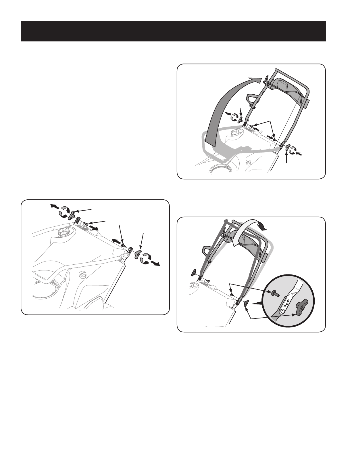
29
MONTAJE
2. Gire la manija superior a la posición de funcionamiento. Asegúrese de no
apretar los cables en el proceso. Vea la Figura 2.
Perilla
de aletas
Pernos de carro
Perilla
de aletas
Figura 2
3. La manija se puede ajustar en tres posiciones diferentes. Ubique la manija en
la posición deseada y luego instale las perillas de aletas y los pernos de carro
en el orificio adecuado y sujete la manija. Vea la Figura 3.
Pernos de carro
Perilla
de aletas
Figura 3
NOTA: Todas las referencias a los lados derecho o izquierdo de la máquina
quitanieve se hacen observando la misma desde la posición del operador. En caso de
que hubiese una excepción, se especificará claramente.
Cómo Desembalar La Máquina Quitanieve
1. Abra la parte de arriba de la caja.
2. Corte las esquinas del frente de la caja y doble hacia abajo
el frente.
3. Saque la máquina quitanieve de la caja. Asegúrese de no dañar el canal, el
montaje del control de rotación del canal ni los cables que están conectados
al canal. Algunas de estas piezas se envían debajo de la cubierta en la parte
posterior de la caja. Controle si hay precintos sujetando el canal y retírelos si
es necesario.
Montaje
Colocación de la manija superior
1. Extraiga las perillas de aletas y el perno de carro de la parte de arriba de
la manija inferior. Vea la Figura 1. No es necesario extraer el tornillo con
reborde y la tuerca de seguridad con brida que están debajo de la perilla de
aletas y el perno de carro.
Perilla de aletas
Perilla de aletas
Pernos de carro
Figura 1
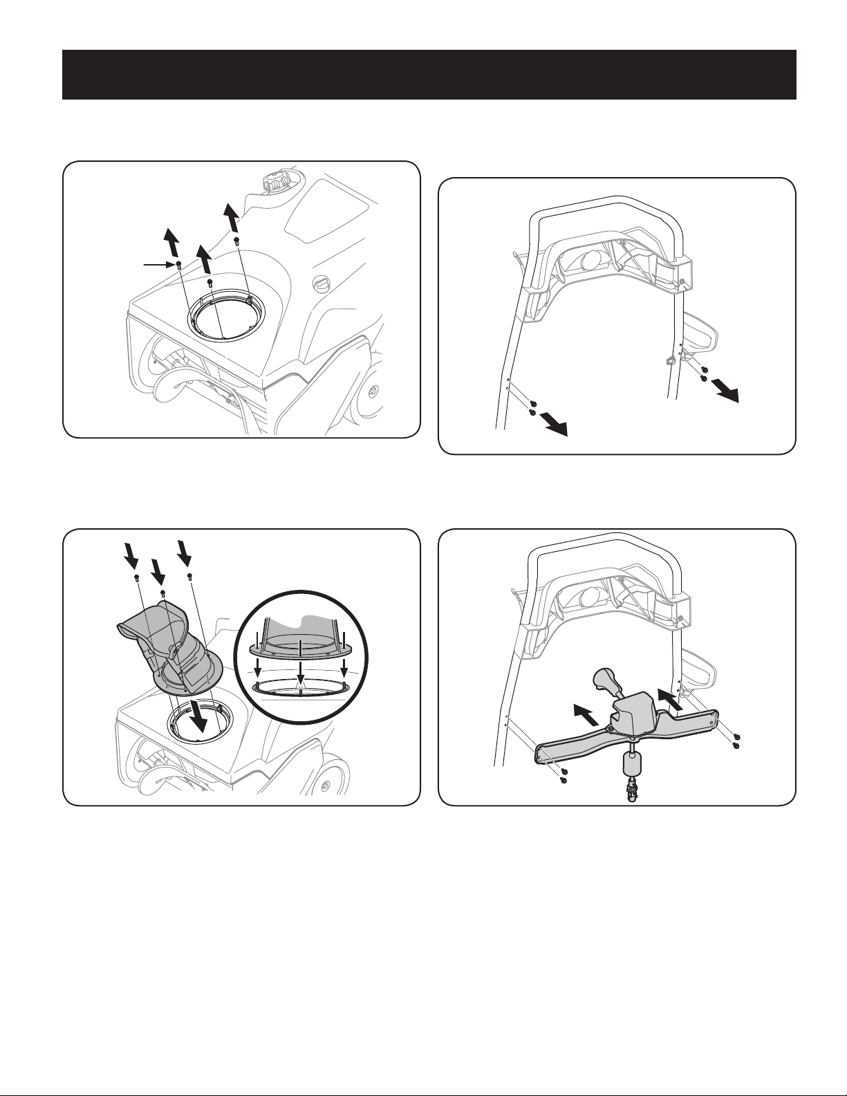
30
MONTAJE
Instalación del montaje del control de rotación del canal
1. Extraiga los cuatro tornillos de cabeza hexagonal de la parte posterior de la
manija (dos a cada lado). Vea la Figura 6.
Figura 6
2. Usando los cuatro tornillos de cabeza hexagonal, instale el montaje del
control de rotación del canal. Vea la Figura 7.
Figura 7
Instalación del canal
1. Extraiga los tornillos de cabeza hexagonal de la base del canal. Vea la Figura 4.
Tornillo
de cabeza
hexagonal
Figura 4
2. Alinee los orificios de la base del canal con los orificios del canal inferior y
sujételo con los tornillos de cabeza hexagonal que extrajo anteriormente.
Vea la Figura 5.
Figura 5
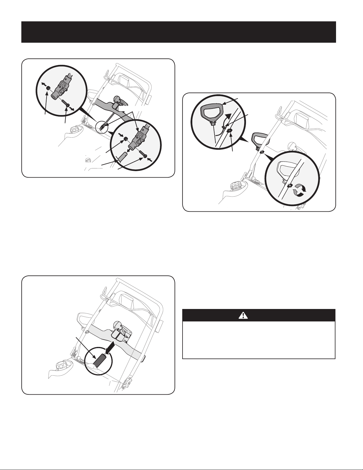
31
MONTAJE
3. Retire el tornillo y la tuerca hexagonal de la junta universal. Vea la Figura 8.
Tuerca de
seguridad
hexagonal
Tornillo
Junta universal
Tuerca de seguridad hexagonal
Varilla del canal
Tornillo
Figura 8
NOTA: Compruebe que el canal esté orientado hacia adelante cuando instale
la junta universal.
4. Coloque la junta universal en el extremo de la varilla del canal como se indica
en la Figura 8.
NOTA: Compruebe que los orificios de la junta universal se alineen con los
orificios de la varilla del canal. Es posible que tenga que activar el disparador
para poder alinear los orificios.
5. Sujete la junta universal con la tuerca hexagonal y el tornillo que extrajo
previamente. Vea la Figura 8.
6. Deslice el manguito de protección sobre la junta universal. Vea la Figura 9.
Manguito de protección
Figura 9
Instalación de la manija del arrancador de retroceso
1. Retire el perno de ojo y la perilla de la manija de la bolsa del manual.
2. Coloque el perno de ojo y la perilla de la manija en la manija superior como
se indica en la Figura 10. No ajuste completamente los herrajes hasta que se
le indique que lo haga.
Manija del arrancador de retroceso
Perno de ojo
Botón de mango
Figura 10
NOTA: La abertura del perno de ojo debe estar orientada hacia la parte
posterior de la máquina quitanieve.
3. Tire lentamente de la manija del arrancador de retroceso hacia arriba hacia
el perno de ojo.
4. Deslice la cuerda del arrancador de retroceso dentro del perno de ojo desde
la parte posterior de la máquina quitanieve. Vea la Figura 10.
5. Ajuste bien el perno de ojo y la perilla de la manija.
Configuración
Recomendaciones sobre el combustible
PRECAUCIÓN
El funcionamiento del motor con el combustible E15 o E85, una mezcla de aceite
con la gasolina, la gasolina sucia, o la gasolina de más de 30 días de edad que
no ha sido aditivo estabilizador de combustible puede resultar en daños al
carburador de su motor. Daños posteriores no estarían cubiertos por la garantía
del fabricante.
Utilice gasolina para automóviles (sin plomo o bajo contenido de plomo para
minimizar los depósitos en la cámara de combustión) con un mínimo de 87 octanos.
Se puede usar gasolina con hasta un 10% de etanol (E10) o un 15% de MTBE (éter
metílico terciario-butílico). Nunca use una mezcla de aceite y gasolina ni gasolina
sucia. Evite que se introduzca suciedad, polvo o agua en el tanque de combustible.
NO utilice gasolina E15 o E85.
• Cargue combustible en un área bien ventilada y con el motor apagado. No
fume ni permita llamas o chispas en el lugar donde se carga combustible o se
almacena la gasolina.
• No llene en exceso el depósito de combustible. Después de cargar
combustible, asegúrese de que el tapón del depósito esté bien cerrado y
asegurado.
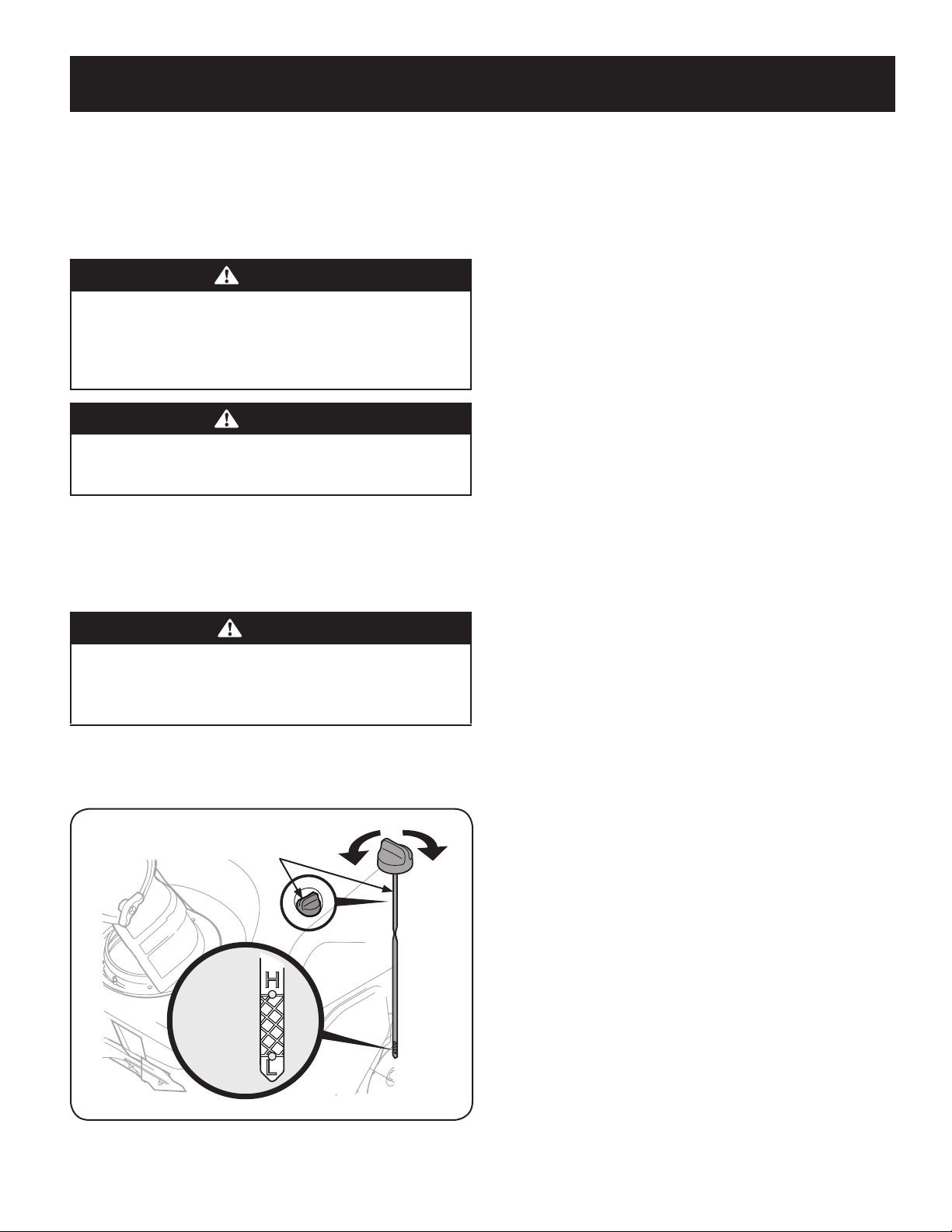
32
MONTAJE
• Tenga cuidado de no derramar combustible al realizar la recarga. El
combustible derramado o sus vapores se pueden incendiar. Si se derrama
combustible, asegúrese de que el área esté seca antes de arrancar el motor.
• Evite el contacto repetido o prolongado con la piel y la inhalación de los
vapores.
Carga de combustible
ADVERTENCIA
Tenga mucho cuidado al trabajar con gasolina. La gasolina es sumamente
inflamable y sus vapores pueden causar explosiones. Nunca agregue
combustible a la máquina en interiores ni mientras el motor está caliente
o en funcionamiento. Apague cigarrillos, cigarros, pipas y otras fuentes de
combustión.
ADVERTENCIA
Siempre mantenga las manos y los pies alejados de las piezas móviles
del equipo. No utilice fluidos comprimidos para arrancar. Los vapores son
inflamables.
Extraiga la tapa del combustible, controle el nivel y cargue más combustible de ser
necesario. Cargue el depósito hasta que el combustible llegue a 1⁄2 pulgada por
debajo de la base del cuello de llenado para dejar espacio para la expansión del
combustible. Tenga cuidado de no llenar en exceso.
Procedimiento para controlar y agregar aceite
PRECAUCIÓN
El motor se envía sin aceite en el motor. Debe llenar el motor con aceite
SAE 5W-30, se entrega con la unidad, antes de operar. Si se hace
funcionar el motor sin suficiente aceite puede causar daños graves al
motor y anular la garantía del producto.
1. Coloque la máquina quitanieve en una superficie firme y nivelada.
2. Retire el tapón de llenado/varilla de medición de aceite y limpie bien la
varilla. Vea la Figura 11.
Se debe cargar
entre las marcas
de nivel alto y
bajo.
Tapón de llenado de aceite/varilla
de medición del nivel de aceite
Figura 11
3. Introduzca el tapón / la varilla de medición de aceite dentro del cuello de
llenado de aceite pero no los atornille.
4. Saque el tapón / la varilla de medición de aceite. Poco a poco agregue el
aceite en el depósito hasta que el nivel de aceite se registra entre la alta (H)
y baja (L), Figura 11.
NOT
A: No lo llene en exceso. Si se carga demasiado aceite se puede generar
humo, problemas de arranque o suciedad en la bujía.
5. Vuelva a colocar el tapón / la varilla de medición de aceite bien ajustados
antes de poner en marcha el motor.
NOTA: NO permita que el nivel de aceite caiga por debajo de la marca “L” de
la varilla de medición. Si lo hace el equipo puede funcionar mal o dañarse.
NOTA: Para cambiar el aceite del motor, consulte la sección de
Mantenimiento de este manual.
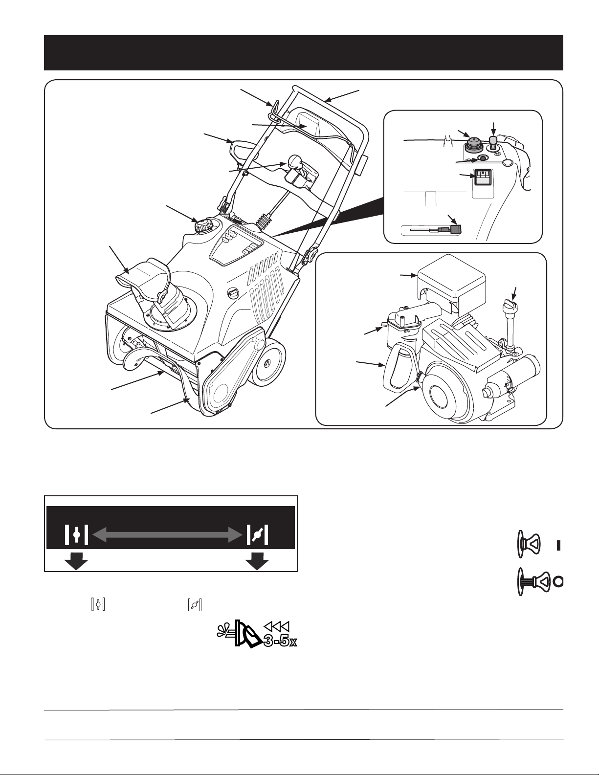
33
FUNCIONAMIENTO
Ahora que ya ha ajustado su máquina quitanieve para el funcionamiento, es
importante familiarizarse con sus controles y características. Consulte la Figura 1.
Control del cebador
RUN
CHOKE
RUN
CHOKE
CHOKE BELOW
Al activar el control del cebador se cierra la placa estranguladora del carburador
y se ayuda a arrancar el motor. La palanca del estrangulador se desliza entre las
posiciones RUN
(funcionamiento) y CHOKE (estrangulador).
Cebador
Presione el cebador, asegurándose de cubrir el orificio
de ventilación cuando lo haga, de esa manera se
envía combustible directamente al carburador del motor para ayudar al encendido
cuando el clima es frío.
Manija del arrancador de retroceso
La manija del arrancador de retroceso se utiliza para encender el motor.
Tapón de combustible
Saque el tapón del combustible para agregar combustible.
Llave
La llave es un dispositivo de seguridad. Debe estar completamente
insertada para que el motor arranque. Extraiga la llave cuando no
use la máquina quitanieve.
NOTA: No gire la llave para intentar arrancar el motor.
Al hacerlo podría romperla.
Barrena
Cuando está engranada, la rotación de la barrena dirige la nieve dentro de la caja de
la barrena y la arroja hacia afuera por el canal de descarga. Las paletas de caucho de
la barrena también ayudan a impulsar la máquina quitanieve al ponerse en contacto
con el pavimento.
Cumple con los estándares de seguridad de ANSI
Las máquinas quitanieve Craftsman cumplen con los estándares de seguridad del Instituto Estadounidense de Estándares Nacionales (ANSI).
Manija de Superior
Montaje del canal
Placa de raspado
Barrena
Manija del arrancador de retroceso
Tapa de combustible
Control de la barrena
Palanca del cebador
Cebador
Llave
Salida del arrancador
eléctrico
Botón del
arrancador eléctrico
Varilla de llenado/
nivel de aceite
Silenciador
Manija del
arrancador
de retroceso
Palanca del
cebador
Drenaje del aceite
Faro delantero
Control de rotación del canal
Figura 1
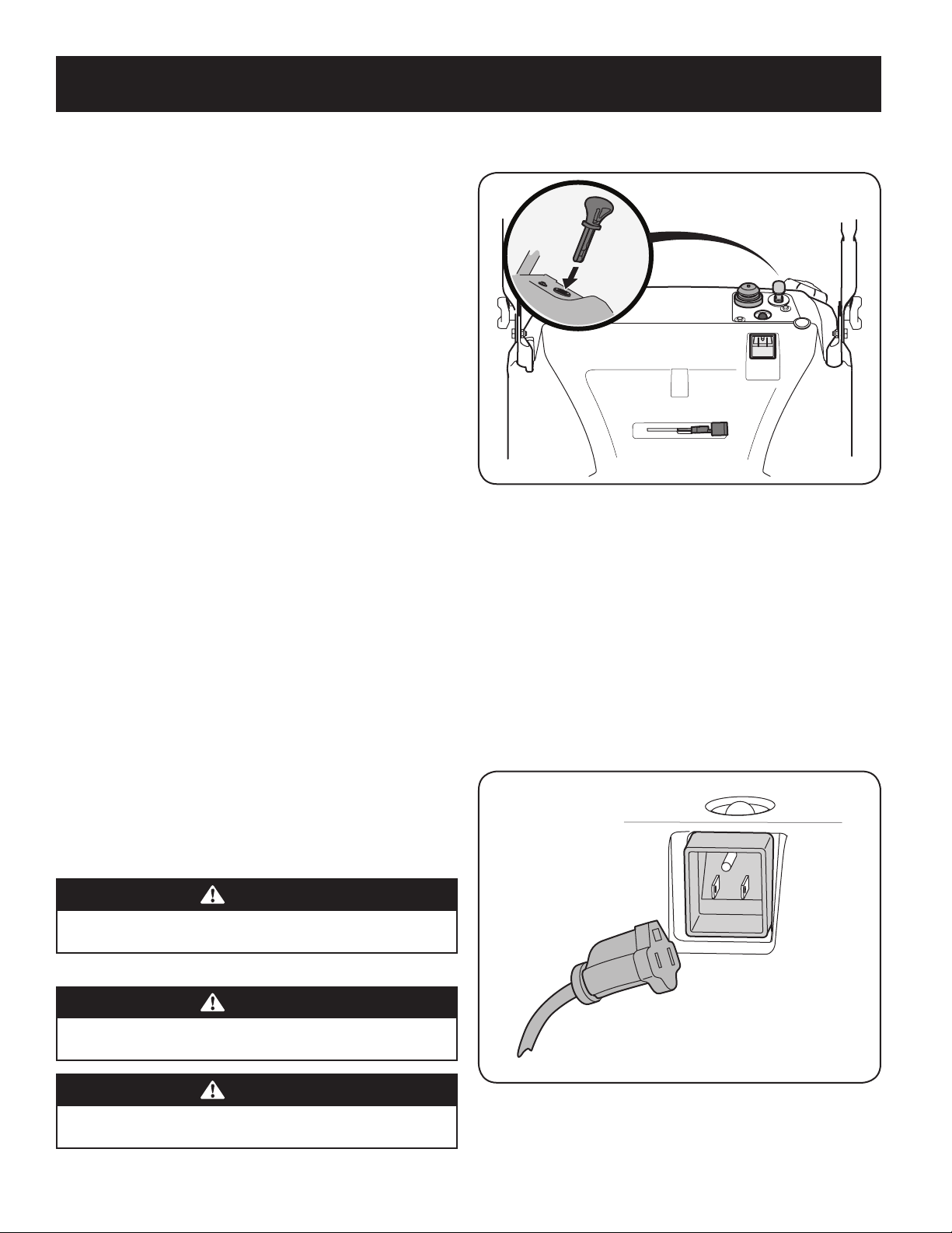
34
FUNCIONAMIENTO
Control de la barrena
La manija de control de la barrena está ubicada en la barra superior y se usa para engranar
y desengranar la transmisión de la barrena. Apriete la manija de control contra la barra de
control superior para engranar la barrena, aflójela para desengranarla.
Silenciador
El escape del motor sale del motor a través del silenciador.
Control de rotación del canal
El control de rotación del canal está ubicado en el centro del panel de control y
controla la dirección en que se arroja la nieve. Oprima el botón y rote el control de
rotación del canal hacia la derecha para girar el canal hacia la derecha y rótelo hacia
la izquierda para que el canal gire a la izquierda.
Montaje del canal
La inclinación del canal de descarga controla el ángulo con el que se arroja la nieve. Afloje la
perilla de aletas del costado del canal de descarga antes de girar el canal de descarga hacia
arriba o hacia abajo. Vuelva a ajustar la perilla después de alcanzar la posición deseada.
Placa de raspado
La placa de raspado hace contacto con el pavimento a medida que se impulsa la
máquina quitanieve, permitiendo que se descargue la nieve que está cerca de la
superficie del pavimento.
Varilla de llenado/nivel de aceite
Es posible controlar el nivel de aceite del motor, así como también agregar aceite, a
través del llenado de aceite.
Drenaje del aceite
El aceite del motor se puede drenar a través del tubo de drenaje.
Faro delantero
El faro delantero está ubicado en la parte central superior del panel de control y se
enciende cuando la máquina quitanieve está en marcha.
Salida del arrancador eléctrico
Es necesario usar un prolongador para exteriores de tres patas y una fuente de
alimentación / tomacorriente de pared de 120V.
Botón del arrancador eléctrico
Si oprime el botón del arrancador eléctrico se engrana el arrancador eléctrico del motor
cuando se lo enchufa a una fuente de energía de 120V.
Antes de arrancar el motor
ADVERTENCIA
Lea, comprenda y siga todas las instrucciones y advertencias que aparecen
en la máquina y en este manual antes de hacerla funcionar.
Encendido del motor
ADVERTENCIA
Siempre mantenga las manos y los pies alejados de las partes móviles. No
utilice fluidos comprimidos para arrancar. Los vapores son inflamables.
ADVERTENCIA
Para evitar el envenenamiento por monóxido de carbono, asegúrese de
que el motor esté al aire libre en un área bien ventilada.
1. Verifique que el control de la barrena se encuentre en posición
desenganchada (suelta).
2. Inserte la llave de encendido en la ranura. Asegúrese de que entre a presión en
su lugar. No intente girar la llave. Vea la Figura 2.
Figura 2
NOTA: El motor no puede arrancar si la llave no está completamente
insertada en el interruptor de encendido.
Botón del arrancador
Determine si el cableado de su hogar es un sistema de tres cables conectado a tierra.
Consulte con un electricista matriculado si no
está seguro.
Si cuenta con un receptáculo para tres patas conectado a tierra, realice los siguientes
pasos:
1. Conecte el prolongador a la salida situada en la superficie del motor. Conecte
el otro extremo del prolongador a un tomacorriente de CA, 120 voltios con
conexión a tierra, para tres patas, en un área bien ventilada. Vea la Figura 3.
Figura 3
35
FUNCIONAMIENTO
.
2. Empuje la palanca del estrangulador a la posición CHOKE (estrangulador)
3. Si el motor ya está caliente, ubique el regulador en la posición RUN
funcionamiento) en lugar de CHOKE (estrangulador) .
4. Presione tres (3) a cinco (5) veces el botón de cebado, asegurándose de
cubrir el orificio de ventilación al presionar.
5. Si el motor está caliente, presione el botón del cebador una sola vez.
6. Presione el botón del arrancador para arrancar el motor.
7. Una vez encendido el motor, suelte el botón del arrancador.
8. Deje que el motor se caliente varios minutos, ajustando el estrangulador
hacia la posición RUN (funcionamiento) . Espere hasta que el motor
funcione suavemente antes de cada ajuste de la obturación.
9. Cuando desconecte el prolongador, desenchufe siempre el extremo
que está en el tomacorrientes de tres patas de la pared antes de desenchufar
el extremo opuesto que está en la máquina quitanieve.
Arrancador de retroceso
.
1. Empuje la palanca del estrangulador a la posición CHOKE (estrangulador)
2. Si el motor ya está caliente, ubique el regulador en la posición RUN
(funcionamiento) en lugar de CHOKE (estrangulador) .
3. Presione tres (3) a cinco (5) veces el botón de cebado, asegurándose de
cubrir el orificio de ventilación al presionar.
4. Si el motor está caliente, presione el botón del cebador una sola vez.
Detención del motor
1. Haga funcionar el motor durante unos minutos sin carga antes de parar para
ayudar a secar la humedad en el motor.
2. Para detener el motor saque la llave y guárdela en un lugar seguro.
3. Limpie toda la nieve y la humedad del área de los controles del motor.
ADVERTENCIA
El silenciador, el motor y las áreas circundantes se recalientan y pueden
causar quemaduras. Sea precavido y no los toque cuando están calientes.
Enganche de la barrena
Para engranar la barrena apriete la manija de control contra la barra de control
superior. Suelte el control para detener la barrena.
Enganche de la transmisión
Levante ligeramente el asa superior para permitir que las paletas de goma en el
sinfín de ponerse en contacto con el pavimento e impulsar el quitanieves hacia
delante. Empujando hacia abajo sobre la manija levantar la barrena de la tierra y
detener el movimiento hacia adelante.
NOTA: Si la presión ascendente sobre la manija es excesiva tendrá como
resultado un desgaste prematuro de las paletas de caucho de la barrena y
esto no estará cubierto por la garantía.
Despeje de un canal de descarga obstruido
El contacto de las manos con el impulsor rotatorio que está dentro del canal de
descarga es la causa más común de lesiones asociadas con las máquinas quitanieve.
Nunca use las manos para limpiar el canal de descarga.
Para despejar el canal:
1. ¡APAGUE EL MOTOR!
2. Espere 10 segundos para estar seguro de que las cuchillas del motor han
dejado de rotar.
3. Utilice siempre una herramienta de limpieza o varilla, no use las manos.
Funcionar la máquina quitanieve
• Una vez que la unidad de la barrena se engrana, rodar el quitanieves en la
capa de nieve para ser retirado.
• Ajuste el canal inclinado de manera que la nieve no se lanza sobre otro nieve
que ha de ser eliminado.
• Evitar posibles daños a la propiedad o lesiones personales de rechazo objeto
mediante la planificación de su patrón arrojando nieve para evitar la
descarga hacia las ventanas, paredes, coches, etc.
• No sobrecargue la capacidad de la máquina intentando quitar la nieve
demasiado rápido de una tasa.
• Nunca opere esta máquina sin buena visibilidad o luz.
• Siempre esté seguro de su equilibrio y sujetando firmemente las manijas.
• Camine, nunca haga funcionar cuando se opera la máquina quitanieves.
• Mire hacia abajo y hacia atrás y tenga cuidado al dar march
a atrás.
5. Tome la manija del arrancador de retroceso y tire de la cuerda hacia afuera
lentamente. En el punto que se hace levemente más difícil tirar de la
cuerda, permita que la misma retroceda lentamente.
6. Tire de la manija del arrancador con un movimiento firme y rápido. No
suelte La manija ni deje que retroceda a su posición original. Mantenga la
manija del arrancador firmemente sujeta y deje que la cuerda retroceda
lentamente.
7. Deje que el motor se caliente varios minutos, ajustando el estrangulador
h
acia la posición RUN (funcionamiento) . Espere hasta que el motor
funcione suavemente antes de cada ajuste de la obturación.
WARNING
Al tirar de la cuerda de arranque, la cuerda de forma inesperada puede
tirar de nuevo hacia el motor y causar lesiones graves. Para evitar este
riesgo, siga cuidadosamente las instrucciones de abajo.
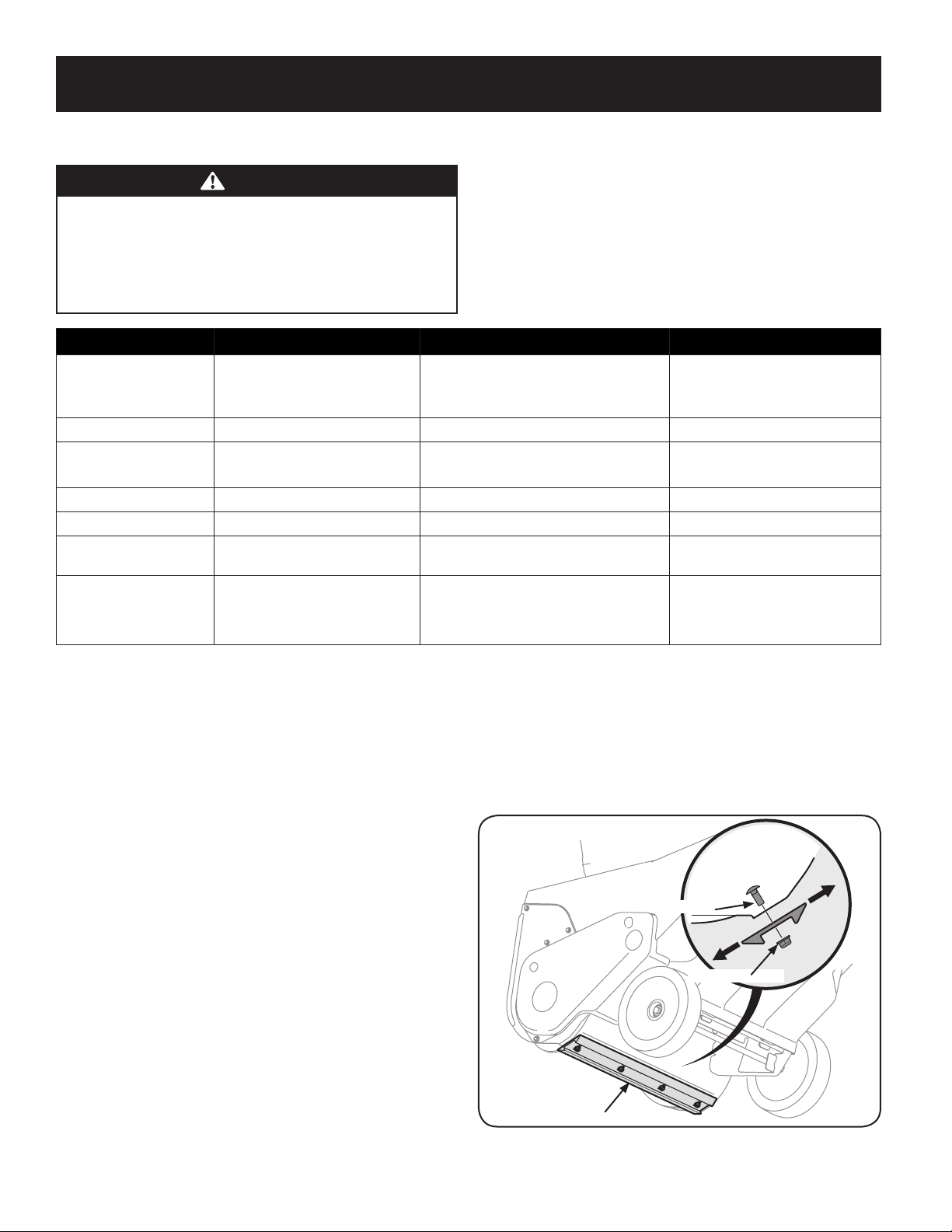
36
SERVICIO Y MANTENIMIENTO
ADVERTENCIA
Antes de realizar cualquier tipo de mantenimiento o servicio, desenganche
todos los controles y detenga el motor. Espere a que se detengan
completamente todas las piezas móviles. Desconecte el cable de la bujía
y póngalo haciendo masa contra el motor para evitar que se encienda
accidentalmente. Utilice siempre anteojos de seguridad durante el
funcionamiento o mientras ajusta o repara este equipo.
PROGRAMA DE MANTENIMIENTO
Siga el programa de mantenimiento a continuación. Esta tabla se describen las
pautas de servicio solamente. Utilice la columna Registro de servicio para
realizar un seguimiento de las tareas de mantenimiento realizadas. Para
programar el servicio de Sears Parts & Repair, llame al 1-888-331-4569.
Intervalo Artículo Servicio Registro de servicio
Cada uso
1. Nivel de aceite del motor.
2. Máquina quitanieve y área de
escape.
1. Verificar.
2. Limpiar.
1ras 5 horas
1. Aceite del motor. 1. Cambio.
Cada 5 horas
2. Aceite del motor.
3. Área del escape.
1. Verificar.
2. Clean.
25 horas
1. Bujía de encendido. 2. Verificar. (Consulte el manual del motor)
Cada temporada/50 horas
1. Aceite del motor. 1. Cambio.
Cada temporada/100 horas
1. Puntos de pivote. 1. Limpiar, reemplazar, regular. (Consulte el
manual del motor)
Cada temporada/antes de
almacenar
1. Puntos de pivote.
2. Manija de control.
3. Resorte de extensión.
1. Lubricar.
2. Lubricar.
3. Lubricar.
Mantenimiento
Motor
Consulte el Manual del operador del motor para todos los procedimientos de mantenimiento
del motor. Comprobación, añadir y cambiar el aceite también se encuentran en este manual.
Lubricación
Lubrique los puntos de giro de la manija de control y del resorte de extensión del
extremo del cable de control con un aceite liviano una vez por temporada y antes de
almacenar la máquina quitanieve al final de la temporada.
Ajustes
Placa de raspado
Para verificar el ajuste de la placa de raspado, ubique la unidad sobre una superficie
nivelada. Las ruedas, la placa de raspado y las paletas de la barrena deben tocar
la superficie nivelada. Tenga en cuenta que si la placa de raspado está demasiado
alta la nieve puede volar debajo de la caja de la barrena. Si la placa de raspado se
desgasta excesivamente, o la unidad no se autopropulsa, es posible que la placa de
raspado esté demasiado baja y deba ser ajustada.
NOTA: En las unidades nuevas o en las que tienen una placa de raspado nueva las
paletas de la barrena pueden estar un poco separadas del suelo.
Para ajustar la placa de raspado proceda de la siguiente manera:
1. Ponga en marcha la máquina quitanieve hasta que el tanque de combustible
esté vacío.
2. Jale de la cuerda de arranque hasta sentir resistencia. Luego incline la
máquina quitanieve hacia atrás hasta que quede apoyada sobre las manijas.
Para asegurar que la máquina quitanieve no se incline hacia adelante, puede
ser necesario sujetar la manija al piso con un bloque u otro objeto.
3. Afloje las cuatro tuercas de seguridad con brida y los pernos de carro que
sujetan la placa de raspado a la caja. Vea la Figura 1. Mueva la placa de
raspado hacia la posición deseada y vuelva a apretar las tuercas y los tornillos
hasta que queden bien ajustados.
Vista lateral
Tuerca de seguridad
Tornillo
Placa de raspado reversible
Figura 1
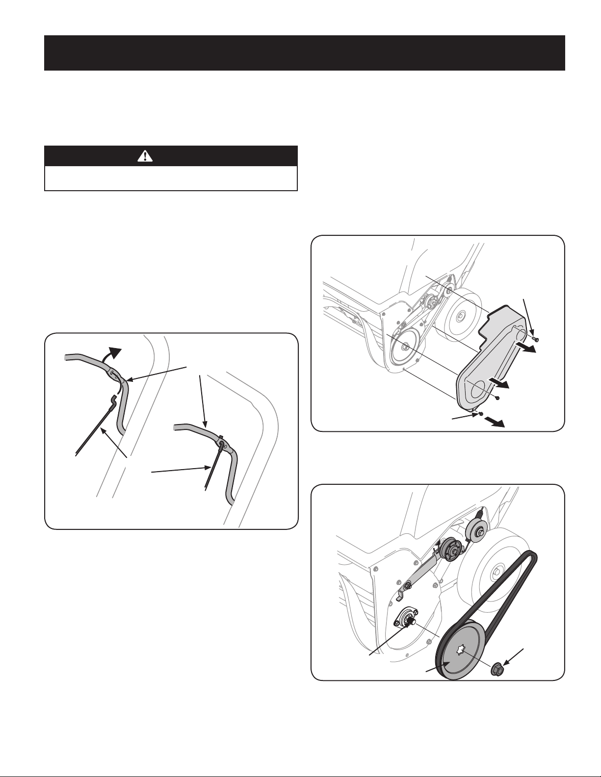
37
SERVICIO Y MANTENIMIENTO
4. Incline la máquina quitanieve hacia atrás a la posición de funcionamiento y
tire del tirador del estárter un par de veces para ver si es difícil de lograr.
5. Si es difícil jalar del arranque, extraiga la bujía y jale de la manija varias veces
para estar seguro de que se extraiga cualquier cantidad de aceite que haya
quedado atrapada en la culata del motor.
PRECAUCIÓN
Puede salir aceite del orificio de la bujía cuando la misma se extrae y se jala de la
manija de arranque.
6. Inspeccione la bujía. Si está húmeda, limpie cualquier resto de aceite antes
de volver a instalar.
Cable de control
Es posible que necesite realizar ajustes periódicos debido al estiramiento del cable
de control y de la correa de transmisión ocasionado por el desgaste. Si la barrena
parece titubear mientras gira, haga lo siguiente:
1. El agujero superior de la barra de control prevé el ajuste de la tensión del
cable. Para realizar el ajuste, desconecte el extremo del cable de control del
agujero inferior de la manija de control e insértelo en el agujero superior.
Inserte el cable desde el exterior como se indica en la Figura 2.
Cable de
control
Manija de
control
Figura 2
2. Pruebe la máquina quitanieve para ver si se logra una diferencia apreciable.
Si luego de realizado el ajuste del cable de control la barrena sigue
titubeando al girar, consulte la sección Reemplazo de la correa para obtener
las instrucciones para el reemplazo de la correa.
Montaje del canal
Consulte la sección Montaje para ver las instrucciones del ajuste del montaje del
canal.
Reemplazo de la correa de transmisión de la barrena
1. Ponga en marcha la máquina quitanieve hasta que el tanque de combustible
esté vacío.
2. Jale de la manija del arrancador de retroceso hasta sentir resistencia. Luego
incline la máquina quitanieve hacia atrás hasta que quede apoyada sobre las
manijas.
3. Deslice una tabla hacia arriba a través de la barrena y a través del canal para
sujetar la barrena en su lugar.
4. Para sacar la cubierta de la correa saque los dos tornillos de cabeza
hexagonal y un tornillo de seguridad hexagonal que la sujetan al bastidor.
Vea la Figura 3.
Tornillo de cabeza hexagonal
Tornillo de seguridad
hexagonal
Figura 3
5. Extraiga la tuerca de brida que sujeta la polea de la barrena al eje de la
barrena. Vea la Figura 4.
Tuerca con
reborde
Polea de la barrena
Eje de la barrena
Figura 4
6. Extraiga la polea de la barrena y la correa.
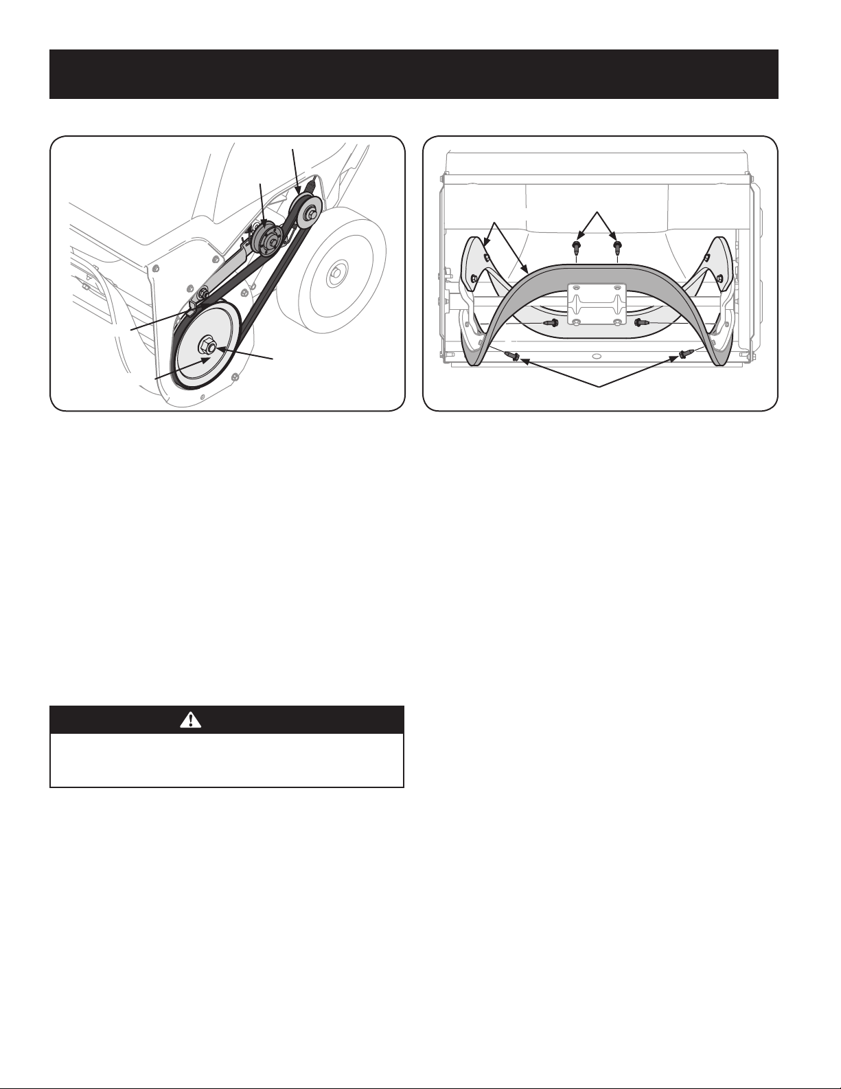
38
SERVICIO Y MANTENIMIENTO
Para volver a colocar la correa siga estas instrucciones y consulte la Figura 5:
Polea de la barrena
Guardacorrea
Polea loca
Tuerca con reborde
Polea de transmisión
Figura 5
1. Pase la correa alrededor de la polea de transmisión y por debajo de la polea
loca.
2. Pase el extremo de la correa alrededor de la polea de la barrena y deslice
la polea hacia atrás sobre el eje de la barrena. Puede ser necesario empujar
hacia abajo la polea loca para hacer que la polea de la barrena pase por
debajo del guardacorrea.
3. Vuelva a colocar la tuerca de brida y ajústela bien.
4. Apriete la palanca de control de la barrena contra la manija superior y volver
a instalar la cubierta de la correa que sacó anteriormente.
5. Quite la tabla de la barrena y el canal.
Reemplazo de las paletas de la barrena
Las paletas de caucho de la barrena de la máquina quitanieve están sujetas a
desgaste y podrían ser reemplazadas si aparecieran indicios de desgaste excesivo.
PRECAUCIÓN
NO permita que las paletas de caucho de la barrena se desgasten hasta el
punto en que partes de la barrena metálica misma toquen el pavimento. Si
esto sucede la máquina quitanieve puede dañarse seriamente.
Para cambiar las paletas de caucho, proceda como sigue y consulte la Figura 6:
Tornillo de cabeza hexagonal
Tornillo de cabeza hexagonal
Paleta de la barrena
Figura 6
1. Ponga en marcha la máquina quitanieve hasta que el tanque de combustible
esté vacío.
2. Jale de la manija del arrancador de retroceso hasta sentir resistencia. Luego incline
la máquina quitanieve hacia atrás hasta que quede apoyada sobre las manijas.
3. Saque las paletas de caucho ya existentes para lo cual desenrosque los
tornillos de cabeza hexagonal que las unen a la barrena. Vea la Figura 19.
NOTA: Las paletas de la barrena deben reemplazarse una a la vez de manera
que se pueda usar la paleta de la barrena aún conectada como ejemplo para
el posicionamiento y la reinstalación de la barrena nueva.
4. Ajuste las nuevas paletas de caucho a la barrena usando los elementos de
ferretería que sacó anteriormente.
Un kit de barrena de repuesto completo que incluya las paletas de caucho y los
tornillos para arandelas hexagonales comuníquese con Sears al teléfono 1-888-331-
4569. Pida la pieza 753-06469.
Invertir o cambiar la placa de raspado
La placa de raspado está adosada al fondo de la caja de la barrena y sujeta a
desgaste. Se la debe controlar periódicamente. La placa de raspado tiene dos bordes
de desgaste y se la puede invertir.
1. Ponga en marcha la máquina quitanieve hasta que el tanque de combustible
esté vacío.
2. Jale de la manija del arrancador de retroceso hasta sentir resistencia. Luego incline
la máquina quitanieve hacia atrás hasta que quede apoyada sobre las manijas.
3. Quite los cuatro pernos de carro y las tuercas de seguridad con brida que la
sujetan a la caja de la máquina quitanieve. Consulte la figura 14 en la página 46.
4. Invierta la placa de raspado existente o instale una nueva, comprobando que
la placa de raspado nueva y las cabezas de los pernos de carro queden en el
interior de la caja.
5. Coloque la placa de raspado como se indica en la página 46.
6. Una vez colocada, ajuste bien.
Para obtener una placa de raspado nueva, comuníquese con Sears al teléfono 1-888-
331-4569. Pida la pieza n.º 731-07667.
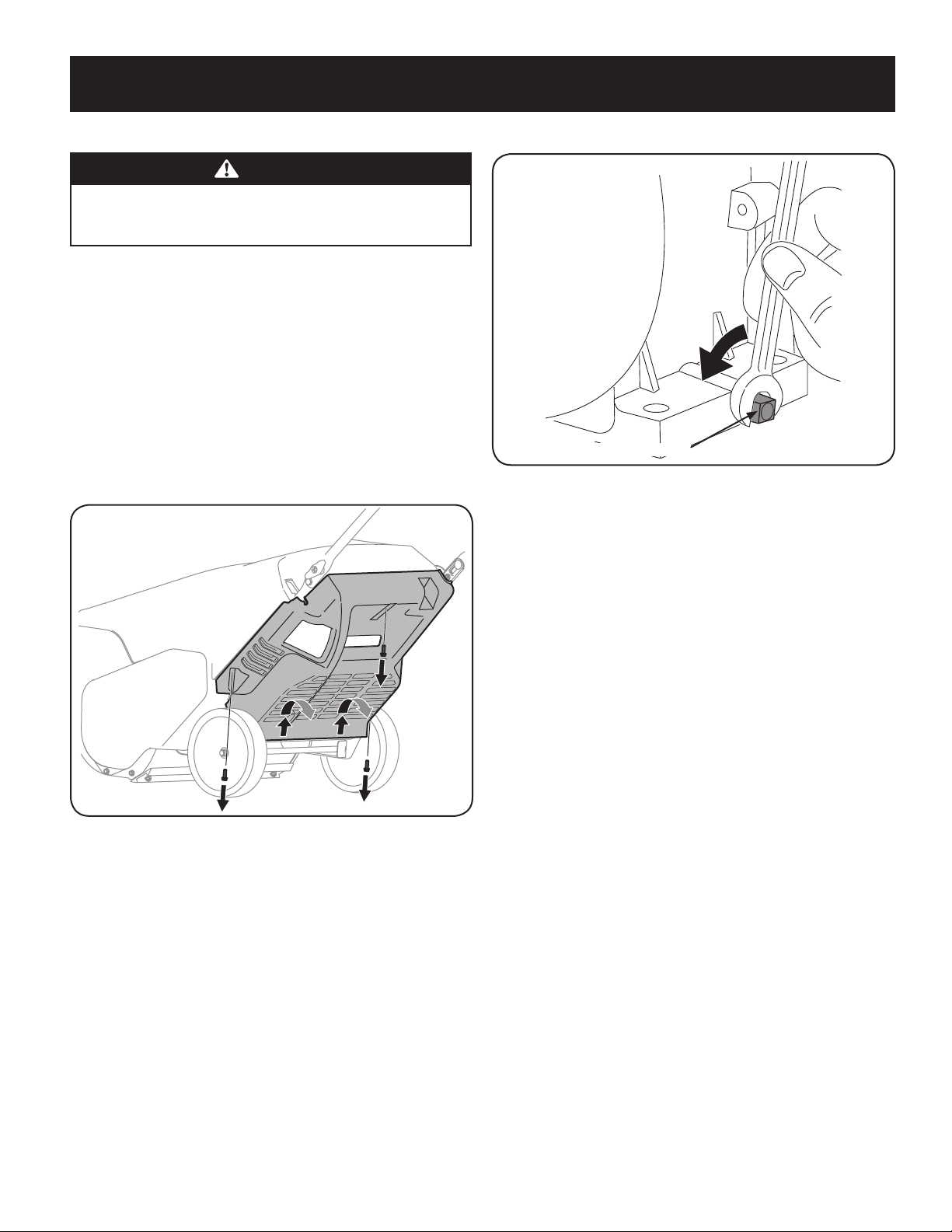
39
SERVICIO Y MANTENIMIENTO
Cambio del aceite del motor
ADVERTENCIA
Apague el motor y retire la llave de encendido antes de realizar cualquier
trabajo de mantenimiento. Para evitar una puesta en marcha accidental,
desconecte la funda de la bujía.
Controle el nivel de aceite antes de cada uso y cada 5 horas de funcionamiento cuando
el motor está tibio. Consulte Procedimiento para controlar y agregar aceite en la
sección Armado.
Cambie el aceite después de las 5 primeras horas de operación y cada 50 horas de
operación a partir de ese momento. El motor debe estar tibio aún pero NO caliente
por su uso reciente.
1. Drene el combustible del tanque haciendo funcionar el motor hasta que el
tanque de combustible está vacío. Asegúrese de que el tapón de llenado de
combustible es seguro.
2. Retire los tres tornillos que sujetan el panel inferior. Quite el panel inferior
levantando en el panel para liberar las pestañas en la parte inferior del panel
de las ranuras de la ficha y luego retirarse. Vea la Figura 7.
Figura 7
NOTA: La parte inferior del panel tiene etiquetas que ayudan a mantenerlo
en su lugar.
NOTA: Un kit de extensión del drenaje de aceite se encuentra disponible por
separado. Visite una de servico Sears Center o llamar 1-888-331-4569 y pedir
el kit #753-06684.
3. Colocar un recipiente de recolección de aceite adecuado debajo del tapón de
drenaje.
4. Retire el tapón de vaciado, la Figura 8.
Tapón de drenaje de aceite
Figura 8
5. Incline la máquina quitanieves de nuevo a fuga de aceite en el recipiente. El
aceite usado deberá ser depositado en un centro de recolección adecuado.
6. Vuelva a colocar el tapón de vaciado y apriételo firmemente.
7. Rellene con el aceite recomendado y compruebe el nivel de aceite, consulte
Comprobación y adición de aceite en la Sección de la Asamblea.
8. Vuelva a colocar la tapa de relleno / varilla indicadora de nivel.
9. Vuelva a instalar el panel inferior mediante la colocación de las etiquetas de
las ranuras de la ficha, levantando el panel en su lugar y asegúrelo con los
tres tornillos que quitó en el paso 2.Bujía de encendido
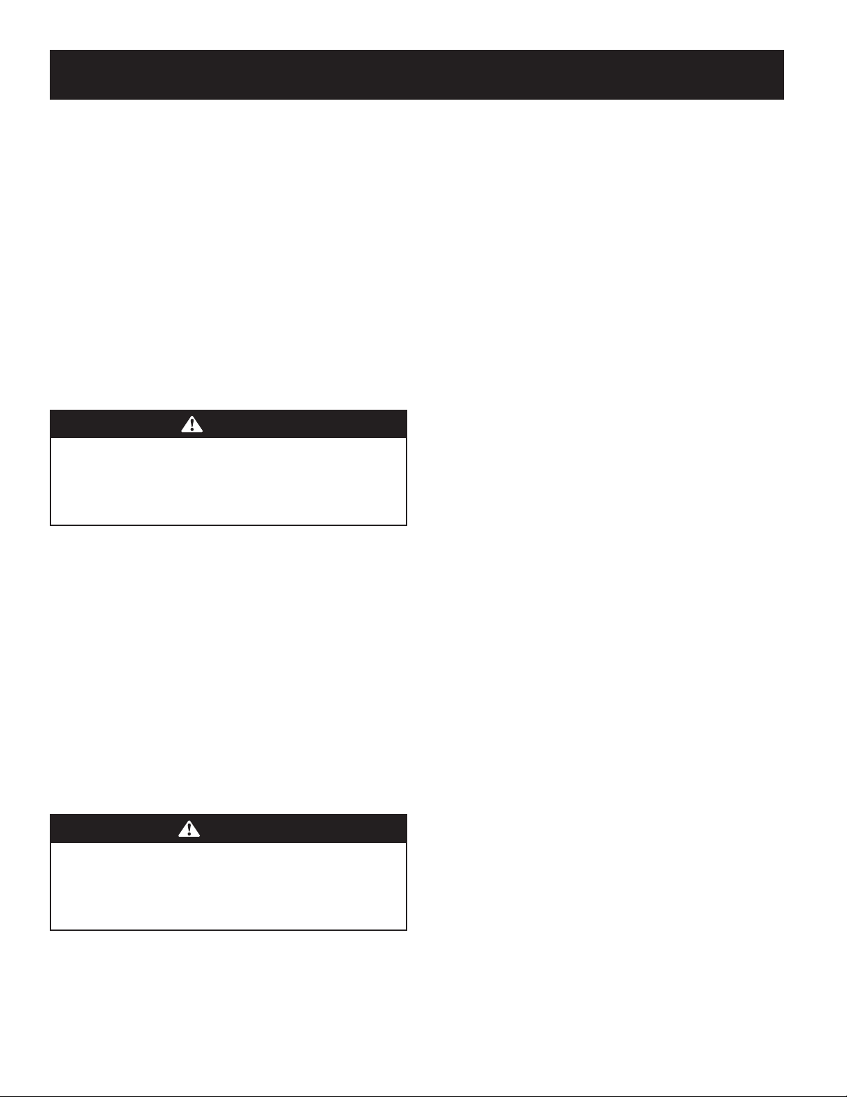
40
SERVICIO Y MANTENIMIENTO
Almacenamiento fuera de temporada
Preparación del motor
Los motores que se almacenan durante más de 30 días deben ser drenados de
combustible para evitar que se deterioren y se forme goma en el sistema de
combustible o en las piezas principales del carburador. Si la gasolina en su motor
se deteriora durante el almacenamiento, puede resultar necesario reparar o
reemplazar el carburador y otros componentes del sistema de combustible.
1. Elimine todo el combustible del tanque haciendo funcionar el motor hasta
que se detenga.
2. Cambie el aceite del motor.
3. Extraiga la bujía de encendido y vierta en el cilindro aproximadamente 1
onza (30 ml) de aceite para motor limpio. Tire varias veces del arrancador de
retroceso para distribuir el aceite y reinstale la bujía.
4. Limpie el exterior del motor eliminando la suciedad y los residuos de las
siguientes zonas:
PRECAUCIÓN
No rocíe el motor con agua para limpiarlo porque el agua podría
contaminar el combustible. Si se utiliza una manguera de jardín o equipo
de lavado a presión también puede entrar agua dentro de la abertura
del silenciador. El agua que pasa por el silenciador puede ingresar en el
cilindro, causando daños.
• Aletas de refrigeración
• Filtro de admisión de aire o Áreas de protección del volante/
arrancador de retroceso
• Conexión de la bujía
• Palancas
• Área de enlace
• Protecciones
• Carburador
• Culata del motor
5. Almacene el motor en un sector limpio, seco y bien ventilado, lejos de
cualquier artefacto que funcione con una llama o luz piloto como hornos,
calentadores de agua o secadores de ropa. Evite cualquier sector con un
motor eléctrico que produzca chispas o donde se utilicen herramientas
eléctricas.
ADVERTENCIA
Nunca almacene la máquina quitanieve con combustible en el tanque en
un espacio cerrado o en áreas con poca ventilación, donde los gases del
combustible puedan alcanzar el fuego, chispas o una luz piloto como la que
tienen algunos hornos, calentadores de agua, secadores de ropa o algún
otro dispositivo a gas.
6. Si es posible, evite sectores de almacenamiento con mucha humedad.
7. Mantenga el motor nivelado cuando lo almacene. La inclinación del motor
puede resultar en fugas de combustible o aceite.
Preparación de la máquina quitanieve
Si no se va a usar la máquina quitanieve durante 30 días o más, siga las siguientes
instrucciones incluidas a continuación
1. Almacene el equipo en un área despejada y seca.
2. Limpie la máquina quitanieve con un trapo y quite la suciedad o los residuos.
3. Si almacena la máquina quitanieve en un lugar mal ventilado, cubra las
piezas metálicas de la máquina con una capa delgada de aceite o silicona
como antioxidante.

41
SOLUCIÓN DE PROBLEMAS
ADVERTENCIA
Antes de realizar cualquier tipo de mantenimiento o servicio, desenganche todos los controles y detenga
el motor. Espere a que se detengan completamente todas las piezas móviles. Desconecte el cable de la
bujía y póngalo haciendo masa contra el motor para evitar que se encienda accidentalmente. Utilice
siempre anteojos de seguridad durante el funcionamiento o mientras ajusta o repara este equipo.
En esta sección se analizan problemas menores de servicio. Para ubicar el Centro de Servicio Sears más cercano o para programar un servicio,
simplemente comuníquese con Sears al teléfono 1-888-331-4569.
Problema Causa Solución
El motor no arranca 1. El tanque de combustible está vacío o el
combustible se ha echado a perder.
2. La línea del combustible está bloqueada.
3. No se introdujo completamente la llave.
4. Se ha desconectado el cable de la bujía.
5. La bujía no funciona correctamente.
6. El motor no está cebado.
7. El motor está ahogado ya que ha sido cebado
demasiado.
1. Llene el depósito con gasolina limpia y nueva.
2. Comuníquese con el centro de servicio Sears.
3. Introduzca completamente la llave.
4. Conecte el cable a la bujía.
5. Limpie la bujía, ajuste la distancia disruptiva o
cambie la bujía.
6. Oprima el botón del cebador del motor entre
tres y cinco veces.
7. Aguarde al menos diez minutos antes de
encender el motor.
El motor funciona de
manera errática/RPM
desiguales (oscilación o
sobretensión)
1. El motor está funcionando en la posición “choke”
(cebador).
2. La línea del combustible está tapada o el
combustible es viejo.
3. Hay agua o suciedad en el sistema de
combustible.
4. Es necesario regular el carburador.
5. Exceso de regulación del motor.
1. Mueva la palanca del cebador a la posición RUN
(marcha).
2. Comuníquese con el centro de servicio Sears.
3. Haga funcionar el motor hasta que el depósito
de combustible esté vacío. Vuelva a llenar el
depósito con combustible nuevo.
4. Comuníquese con el centro de servicio Sears.
5. Comuníquese con el centro de servicio Sears.
El motor recalienta
1. Es necesario regular el carburador. 1. Comuníquese con el centro de servicio Sears.
Pérdida de potencia 1. El cable de la bujía está flojo.
2. La ventilación de la tapa del combustible está
obstruida.
1. Conecte firmemente el cable de la bujía.
2. Destape la ventilación.

42
SOLUCIÓN DE PROBLEMAS
Problema Causa Solución
Vibración excesiva 1. Hay piezas que están flojas o la barrena está
dañada.
1. Detenga el motor de inmediato y retire la llave.
Controle si la máquina está dañada. Ajuste todos
los pernos y las tuercas. Realice las reparaciones
necesarias. Si el problema persiste, lleve la
máquina quitanieve al centro de servicio Sears.
La máquina quitanieve no
arranca
1. El cable del control de la barrena necesita un
ajuste.
2. La correa de transmisión de la barrena está floja
o dañada.
1. Ajuste el cable de control de la barrena tal y
como se muestra en la sección de Servicio y
Mantenimiento.
2. Reemplace la correa de transmisión de la
barrena.
La barrena continúa
rotando
1. El cable del control de la barrena necesita un
ajuste.
1. Ajuste el cable de control de la barrena tal y
como se muestra en la sección de Servicio y
Mantenimiento.
La unidad no descarga la
nieve
1. El conjunto del canal está tapado.
2. Hay un objeto extraño en la barrena.
3. El cable del control de la barrena necesita un
ajuste.
4. La correa de la barrena está floja o dañada.
1. Detenga el motor y desconecte el cable de la
bujía. Limpie el canal y el interior de la caja de
la barrena con la herramienta de limpieza o una
varilla.
2. Detenga el motor de inmediato y desconecte el
cable de la bujía. Retire el objeto de la barrena.
3. Ajuste el cable del control de la barrena.
4. Reemplace la correa de la barrena.

ACUERDO DE PROTECCIÓN PARA REPARACIONES
43
Felicitaciones por haber realizado una adquisición inteligente. El producto Craftsman® que ha adquirido está diseñado y
fabricado para brindar muchos años de funcionamiento confiable. Pero como todos los productos a veces puede requerir de
reparaciones. Es en ese momento cuando el disponer de un Acuerdo de protección para reparaciones le puede ahorrar dinero
y problemas.
A continuación se detallan los puntos incluidos en el Acuerdo:
Servicio experto por técnicos experimentados de confianza en millones de hogares cada año.
Servicio ilimitado sin cargo para las piezas y la mano de obra en todas las reparaciones cubiertas.
Reemplazo del producto hasta 1500 dólares si no es posible reparar el producto cubierto.
Descuento de 25% del precio normal del servicio y de las piezas relacionadas con el mismo que no estén cubiertas por
el acuerdo.
Ayuda rápida por teléfono - soporte telefónico de un agente de servicio en todos los productos para ayudar a solucio-
nar problemas. Piense en nosotros como un “manual de propietario parlante”.
Una vez adquirido el Acuerdo de Protección de reparación, una simple llamada telefónica es todo lo que se necesita para
programar el servicio. Usted puede llamar a cualquier hora del día o de la noche.
El Acuerdo de Protección de Reparación es una compra sin riesgo. Si usted anula por alguna razón durante el período de
garantía de producto, proporcionaremos un reembolso lleno. O, un reembolso prorrateado en cualquier momento después
del período de garantía de producto expira. ¡Adquiera hoy su acuerdo de protección para reparaciones!
Se aplican determinadas limitaciones y exclusiones. Para precios e información adicional llame al 1-800-827-6655.
Servicio de instalación de Sears
Para la instalación profesional de Sears de electrodomésticos, abridores de puertas de garaje, calentadores de agua y otros importantes, llame
1-888-331-4569.

(Esta página se aplica sólo en EE.UU. y Canadá).
Sears Brands Management Corporation, el Consejo de Recursos Ambientales de California (CARB) y la Agencia de Protección
Ambiental de los Estados Unidos (EPA) Declaración de garantía del sistema de control de emisiones (derechos y obligaciones
de la garantía de defectos del propietario)
LA COBERTURA DE LA GARANTÍA DE CONTROL DE EMISIONES ES APLICABLE A LOS MOTORES
CERTIFICADOS COMPRADOS EN CALIFORNIA EN 1995 Y POSTERIORMENTE QUE SE UTILIZAN EN
CALIFORNIA, Y PARA LOS MODELOS CERTIFICADOS DEL AÑO 1997 Y POSTERIORES, QUE SE COMPREN
Y UTILICEN EN CUALQUIER PARTE DE LOS ESTADOS UNIDOS (Y A PARTIR DEL 1 DE ENERO DE 2001 EN
CANADÁ).
Declaración de garantía sobre defectos en el control de emisiones para California y los Estados Unidos
El Consejo de Recursos Ambientales de California (CARB), la EPA (Agencia de Protección
Ambiental de los EE.UU.) y Sears tienen el gusto de explicar la garantía del sistema de control
de emisiones para motores del año 2000 y para el futuro con relación a motores pequeños todo
terreno (SORE). En California, los nuevos motores pequeños todo terreno deben estar diseñados,
construidos y equipados para cumplir con las rigurosas normas anti-smog del estado. En el resto
de los Estados Unidos, los motores nuevos todo terreno de encendido por chispa certificados para
el año 1997 deben cumplir estándares similares establecidos por la EPA. Sears debe garantizar
el sistema de control de emisiones de su motor para los períodos de tiempo enumerados a
continuación, siempre que no haya abuso, negligencia o mantenimiento indebido de su motor
todo terreno pequeño. Su sistema de control de emisiones puede incluir piezas tales como el
carburador, el filtro de aire, el sistema de encendido, el silenciador y el conversor catalítico.
También puede incluir conectores y otras unidades relacionadas con las emisiones. Donde exista
una condición cubierta por la garantía, Sears reparará su pequeño motor todo terreno sin costo
alguno incluyendo diagnóstico, piezas y mano de obra
Cobertura de la garantía Sears para defectos en el control de emisiones
Los motores todo terreno pequeños están garantizados en lo relativo al control
de emisiones para defectos en piezas durante un período de dos años, sujeto a las
disposiciones que se indiquen a continuación. Si una parte de su motor cubierta por
la garantía es defectuosa, Sears reparará o sustituirá dicha parte.
Responsabilidades del propietario en relación con la garantía
Como propietario del motor todo terreno pequeño, Ud. es responsable de la realización del
mantenimiento requerido que se incluye en las instrucciones de operación y mantenimiento.
Sears recomienda que se conserven todos los recibos relativos al mantenimiento de su motor
todo terreno pequeño, pero no pude denegar la garantía simplemente por la falta de los mismos,
o por su incumplimiento del mantenimiento programado. Como propietario del motor pequeño
todoterreno debe saber que, sin embargo, Sears le puede negar la cobertura de la garantía si
su motor todoterreno pequeño o una pieza del mismo han fallado debido a abuso, negligencia,
mantenimiento indebido o a modificaciones no aprobadas. Ud. es responsable de presentar su
motor todoterreno pequeño a un distribuidor de servicios Sears autorizado tan pronto como
aparezca un problema. Las reparaciones de la garantía sin conflicto deben completarse en
un plazo de tiempo razonable, no superior a 30 días. Si tiene alguna pregunta respecto a sus
derechos y responsabilidades referentes a la garantía, debe contactar con un representante de
servicios Sears al 1--800--469--4663. La garantía de emisiones es una garantía por defectos. Los
defectos se juzgan de acuerdo con el funcionamiento normal de un motor. La garantía no está
relacionada con una prueba de emisiones en uso.
Disposiciones de la garantía Sears para defectos en el control de emisiones
Las siguientes son disposiciones específicas relacionadas con la cobertura de la garantía para
defectos en el control de emisiones. Es un añadido a la garantía de motor Sears para motores no
regulados que se encuentra en las instrucciones de funcionamiento y mantenimiento.
1. Piezas con garantía
La cobertura de esta garantía se extiende únicamente a las piezas que aparecen a
continuación (las partes de los sistemas de control de emisiones), siempre que dichas
piezas estuvieran ya en el motor en el momento de su compra.
a. Sistema de medición de combustible
• Sistema de enriquecimiento para arranque en frío
• Carburador y partes internas
• Bomba de combustible
b. Sistema de inducción de aire
• Filtro de aire
• Colector de admisión
c. Sistema de encendido
• Bujía(s) de encendido
• Sistema de encendido magneto
d. Sistema del catalizador
• Convertidor catalítico
• Colector de escape
• Sistema de inyección de aire o válvula de impulsos
e. Elementos variados usados en los sistemas anteriores
• Válvulas de vacío, sensibles a temperatura, posición y tiempo e interruptores
• Conectores y montajes
2. Alcance de la cobertura
Sears garantiza al poseedor inicial y a los compradores subsiguientes que las piezas con
garantía no tendrán defectos en materiales ni mano de obra que provoquen la falla de las
mismas durante un período de dos años a partir de la fecha en que el motor se entrega a
un comprador particular.
3. Sin cargo
La reparación o reemplazo de cualquier parte con garantía se realizará sin cargo alguno
para el poseedor, incluyendo tareas de diagnóstico que permitan determinar si una parte
con garantía es defectuosa, siempre que dicho diagnóstico se realice en un distribuidor
de servicios Sears autorizado. Para el servicio de la garantía de emisiones, contacte al
distribuidor de servicios Sears autorizado más cercano incluido en las “Páginas amarillas”
en las categorías “Motores, gasolina”, “Motores de gasolina”, “Podadoras de césped”, o
similares.
4. Reclamaciones y exclusiones a la cobertura
Las reclamaciones de la garantía deben enviarse de acuerdo con las disposiciones de la
política de garantía para motores Sears. La cobertura de la garantía excluirá defectos
en piezas con garantía que no sean partes originales Sears, o abuso, negligencia o
mantenimiento incorrecto, tal y como se establece en la política de garantía para motores
Sears. Sears no es responsable de las fallas en piezas con garantía provocadas por el uso
de partes añadidas, que no sean originales o que se hayan modificado.
5. Mantenimiento
Cualquier parte con garantía que no esté programada para ser reemplazada como
mantenimiento requerido, o que sólo deba inspeccionarse regularmente al efecto de
“inspeccione o reemplace según sea necesario”, estará garantizada contra defectos
durante el período de la garantía. Todas las piezas garantizadas que estén programadas
para su reemplazo para cumplir con los requisitos de mantenimiento estarán
garantizadas sólo por el período anterior al primer reemplazo programado para dicha
pieza. Cualquier pieza de recambio que sea equivalente en funcionamiento y durabilidad
puede usarse para realizar mantenimiento o reparaciones. El propietario es responsable
de realizar todo el mantenimiento requerido, tal y como se define en las instrucciones de
funcionamiento y mantenimiento Sears
6. Cobertura indirecta
Por la presente, la cobertura se extiende a la falla de cualquier componente de motor
provocada por la falla de una pieza con garantía que esté todavía en período de garantía.
073808 Rev. A

DECLARACIÓN FEDERAL y/o DE CALIFORNIA SOBRE GARANTÍAS EN EL CONTROL DE EMISIONES
SUS DERECHOS Y OBLIGACIONES EN CUANTO A LA GARANTÍA
MTD Consumer Group Inc, la Agencia de Protección Medioambiental de los Estados Unidos (EPA), y para aquellos productos certificados
para su venta en el estado de California, el Departamento de los Recursos del Aire de California (CARB) se complacen en explicar la garantía
que evaporativo sistema de control de emisiones (ECS) de su equipo (equipos de exteriores) de encendido por chispa para todo terreno,
pequeño, de exteriores del año 2015-2016. En California, los nuevos motores de equipos de exteriores deben estar diseñados, construidos y
equipados para cumplir con las estrictas normas antipolución del Estado (en otros estados, equipos de exteriores deben ser estar diseñados,
construidos y equipados para cumplir con las regulaciones de motores de encendido por chispa para todo terreno pequeños de la Agencia de
Protección Medioambiental de los Estados Unidos, (EPA). MTD Consumer Group Inc. debe garantizar el sistema de control de emisiones (ECS)
de su motor de equipos de exteriores por el período de tiempo indicado más abajo, siempre y cuando no exista uso incorrecto, negligencia o
mantenimiento inadecuado de equipos de exteriores.
Su ECS puede incluir piezas tales como el los depósitos de combustible, las líneas de combustible, los tapones de combustible, las válvulas,
contenedores, filtros, mangueras de vapor, abrazaderas, conectores y otros componentes afines relacionados con las emisiones.
Donde exista una condición cubierta por la garantía, MTD Consumer Group Inc. reparará de equipos de exteriores sin costo alguno incluyendo
el diagnóstico, las piezas y la mano de obra.
COBERTURA DE LA GARANTÍA DEL FABRICANTE:
Este sistema de control de emisiones se garantiza por el término de dos años. Si alguna pieza relacionada con las emisiones de su motor de
equipos de exteriores es defectuosa, MTD CONSUMER GROUP INC. reparará o sustituirá dicha pieza.
RESPONSABILIDADES DEL PROPIETARIO SEGÚN LA GARANTÍA:
En su carácter de propietario de equipos de exteriores, usted es responsable del mantenimiento requerido que se especifica en el manual del
propietario. MTD Consumer Group Inc le recomienda que conserve todos los recibos que cubren el mantenimiento de equipos de exteriores,
obstante lo cual MTD Consumer Group Inc no podrá denegar el cumplimiento de la garantía únicamente por la falta de los recibos.
Como propietario de equipos de exteriores, usted debe saber que MTD Consumer Group Inc. puede denegar la cobertura de la garantía si
su equipos de exteriores o una pieza del mismo fallan debido a uso incorrecto, negligencia, mantenimiento indebido o a modificaciones no
aprobadas.
Usted es responsable de presentar su equipos de exteriores al centro de distribución o servicio técnico de MTD Consumer Group Inc. tan pronto
como aparezca el problema. Las reparaciones cubiertas por la garantía se deben llevar a cabo en un lapso razonable que no exceda de 30
días. Si tiene alguna pregunta respecto de la cobertura de la garantía, póngase en contacto con el Departamento del Servicio Técnico de MTD
Consumer Group Inc. al teléfono 1-800-800-7310 o por correo electrónico en http://support.mtdproducts.com.
COBERTURA DE LA GARANTÍA DE EMISIONES GENERALES:
MTD Consumer Group Inc garantiza al comprador final y a cada comprador subsiguiente que el equipos de exteriores: está diseñado,
construido y equipado de modo de cumplir con todas las regulaciones aplicables y que se encuentra libre de defectos de materiales y de
fabricación que pudieren causar la falla de una pieza garantizada idéntica, en todos los aspectos materiales a la pieza descripta en la solicitud
de certificación de MTD Consumer Group Inc.
El período de garantía comienza en la fecha de entrega del equipos de exteriores al comprador final o en la fecha en que la máquina se pone en
funcionamiento por primera vez. El período de garantía es de dos años.
Sujeto a ciertas condiciones y exclusiones que se indican a continuación, la garantía de las piezas relacionadas con las emisiones es la siguiente:
1. Cualquier pieza garantizada que no esté programada para ser reemplazada como parte del mantenimiento requerido en las instrucciones
escritas suministradas se garantiza por el período de garantía arriba mencionado. Si la pieza falla durante el período de cobertura de la
garantía, la misma será reparada o reemplazada por MTD Consumer Group Inc. de acuerdo con el párrafo (4) a continuación. Cualquier
pieza reparada o reemplazada según la garantía se garantizará por el resto del período de garantía.
2. Cualquier pieza garantizada que esté programada solamente para inspección regular en las instrucciones escritas suministradas se
garantiza por el período de garantía arriba mencionado. Cualquier pieza reparada o reemplazada según la garantía se garantizará por el
resto del período.
3. Cualquier pieza garantizada que esté programada para reemplazo según el mantenimiento requerido de conformidad con las
instrucciones escritas suministradas, se garantiza por el período de tiempo anterior a la primera fecha de reemplazo programada para esa
pieza. Si la pieza falla antes del primer reemplazo programado, la misma será reparada o reemplazada por MTD Consumer Group Inc. de
acuerdo con el párrafo (4) a continuación. Cualquier pieza reparada o reemplazada bajo garantía se garantizará por el resto del período
anterior al primer reemplazo programado puntual para esa pieza.
4. La reparación o el reemplazo de cualquier pieza garantizada de conformidad con las disposiciones de la garantía que aquí se estipula se
deben realizar en un centro de garantía sin costo alguno para el propietario.
5. No obstante las disposiciones que aquí se estipulan, los servicios o reparaciones bajo garantía se suministrarán en todos nuestros centros
de distribución bajo franquicia de mantenimiento para los motores o equipos en cuestión.
6. El propietario de equipos de exteriores no deberá pagar el trabajo de diagnóstico directamente asociado con una pieza garantizada
defectuosa en relación con las emisiones, siempre y cuando dicho trabajo de diagnóstico se realice en un centro cubierto por la garantía.
7. MTD Consumer Group Inc es responsable por daños causados a otros componentes de motores o equipos derivados de la falla bajo
garantía de cualquier pieza garantizada.

063015 Rev. C
8. Durante la totalidad del período de garantía del motor y equipo para todo terreno arriba mencionado, MTD Consumer Group Inc
mantendrá un suministro
de piezas bajo garantía suficiente para satisfacer la demanda esperada de tales piezas.
9. Cualquier pieza de reemplazo se podrá usar para el cumplimiento del mantenimiento o las reparaciones bajo garantía y se suministrarán
sin cargo para
el propietario. Dicho uso no reducirá las obligaciones de garantía de MTD Consumer Group Inc.
10. No se podrán usar piezas adicionales ni modificadas que no estén exentas de acuerdo con el Departamento de los Recursos del Aire
(Air Resources Board). El uso de cualquier pieza adicional o modificada no exenta por el comprador final será causal de invalidez de los
reclamos bajo garantía. MTD Consumer Group Inc no tendrá responsabilidad por la garantía de fallas de piezas garantizadas que fueren
causadas por el uso de una pieza adicional no exenta
o modificada.
PIEZAS GARANTIZADAS:
La reparación o el reemplazo de cualquier pieza garantizada que de otro modo pudiese estar cubierta por la garantía podrá ser excluida de
tal cobertura de garantía si MTD Consumer Group Inc demuestra que el equipos de exteriores es objeto de uso incorrecto, negligencia o
mantenimiento inadecuado, y que tal uso incorrecto, negligencia o mantenimiento inadecuado fue causa directa de la necesidad de reparación
o reemplazo de dicha pieza. No obstante lo antedicho, cualquier ajuste de un componente con un dispositivo de limitación de ajuste instalado
en fábrica y que funcione adecuadamente, podrá ser cubierto por la garantía. Además, la cobertura bajo esta garantía se extiende solo a piezas
que estuvieron presentes en y equipo todo terreno adquiridos.
Están cubiertas las siguientes piezas con garantía para emisiones (de corresponder):
1. Sistema de medición de combustible
• Bomba de combustible
• Depósito de combustible
2. Control evaporativo
• Manguera de combustible
• Abrazaderas de la manguera de combustible
• Tapón del combustible atado por correa
• Caja de carbono
• Líneas de vapor

NOTAS
4
7

® Registered Trademark /
TM
Trademark of KCD IP, LLC in the United States, or Sears Brands, LLC in other countries
® Marca Registrada /
TM
Marca de Fábrica de KCD IP, LLC en Estados Unidos, o Sears Brands, LLC in otros países
Product questions or problems?
1-888-331-4569
Customer Care Hot Line
Get answers to questions, troubleshoot problems,
order parts, or schedule repair service.
Para respuestas a preguntas o problemas, y ordenar
piezas o pedir servicio para la reparación de su equipo.
To help us help you, register your product at www.craftsman.com/registration
Para poderte ayudar mejor, registra tu producto en www.craftsman.com/registration
Join the Craftsman Club today!
Receive exclusive member benefits including special pricing and offers,
project sharing, expert advice, and SHOP YOUR WAY REWARDS!
Como miembro exclusivo, recibe diversos beneficios como ofertas, precios especiales, proyectos
nuevos, consejos de expertos y nuestro programa de puntos SHOP YOUR WAY REWARDS!