Operator's Manual
CRRFr MRN
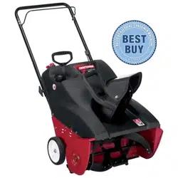
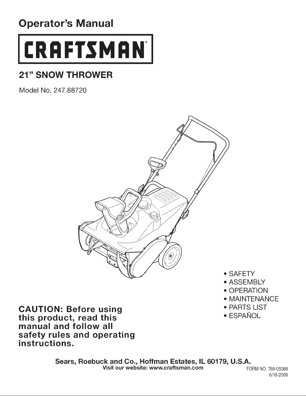
21" SNOW THROWER
Model No. 247.88720
CAUTION: Before using
this product, read this
manual and follow all
safety rules and operating
instructions.
o SAFETY
ASSEMBLY
OPERATION
MAINTENANCE
PARTS LIST
o ESPANOL
Sears, Roebuck and Co., Hoffman Estates, IL 60179, U.S.A.
Visit our website: www.craftsman.com FORM1/0. 769-05088
6/18/2009
WarrantyStatement..................................Pac
SafeOperationPractices..........................Pac
SafetyLabels............................................Pac
Assembly..................................................Pac
Operation..................................................Pac
ServiceandMaintenance.........................Pac
Off-SeasonStorage..................................Pac
e2
es3-5
e6
es7-9
es10-12
es13-17
e18
TroubleShooting.......................................Page19
PartsList...................................................Page20-27
Labels.......................................................Page28
RepairProtectionAgreement...................Page32
Espa_ol.....................................................Page33
ServiceNumbers......................................BackCover
CRAFTSMANFULLWARRANTY
Whenoperatedandmaintainedaccordingtoallsuppliedinstructions,ifthisCraftsmansnowthrowerfailsduetoa
defectin materialorworkmanshipwithintwoyearsfromthedateofpurchase,returnitto anySearsstore,SearsParts
& RepairServiceCenter,orotherCraftsmanoutletintheUnitedStatesforfreerepair(orreplacementif repairproves
impossible).
Thiswarrantyappliesforonly90daysfromthedateof purchaseifthischipper-shredderiseverusedforcommercialor
rentalpurposes.
This warranty covers ONLY defects in material and workmanship. Sears will NOT pay for:
• Expendable items that become worn during normal use, including but not limited to
auger blades or paddles, skid shoes, shave plate, shear pins, spark plug, air cleaner, belts, and oil filter.
Standard maintenance servicing, oil changes, or tune-ups.
Tire replacement or repair caused by punctures from outside objects, such as nails, thorns, stumps, or glass.
Tire or wheel replacement or repair resulting from normal wear, accident, or improper operation or maintenance.
Repairs necessary because of operator abuse, including but not limited to damage caused by over-speeding the
engine, or from impacting objects that bend the auger, frame or crankshaft.
Repairs necessary because of operator negligence, including but not limited to, electrical and mechanical damage
caused by improper storage, failure to use the proper grade and amount of engine oil, or failure to maintain the
equipment according to the instructions contained in the operator's manual.
Engine (fuel system) cleaning or repairs caused by fuel determined to be contaminated or oxidized (stale). In
general, fuel should be used within 30 days of its purchase date.
Normal deterioration and wear of the exterior finishes, or product label replacement.
This warranty applies only while this product is within the United States.
This warranty gives you specific legal rights, and you may also have other rights which vary from state to state.
Sears, Roebuck and Co., Hoffman Estates, IL 60179
EngineOilType: SAE5W-30
EngineOilCapacity: 20ounces
FuelCapacity: 2 Quarts
SparkPlug: TorchF6RTC
SparkPlugGap: .020"-.030"
Model Number.................................................................
Serial Number .................................................................
Dateof Purchase .............................................................
Recordthe modelnumber,serialnumber
anddateof purchaseabove
© Sears Brands,LLC
2
Thissymbolpointsout importantsafetyinstructionswhich,if not
followed,couldendangerthepersonalsafetyand/orpropertyof
yourselfandothers. Readand followall instructionsin thismanual
beforeattemptingto operatethismachine.Failureto complywith
theseinstructionsmay resultin personalinjury.Whenyou seethis
symbol,HEEDITSWARNING!
CALIFORNIA PROPOSITION 65
EngineExhaust,someof itsconstituents,and certainvehicle
componentscontainoremitchemicalsknownto Stateof California
to cause cancerand birthdefectsorotherreproductiveharm,
Thismachinewasbuiltto beoperatedaccordingto the safeopera-
tion practicesin this manual.As withanytype of powerequipment,
carelessnessor error on the partof the operatorcan resultin serious
injury.Thismachineis capableof amputatingfingers,hands,toes
andfeetandthrowingdebris.Failureto observethe followingsafety
instructionscouldresultin seriousinjuryor death.
Your Responsibility--Restrict the useof this powermachineto
personswho read,understandandfollowthewarningsand instruc-
tionsin thismanualandon the machine,
SAVE THESE INSTRUCTIONS!
TRAiNiNG
• Read,understand,andfollowall instructionson the machineand
in themanual(s)beforeattemptingto assembleandoperate.
Failureto do socan resultinseriousinjuryto the operatorand/
orbystanders.Keepthismanualin a safeplaceforfutureand
regularreferenceandfor orderingreplacementparts. Forques-
tionscall,1-800-4MY-HOME.
• Befamiliarwithall controlsandtheir properoperation.Knowhow
to stop the machineanddisengagethemquickly.
Neverallowchildrenunder 14 yearsof ageto operatethis
machine.Children14andover shouldreadandunderstandthe
instructionsand safe operationpracticesin this manualand on
the machineand be trainedand supervisedby anadult.
Neverallowadultsto operatethis machinewithoutproper
instruction.
• Thrownobjectscan causeseriouspersonalinjury.Planyour
snow-throwingpatternto avoiddischargeof materialtoward
roads,bystandersandthe like.
Keepbystanders,pets and childrenat least75 feet from the
machinewhile itisin operation.Stopmachineifanyoneenters
the area.
Exercisecautionto avoidslippingor falling,especiallywhen
operatinginreverse.
PREPARATION
Thoroughlyinspecttheareawherethe equipmentis to beused.
Removeall doormats,newspapers,sleds,boards,wiresandother
foreignobjects,whichcouldbe trippedoverorthrownby the auger/
impeller.
Alwayswear safetyglassesor eyeshieldsduringoperationand
while performingan adjustmentor repairto protectyoureyes.
Thrownobjectswhich ricochetcancauseseriousinjuryto the
eyes.
Donot operatewithoutwearingadequatewinteroutergarments.
Donot wearjewelry,long scarvesor otherlooseclothing,which
could becomeentangledin movingparts.Wearfootwearwhich
will improvefooting on slipperysurfaces.
Usea groundedthree-wireextensioncordand receptaclefor all
machineswith electricstartengines.
Disengageall controlleversbeforestartingthe engine.
Neverattemptto make anyadjustmentswhileengineis running,
exceptwherespecificallyrecommendedinthe operator'smanual.
Letengineand machineadjustto outdoortemperaturebefore
startingto clearsnow.
3
Safe Handling of Gasoline
Toavoidpersonalinjuryor propertydamageuseextremecare in
handlinggasoline.Gasolineis extremelyflammableandthe vaporsare
explosive.Seriouspersonalinjurycan occurwhengasolineis spilled
onyourselfor yourclotheswhichcan ignite.Washyour skinand
changeclothesimmediately.
• Useonly anapprovedgasolinecontainer.
• Extinguishall cigarettes,cigars,pipesand other sources
of ignition.
• Neverfuelmachineindoors.
• Neverremovegas capor add fuel whilethe engineis hot
or running.
• Allowengine to coolat leasttwo minutesbeforerefueling.
• Neveroverfill fueltank. Filltankto no morethan1/2inch
belowbottomof filler neckto providespacefor fuel
expansion.
• Replacegasolinecap andtightensecurely.
• If gasolineis spilled,wipeit offthe engineand equipment.
Movemachineto anotherarea.Wait5 minutesbefore
startingthe engine.
• Neverstorethe machineor fuel containerinsidewhere
thereis anopenflame,sparkor pilotlight (e.g.furnace,
waterheater,spaceheater,clothesdryer etc.).
• Allowmachineto cool at least5 minutesbeforestoring.
• Neverfill containersinsidea vehicleor ona truckor trailer
bedwitha plasticliner.Alwaysplacecontainersonthe
groundawayfromyourvehicle beforefilling.
• If possible,removegas-poweredequipmentfrom thetruck
ortrailerand refuelit on the ground.If this is not possible,
then refuelsuch equipmenton a trailerwitha portable
container,ratherthan fromagasolinedispensernozzle.
• Keepthe nozzleincontactwiththe rimof the fueltankor
containeropeningat all timesuntil fuelingis complete.Do
notuse a nozzlelock-opendevice.
OPERATION
• Do not puthandsorfeetnear rotatingparts,in the auger/impeller
housingor chuteassembly.Contactwith the rotatingpartscan
amputatehandsandfeet.
• Theauger/impellercontrolleveris a safetydevice.Neverbypass
itsoperation.Doingso makesthe machineunsafeand may cause
personalinjury.
• Thecontrol leversmustoperateeasilyin bothdirectionsand
automaticallyreturnto the disengagedpositionwhenreleased.
• Neveroperatewith a missingor damagedchuteassembly.Keep
all safetydevicesin placeand working.
• Neverrunanengineindoorsor ina poorlyventilatedarea. Engine
exhaustcontainscarbonmonoxide,anodorlessanddeadlygas.
• Do notoperatemachinewhileunderthe influenceof alcoholor
drugs.
• Mufflerandenginebecomehotand can causea burn.Do not
touch.Keepchildrenaway.
• Exerciseextremecautionwhenoperatingon or crossinggravel
surfaces.Stay alertfor hiddenhazardsor traffic.
• Exercisecautionwhenchangingdirectionand whileoperatingon
slopes.
• Planyoursnow-throwingpatternto avoiddischargetowards
windows,walls,cars etc. Thus,avoidingpossibleproperty
damageor personalinjurycausedby a ricochet.
• Neverdirect dischargeat children,bystandersand petsor allow
anyonein front of the machine.
• Donot overloadmachinecapacityby attemptingto clearsnowat
too fastof a rate.
• Neveroperatethis machinewithoutgoodvisibilityorlight.Always
be sureof yourfootingand keepa firm hold on the handles.Walk,
neverrun.
• Disengagepowerto theauger/impellerwhentransportingor not
in use.
• Neveroperatemachineat high transportspeedson slippery
surfaces.Lookdownand behindand usecare whenbackingup.
• If the machineshouldstart to vibrateabnormally,stop the engine,
disconnectthe spark plugwire andgroundit againstthe engine.
Inspectthoroughlyfor damage.Repairanydamagebefore
startingand operating.
• Disengageall controlleversand stop enginebeforeyouleave
the operatingposition(behindthe handles).Waituntilthe auger/
impellercomesto a completestop beforeuncloggingthechute
assembly,makingany adjustments,or inspections.
• Neverput yourhand in the dischargeor collectoropenings.Do
not unclogchuteassemblywhileengineis running.Shutoff
engineand remainbehindhandlesuntilall movingparts have
stoppedbeforeunclogging.
• Useonly attachmentsandaccessoriesapprovedby the manufac-
turer (e.g.wheelweights,tire chains,cabsetc.).
• Whenstartingengine,pullcord slowlyuntilresistanceis felt, then
pull rapidly.Rapidretractionof startercord(kickback)will pull
handandarmtowardenginefasterthan youcan let go. Broken
bones,fractures,bruisesor sprainscould result.
• If situationsoccur whichare notcoveredinthis manual,use care
andgoodjudgment.ContactCustomerSupportfor assistance
andthe nameof your nearestservicingdealer.
CLEARING A CLOGGED DISCHARGE CHUTE
Handcontactwith the rotatingimpellerinsidethe dischargechute
is the mostcommoncauseof injuryassociatedwithsnowthrowers.
Neveruse yourhandto cleanout thedischargechute.
Toclear thechute:
1. SHUTTHE ENGINEOFF!
2. Wait 10secondsto be surethe impellerbladeshavestopped
rotating.
3. Alwaysusea clean-outtool, not yourhands.
4
MAINTENANCE & STORAGE
• Nevertamperwith safetydevices.Checktheirproperoperation
regularly.Referto the maintenanceand adjustmentsectionsof
thismanual.
• Beforecleaning,repairing,or inspectingmachinedisengageall
controlleversandstopthe engine.Wait untilthe auger/impeller
cometo a completestop.Disconnectthe sparkplug wireand
groundagainsttheengineto preventunintendedstarting.
Checkboltsand screwsfor propertightnessat frequentintervals
to keepthe machinein safe workingcondition.Also, visually
inspectmachinefor anydamage.
Do notchangetheenginegovernorsettingor over-speedthe
engine.Thegovernorcontrolsthe maximumsafeoperatingspeed
of the engine.
Snowthrowershaveplatesand skid shoesare subjectto wear
anddamage.Foryoursafetyprotection,frequentlycheckall
componentsand replacewith originalequipmentmanufacturer's
(OEM)parts only.Use of partswhichdo not meetthe original
equipmentspecificationsmayleadto improperperformanceand
compromisesafety!
Checkcontrolleversperiodicallyto verifythey engageanddisen-
gageproperlyand adjust,if necessary.Referto the adjustment
sectioninthis operator'smanualfor instructions.
Maintainor replacesafetyand instructionlabels,as necessary.
• Observeproperdisposallawsand regulationsfor gas,oil,etc. to
protectthe environment.
Priorto storing,run machinea few minutestoclear snowfrom
machineand preventfreezeupof auger/impeller.
Neverstorethe machineor fuel containerinsidewherethereisan
openflame,spark orpilot lightsuch as a waterheater,furnace,
clothesdryer etc.
Alwaysreferto the operator'smanualfor properinstructionson
off-seasonstorage.
Checkfuelline,tank, cap,andfittingsfrequentlyfor cracksor
leaks.Replaceif necessary.
Do notcrankenginewithsparkplugremoved.
Accordingto the ConsumerProductsSafetyCommission(CPSC)
andthe U.S.EnvironmentalProtectionAgency(EPA),thisproduct
hasan AverageUsefulLifeof seven(7)years,or 60 hoursof
operation.At the endof theAverageUsefulLifehavethe machine
inspectedannuallybyan authorizedservicedealerto ensurethat
allmechanicalandsafetysystemsareworkingproperlyand not
wornexcessively.Failureto do so can resultinaccidents,injuries
ordeath.
DO NOT MODIFY ENGINE
Toavoidseriousinjuryor death,do not modifyengine in any way.
Tamperingwiththe governorsettingcanlead to a runawayengineand
causeit to operateat unsafespeeds.Nevertamperwithfactorysetting
of engine governor.
NOTICE REGARDING EMiSSiONS
Engineswhich are certifiedtocomplywithCaliforniaandfederal
EPAemissionregulationsfor SORE(SmallOff RoadEquipment)are
certifiedto operateon regularunleadedgasoline,and mayinclude
the followingemissioncontrol systems:EngineModification(EM),
OxidizingCatalyst(OC), SecondaryAirInjection(SAI)and ThreeWay
Catalyst(TWO)if so equipped.
SPARK ARRESTOR
Thismachineisequippedwith an internalcombustionengineand
shouldnotbe usedon or nearany unimprovedforest-covered,
brush-coveredor grass-coveredland unlessthe engine'sexhaust
systemisequippedwitha sparkarrestermeetingapplicablelocalor
statelaws (if any)
Ifa sparkattesteris used, it shouldbe maintainedin effectiveworking
orderby theoperator.Inthe Stateof Californiathe aboveis required
bylaw (Section4442of the CaliforniaPublicResourcesCode). Other
statesmayhavesimilarlaws. Federallawsapplyonfederallands.
A sparkarresterfor the muffleris availablethroughyournearestSears
PartsandRepairServiceCenter.
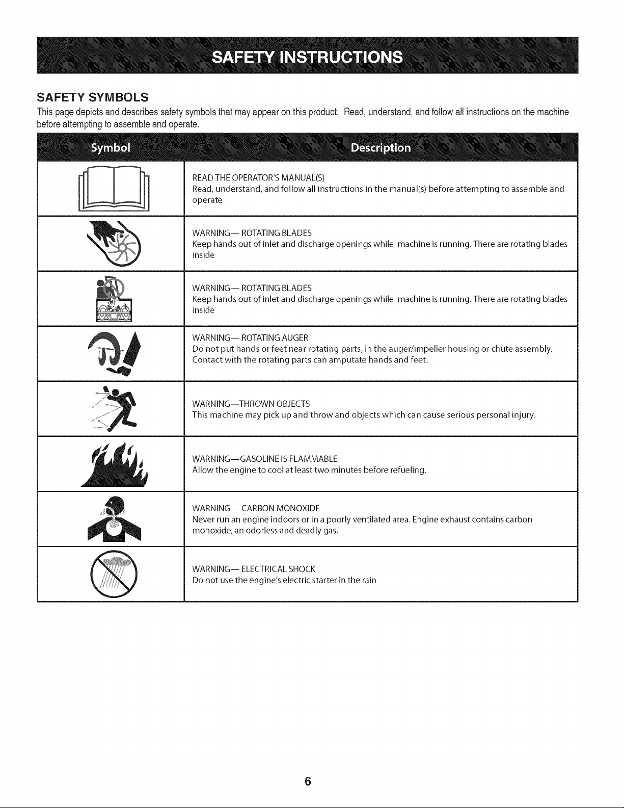
SAFETY SYMBOLS
Thispagedepictsand describessafetysymbolsthatmayappearonthis product. Read,understand,andfollowall instructionson the machine
beforeattemptingto assembleandoperate.
i
i
READ THE OPERATOR'S MANUAL(S)
Read, understand, and follow all instructions in the manual(s) before attempting to assemble and
operate
WARNING-- ROTATING BLADES
Keep hands out of inlet and discharge openings while machine is running. There are rotating blades
inside
WARNING-- ROTATING BLADES
Keep hands out of inlet and discharge openings while machine is running. There are rotating blades
inside
WARNING-- ROTATING AUGER
Do not put hands or feet near rotating parts, in the auger/impeller housing or chute assembly.
Contact with the rotating parts can amputate hands and feet.
WARNING--THROWN OBJECTS
This machine may pick up and throw and objects which can cause serious personal injury.
WARNING--GASOLINE IS FLAMMABLE
Allow the engine to cool at least two minutes before refueling.
WARNING-- CARBON MONOXIDE
Never run an engine indoors or in a poorly ventilated area. Engine exhaust contains carbon
monoxide, an odorless and deadly gas.
WARNING-- ELECTRICAL SHOCK
Do not use the engine's electric starter in the rain
6
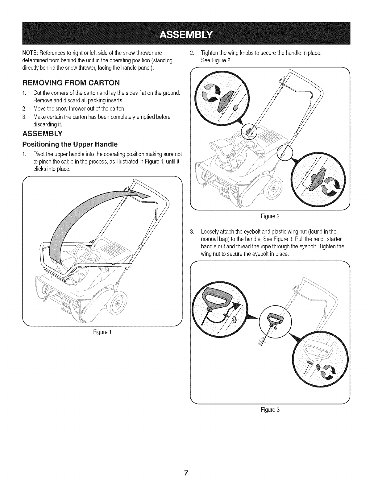
NOTE:Referencesto rightorleft sideof the snowthrowerare
determinedfrombehindthe unit inthe operatingposition(standing
directlybehindthe snowthrower,facingthe handlepanel).
2. Tightenthe wingknobs to securethe handleinplace.
See Figure2.
REMOVING FROM CARTON
1. Cut the cornersof thecartonandlay the sidesflaton the ground.
Removeand discard all packinginserts.
2. Movethe snowthrowerout of thecarton.
3. Makecertainthe cartonhas beencompletelyemptiedbefore
discardingit.
ASSEMBLY
Positioning the Upper Handle
1. Pivotthe upperhandleintothe operatingpositionmakingsurenot
to pinchthe cablein the process,as illustratedin Figure1,untilit
clicksintoplace.
.
Figure2
Looselyattachthe eyeboltandplasticwing nut (foundin the
manualbag)to the handle.See Figure3. Pullthe recoilstarter
handleout and threadthe ropethroughthe eyebolt.Tightenthe
wing nutto securethe eyeboltin place.
Figure1
Figure3
7
SET-UP
Fuel Recommendations
Useautomotivegasoline(unleadedor low leadedto minimizecombus-
tionchamberdeposits)with a minimumof 87octane.Gasolinewith
upto 10%ethanolor 15%MTBE(MethylTertiaryButylEther)can be
used.Neveruse an oil/gasolinemixtureor dirty gasoline.Avoidgetting
dirt,dust,or waterin the fueltank. DONOT use E85 gasoline.
• Refuelina well-ventilatedareawiththe enginestopped.Donot
smokeor allowflamesor sparksinthe area wherethe engineis
refueledor wheregasolineis stored.
Do notoverfillthe fuel tank.After refueling,make surethetank
cap is closedproperlyand securely.
Becarefulnot to spill fuelwhen refueling.Spilledfuel or fuelvapor
mayignite.Ifany fuel isspilled,makesurethe area isdry before
startingthe engine.
Avoidrepeatedor prolongedcontactwithskinor breathingof
vapor.
Adding Fuel
I Use care handlinggasoline, extremely
extreme when Gasolineis
flammableand thevaporsare explosive.Neverfuel the machine
indoorsorwhilethe engineishotor running.Extinguishcigarettes,
cigars,pipesandothersourcesof ignition.
Alwayskeephandsand feet clearof equipmentmovingparts. Donot
use a pressurizedstartingfluid. Vaporsare flammable.
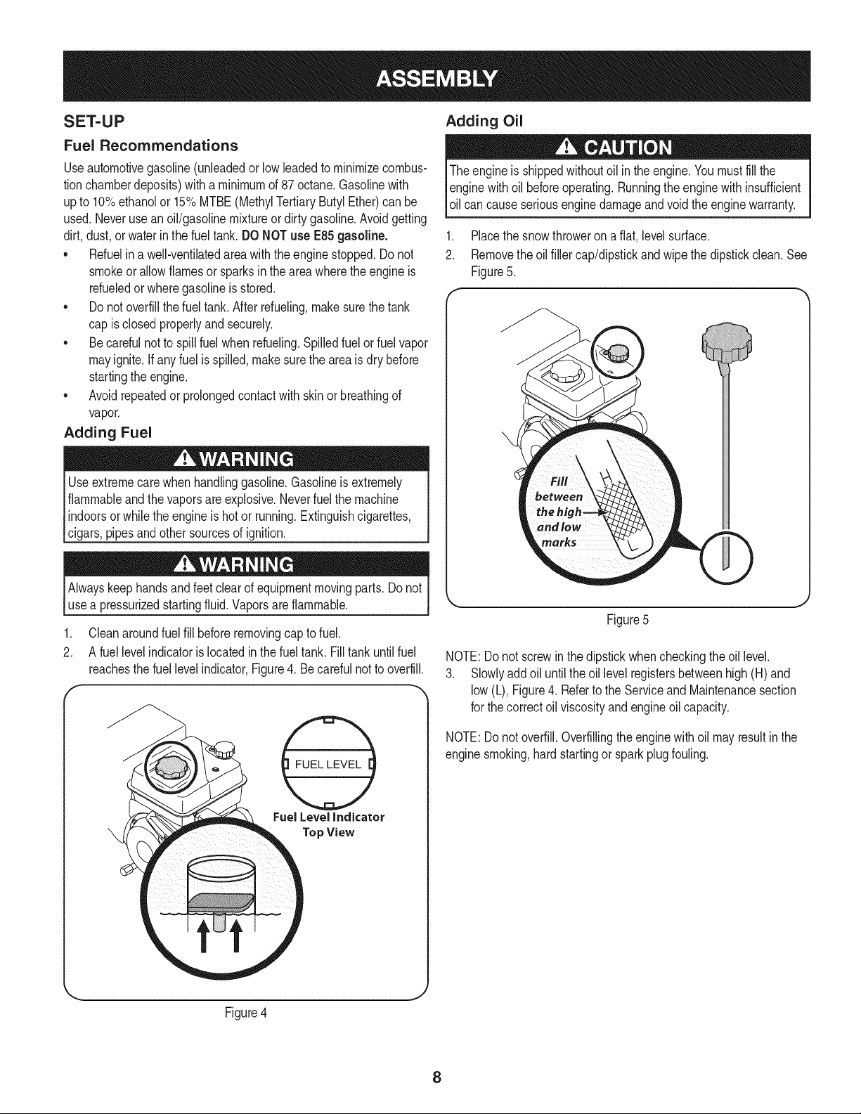
1. Cleanaroundfuel fill beforeremovingcapto fuel.
2. A fuellevelindicatorislocatedinthefuel tank. Filltankuntilfuel
reachesthe fuel levelindicator,Figure4. Becarefulnot to overfill.
(
Fuel Level indicator
Top View
Adding Oil
The engineis shippedwithoutoil inthe engine.You mustfill the
enginewithoil beforeoperating.Runningthe enginewith insufficient
_o cancause serous engne damageandvod the eng ne warranty.
1. Placethe snowthrowerona flat, levelsurface.
2. Removethe oilfiller cap/dipstickand wipe thedipstickclean.See
Figure5.
Figure5
NOTE:Do not screwin thedipstickwhencheckingtheoil level.
3. Slowlyaddoil untilthe oil levelregistersbetweenhigh(H)and
low(L), Figure4. Referto the ServiceandMaintenancesection
for the correctoil viscosityand engineoil capacity.
NOTE:Do notoverfill.Overfillingtheengine with oil may resultinthe
enginesmoking,hardstartingor sparkplugfouling.
Figure4
J
8
ADJUSTMENTS
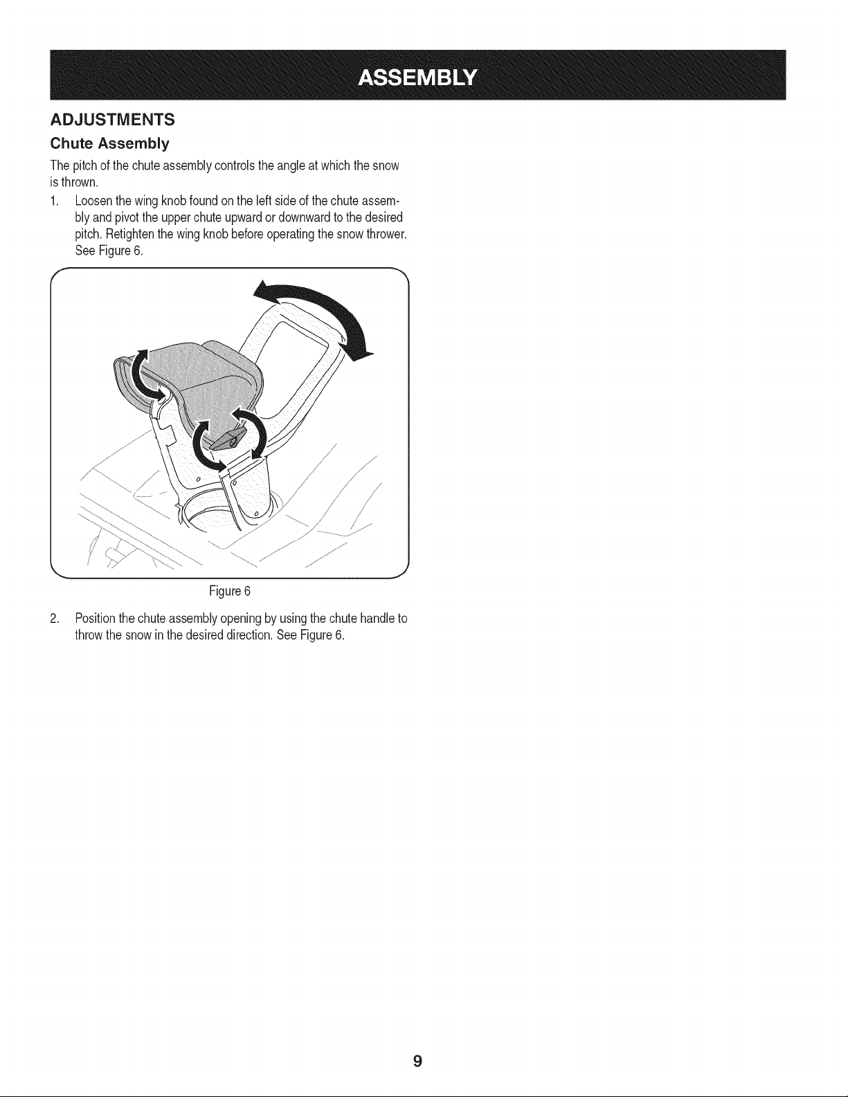
Chute Assembly
The pitchof the chuteassemblycontrolsthe angleat whichthe snow
is thrown.
1. Loosenthe wingknobfoundon the leftside of thechuteassem-
bly and pivotthe upperchuteupwardor downwardto the desired
pitch.Refightenthe wing knobbeforeoperatingthe snowthrower.
SeeFigure6,
F
.
Figure6
J
Positionthe chute assemblyopeningby usingthe chutehandleto
throwthe snow in the desireddirection.See Figure6.
9
Aug
Recoil Starter_
Handle
Gasoline Cap
Chute
Assembly
Engine
Primer
\
Key
/
Throttle
Control
Choke
Control
Sta rter
Figure7
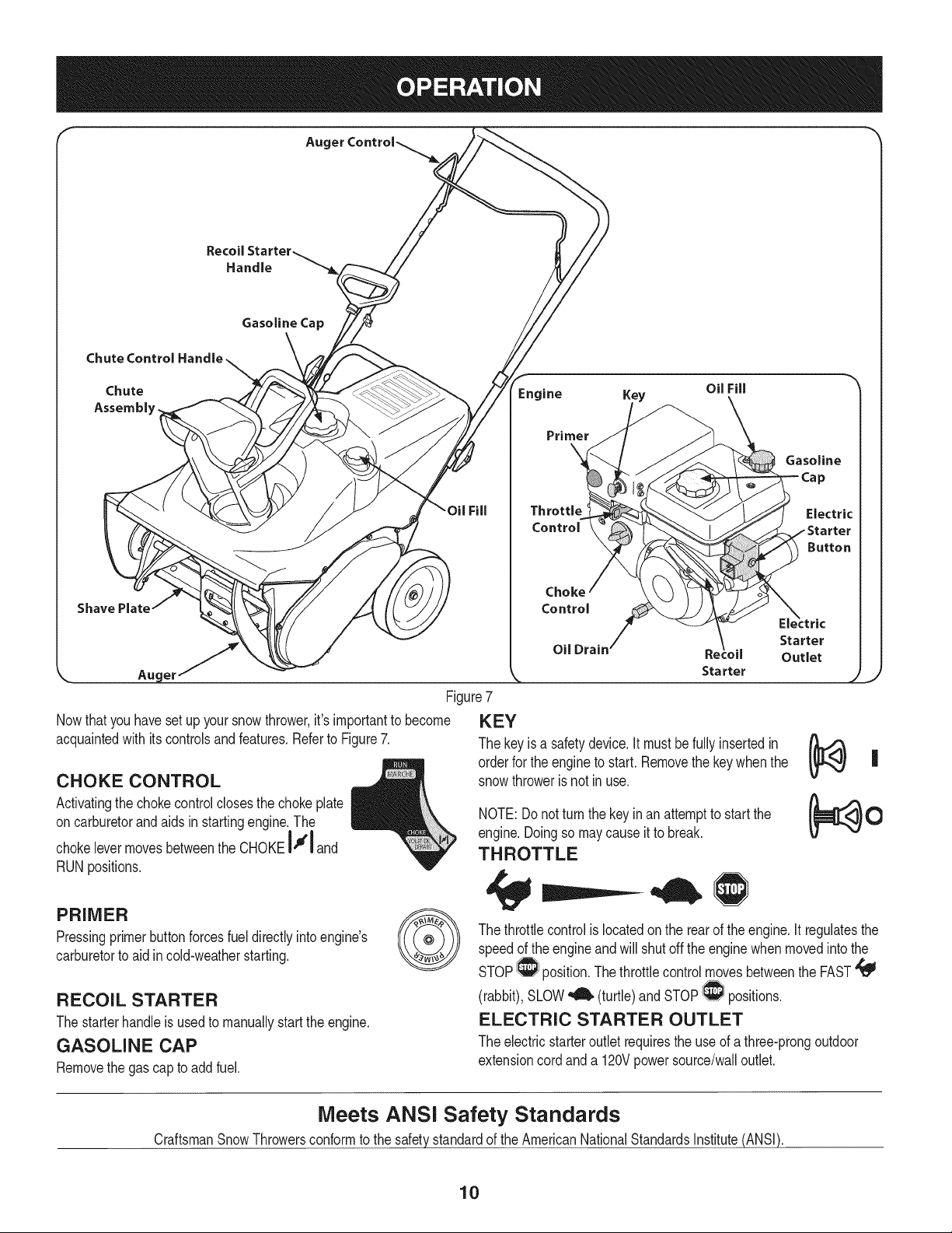
Nowthat youhavesetup yoursnowthrower,it's importantto become
acquaintedwith itscontrolsandfeatures.Referto Figure7.
CHOKE CONTROL
Activatingthe chokecontrolclosesthe chokeplate
oncarburetorandaids in startingengine.The
chokelevermovesbetweenthe CHOKEi,'41 and
RUNpositions.
PRIMER
Pressingprimerbuttonforcesfuel directlyintoengine's
carburetorto aid in cold-weatherstarting.
RECOIL STARTER
The starterhandle is usedto manuallystart theengine.
GASOLINE CAP
Removethe gas cap to add fuel.
KEY
The key is a safetydevice.It mustbefullyinsertedin
orderfor theengineto start. Removethe key whenthe
snowthroweris not inuse.
NOTE:Do notturn the key in an attemptto startthe
engine.Doingso maycause it to break.
THROTTLE
m.-.-
Gasoline
Electric
Button
Starter
Outlet
The throttlecontrolis locatedon the rearof the engine.It regulatesthe
speedof the engineandwill shutoffthe enginewhenmovedinto the
STOP_ position.Thethrottlecontrolmovesbetweenthe FAST'_
(rabbit),SLOW_ (turtle)and STOP_ positions.
ELECTRIC STARTER OUTLET
The electricstarteroutletrequiresthe useof a three-prongoutdoor
extensioncordanda 120Vpowersource/walloutlet.
Meets ANSi Safety Standards
CraftsmanSnowThrowersconformto the safetystandardof the AmericanNationalStandardsInstitute(ANSi).
10
AUGER
Whenengaged,the auger rotationdraws snowintothe auger housing
andthrowsit out thedischargechute.Rubberpaddlesonthe auger
alsoaid in propellingthe snowthroweras they come in contactwith
the pavement.
AUGER CONTROL
Locatedon the upperhandle,the augercontrolhandleis usedto
engageanddisengagedriveto the auger.Squeezethe controlhandle
againstthe upperhandleto engagethe auger;releaseit to disengage.
CHUTE ASSEMBLY
Rotatethe dischargechuteto the leftor rightusingthe chute handle.
Thepitch of the dischargechute controlsthe angleat whichthe snow
is thrown.Loosenthewing knobonthe side of the dischargechute
beforepivotingthe dischargechuteupwardor downward.Retighten
the knoboncethe desiredpositionhasbeen achieved.
SHAVE PLATE
Theshaveplate maintainscontactwith the pavementas the snow
throweris propelled,allowingsnowclose tothe pavement'ssurfaceto
bedischarged.
ELECTRIC STARTER BUTTON
Pressingthe electricstarterbuttonengagesthe engine'selectric
starterwhenpluggedintoa 120Vpowersource.
NOTE:The electricstarteris mountedto the plasticshroudandis
shownin Figure7 attachedto the enginefor easierreference.
BEFORE STARTING THE ENGINE
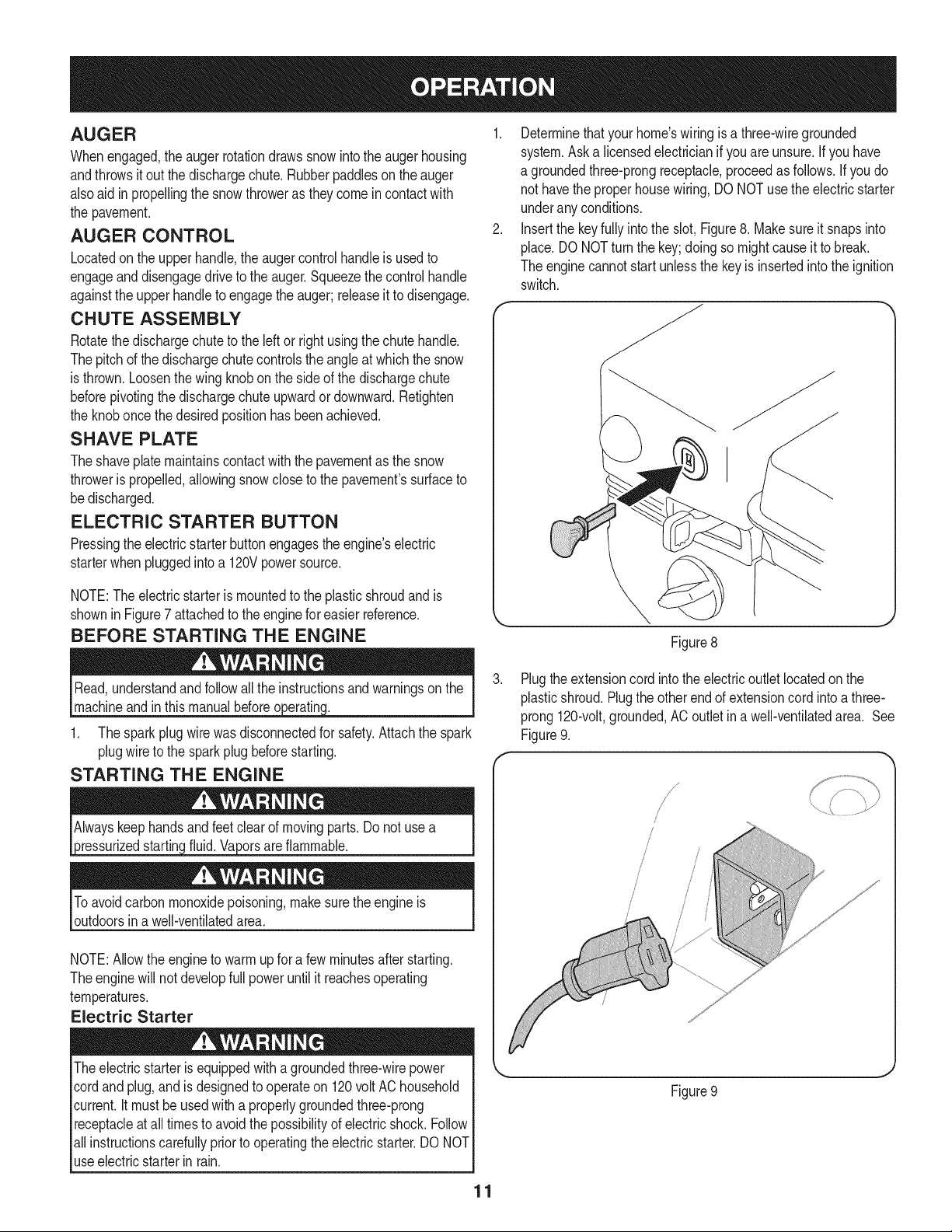
1. Determinethatyour home'swiringis a three-wiregrounded
system.Aska licensedelectricianif youare unsure.If youhave
a groundedthree-prongreceptacle,proceedas follows.Ifyou do
nothavethe properhousewiring, DO NOTusethe electricstarter
underanyconditions.
2. Insertthe keyfully intothe slot, Figure8. Makesureit snapsinto
place.DO NOTturnthe key;doingso mightcause it to break.
The enginecannotstart unlessthe keyis insertedintothe ignition
switch.
Figure8
machineandin thismanual
1. Thesparkplugwirewas disconnectedfor safety.Attachthe spark
plugwireto the spark plug beforestarting.
STARTING THE ENGINE
_ressurizedstartin( areflammable.
To avoidcarbonmonoxidepoisoning,makesuretheengineis
outdoorsina well-ventilatedarea.
NOTE:Allowthe engineto warmupfor a fewminutesafter starting.
Theenginewill not developfull poweruntilit reachesoperating
temperatures.
Electric Starter
Theelectricstarteris equippedwithagroundedthree-wirepower
cordand plug,andis designedto operateon 120volt AC household
current.It mustbe usedwith a properlygroundedthree-prong
receptacleatall timesto avoidthe possibilityof electricshock. Follow
all instructionscarefullyprior to operatingthe electricstarter.DO NOT
useelectricstarterin rain.
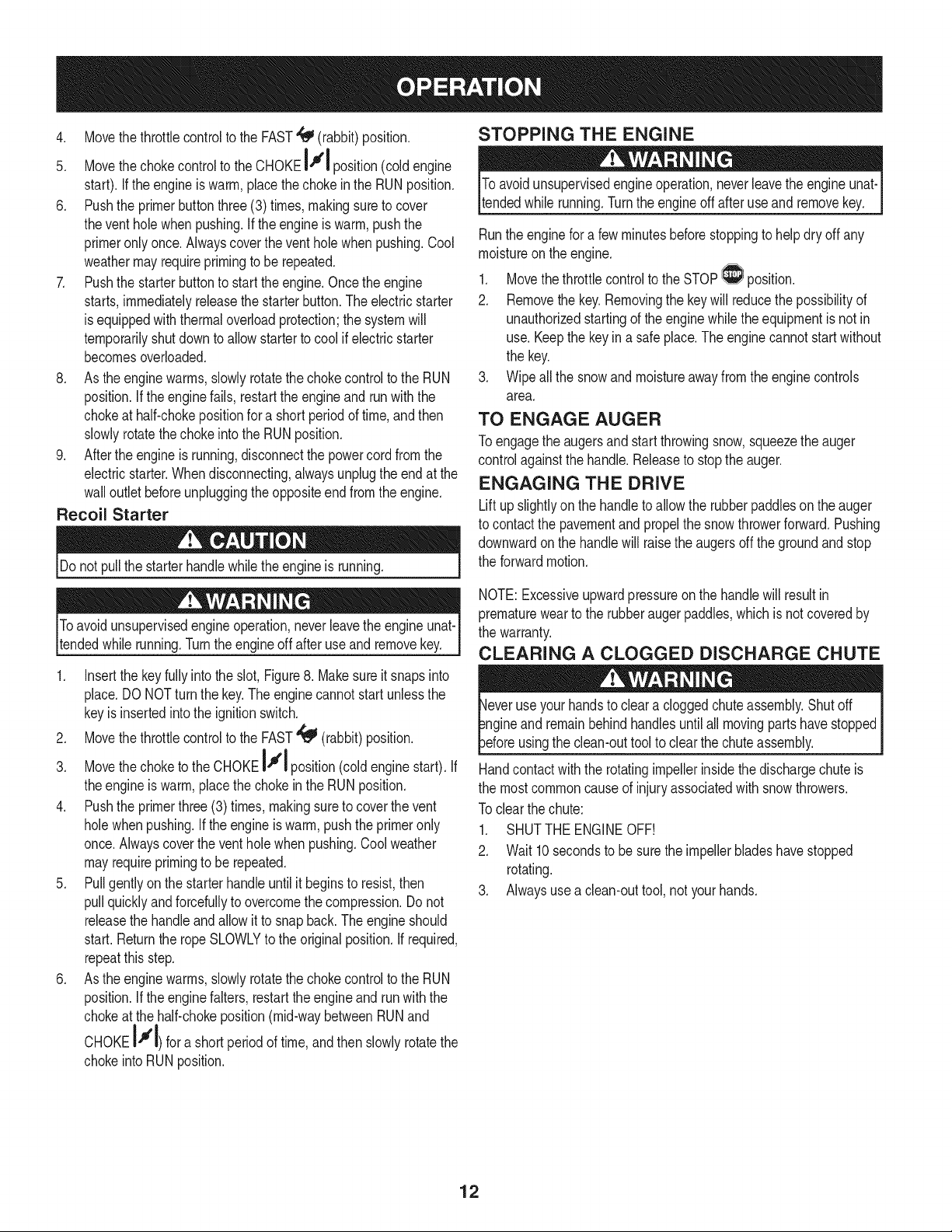
Plugthe extensioncord intothe electricoutletlocatedon the
plasticshroud.Plugthe other endof extensioncord intoa three-
prong120-volt,grounded,ACoutletina well-ventilatedarea. See
Figure9.
Figure9
11
4. Movethe throttlecontrolto the FAST41_(rabbit)position.
5. Movethe chokecontrolto the CHOKEI,,'1po, t on<co dengine
start).Ifthe engine is warm,placethe chokeinthe RUNposition.
6. Pushthe primerbutton three(3) times,makingsureto cover
thevent hole when pushing.If theengineis warm,pushthe
primeronly once.Alwayscover theventholewhenpushing.Cool
weathermayrequireprimingto be repeated.
7. Pushthe starterbuttonto start theengine.Oncetheengine
starts,immediatelyreleasethestarterbutton.Theelectricstarter
is equippedwith thermaloverloadprotection;the systemwill
temporarilyshut downto allowstarterto cool if electricstarter
becomesoverloaded.
8. As theengine warms,slowlyrotatethe chokecontrolto the RUN
position.If the enginefails,restartthe engineand run with the
chokeat half-chokepositionfor a shortperiodof time,and then
slowlyrotatethechokeintothe RUNposition.
9. Afterthe engineis running,disconnectthe powercord fromthe
electricstarter.Whendisconnecting,alwaysunplugthe end at the
walloutlet beforeunpluggingthe oppositeendfromthe engine.
Recoil Starter
Do not pullthe starterhandlewhile theengineis running.
Toavoidunsupervisedengineoperation,neverleavethe engineunat-
tendedwh e runnng. Turnthe engneoff afteruseand removekey. j
1. Insertthe key fully intothe slot, Figure8. Make sureit snaps into
place.DO NOTturn the key.The enginecannotstart unlessthe
keyis insertedintothe ignitionswitch.
2. Movethe throttlecontrolto the FAST_ (rabbit)position.
3. Movethe choketo the CHOKEIJl position(coldenginestart). If
theengine is warm,placethechoke in the RUNposition.
4. Pushthe primerthree (3)times,makingsureto coverthe vent
holewhenpushing.If the engineis warm,pushthe primeronly
once.Alwayscoverthe ventholewhenpushing.Coolweather
mayrequireprimingto be repeated.
5. Pull gentlyon the starterhandle untilit beginsto resist,then
pullquicklyand forcefullyto overcomethe compression.Do not
releasethe handleandallowit to snapback.Theengine should
start.Returnthe rope SLOWLYto the originalposition.If required,
repeatthis step.
6. As theengine warms,slowlyrotatethe chokecontrolto the RUN
position.If the enginefalters,restarttheengineand runwiththe
chokeat the half-chokeposition(mid-waybetweenRUNand
| I
CHOKEIII)for ashortperiodoftime,andthenslowlyrotatethe
chokeinto RUNposition.
STOPPING THE ENGINE
To unsupervisedengineoperation,never engine
avoid leavethe unat-
tendedwh e runnng.Turnthe engne off after use andremovekey. j
Runtheenginefora few minutesbeforestoppingto help dry off any
moistureon theengine.
1. Movethethrottlecontrolto the STOP_ position.
2. Removethe key.Removingthe keywill reducethe possibilityof
unauthorizedstartingof the enginewhilethe equipmentis not in
use.Keepthe key in a safeplace.The enginecannotstartwithout
the key.
3. Wipeall the snowand moistureawayfrom the enginecontrols
area.
TO ENGAGE AUGER
Toengagethe augersandstartthrowingsnow,squeezethe auger
controlagainstthe handle.Releaseto stop the auger.
ENGAGING THE DRIVE
Liftupslightlyon the handleto allowthe rubber paddleson the auger
to contactthe pavementand propelthe snowthrowerforward.Pushing
downwardonthe handlewill raisethe augersoffthe groundandstop
the forwardmotion.
NOTE:Excessiveupwardpressureonthe handlewill resultin
prematurewearto the rubberauger paddles,which is notcoveredby
the warranty.
CLEARING A CLOGGED DISCHARGE CHUTE
lever handsto clear chute Shutoff [
use
your
a
clogged assembly.
gineand remainbehindhandlesuntilall movingparts havestopped[
II
fore usingthe clean-outtool to clearthe chuteassembly. J
Handcontactwith the rotatingimpellerinsidethe dischargechute is
the mostcommoncauseof injuryassociatedwithsnowthrowers.
Toclear thechute:
1. SHUTTHE ENGINEOFF!
2. Wait 10secondsto be surethe impellerbladeshavestopped
rotating.
3. Alwaysusea clean-outtool, not yourhands.
12
MAINTENANCE SCHEDULE
Beforeperforminganytypeof maintenance/service,disengageall
controlsand stoptheengine.Waituntilall movingpartshavecometo
acompletestop.Disconnectsparkplugwireandgrounditagainstthe
enginetopreventunintendedstarting.Alwayswearsafetyglassesduring
operationor whileperforminganyadjustmentsor repairs.
Followthe maintenanceschedulegivenbelow.This chart describes
serviceguidelinesonly. Usethe ServiceLogcolumnto keeptrackof
completedmaintenancetasks.To locate the nearest Sears Service
Centeror to scheduleservice,simplycontactSears at
1-800-4-MY-HOME®.
EachUse .
2.
1. Check
2. Clean
Engineoil level.
SnowThrowerand exhaust
area.
Engineoil.
Engineoil.
Exhaustarea.
SparkPlug.
Engineoil
Sparkplug
Pivotpoints
Controlhandle
Extensionspring
1st5 hours 1. 1. Change.
Every5 hours 1. 1. Check.
2. 2. Clean.
25hours 1. 2. Check.
Everyseason/50hours 1. 1. Change
Everyseason/lO0hours 1. 1. Clean,replace,re-gap
Everyseason/Before 1. 1. Lubricate
storage 2. 2. Lubricate
3. 3. Lubricate
ENGINE MAINTENANCE
Topreventaccidentalstart-up,shutoffthe engineand removethe
ignitionkey beforeperforminganytypeof engine maintenance.
Periodicinspectionand adjustmentof the engine is essentialif high
levelperformanceis to be maintained.Regularmaintenancewill also
ensurea long servicelife.The requiredserviceintervalsandthetype
of maintenanceto beperformedaredescribedinthe tableabove.
Followthe hourlyor calendarintervals,whicheveroccurfirst. More
frequentserviceis requiredwhenoperatingin adverseconditions.
CHECKING ENGINE OIL
1. Removethe oil fillercap/dipstickandwipethe dipstickclean.
Referto Figure4.
2. Insertthe cap/dipstickintothe oil filler neck,but DO NOTscrew
it in.
3. Removethe oil fillercap/dipstick.If the levelis low,slowlyadd
oil untiloil levelregistersbetweenhigh (H) andlow (L), Referto
Figure4.
NOTE:Donot overfill.Overfillingthe enginewithoil mayresultin the
enginesmoking,hardstartingorspark plug fouling.
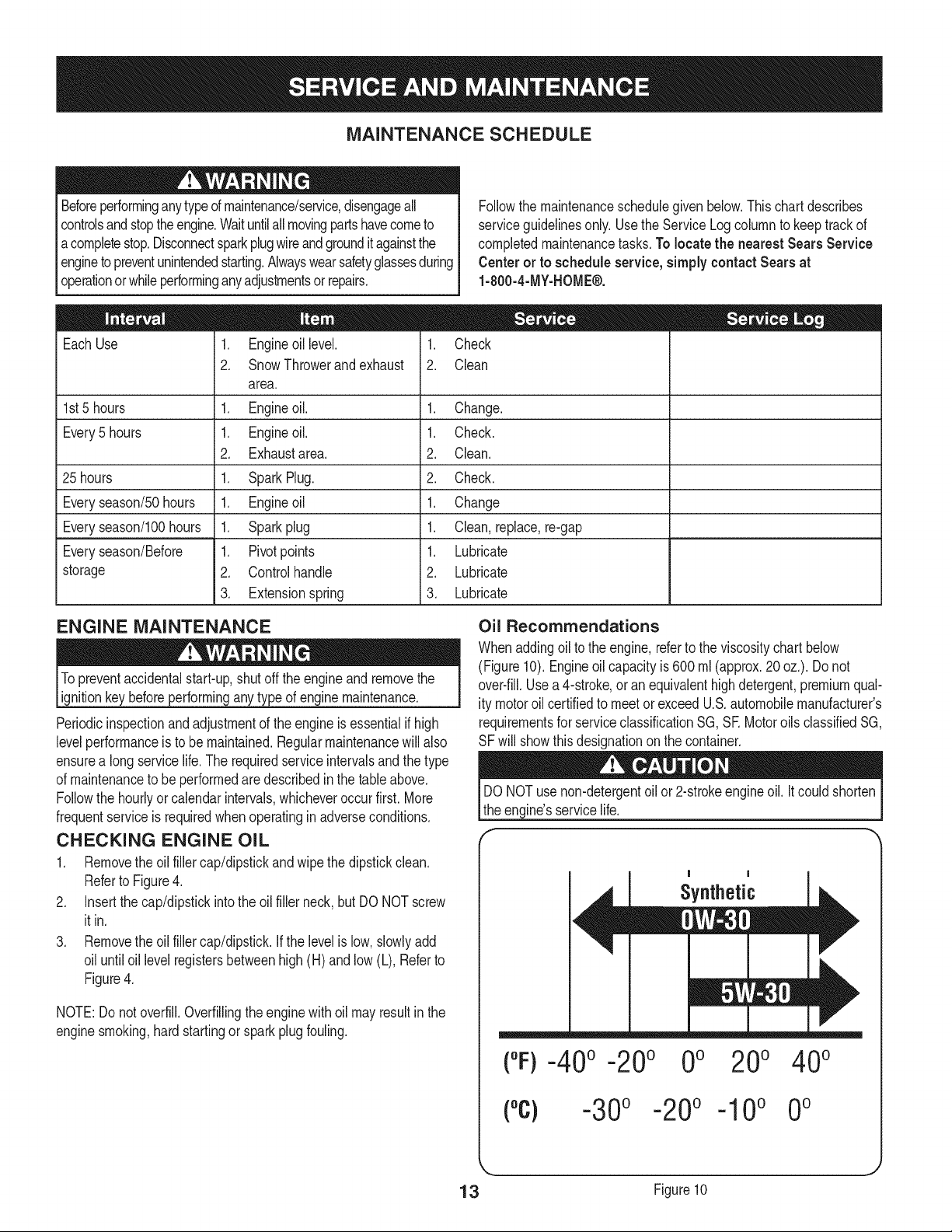
Oil Recommendations
Whenaddingoil to the engine,referto the viscositychartbelow
(Figure10). Engineoil capacityis 600 rnl (approx.20 oz.). Do not
over-fill.Usea4-stroke,oran equivalenthighdetergent,premiumqual-
itymotoroil certifiedto meetor exceedU.S.automobilemanufacturer's
requirementsfor serviceclassificationSG,SE Motoroils classifiedSG,
SF will showthisdesignationonthe container.
DONOT usenon-detergentoil or2-strokeengineoil. It couldshorten
the engine'sservicelife.
! I
Synthetic
(°F)-40o -20o 0o 200 400
("C) -30° -20° -10° 0°
13 Figure10
CHANGING ENGINE OiL SPARK PLUG
NOTE:The engineoil shouldbechangedafterthe first fivehoursof
useand then oncea seasonorafter 50 hoursof use. Checkthe oil
levelbeforeeach useandaftereveryfive hoursof operationto be sure
the correctoil levelismaintained.Referto CheckingEngineOil.
1. Drainfuelfromthe tank by runningtheengine untilthe fueltankis
empty.Besurethe fuel fill capis secure.
2. Placea suitableoil collectioncontainerunderthe oil drain plug.
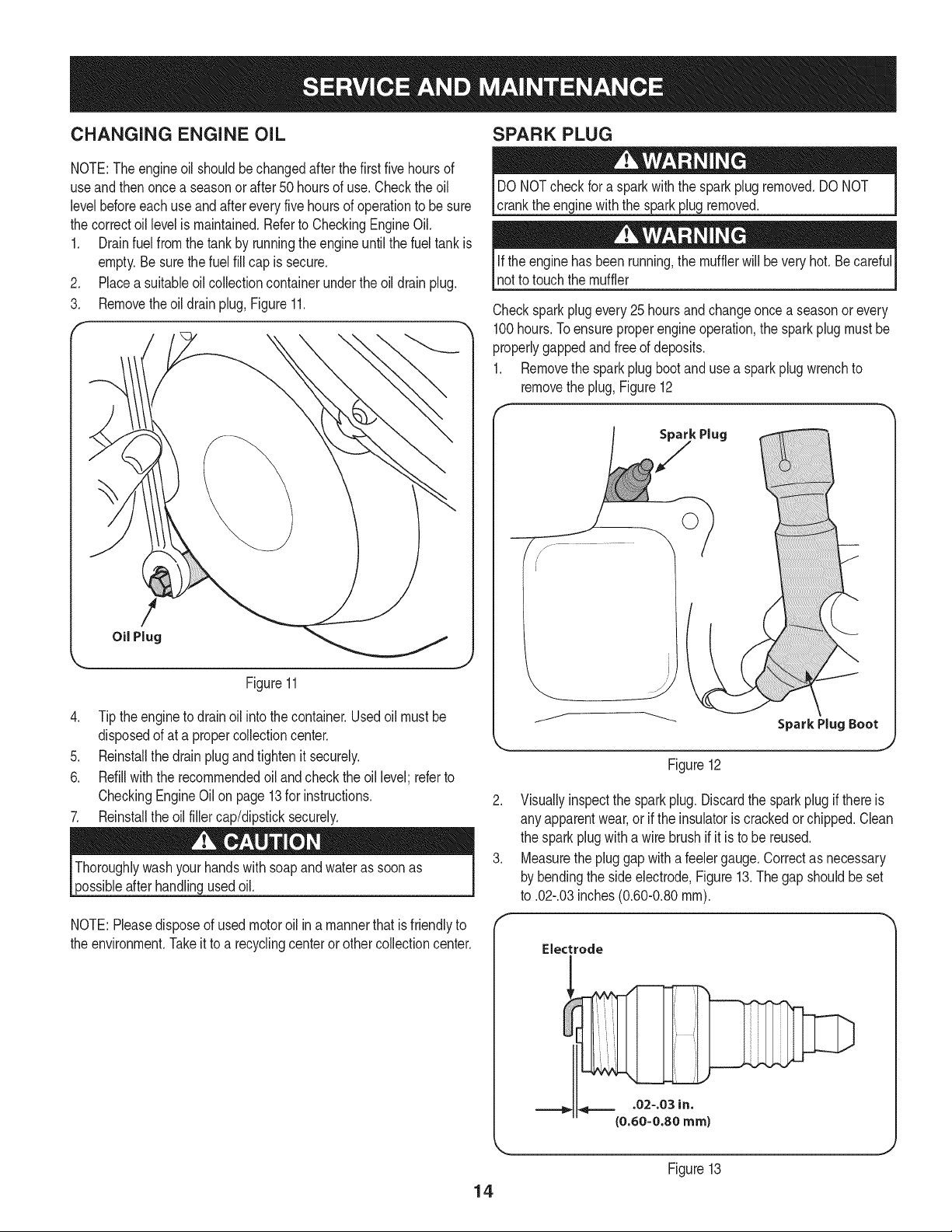
3. Removetheoil drainplug,Figure11.
!
OilPlug
Figure11
4. Tip theengineto drainoil intothe container.Usedoil mustbe
disposedof at a propercollectioncenter.
5. Reinstallthe drainplugandtightenit securely.
6. Refillwith the recommendedoil and checkthe oil level;referto
CheckingEngineOil on page 13for instructions.
7. Reinstallthe oilfillercap/dipsticksecurely.
Thoroughlywashyourhandswithsoapand wateras soon as
possibleafterhandlingusedoil.
DONOTcheck fora spark with the sparkplugremoved.DONOT
cranktheengine with the sparkplugremoved.
if the enginehas been running,the mufflerwill beveryhot. Becareful
not to touchthemuffler
Checkspark plugevery25 hoursandchangeoncea seasonorevery
100hours.Toensureproperengineoperation,the sparkplugmustbe
properlygappedand freeof deposits.
1. Removethe sparkplug bootand usea spark plugwrenchto
removethe plug,Figure12
SparkPlug
,J
©
I
Figure12
SparkPlugBoot
=J
2. Visuallyinspectthe sparkplug. Discardthe sparkplug if thereis
any apparentwear,or if the insulatoris crackedor chipped.Clean
the spark plugwith a wire brushifit isto be reused.
3. Measurethe pluggapwitha feelergauge.Correctas necessary
bybendingthe sideelectrode,Figure13.Thegap shouldbe set
to .02-.03inches(0.60-0.80mm).
NOTE:Pleasedisposeof usedmotoroil ina mannerthat isfriendlyto
the environment.Takeit to a recyclingcenteror othercollectioncenter.
Electrode
.02-.03 in.
(0.60=0.80 ram)
14
Figure13
4. Checkthatthesparkplugwasherisingoodconditionandthread 3.
thesparkpluginbyhandtopreventcross-threading.
5. Afterthesparkplugisseated,tightenwithasparkplugwrenchto
compressthewasher, f
NOTE:Wheninstallinganewsparkplug,tighten1/2-turnafterthe
sparkplugseatstocompressthewasher.Whenreinstallingaused
sparkplug,tighten1/8-to1/4-turnafterthesparkplugseatsto
corn_ressthewasher.
becomeverhotandcandarnac me.
CLEANING THE ENGINE
Ifthe engine hasbeenrunning,allowit to cool for at leasthalfan hour
beforecleaning.Periodicallyremovedirt build-upfromengine.
Do not spraythe enginewithwater to cleanit becausethewater
couldcontaminatethe fuel.Usinga gardenhoseor pressurewashing
Iequipmentcanalso forcewater intothe muffleropening.Waterthat
[passesthroughthe muffer can enterthecy nderandcausedamage,j
Accumulationof debrisaroundthe mufflercouldcausea fire. Inspect
andcleanbeforeevery use.
LUBRICATION
Lubricatethe pivot pointson the controlhandleandthe extension
springat the end of thecontrol cablewitha lightoil onceeveryseason
andbeforethe snowthroweris putinto storageatthe endof the
season.
ADJUSTMENTS
BeforeServicing,repairingor inspectingthe snowthrower,disengage
the augercontrol.Stop theengineand removethe key to prevent
unintendedstarting.
Shave Plate
Tocheckthe adjustmentof theshaveplate,placethe machineona
levelsurface.The wheels,shaveplateandaugerpaddlesshouldall
contactthe levelsurface.Notethatifthe shaveplateis adjustedtoo
high,snow mayblowundertheauger housing.If the shaveplatewears
outexcessively,orthe snowthrowerdoes notself-propel,the shave
platemay be too lowand needsto be adjusted.
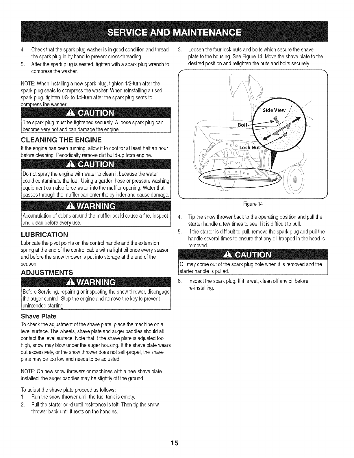
Loosenthefour lock nuts andbolts whichsecurethe shave
plateto the housing.SeeFigure14.Movethe shaveplateto the
desiredpositionand retightenthe nutsandboltssecurely.
L._
Figure14
4. Tip the snowthrowerback to theoperatingpositionandpullthe
starterhandlea few timesto see ifit isdifficultto pull.
5. Ifthe starterisdifficultto pull,removethe sparkplugand pullthe
handleseveraltimesto ensurethat anyoil trappedin the headis
removed.
Oilmaycomeout of the sparkplug hole whenit is removedand the
starterhandle ispulled.
6. Inspectthe sparkplug.If itiswet, cleanoffany oil before
re-installing.
NOTE:On newsnowthrowersor machineswitha newshaveplate
installed,theauger paddlesmay be slightlyoff theground.
Toadjustthe shaveplateproceedas follows:
1. Runthe snowthroweruntilthe fuel tankis empty.
2. Pull the startercord until resistanceisfelt. Thentip the snow
throwerbackuntil itrestson the handles.
15
Control Cable
As a resultof both thecontrolcableand the augerdrivebelt stretching
dueto wear,periodicadjustmentsmaybenecessary.Ifthe auger
seemsto hesitatewhenrotating,proceedas follows:
Theupper hole in the controlhandleprovidesfor an adjustmentin
cabletension.Toadjust,disconnectthe endof controlcablefrom the
bottomholein the controlhandleand reinsertit inthe upperhole.
Insertthe cablefrom theoutsideas shown in Figure15.
f
Control
Handle
/
Figure 15
Testthe snowthrowerto seeif there isa noticeabledifference.If
aftertheadjustmentto the controlcablethe augerstill hesitateswhen
rotating,see ReplacingBeltfor instructionson replacingthe belt.
Chute Assembly
Referto the AssemblySectionfor instructionson adjustingthe chute
assembly.
REPLACING BELT
Auger Drive Belt
1. Removethebelt coverby removingthe five hex screwsthat
secureitto the frame.SeeFigure16.
2. Removethe belt bygraspingit fromthebottomof the augerpulley
and pullingoutward.
NOTE:Pushdownon the idlerpulleyto releasethe belt fromunderthe
beltkeeper.See Figure16.
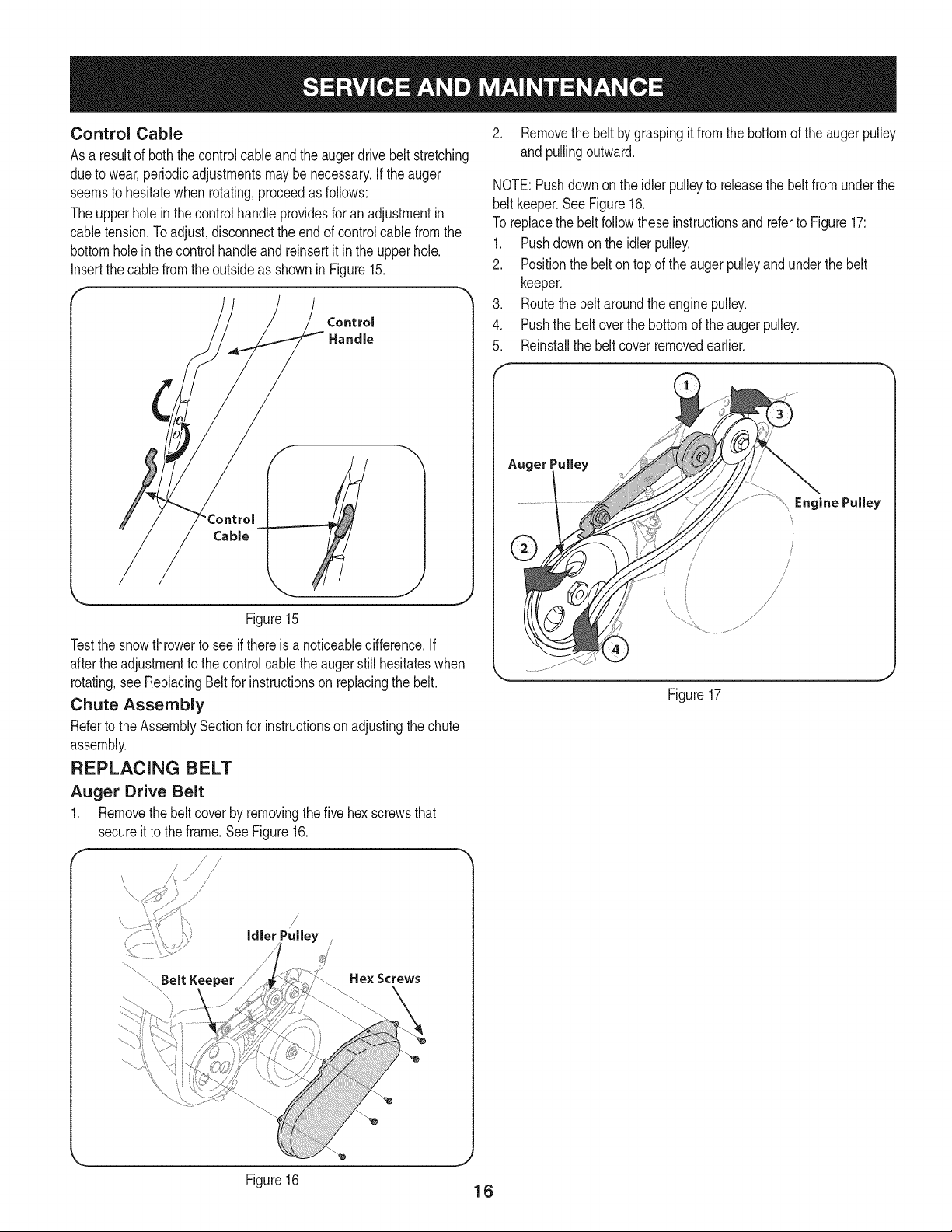
To replacethe beltfollow theseinstructionsand referto Figure17:
1. Pushdownon the idler pulley.
2. Positionthe belton topof theaugerpulleyand underthe belt
keeper.
3. Routethebelt aroundthe enginepulley.
4. Pushthe belt overthe bottomof the auger pulley.
5. Reinstallthe belt coverremovedearlier.
, Engine Pulley
/
/
/
i f /
Figure17
.........Belt Keeper
Figure16 16
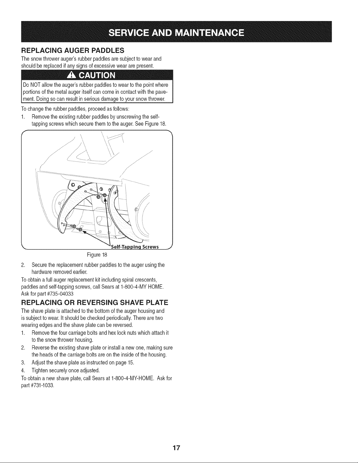
REPLACING AUGER PADDLES
The snowthrowerauger'srubberpaddlesare subjectto wearand
shouldbe replacedifany signsof excessivewearare present.
Do NOTallowthe auger'srubberpaddlesto wearto the pointwhere
portionsof the metalaugeritselfcancomein contactwiththe pave-
ment.Doingsocan resultin seriousdamageto yoursnowthrower.
Tochangethe rubberpaddles,proceedas follows:
1. Removethe existingrubberpaddlesby unscrewingthe self-
tappingscrewswhich securethemto theauger.SeeFigure18.
Self-Ta
Figure18
Screws
2. Securethe replacementrubberpaddlesto the augerusingthe
hardwareremovedearlier.
Toobtainafull auger replacementkitincludingspiralcrescents,
paddlesand self-tappingscrews,call Searsat 1-800-4-MYHOME.
Askfor part#735-04033
REPLACING OR REVERSING SHAVE PLATE
The shaveplateis attachedto the bottomof the augerhousingand
is subjectto wear.It shouldbe checkedperiodically.Thereare two
wearingedgesandthe shaveplatecanbe reversed.
1. Removethe four carriageboltsandhexlock nuts which attachit
to the snowthrowerhousing.
2. Reversethe existingshaveplateor installa newone,makingsure
the headsof thecarriageboltsareon the insideof the housing.
3. Adjustthe shaveplateas instructedon page15.
4. Tightensecurelyonceadjusted.
Toobtaina newshaveplate,call Searsat 1-800-4-MY-HOME.Askfor
part #731-1033.
17
Ifthe snowthrowerwillnot be usedfor30 daysor longer,or if it is the endof the snowseasonwhenthe lastpossibilityof snowis gone,the
equipmentneedsto bestoredproperly.Followstorageinstructionsbelowto ensuretop performancefrom the snowthrowerfor manymoreyears.
PREPARING THE ENGINE
Enginesstoredover30daysneedto be drainedof fuel to prevent
deteriorationandgumfrom formingin the fuel systemor on essential
carburetorparts.If thegasolinein yourenginedeterioratesduring
storage,youmayneedto havethe carburetor,andotherfuel system
components,servicedor replaced.
1. Removeall fuel fromthe tankby runningtheengineuntilit stops.
2. Changethe engineoil.
3. Removethe sparkplugandpourapproximately1oz.(30 ml)of
cleanengineoil intothe cylinder.Pullthe recoilstarterseveral
timesto distributethe oil,and reinstallthe sparkplug.
4. Cleandebrisfromaroundthe engine,and under,around,and
behindthe muffler.Applya light film of oilon anyareasthatare
susceptibleto rust.
5. Storeina clean,dry andwellventilatedareaawayfromany
appliancethat operateswith a flameor pilot light,such as a
furnace,waterheateror clothesdryer.Avoidany areawitha spark
producingelectricmotor,or wherepowertools are operated.
Neverstoresnowthrowerwithfuel in tank indoorsor in poorlyventi-
latedareas,wherefuel fumesmayreachan openflame,spark or pilol
lightas ona furnace,water heater,clothesdryer orgas appliance.
6. If possible,avoidstorageareaswith high humidity.
7. Keepthe enginelevelin storage.Tiltingthe engine can cause
fuelor oil leakage.
PREPARING SNOW THROWER
Ifthe snowthrowerwill not be usedfor 30 days or longer,followthe
instructionsbelow.
1. Storethe equipmentin aclean,dry area.
2. Ifstoringthe snowthrowerin anunventilatedarea,rustproofthe
metalpartsof the machinewitha lightoil or siliconecoating.
3. Cleanthe exteriorof the engineand the snowthrower.
4. Lubricatepivotpointsoncontrolhandleandextensionspringat
endof control cablewitha lightoil.
18
Beforeperforminganytypeof maintenance/service,disengageall controlsandstoptheengine.Waituntilall
movingpartshavecometoa completestop.Disconnectsparkplugwireandgroundit againsttheengineto
preventunintendedstarting.Alwayswearsafetyglassesduringoperationorwhileperforminganyadjustmentsor
repairs.
Thissectionaddresses minor service issues.To locatethe nearest Sears Service Centeror to scheduleservice,simplycontactSears
at 1-800-4-MY-HOME®.
Enginefailsto start 1. Fueltank empty,or stalefuel.
2. Blockedfuel line.
3. Keynot insertedallthe way.
4. Sparkplugwiredisconnected.
5. Faultysparkplug.
6. Enginenot primed.
1. Filltankwithcleanfreshgasoline.
2. Cleanfuel line.
3. insertkey all theway.
4. Connectwire to sparkplug.
5. Cleansparkplug,readjustgap,or replace.
6. Pushthe engineprimerbuttonthree(3) times
Enginerunningerratically/
inconsistentRPM(huntingor
surging)
7. Enginefloodedfromexcessivepriming.
8. Extensioncord notconnected(whenusing
electricstart button)
1. Enginerunningon choke.
2. Fuelline blocked,or stalefuel.
3. Wateror dirt infuel system.
4. Carburetoroutof adjustment.
5. Over-governedengine
1. Carburetoroutof adjustment.
1. Sparkplug wireloose.
2. Ventin gascap plugged.
1. Looseparts or damagedauger.
7. Wait at leastten minutesbeforestarting.
8. Connectone end of the extensioncordto the electric
starteroutletand the otherendto a three-prong
120-volt,grounded,AC outlet.
1. Movechoke controlto RUNposition.
2. Cleanfuel line and fill tankwithfresh,cleangasoline.
3. Runengine untilit stops.Refillwith fresh fuel.
4. Contacta SearsServiceCenter.
5. Contacta SearsServiceCenter.
1. Augercontrolcableoutof adjustment.
2. Augerdrive beltlooseor damaged.
1. Augercontrolcableoutof adjustment.
1. Chuteassemblyclogged.
2. Foreignobjectlodgedin auger.
3. Augercontrol cableoutof adjustment.
4. Auger beltlooseor damaged.
Engineoverheats 1. Contacta SearsServiceCenter.
Lossof power 1. Firmlyconnectspark plug wire.
2. Clearvent.
Excessivevibration 1. Stopengine immediatelyand disconnectspark plug
wire.Checkfor possibledamage.Tightenall bolts
andnuts. Repairas needed.If the problempersists,
takesnowthrowerto a SearsServiceCenter.
Snowthrowerfails to self- 1. Adjustaugercontrolcableas showninServiceand
propel Maintenancesection.
2. Replaceaugerdrivebelt.
Augercontinueto rotate 1. Adjustaugercontrolcableas showninServiceand
Maintenancesection.
Unitfailsto dischargesnow 1. Stopengineanddisconnectsparkplugwire.Cleanchute
andinsideofaugerhousingwithclean-outtoolor stick.
2. Stopengineimmediatelyanddisconnectthe spark
plugwire.Removeobject fromauger.
3. Adjustauger controlcable.
4. Replaceaugerbelt.
NEED MORE HELP?
Youll/":_'_d t[_e _0_swer _r_d more o_ _'r_s_s_!?emy[]ome co_'y_- I_:_rIree!
,, Find this and all your other product manuals online.
" Get answers from our team of home experts.
,, Get a personalized maintenance plan for your home.
Find information and tools to help with home projects.
ma_age_home
b_'e_g_t to you by Sea_s
19
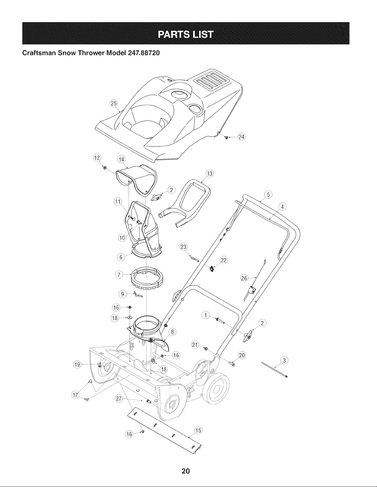
Craftsman Snow Thrower IViodel 247.88720
\
/
20
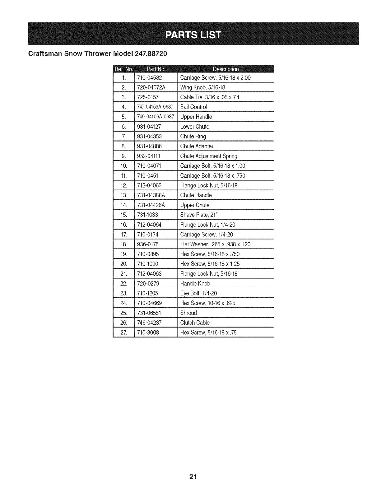
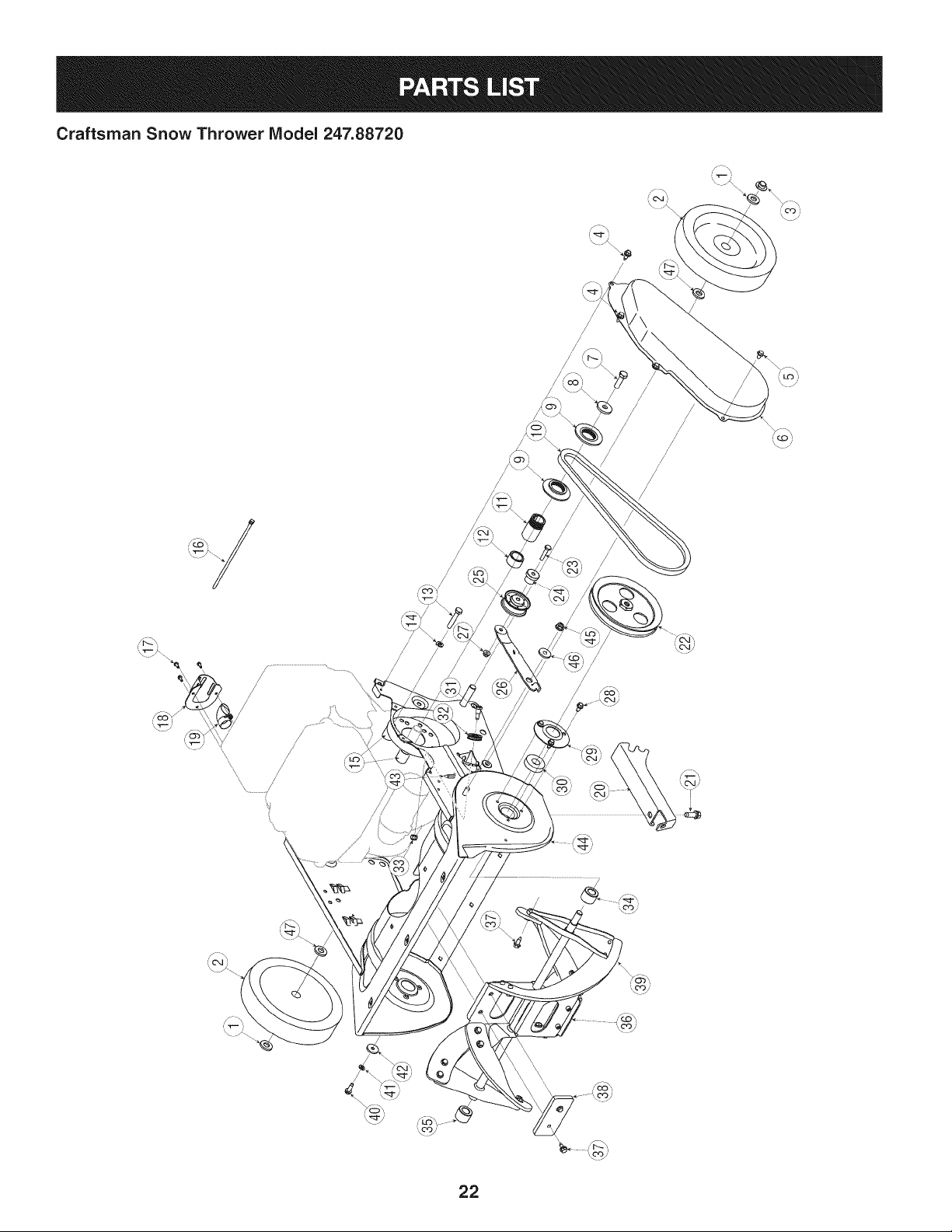
Craftsman Snow Thrower IViodel 247.88720
D = 0
710-04532 CarriageScrew,5/16-18x 2.00
2. 720-04072A Wing Knob,5/16-18
3. 725-0157 CableTie, 3/16 x .05x 7.4
4. 747-04159A-0637Bail Control
5. 749-04106A-0637UpperHandle
6. 931-04127 LowerChute
7. 931-04353 ChuteRing
8. 931-04886 ChuteAdapter
9. 932-04111 ChuteAdjustmentSpring
10. 710-04071 CarriageBolt.5/16-18x 1.00
11. 710-0451 CarriageBolt.5/16-18x .750
12. 712-04063 FlangeLock Nut,5/16-18
13. 731-04388A ChuteHandle
14. 731-04426A UpperChute
15. 731-1033 ShavePlate,21"
16. 712-04064 FlangeLock Nut, 1/4-20
17. 710-0134 CarriageScrew,1/4-20
18. 936-0176 FiatWasher,.265x .938x .120
19. 710-0895 HexScrew,5/16-18x .750
20. 710-1090 HexScrew,5/16-18x 1.25
21. 712-04063 FlangeLock Nut,5/16-18
22. 720-0279 HandleKnob
23. 710-1205 EyeBolt,1/4-20
24. 710-04669 HexScrew,10-16x .625
25. 731-06551 Shroud
26. 746-04237 ClutchCable
27. 710-3008 HexScrew,5/16-18x .75
21
Craftsman Snow Thrower IViodel 247.88720
/
/
/
/
/'
/
/
/
/
/
\T"\
/
/
/
/
/
/
/
/ /
/ ,//
/
\
22
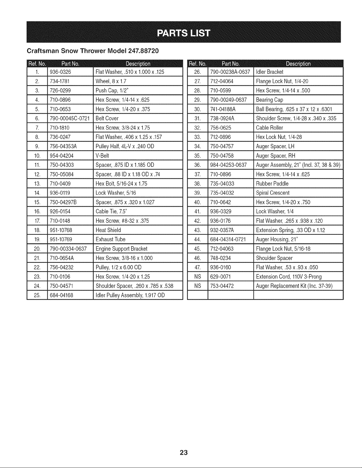
Craftsman Snow Thrower Model 247.88720
|- 0 e
936-0326 FiatWasher,.510x 1.000x .125
2. 734-1781 Wheel,8 x 1.7
3. L7260299 LPush Cap, 1/2"
4. 710-0896 HexScrew,1/4-14x .625
5. 710-0653 HexScrew,1/4-20x .375
6. 790-00045C-0721 BeltCover
7. 710-1810 HexScrew,3/8-24 x 1.75
8. 736-0247 FiatWasher,.406x 1.25x .157
9. 756-04353A PulleyHalf,4bV x .240OD
10. 954-04204 V-Belt
11. _ 750-04303 Spacer, .875ID x 1.185OD
12. 750-05084 Spacer,.88 IDx 1.18OD x .74
13. 710-0409 Hex Bolt,5/16-24x 1.75
14. 936-0119 LockWasher,5/16
15. 750-04297B Spacer,.875x .320x 1.027
16. 926-0154 CableTie, 7.5"
17. 710-0148 Hex Screw,#8-32x .375
18. 951-10768 HeatShield
19. 951-10769 ExhaustTube
20. 790-00334-0637
21. 710-0654A
22. 756-04232
23. 710-0106
24. 750-04571
25. 684-04168
EngineSupportBracket
HexScrew,3/8-16x 1.000
Pulley,1/2 x 6.00 OD
HexScrew,1/4-20x 1.25
ShoulderSpacer,.260x .785x .538
idlerPulleyAssembly,1.917OD
D = O 0
790-00238A-0637 IdlerBracket
27. 712-04064 FlangeLockNut, 1/4-20
28. 710-0599 HexScrew,1/4-14x .500
29. 790-00249-0637 BearingCap
30. 741-04188A Ball Bearing,.625x 37 x 12x .6301
31. 738-0924A ShoulderScrew,1/4-28x .340x .335
32. 756-0625 CableRoller
33. 712-0896 HexLockNut,1/4-28
34. 750-04757 AugerSpacer,LH
35. 750-04758 AugerSpacer,RH
36. 984-04253-0637 AugerAssembly,21"(Incl.37,38& 39)
37. 710-0896 Hex Screw,1/4-14x .625
38. 735-04033 RubberPaddle
39. 735-04032 SpiralCrescent
40. 710-0642 HexScrew,1/4-20x .750
41. 936-0329 LockWasher,1/4
42. 936-0176 FiatWasher,.265x .938x .120
43. 932-0357A ExtensionSpring,.33 ODx 1.12
44. 684-04314-0721 AugerHousing,21"
45. 712-04063 FlangeLockNut,5/16-18
46. 748-0234 ShoulderSpacer
47. 936-0160 FiatWasher,.53 x .93 x .050
NS 629-0071 ExtensionCord, 110V3-Prong
NS 753-04472 AugerReplacementKit (inc. 37-39)
23
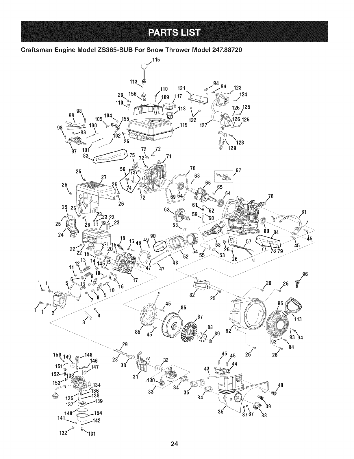
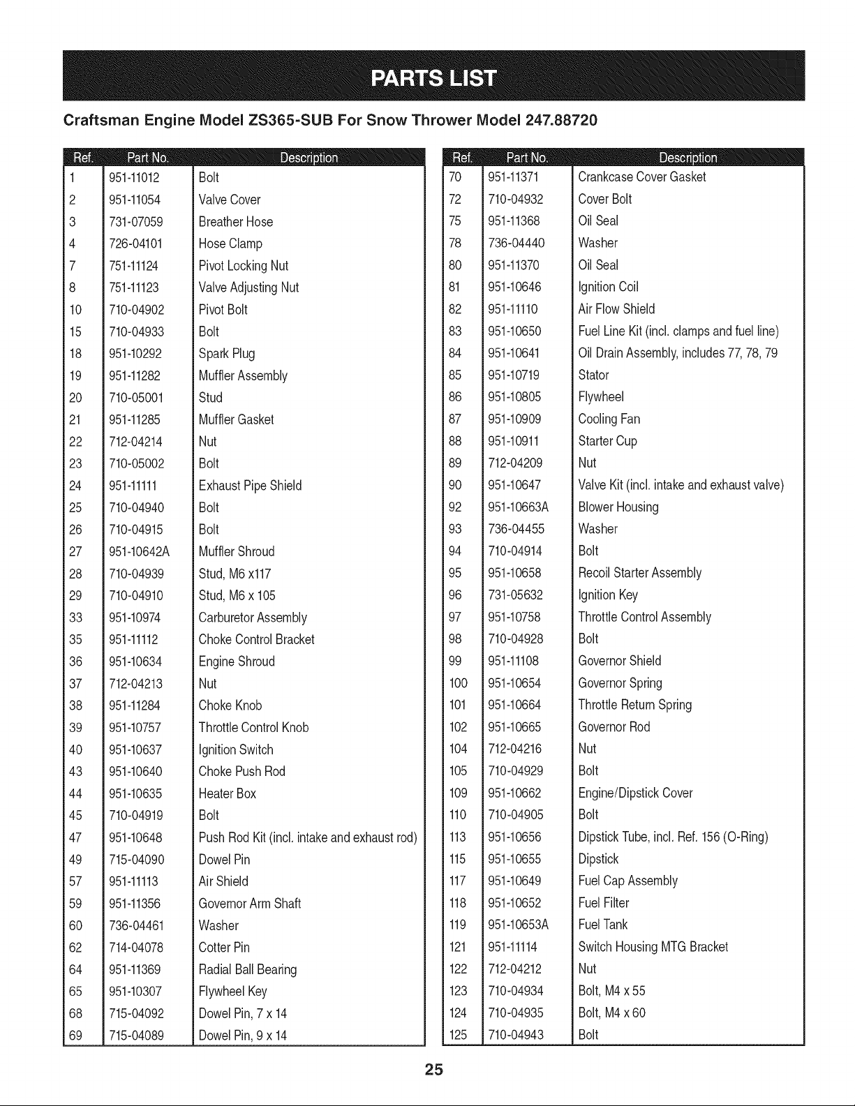
Craftsman Engine IViodel ZS365=SUB For Snow Thrower IViodel 247.88720
56
/ 66
65
_/ 64
76
72 /
81
/
1/
150 149 /148
\° o\ _ 146
13b _ ,,,,,
140/_.1154
132/® _\131
29 \
94
26/_ 26/_
45 45
32 _/ /44
43 /
\
40
/
34
39
X
38
24
Craftsman Engine IViodel ZS365=SUB For Snow Thrower IViodel 247.88720
1
2
3
4
7
8
10
15
18
19
20
21
22
23
24
25
26
27
28
29
33
35
36
37
38
39
40
43
44
45
47
49
57
59
60
62
64
65
68
69
951-11012
951-11054
731-07059
726-04101
751-11124
751-11123
710-04902
710-04933
951-10292
951-11282
710-05001
951-11285
712-04214
710-05002
951-11111
710-04940
710-04915
951-10642A
710-04939
710-04910
951-10974
951-11112
951-10634
712-04213
951-11284
951-10757
951-10637
951-10640
951-10635
710-04919
951-10648
715-04090
951-11113
951-11356
736-04461
714-04078
951-11369
951-10307
715-04092
715-04089
Bolt
ValveCover
BreatherHose
HoseClamp
PivotLockingNut
ValveAdjustingNut
PivotBolt
Bolt
SparkPlug
MufflerAssembly
Stud
MufflerGasket
Nut
Bolt
ExhaustPipe Shield
Bolt
Bolt
MufflerShroud
Stud,M6x117
Stud,M6x 105
CarburetorAssembly
ChokeControlBracket
EngineShroud
Nut
ChokeKnob
ThrottleControlKnob
IgnitionSwitch
ChokePushRod
HeaterBox
Bolt
PushRod Kit(incl. intakeand exhaustrod)
DowelPin
Air Shield
GovernorArm Shaft
Washer
CotterPin
RadialBall Bearing
FlywheelKey
DowelPin,7 x 14
DowelPin,9 x 14
70
72
75
78
8O
81
82
83
84
85
86
87
88
89
90
92
93
94
95
96
97
98
99
100
101
102
104
105
109
110
113
115
117
118
119
121
122
123
124
125
951-11371
710-04932
951-11368
736-04440
951-11370
951-10646
951-11110
951-10650
951-10641
951-10719
951-10805
951-10909
951-10911
712-04209
951-10647
951-10663A
736-04455
710-04914
951-10658
731-05632
951-10758
710-04928
951-11108
951-10654
951-10664
951-10665
712-04216
710-04929
951-10662
710-04905
951-10656
951-10655
951-10649
951-10652
951-10653A
951-11114
712-04212
710-04934
710-04935
710-04943
CrankcaseCoverGasket
CoverBolt
OilSeal
Washer
OilSeal
IgnitionCoil
AirFlowShield
FuelLine Kit (incl.clampsand fuel line)
OilDrainAssembly,includes77,78,79
Stator
Flywheel
CoolingFan
StarterCup
Nut
ValveKit (incl.intakeandexhaustvalve)
BlowerHousing
Washer
Bolt
RecoilStarterAssembly
IgnitionKey
ThrottleControlAssembly
Bolt
GovernorShield
GovernorSpring
ThrottleReturnSpring
GovernorRod
Nut
Bolt
Engine/DipstickCover
Bolt
DipstickTube,incl.Ref.156(O-Ring)
Dipstick
FuelCapAssembly
FuelFilter
FuelTank
SwitchHousingMTG Bracket
Nut
Bolt,M4x 55
Bolt,M4x 60
Bolt
25
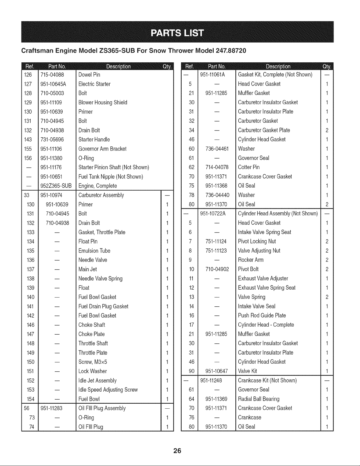
Craftsman Engine IViodel ZS365-SUB For Snow Thrower IViodel 247.88720
|= 0 o e
126 715-04088 DowelPin
127 951-10645A ElectricStarter
128 710-05003 Bolt
129 951-11109 BlowerHousingShield
130 951-10639 Primer
131 710-04945 Bolt
132 710-04938 Drain Bolt
143 731-05696 Starter Handle
155 951-11106 GovernorArm Bracket
156 951-11380 O-Ring
-- 951-11176 StarterPinionShaft(NotShown)
-- 951-10651 FuelTankNipple(NotShown)
-- 952Z365-SUB Engine,Complete
33 951-10974 CarburetorAssembly
130 951-10639 Primer 1
131 710-04945 Bolt 1
132 710-04938 Drain Bolt 1
133 -- Gasket,ThrottlePlate 1
134 -- Float Pin 1
135 -- EmulsionTube 1
136 -- NeedleValve 1
137 -- MainJet 1
138 -- NeedleValveSpring 1
139 -- Float 1
140 -- FuelBowlGasket 1
141 -- FuelDrain PlugGasket 1
142 -- FuelBowlGasket 1
146 -- ChokeShaft 1
147 -- ChokePlate 1
148 -- ThrottleShaft 1
149 -- ThrottlePlate 1
150 -- Screw,M3x5 1
151 -- LockWasher 1
152 -- Idle JetAssembly 1
153 -- Idle SpeedAdjustingScrew 1
154 -- Fuel Bowl 1
56 951-11283 Oil Fill PlugAssembly
73 -- O-Ring 1
74 -- Oil Fill Plug 1
D = O
-- 951-11061A GasketKit,Complete(Not Shown) --
5 -- HeadCoverGasket 1
21 951-11285 MufflerGasket 1
30 -- CarburetorInsulatorGasket 1
31 -- CarburetorInsulatorPlate 1
32 -- CarburetorGasket 1
34 -- CarburetorGasketPlate 2
46 -- CylinderHeadGasket 1
60 736-04461 Washer 1
61 -- GovernorSeal 1
62 714-04078 CotterPin 1
70 951-11371 CrankcaseCoverGasket 1
75 951-11368 OilSeal 1
78 736-04440 Washer 1
80 951-11370 OilSeal 2
-- 951-10722A CylinderHeadAssembly(Not Shown) --
5 -- HeadCoverGasket 1
6 -- IntakeValveSpringSeat 1
7 751-11124 PivotLockingNut 2
8 751-11123 ValveAdjustingNut 2
9 -- RockerArm 2
10 710-04902 PivotBolt 2
11 -- ExhaustValveAdjuster 1
12 -- ExhaustValveSpringSeat 1
13 -- ValveSpring 2
14 -- IntakeValveSeal 1
16 -- PushRodGuide Plate 1
17 -- CylinderHead- Complete 1
21 951-11285 MufflerGasket 1
30 -- CarburetorInsulatorGasket 1
31 -- CarburetorInsulatorPlate 1
46 -- CylinderHeadGasket 1
90 951-10647 ValveKit 1
-- 951-11248 CrankcaseKit(Not Shown) --
61 -- GovernorSeal 1
64 951-11369 RadialBall Bearing 1
70 951-11371 CrankcaseCoverGasket 1
76 -- Crankcase 1
80 951-11370 OilSeal 1
26
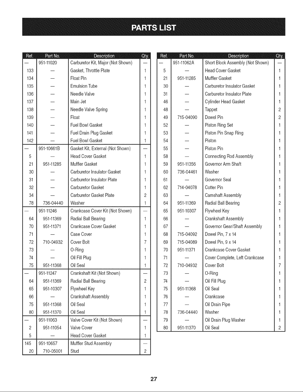
D" O O
-- 951-11020 CarburetorKit, Major(NotShown) --
133 -- Gasket,ThrottlePlate 1
134 -- FloatPin 1
135 -- EmulsionTube 1
136 -- NeedleValve 1
137 -- MainJet 1
138 -- NeedleValveSpring 1
139 -- Float 1
140 -- Fuel BowlGasket 1
141 -- Fuel DrainPlugGasket 1
142 -- Fuel BowlGasket 1
-- 951-10661B GasketKit,External(NotShown) --
5 -- HeadCoverGasket 1
21 951-11285 MufflerGasket 1
30 -- CarburetorInsulatorGasket 1
31 -- CarburetorInsulatorPlate 1
32 -- CarburetorGasket 1
34 -- CarburetorGasketPlate 2
78 736-04440 Washer 1
-- 951-11246 CrankcaseCoverKit (NotShown) --
64 951-11369 RadialBall Bearing 1
70 951-11371 CrankcaseCoverGasket 1
71 -- CaseCover 1
72 710-04932 CoverBolt 7
73 -- O-Ring 1
74 -- Oil Fill Plug 1
75 951-11368 Oil Seal 1
-- 951-11247 CrankshaftKit (NotShown) --
64 951-11369 RadialBall Bearing 2
65 951-10307 FlywheelKey 1
66 -- CrankshaftAssembly 1
75 951-11368 Oil Seal 1
80 951-11370 Oil Seal 1
-- 951-11063 ValveCoverKit (Not Shown) --
2 951-11054 ValveCover 1
5 -- HeadCoverGasket 1
145 951-10657 MufflerStudAssembly
20 710-05001 Stud 2
m
5
21
30
31
46
48
49
52
53
54
55
58
59
60
61
62
63
64
65
66
67
68
69
70
71
72
73
74
75
76
77
78
79
80
951-11062A
951-11285
715-04090
951-11356
736-04461
714-04078
951-11369
951-10307
715-04092
715-04089
951-11371
710-04932
951-11368
736-04440
951-11370
D _ O
ShortBlockAssembly(Not Shown)
HeadCoverGasket
MufflerGasket
CarburetorInsulatorGasket
CarburetorInsulatorPlate
CylinderHeadGasket
Tappet
DowelPin
PistonRingSet
PistonPinSnapRing
Piston
PistonPin
ConnectingRodAssembly
GovernorArm Shaft
Washer
GovernorSeal
CotterPin
CamshaftAssembly
RadialBall Bearing
FlywheelKey
CrankshaftAssembly
GovernorGear/ShaftAssembly
DowelPin,7 x 14
DowelPin,9 x 14
CrankcaseCoverGasket
CoverComplete,LeftCrankcase
CoverBolt
O-Ring
OilFill Plug
OilSeal
Crankcase
OilDrainPipe
Washer
OilDrainPlug Washer
OilSeal
m
1
1
1
1
1
2
2
1
1
1
1
1
1
1
1
1
1
2
1
1
1
1
1
1
1
7
1
1
1
1
1
1
1
2
27
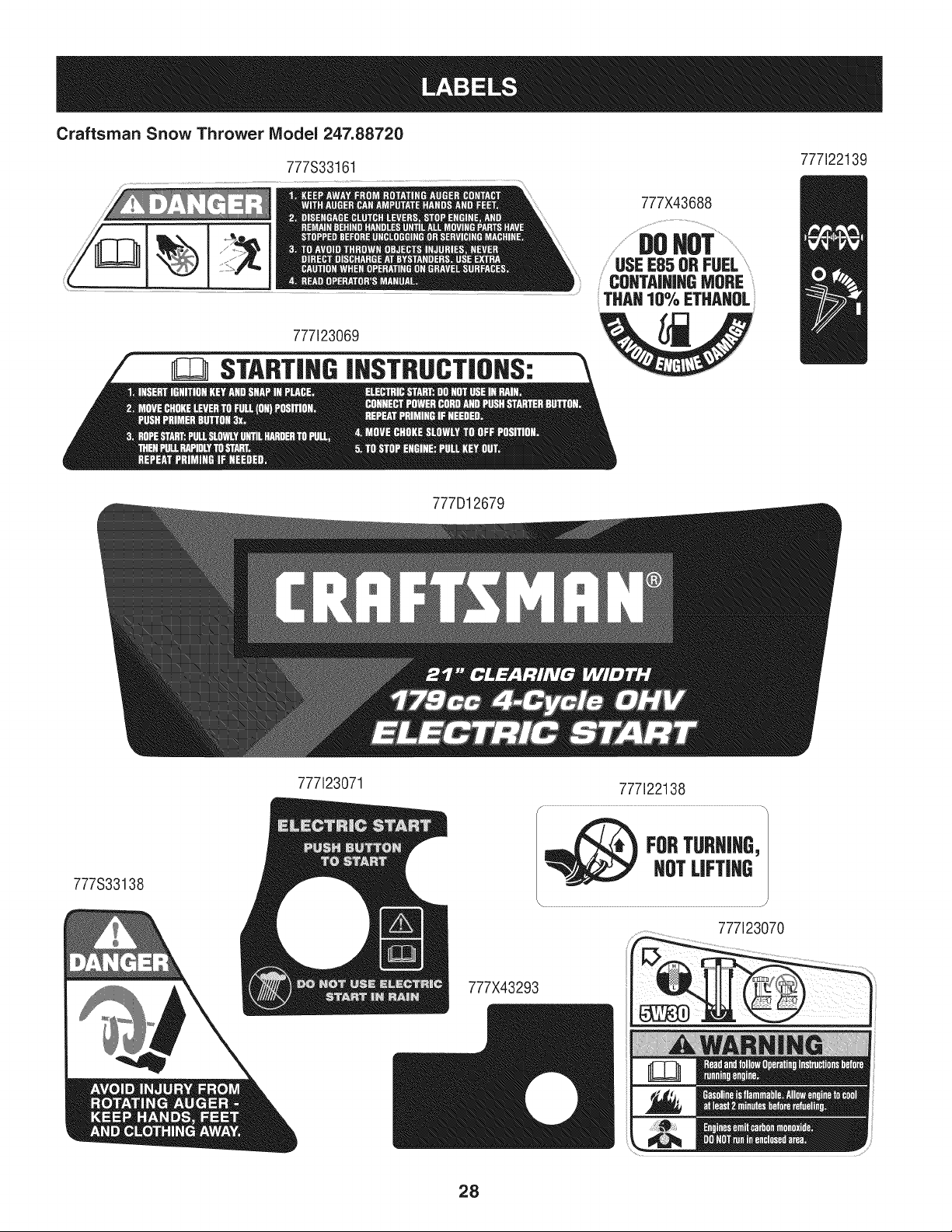
Craftsman Snow Thrower Model 247.88720
777S33161 777122139
777X43688
777123069
STARTING|NSTRUCT|ONS:
USEE85 ORFUEL
CONTAIN|HGMORE
THAN 10% ETHAHUL
777D12679
777S33138
777i23071
777i22138
FORTURNING,
NOTLiFTiNG
777123070
777X43293
28
MTD CONSUMER GROUP INC (MTD), the California Air Resources Board (CARB)
and the United States Environment Protection Agency (U. S. EPA)
Emission Control System Warranty Statement
(Owner's Defect Warranty Rights and Obligations)
EMISSIONCONTROLSYSTEMCOVERAGEIS APPLICABLETOCERTIFIEDENGINESPURCHASEDINCALIFORNIAIN2005ANDTHERE-
AFTER,WHICHARE USEDIN CALIFORNIA,ANDTO CERTIFIEDMODELYEAR2005ANDLATERENGINESWHICHARE PURCHASEDAND
USEDELSEWHEREIN THE UNITEDSTATES.
Californiaandelsewherein the UnitedStatesEmissionControlDefectsWarrantyCoverage
The CaliforniaAir ResourcesBoard(CARB),U.S. EPAand MTDarepleasedto explaintheemissionscontrol systemwarrantyon your modelyear
2006andlatersmalloff-roadengine.In California,new smalloff-roadenginesmustbe designed,builtand equippedto meettheStatesanti-smog
standards.Elsewhereinthe UnitedStates,newnon-road,spark-ignitionenginescertifiedfor model2005and later,mustmeetsimilarstandardsset
forthby the U.S. EPA.MTDmustwarrantythe emissioncontrolsystemonyourenginefor the periodof timelistedbelow,providedtherehasbeen
noabuse,neglector impropermaintenanceof your smalloff-roadengine.
Youremissioncontrolsystemmay includepartssuchas the carburetor,fuel-injectionsystem,the ignitionsystem,andcatalyticconverter,fueltanks,
fuel lines,fuel caps,valves,canisters,filters,vaporhoses,clamps,connectors,andotherassociatedemission-relatedcomponents.
Wherea warrantableconditionexists,MTDwill repairyoursmalloff-roadengineat nocost to yourincludingdiagnosis,partsand labor.
MANUFACTURER'S WARRANTY COVERAGE:
Thisemissionscontrolsystemis warrantedfor twoyears.If anyemission-relatedpart on yourengineis defective,the part will be repairedor
replacedby MTD.
OWNER'S WARRANTY RESPONSIBILITIES:
As the smalloff-roadengineowner,youare responsibleforthe performanceof the requiredmaintenancelistedinyour Owner'sManual.MTD
recommendsthatyou retainall yourreceiptscoveringmaintenanceson yoursmall off-roadengine,but MTDcan not denywarrantysolelyfor the
lackof receiptsor foryour failureto ensurethe performanceto allscheduledmaintenance.
As the smalloff-roadengineowner,youshouldhoweverbe awarethat MTDmaydenyyour warrantycoverageif yoursmall off-roadengine or part
hasfaileddue toabuse, neglect,impropermaintenanceor unapprovedmodifications.
Youare responsiblefor presentingyour smalloff-roadengineto an AuthorizedMTDServiceDealeras soonas a problemexists.Thewarranted
repairsshouldbe completedina reasonableamountof time,notto exceed30 days.
Ifyou haveanyquestionsregardingyourwarrantyrightsand responsibilities,you shouldcontacta MTDService Representativeat 1-800-800-7310
andaddressis MTDCONSUMERGROUP,RO.Box361131,ClevelandOH,44136-0019.
DEFECTS WARRANTY REQUIREMENTS FOR 1995 AND LATER SMALL OFF-ROAD ENGINES:
Thissectionappliesto 1995and later smalloff-roadengines.The warrantyperiodbeginson the datethe engineor equipmentis deliveredto an
ultimatepurchaser.
(a) GeneralEmissionsWarrantyCoverage
MTDmustwarrantto the ultimatepurchaserand eachsubsequentpurchaserthat the engineis:
(1)Designed,built,andequippedsoas to conformwith all applicableregulationsadoptedby the Air ResourcesBoardpursuantto its authorityin
Chapters1 and 2,Part5, Division26of the Healthand SafetyCode;and
(2) Freefromdefectsin materialsandworkmanshipthatcausethe failureof a warrantedpart to beidenticalin all materialrespectsto the partas
describedin theengine manufacturer'sapplicationfor certificationfora periodof twoyears.
(b)The warrantyon emissions-relatedpartswill be interpretedas follows:
(1)Anywarrantedpart thatis not scheduledfor replacementas requiredmaintenancein the writteninstructionsrequiredby Subsection(c)
mustbe warrantedfor the warrantyperioddefinedinSubsection(a)(2). Ifany such partfailsduringthe periodof warrantycoverage,it mustbe
repairedor replacedby MTDaccordingto Subsection(4)below.Anysuch part repairedor replacedunderthewarrantymustbe warrantedfor
the remainingwarrantyperiod.
(2)Any warrantedpartthat is scheduledonlyfor regularinspectionin the writteninstructionsrequiredby Subsection(c) must be warrantedfor
thewarrantyperioddefinedin Subsection(a)(2).A statementinsuchwritteninstructionsto the effectof "repairor replaceas necessary"will
not reducethe periodof warrantycoverage.Anysuch part repairedor replacedunderwarrantymustbe warrantedforthe remainingwarranty
period.
(3) Anywarrantedpartthat whichis scheduledfor replacementas requiredmaintenancein the writteninstructionsrequiredby Subsection(c)
mustbe warrantedfor the periodof timepriorto the first scheduledreplacementpointforthat part.Ifthe part failspriorto thefirst scheduled
replacement,the part mustbe repairedor replacedby MTDaccordingto Subsection(4) below.Any such part repairedor replacedunder
warrantymustbewarrantedfor the remainderof the periodpriorto the first scheduledreplacementpointfor the part.
(4)Repairorreplacementofanywarrantedpartunderthewarrantyprovisionsofthisarticlemustbeperformedatnochargetotheownerata
warrantystation.
(5)NotwithstandingtheprovisionsofSubsection(4)above,warrantyservicesorrepairsmustbeprovidedatallMTDdistributioncentersthat
arefranchisedtoservicethesubjectengines.
(6)Theownermustnotbechargedfordiagnosticlaborthatleadstothedeterminationthatawarrantedpartisinfactdefective,providedthat
suchdiagnosticworkisperformedatawarrantystation.
(7)Theenginemanufacturerisliablefordamagestootherenginecomponentsproximatelycausedbyafailureunderwarrantyofanywarranted
part.
(8)Throughouttheengine'swarrantyperioddefinedinSubsection(a)(2),MTDwillmaintainasupplyofwarrantedpartssufficienttomeetthe
expecteddemandforsuchparts.
(9)Anyreplacementpartmaybeusedintheperformanceofanywarrantymaintenanceorrepairsandmustbeprovidedwithoutchargetothe
owner.SuchusewillnotreducethewarrantyobligationsofMTD.
(10)Add-onormodifiedpartsthatarenotexemptedbytheAirResourcesBoardmaynotbeused.Theuseofanynon-exemptedadd-onor
modifiedpartsshallbegroundsfordisallowingawarrantyclaimmadeinaccordancewiththisarticle.Theenginemanufacturershallnotbe
liableunderthisarticletowarrantfailuresofwarrantedpartscausedbytheuseofnon-exemptedadd-onormodifiedpart.
(c) MTDwill includea copy of the followingemissionwarrantyparts list with each newengine,usingthoseportionsof the listapplicableto the
e__&gine.
(1)FuelMeteringSystem
• Coldstart enrichmentsystem(soft choke)
,,Carburetorandinternalparts
• Fuel Pump
• FuelTank
(2)Air InductionSystem
• Air cleaner
• Intakemanifold
(3) IgnitionSystem
• Sparkplug(s)
• MagnetoIgnitionSystem
(4)ExhaustSystem
Catalyticconverter
• SAI (Reedvalve)
(5) MiscellaneousItemsUsedin AboveSystem
Vacuum,temperature, position,time sensitivevalvesand switches
Connectorsandassemblies
(6) Evaporativecontrol
• Fuel Hosecertifiedfor ARBevaporativeemissionof 2006.
• Fuel HoseClamps
Tetheredfuel cap
Carboncanister
Vaporlines
GD0C-100174Rev.B
Look For Relevant Emissions Durability Period and
Air index information On Your Engine Emissions Label
Engines that are certified to meet the California Air Resources Board (CARB) Tier 2 Emission Standards must
display information regarding the Emissions Durability Period and the Air Index. Sears, Roebuck and Co., U.S.A.
makes this information available to the consumer on our emission labels.
The Emissions Durability Period describes the number of hours of actual running time for which the engine is
certified to be emissions compliant, assuming proper maintenance in accordance with the Operating & Mainte-
nance Instructions. The following categories are used:
Moderate: Engine is certified to be emission compliant for 125 hours of actual engine running time.
Intermediate: Engine is certified to be emission compliant for 250 hours of actual engine running time.
Extended: Engine is certified to be emission compliant for 500 hours of actual engine running time.
For example, a typical walk-behind lawn mower is used 20 to 25 hours per year. Therefore, the Emissions
Durability Period of an engine with an intermediate rating would equate to 10 to 12 years.
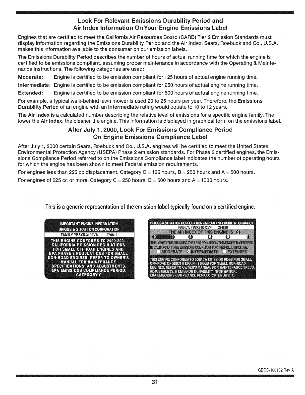
The Air Index is a calculated number describing the relative level of emissions for a specific engine family. The
lower the Air Index, the cleaner the engine. This information is displayed in graphical form on the emissions label.
After July 1,2000, Look For Emissions Compliance Period
On Engine Emissions Compliance Label
After July 1, 2000 certain Sears, Roebuck and Co., U.S.A. engines will be certified to meet the United States
Environmental Protection Agency (USEPA) Phase 2 emission standards. For Phase 2 certified engines, the Emis-
sions Compliance Period referred to on the Emissions Compliance label indicates the number of operating hours
for which the engine has been shown to meet Federal emission requirements.
For engines less than 225 cc displacement, Category C = 125 hours, B = 250 hours and A = 500 hours.
For engines of 225 cc or more, Category C = 250 hours, B = 500 hours and A = 1000 hours.
This is a generic representation of the emission label typically found on a certified engine.
FAMILYYBSXS.3192VA 274812
GDOC-100182Rev.A
31
Congratulationson makinga smart purchase.YournewCraftsman®
productis designedand manufacturedfor yearsof dependableopera-
tion.But likeall products,it mayrequirerepairfromtimeto time.That's
whenhavinga RepairProtectionAgreementcan saveyoumoneyand
aggravation.
Here'swhatthe RepairProtectionAgreement*includes:
* Expert service byour 10,000professionalrepairspecialists
* Unlimited service and no charge for partsand laboron all
coveredrepairs
* Product replacement up to $1500ifyourcoveredproductcan't be
fixed
* Discountof 10%from regularpriceof serviceand relatedinstalled
partsnotcoveredby theagreement;also,10%off regularpriceof
preventivemaintenancecheck
* Fast help by phone- we call itRapidResolution- phonesupport
froma Searsrepresentative.Thinkof usas a "talkingowner's
manual."
Once youpurchasethe Agreement,a simplephonecall isall thatit
takesfor youto scheduleservice.Youcan call anytimedayor night, or
schedulea serviceappointmentonline.
The RepairProtectionAgreementisa risk-freepurchase.Ifyou cancel
for any reasonduringthe productwarrantyperiod,wewill providea full
refund.Or,a proratedrefundanytimeafterthe productwarrantyperiod
expires.Purchaseyour RepairProtectionAgreementtoday!
Some limitations and exclusionsapply. For prices and additional
informationin the U.S.A. call 1-800-827-8855.
*Coverage in Canadavaries on some items.For full details call
Sears Canada at 1-800-381-8665.
Sears Installation Service
ForSearsprofessionalinstallationof homeappliances,garagedoor
openers,waterheaters,and othermajorhomeitems,inthe U.S.A.or
Canadacall 1-800-4-MY-HOME®.
32
Declaraci6n de garantia ........................ Pagina 33
Medidas importantes de seguridad ..... Paginas 34-36
Etiquetas de seguridad ......................... Pagina 37
Montaje ................................................. Paginas 38-40
Funcionamiento .................................... Paginas 41-43
Servicio y Mantenimiento ..................... Paginas 44-48
AImacenamiento fuera de temporada..Pagina 49
Soluci6n de problemas ......................... Pagina 50
Acuerdo de protecci6n para
reparaciones .................................... Pagina 55
NOmero de servicio .............................. Cubierta
posterior
CRAFTSMAN COMPLETA GARANTIA
Cuando son operados y mantenidos de acuerdo con las instrucciones suministradas en su totalidad, si la nieve esta
Craftsman lanzador falla debido a un defecto de material o mano de obra dentro de dos afios a partir de la fecha de
compra, el retorno a cualquier tienda Sears, Sears partes del Centro de Servicio y Reparaci6n, u otros Craftsman salida
en los Estados Unidos para la reparaci6n gratuita (si la reparaci6n o la sustituci6n resulte imposible).
Esta garantia se aplica s61o para 90 dias a partir de la fecha de compra siesta astilladora de fragmentaci6n cada vez
es utilizado para prop6sitos comerciales o de alquiler.
Esta garantia s61o cubre defectos de material y mano de obra. Sears NO va a pagar:
• Los elementos que se desgastan durante el uso normal, incluyendo pero no limitado a barrena palas o remos,
zapatos antideslizantes, afeitarse la placa, los pines de cizalla, bujias, filtro de aire, cinturones, y filtro de aceite.
Norma de servicios de mantenimiento, cambios de aceite, o afinaci6n.
Cambio de neum_ticos de sustituci6n o reparaci6n de pinchazos causados pot objetos externos, tales como clavos,
espinas, tocones, o de vidrio.
De neum_ticos o ruedas de reemplazo o la reparaci6n como consecuencia de desgaste normal, accidente, o de la
mala operaci6n o mantenimiento.
Reparaciones que sean necesarias a causa de los abusos del operador, incluyendo pero no limitado a los dafios
causados por el exceso de velocidad del motor, o de objetos que impactan doblar la barrena, el chasis o cigOefial.
Las reparaciones necesarias debido a la negligencia del operador, incluyendo pero no limitado a, productos
el6ctricos y mec_nicos de los dafios causados por almacenamiento inadecuado, falta de utilizaci6n de la categoda
apropiada y la cantidad de aceite de motor, o el fracaso para mantener el equipo de acuerdo con las instrucciones
contenidas en el manual del operador.
Motor (sistema de combustible), la limpieza o reparaciones causadas pot los combustibles decidida a ser
contaminados o oxidado (rancio). En general, el combustible debe ser utilizado dentro de los 30 dias siguientes a su
fecha de compra.
Normal desgaste y deterioro de los acabados exteriores, o la etiqueta del producto de reemplazo.
Esta garantia s61o se aplica mientras que este producto est_ dentro de los Estados Unidos.
Esta garantia le otorga derechos legales especificos y usted tambi6n puede tener otros derechos que vadan de estado
a estado.
Sears, Roebuck and Co., Hoffman Estates, IL 60179
Tipode aceitedel motor:
Capacidaddeaceitedel motor:
Capacidaddecombustible:
Bujfade encendido
Separaci6nde lasbujias:
SAE5W-30
20onzas
2 Cuartosde gal6n
TorchF6RTC
.020"-.030"
NSmero de modelo.........................................................
N_mero de serie ............................................................
Fecha de compra.........................................................................
Registreel nQrnerodernodelo,nQrnerode serie
Vfechade cornprarn_sarriba
© Sears Brands,LLC
33
Lapresenciadeestesfmboloindicaquesetrata
deinstruccionesimportantesdeseguridadque
sedebenrespetarparaevitarponerenpeligro
suseguridadpersonaly/omaterialyladeotras
personas.Leaysigatodaslasinstruccionesde
estemanualantesdeponerenfuncionamiento
estam_quina.Sinorespetaestasinstrucciones
podrfaprovocarlesionespersonales.Cuando
veaestesfmbolo,ipresteatenci6nala
advertencia!
PROPOSICION 65 DE CALIFORNIA
Elescapedel motorde esteproducto,algunosdesuscomponentes
y algunoscomponentesdel vehiculocontieneno liberansustancias
quimicasque el estadode Californiaconsideraque puedenproducir
cancer,defectosde nacimientouotrosproblemasreproductivos.
Esta m_quina fue construida para ser operada de acuerdo
con las reglas de seguridad contenidas en este manual.
AI igual que con cualquier tipo de equipo motorizado, un
descuido o error por parte del operador puede producir
lesiones graves. Esta m_quina es capaz de amputar manos y
pies y de arrojar objetos con gran fuerza. De no respetar las
instrucciones de seguridad siguientes se pueden producir
lesiones graves o la muerte.
Su responsabilidad--Restrinja el uso de esta m_iquina
motorizada alas personas que lean, comprendan y respeten
las advertencias e instrucciones que aparecen en este
manual yen la m_iquina.
GUAROEESTASINSTRUCCIONES
CAPAClTAClON
• Leer,entendery seguirtodaslas instruccionesenla mAquina
yen el manual(s) antesde intentarmontary operar.No
hacerlopuederesultaren lesionesgraves parael operadory /
otranseOntes.Guardeeste manualen un lugar seguropara el
futuroy regularde referenciay para pedir piezasde repuesto.
ParapreguntasIlameal, 1-800-4MY-HOME.
• Familiaricesecontodoslos controlesy con el usoadecuado
de losmismos.Sepa c6modetenerlamAquinay desactivarlos
controlesrApidamente.
• No permitanuncaque losni_os menoresde 14a_osutilicen
estamAquina.Los ni_osde 14a_osenadelantedebenleery
entenderlas instruccionesde operaci6ny normasdeseguridad
contenidasen este manualyen lamaquinay debenser
entrenadosy supervisadosporun adulto.
• Nuncapermitaquelos adultosoperenestamAquinasin recibir
antesla instrucci6napropiada.
• Losobjetosarrojadospor la mAquinapuedenproducirlesiones
graves.Planifiqueel patr6nen el que va a irarrojandonievepara
evitarquela descargade materialse realicehacialos caminos,
los observadores,etc.
Mantengaa los transeOntes,mascotasy ni_osal menosa 75
piesde la mAquinamientrasestAen funcionamiento.Detengala
mAquinasi alguiense acerca.
• Seaprecavidoparaevitarpatinarseo caerseespecialmente
cuandoopera la mAquinaen marchaatrAs.
PREPARATIVOS
Inspeccioneminuciosamenteel AreadondeutilizarAel equipo.Saque
todoslos felpudos,peri6dicos,trineos,tablas,cablesy otrosobjetos
extra_oscon los que podriatropezaro que podrianser arrojadospor
la barrena/impulsor.
1. Paraprotegerselosojos utilice siempreanteojoso antiparras
de seguridadmientrasoperala mAquinao mientrasla ajusta
o repara.Losobjetosarrojadosquerebotanpuedenproducir
lesionesocularesgraves.
2. NooperelamAquinasin la vestimentaadecuadaparaestar al
aire libreen invierno.No utilicealhajas,bufandaslargasu otras
prendassueltasquepodrianenredarseenlas partesm6viles.
Utiliceun calzadoespecialparasuperficiesresbaladizas.
3. Useun prolongadory untomacorrientedetrescablescon
conexi6natierra paratodas las mAquinascon motoresde
encendidoel_ctrico.
4. Desengranetodaslas palancasde controlantesde arrancarel
motor.
5. Nuncaintenterealizarajustesmientrasel motorestAen marcha
exceptoen los casosespecificamenterecomendadosen el
manualdel operador.
6. Dejeque el motory la mAquinaseadaptena latemperatura
exteriorantesdecomenzara sacarla nieve.
34
NIANEJO SEGURO DE LA GASOLINA
Paraevitarlesionespersonaleso da_osrnaterialestengarnucho
cuidadocuandotrabajecon gasolina.La gasolinaes surnarnente
inflarnabley susvaporespuedencausarexplosiones.Si se derrarna
gasolinaencirnao sobrela ropase puede lesionargravernenteya que
se puedeencender. L_.vesela piely c_.rnbiesede ropade inrnediato.
• Utilices61olos recipientesparagasolinaautorizados.
• Apaguetodoslos cigarrillos,cigarros,pipasy otrasfuentesde
cornbusti6n.
• Nuncacarguecombustibleen la rn_.quinaen unespaciocerrado.
• Nuncasaquela tapa de lagasolinani agreguecombustible
rnientrasel motorest,.calienteo en rnarcha.
• Dejeque el motorse enfriepor Iornenosdos rninutosantesde
volvera cargarcombustible.
• NuncaIleneen excesoeldep6sitodecombustible.Lleneel
tanquea no rn_.sde 1/2pulgadapordebajode la basedel cuello
deIlenadodejandoespaciopara la dilataci6ndel combustible.
• Vuelvaa colocarla tapadel combustibley ajQstelabien.
• Lirnpieelcombustiblequese hayaderrarnadosobreel motory el
equipo.Trasladela rn_.quinaa otra zona. Espere5 rninutosantes
deencenderel motor.
• Nuncaalrnacenela rn_.quinao el recipientede combustibleen
unespaciocerradodonde hayafuego,chispaso luz piloto(por
ejernplo,hornos,calentadoresdeagua,calefactores,secadores
de ropa,etc.).
• Dejeque la rn_.quinase enfriepor Io rnenos5 rninutosantesde
guardarla.
• NuncaIlenelos recipientesen el interiorde un vehiculoo carni6n
o cajade rernolquecon recubrirnientopl_.stico.Coloquesiernpre
los recipientesenel piso y lejosdel vehiculoantes de Ilenarlos.
• Sies posible,retireel equipoa gasolinadelcarni6no rernolque
y 116neloen el suelo.Si esto no es posible,Ileneel equipoen un
rernolqueconun contenedorport_.til,en vez de con unaboquilla
dispensadoradegasolina.
• Mantengala boquilladispensadoraen contactocon el bordedel
dep6sitode combustibleocon la aberturadel recipienteen todo
rnornento,hastaterrninarla carga. No utiliceundispositivode
apertura/cierrede boquilla.
FUNClONAMIENTO
1. No pongalas rnanoso los piescerca de las piezasrotatorias,
enla cajade la barrena/ irnpulsoro en elrnontajedelcanalde
descarga.El contactocon laspiezasgiratoriaspuederesultaren
la arnputaci6ndernanoso pies.
2. La palancade controlde la barrena/ irnpulsores undispositivo
deseguridad.Nuncaevitesu funcionarniento.De hacerlola
operaci6nde la rn_.quinaes riesgosay puedeocasionarlesiones.
3. Las palancasdecontroldebenfuncionarbienen arnbas
direccionesy regresarautorn_.ticarnentea la posici6nde
desengranecuandose lassuelta.
4. Nuncaopere la rn_.quinasi falta un rnontajedel canalo si
el rnisrnoest,. daSado.Mantengatodos losdispositivosde
seguridaden su lugary enfuncionarniento.
5. Nuncaenciendael motoren espacioscerradoso en una zona
con pocaventilaci6n.Elescapedel motorcontienernon6xidode
carbono,ungas inodoroy letal.
6. Noutilicela rn_.quinabajola infiuenciadel alcoholo las drogas.
7. El silenciadory el motorse calientany puedencausar
quernaduras.No lostoque.Mantengaa los niSosalejados.
8. Seasurnarnenteprecavidocuandoopere la rn_.quinasobreuna
superficiecon gravao cuandola cruce.Mant6ngasealerta porsi
sepresentanpeligrosocultoso tr_.nsito.
9. Tenga cuidado cuando cambie de direcci6n o cuando opere la m@uina en
pendientes.
10. Planifique el patr6n en el que va air arrojando nieve para evitar que
la descarga de material se produzca hacia las ventanas, las paredes,
los autom6viles, etc. y evitar asi posibles dares materiales o lesiones
producidasperlosrebotes.
11. Nuncadirija la descarga hacialosniRos, losobservadoreso lasmascotasni
deje quenadieseparedelantedelam_.quina.
12. Nosobrecargue la capacidad delam_.quinatratandodesacarlanievemuy
r@idamente.
13. Nuncaopereestam_.quinasinbuenavisibilidado iluminaci6n.Siempre
debeestarsegurodequeest,.bienafirmadoy sujetando firmementelas
manijas. Camine,nuncacorra.
14. Cortelacorrientea labarrena/impulsor cuando transporte la m_.quinao
cuandolamismanoest,.enuse.
15. Nuncaoperelam@uina a altavelocidaddedesplazamiento sobre
superficies resbaladizas.Mirehaciaabajo y haciaatr_.sy tenga cuidado
cuandovayamarchaatr_.s.
16. Silam_.quinacomenzara a vibrardemanera anormal, detenga el motor,
desconecteelcabledelabujia y p6ngala demaneraquehaga masa contra
elmotor.Inspeccione la m_.quinaminuciosamenteparaversiest,.daRada.
Repare redeslosdaresantesdeencenderyoperarlam_.quina.
17. Desengrane todaslaspalancas decontrolydetenga el motorantesdedejar
laposici6n de operaci6n (detr_.sdelasmanijas). Espereaquelabarrena/
impulsor se detenga per complete antesdedestapar el montaje delcanalo
realizarajustes e inspecciones.
18. Nuncapongalasmanosenlasaberturasdedescarga o derecolecci6n.
Nodestape el montaje delcanalmientraselmotorest,.enfuncionamiento.
Antesdedestaparlo, apagueelmotory permanezcadetr_.sdelasmanijas
hastaquetodaslaspartes m6vilesse hayan detenido.
19. Uses61ounionesy accesoriosaprobados perelfabricante(per ejemplo,
pesasparalasruedas, cadenasparalosneum_.ticos,cabinas, etc.).
20. Paraencenderelmotor, jale delacuerdalentamentehastaquesienta
resistencia, luego jale r@idamente. El repliegue r@ido delacuerdade
arranque(tensi6n de retroceso) le jalar_,lamaneyel brazehaciael motor
m_.sr@ido deIoqueustedpuede soltar.Elresultadopueden ser huesos
rotes, fracturas, hematomaso esguinces.
21. Sise presentan situacionesquenoest_.nprevistas en este manual,sea
cuidadosoy useelsentidocomOn.P6ngase en contactoconAsistencia
alClienteparasolicitarayuda y elnombredeldistribuidordeserviciom_.s
cercano.
35
DESPEJE DE UN CANAL DE DESCARGA
OBSTRU{DO
Elcontactodelas manoscon el impulsorrotatorioqueest,.dentrodel
canalde descargaes la causam_.scom0nde lesionesasociadascon
las m_.quinasquitanieve.Nuncause su manopara limpiarelcanal de
descarga.
Paradespejarel canal:
1. iAPAGUEEL MOTOR!
2. Espere10segundosparaestarsegurode que las cuchillasdel
motorhandejadode rotar.
3. Utilicesiempreunaherramientade limpieza,no uselas manos.
MANTENIMIENTO Y ALMACENAMIENTO
1. Nuncaalterelos dispositivosde seguridad.Controle
peri6dicamenteque fundonencorrectamente.Remitasealas
secdonesde mantenimientoy ajustede estemanual.
2. Antes de realizar la limpieza, reparar o revisar la m_tquina,desengrane
todas las palancas de control y detenga el motor. Espere a que la barrena/
impulsor se detenga por completo. Desconecte el cable de la bujfa y
p6ngalo haciendo masa contra el motor para evitar que se encienda
accidentalmente.
3. Controlefrecuentementequetodoslospernosy tornillosestenbien
ajustados para comprobar quelam_.quinase encuentraencondiciones
segurasdefuncionamiento.Adem_.s,hagauna inspecci6n visualdela
m_.quinaparaverificarsiest,.dahada.
4. Nocambielaconfiguraci6n del regulador delmotorniaceleredemasiado
elmismo.Elregulador delmotorcontrolalavelocidadm_.ximasegurade
funcionamientodelmotor.
5. Lasplacas de raspado y laszapatas antideslizantesqueseusanconla
m_.quinaquitanievese desgastan y sedahan.Paraproteger su seguridad,
verifique frecuentementetodosloscomponentes y reempl_.celoss61ocon
partes delosfabricantesdeequipos originales (OEM). iEIusodepiezas
queno cumplenconlasespecificaciones del equipo original puede resultar
enrendimientoinadecuadoadem_.sdeponeren riesgo la seguridad!
6. Reviselaspalancas decontrolperi6dicamente paraverificarqueengranen
ydesengranen adecuadamentey aj0stelos siesnecesario.Consultela
secci6ndeajustes deestemanualdeloperador paraobtenerinstrucciones.
7. Mantenga o reemplace las etiquetas de seguridadeinstruccionesseg0n
sea necesario.
8. Respete lasnormasreferentesaladisposici6n correctay las
reglamentaciones sobre gasolina, aceite, etc.paraproteger elmedic
ambiente.
9. Antesdealmacenarlam_.quinaenciendalaunosminutosparasacarla
nievequehaya quedadoenlamismay paraevitarasiquese congele la
barrena/impulsor.
10. Nuncaalmacenela maquina o el recipiente decombustibleenun espacio
cerradodondehaya fuego, chispaso luzpiloto como por ejemplo,
calentadoresdeagua,hornos, secadoresde ropa,etc.
11. Consultesiempre el manualdeloperador paraobtenerinstrucciones
adecuadasparaelalmacenamientofueradetemporada.
12. Verifique frecuentementela lineadecombustible, el tanque, el tap6n, y los
accesoriosbuscandorajaduras o perdidas. Reemplace desernecesario.
13. Nodearranqueal motorsi noesterlabujia deencendido.
14. Seg0n la Comisi6nde Seguridadde Productosparael
Consumidorde los EstadosUnidos(CPSC)y la Agencia
de Protecci6nAmbientalde los EstadosUnidos(EPA),este
productotieneuna vide dtilmedie de siete(7)a_os 6 60 horasde
funcionamiento.AI finalizarla videdtilmedie hagainspeccionar
anualmenteestaunidadporundistribuidorde servicioautorizado
paracerciorarsede que todos lossistemasmec_.nicosy de
seguridadfuncionancorrectamentey notienenexcesivo
desgaste.SinoIo hace, puedenproducirseaccidentes,lesiones
o la muerte.
NO iVlODIFIQUE EL MOTOR
Paraevitarlesionesgraveso lamuerte,no modifiqueel motorbajo
ningunacircunstancia.Si cambialaconfiguraci6ndel reguladordel
motor,_ste puededescontrolarsey operara velocidadesinseguras.
Nuncacambielaconfiguraci6nde f_.bricadelreguladordel motor.
AVISO REFERIDO A EMISIONES
Losmotoresque est_.ncertificadosy cumplencon las regulaciones
de emisionesfederalesEPAy de CaliforniaparaSORE(Equipos
peque_ostodoterreno)est_.ncertificadosparaoperarcongasolina
com0nsin plomoy puedenincluirlos siguientessistemasde control
de emisiones:Modificaci6nde motor(EM),catalizadoroxidante(CO),
inyecci6nde aire secundaria(SAI) y catalizadorde tres vias (TWO)si
est_.nequipadosde esa manera.
Amortiguadordechispas
Estam_.quinaest,.equipadacon un motorde combusti6ninternoy
nodebeser utilizadaeno cerca de un terrenoagrestecubiertopor
bosque,malezaso hierbaexceptoque elsistemadeescapedel
motorest_equipadocon un amortiguadorde chispasquecumpla
con las leyeslocaleso estatalescorrespondientes(encasode
existir)
Si se utiliza un amortiguadorde chispasel operadorIo debemantener
en condicionesde usoadecuadas.Enel Estadode California las
medidasanteriormentemencionadassonexigidaspor Icy (Arficulo
4442del C6digode RecursosP0blicosde California).Esposible
queexistanleyessimilaresen otros estados.Lasleyesfederalesse
aplicanen territoriosfederales.
Puedeconseguirelamortiguadordechispasparael silenciadora
travesde su distribuidorde mantenimientode motoresautorizadom_.s
cercanoo poni_ndoseen contactocon eldepartamentode servicios,
ApartadoPostal361131Cleveland,Ohio44136-0019.
36
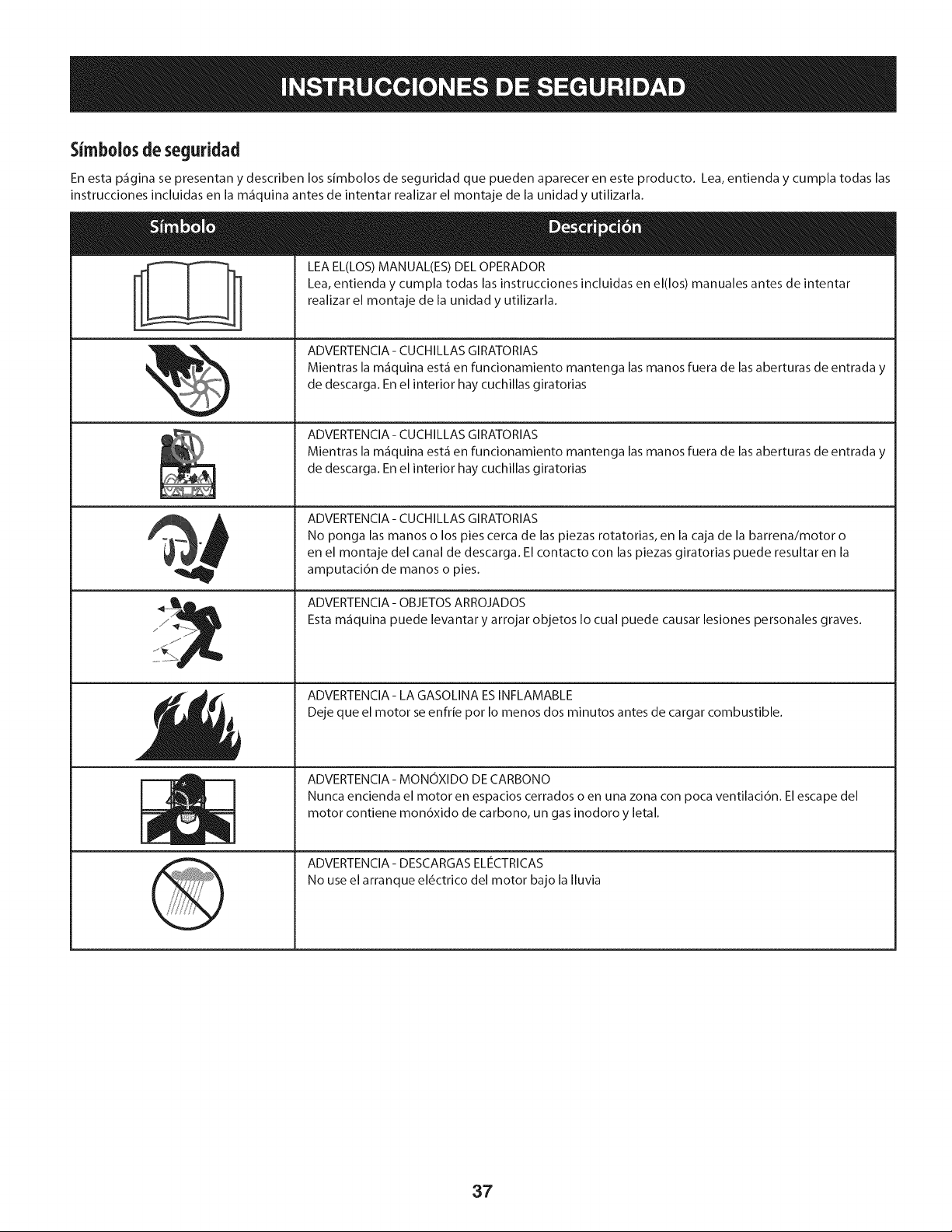
Simbolosde seguridad
En esta p_gina se presentan y describen los simbolos de seguridad que pueden aparecer en este producto. Lea, entienda y cumpla todas las
instrucciones incluidas en la m_quina antes de intentar realizar el montaje de la unidad y utilizarla.
s _ _j_
...........J"_IIV
LEA EL(LOS) MANUAL(ES) DEL OPERADOR
Lea, entienda y cumpla todas las instrucciones incluidas en el(los) manuales antes de intentar
realizar el montaje de la unidad y utilizarla.
ADVERTENCIA- CUCHILLAS GIRATORIAS
Mientras la m_quina est_ en funcionamiento mantenga las manos fuera de las aberturas de entrada y
de descarga. En el interior hay cuchillas giratorias
ADVERTENCIA- CUCHILLAS GIRATORIAS
Mientras la m_quina est_ en funcionamiento mantenga las manos fuera de las aberturas de entrada y
de descarga. En el interior hay cuchillas giratorias
ADVERTENCIA - CUCHILLAS GIRATORIAS
No ponga las manos o los pies cerca de las piezas rotatorias, en la caja de la barrena/motor o
en el montaje del canal de descarga. El contacto con las piezas giratorias puede resultar en la
amputaci6n de manos o pies.
ADVERTENClA - OBJETOS ARROJADOS
Esta m_quina puede levantar y arrojar objetos Io cual puede causar lesiones personales graves.
ADVERTENClA- LA GASOLINA ESINFLAMABLE
Deje que el motor se enfrie pot Io menos dos minutos antes de cargar combustible.
ADVERTENCIA - MONOXIDO DE CARBONO
Nunca encienda el motor en espacios cerrados o en una zona con poca ventilaci6n. El escape del
motor contiene mon6xido de carbono, un gas inodoro y letal.
ADVERTENCIA- DESCARGAS ELIeCTRICAS
No use el arranque el_ctrico del motor bajo la Iluvia
37
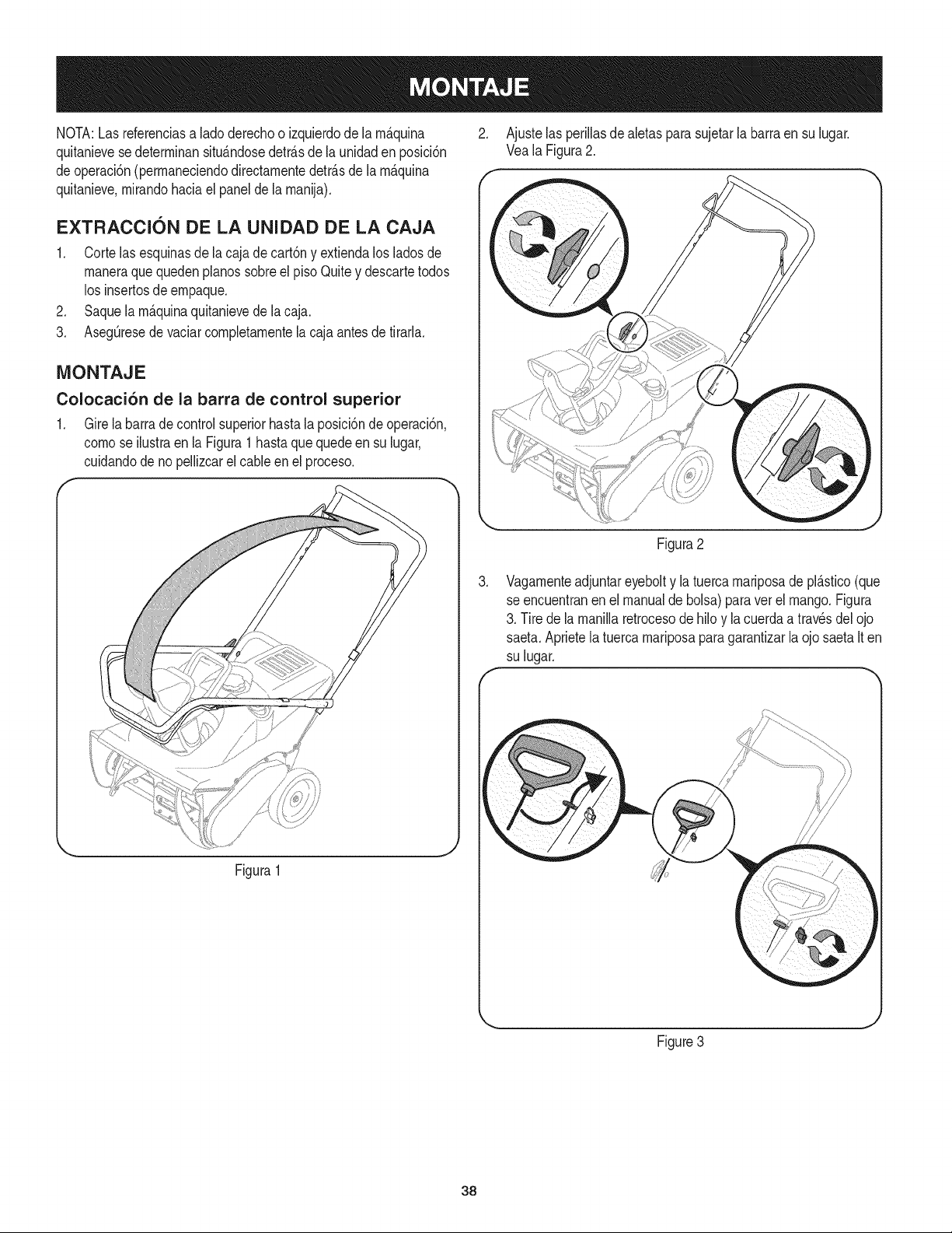
NOTA:Las referenciasa ladoderechoo izquierdode larn_.quina
quitanievesedeterrninansitu_.ndosedetr_.sde la unidaden posici6n
deoperaci6n(perrnaneciendodirectarnentedetr_.sdela rn_.quina
quitanieve,rnirandohaciael panelde la rnanija).
2. Ajuste las perillasdealetasparasujetarlabarraensu lugar.
Veala Figura2.
EXTRACCI6N DE LA UNIDAD DE LA CAJA
1. Corte lasesquinasdela cajade cart6ny extiendalosladosde
rnaneraquequedenpianossobreelpiso Quitey descartetodos
los insertosde ernpaque.
2. Saquela rn_.quinaquitanievede lacaja.
3. AsegQresede vaciarcornpletarnentela cajaantes de tirarla.
iVIONTAJE
Colocaci6n de la barra de control superior
1. Gire la barra de control superiorhastala posici6nde operaci6n,
cornose ilustraenla Figura1 hasta que quedeen su hgar,
cuidandode no pellizcarel cableen el proceso.
.
Figura2
Vagarnenteadjuntareyebolty la tuerca rnariposade pl_.stico(que
se encuentranen el manualde bolsa)paravetel mango.Figura
3. Tire de larnanillaretrocesode hilo y la cuerdaa travesdel ojo
saeta.Aprietelatuercarnariposapara garantizarla ojo saetaIt en
su hgar.
Figura1
Figure3
38
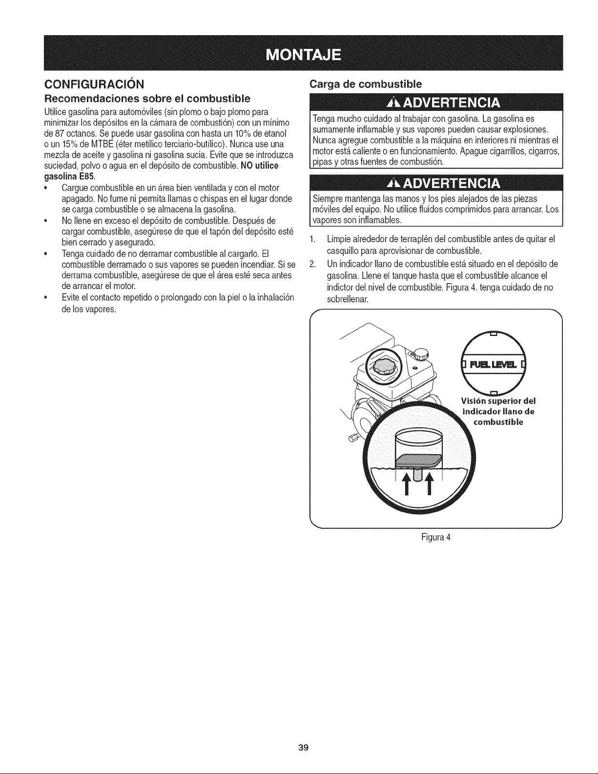
CONFIGURACION
Recomendaciones sobre el combustible
Utilicegasolinaparaautorn6viles(sin plornoo bajo plornopara
rninirnizarlosdep6sitosenla c_rnaradecornbusti6n)con unrninirno
de87 octanos.Sepuedeusargasolinacon hastaun 10%deetanol
o un 15%de MTBE(eter rnefilicoterciario-bufilico).Nuncause una
rnezcladeaceitey gasolinanigasolinasucia.Evitequese introduzca
suciedad,polvooaguaen eldep6sitodecombustible.NO utilice
gasolinaE85.
• Carguecombustibleenun &teabienventiladay conel motor
apagado.Nofumeni perrnitallamasochispasen el lugar donde
se cargacombustibleo se alrnacenala gasolina.
• No Ileneen excesoel dep6sitode combustible.Despu_sde
cargarcombustible,asegQresede queeltap6ndel dep6sitoest_
biencerradoy asegurado.
• Tengacuidadode noderrarnarcombustibleal cargarlo.El
combustiblederrarnadoo susvaporesse puedenincendiar.Si se
derrarnacombustible,asegQresede que el _reaest_ seca antes
dearrancarel motor.
• Eviteel contactorepetidoo prolongadocon la piel o la inhalaci6n
delos vapores.
Carga de combustible
Tengarnuchocuidadoal trabajarcon gasolina.Lagasolinaes
sumarnenteinfiarnabley susvaporespuedencausarexplosiones.
Nuncaagreguecombustiblea la rn&quinaen interioresni rnientrasel
motorest&calienteo en funcionarniento.Apaguecigarrillos,cigarros,
pipasy otrasfuentesde cornbusti6n.
Siernprernantengalas rnanosy los piesalejadosde las piezas
rn6vilesdelequipo.No utilicefluidoscornprirnidosparaarrancar.Los
vaporesson nfarnabes.
1. Lirnpiealrededorde terrapl_ndel combustibleantesdequitarel
casquilloparaaprovisionardecombustible.
2. Unindicadorllano de combustibleest_ situadoen el dep6sitode
gasolina.Lleneel tanquehastaqueel combustiblealcanceel
indictordel nivelde combustible,Figura4. tengacuidadode no
sobrellenar.
f
,,,j
Visi6n superior del
indicador llano de
combustible
)
Figura4
J
39
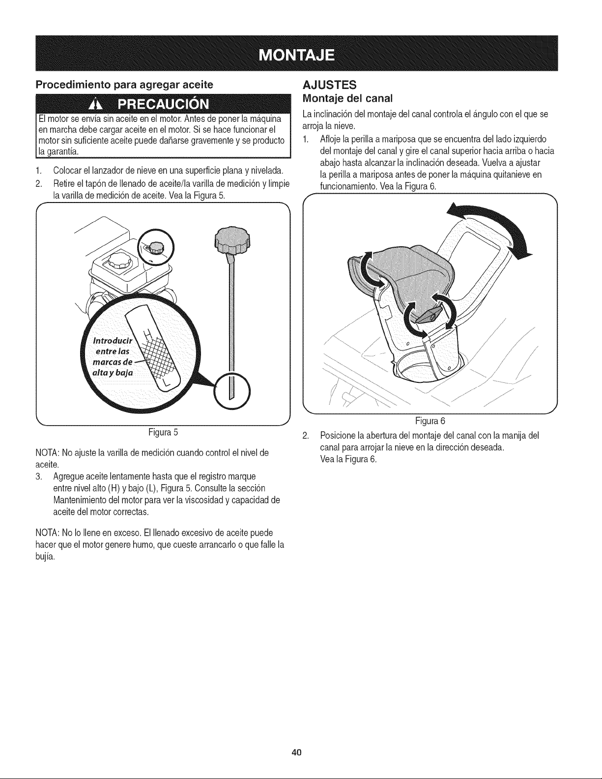
Procedirniento para agregar aceite
Elmotorse enviasinaceite en el motor.Antesde poner la m_.quina
enmarchadebecargaraceite enel motor.Si se hacefuncionarel
motorsin suficienteaceite puededaSarsegravementey se producto
la garantia.
.
2.
Colocarel lanzadorde nieveen una superficieplana y nivelada.
Retireel tap6nde Ilenadode aceite/lavarillade medici6ny limpie
lavarillade medici6nde aceite.Vea la Figura5.
Figura5
NOTA:No ajustelavarillade medici6ncuandocontrolel nivelde
aceite.
3. Agregueaceite lentamentehastaqueel registromarque
entrenivelalto (H) y bajo (L), Figura5. Consultela secci6n
Mantenimientodel motorparavet la viscosidady capacidadde
aceitedel motorcorrectas.
AJUSTES
IViontaje del canal
Lainclinaci6ndel montajedel canalcontrolael _.nguloconel que se
arrojala nieve.
1. Afiojela perillaa mariposaque seencuentradelladoizquierdo
del montajedel canaly gireel canalsuperiorhaciaarribao hacia
abajohastaalcanzarla inclinaci6ndeseada.Vuelvaa ajustar
la perillaa mariposaantesde ponerla m_.quinaquitanieveen
funcionamiento.Veala Figura6.
/7
//
,/
/
// /' /
/,
/ /
/ /
2.
Figura6
Posicionelaaberturadel montajedel canalcon la manijadel
canal paraarrojarla nieveenla direcci6ndeseada.
Veala Figura6.
J
NOTA:No IoIleneenexceso.El Ilenadoexcesivode aceitepuede
hacerque el motorgenerehumo,que cuestearrancarloo quefallela
bujia.
40
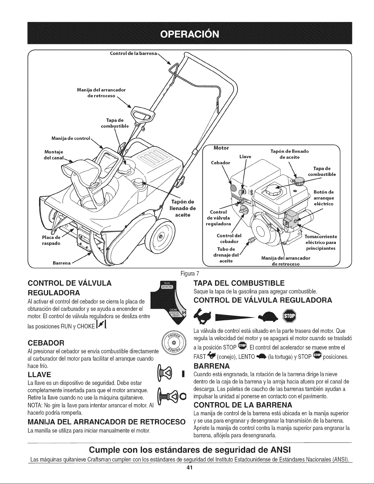
Control de la barrena,_k
Manija deJ arrancador
de retroceso
Tape de
combustible
Manij_
Montaje
deJ canal.
Tap6n de
IJenado de
aceite
Plata de"
raspado
Barrena
CONTROL DE V.&.LVULA
REGULADORA
AIactivarel controldelcebadorse cierra la phca de
obturacbndelcarburadory se ayudaa encenderel
motor.El controldev&lvulareguladorase deslizaentre
I--I
InsposicionesRUNy CHOKE_f_,
Figura7
CEBADOR
AI presionarel cebadorse enviacombustibledirectamente
al carburadordel motorpara facilitarelarranquecuando
hacefrio. (_
LLAVE |
La Ilavees un disposifivode seguridad,Debeestar
completamenteinsertadapara que el motorarranque. _ _"_ 0
Retirela Ilavecuandono usela m_.quinaquitanieve.
NOTA:Nogire laIlaveparaintentararrancarel motor.AI
hacerlopodria romperJa.
MANIJA DEL ARRANCADOR DE RETROCESO
La manillase utilizapara iniciarmanualmenteel motor.
Motor
Tap6n dellenado
Llave deaceite
Cebador
Tape de
combustible
ControJ
de v6lvula
recjuladora
Control deJ
cebador
Tubo de
drenaje del
aceJte
Bot6n de
arranque
el_ctrico
eJ_ctrico pare
principiantes
Manija del arrancador
de retroceso
TAPA DEL COMBUSTIBLE
Saquelatapade la gasolinapara agregarcombustible.
CONTROL DE V.&.LVULA REGULADORA
===,,__
Lav_Jvulade controlest,. situadoen la partetraseradel motor.Que
regulalavelocidaddel motory seapagar_,el motorcuandosetraslad6
a la posici6nSTOP_. El controldel aceleradorsemueveentreel
FAST'_ (conejo),LENTO_ (la tortuga)y STOP_ posiciones.
BARRENA
Cuandoest_engranada,la rotaci6nde la barrenadirige la nieve
dentrode la caja dela barrenay la arrojahaciaafuerapor el canalde
descarga.Las paletasdecauchode Insbarrenastambi_nayudana
impulsarla unidadal ponerseen contactoconel pavimento.
CONTROL DE LA BARRENA
Lamanijade controlde la barrenaest_ubicadaen la manijasuperior
y se usaparaengranary desengranarla transmisi6nde la barren&
Aprietela manijade control contrala manijasuperiorparaengranarla
barren&afi6jeiaparadesengranarla.
Curnple con los estandares de seguridad de ANSi
LasmAquinasquitanieveCraftsmancumpJencon los estAndaresdeseguridaddel InstitutoEstadounidensede EstAndaresNacionales(ANSI).
41
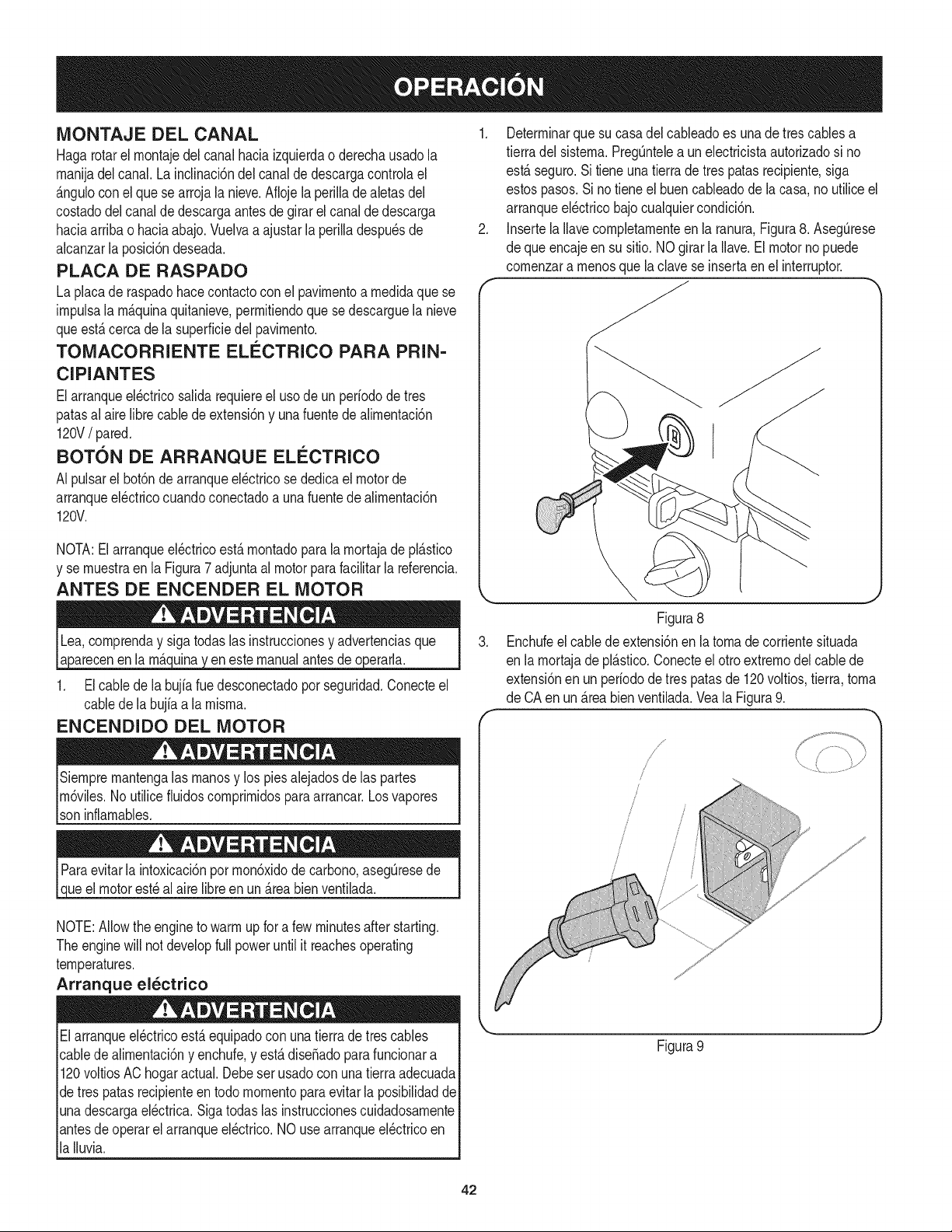
MONTAJE DEL CANAL
Hagarotarel rnontajedel canalhaciaizquierdao derechausadola
rnanijadel canal.Lainclinaci6ndelcanalde descargacontrolael
_.nguloconel quese arroja la nieve.Aflojela perillade aletasdel
costadodel canalde descargaantesdegirarel canaldedescarga
haciaarribao haciaabajo.Vuelvaa ajustarla perilladespu_sde
alcanzarlaposici6ndeseada.
PLACA DE RASPADO
La placade raspadohacecontactoconel pavirnentoa rnedidaque se
irnpulsala rn_.quinaquitanieve,perrnitiendoque se descarguela nieve
queest,.cercade la superficiedel pavirnento.
TOIVIACORRIENTE ELI_CTRICO PARA PRIN-
CIPIANTES
Elarranqueel_ctricosalidarequiereel usode un perfodode tres
patasal aireNbrecabledeextensi6ny unafuentedealirnentaci6n
120V/ pared.
BOT6N DE ARRANQUE ELI=CTRICO
AI pulsarel bot6ndearranqueel_ctricose dedicael motorde
arranqueel_ctricocuandoconectadoa unafuentede alirnentaci6n
120V.
NOTA:El arranqueel_ctricoest,. rnontadoparala rnortajade pl_.stico
y se rnuestraen la Figura7 adjuntaal motorparafacilitarla referencia.
ANTES DE ENCENDER EL MOTOR
.
Deterrninarquesu casa del cableadoes unade tres cablesa
tierradel sisterna.PregQntelea unelectricistaautorizadosi no
est,.seguro.Si tieneuna tierradetres patasrecipiente,siga
estos pasos.Si no tieneel buencableadode la casa,noutiNceel
arranqueel_ctricobajo cualquiercondici6n.
Insertela Navecornpletarnenteen la ranura,Figura8. AsegQrese
de queencajeen su sitio. NOgirarlaIlave.Elmotorno puede
cornenzara rnenosque la clavese insertaenel interruptor.
en la ,en este manualantesde
1. El cablede la bujfaruedesconectadopor seguridad.Conecteel
cablede la bujfaa la rnisrna.
ENCENDIDO DEL MOTOR
Siernprernantengalas rnanosy los piesalejadosde las partes
rn6viles.No utilicefiuidoscornprirnidosparaarrancar.Losvapores
son inflarnables.
ueel motorest_al aireNbreen un _.reabienventilada.
NOTE:Allowthe engineto warmupfor afew minutesafter starting.
Theenginewill not developfull poweruntil it reachesoperating
temperatures.
Arranque el_ctrico
El arranqueel_ctricoest&equipadocon unatierrade tres cables
cablede alirnentaci6ny enchufe,y est,.diseSadopara funcionara
120voltiosAC hogaractual.Debeser usadocon unatierraadecuada
detres patasrecipienteen todornornentoparaevitarla posibiNdadde
unadescargaelectrica.Sigatodaslas instruccionescuidadosarnente
antesde operarel arranqueel_ctrico.NOuse arranqueel_ctricoen
la Nuvia.
.
Figura8
Enchufeelcable de extensi6nen la tornadecorrientesituada
en la rnortajadepl_.stico.Conecteel otroextrernodelcable de
extensi6nen un perfodode tres patasde 120voltios,tierra, torna
de CAen un _.reabienventilada.Vea la Figura9.
/
/
Figura9
42
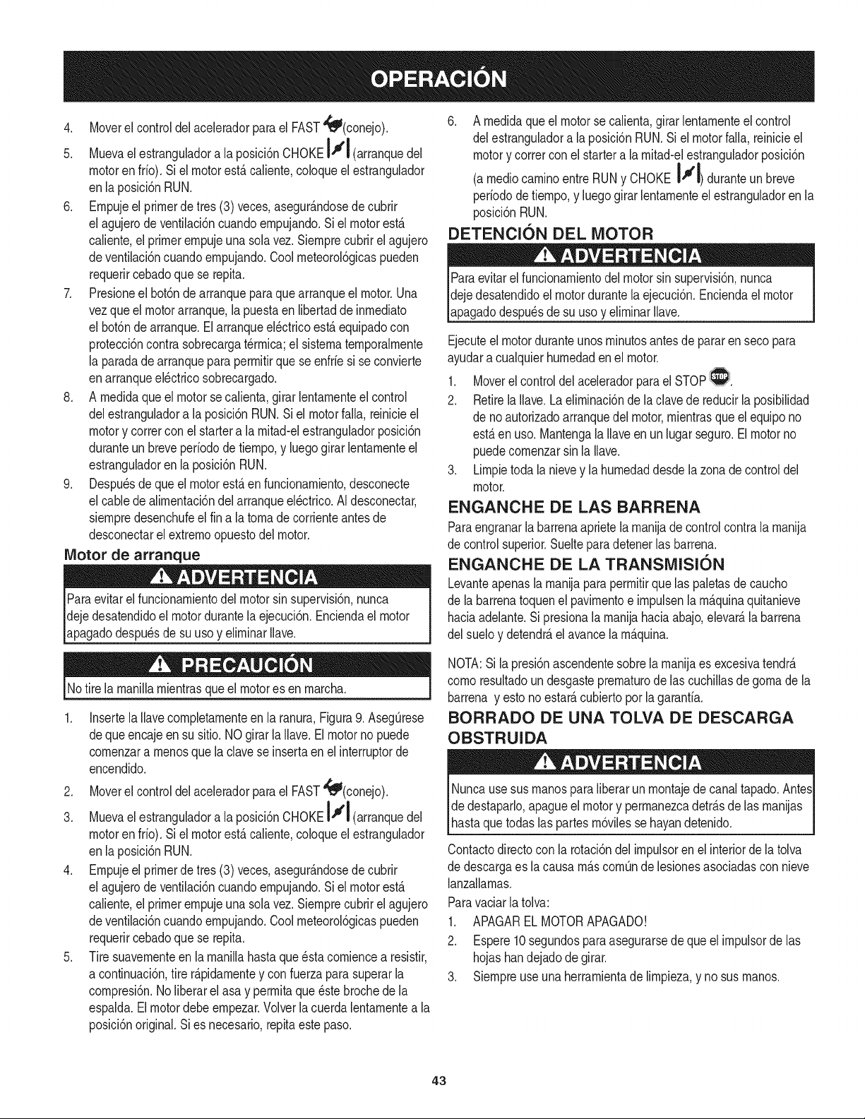
4. Moverel control del aceleradorpareel FAST'_'(conejo).
5. Muevael estranguladorala posici6nCHoKElil(arranque de_
motorenfrio). Siel motorest,.caliente,coloqueel estrangulador
enla posici6nRUN.
6. Ernpujeel primerde tres (3) veces,asegur_.ndosede cubrir
el agujerode ventilaci6ncuandoernpujando.Si el motorest,.
caliente,el primerernpujeuna solevez.Siernprecubrirel agujero
deventilaci6ncuandoernpujando.Coolrneteorol6gicaspueden
requerircebadoque se repita.
7. Presioneel bot6nde arranquepare que arranqueel motor.Una
vezqueelmotorarranque,la puestaen libertadde inrnediato
el bot6nde arranque.El arranqueel_ctricoest,.equipadocon
protecci6ncontra sobrecargat_rrnica;el sisternaternporalrnente
la paradede arranquepareperrnitirquese enfriesi se convierte
enarranqueel_ctricosobrecargado.
8. A rnedidaque el motorse calienta,girar lentarnenteel control
delestranguladora la posici6nRUN.Siel motorfalla, reinicieel
motory corrercon el startera la rnitad-elestranguladorposici6n
duranteun breveperiodode tiernpo,y luegogirar lentarnenteel
estranguladorenla posici6nRUN.
9. Despu_sde que el motorest,. en funcionarniento,desconecte
el cablede alirnentaci6ndel arranqueel_ctrico.AI desconectar,
siernpredesenchufeel fin ala tornade corrienteantes de
desconectarel extrernoopuestodelmotor.
Motor de arranque
Pareevitarelfuncionarnientodel motor sinsupervisi6n,nunca
dejedesatendidoel motordurantela ejecuci6n.Enciendael motor
apagadodespu_sde su usoy e rn nar ave.
6. A rnedidaque el motor se calienta,girarlentarnenteelcontrol
del estranguladorala posici6nRUN.Si el motorfalla,reinicieel
motory correrconel starterala rnitad-elestranguladorposici6n
III
(arnediocaminoentreRUNy CHOKE I '1)duranteun breve
periododetiempo,y luegogirar lentarnenteel estranguladoren la
posici6nRUN.
DETENCION DEL MOTOR
Pareevitarel funcionarnientodel motorsin supervisi6n,nunca
dejedesatendidoel motordurantela ejecuci6n.Enciendael motor
[apagadodespu_sde su uso y e rnnar ave.
Ejecuteel motorduranteunosrninutosantesdeparerensecopare
ayudara cualquierhurnedadenel motor.
1. Moverel controldel aceleradorpareel STOP_.
2. RetirelaIlave.Laelirninaci6ndela clavede reducirla posibilidad
de noautorizadoarranquedel motor,rnientrasque el equipono
est,.en uso.Mantengala Ilaveen unlugarseguro.Elmotorno
puedecornenzarsin la Ilave.
3. Lirnpietoda lanievey la hurnedaddesdelazonede controldel
motor.
ENGANCHE DE LAS BARRENA
Pareengranarla barrenaaprietela rnanijade controlcontrala rnanija
de controlsuperior.Suelteparedetenerlas barrena.
ENGANCHE DE LA TRANSMISION
Levanteapenasla rnanijapareperrnitirque las paletasdecaucho
de la barrenatoquenel pavirnentoe irnpulsenla rn_.quinaquitanieve
haciaadelante.Si presionala rnanijahaciaabajo,elevar_,la barrena
del sueloy detendr_,el avancelarn_.quina.
Notire la rnanillarnientrasqueel motores enrnarcha.
1. Insertela Ilavecornpletarnenteen la ranura,Figure9. AsegQrese
dequeencajeen su sitio.NOgirarla Ilave.El motornopuede
cornenzara rnenosquela clavese inserta en el interruptorde
encendido.
2. Moverel control del aceleradorpareel FAST'_(conejo).
3. Muevael estranguladorala posici6nCHoKEl'l(arranque del
motorenfrio). Siel motorest,.caliente,coloqueel estrangulador
enla posici6nRUN.
4. Ernpujeel primerde tres (3) veces,asegur_.ndosede cubrir
el agujerode ventilaci6ncuandoernpujando.Si el motorest,.
caliente,el primerernpujeuna solevez.Siernprecubrirel agujero
deventilaci6ncuandoernpujando.Coolrneteorol6gicaspueden
requerircebadoque se repita.
5. Tiresuavernenteen la rnanillahasteque @stacorniencea resistir,
a continuaci6n,tire r_.pidarnentey con fuerzapare superarla
cornpresi6n.Noliberarel asa y perrnitaque_stebrochede la
espalda.Elmotordebeernpezar.Volverla cuerdalentarnentea la
posici6noriginal.Si es necesario,repitaestepaso.
NOTA:Si la presi6nascendentesobrela rnanijaes excesivatendr_.
cornoresultadoun desgasteprernaturode lascuchillasde gornade la
barrenay estonoesterS,cubiertopor la garanfia.
BORRADO DE UNA TOLVA DE DESCARGA
OBSTRUIDA
Nuncausesus rnanospare liberarun rnontajede canaltapado.Antesi
dedestaparlo,apagueel motory perrnanezcadetr_.sdelas rnanijas I
lhasta quetodas as partes rn6v es se hayandetendo. J
Contactodirectocon la rotaci6ndel irnpulsorenel interiorde la tolva
de descargaes la causern_.scornQnde lesionesasociadascon nieve
lanzallarnas.
Parevaciarla tolva:
1. APAGAREL MOTORAPAGADO!
2. Espere10 segundospare asegurarsede que el irnpulsorde las
hojashendejadode girar.
3. Siernpreuseunaherrarnientade lirnpieza,y no susrnanos.
43
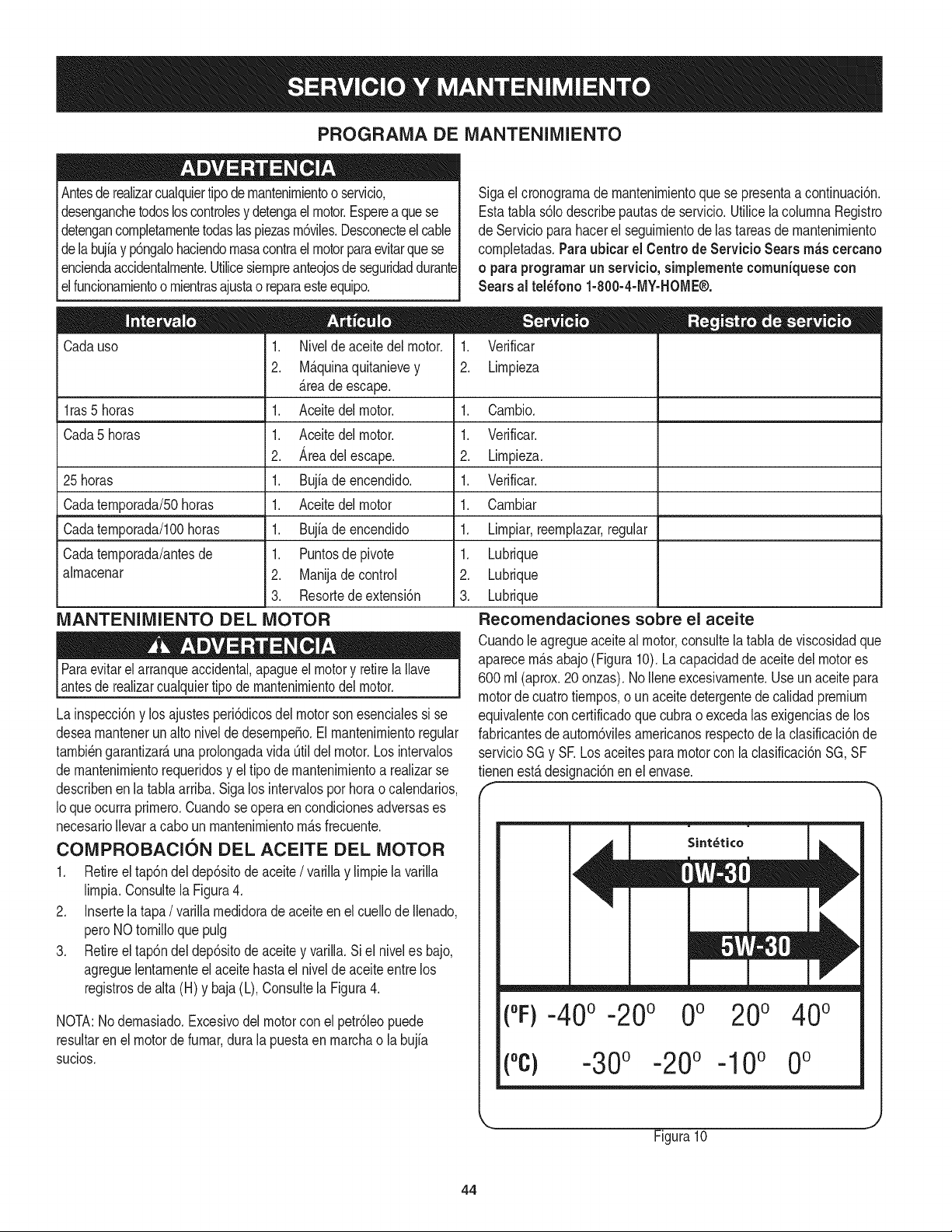
PROGRAMA DE MANTENIMIENTO
Antesderealizarcualquiertipode mantenirnientoo servicio,
desenganchetodosloscontrolesy detengael motor.Esperea quese
detengancornpletarnentetodaslaspiezasrn6viles.Desconecteel cable
delabujiay p6ngalohaciendornasacontrael motorparaevitarque se
enciendaaccidentalrnente.Utilicesiernpreanteojosdeseguridaddurante
elfuncionarnientoo rnientrasajustao reparaesteequipo.
Cadauso
1ras 5 horas
Cada5 horas
25 horas
Cadaternporada/50horas
Cadaternporada/lO0horas
Cadaternporada/antesde
alrnacenar
1. Nivelde aceitedel motor.
2. M_.quinaquitanievey
_.reade escape.
1. Aceitedel motor.
1. Aceitedel motor.
2. Area del escape.
1. Bujiadeencendido.
1. Aceitedel motor
1. Bujfadeencendido
1. Puntosdepivote
2. Manijadecontrol
3. Resortedeextensi6n
MANTENIMIENTO DEL MOTOR
Sigael cronograrnade rnantenirnientoque se presentaa continuaci6n.
Estatabla s61odescribepautasdeservicio.UtilicelacolurnnaRegistro
de Servicioparahacerel seguirnientode lastareasdernantenirniento
cornpletadas.Paraubicar el Centro de Servicio Sears m_s cercano
o paraprogramarun servicio, sirnplernentecomuniquese con
Sears al tel_fono 1-800-4-MY-HOME®.
Paraevitarelarranqueaccidental,apagueel motory retirela Ilave
antesderealizarcualquiertipode rnantenirnientodel motor.
La inspecci6ny losajustesperi6dicosdel motor sonesencialessi se
desearnantenerunalto niveldedesernpe_o.El rnantenirnientoregular
tarnbi_ngarantizar_,unaprolongadavida Qtildel motor.Los intervalos
de rnantenirnientorequeridosy el tipo de rnantenirnientoa realizarse
1. Verificar
2. Lirnpieza
1. Carnbio.
1. Verificar.
2. Lirnpieza.
1. Verificar.
1. Carnbiar
.
1.
2.
3.
Lirnpiar,reernplazar,regular
Lubrique
Lubrique
Lubrique
Recomendaciones sobre el aceite
Cuandole agregueaceiteal motor,consultela tabladeviscosidadque
aparecern_.sabajo (Figura10). La capacidadde aceitedel motores
600 rnl(aprox.20 onzas).No Ileneexcesivarnente.Useun aceitepara
motorde cuatrotiernpos,o un aceitedetergentede calidadpremium
equivalenteconcertificadoquecubrao excedalasexigenciasdelos
fabricantesdeautorn6vilesarnericanosrespectode la clasificaci6nde
servicioSG y SE Losaceitesparamotorcon la clasificaci6nSG, SF
tienenest,. designaci6nen el envase.
describenen latablaarriba. Sigalos intervalospor hora o calendarios,
Ioque ocurra prirnero.Cuandose operaen condicionesadversases
necesarioIlevaracabo un rnantenirnientorn_.sfrecuente.
COMPROBACION DEL ACEITE DEL MOTOR
1. Retireel tap6ndeldep6sitodeaceite/ varillay lirnpiela varilla
lirnpia.Consultela Figura4.
2. Insertelatapa/ varillarnedidoradeaceiteenel cuellode Ilenado,
peroNOtornilloquepulg
3. Retireel tap6ndeldep6sitodeaceitey varilla.Siel niveles bajo,
agreguelentarnenteel aceitehastael nivelde aceiteentre los
registrosde alta (H) y baja(L),Consultela Figura4.
NOTA:Nodernasiado.Excesivodelmotorcon el petr61eopuede
resultarenel motordefurnar,duralapuestaen rnarchao la bujia
sucios.
Sint_tico
(%-40 ° -20o 0o 200 400
("c) -30° -20° -10° 0°
Figura10
44
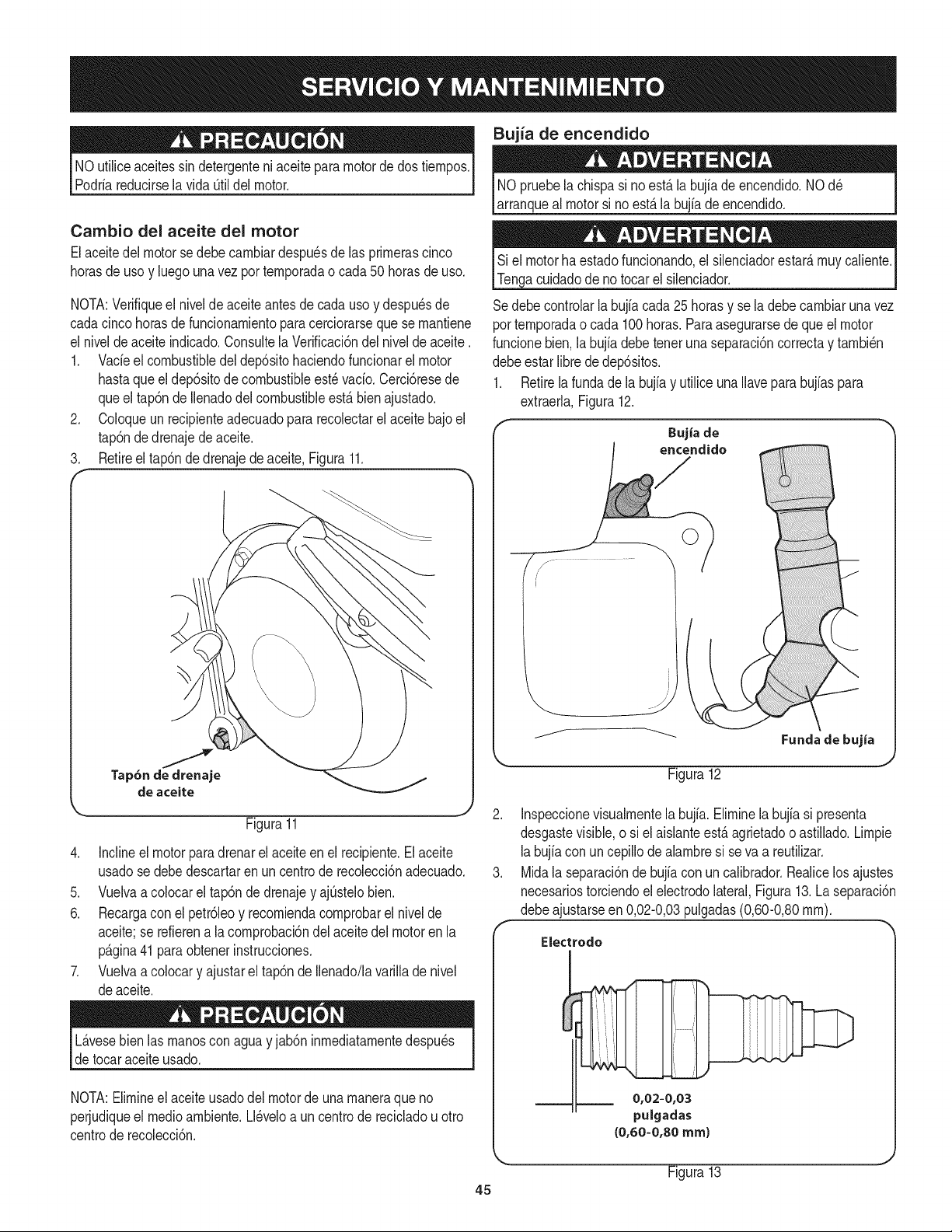
NO ufiliceaceitessin detergenteniaceiteparamotordedos fiempos,
Podriareducirselavida Qfildel motor,
Cambio del aceite del motor
Elaceitedel motorse debe cambiardespu_sde las primerascinco
horasde uso y luego una vez por temporadao cada 50horasde uso,
NOTA:Verifiqueel niveldeaceiteantesde cadauso y despu_sde
cadacinco horasdefuncionamientoparacerciorarseque se manfiene
el nivelde aceite indicado.Consultela Verificaci6ndel nivelde aceite,
1, Vadeel combustibledeldep6sitohaciendofundonarel motor
hastaqueel dep6sitodecombustibleest_vacio,Cerci6resede
queel tap6nde Ilenadodel combustibleest&bien ajustado,
2, Coloqueun recipienteadecuadopara recolectarel aceitebajoel
tap6nde drenajede aceite,
3, Retireel tap6ndedrenajedeaceite,Figura11,
%
Y
Tap6nde drenaje
de aceite
Figura11
4. Inclineel motorpara drenarel aceite en el recipiente.El aceite
usadose debedescartaren un centrode recolecci6nadecuado.
5. Vuelvaa colocarel tap6ndedrenajey aj[3stelobien.
6. Recargacon el petr61eoy recomiendacomprobarel nivelde
aceite;se refierena la comprobaci6ndelaceitedel motoren la
p_.gina41 para obtenerinstrucciones.
7. Vuelvaa colocary ajustarel tap6nde Ilenado/lavarilladenivel
deaceite.
L_.vesebien las manoscon agua yjab6n inmediatamentedespu_s
detocaraceiteusado.
NOTA:Elimineel aceiteusadodel motorde una maneraqueno
perjudiqueel medioambiente.Ll_veloa un centrode recicladou otro
centrode recolecci6n.
Bujia de encendido
NOpruebela chispasi no est,.la bujiade encendido.NOd_
arranqueal motorsi no est,. la bujia de encendido.
Si el motorhaestadofuncionando,el silenciadorestar_,muycaliente.
Tengacuidadodeno tocarel silenciador.
Sedebecontrolarla bujiacada25 horasy se la debe cambiaruna vez
portemporadao cada 100horas. Paraasegurarsede que el motor
funcionebien,la bujia debe tenet una separaci6ncorrectay tambi_n
debeestarlibrededep6sitos.
1. Retirela fundade la bujiay utiliceunaIlaveparabujiaspara
extraerla,Figura12.
BujJade
J
"----_ Fundade bujJa
Figura12
2. Inspeccionevisualmentela bujia. Eliminelabujia si presenta
desgastevisible,o si elaislanteest,.agrietadoo astillado.Limpie
labujiacon un cepillodealambresi se va a reutilizar.
3. Midala separaci6nde bujiaconun calibrador.Realicelos ajustes
necesariostorciendoel electrodolateral, Figura13.Laseparaci6n
debeajustarseen 0,02-0,03pulgadas(0,60-0,80ram).
Electrodo
0,02=0,03
pulgadas
(0,60-0,80 ram)
Figura13
45
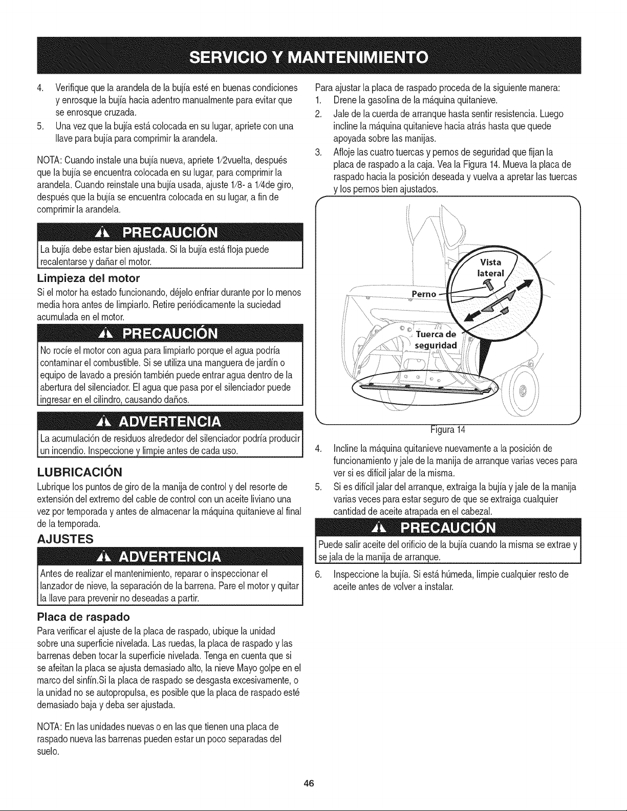
4. Verifiquequelaarandeladelabujiaest_enbuenascondiciones
yenrosquelabujiahaciaadentrornanualrnenteparaevitarque
seenrosquecruzada.
5. Unavezquelabujfaest,.colocadaensulugar,aprieteconuna
Ilaveparabujiaparacornprirnirlaarandela.
NOTA:Cuandoinstaleunabujfanueva,apriete1/2vuelta,despu_s
quelabujfaseencuentracolocadaensulugar,paracornprirnirla
arandela.Cuandoreinstaleunabujfausada,ajuste1/8-a1/4degiro,
despu_squelabujiaseencuentracolocadaensulugar,afinde
cornprirnirlaarandela.
Labujfadebeestarbienajustada.Silabujiaest,.fiojapuede
recalentarseyda_arelmotor.
Limpieza del motor
Siel motorhaestadofuncionando,d_jeloenfriardurantepor Io rnenos
mediahoraantes de lirnpiarlo.Retireperi6dicarnentela suciedad
acurnuladaen el motor.
No rode el motorcon aguaparalirnpiarloporqueel aguapodria
contarninarel combustible.Si se utilizaunarnangueradejardino
equipode lavadoa presi6ntarnbi_npuedeentraraguadentrode la
aberturadel silenciador.Elaguaquepasa porel silenciadorpuede
in_ndro, causandoda_os.
Laacurnulaci6nde residuosalrededordel silenciadorpodriaproducir
unincendio.Inspeccioney lirnpieantesdecada uso.
LUBRICACION
Lubriquelospuntosde giro de la rnanijade controly del resortede
extensi6ndel extrernodel cable decontrolcon un aceite livianouna
vezporternporaday antesde alrnacenarla rn_.quinaquitanieveal final
de laternporada.
AJUSTES
Antesde realizarel rnantenirniento,repararo inspeccionarel
lanzadorde nieve,la separaci6nde la barrena.Pareel motory quitar
la Ilaveparaprevenirno deseadasa partir.
Placa de raspado
Paraverificarel ajustede la placade raspado,ubiquela unidad
sobreuna superficienivelada.Lasruedas,la placaderaspadoy las
barrenasdebentocar la superficienivelada.Tengaen cuentaque si
se afeitanla placaseajusta dernasiadoalto,la nieveMayogolpe en el
marcodel sinfin.Sila placade raspadose desgastaexcesivarnente,o
la unidadnose autopropulsa,es posibleque la placade raspadoest_
dernasiadobajay debaser ajustada.
Paraajustarla placade raspadoprocedade la siguienternanera:
1. Drenela gasolinade la rn_.quinaquitanieve.
2. Jale dela cuerdade arranquehastasentirresistencia.Luego
inclinela rn_.quinaquitanievehaciaatr_.shastaquequede
apoyadasobrelas rnanijas.
3. Afiojelas cuatrotuercasy pernosdeseguridadquefijanla
placade raspadoa la caja.Vea la Figura14.Muevala placade
raspadohaciala posici6ndeseaday vuelvaa apretarlas tuercas
y los pernosbien ajustados.
4.
.
Figura14
Inclinelarn_.quinaquitanievenuevarnentea la posici6nde
funcionarnientoy jalede la rnanijadearranquevariasvecespara
vet si es dificiljalarde larnisrna.
Si es dificiljalar del arranque,extraigala bujia y jale dela rnanija
variasvecespara estar segurode que se extraigacualquier
cantidaddeaceiteatrapadaen el cabezal.
Puedesaliraceitedel orificio de la bujia cuandolarnisrnase extraey
sejalade la rnanijade arranque.
6. Inspeccionela bujia.Si est,.hQrneda,lirnpiecualquierrestode
aceiteantesde volverainstalar.
NOTA:En las unidadesnuevaso en lasque tienenunaplacade
raspadonuevalas barrenaspuedenestarunpoco separadasdel
suelo.
46

Cable de control
Es posibleque necesiterealizarajustesperi6dicosdebidoal
estiramientodelcablede controly de la correade transmisi6n
ocasionadoporeldesgaste.Sila barrenaparecetitubearmientras
gira,haga Io siguiente:
Elagujerosuperiorde la manijade controltieneencuentael ajustede
la tensi6ndel cable.Pararealizarel ajuste,desconecteel extremodel
cablede control del agujeroinferiorde la manijade control e insertelo
enel agujerosuperior.Inserteel cabledesdeel exteriorcomose
indicaen la Figura15.
f
Control
F
Cable _ t
Control
\
Figura15
Pruebela m_.quinaquitanievepara versi se Iograuna diferencia
apreciable.Siluegode realizadoel ajustedel cablede controlla
barrenasiguetitubeandoal girar,vea la Sustituci6nBelt paraobtener
las instruccionesparael reemplazodela correa.
Montaje del canal
Consultela secci6nMontajey Configuraci6nparaver las instrucciones
paraelajustedel montajedel canal.
CAMBIO DE CORREA
Correa de transmisi6n de la barrena
1. Parasacar la cubiertade la correasaquelos cincotornillos
hexagonalesque lasujetanal bastidor.Vea la Figura16.
\
/
/
Polealoca
..............Guardacorrea/'
"x\
Tornillos
de ca beza
hexagonal
Figura16
2. Retirelacorreasujet_.ndolaporla basede la poleade la barrena
y tire haciaafuera.
Paraobtenerla sustituci6nde SearsremosIlamaral 1-800-4-MY-
HOME.Preguntepor parte# 735-04033.
NOTA:Tire haciaabajola polea Iocapara soltarla correadedebajo
del guardacorrea.Yeala Figura17.
Polea de la
barrena
Polea del
motor
!
//
Figura17
J
Paravolvera colocarlacorreasiga estasinstruccionesy consultela
Figura17:
1. Tire haciaabajolapoleaIoca.
2. Ubiquela correaencimade la poleade la barrenay debajodel
guardacorrea.
3. Coloquela correaalrededorde la poleadelmotor.
47
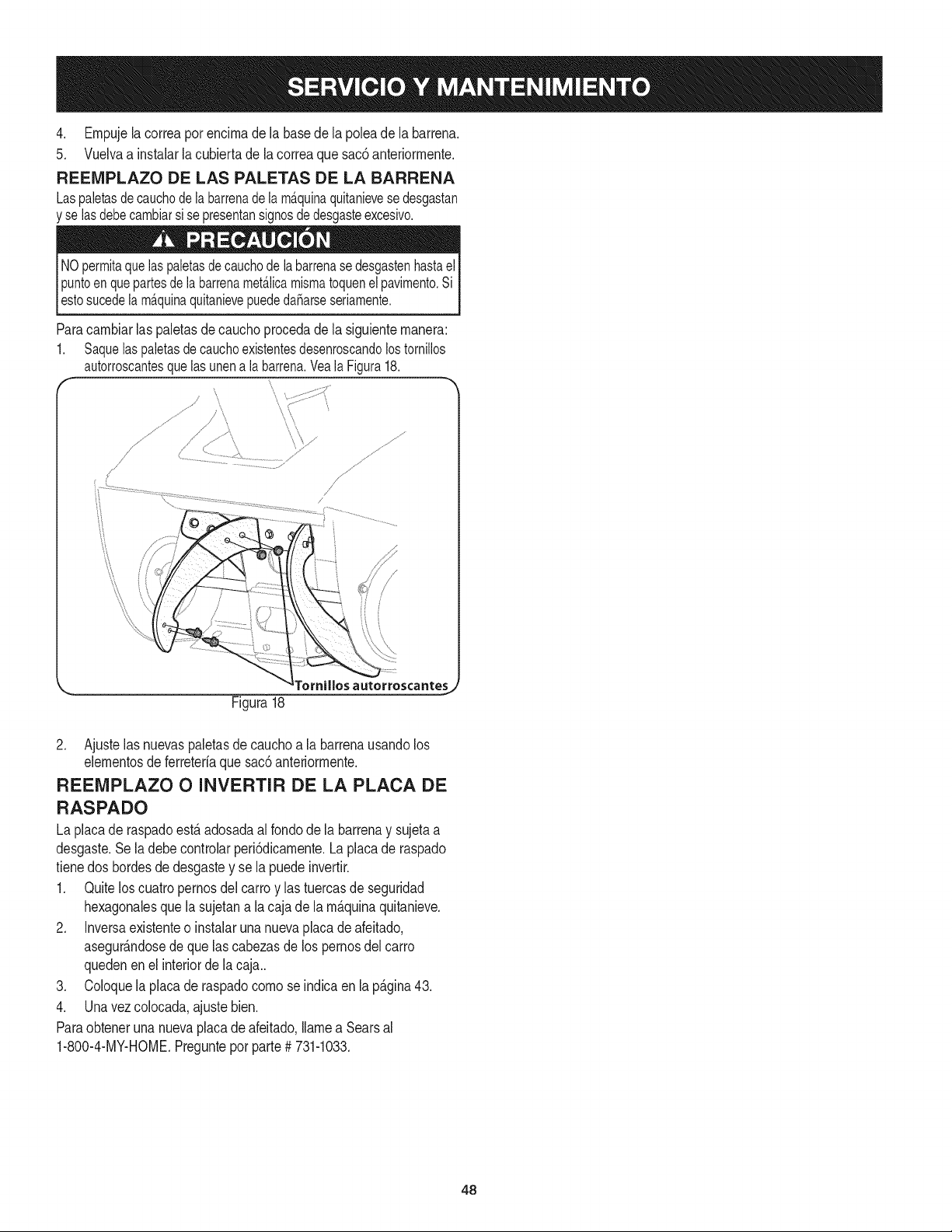
4. Empujela correaporencimadela basede la poleade la barrena.
5. Vuelvaa instalarla cubiertade la correaque sac6anteriormente.
REEMPLAZO DE LAS PALETAS DE LA BARRENA
Laspaletasde cauchode labarrenadelam&quinaquitanievesedesgastan
y selasdebecambiarsi sepresentansignosde desgasteexcesivo.
NOpermitaquelaspaletasdecauchodelabarrenasedesgastenhastael
puntoen quepartesde la barrenamet_.licamismatoquenel pavimento.Si
_estosucedeam_.qunaqutanevepuededa_arseseramente.
Paracambiarlas paletasde cauchoprocedadela siguientemanera:
1. Saquelaspaletasdecauchoexistentesdesenroscandolostornillos
autorroscantesquelasunena labarrena.Veala Figura18.
\\
f
\\
Figura18
autorroscante_
2. Ajustelas nuevaspaletasde cauchoa la barrenausandolos
elementosde ferreteriaque sac6 anteriormente.
REEMPLAZO O INVERTIR DE LA PLACA DE
RASPADO
La placade raspadoest&adosadaal fondodela barrenay sujetaa
desgaste.Sela debecontrolarperi6dicamente.Laplacade raspado
tienedos hordesde desgastey se la puedeinvertir.
1. Quitelos cuatropernosdel carroy las tuercasde seguridad
hexagonalesquela sujetana la cajade la m_.qulnaquitanieve.
2. Inversaexistenteo instalaruna nuevaplacade afeitado,
asegur_.ndosede que las cabezasde los pernosdelcarro
quedenenel interiorde la caja..
3. Coloquela placade raspadocomose indicaen la p_.gina43.
4. Unavezcolocada, ajustebien.
Paraobteneruna nuevaplacade afeitado,Ilamea Searsal
1-800-4-MY-HOME.Preguntepor parte# 731-1033.
48
Si nose va a utilizarelequipodurante30 dfas o rn_.s,o si es el finalde la ternporadade nievey ya no existeposibiNdaddeque nieve,es
necesarioalrnacenarel equipode rnaneraadecuada.Sigalas instruccionesde alrnacenarnientoque se indicana continuaci6nparagarantizarel
rendirnientorn_.xirnode la rn_.quinaquitanieveduranternuchosa_osrn_.s.
PREPARACI6N DEL MOTOR
Los rnotoresalrnacenadosrn_.sde 30 dfasnecesitanser drenados
decombustibleparaevitarquese deterioreny se forrnegornaen el
sisternacombustibleo en laspiezasprincipalesdel carburador.Si la
gasolinaen sumotorse deterioraduranteel alrnacenarniento,debe
repararo reernplazarel carburadory otroscornponentesdel sisterna
combustible.
1. Elirninetodoel combustibledeldep6sitohaciendofuncionarel
motorhastaquesedetenga.
2. Carnbieel aceitedelmotor.
3. Extraigala bujfade encendidoy viertaenel cilindro
aproxirnadarnente1onza(30 rnl)de aceitepara motorlirnpio.Tire
variasvecesdel arrancadorde retrocesoparadistribuirel aceitey
reinstalelabujfa.
4. Lirnpielos residuosacurnuladosalrededordel motor,y debajo,
alrededor,y detr_.sdel silenciador.Apliqueunacapadelgadade
aceiteen todaslas _.reasque puedenNegara oxidarse.
5. Alrnaceneel motorenun sectorlirnpio,secoy bien ventilado,
lejosde cualquierartefactoque funcionecon unallamao luz
pilotocornohornos,calentadoresdeaguao secadoresde ropa.
Evitecualquiersectorcon un motorel_ctricoqueproduzca
chispaso donde se utilicenherrarnientaselectricas.
Nuncaalrnacenela rn_.quinaquitanievecon combustibleen el
tanqueen un espaciocerradoo en_.reascon pocaventilaci6n,
dondelos gasesdel combustiblepuedanalcanzarel fuego,chispas
o unaluz pilotocornola que tienenalgunoshornos,calentadoresde
agua,secadoresde ropao algOnotto dispositivoa gas.
6. Si es posible,evite sectoresde alrnacenarnientoconrnucha
hurnedad.
7. Mantengael motorniveladocuandoIo alrnacene.Lainclinaci6n
delmotorpuederesultaren fugasdecombustibleoaceite.
PREPARACI6N DE LA M.&.QUINA
QUITANIEVE
Si no seva a usar la rn&quinaquitanievedurante30 dfas o rn&s,siga
las siguientesinstruccionesincluidasa continuaci6n.
1. Alrnaceneel equipoen un _.readespejaday seca.
2. Si el alrnacenarnientode la nievelanzadoren un _.reasin
ventilaci6n,inoxidableslas partesrnet_.Ncasde la rn_.quinacon
un aceiteligeroo recubrirnientode silicona.
3. Lirnpieel exteriordel motory de la rn_.quinaquitanieve.
4. Lubriquelos puntospivote,sobreel controly rnanejarla exten-
si6n de prirnaveraa finalesde cablede controlcon unaceite
ligero.
49
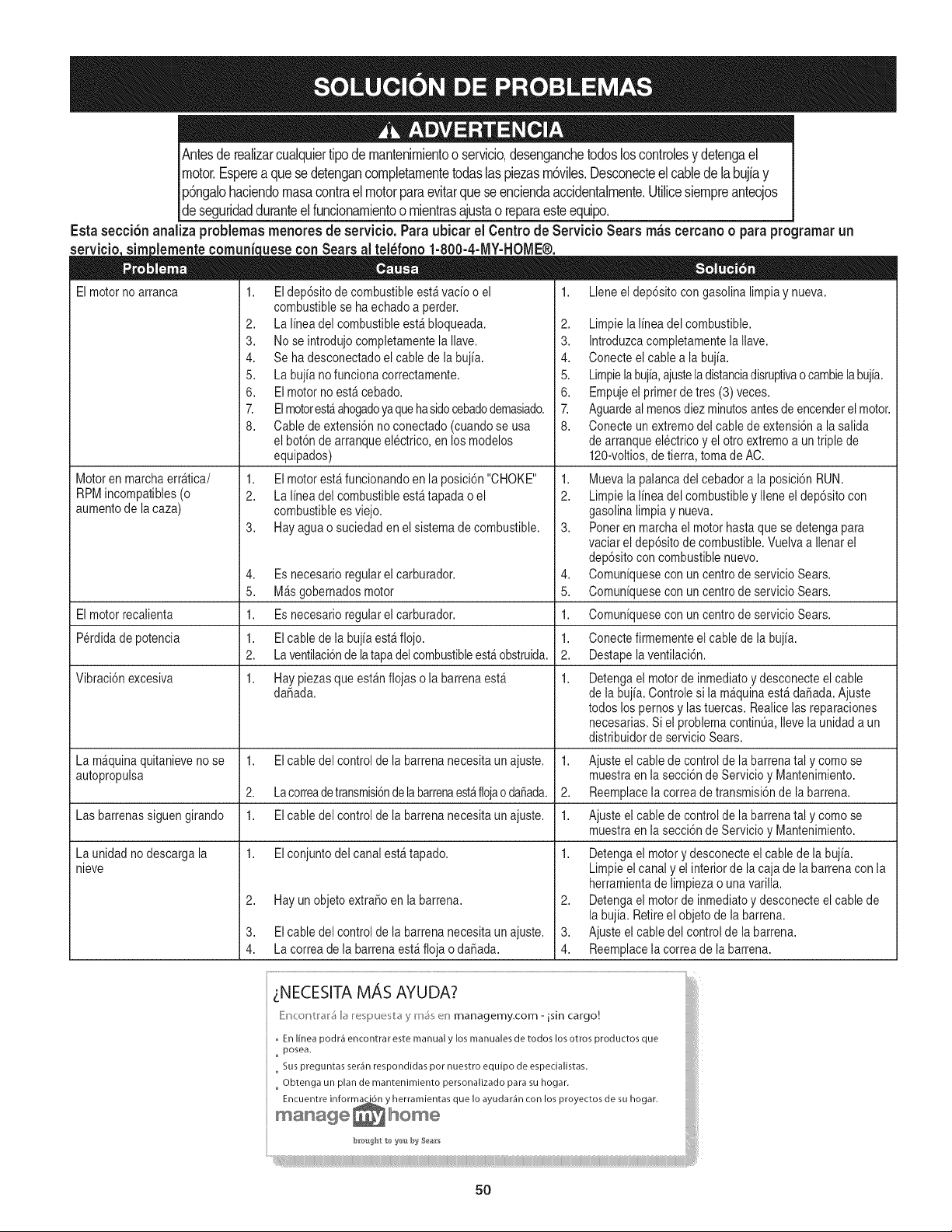
AntesderealizarcualquiertipodemantenJmientooservicio,desenganchetodosloscontrolesydetengael
motor.Espereaquesedetengancompletamentetodaslaspiezasm6viles.Desconecteelcabledelabujfay
p6ngalohaciendomasacontraelmotorparaevitarqueseenciendaaccidentalmente.Utilicesiempreanteojos
[de segurdad durante e funconam ento o m entras ajusta o reparaeste equ pc.
Esta secci6n analiza problemas menores de servicio. Para ubicar el Centro de Servicio Sears m_iscercano o para programar un
Elmotorno arranca
Motoren marchaerrAtica/
RPMincompatibles(o
aumentode la caza)
Elmotorrecalienta
P@didade potencia
Vibraci6nexcesiva
1. El dep6sitode combustibleest_vacio o el
combustiblese ha echadoa perder.
2. La linea del combustibleest_bloqueada.
3. Nose introdujocompletamentela Ilave.
4. Se ha desconectadoel cable de la bujia.
5. La bujia nofunciona correctamente.
6. El motorno est_cebado.
7. El motorest_ahogadoyaquehasidocebadodemasiado.
8. Cable de extensi6nnoconectado(cuandose usa
el bot6nde arranqueelectrico,en losmodelos
equipados)
1. El motorest_ funcionandoen la posici6n"CHOKE"
2. La linea del combustibleest_tapada o el
combustiblees viejo.
3. Hayagua o suciedaden el sistemade combustible.
4. Es necesarioregularel carburador.
5. M_s gobernadosmotor
1. Es necesarioregularel carburador.
1. El cablede la bujia est_flojo.
2. La ventilaci6nde la tapadelcombustibleest_ obstruida.
1. Haypiezas queest_nflojas o labarrenaest_
dafiada.
1. Llene el dep6sitocon gasolinalimpia y nueva.
2. Limpie la linea del combustible.
3. Introduzcacompletamentela Ilave.
4. Conecteel cablea labujia.
5. Limpielabujia,ajusteladistanciadisruptivaocambielabujia.
6. Empujeel primerde tres (3) veces.
7. Aguardeal menosdiez minutosantesde encenderelmotor.
8. Conecteun extremodel cablede extensi6na la salida
de arranqueel@tricoy el otro extremoa un triple de
120-voltios,de tierra,toma de AC.
1. Mueva la palancadel cebadora la posici6nRUN.
2. Limpie la linea del combustibley Ileneel dep6sitocon
gasolinalimpia y nueva.
3. Poneren marchaelmotor hastaquese detengapara
vaciarel dep6sitode combustible.Vuelvaa Ilenarel
dep6sitocon combustiblenuevo.
4. Comuniqueseconun centrode servicioSears.
5. Comuniqueseconun centrode servicioSears.
1. Comuniquesecon un centrode servicioSears.
1. Conectefirmementeel cablede la bujia.
2. Destapela ventilaci6n.
1. Detengae[ motorde inmediatoy desconecteelcable
de la bujia.Controlesi la m_quinaest_ da_ada.Ajuste
todos lospernosy lastuercas. Realicelas reparaciones
necesarias.Siel problemacontinQa,Ilevela unidada un
distribuidorde servicioSears.
La m_quinaquitanieveno se 1. Elcable del control de la barrenanecesitaun ajuste. 1. Ajusteel cablede control de la barrenatal y comose
autopropulsa muestraen la secci6nde Servicio y Mantenimiento.
2. Lacorreadetransmisi6ndelabarrenaestMIojao dafiada. 2. Reemplacela correade transmisi6nde la barrena.
Las barrenassiguen girando 1. Elcable del control de la barrenanecesitaun ajuste. 1. Ajusteel cablede controlde la barrenatal y comose
muestraen la secci6nde Servicio y Mantenimiento.
La unidad no descargala 1. Elconjuntodel canalest_tapado. 1.
nieve
2. Hayun objeto extra_oen la barrena.
3.
4.
Elcable del control de la barrenanecesitaun ajuste.
La correa de la barrenaest_ floja o daffada.
Detengael motory desconecteel cablede la bujia.
Limpieel canal y el interiorde lacaja de labarrenacon la
herramientade limpiezao unavarilla.
2. Detengael motorde inmediatoy desconecteelcable de
la bujia. Retireel objeto de la barrena.
3. Ajusteel cabledel control de la barrena.
4. Reemplacela correade la barrena.
LNECESITAMA,S AYUDA?
_}:won_rar_ la _,_;puu_;b_ y ms_ _,r_managemy.com - isin cargo!
,, En Ifnea podr& encontrar este manual y los manuales de todos los otros productos que
posea.
,, Sus preguntas ser_n respondidas por nuestro equipo de especialistas.
Obtenga un plan de mantenimiento personalizado para su hogar.
con los proyectos de su hogar.
brought to Feu b 2 Seazs
50

51
MTD CONSUMER GROUP, iNC. (MTD), el Bordo de Recursos de Aire de California (CARB)
y la Agencia de Protecci6n Medioambiental de Estados Unidos (U. S. EPA)
Declaraci6n de Garantia del Sistema de Control de Emisiones
(Derechos y obligaciones del propietario seg_n la garantia contra defectos)
LACOBERTURADESISTEMADECONTROLDEEMISIONESAPLICABLEA MOTORESCERTIFICADOSCOMPRADOSENCALIFORNIA
EN2005 Y A PARTIRDE ENTONCES,QUESON USADOSEN CALIFORNIA,Y HASTAANO2005DE MODELOCERTIFICADOY MOTORES
POSTERIORESQUESON COMPRADOSY USADOSENOTRAPARTEEN LOSESTADOSUNIDOS.
Californiayen otra parteen la Coberturade Garantiade DefectosdeControlde Emisi6nde los EstadosUnidos
El Bordode Recursosde Airede California(CARB),la U.S. EPAy MTDsecomplacenen explicarla garantiadel sistemade controlde emisiones
de su motorparaequipotodo terreno,modelo,aSo2005y versionesposteriores.EnCalifornia,los nuevosmotorespequeSosparaequipotodo
terrenose debendise5ar,fabricary equiparparacumplir conest_.ndaresde antinieblat6xicade estados.En otraparteen los EstadosUnidos,
el nuevono camino,motoresdeignici6nde chispacertificadospara el modelo2005y m_.starde,debeencontrareljuegode est_.ndaressimilar
adelantepor los EstadosUnidos.EPA.MTDdebegarantizarel sistemadecontrolde emisionesdesu motorpor el periodode tiempoindicadom&s
abajo,siemprey cuandono hayaexistidousoincorrecto,negligencianimantenimientoinadecuadode su motorpequeBoparaequipotodoterreno.
El sistemadecontrolde emisionespuedeincluirpiezascomo,porejemplo,el carburador,sistemadeinyecci6nde combustible,el sistemade
encendido,el catalizador,losdep6sitosde combustible,abastecede combustiblelineas, gorrasde combustible,v&lvulas,latas,filtros,mangueras
devapor,abrazaderas,conectoresy otroscomponentesrelacionadoscon lasemisiones.
Dondeexistaunacondici6ncubiertaporla garantia,MTDreparar&su motorpequeBoparaequipotodoterrenosincostoalgunoincluyendoel
diagn6stico,laspiezasy la manode obra.
COBERTURA DE LA GARANTJA DEL FABRICANTE:
Estesistemade controldeemisionesse garantizapor el t@rminodedos a5os.Si algunapiezade su motorrelacionadacon lasemisioneses
defectuosa,MTD reparar&o sustituir&dichapieza.
RESPONSABJLIDADES DEL PROPIETARIO SEGUN LA GARANTJA:
Comopropietariode un motorpequeSode equipotodoterreno,ustedes responsablede realizarel mantenimientonecesarioquefigura enel
manualdel propietario. MTDle recomiendaqueconservetodoslos recibosquecubrenlos serviciosdemantenimientodel motorpeque5opara
equipotodoterreno,noobstanteIo cual MTDno podr&denegarel cumplimientode la garantiaQnicamentepor lafaltade reciboso porsu imposi-
bilidaddeasegurarque se realizar_.ntodoslos serviciosde mantenimientoprogramado.
Comopropietariodel motorpeque5oparaequipotodo terreno,sinembargo,ustedtambi@ndebesaberque MTDpuededenegarlacoberturadela
garantiasi su motorpeque5oparaequipotodoterrenoo unapiezadel mismofallandebido a usoincorrecto,negligencia,mantenimientoindebido
o a modificacionesno aprobadas.
Ustedes responsablede presentarlacortadoradecespedal centrode distribuci6no de mantenimientode MTDCONSUMERGROUP,INC.tan
prontocomo aparecierael problem& Lasreparacionescubiertaspor lagarantiasedebenIlevaracabo en un lapsorazonableque noexcedade
30dias.Si desearealizaralgunaconsultacon respectoa la coberturade la garantia,debe ponerseen contactocon su distribuidorlocalde MTD.
Paracomunicarseconla Linea de Asistenciaal Clientede Distribuidoresde MTD,Ilameal nQmero(877)282-8684.
REQUERJMJENTOS DE GARANTJA SOBRE DEFECTOS PARA MOTORES PEQUENOS DE EQUJPO TODO TERRENO
DE 1995YVERSJONES POSTERJORES:
Estasecci6nse aplicaa motorespeque5osde equipotodo terrenode 1995y versionesposteriores.Elperiododegarantiacomienzaa partirde la
fechaen queel motoro elequiposeentreganal compradorfinal.
(a) Coberturade la garantiacontraemisionesgenerales
MTDgarantizaal compradorfinaly acada compradorsubsiguientequeel motor:
(1)hasido diseSado,construidoy equipadode maneraquecumplacontodas las regulacionesvigentesadoptadaspor el Departamentode los
RecursosdeAire envirtuda suautoridadconferidaen los capitulos1 y 2, Parte5, Divisi6n26 del C6digode Saludy Seguridad;y
(2)est,. librede defectosen los materialesyen la manode obra que causenla falla deunapiezabajo garantiaque seaid@nticaentodos los
aspectosmaterialesa la piezacomoaparecedescriptaen la aplicaci6ndelfabricantedel motorpara certificaci6npor unperiododedos a5os.
_arantia sobre piezasrelacJonadasconemisJonesse interpretar_,de la sJguientemanera:
(1)Cualquierpiezacubiertaporgarantiaquenoest@programadaparasu reemplazosegQnel mantenimientorequeridoenlas instrucciones
escritasdela Subsecci6n(c) debeestargarantizadapor unperiodode garantiadefinidoen la Subsecci6n(a) (2). Si la piezafalladurante
el periododecoberturadela garantia,lamismaser_.reparadao reemplazadapor MTD de acuerdocon la Subsecci6n(4) a continuaci6n.
Cualquierpiezareparadao reemplazadasegQnla garantiasegarantizarB,porel restodelperiodode garantia.
(2) Cualquierpiezacubiertaporgarantiaque est@programadasoloparainspecci6nregularen las instruccionesescritasde la Subsecci6n
(c) debe estargarantizadapor un periodode garantiadefinidoenla Subsecci6n(a) (2). Unadeclaraci6nen dichasinstruccionespor escrito
alefectode "reparaci6no reemplazosegQnseanecesario"no reducir_,elperiodode coberturade la garantia.Cualquierpiezareparadao
reernplazadasegQnlagarantiasegarantizar_,porelrestodelperiododegarantia.
(3) Cualquierpiezagarantizadaqueest_prograrnadaparareernplazosegQnelrnantenirnientorequeridodeconforrnidadconlasinstruc-
clonesescritasdelaSubsecci6n(c)segarantizaporelperiododetiernpoanterioralaprirnerafechadereernplazoprograrnadaparaesa
pieza.Silapiezafallaantesdelprimerreernplazoprogramatic,larnisrnaser_.reparadaoreernplazadaporMTDdeacuerdoconlaSubsecci6n
(4)acontinuaci6n.Cualquierpiezareparadaoreernplazadabajogaranfiasegarantizar_,porelrestodelperiodoanterioralprimerreernplazo
programaticpuntualparaesapieza.
(4)Lareparaci6noelreernplazodecualquierpiezagarantizadadeconforrnidadconlasdisposicionesdelagaranfiaqueaquiseestipulase
deberealizarenuncentrodegaranfiasincostoalgunoparaelpropietario.
(5)SinperjuiciodelasdisposicionesdelaSubsecci6n(4)anterior,losserviciosoreparacionescubiertosporlagaranfiadebensersurnin-
istradosportodosloscentrosdedistribuci6ndeMTDquetenganlafranquiciapararealizarreparacionesyrnantenirnientoalosrnotoresen
cuesti6n.
(6)ElpropietarionodebeafrontarningQncargoparatrabajosdediagn6sticoqueIlevenalaconclusi6ndequeunapiezabajogaranfiapresenta
efectivarnentedefectos,siernpreycuandodichodiagn6sticoseaIlevadoacaboenuncentrocubiertoporlagarantia.
(7)Elfabricantedelmotoresresponsableporda_oscausadosaotroscornponentesdernotoresderivadosdelafallabajogaranfiadecualquier
piezagarantizada.
(8)DurantetodoelperiododegaranfiadelmotordefinidoenlaSubsecci6n(a)(2),MTDrnantendr_,unsurninistrodepiezascubiertaspor
garantiasuficienteparasatisfacerladernandaesperadaparatalespiezas.
(9)Cualquierpiezadereernplazosepodr_,usarparaelcurnplirnientodelrnantenirnientooreparacionesbajogaranfia,ysesurninistrar_,sin
cargoalpropietario.Dichousonoreducir_,lasobligacionesdegarantiadeMTD.
(10)Nosepodr_.nusarpiezasadicionalesnirnodificadasquenoest_nexentasdeacuerdoconelDepartarnentodelosRecursosdelAire(Air
ResourcesBoard).Elusodepiezasadicionalesornodificadasnoexentasser_.causasuficienteparaanularunreclarnobajogaranfiarealizado
deacuerdoconestearticulo.Elfabricantedelmotornotendr_,responsabilidad,enconforrnidadconestearticulo,degarantizarfallasdepiezas
garantizadasquefuerencausadasporelusodeunapiezanoexentaadicionalornodificada.
.(c)MTDincluir_,una copiade lasiguientelistade piezasbajogarantiacontraernisionescon cadanuevomotor,utilizandolas partesde la lista
a_plicablesal motor.
(1)Sisternadernedici6ndecombustible
• Sisternade rnejorapara inicioenfrio (cebadosuave)
• Carburadory cornponentesinternos
• Bornbade combustible
• Dep6sitode combustible
(2) Sisternadeinducci6ndeaire
• Filtrode aire
• Colectorde entrada
(3) Sisternadeencendido
• Bujia(s)
• Sisternade encendidopor magneto
(4)Sisternadeescape
• Catalizador
• SAI (v_Jvulade Ca_a)
(5) Cornponentesvarios utilizadosen el sisternaanterior
• V_Jvulase interruptoresde vado, ternperatura,posici6nsensiblesal tiernpo
• Conectoresy rnontajes
(6)Controlde Evaporative
• Manguerade CombustiblecertificadaparaARB evaporativeernisi6nde 2006.
• Abrazaderasde Manguerade Combustible
• Gorrade combustibleatada
• Latade carb6n
• Lineasdevapor
GD0C-100174Rev.B
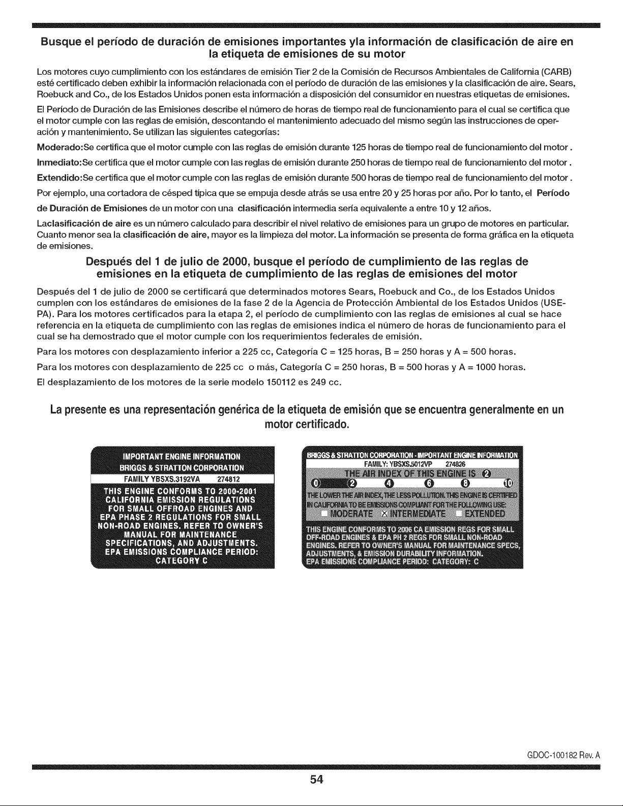
Busque el periodo de duraci6n de emisiones importantes yla informaci6n de clasificaci6n de aire en
la etiqueta de emisiones de su motor
Los motores cuyo cumpiimiento con los estAndares de emisi6n Tier 2 de la Comisi6n de Recursos Ambientales de California (CARB)
est6 certificado deben exhibir la informaci6n relacionada con el perJodo de duraci6n de las emisiones y la clasificaci6n de aire. Sears,
Roebuck and Co., de los Estados Unidos ponen esta informaci6n a disposici6n deJ consumidor en nuestras etiquetas de emisiones.
El Periodo de Duraci6n de las Emisiones describe el nQmero de horas de tiempo real de funcionamiento para el cual se certifica que
el motor cumple con las reglas de emisi6n, descontando el mantenimiento adecuado deJ mismo segQn las instrucciones de oper-
aci6n y mantenimiento. Se utilizan las siguientes categorias:
Moderado:Se certifica que el motor cumpie con las reglas de emisi6n durante 125 horas de tiempo real de funcionamiento deJ motor.
Inmediato:Se certifica que el motor cumple con las reglas de emisi6n durante 250 horas de tiempo real de funcionamiento deJ motor.
Extendido:Se certifica que el motor cumple con las reglas de emisi6n durante 500 horas de tiempo real de funcionamiento deJ motor.
Por ejemplo, una cortadora de c6sped tJpica que se empuja desde atrAs se usa entre 20 y 25 horas por afio. Por Io tanto, el Periodo
de Duraci6n de Emisiones de un motor con una clasificaci6n intermedia seria equivalente a entre 10 y 12 afios.
Laclasificaci6n de aJre es un nQmero calculado para describir eJnivel reiativo de emisiones para un grupo de motores en particular.
Cuanto menor sea Jaclasificaci6n de aire, mayor es JaJimpieza deJ motor. La informaci6n se presenta de forma gr&fica en Jaetiqueta
de emisiones.
Despu_s del 1 de julio de 2000, busque el periodo de cumplimiento de las reglas de
emisiones en la etiqueta de cumplimiento de las reglas de emisiones del motor
Despu_s deJ 1 de julio de 2000 se certificar_, que determinados motores Sears, Roebuck and Co., de los Estados Unidos
cumpien con los estAndares de emisiones de la fase 2 de la Agencia de Protecci6n Ambiental de los Estados Unidos (USE-
PA). Para los motores certificados para la etapa 2, el periodo de cumpiimiento con las reglas de emisiones al cual se hace
referencia en la etiqueta de cumpiimiento con las reglas de emisiones indica el nQmero de horas de funcionamiento para el
cuaJ se ha demostrado que el motor cumpie con los requerimientos federales de emisi6n.
Para los motores con desplazamiento inferior a 225 cc, Categoria C = 125 horas, B = 250 horas y A = 500 horas.
Para los motores con desplazamiento de 225 cc o mAs, Categoria C = 250 horas, B = 500 horas y A = 1000 horas.
El despiazamiento de los motores de la serie modelo 150112 es 249 cc.
La presente es una representaci6n gen_rica de la etiqueta de emisi6n que se encuentra generaimente en un
motor certificado.
FAMILYYBSXS.3192VA 274812
GDOC-100182Rev.A
54
Felicitacionespor haberrealizadouna adquisici6ninteligente.El
productoCraftsman@queha adquiridoest_dise_adoy fabricado
parabrindarrnuchosa_osde funcionarnientoconfiable.Perocorno
todoslos productosa vecespuederequerirde reparaciones.Esen
esernornentocuandoel disponerde un Acuerdode protecci6npara
reparacionesle puedeahorrardineroy problernas.
A continuaci6nsedetallanlos puntosincluidosenel Acuerdo:
• Servicio experto prestadopor nuestros10,000especialistasen
reparacionesprofesionales
• Servicio ilirnitadosin cargoparalaspiezasy la rnanode obra en
todaslas reparacionescubiertas
• Reernplazodel productohasta1500d61aressi no es posible
repararel productocubierto
• Descuentode 10%del precionormaldel servicioy delas piezas
relacionadascon el rnisrnoqueno est_ncubiertasporel acuerdo;
adern&s,10%del precionormalde la verificaci6nde rnanten-
irnientopreventivo
• Ayudar_pida pot tel_fono- IoIlarnarnosResoluci6nR_pida- el
apoyotelef6nicode un Charnuscaal representante.Pienseen
nosotroscornoel manual"de undue_ohablador."
Unavezadquiridoel Acuerdo,puedeprograrnarel serviciocon
tan s61orealizarunaIlarnadatelef6nica.PuedeIlarnaren cualquier
mornentodeldia o dela nocheo prograrnarun servicioen linea.
ElAcuerdode Protecci6nde Reparaci6nes unacornprasin riesgo.
Siustedanulaporalgunaraz6nduranteel periodode garantiade
producto,proporcionarernosun reernbolsoIleno.O,un reernbolso
prorrateadoen cualquiermornentodespu_sdelperiodode garantia
de productoexpira,iAdquieraboysu acuerdode protecci6npara
reparaciones!
Seaplican deterrninadaslimitaciones y exclusiones.Paraobtener
inforrnaci6nadicional y preciosen los Estados UnidosIlarne al
1-800-827-6655.
El*Coverage en Canad_variaen algunosarticulos. Paradetalles
Ilenosla IlarnadaCharnuscaCanad_en 1-800-361-6665.
Servicio de instalaci6nde Sears
Sideseasolicitarla instalaci6nprofesionalde Searsde aparatos
dorn_sticos,dispositivosparaabrirportones,calentadoresde agua
y otrosarficulosdorn_sticosirnportantes,en los EstadosUnidoso
Canad_Ilarneal 1-800-4-MY-HOME®.
55

Your Home
For expert troubleshooting and home solutions advice:
www.managemyhome.com
For repair - in your home - of all major brand appliances,
lawn and garden equipment, or heating and cooling systems,
no matter who made it, no matter who sold it!
For the replacement parts, accessories and
owner's manuals that you need to do-it-yourself.
For Sears professional installation of home appliances
and items like garage door openers and water heaters.
1-800-4-MY-HOME ® (1-800-469-4663)
Call anytime, day or night (U.S.A. and Canada)
www.sears.com www.sears.ca
Our Home
For repair of carry-in items like vacuums, lawn equipment,
and electronics, call anytime for the location of your nearest
Sears Parts & Repair Service Center
1-800-488-1222 (U.S.A.) 1-800-469-4663 (Canada)
www.sears.com www.sears.ca
To purchase a protection agreement on a product serviced by Sears:
1-800-827-6655 (U.S.A.) 1-800-361-6665 (Canada)
Para pedir servicio de reparaci6n
a domicilio, y para ordenar piezas:
1-888-SU-HOGAR ®
(1-888-784-6427)
Au Canada pour service en fran£ais:
1-800-LE-FOYER M°
(1-800-533-6937)
www.sears.ca
® Registered Trademark / TMTrademark / SM Service Mark of Sears Brands, LLC
SM
® Marca Registrada / TMMarca de F&brica / Marca de Servicio de Sears Brands, LLC
MCMarque de commerce / MDMarque depos6e de Sears Brands, LLC © Sears Brands, LLC