Loading ...
Loading ...
Loading ...
5
Parts Supplied
Check that all parts are included.
■ Anti-tip bracket kit
NOTE: Anti-tip bracket must be securely mounted to
suboor. Thickness of ooring may require longer screws
toanchor bracket to suboor. Longer screws are available
from your local hardware store. See the “Install Anti-Tip
Bracket” section.
■ Burner grates
■ Burner caps
■ Griddle drip tray (on griddle models)
Parts Needed
■ All models must be installed with a backguard if installing
at zero clearance to a combustible back wall surface such
as drywall. See “Cabinet Dimensions” in the “Location
Requirements” section for installation requirements.
Check local codes and consult gas supplier. Check existing gas
supply and electrical supply. See the “Electrical Requirements”
and “Gas Supply Requirements” sections.
It is recommended that all electrical connections be made by
alicensed, qualied electrical installer.
Location Requirements
IMPORTANT: Observe all governing codes and ordinances.
Donot obstruct ow of combustion and ventilation air.
■ It is the installer’s responsibility to comply with installation
clearances specied on the model/serial/rating plate. The
model/serial/rating plate is located under the console on
theright-hand side.
■ It is recommended that a 585 CFM (993.9 m
3
/hr) or larger
range hood beinstalled above the range.
■ Follow the range hood or microwave hood combination
installation instructions for dimensional clearances above the
cooktop surface.
■ Recessed installations must provide complete enclosure
ofthe sides and rear of the range.
■ All openings in the wall or oor where range is to be installed
must be sealed.
■ Do not seal the range to the side cabinets.
■ Cabinet opening dimensions that are shown must be used.
Given dimensions are minimum clearances.
■ The anti-tip bracket must be installed. To install the anti-tip
bracket shipped with the range, see the “Install Anti-Tip
Bracket” section.
■ Grounded electrical supply is required. See the “Electrical
Requirements” section.
■ Proper gas supply connection must be available. See the
“Gas Supply Requirements” section.
■ Contact a qualied oor covering installer to check that the
oor covering can withstand at least 200°F (93°C). Use an
insulated pad or 1/4" (6.4 mm) plywood over carpet and
under range if installing range over carpeting.
IMPORTANT: To avoid damage to your cabinets, check with
your builder or cabinet supplier to make sure that the materials
used will not discolor, delaminate, or sustain other damage. This
oven has been designed in accordance with the requirements
of UL and CSA International and complies with the maximum
allowable wood cabinet temperatures of 194°F (90°C).
Mobile Home - Additional Installation Requirements
The installation of this range must conform to the Manufactured
Home Construction and Safety Standard, Title24CFR,
Part 3280 (formerly the Federal Standard for Mobile Home
Construction and Safety, Title 24, HUD Part 280).When such
standard is not applicable, use the Standard forManufactured
Home Installations, ANSI A225.1/NFPA 501A or local codes.
In Canada, the installation of this range must conform with
thecurrent standards CAN/CSA-A240-latest edition or with
localcodes.
Mobile Home Installations Require:
■ When this range is installed in a mobile home, it must be
secured to the oor during transit. Any method of securing
the range is adequate as long as it conforms to the
standards listed above.
■ The installation of appliances designed for recreational park
trailers must conform with state or other codes or, in the
absence of such codes, with the Standard for Recreational
Park Trailers, ANSI A119.5.
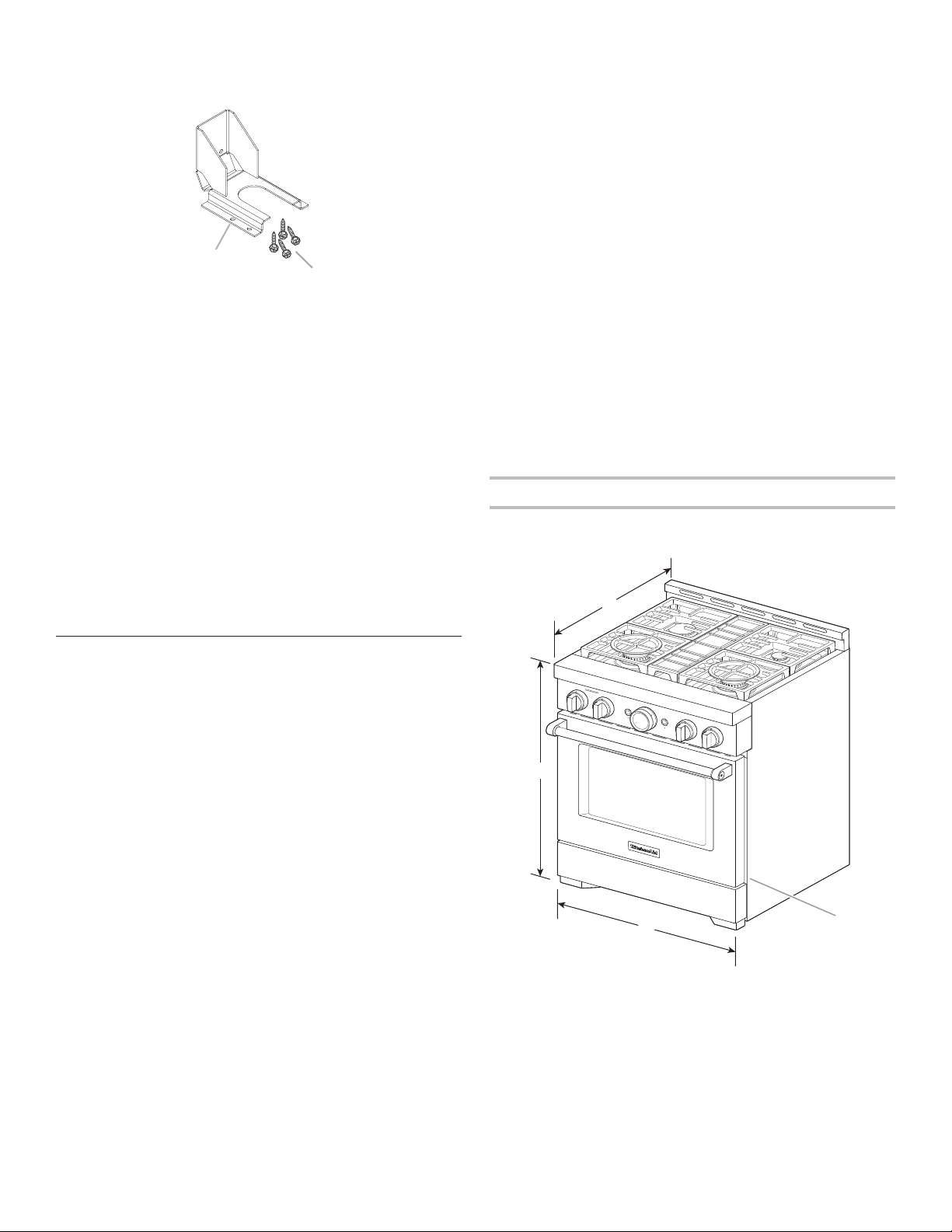
Product Dimensions
NOTE: Cooktop features may differ.
30" (76.2 cm) models
A
B
A. Anti-tip bracket
B. #8-18 x 1" (2.5cm) Phillips head screws (4)
A
C
B
D
A. 27
3
/
4
" (70.5 cm) depth with control panel (See NOTE.)
B. 36" (91.4 cm) range height when sitting on the wheels
C. 29
7
/
8
" (75.7 cm) width
D. Model/serial/rating plate location/SAID label
(located on front side panel)
Loading ...
Loading ...
Loading ...