Loading ...
Loading ...
Loading ...
15
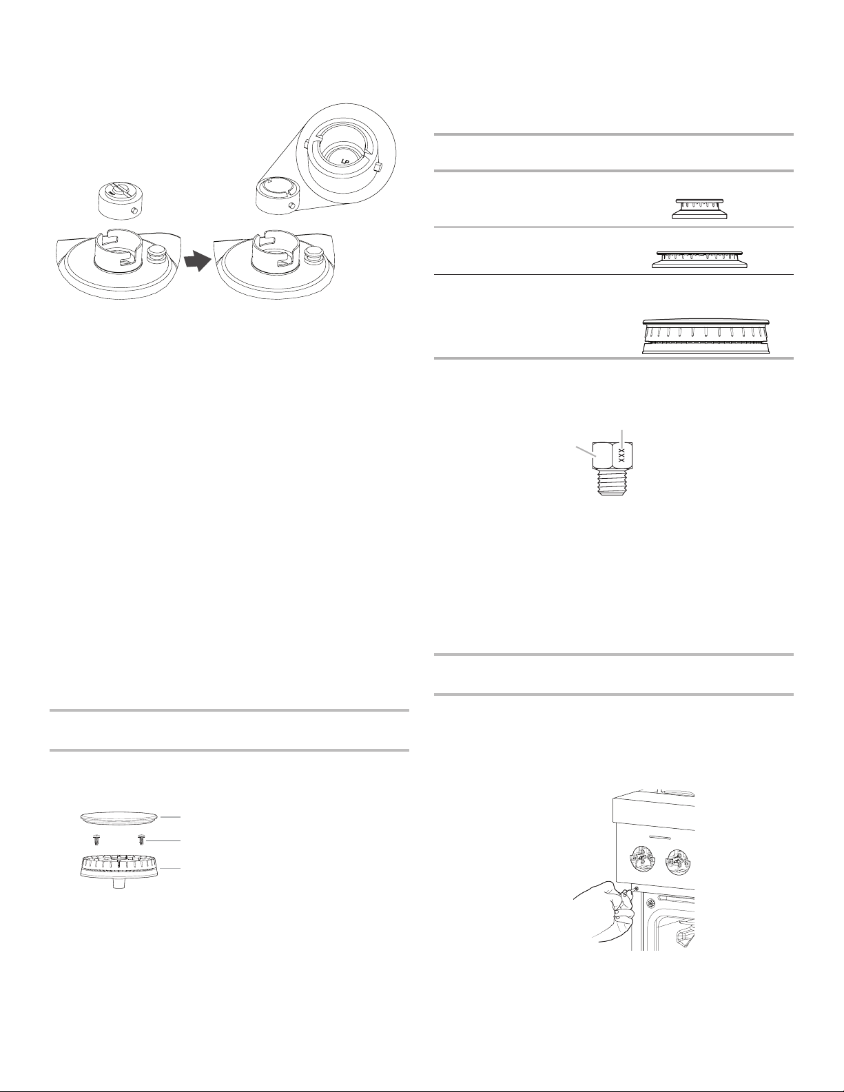
5. Turn over the gas pressure regulator cap, and reinstall on the
regulator so that the hollow end faces out and the letters
“LP” are visible.
6. Tighten the gas pressure regulator cap by using a large
at-blade screwdriver, turning the regulator cap clockwise.
7. Test the gas pressure regulator and gas supply line.
The regulator must be checked at a minimum 1" (2.5 cm)
water column above the set pressure. The inlet pressure to
the regulator should be as follows for operation and checking
the regulator setting:
Propane Gas:
Minimum pressure: 10" (25.4 cm) WCP
Maximum pressure: 14" (35.6 cm) WCP
Gas Supply Pressure Testing
Gas supply pressure for testing regulator must be at least
1" (2.5 cm) water column pressure above the manifold
pressure shown on the model/serial/rating plate.
Line pressure testing above 1/2 psi (3.5 kPa) gauge
(14" [35.6cm] WCP)
The range and its individual shut-off valve must be
disconnected from the gas supply piping system during
anypressure testing of that system at test pressures in
excess of 1/2 psi (3.5 kPa).
Line pressure testing at 1/2 psi (3.5 kPa) gauge
(14" [35.6cm]WCP) orlower
The range must be isolated from the gas supply piping
system by closing its individual manual shut-off valve during
any pressure testing of the gas supply piping system at test
pressures equal to or less than 1/2 psi (3.5 kPa).
To Convert Surface Burners from Natural Gas to
Propane
1. If the burner grates are installed, remove them.
2. Remove burner cap.
3. Remove the burner base by rst removing (2) T-20 screws.
Burner
A. Burner cap
B. Screws
C. Burner base
4. Apply masking tape to the end of a 7 mm nut driver to help
hold the gas orice spud in the nut driver while changing it.
Insert nut driver into the gas opening and press down onto
the gas orice spud and remove by turning the gas orice
spud counterclockwise and lifting out. Set gas orice spud
aside.
5. Replace with correct Propane gas orice spud. See the
“Propane Gas Orice Spud/Hood Chart”.
Use the following chart to nd the exact orice spud
placement.
Propane Gas Orice Spud/Hood Chart
Burner
Rating
Stamp Size Burner Style
4,000 BTUs 63 0.63 mm Small burner
12,000 BTUs 103 1.03 mm Medium burner
13,000 BTUs 99
50
0.99 mm
0.50 mm
Large burner – main
Larger burner – simmer
NOTE: Refer to serial tag for more information on burner ratings
and locations.
Burner orice spud
6. Place Natural gas orice in plastic parts bag for future use
and keep with package containing literature.
NOTE: There may be extra orices in your kit.
7. Replace the burner base and screws. Tighten screws only
until burner is snug to cooktop, do not over-tighten.
8. Replace burner cap.
9. Repeat steps 2 through 8 for the remaining burners.
Adjusting Simmer Low Setting on Surface Burners
for Propane
1. Unplug range or disconnect power.
2. Using the square bit screwdriver, remove the surface burner
control knobs and bezels (Oven control knobs and griddle
control knobs do not have to be removed).
3. Open the oven door and remove the two screws on each
side of the range that hold the control console in place.
NOTE: Make sure to leave the door open or the control
console will not rest in the side brackets properly once it is
attached.
A
B
A. Size stamp
B. Fuel type stamp (L or N)
A
C
B
Loading ...
Loading ...
Loading ...