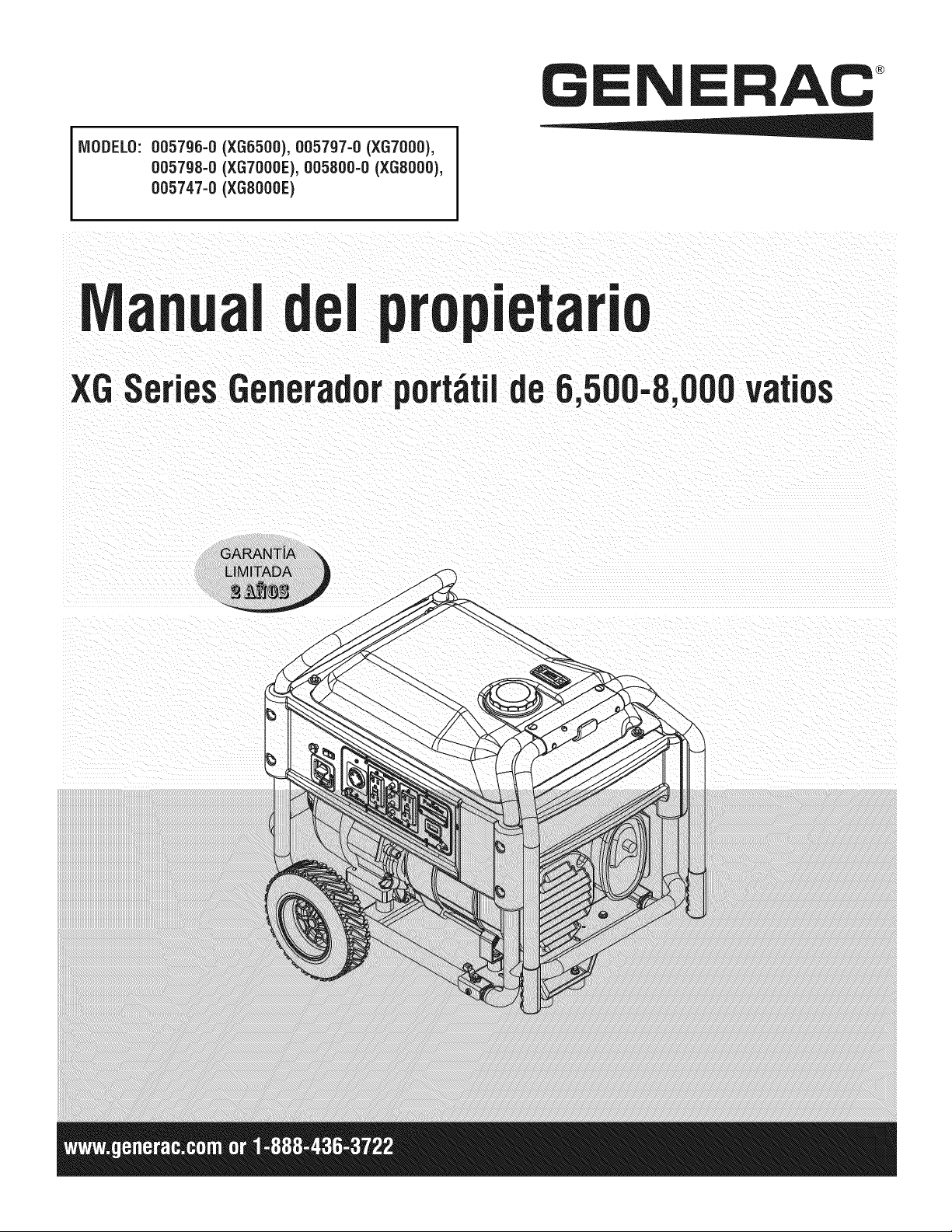
MODELS:
005796-0 (XG6500), 005797-0 (XG7000),
005798-0 (XG7OOOE),005800-0 (XGSO00),
005747-0 (XGS000E)
GENERAC _
0wnsr's
XGSeries6,500-8,
WattPorta e Generator
L M|TED
introduction.............................................................1
Readthis iVlanualThoroughly.................................1
Safety Rules...........................................................1
StandardsIndex.............................................................3
Generalinformation................................................4
1.1 Unpacking......................................................................4
1.1.1 Accessory Box ..................................................4
1.2 Assembly.......................................................................4
1.2.1 Assemblingthe Wheel Kit and FrameFoot..........4
Operation................................................................5
2.1 Know the Generator.......................................................5
2.1.1 Battery Connection(XG7000E& XG8000E).......6
2.2 Hourmeter......................................................................6
2.3 Cord Setsand ConnectionPlugs....................................6
2.3.1 120 VAC, 20 Amp, GFCIDuplexReceptacle.......6
2.3.2 120/240 VAC,30 Amp Receptacle.....................6
2.4 How to Use the Generator..............................................7
2.4.1 SystemGround..................................................7
2.4.2 Groundingthe Generator....................................7
2.4.3 Neutralto FrameGrounding...............................8
2.4.4 ConnectingElectricalLoads...............................8
2.5 Don't Overloadthe Generator..........................................8
2.6 WattageReferenceGuide...............................................8
2.7 BeforeStarting the Generator.........................................9
2.7.1 AddingEngineOil ..............................................9
2.7.2 AddingGasoline.................................................9
2.8 To Startthe Engine.......................................................10
2.8.1 Manual (Recoil)Starting ..................................10
2.8.2 Electric Starting (XG7000E& XG8000E)..........11
2.9 Stoppingthe Engine.....................................................11
2.10 Low Oil PressureShutdown System.............................11
2.10.1 Restarting........................................................11
2.11 Charginga Battery.......................................................11
Maintenance.........................................................11
3.1 MaintenanceSchedule.................................................11
3.2 ProductSpecifications..................................................11
3.2.1 GeneratorSpecifications..................................11
3.2.2 EngineSpecifications.......................................12
3.2.3 EmissionsInformation.....................................12
3.3 GeneralRecommendations...........................................12
3.3.1 GeneratorMaintenance....................................12
3.3.2 ToCleanthe Generator.....................................13
3.3.3 EngineMaintenance.........................................13
3.3.4 CheckingOil Level...........................................13
3.3.5 Changingthe Oiland Oil Filter..........................13
3.3.6 Replacingthe Spark Plug.................................13
3.4 ServiceAir Cleaner.......................................................13
3.5 CleanSparkArrestorScreen.........................................14
3.6 General........................................................................14
3.7 LongTerm Storage.......................................................14
3.8 OtherStorageTips.......................................................15
BatteryService .....................................................15
4.1 Battery Replacement(XG7000E& XG8000E)...............15
Troubleshooting....................................................16
5.1 TroubleshootingGuide..................................................16
Notes....................................................................17
Warranty...............................................................18
iNTRODUCTiON
Thankyou for purchasingthis model by GeneracPowerSystems,
Inc. This model is a compact, high performance, air-cooled,
engine driven generator designed to supply electrical power to
operate electrical loads where no utility power is available or in
place of utility dueto a power outage.
BEADTHiSMANUALTHOROUGHLY
If any portion of this manual is not understood, contact the
nearest Authorized Dealer for starting, operating and servicing
procedures.
The operator is responsible for proper and safe use of the
equipment. We strongly recommend that the operator read this
manualand thoroughlyunderstandall instructions beforeusingthe
equipment.We also stronglyrecommendinstructingother usersto
properlystart and operatethe unit. This preparesthem if they need
to operatethe equipment in an emergency.
The generatorcan operate safely,efficiently and reliably only if it
is properly located, operatedand maintained.Before operatingor
servicing the generator:
• Becomefamiliar with and strictly adhereto all local, state and
nationalcodes and regulations.
• Study all safety warnings in this manual and on the product
carefully.
• Becomefamiliar with this manual andthe unit beforeuse.
The manufacturercannot anticipateevery possible circumstance
that might involvea hazard.The warnings in this manual,and on
tags and decals affixedto the unit are, therefore,not all inclusive.
If using a procedure, work method or operatingtechniquethat the
manufacturerdoes not specifically recommend, ensure that it is
safe for others. Also make sure the procedure,work method or
operatingtechnique utilizeddoes not renderthe generatorunsafe.
THE INFORMATIONCONTAINEDHEREIN WAS BASED ON
MACHINESIN PRODUCTIONAT THE TIME OF PUBLICATION.
GENERACRESERVESTHERIGHTTO MODIFYTHIS MANUALAT
ANYTIME.
SAFETYRULES
Throughoutthis publication,and on tags and decals affixedto the
generator,DANGER,WARNING,CAUTIONand NOTEblocks are
used to alert personnelto special instructions about a particular
operation that may be hazardous if performed incorrectly or
carelessly. Observe them carefully. Their definitions are as
follows:
iNDICATESA HAZARDOUSSiTUATiONORACTIONWHICH,IF
NOTAVOIDED,WiLLRESULTiN DEATHORSERIOUSiNJURY.
Indicates a hazardoussituationor actionwhich,if not
avoided, couldresultin deathor seriousinjury.
_CAUTION!
Indicates a hazardoussituationor actionwhich,if not
avoided, couldresultin minoror moderateinjury.
NOTE:
Notescontainadditionalinformation importantto a procedure
and will be found within the regular text bodyof this manual.
These safety warnings cannot eliminate the hazards that they
indicate. Common sense and strict compliance with the special
instructions while performing the action or service are essentialto
preventingaccidents.
Four commonly used safety symbols accompany the DANGER,
WARNINGand CAUTIONblocks. The type of information each
indicates is as follows:
,_This symbol points out important safety
information that, if not followed, could
endanger personal safety and/or property of
others.
This symbol points out potential explosion
hazard.
This symbol points out potential fire hazard.
This symbol points out potential electrical
shock hazard.
GENERAL HAZARDS
• Neveroperatein an enclosedarea or indoors.
• For safety reasons, the manufacturer recommends that the
maintenanceof this equipmentis carried out by an Authorized
Dealer.Inspectthe generatorregularly,and contactthe nearest
AuthorizedDealerfor parts needing repairor replacement.
• Operategeneratoronly on levelsurfacesandwhereit will not be
exposedto excessivemoisture, dirt, dust or corrosive vapors.
• Keep hands, feet, clothing, etc., away from drive belts, fans,
and other moving parts. Neverremoveany fan guard or shield
while the unit is operating.
• Certain parts of the generator get extremely hot during
operation. Keep clear of the generator until it has cooled to
avoid severeburns.
• Do NOToperategeneratorinthe rain.
• Do not alter the construction of the generator or change
controls which might create an unsafe operatingcondition.
• Never start or stop the unit with electrical loads connected
to receptaclesAND with connected devices turned ON. Start
the engine and let it stabilize before connecting electrical
loads. Disconnect all electrical loads beforeshutting down the
generator.
• Do not insert objectsthrough unit's cooling slots.
• When working on this equipment, remain alert at all times.
Never work on the equipment when physically or mentally
fatigued.
• Neverusethegeneratororanyofitspartsasastep.Stepping
ontheunitcanstressandbreakparts,andmayresultin
dangerousoperatingconditionsfromleakingexhaustgases,
fuelleakage,oilleakage,etc.
• Onelectricstartmodels,disconnectthePOSITIVE(+) battery
cablefromtheenginestarterORtheNEGATIVE(-) battery
cablefromthebatteryterminal,whicheveris easier,before
transportingthegenerator.
NOTE:
Thisgenerator is equipped with a spark arrestor muffler. The
spark arrestor must be maintained in effective working order
by the owner/operator. In the State of California, a spark
arrestoris requiredby law (Section4442 of the California
PublicResources Code). Other states may have similar laws.
Federal laws apply on federal lands.
EXHAUST & LOCATIONHAZARDS
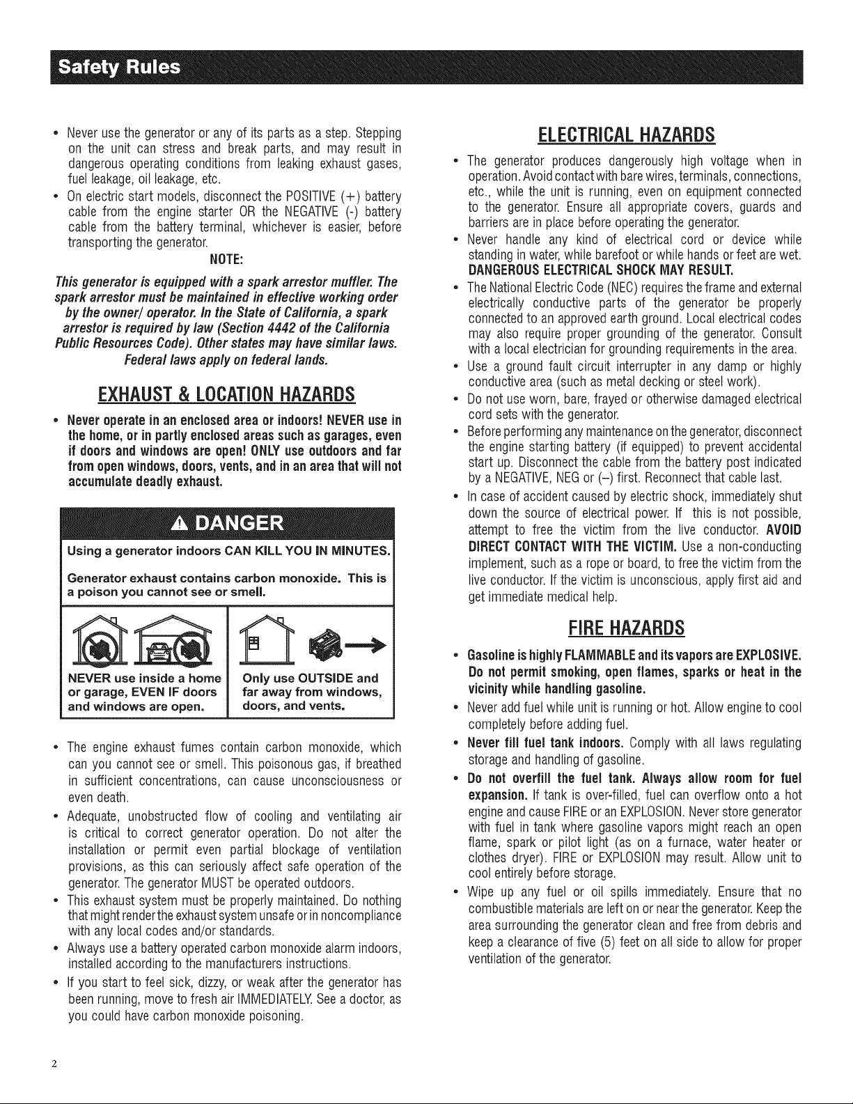
• Never operate in an enclosed area or indoors!NEVERuse in
the home,or in partly enclosed areas suchas garages, even
if doors and windowsare open! ONLYuse outdoors and far
fromopen windows,doors, vents,and in an area thatwill not
accumulatedeadly exhaust.
Using a generator indoors CAN KiLL YOU iN MINUTES.
Generator exhaust contains carbon monoxide. This is
a poison you cannot see or smell,
NEVER use inside a home
or garage, EVEN IF doors
and windows are open.
Only use OUTSIDE and
far away from windows,
doors, and vents.
• The engine exhaust fumes contain carbon monoxide, which
can you cannot see or smell. This poisonous gas, if breathed
in sufficient concentrations, can cause unconsciousness or
evendeath.
• Adequate, unobstructed flow of cooling and ventilating air
is critical to correct generator operation. Do not alter the
installation or permit even partial blockage of ventilation
provisions, as this can seriously affect safe operation of the
generator.The generatorMUST be operatedoutdoors.
• This exhaust system must be properly maintained.Do nothing
that mightrenderthe exhaustsystemunsafeor innoncompliance
with any local codes and/or standards.
• Always use a battery operatedcarbon monoxidealarm indoors,
installedaccording to the manufacturersinstructions.
• If you start to feet sick, dizzy, or weak after the generator has
beenrunning,moveto fresh air IMMEDIATELYSee a doctor,as
you could have carbon monoxidepoisoning.
ELECTRICALHAZARDS
• The generator produces dangerously high voltage when in
operation.Avoidcontactwith barewires,terminals,connections,
etc., while the unit is running, even on equipmentconnected
to the generator. Ensure all appropriate covers, guards and
barriers arein place beforeoperatingthe generator.
• Never handle any kind of electrical cord or device while
standingin water,while barefoot orwhile handsor feet arewet.
DANGEROUSELECTRICALSHOCKMAY RESULT.
• TheNationalElectricCode (NEC)requirestheframe and external
electrically conductive parts of the generator be properly
connectedto an approvedearth ground. Local electricalcodes
may also require proper grounding of the generator.Consult
with a local electricianfor groundingrequirementsin the area.
• Use a ground fault circuit interrupter in any damp or highly
conductivearea (such as metal decking or steelwork).
• Do not useworn, bare,frayed or otherwise damagedelectrical
cord sets with the generator.
• Beforeperforminganymaintenanceon thegenerator,disconnect
the enginestarting battery (if equipped) to prevent accidental
start up. Disconnectthe cable from the battery post indicated
by a NEGATIVE,NEGor (-) first. Reconnectthat cable last.
• In caseof accident caused by electric shock, immediately shut
down the source of electrical power. If this is not possible,
attempt to free the victim from the live conductor. AVOID
DIRECTCONTACTWITH THEVICTIM, Use a non-conducting
implement,such as a rope or board,to free the victim from the
live conductor.If the victim is unconscious, apply first aid and
get immediatemedical help.
FIREHAZARDS
• GasolineishighlyFLAMMABLEand itsvaporsare EXPLOSIVE.
Do not permit smoking,open flames, sparks or heat in the
vicinitywhile handlinggasoline.
• Neveraddfuel while unit is running or hot. Allow engineto cool
completelybefore addingfuel.
• Never fill fuel tank indoors, Comply with all laws regulating
storageand handlingof gasoline.
• Do not overfill the fuel tank. Always allow room for fuel
expansion. If tank is over=filled,fuel can overflow onto a hot
engineandcause FIREor an EXPLOSION.Neverstoregenerator
with fuel in tank where gasoline vapors might reach an open
flame, spark or pilot light (as on a furnace, water heater or
clothes dryer). FIREor EXPLOSIONmay result. Allow unit to
cool entirelybefore storage.
• Wipe up any fuel or oil spills immediately. Ensure that no
combustiblematerialsare left on or nearthe generator.Keepthe
areasurroundingthe generatorclean andfree from debris and
keep a clearance of five (5) feet on all side to allow for proper
ventilationof the generator.
* Do not insert objects through unit's cooling slots.
* Do not operate the generator if connected electrical devices
overheat,if electricaloutputis lost, if engineor generatorsparks
or if flames or smoke are observedwhile unit is running.
* Keepa fire extinguishernearthe generatorat all times.
STAtVDARDS/#DEX
In the absence of pertinent standards, codes, regulations and
laws, the published information listed below may be used as a
guidelinefor operation of this equipment. Always reference the
latest revisionavailablefor the standardslisted.
1. NFPANo. 70, NFPAHANDBOOKOF NATIONALELECTRIC
CODE.
2. Article X, NATIONALBUILDINGCODE, available from the
American InsuranceAssociation, 85 John Street, NewYork,
N.Y.10038.
3. AGRICULTURALWIRINGHANDBOOK,availablefrom the Food
and Energy Council, 909 University Avenue, Columbia, Me
65201.
4. ASAE EP-3634, INSTALLATIONAND MAINTENANCEOF
FARMSTANDBYELECTRICALSYSTEMS,availablefrom the
AmericanSociety of AgriculturalEngineers,2950 Niles Road,
St. Joseph, MI 49085.
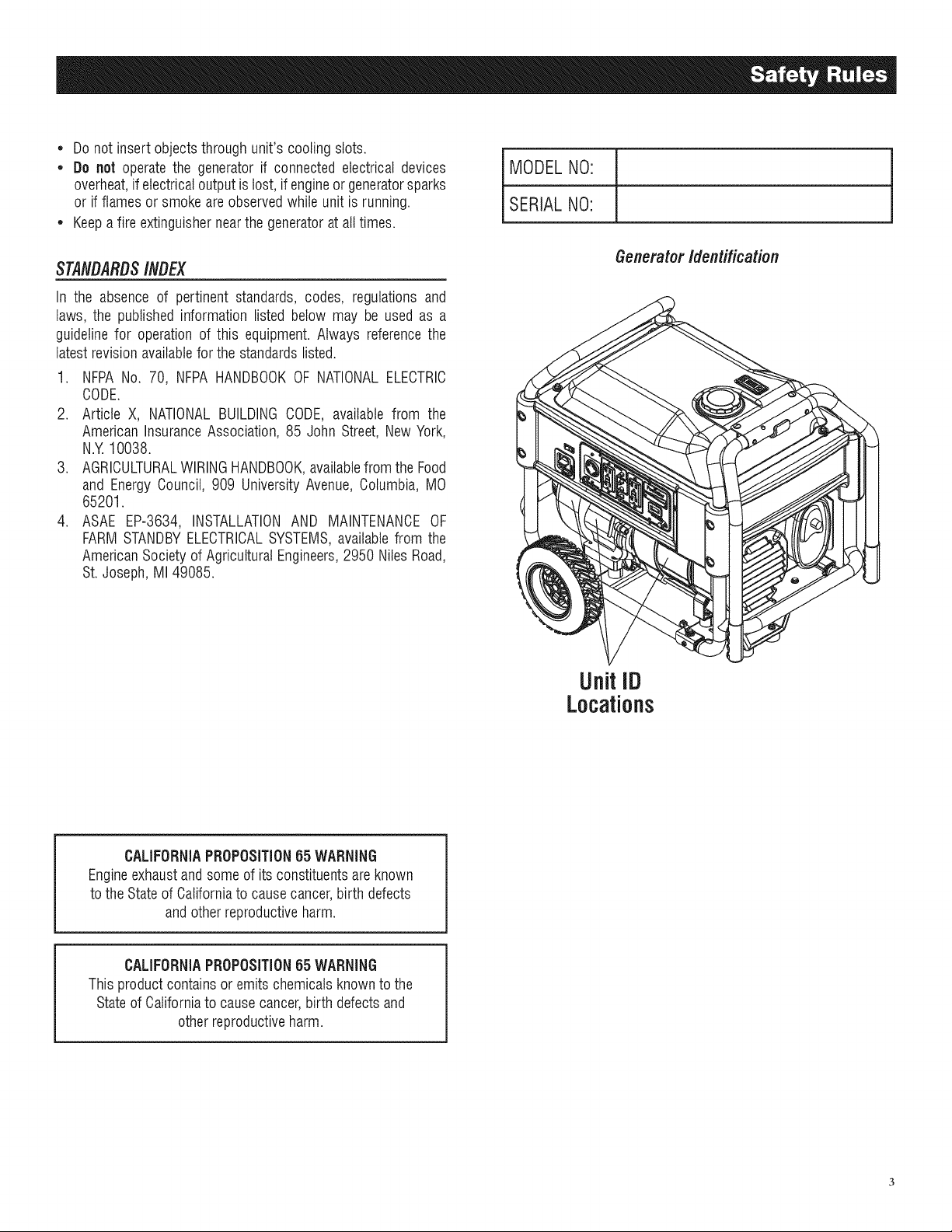
MODELNO:
SERIALNO:
Generator Identification
Unit ID
Locations
CALIFORNIAPROPOSiTiON65 WARNING
Engineexhaustand someof its constituentsareknown
to the Stateof Californiato causecancer,birth defects
and otherreproductiveharm.
CALIFORNIAPROPOSITION65 WARNING
Thisproduct contains or emits chemicals knownto the
Stateof Californiato cause cancer,birth defects and
other reproductiveharm.
1.1 UNPACKING
• Removeall packagingmaterial.
• Removeseparateaccessory box.
• Removecarton off the generator.
1.1.1 ACCESSORYBOX
Checkall contents(Figure1). If any parts aremissing or damaged
locatean authorizeddealerat 1-888-775-6937.
Contentsinclude:
• 2-Axle Pins • Oil Filter
• 2- Wheel Spacers • Air Filter
• 2- Hair Pins • Spark Plug
• 2- Wheels • Spark PlugWrench
• 1 - FrameFoot • ShopTowel
• 2 - FrameBolts • 2 - FrameWashers
• 2-Vibration Mounts • Oil Funnel
• 4 - FlangeNuts 12 Volt Adaptor Plug Charger
• 2 - 1 Quart SAE 30 Oil Bottles
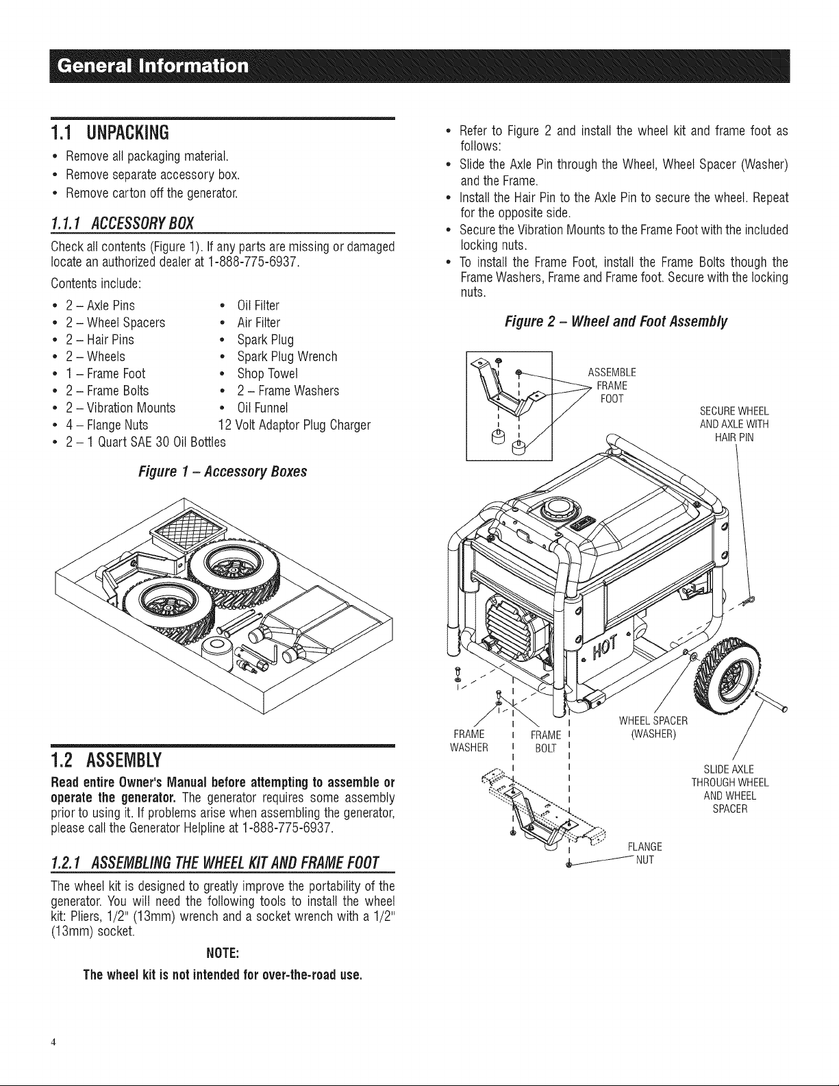
Figure 1 - Accessory Boxes
• Referto Figure 2 and install the wheel kit and frame foot as
follows:
• Slidethe Axle Pin through the Wheel,Wheel Spacer (Washer)
andthe Frame.
• Install the Hair Pinto the Axle Pin to securethe wheel. Repeat
for the oppositeside.
• Securethe VibrationMountsto the FrameFootwith the included
locking nuts.
• To install the Frame Foot, install the Frame Bolts though the
FrameWashers,Frameand Framefoot. Securewith the locking
nuts.
Figure 2 - Wheel and Foot Assembly
FOOT
SECUREWHEEL
AND AXLEWITH
HAIRPIN
1.2 ASSEMBLY
Read entire Owner's Manual before attemptingto assemble or
operate the generator. The generator requires some assembly
prior to using it. If problems arise when assemblingthe generator,
pleasecall the GeneratorHelplineat 1-888-775-6937.
1.2.1 ASSEMBLINGTIlE WHEELKITANDFRAMEFOOT
The wheel kit is designedto greatly improvethe portability of the
generator.You will need the following tools to install the wheel
kit: Pliers,1/2" (13mm) wrench and a socket wrench with a 1/2"
(13mm) socket.
NOTE:
The wheel kit is not intendedfor over-the-road use.
FRAME
WASHER
FRAME
BOLT
WHEELSPACER
(WASHER)
SLIDEAXLE
THROUGHWHEEL
AND WHEEL
SPACER
2.1 KNOWTHEGENERATOR
Read the entire Owner's Manual and Safety Rules before
operatingthisgenerator.
Compare the generator to Figures 3 through 6 to become
familiarizedwith the locationsof various controls andadjustments.
Savethis manualfor future reference.
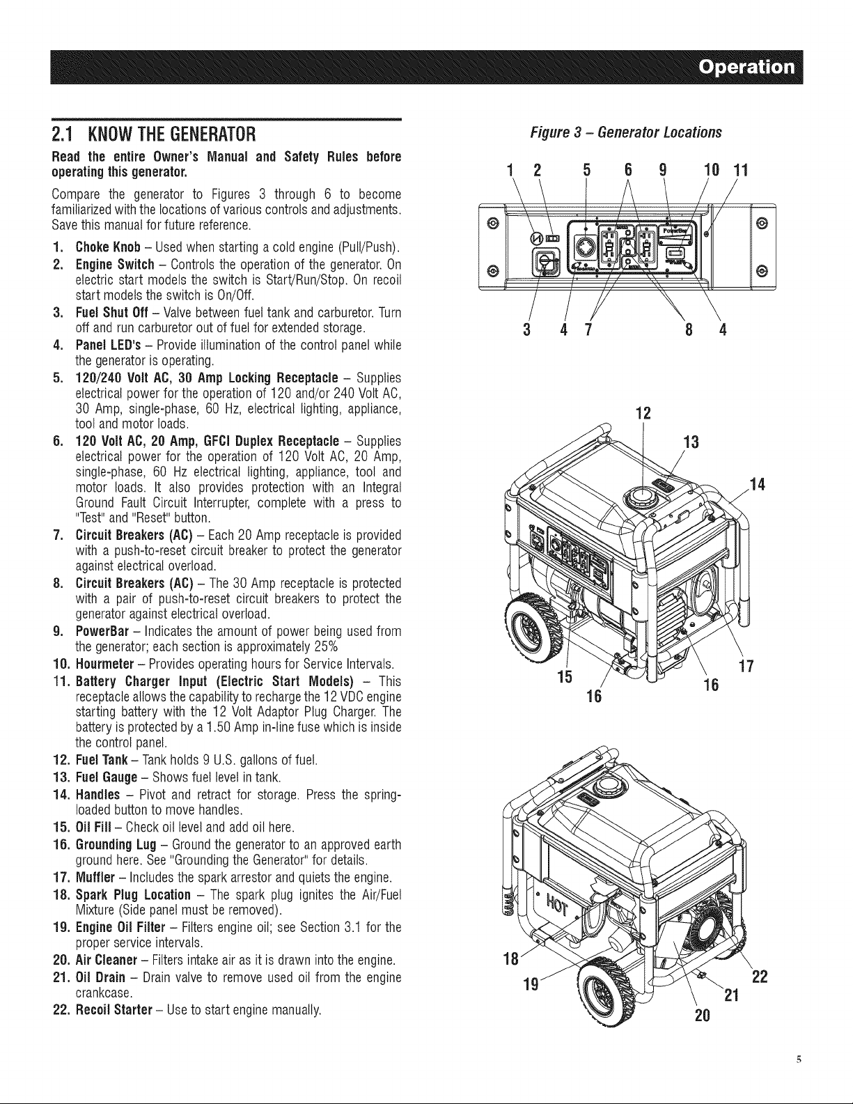
1. ChokeKnob- Usedwhen starting a cold engine (Pull/Push).
2. EngineSwitch - Controls the operation of the generator.On
electric start models the switch is Start/Run/Stop.On recoil
start modelsthe switch is On/Off.
3. Fuel Shut Off - Valvebetweenfuel tank and carburetor.Turn
off and run carburetorout of fuel for extendedstorage.
4. PanelLED's - Provideilluminationof the control panelwhile
the generatoris operating.
5. 120/240 Volt AC, 30 Amp LockingReceptacle- Supplies
electrical power for the operation of 120 and/or 240 Volt AC,
30 Amp, single-phase, 60 Hz, electrical lighting, appliance,
tool andmotor loads.
5. 120 Volt AC, 20 Amp, GFCiDuplex Receptacle- Supplies
electrical power for the operation of 120 Volt AC, 20 Amp,
single-phase, 60 Hz electrical lighting, appliance, tool and
motor loads. It also provides protection with an Integral
Ground Fault Circuit Interrupter, complete with a press to
"Test"and "Reset"button.
7. Circuit Breakers (AC) - Each20 Amp receptacleis provided
with a push-to-reset circuit breakerto protect the generator
againstelectricaloverload.
8. Circuit Breakers (AC) - The 30 Amp receptacleis protected
with a pair of push-to-reset circuit breakers to protect the
generatoragainst electricaloverload.
g. PowerBar - Indicatesthe amount of power being used from
the generator;each section is approximately25%
10. Hourmeter - Providesoperatinghours for Service Intervals.
11. Battery Charger input (Electric Start Models) - This
receptacleallowsthe capabilityto rechargethe 12 VDCengine
starting battery with the 12 Volt Adaptor Plug Charger.The
battery is protectedby a 1.50 Amp in-linefuse which is inside
the control panel.
12. FuelTank- Tankholds 9 U.S. gallons of fuel.
13. FuelGauge- Showsfuel levelin tank.
14. Handles - Pivot and retract for storage. Press the spring-
loadedbutton to move handles.
15. Oil Fill- Checkoil level andadd oil here.
18. GroundingLug- Groundthe generatorto an approvedearth
groundhere. See "Groundingthe Generator"for details.
17. Muffler- Includesthe spark arrestor and quietsthe engine.
18. Spark Plug Location - The spark plug ignites the Air/Fuel
Mixture (Sidepanel must be removed).
lg. Engine Oil Filter - Filtersengineoil; see Section 3.1 for the
properservice intervals.
20. Air Cleaner - Filtersintakeair as it is drawn into the engine.
21. Oil Drain- Drain valve to remove used oil from the engine
crankcase.
22. Recoil Starter - Useto start enginemanually.
Figure 3 - GeneratorLocations
2 5 8 9 10
3 4 7 8 4
12
13
15
16
2O
11
@
@
17
22
2.1.1 BATTERYCONNECtiONfXG7OOOE& XG8OOOE)
NOTE:
The battery shippedwiththe generator hasbeen fully charged.
A battery may lose someof its chargewhennot in use for
prolongedperiodsof time. If the battery is unable to crank
the engine, plugin the 12V chargerincludedin the accessory
box (see the Chargingthe Battery section).RUNNINGTHE
GENERATORDOESNOTCHARGETHE BATTERY.
The positive battery wire was deliberately left detached for
shipping. To operatethe unit, attach this wire to the terminal on
the starter motor as shown. Do not overtighten. Slidethe attached
rubber boot over the starter terminal. See Figure4.
Figure4 - Battery Connection
/
/ L_'! / //// /fi BATTERYCABLE_
2.2 HOUBMETEB
The Hourmeter tracks hours of operation for scheduled
maintenance:
Therewilt be a one time break in "CHGOIL" messagethat flashes
with the elapsedtime in hours and tenths after the first 30 hours
of operation.
This messagewill actually begin flashing at 29 hours and disable
itself at 31 hours providing a two hour window to perform the
service.
Therewill be a subsequent"CHGOIL" messageevery 100 hours.
The message will flash one hour before and one hour after each
100 hour interval, again providing a two hour window to perform
service.
Every200 hours the "SVC"icon on the lower left hand corner of
the display will flash. The messagewill flash one hourbefore and
onehour after each 200 hourintervalprovidinga two hourwindow
to perform service.
Whenthe hour meter is in the FlashAlert mode, the maintenance
message will always alternate with elapsed time in hours and
tenths. The hours wilt flash four times, then alternate with the
maintenancemessagefour times until the meter resets itself.
* 100 hours - CHGOIL-- Oil ChangeInterval(Every100 hrs)
* 200 hours - SVC-- Air Filter Interval (Every200 hrs)
2.3 CORD SETSAND CONNECTIONPLUGS
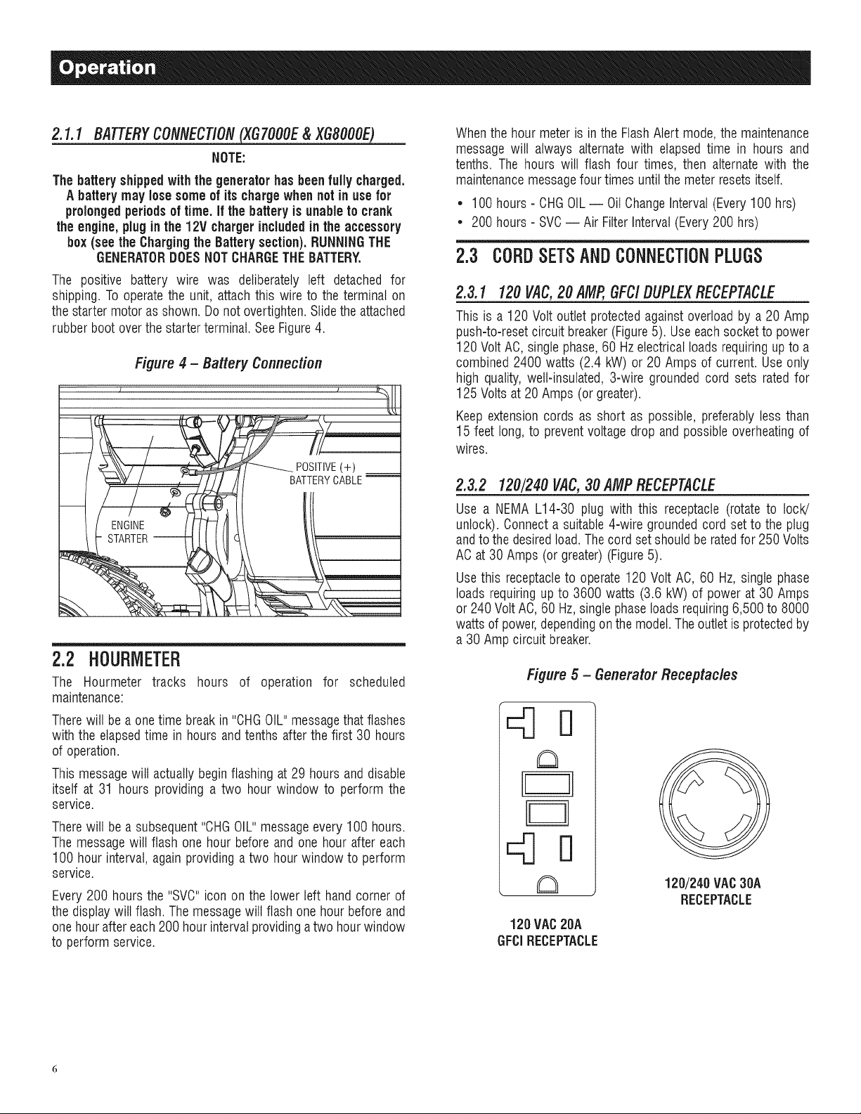
2.3.1 120 VAC,20 AMP,GFC/DUPLEXRECEPTACLE
This is a 120 Volt outlet protectedagainst overloadby a 20 Amp
push-to-resetcircuit breaker (Figure5). Useeach socket to power
120 Volt AC, single phase,60 Hzelectrical loads requiring upto a
combined 2400 watts (2.4 kW) or 20 Amps of current. Use only
high quality, well-insulated, 3-wire grounded cord sets rated for
125 Volts at 20 Amps (or greater).
Keep extensioncords as short as possible, preferably less than
15 feet long, to preventvoltage drop and possible overheatingof
wires.
2.3.2 120/240VAC,30 AMP RECEPTACLE
Use a NEMA L14-30 plug with this receptacle (rotate to lock!
unlock). Connecta suitable 4-wire grounded cord set to the plug
andto the desiredtoad.The cord set should be ratedfor 250 Volts
AC at 30 Amps (or greater) (Figure5).
Use this receptacleto operate 120 Volt AC, 60 Hz, single phase
loads requiringup to 3600 watts (3.6 kW) of power at 30 Amps
or 240 Volt AC,60 Hz, single phaseloads requiring6,500 to 8000
watts of power,dependingon the model. The outletis protectedby
a 30 Amp circuit breaker.
Figure 5 - GeneratorReceptacles
Kin
, a
120 VAC20A
GFCIRECEPTACLE
120/240 VAC30A
RECEPTACLE
2.4 HOW TO USETHEGENERATOR
If there are any problems operatingthe generator,pleasecall the
generatorhelplineat 1-888-436-3722.
,l_ Never operate in an enclosed area or indoors!
NEVER use in the home, or in partly enclosed
areas such as garages, even if doors and
windows are open! ONLY use outdoors and far
from open windows, doors, vents, and in an
area that will not accumulate deadly exhaust.
,l_The engine exhaust fumes contain carbon
monoxide, which can you cannot see or smell.
This poisonous gas, if breathed insufficient
concentrations, can cause unconsciousness or
even death.
Adequate, unobstructed flow of cooling and
ventilating air is critical to correct generator
operation. Do not alter the installation or permit
even partial blockage of ventilation provisions,
as this can seriously affect safe operation
of the generator. The generator MUST be
operated outdoors.
,l_This exhaust system must be properly
maintained. Do nothing that might render the
exhaust system unsafe or in noncompliance
with any local codes and/or standards.
,l_The manufacturer recommends installing
a battery operated carbon monoxide alarm
indoors, according to the manufacturers
instructions.
Using a generator indoors CAN KILL YOU IN MINUTES.
Generator exhaust contains carbon monoxide. This is
a poison you cannot see or smell.
NEVER use inside a home
or garage, EVEN iF doors
and windows are open,
Only use OUTSIDE and
far away from windows,
doors, and vents.
2.4.1 SYSTEMGROUND
The generator has a system groundthat connectsthe generator
frame components to the ground terminals on the AC output
receptacles. The system groundis bonded to the AC neutralwire
in the generatorcontrol panelvia a jumper wire.
SpecialRequirements
There may be Federalor State Occupational Safety and Health
Administration(OSHA)regulations,local codes, or ordinancesthat
apply to the intendeduse of the generator.
Please consult a qualified electrician, electrical inspector, or the
local agencyhavingjurisdiction:
* In some areas, generators are requiredto be registered with
local utility companies.
* If the generator is used at a construction site, there may be
additionalregulationswhich must be observed.
Connectingto a Building'sElectricalSystem
Connectionsfor standby power to a building's electrical system
must be made by a qualified electrician. The connection must
isolatethe generatorpower from utility power or other alternative
power sources and must comply with all applicable laws and
electricalcodes.
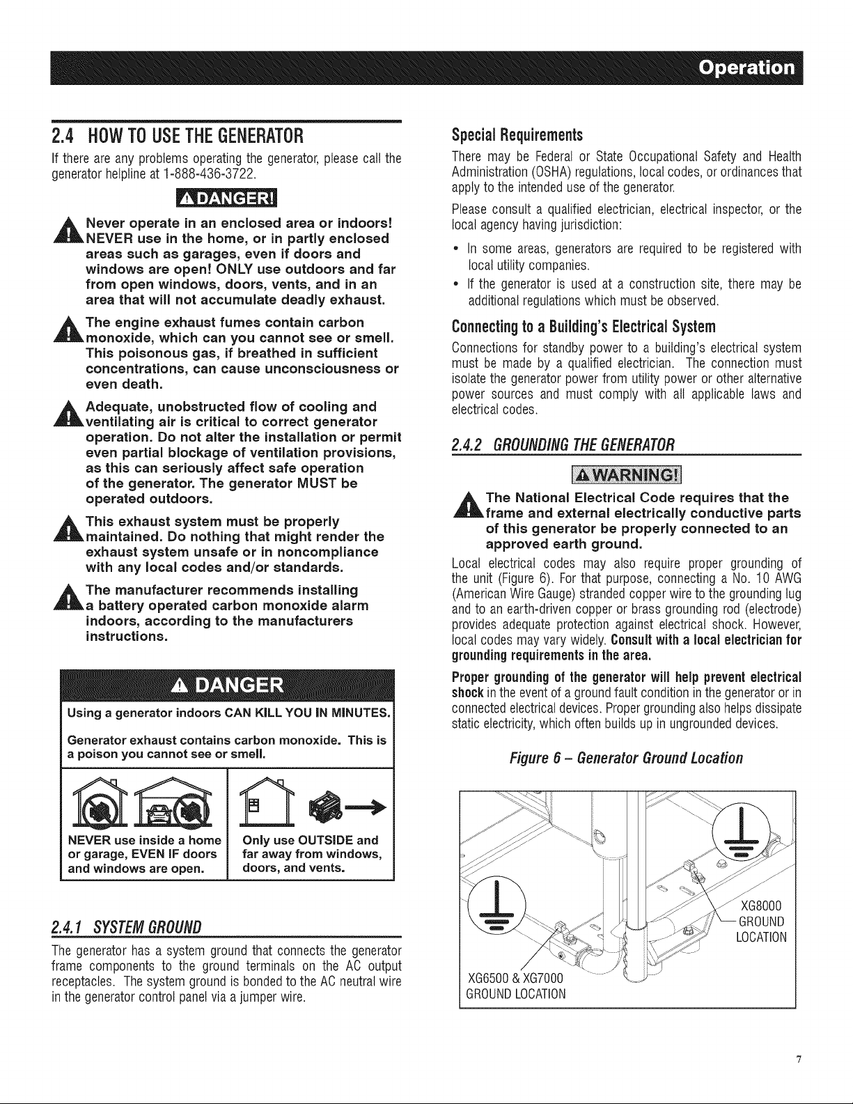
2.4.2 GROUND/NG TIlE GENERATOR
The National Electrical Code requires that the
frame and external electrically conductive parts
of this generator be properly connected to an
approved earth ground.
Local electrical codes may also require proper grounding of
the unit (Figure 6). Forthat purpose, connecting a No. 10 AWG
(AmericanWire Gauge)strandedcopper wire to the grounding lug
and to an earth=drivencopper or brass grounding rod (electrode)
provides adequate protection against electrical shock. However,
local codes may vary widely. Consultwith a local electricianfor
grounding requirements in the area.
Proper groundingof the generatorwill help preventelectrical
shockin the event of a groundfault condition inthe generatoror in
connectedelectricaldevices.Propergroundingalso helps dissipate
static electricity,which often builds up in ungroundeddevices.
Figure 6 - GeneratorGroundLocation
LOCATION
XG6500& XG7000
GROUNDLOCATION
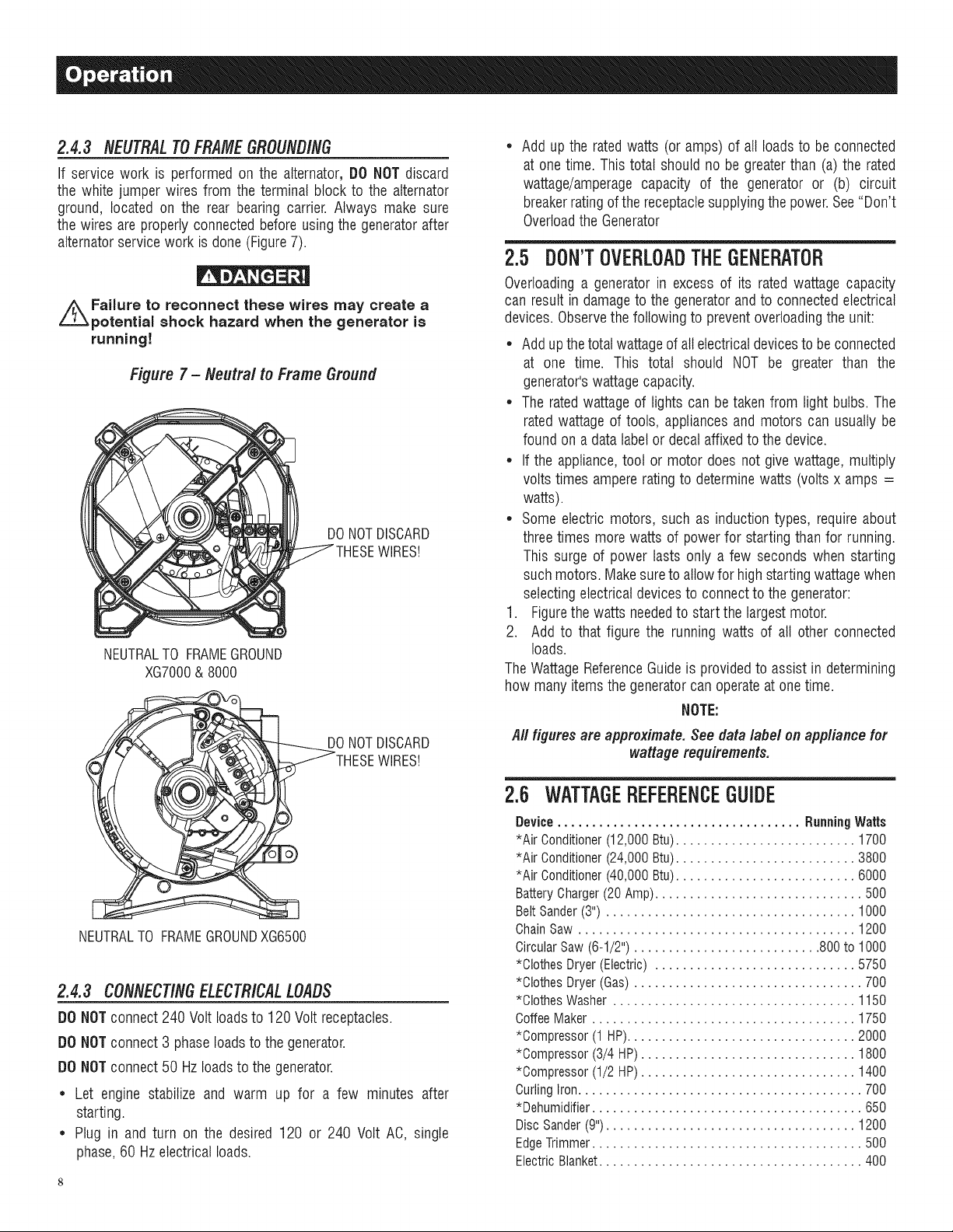
2.4.3 NEUTRAL70 FRAMEGROUNDING
If service work is performed on the alternator, DO NOT discard
the white jumper wires from the terminal block to the alternator
ground, located on the rear bearing carrier. Always make sure
the wires are properly connected before using the generatorafter
alternatorservice work is done (Figure7).
Failure to reconnect these wires may create a
potential shock hazard when the generator is
running!
Figure 7 - Neutral to Frame Ground
NEUTRALTO FRAMEGROUND
XG7000& 8000
DONOTDISCARD
WIREST
DONOTDISCARD
3EWIREST
NEUTRALTO FRAMEGROUNDXG6500
2.4.3 CONNECT/NGELECTR/CALLOADS
DO NOTconnect 240 Volt loadsto 120 Volt receptacles.
DO NOTconnect 3 phaseloads to the generator.
DO NOTconnect 50 Hzloads to the generator.
* Let engine stabilize and warm up for a few minutes after
starting.
* Plug in and turn on the desired 120 or 240 Volt AC, single
phase,60 Hz electrical loads.
Add up the ratedwatts (or amps) of all loadsto be connected
at one time. This total should no be greaterthan (a) the rated
wattage/amperage capacity of the generator or (b) circuit
breakerrating of the receptaclesupplyingthe power.See "Don't
Overloadthe Generator
2.5 DON'TOVERLOADTHEGENERATOR
Overloadinga generator in excess of its rated wattage capacity
can result in damageto the generatorandto connectedelectrical
devices.Observethe following to preventoverloadingthe unit:
* Addup the total wattageof all electricaldevicesto be connected
at one time. This total should NOT be greater than the
generator'swattage capacity.
* The ratedwattage of lights can be taken from light bulbs. The
rated wattage of tools, appliances and motors can usually be
found on a data label or decal affixedto the device.
* If the appliance,tool or motor does not give wattage,multiply
volts times ampererating to determinewatts (volts x amps =
watts).
* Some electric motors, such as induction types, require about
threetimes more watts of power for starting than for running.
This surge of power lasts only a few seconds when starting
suchmotors. Makesureto allowfor high startingwattagewhen
selectingelectrical devicesto connect to the generator:
1. Figurethe watts neededto start the largestmotor.
2. Add to that figure the running watts of all other connected
loads.
The WattageReferenceGuide is providedto assist in determining
how many items the generatorcan operateat onetime.
NOTE:
All figuresare approximate.See data label on appliancefor
wattagerequirements.
2.6 WATTAGEREFERENCEGUIDE
Device................................... RunningWatts
*Air Conditioner(12,000Btu).......................... 1700
*Air Conditioner(24,000Btu).......................... 3800
*Air Conditioner(40,000Btu).......................... 6000
BatteryCharger(20Amp).............................. 500
BeltSander(3") .................................... 1000
ChainSaw........................................ 1200
CircularSaw(6-1/2")........................... 800to 1000
*ClothesDryer(Electric)............................. 5750
*ClothesDryer(Gas)................................. 700
*ClothesWasher................................... 1150
CoffeeMaker...................................... 1750
*Compressor(1 HP)................................. 2000
*Compressor(3/4 HP)............................... 1800
*Compressor(1/2 HP)............................... 1400
CurlingIron......................................... 700
*Dehumidifier....................................... 650
DiscSander(9").................................... 1200
EdgeTrimmer....................................... 500
ElectricBlanket...................................... 400
Electric Nail Gun.................................... 1200
Electric Range(per element)........................... 1500
Electric Skillet...................................... 1250
*Freezer ............................................ 700
*Furnace Fan (3/5 HP) ................................ 875
*Garage Door Opener............................ 500 to 750
Hair Dryer......................................... 1200
Hand Drill .................................... 250 to 1100
HedgeTrimmer...................................... 450
Impact Wrench...................................... 500
Iron.............................................. 1200
*Jet Pump ......................................... 800
Lawn Mower....................................... 1200
Light Bulb.......................................... 1O0
Microwave Oven............................... 700 to 1000
*Milk Cooler....................................... 1100
Oil Burner on Furnace................................. 300
Oil FiredSpace Heater (140,000 Btu) ..................... 400
Oil FiredSpace Heater (85,000 Btu) ...................... 225
Oil FiredSpace Heater (30,000 Btu) ...................... 150
*Paint Sprayer,Airless (1/3 HP) ......................... 600
PaintSprayer,Airless (handheld)......................... 150
Radio ......................................... 50 to 200
*Refrigerator........................................ 700
Slow Cooker........................................ 200
*Submersible Pump (1-1/2 HP) ........................ 2800
*Submersible Pump (1 HP) ........................... 2000
*Submersible Pump (1/2 HP).......................... 1500
*Sump Pump ................................. 800 to 1050
*Table Saw (10") ............................. 1750 to 2000
Television..................................... 200 to 500
Toaster..................................... 1000 to 1650
WeedTrimmer ...................................... 500
* Allow 3 times the listed watts for starting these devices.
2.7 BEFORESTARTINGTHEGENERATOR
Prior to operating the generator, engine oil and gasoline will need
to be added, as follows:
2,7,1 AD#/NGEflG/NEO/L
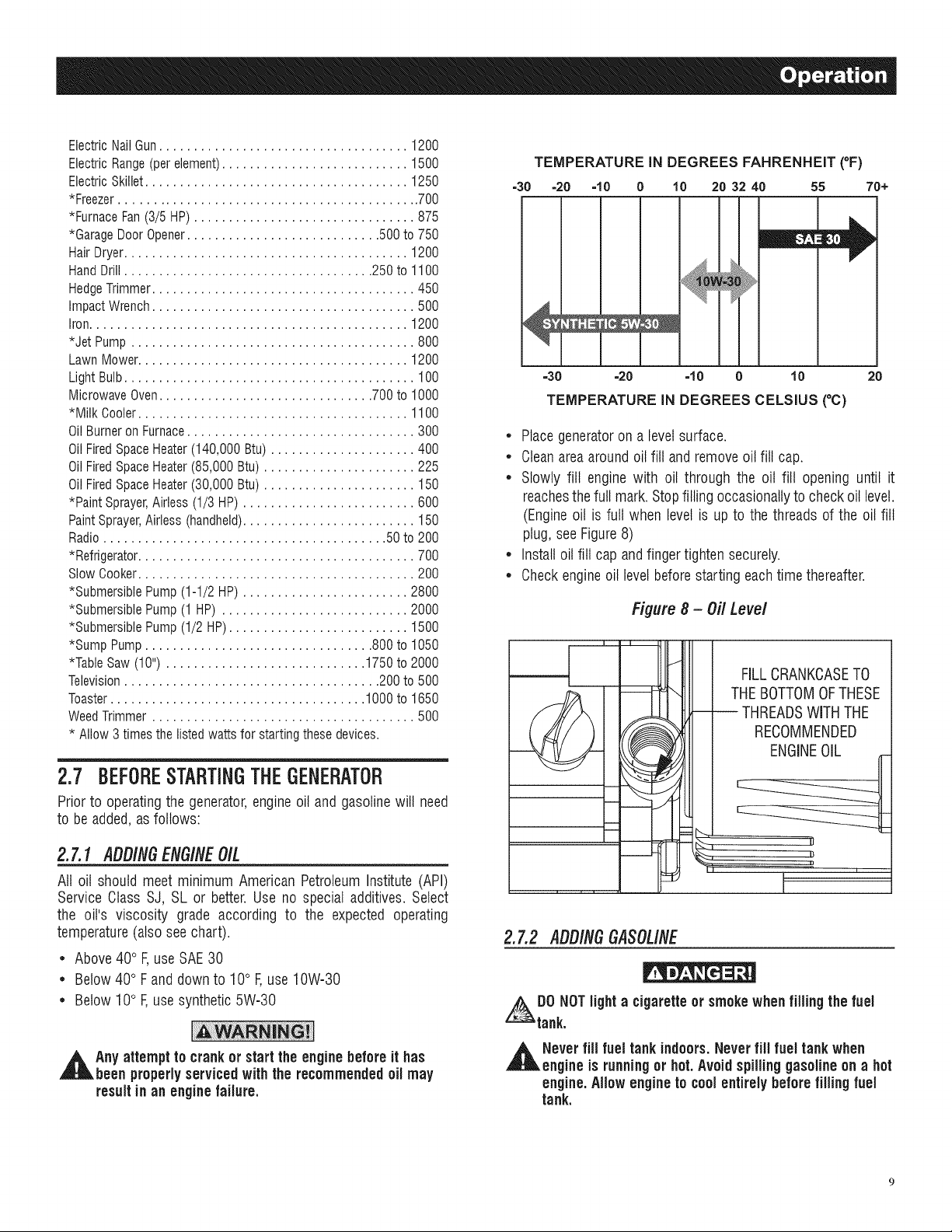
All oil should meet minimum American Petroleum Institute (API)
Service Class SJ, SL or better. Use no special additives. Select
the oil's viscosity grade according to the expected operating
temperature(also see chart).
• Above40° F,use SAE30
• Below 40° F and down to 10° F,use 10W-30
• Below 10° F,use synthetic 5W-30
,_Any attempt to crankor start the enginebeforeit has
been properlyserviced with the recommended oil may
resultin an enginefailure.
TEMPERATURE IN DEGREES FAHRENHEIT (°F)
=30 =20 ='tO 0 10 20 32 40 55 70+
||||
=30 =20 =10 0 10 20
TEMPERATURE IN DEGREES CELSIUS (°C)
• Place generatoron a levelsurface.
• Cleanarea aroundoil fill andremoveoil fill cap.
• Slowly fill engine with oil through the oil fill opening until it
reachesthe full mark. Stopfilling occasionallyto check oil level.
(Engineoil is full when level is up to the threads of the oil fill
plug, see Figure8)
• Install oil fill cap and finger tighten securely.
• Checkengine oil levelbefore starting eachtime thereafter.
Figure 8 - Off Level
L
--J
FILLCRANKCASETO
THE BOTTOMOFTHESE
-- THREADSWiTH THE
RECOMMENDED
ENGINEOIL
II
I
2.7,2 ADD/NGGASOLINE
ADO NOTlighta cigaretteor smoke when filling the fuel
tank.
,_ Neverfiil fuel tankindoors.Never fiil fuel tank when
engineis running or hot.Avoid spillinggasoline on a hot
engine.Allow engineto coolentirelybeforefilling fuel
tank.
Donot overfill the fuel tank.Alwaysleave roomfor fuel
expansion,if the fuel tank is overfilled,fuel can overflow
onto a hot engine and causeFiRE or EXPLOSION.Wipe
up any spilledfuel immediately.
• Use regular UNLEADEDgasolinewith the generatorengine. Do
not use premiumgasoline. Do not mix oil with gasoline.
• Do not use gasoline with more than 10% alcohol such as E85
or Methanol.
• Cleanarea aroundfuel fill cap, removecap.
• Slowly add unleadedregulargasolineto fuel tank. Fillto bottom
of screenfilter. Be carefulnot to overfill (Figure9).
• Installfuel cap and wipe up any spilled gasoline.
Figure g- Fuel Fill Level
DO NOTFILL
AB( LIP!
IMPORTANT:It is important to prevent gum depositsfrom forming
in fuel system parts such as the carburetor, fuel hose or tank
during storage. Alcohol-blended fuels (called gasohol, ethanol
or methanol)can attract moisture, which leads to separationand
formation of acids during storage.Acidic gas can damagethe fuel
system of an enginewhile in storage. To avoid engine problems,
the fuel system should be emptiedbefore storage of 30 days or
longer.See the "Storage"section. Neveruse engine or carburetor
cleaner products in the fuel tank as permanent damage may
occur.
2.8 TOSTARTTHEENGINE
Never start or stopengine withelectricaldevices pluggedinto
the receptacles ANDdevices turnedon.
• Unplug all electrical loads from the unit's receptaclesbefore
starting the engine.
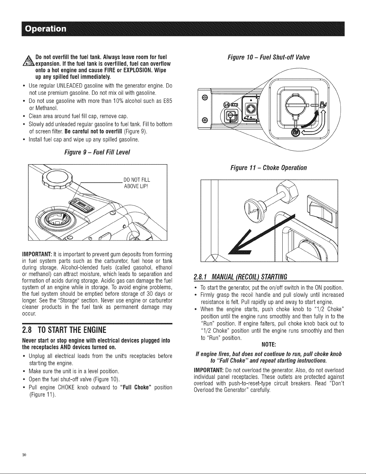
• Makesure the unit is in a level position.
• Openthe fuel shut-off valve (Figure10).
• Pull engine CHOKEknob outward to "Full Choke" position
(Figure11).
Figure 10 - Fuel Shut-off Valve
i
2.8.1 MANUAL_ STARTING
• To start the generator,put the on/off switch in the ONposition.
• Firmly grasp the recoil handle and pull slowly until increased
resistanceis felt. Pull rapidly up and awayto start engine.
• When the engine starts, push choke knob to "1/2 Choke"
position until the engine runs smoothly and then fully in to the
"Run" position. If engine falters, pull choke knob back out to
"1/2 Choke" position until the engine runs smoothly and then
to "Run" position.
NOTE:
If enginefires, but doesnot continueto run, pull choke knob
to "Furl Choke" and repeatstarting instructions.
IMPORTANT:Do not overloadthe generator.Also, do not overload
individual panel receptacles.These outlets are protected against
overload with push-to-reset-type circuit breakers. Read "Don't
Overloadthe Generator" carefully.
1o
2.8.1 ELECTRICSTARtiNG(XG7OOOE& XGSOOOE)
• Tostart the engine,pressandhold the Start/Run/Stopswitch in
the "Start" position. The enginewill crankand attemptto start.
Whenthe enginestarts, releasethe switch to the run position.
• When the engine starts, push choke knob to "1/2 Choke"
position until the engine runs smoothly andthen fully in to the
"Run" position. If engine falters, pull choke knob back out to
"1/2 Choke" position until the engine runs smoothly and then
to "Run" position.
• This generator is also equippedwith a manual recoil starter
which may be usedif the battery is discharged.
NOTE:
The engineStart/Run/Stop switch mustbe in the RUN
position when using the manualrecoil starter.
2.9 STOPPINGTHEENGINE
* Shutoff all loads,then unplugthe electricalloadsfrom generator
panelreceptacles.Neverstart or stop the engine with electrical
devices pluggedin andturned on.
* Let engine run at no-load for several minutes to stabilize the
internaltemperaturesof engineandgenerator.
, Move Start/Run/Stopor On/Offswitch to the "Off" position.
* Closefuel valve.
2.10LOWOILPRESSURESHUTDOWN SYSTEM
The engineis equippedwith a low oil pressure sensor that shuts
down the engineautomaticallywhen the oil pressuredrops below
5 psi. A delay built into the low oil shutdown system allows oil
pressureto build during starting. The delay allows the engine to
run for about 10 secondsbeforesensingoil pressure.If the engine
shuts down by itself andthe fuel tank has enoughgasoline,check
engineoil level.
2.10.1RESTARtiNG
Iftrying to restartthe enginewithin 10seconds after it shutsdown,
the enginemay NOTstart. The system needs5 to 10 secondsto
reset.
If the engine is restarted after such a shutdown and the low oil
pressurehas not been corrected,the enginewill run for about 10
seconds as describedabove andthen stop.
2.11CHARGINGTHEBATTERY(XGTOOOE&XG8OOOE)
Do not permit smoking, open flame, sparks
or any other source of heat around a battery.
Wear protective goggles, rubber apron and
rubber gloves when working around a battery.
Battery electrolyte fluid is an extremely
corrosive sulfuric acid solution that can cause
severe burns, if spill occurs flush area with
clear water immediately.
Storage batteries give off explosive hydrogen
gas while recharging. An explosive mixture will
remain around the battery for a long time after
it has been charged. The slightest spark can
ignite the hydrogen and cause an explosion.
Such an explosion can shatter the battery and
cause blindness or other serious injury.
Use batterycharger plug to keepthe battery chargedand ready
for use. Batterycharging should be done in a dry location.
1. Plugcharger into "Battery ChargerInput" jack, located on the
control panel.Plug wall receptacleend of the battery charger
into a 120 Volt AC wall outlet.
2. Unplugbattery chargerfrom wall outlet and control paneljack
when generatoris going to be in use.
NOTE:
Do not use the battery chargerfor more than 48 hoursat one
charge.
3.1 MAINTENANCESCHEDULE
Follow the calendar intervals. More frequent service is required
when operatingin adverseconditions noted below.
CheckOil Level
ChangeOil and Oil Filter:!:
CleanSparkArrestor Screen
ServiceAir Cleaner
ReplaceSpark Plug
$
"k
At Each Use
*Every Season/Every100 Hours
*Every Season/Every100 Hours
**Every Season/Every200 Hours
EverySeason
Changeoil after first 30 hours of operation then every season.
Changeoil and oil filter every month when operating under heavy load or in
high temperatures.
Clean more often under dirty or dusty operating conditions. Replace air
cleaner parts if very dirty.
3.2 PRODUCTSPECIFICATIONS
3.2.1 GENERATORSPEC/F/CATIONS
Model # ............................................................... 005800-0, 005747-0
RatedMax. Power................................................................... 8.0 kW**
Surge Power................................................................................ 10 kW
RatedACVoltage...................................................................... 120/240
RatedMax AC Load
Current @ 240V............................................................. 33.3 Amps**
Current @ 120V............................................................. 66.7 Amps**
RatedFrequency.................................................... 60 Hz @ 3600 RPM
Phase................................................................................ SinglePhase
RatedDCVoltage...................................................................... 12 Volts
BatteryType.................................................................... 10 AH, 12VDC
11
Model # ............................................................... 005797-0, 005798-0
RatedMax. Power................................................................... 7.0 kW**
Surge Power............................................................................. 8.75 kW
RatedACVoltage...................................................................... 120/240
RatedMax ACLoad
Current @ 240V............................................................. 29.2 Amps**
Current @ 120V............................................................. 58.3 Amps**
RatedFrequency.................................................... 60 Hz @ 3600 RPM
Phase................................................................................ SinglePhase
RatedDCVoltage...................................................................... 12 Volts
BatteryType.................................................................... 10 AH, 12VDC
Model # ................................................................................ 885796-0
RatedMax. Power................................................................... 6.5 kW**
Surge Power............................................................................. 8.13 kW
RatedACVoltage...................................................................... 120/240
RatedMax ACLoad
Current@ 240V............................................................. 27.1 Amps**
Current@ 120V............................................................. 54.2 Amps**
RatedFrequency.................................................... 60 Hz @ 3600 RPM
Phase................................................................................ SinglePhase
RatedDCVoltage...................................................................... 12 Volts
** Maximumwattageandcurrentaresubjectto,andlimitedby,suchfactors
asfuelBtucontent,ambienttemperature,altitude,enginecondition,etc..
Maximumpowerdecreasesabout3.5%for each1,000feetabovesealevel;
andwillalsodecreaseabout1%for each6° C (10° F)above16° C(60° F)
ambienttemperature.
3.2.2 ENGINESPECIFICAtiONS
RatedHorsepower@ 3600 RPM.................................................... 14.5
Displacement............................................................................... 410cc
Spark PlugType................................... ChampionRO14YOor Equivalent
Spark Plug Gap............................................... 0.030 inch or (0.76 mm)
GasolineCapacity............................................................ 9 U.S. gallons
Oil Type.................................... SeeChart in "Adding EngineOil"Section
Oil Capacity................................................ w/Filter Change = 1.5 Qts.
w/o FilterChange= 1.2 Qts.
Run Time/FuelConsumption-l/2 Load .. 10 Hours/ .73 gallons per hour
Class I1EmissionCertified
3.2.3 EM/SS/ONS/NFORMATiON
The Environmental Protection Agency (EPA) and California Air
Resource Board (CARB) requirethat your generator comply with
exhaust and evaporative emission standards. This generator is
certified to meet the applicable EPAand CARB emission levels.
Additional information regardingthe requirementsset by EPAand
CARBis as follows:
It is important that you follow the maintenance specifications
provided in this manualto ensurethat your enginecomplies with
the applicableemission standardsfor the duration of the engine's
life. This engine is certified to operateon gasoline. The emission
control system on your generatorconsists of the following:
* FuelSystem * Air Induction System
FuelTank - Intakepipe/manifold
FuelCap - Air cleaner
Carburetor • IgnitionSystem
FuelLines - Spark plug
* EvaporativeControl System - Ignition module
CarbonCanister * ExhaustSystem
VaporHoses _ PulseAir InjectionValve
Muffler
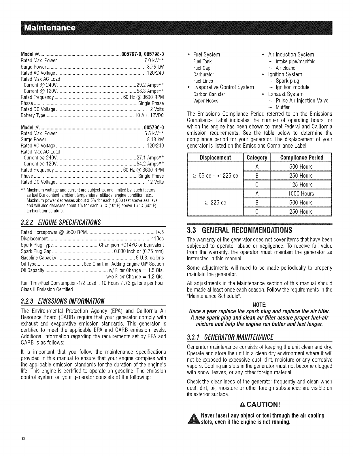
The Emissions Compliance Period referred to on the Emissions
Compliance Label indicates the number of operating hours for
which the engine has been shown to meet Federaland California
emission requirements. See the table below to determine the
compliance period for your generator.The displacement of your
generatoris listed onthe Emissions ComplianceLabel.
Displacement Category CompliancePeriod
A 500 Hours
_>66 cc- < 225 cc B 250 Hours
C 125 Hours
A 1000 Hours
_>225 cc B 500 Hours
C 250 Hours
3.3 GENERALRECOMMENDATIONS
Thewarranty of the generatordoes not cover itemsthat havebeen
subjected to operator abuse or negligence. To receivefull value
from the warranty, the operator must maintain the generator as
instructed in this manual.
Some adjustments wilt need to be made periodically to properly
maintainthe generator.
All adjustments in the Maintenancesection of this manual should
be madeat leastonce eachseason. Followthe requirementsinthe
"MaintenanceSchedule".
NOTE:
Oncea year replace the spark plug and replace the air filter.
A new spark plug and clean air filter assure proper fuel-air
mixture and help the engine run better and last longer.
3.3.1 GENERATORMAINTENANCE
Generatormaintenanceconsists of keepingthe unit clean and dry.
Operateand storethe unit in a cleandry environmentwhere it will
not be exposed to excessive dust, dirt, moisture or any corrosive
vapors.Coolingair slots in the generatormust not becomeclogged
with snow, leaves,or any otherforeign material.
Checkthe cleanlinessof the generatorfrequently and clean when
dust, dirt, oil, moisture or other foreign substances arevisible on
its exteriorsurface.
,&CAUTION!
,_ Never insertany object or toolthroughthe air cooling
slots, even if the engine is not running.
12
NOTE:
DO NOTuse a garden hose to cleangenerator. Water can
enterthe engine fuelsystem and cause problems. In addition,
if water entersthe generatorthroughcoolingair slots,some
water will be retainedin voidsand crevicesof the rotor
and stator winding insulation.Water and dirt buildupon the
generatorinternal windings will eventuallydecrease the
insulationresistanceof these windings.
3.3.2 TOCLEANTHEGENERATOR
• Usea damp cloth to wipe exteriorsurfaces clean.
• A soft, bristlebrush may be used to loosen caked on dirt, oil,
etc.
• A vacuum cleaner may be used to pick up loose dirt and
debris.
• Low pressureair (not to exceed25 psi) may be used to blow
awaydirt. Inspectcoolingairslots andopeningsonthe generator.
Theseopenings must bekept clean and unobstructed.
3.3.3 ENG/NEMA/NTENANCE
,A CAUTION!
,_ When workingonthe generator,alwaysdisconnect
negativecable frombattery.Also disconnectsparkplug
wire from sparkplugand keepwire away from spark
plug.
3.3.4 CHECKINGOILLEVEL
See the "BEFORESTARTINGTHE GENERATOR"section for
information on checking the oil level. The oil level should be
checkedbeforeeach use,or at leasteveryeight hoursof operation.
Keepthe oil levelmaintained.
3.3.5 CHANG/NGTIlE O/LANOOILFILTER
Changethe oil and filterafter the first 30 hours of operation.Change
the oil every 100 hours or every seasonthereafter.If running this
unit underdirty or dusty conditions, or in extremelyhot weather,
changethe oil more often.
,_ Hotoil may causeburns.Allow engine to cool before
draining oil. Avoid prolongedor repeatedskin exposure
with usedoil. Thoroughlywashexposedareas with soap.
Use the following instructionsto changethe oil:
• Cleanarea aroundoil drain cap.
• Removeoil draincap from the drainhose and oilfill plugto drain
oil completely into a suitable container.
• Whenoil has completelydrained,install oil drain cap andtighten
securely.
• Place a suitable container beneath the oil filter and turn
filter counterclockwise to remove. Discard according to local
regulations.
• Coat gasket of new filter with clean engine oil. Turn filter
clockwise until gasket contacts lightly with filter adapter.Then
tightenan additional3/4 turn.
• Filloil sumpwithrecommendedoil andreplacetheoilfill plug.(See
"Before Startingthe Generator"for oil recommendations).
• Wipe up any spilled oil.
• Disposeof used oil at a proper collection center.
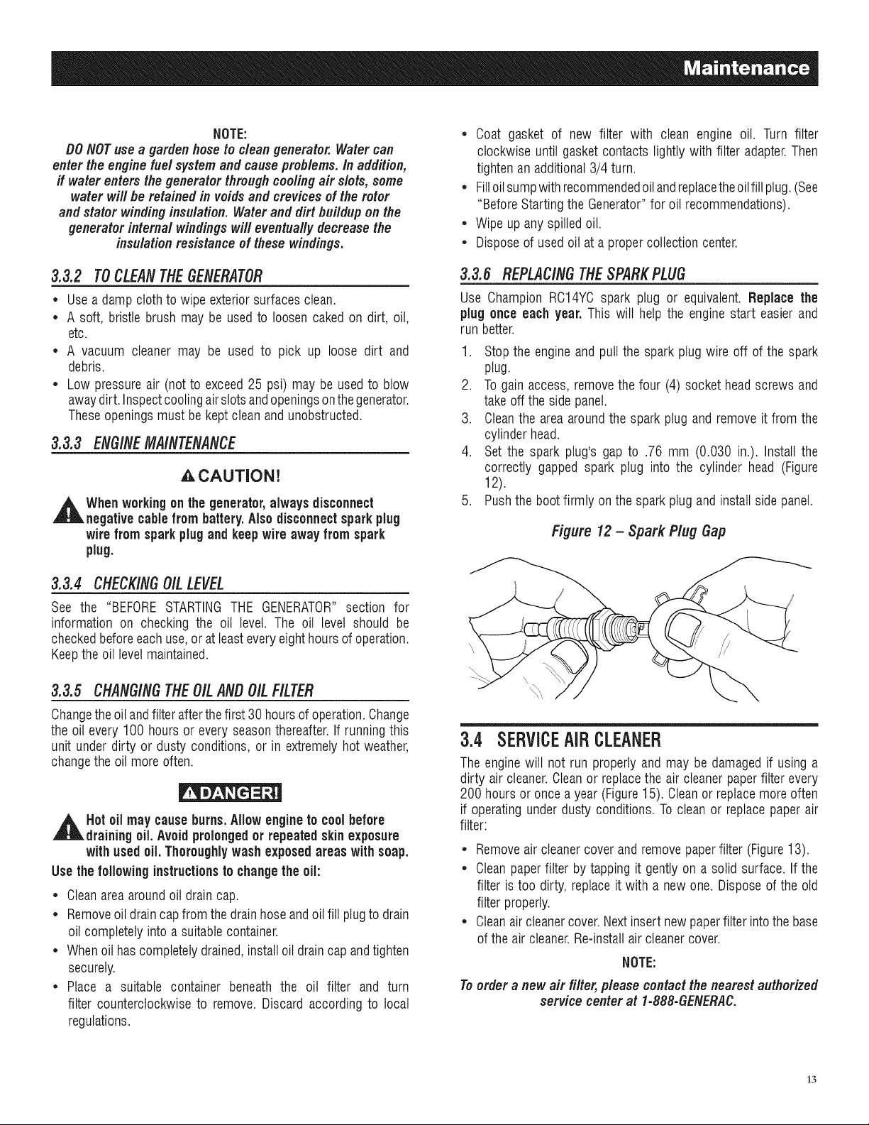
3.3.6 REPLACINGTHESPARKPLUG
Use Champion RC14YCspark plug or equivalent. Replace the
plug once each year. This will help the engine start easier and
run better.
1. Stop the engineand pull the spark plug wire off of the spark
plug.
2. To gain access, remove the four (4) socket head screws and
takeoff the side panel.
3. Cleanthe area aroundthe spark plug and remove it from the
cylinder head.
4. Set the spark plug's gap to .76 mm (0.030 in.). Install the
correctly gapped spark plug into the cylinder head (Figure
12).
5. Pushthe bootfirmly on the sparkplug and install side panel.
Figure 12 - Spark Plug Gap
3.4 SERVICEAIRCLEANER
The enginewill not run properly and may be damaged if using a
dirty air cleaner.Cleanor replacethe air cleaner paperfilter every
200 hours or once a year (Figure15). Cleanor replacemore often
if operating underdusty conditions. To clean or replace paper air
filter:
• Removeair cleanercover andremove paperfilter (Figure13).
• Clean paperfilter by tapping it gently on a solid surface. If the
filter is too dirty, replace it with a new one. Disposeof the old
filter properly.
• Cleanair cleanercover.Nextinsert new paperfilter into the base
of the air cleaner.Re-installair cleaner cover.
NOTE:
Toorder a new air filter, please contact the nearest authorized
service center at 1-888-GENERAC.
13
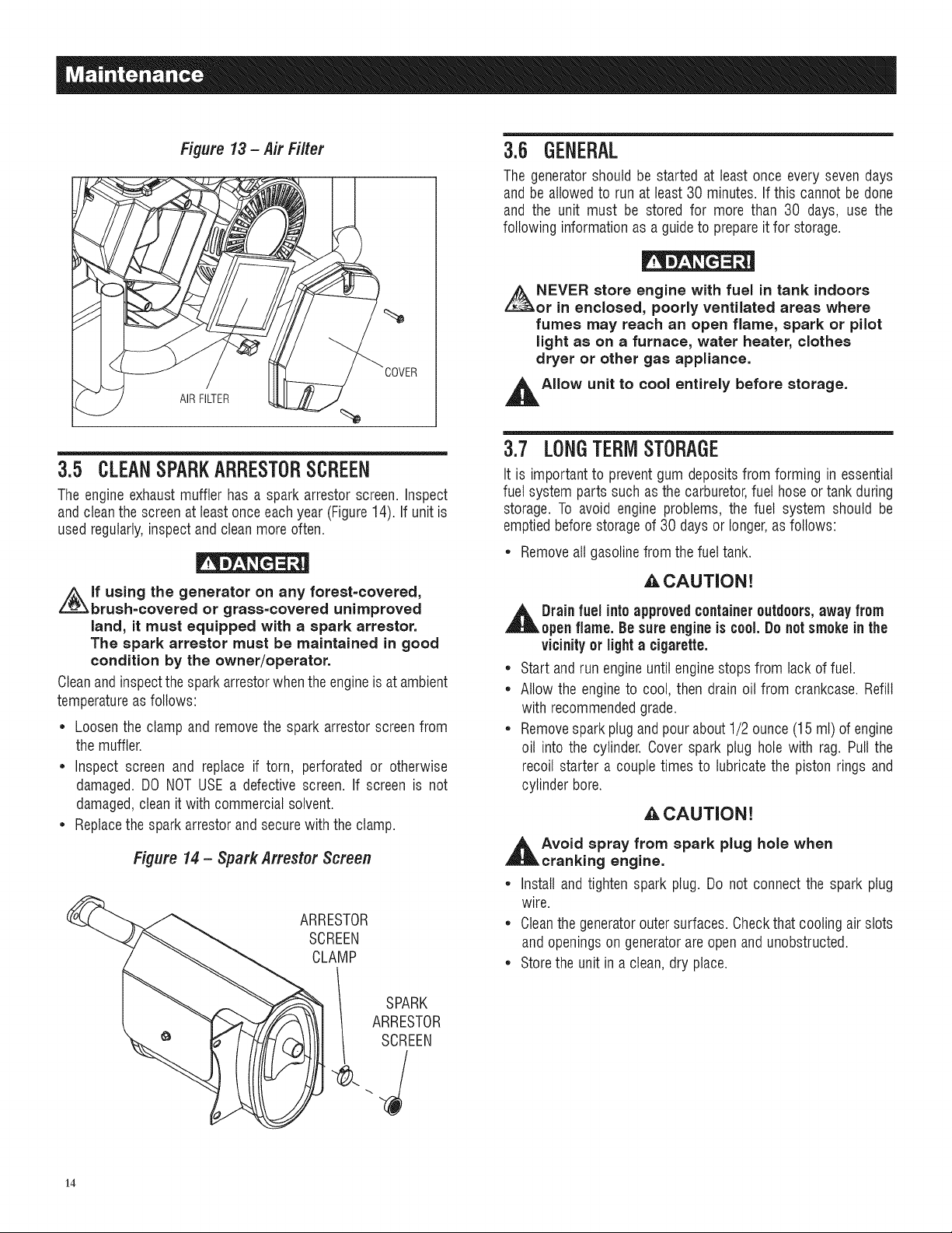
Figure 13- Air Filter
AIR FILTER
3.5 CLEANSPARKARRESTORSCREEN
The engine exhaust muffler has a spark arrestor screen. Inspect
and cleanthe screenat leastonce each year (Figure14). If unit is
used regularly,inspect and clean more often.
i_lf using the generator on any forest=covered,
brush=covered or grass=covered unimproved
land, it must equipped with a spark arrestor.
The spark arrestor must be maintained in good
condition by the owner/operator.
Cleanand inspectthe spark arrestorwhen the engineis at ambient
temperatureas follows:
* Loosen the clamp and remove the spark arrestor screenfrom
the muffler.
* Inspect screen and replace if torn, perforated or otherwise
damaged. DO NOT USE a defective screen. If screen is not
damaged,clean it with commercialsolvent.
* Replacethe spark arrestor and secure with the clamp.
Figure 14 - Spark Arrestor Screen
ARRESTOR
SCREEN
CLAMP
SPARK
ARRESTOR
SCREEN
3.6 GENERAL
The generatorshould be started at least once every seven days
andbe allowedto run at least 30 minutes. If this cannot be done
and the unit must be stored for more than 30 days, use the
following information as a guideto prepareit for storage.
NEVER store engine with fuel in tank indoors
or in enclosed, poorly ventilated areas where
fumes may reach an open flame, spark or pilot
light as on a furnace, water heater, clothes
dryer or other gas appliance.
,l_AIIow unit to cool entirely before storage.
3.7 LONGTERMSTORAGE
It is important to prevent gum deposits from forming in essential
fuel system parts such as the carburetor,fuel hose or tank during
storage. To avoid engine problems, the fuel system should be
emptiedbefore storageof 30 days or longer,as follows:
* Removeall gasolinefrom the fuel tank.
_,CAUTION!
,l& Drain fuel intoapprovedcontaineroutdoors,away from
openflame. Besure engineis c00i. Donotsmokein the
vicinityor lighta cigarette.
* Start and run engineuntil engine stops from lack of fuel.
* Allow the engineto cool, then drain oil from crankcase. Refill
with recommendedgrade.
* Removesparkplugand pourabout 1/2 ounce (15 ml) of engine
oil into the cylinder. Cover spark plug hole with rag. Pull the
recoil starter a couple times to lubricatethe piston rings and
cylinder bore.
A CAUTION!
,l_Avoid spray from spark plug hole when
cranking engine.
* Install and tighten spark plug. Do not connect the spark plug
wire.
* Cleanthe generatorouter surfaces. Checkthat cooling air slots
and openingson generatorare open and unobstructed.
* Storethe unit in a clean,dry place.
14
3.8 OTHERSTORAGETiPS
• Do not store gasolinefrom one seasonto another.
• Replaceany gasolinecan that starts to rust. Rust and/or dirt in
the gasoline will cause problems with the carburetor and fuel
system.
• If possible,store the unit indoors and cover it to give protection
from dust and dirt. Cover the unit with a suitable protective
coverthat does not retainmoisture.
• BE SURETO EMPTY THE FUEL TANK. If it is not practical
to empty the fuel tank and the unit is to be stored for some
time, use a commercially availablefuel stabilizeraddedto the
gasolineto increasethe life of the gasoline.
,A CAUTION!
,_ NEVER cover the generator while engine and
exhaust area are warm,
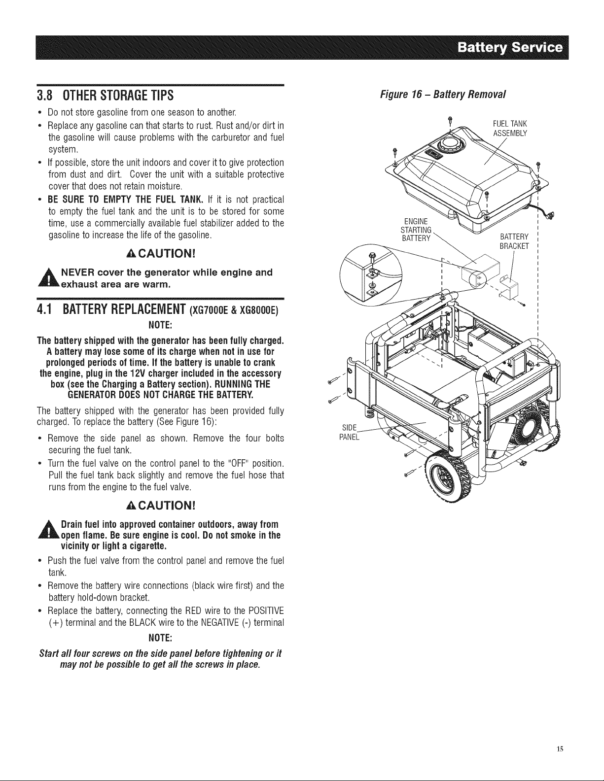
4.1 BATTERYREPLACEMENT(XG7000E&XGS000E)
NOTE:
The batteryshippedwiththe generatorhas been fully charged.
A batterymay losesomeof its chargewhen not in use for
prolongedperiodsof time. If the batteryis unableto crank
the engine,plug inthe 12V chargerincludedinthe accessory
box(see the Charging a Batterysection).RUNNINGTHE
GENERATORDOESNOTCHARGETHEBATTERY.
The battery shipped with the generator has been provided fully
charged.To replacethe battery (SeeFigure16):
• Remove the side panel as shown. Remove the four bolts
securingthe fuel tank.
• Turn the fuel valve on the control panel to the "OFF"position.
Pull the fuel tank back slightly and removethe fuel hose that
runs from the engineto the fuel valve.
_CAUTION!
,_ Drainfuel into approvedcontaineroutdoors,awayfrom
open flame. Be sureengine is cool.Donot smoke in the
vicinityor light a cigarette.
• Push the fuel valvefrom the control paneland removethe fuel
tank.
• Removethe battery wire connections(black wire first) and the
battery hold-down bracket.
• Replacethe battery, connectingthe REDwire to the POSITIVE
(+) terminal and the BLACKwire to the NEGATIVE(-) terminal
NOTE:
Start aft four screws onthe side panel beforetighteningor it
may not be possible to get all the screws in place.
SIDE
PANEL
Figure 16 - Battery Removal
1_ FUELTANK
ASSEMBLY
if
ENGINE
STARTIN(
BATTERY
BATTERY
BRACKET
15
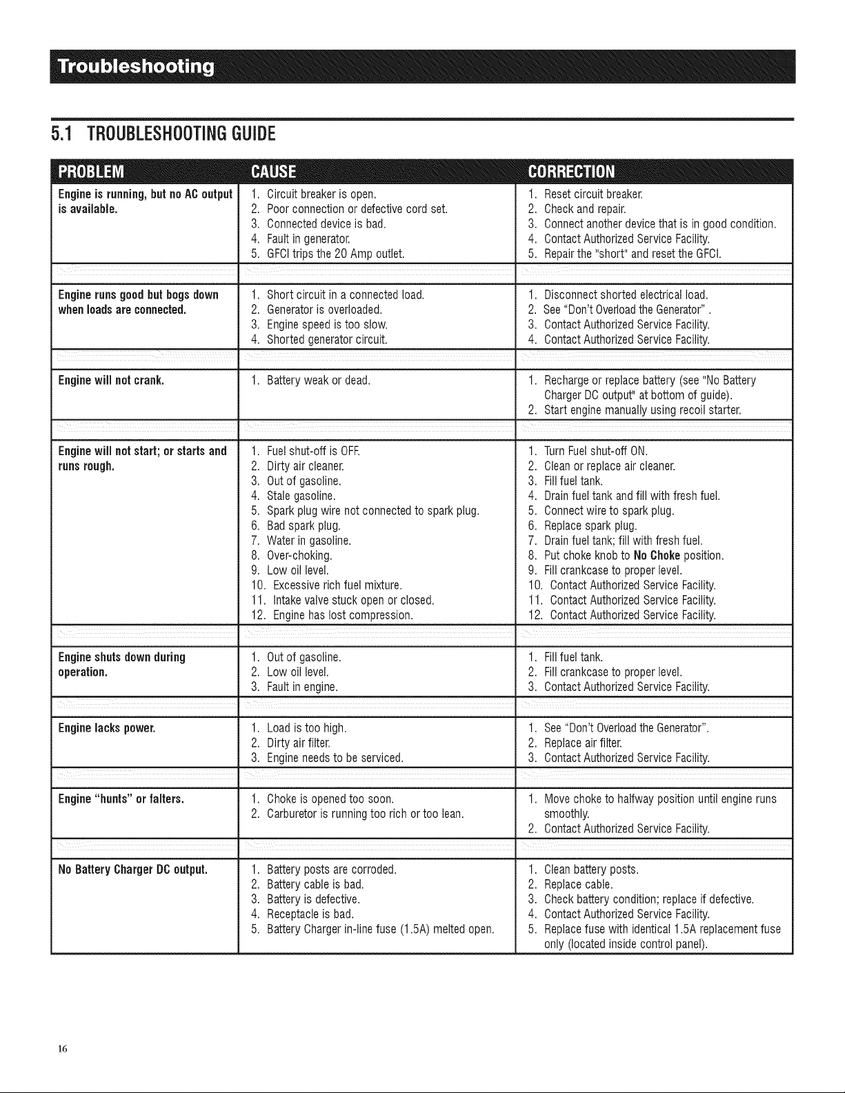
5.1 TBOUBLESHOOTINGGUIDE
Engineis running,but noAC output
is available.
1. Circuit breakeris open.
2. Poor connection or defectivecord set.
3. Connecteddevice is bad.
4. Fault in generator.
5. GFCItrips the 20 Amp outlet.
1. Reset circuit breaker.
2. Check and repair.
3. Connect another device that is in good condition.
4. ContactAuthorizedService Facility.
5. Repairthe "short" and reset the GFCI.
I
. =
Engine runs good but begs down 1. Short circuit in a connected load. 1. Disconnect shorted electrical load.
whenloads are connected. 2. Generatoris overloaded. 2. See"Don't Overloadthe Generator".
3. Engine speed is too slow. 3. ContactAuthorizedService Facility.
4. Shorted generatorcircuit. 4. ContactAuthorizedService Facility.
Engine will not crank. 1. Battery weak or dead. 1. Rechargeor replacebattery (see "No Battery
ChargerDC output" at bottom of guide).
2. Start enginemanually using recoil starter.
Enginewiil not start; or starts and
runsrough.
,
2.
3.
4.
5.
6.
Fuelshut-off is OFE 1.
Dirty air cleaner. 2.
Out of gasoline. 3.
Stale gasoline. 4.
Spark plug wire not connectedto spark plug. 5.
Bad spark plug. 6.
TurnFuelshut-off ON.
Cleanor replaceair cleaner.
Fillfuel tank.
Drainfuel tank andfill with fresh fuel.
Connectwire to spark plug.
Replacespark plug.
7. Water in gasoline.
8. Over-choking.
9. Low oil level.
10. Excessiverich fuel mixture.
11. Intakevalve stuck open or closed.
12. Enginehas lost compression.
7. Drain fuel tank; fill with fresh fuel.
8. Put choke knobto No Chokeposition.
9. Fill crankcaseto proper level.
10. Contact AuthorizedService Facility.
11. Contact AuthorizedService Facility.
12. Contact AuthorizedService Facility.
i i
Engine shuts downduring 1. Out of gasoline. 1. Fillfuel tank.
operation. 2. Low oil level. 2. Fill crankcaseto proper level.
3. Fault in engine. 3. ContactAuthorizedService Facility.
I
Engine lacks power. 1. Load is too high. 1. See"Don't OverloadtheGenerator".
2. Dirty air filter. 2. Replaceair filter.
3. Engine needsto be serviced. 3. ContactAuthorizedService Facility.
Engine "hunts" or falters. 1. Choke is openedtoo soon. 1. Move choke to halfway position until engine runs
2. Carburetoris running too rich or too lean. smoothly.
2. ContactAuthorizedService Facility.
NoBatteryChargerDOoutput. 1. Battery posts are corroded.
2. Battery cable is bad.
3. Battery is defective.
4. Receptacleis bad.
5. Battery Chargerin-line fuse (1.5A) melted open.
1. Cleanbattery posts.
2. Replacecable.
3. Check battery condition; replace if defective.
4. ContactAuthorizedService Facility.
5. Replacefuse with identical 1.5A replacementfuse
only (located inside control panel).
16

17
CALIFORNIA AND FEDERAL EMISSION CONTROL WARRANTY STATEMENT
YOUR WARRANTY RIGHTS AND OBLIGATIONS
The California Air Resources Board (CARB) and the United States Environmental Protection Agency (EPA), together with Generac
Power Systems, Inc. (Generac), are pleased to explain the Emission Control System warranty on your new 2008 and later
generator. New equipment that use small spark-ignited engines must be designed, built, and equipped to meet stringent anti-
smog standards for the state of California and the federal government. Generac will warrant the emission control system on your
generator for the period of time listed below provided there has been no abuse, neglect, unapproved modification or improper
maintenance of your equipment.
Your emission control system may include parts such as the: carburetor, ignition system, catalytic converter, fuel tank, fuel lines,
fuel cap, valves, carbon canister, filters, vapor hoses, clamps, connectors, and other associated emission-related components (if
equipped).
MANUFACTURER'S WARRANTY COVERAGE:
This emission control system is warranted for two years. If, during such warranty period, any emission-related part on your
equipment is found to be defective in materials or workmanship, repairs or replacement will be performed by a Generac Authorized
Warranty Service Dealer.
OWNER'S WARRANTY RESPONSIBILITIES:
As the generator owner, you are responsible for the completion of all required maintenance as listed in your factory supplied
Owner's Manual. For warranty purposes, Generac recommends that you retain all receipts covering maintenance on your
generator, but Generac cannot deny warranty solely due to the lack of receipts.
As the generator owner, you should be aware that Generac may deny any and/or all warranty coverage or responsibility if your
generator, or a part/component thereof, has failed due to abuse, neglect, improper maintenance or unapproved modifications, or
the use of counterfeit and/or "grey market" parts not made, supplied or approved by Generac.
You are responsible for contacting a Generac Authorized Warranty Dealer as soon as a problem occurs. The warranty
repairs should be completed in a reasonable amount of time, not to exceed 30 days,
Warranty service can be arranged by contacting either your selling dealer or a Generac Authorized Warranty Service Dealer. To
locate the Generac Authorized Warranty Service Dealer nearest you, call our toll free number:
1=800=333=1322
IMPORTANT NOTE: This warranty statement explains your rights and obligations under the Emission Control System Warranty
(ECS Warranty), which is provided to you by Generac pursuant to California and federal law. See also the "Generac Limited
Warranties for Generac Power Systems, Inc.," which is enclosed herewith on a separate sheet, also provided to you by Generac.
Note that this warranty shall not apply to any incidental, consequential or indirect damages caused by defects in materials or
workmanship or any delay in repair or replacement of the defective part(s). This warranty is in place of all other warranties,
expressed or implied. Specifically, Generac makes no other warranties as to the merchantability or fitness for a particular purpose.
Some states do not allow limitations on how long an implied warranty lasts, so the above limitation may not apply to you.
The ECS Warranty applies only to the emission control system of your new equipment. If there is any conflict in terms between
the ECS Warranty and the Generac Warranty, the Generac Warranty shall apply. Both the ECS Warranty and the Generac Warranty
describe important rights and obligations with respect to your new engine.
Warranty service can be performed only by a Generac Authorized Warranty Service Facility. When requesting warranty service,
evidence must be presented showing the date of the sate to the original purchaser/owner.
If you have any questions regarding your warranty rights and responsibilities, you should contact Generac at the following address:
ATTENTION WARRANTY DEPARTMENT
GENERAC POWER SYSTEMS, INC.
RO. BOX 297 ', WHITEWATER, WI 53190
Part 1
Part No. 0H1913 Rev.A 01/09
18
EMiSSiON CONTROL SYSTEM WARRANTY
Emission Control System Warranty (ECS warranty) for equipment using small spark-ignited engines:
(a) Applicability: This warranty shall apply to equipment that uses small off-road engines. The ECS Warranty period shall begin
on the date the new equipment is purchased by/delivered to its original, end-use purchaser/owner and shall continue for 24
consecutive months thereafter.
(b) General Emissions Warranty Coverage: Generac warrants to the original, end-use purchaser/owner of the new engine or
equipment and to each subsequent purchaser/owner that the ECS when installed was:
(1) Designed, built and equipped so as to conform with all applicable regulations; and
(2) Free from defects in materials and workmanship which cause the failure of a warranted part at any time during the ECS
Warranty Period.
(c) The warranty on emissions-related parts will be interpreted as follows:
(1) Any warranted part that is not scheduled for replacement as required maintenance in the Owner's Manual shall be
warranted for the ECS Warranty Period. If any such part fails during the ECS Warranty Period, it shall be repaired or
replaced by Generac according to Subsection (4) below. Any such part repaired or replaced under the ECS Warranty shall
be warranted for the remainder of the ECS Warranty Period.
(2) Any warranted part that is scheduled only for regular inspection as specified in the Owner's Manual shall be warranted
for the ECS Warranty Period. A statement in the Owner's Manual to the effect of "repair or replace as necessary" shall not
reduce the ECS Warranty Period. Any such part repaired or replaced under the ECS Warranty shall be warranted for the
remainder of the ECS Warranty Period.
(3) Any warranted part that is scheduled for replacement as required maintenance in the Owner's Manual shall be warranted
for the period of time prior to first scheduled replacement point for that part. If the part fails prior to the first scheduled
replacement, the part shall be repaired or replaced by Generac according to Subsection (4) below. Any such emissions-
related part repaired or replaced under the ECS warranty shall be warranted for the remainder of the period prior to the first
scheduled replacement point for that part.
(4) Repair or replacement of any warranted, emissions-related part under this ECS Warranty shall be performed at no charge to
the owner at a Generac Authorized Warranty Service Facility.
(5) Notwithstanding the provisions of subsection (4) above, warranty services or repairs must be provided at Generac
Authorized Service Facilities.
(6) When the engine is inspected by a Generac Authorized Warranty Service Facility, the purchaser/owner shall not be held
responsible for diagnostic costs if the repair is deemed warrantable.
(7) Throughout the ECS Warranty Period, Generac shall maintain a supply of warranted emission-related parts sufficient to
meet the expected demand for such parts.
(8) Any Generac authorized and approved emission-related replacement parts may be used in the performance of any ECS
warranty maintenance or repairs and will be provided without charge to the purchaser/owner. Such use shall not reduce
Generac ECS Warranty obligations.
(9) Unapproved, add-on, modified, counterfeit and/or "grey market" parts may not be used to modify or repair a Generac
engine. Such use voids this ECS Warranty and shall be sufficient grounds for disallowing an ECS Warranty claim. Generac
shall not be held liable hereunder for failures of any warranted parts of Generac equipment caused by the use of such an
unapproved, add-on, modified, counterfeit and/or "grey market" part.
EMISSION RELATED PARTS MAY INCLUDE THE FOLLOWING (IF EQUIPPED)"
1) FUEL SYSTEM 3) FUEL METERING SYSTEM
A. FUEL TANK A. CARBURETOR AND INTERNAL PARTS
B. FUEL CAP B. PRESSURE REGULATOR
C. FUEL LINE 4) AIR INDUCTION SYSTEM
D. FUEL LINE FITTINGS A. INTAKE MANIFOLD
E. CLAMPS* B. AIR FILTER
F. PRESSURE RELIEF VALVES* 5) IGNITION SYSTEM
2) EVAPORATIVE CONTROL SYSTEM A. SPARK PLUGS
A. CARBON CANISTER B. IGNITION COILS / MODULE
B. CANISTER MOUNTING BRACKETS 6) AIR INJECTION SYSTEM
C. CARBURETOR PURGE PORT A. PULSE AIR VALVE
D. CONTROL VALVES* 7) EXHAUST SYSTEM
E. VAPOR HOSES A. CATALYST
F. PURGE VALVES B. THERMAL REACTOR
G. LIQUID / VAPOR SEPARATOR C. EXHAUST MANIFOLD
H. VACUUM CONTROL DIAPHRAGMS*
*NOTE: As they relate to the Emission Control System.
Part 2
Part N0.0H1913 Rev.A 01/09
19
GENERAC POWER SYSTEMS "TWO YEAR" LiMiTED WARRANTY FOR
XG SERIES PORTABLE GENERATORS
For a period of two years from the date of original sale, Generac Power Systems, Inc. (Generac) warrants its XG Series generators will be free from defects in materials
and workmanship for the items and period set forth below. Generac will, at its option, repair or replace any part which, upon examination, inspection and testing by
Generac or a Generac Authorized Warranty Service Dealer, is found to be defective. Any equipment that the purchaser/owner claims to be defective must be returned to
and examined by the nearest Generac Authorized Warranty Service Dealer.All transportation costs under the warranty, including return to the factory, are to be borne and
prepaid by the purchaser/owner. This warranty applies only to GeneracXG Series portable generators and is not transferable from original purchaser. Save your proof-of-
_urchasereceipt. If you do not provide proof of the initial purchase date, the manufacturer's shipping date of the product will be used to determine the warranty period.
WARRANTY SCHEDULE
;onsumerapplicationsarewarrantedfor two (2) years.CommercialandRentalapplicationsarewarrantedfor one(1) yearor 1000hoursmaximum,whichevercomes
first.
CONSUMER APPLiCATiON
YEARONE- 100%(onehundredpercent)coverageon LaborandPart(s)(proofof purchaseandmaintenanceis required):
, All Components
YEARTWO- 100%(onehundredpercent)coverageon Part(s) (proofof purchaseandmaintenanceis required):
, All Components
COMMERCiAL/RENTAL APPLiCATiON
YEARONE- 100%(onehundredpercent)coverageon LaborandPart(s)(proofof purchaseandmaintenanceis required):
,All Components
NOTE: Forthe purpose of this warranty "consumer use" means personal residential household or recreational use by original purchaser. This warranty does not apply
to units used for Prime Power in place of utility where utility power service is present or where utility power service does not normally exist. Once a generator
has experienced commercial or rental use, it shall thereafter be considered a non-consumer use generator for the purpose of this warranty.
All warranty expense allowances are subject to the conditions defined in Generac's Warranty Policies, Procedures and Flat Rate Manual.
THiS WARRANTY SHALL NOT APPLY TO THE FOLLOWING:
Generac portable generators that utilize non-Generac replacement parts.
Costs of normal maintenance and adjustments.
Failures caused by any contaminated fuels, oils or lack of proper oil levels.
Repairs or diagnostics performed by individuals other than Guardian/Generacauthorized dealers not authorized in writing by Generac Power Systems.
Failures due, but not limited, to normal wear and tear, accident, misuse, abuse, negligence or improper use. As with all mechanical devices, the Generac engines need
periodic part(s) service and replacement to perform as designed. This warranty will not cover repair when normal use has exhaustedthe life of a part(s) or engine.
Failures caused by any act of God and other force majeure events beyond the manufactures control.
Damage relatedto rodent and/or insect infestation.
Products that are modified or altered in a manner not authorized by Generac in writing.
Any incidental, consequential or indirect damages caused by defects in materials or workmanship, or any delay in repair or replacement of the defective part(s).
Failuredue to misapplication.
Telephone, cellular phone, facsimile, internet access or other communication expenses.
Living or travel expenses of person(s) performing service, except as specifically included within the terms of a specific unit warranty period.
Expenses relatedto "customer instruction" or troubleshooting where no manufacturing defect is found.
Rentalequipment used while warranty repairs are being performed.
Overnight freight or special shipping costs for replacement part(s).
Overtime, holiday or emergency labor.
Starting batteries, fuses, filters, light bulbs and engine fluids.
HISWARRANTYISIN PLACEOFALLOTHERWARRANTIES,EXPRESSEDORIMPLIED,SPECIFICALLY,GENERACPOWERSYSTEMSMAKESNOOTHERWARRANTIES
ASTOTHEMERCHANTABILITYORFITNESSFORA PARTICULARPURPOSE.Anyimpliedwarrantieswhichareallowedby law,shallbe limitedin durationto the terms
of the expresswarrantyprovidedherein.Somestatesdo not allowlimitationson howlong an impliedwarrantylasts,so the abovelimitationmay notapplyto purchaser/
owner.
GENERACPOWERSYSTEMSONLYLIABILITYSHALLBETHEREPAIRORREPLACEMENTOFPART(S)AS STATEDABOVE.INNOEVENTSHALLGENERACPOWER
SYSTEMSBELIABLEFORANYINCIDENTAL,ORCONSEQUENTIALDAMAGES,EVENIF SUCHDAMAGESAREA DIRECTRESULTOFGENERACPOWERSYSTEMS,
INC.NEGLIGENCE.Somestatesdo notallowtheexclusionorlimitationof incidentalor consequentialdamages,so the abovelimitationsmay notapplyto purchaser/
owner.Purchaser/owneragreesto makenoclaimsagainstGeneracPowerSystems,Inc. basedon negligence.This warrantygivespurchaser/ownerspecificlegalrights.
Purchaser/owneralsomayhaveotherrightsthatvaryfrom stateto state.
GENERAC POWER SYSTEMS, INC.
P.O. BOX 8 " Waukesha, Wl 53187
Ph: (888) GENERAC (438-3722) • Fax: (282) 544-4851
To locate the nearest Authorized Dealer visit our website www.generac.com
PartNo.0H5472 RevisionB (10/20/09) PrintedinU.S.A.
Manual Part No. 0H3530 Revision E (09/30/10) Printedin U.S.A.
MODELO:
005796-0(×G6500),005797-0(×GTO00),
005798-0 (XG7OOOE),005800-0 (×GSO00),
005747-0 (XG8OOOE)
[]
XGSeriesGeneradorportatilde6,500-8,
OS
Introduccion............................................................1
Leaestemanualcornpletamente............................1
Reglasde seguddad...............................................1
indicedeestandares......................................................3
InforrnacionGeneral...............................................4
1.1 Uesempaque..................................................................4
1.1.1 Cajade accesorios............................................4
1.2 Ensamble.......................................................................4
1.2.1 Ensamblajede la rueda......................................4
Operation ...............................................................5
2.1 Conociendoel generador................................................5
2.1.1 Conexionde la bateria........................................6
2.2 Medidorde horas...........................................................6
2.3 Juego de cables y conectores........................................6
2.3.1 Recept_,culoduplexde 120 VAC, 20 Amp.......6
2.3.4 Receptaculode 120/240 VAC, 30 Amp..............6
2.4 Como usar este generador.............................................7
2.4.1 Tierra del sistema..............................................7
2.4.2 Conexi6natierra del generador..........................7
2.4.3 Conexiona tierra det neutroal marcos ...............8
2.4.4 Conexionde las cargos el_ctricas......................8
2.5 No sobrecargueet generador..........................................8
2.6 Guiade refrenciade potencias.......................................8
2.7 Antes de arrancaret generador.......................................9
2.7.1 Agregaraceite de motor.....................................9
2.7.2 A_adirgasolina..................................................9
2.8 Arranquedel motor ......................................................10
2.8.1 Arranquemanual (recule).................................10
2.8.2 Arranqueetectrico (XG7000E& SG8000E).......10
2.9 Deteneret motor .......................................................... 10
2.10 Sistema de apagadopor baja presionde aceite............11
2.10.1 Reiniciar..........................................................11
2.11 Cargade la bateria.......................................................11
iVlantenimiento......................................................11
3.1 Cronogramade mantenimiento..................................... 11
3.2 Especificacionesdel producto......................................11
3.2.1 Especificacionesdelgenerador........................11
3.2.2 Especificacionesdetmotor ..............................12
3.2.3 Informacionsobre emisiones........................... 12
3.3 Recomendacionesgenerales........................................12
3.3.1 Mantenimientodel generador........................... 12
3.3.2 ParaLimpiarelgenerador................................12
3.3.3 Mantenimientodel motor .................................12
3.3.4 Revisaret nivet de aceite.................................. 13
3.3.5 Cambiode aceitey filtro de aceite...................13
3.3.6 Reemptazode la bujia......................................13
3.4 Dar servicio al limpiador de aire................................... 13
3.5 Limpiar pantalladet supresorde chispa........................13
3.6 General........................................................................14
3.7 Almacenamientoa largoplazo......................................14
3.8 Otrosconsejos para almacenamiento........................... 14
Servicio a la bateria.............................................15
4.1 Reemplazode la bateria(XG7000E& XG8000E)..........15
Deteccionde problemas.......................................16
5.1 Guiade deteccionde problemas.................................. 16
Notas....................................................................17
Garantia................................................................18
ADVERTENCIA DE LA PROPOSICION 65 DE CALIFORNIA
El Estado de California sabe que el escapedel motory
algunos de sus componentescausancancer,defectos de
nacimientoy otros da_os reproductivos.
ADVERTENCIA DE LA PROPOSICION 55 DE CALiFORNiA
Esteproductocontieneo emite quimicos que el Estado de
California sabe que causancancer, defectos de nacimiento u
otros da_os reproductivos.
INTRODUCCION
Gracias por comprar este modelo de Generac Power Systems, Inc.
Este modelo es un generadorimpulsado por motor, refrigerado por aire,
compacto y de alto rendimiento disehado para proporcionar energia
electrica para operarcargas electricas dondeno haya servicio publico de
electricidado en reemplazode la red electrica en caso de apagones.
LEAESTEMANUALCOIV1PLETAMENTE
Si alguna parte de este manual no se entiende bien, pongase en
contacto con el concesionario autorizadomas cercano para conocer los
procedimientosde arranque,operaciony servicio.
El operador es responsable del uso apropiadoy seguro de este equipo.
Recomendamos encarecidamente que el operador lea este manual y
entienda completamente todas las instrucciones antes de usar este
equipo. Asimismo recomendamos con igual firmeza el instruir a otros
usuarios para arrancar y operar apropiadamente la unidad. Esto los
preparasi necesitanoperar el equipo en algunaemergencia.
El generadorpuedeoperar en forma segura, eficiente y confiable solo si
se le ubica, se le opera y mantiene en forma apropiada. Antes de operar
o dar servicio al generador:
* Familiaricese y adhierase estrictamente a todos los codigos y
regulacioneslocales,estatalesy nacionales.
, Estudietodas las advertencias de seguridad en este manual yen el
producto con mucho cuidado.
* Familiaricesecon estemanualy la unidad antes de usarla.
El fabricante no puede anticipar todas las posibles circunstancias
que puedan involucrar peligros. Las advertencias en este manual y
en las etiquetas y calcomanias fijadas en la unidad son, por tanto, no
completamenteinclusivas. Sise usa un procedimiento,metodo de trabajo
o tecnica de operacionque el fabricante norecomienda especificamente,
aseguresede que sea seguro para los demas.Asimismo asegureseque
el procedimiento,metodo de trabajo o tecnica de operacion utilizadano
vuelva inseguro al generador.
LA INFORMACIONCONTENIDAAQU[ SE BASO EN MAQUINAS EN
PRODUCCIONAL MOMENTO DE LA PUBLICACION.GENERACSE
RESERVAEL DERECHODE MODtFICARESTEMANUALENCUALQUIER
MOMENTO.
BEGLASDESEGUBIDAD
A Io largo de esta publicacion, yen Io que respecta a las etiquetas
y calcomanias fijadas en el generador, los bloques de PELtGRO,
ADVERTENCIA,CUIDADOY NOTAse usan para alertar al personal sobre
instrucciones especialessobre una operacionen particular quepuedeser
peligrosasi se ejecuta en forma incorrecta o sin cuidado. Observelascon
cuidado. Sus definicionesson como sigue:
INDICAUNASITUACIONPELiGROSA0 ACCI()N QUE,SI NOSE EVITA,
TRAERACOIVIORESULTADOLA IVIUERTEO UN DANGSERIO.
Indicaunasituaci6npeligrosaoacci6nque,si nose evita,podria
traercomeresultadola muerteounda_oserio.
A,C UIDADO
Indicaunasituaci6n peligrosao acci6n que, si no se evita, puede
traer comeresultado un da_omenor o moderado.
NOTA:
Las notas contienen informacion adicional impertante para un
procedimiento y se les encontrara dentro de/cuerpo de este manual
Estas advertencias de seguridad no pueden eliminar los peligros que
indican. El sentido comuny un estricto cumplimiento de las instrucciones
especiales cuando se realiza la accion o servicio son esenciales para
evitar accidentes.
Ouatro simbolos de seguridad usados comunmente acompahan los
bloquesde PELIGRO,ADVERTENCIAy CUIDADO.El tipo de informacion
que cada uno indica es como sigue:
,_ Este simbolo serbia impertante informaci6ndeseguridad que,
si no se sigue, puedeporteren peligrola seguridad personal
y/o las propiedadesde otros.
Estesimbolo indicaun peligropotencial de explosi6n.
i/_Este simbolo indica un peligropotencialde incendio.
//_kEste simbolo indica un peligropotencial de chequeelectrico.
PELIGBOSGENEBALES
* Nuncaopere en areas cerradaso interiores.
* Porrazonesdeseguridad,elfabricanterecomiendaqueelmantenimiento
de este equipo sea Ilevado a cabo por un concesionario autorizado.
Inspeccione el generador con regularidad, y pongase en contacto
con el concesionario autorizadomD.scercano si necesita repararlo o
conseguir repuestos
* Opere el generador solo en superficies planas y donde no este
expuestoa excesivahumedad,suciedad, polvo o vapores corrosivos.
* Mantengalas manos, pies, ropa, etc, lejos de las correas de traccion,
ventiladoresy otras partes moviles o calientes. Nunca retire ninguna
proteccion de ventiladormientras la unida esteoperando.
* Algunas partes de este generador se calientan mucho durante la
operacion. Mantenga distancia del generador hasta que se haya
enfriado paraevitar quemadurasseveras.
* NO opereel generadoren la Iluvia.
* No altere la construccion del generadorni cambie los controles de
modo que puedancrear una condicion de operacion no segura.
* Nuncaarranqueo detengala unidad con cargas electricasconectadas
alas tomas Y con dispositivos conectados y encendidos.Arranque el
motor y deje quese estabiliceantesde conectar las cargaselectricas.
Desconectetodas las cargaselectricas antesde apagar el generador
* No inserte objetos a traves de las ranuras de enfriamiento de la
unidad.
* AI trabajar con este equipo, mantengase alerta en todo momento.
Nunca trabaje en el equipo cuando este fisica o mentalmente
fatigado.
* .Nunca use el generador ni alguna de sus partes como escal6n.
Pararsesobre la unidad puedetensar y romper partes, y puedetraer
como resultado condiciones peligrosasde operacion como escape de
gases, combustible o aceite.
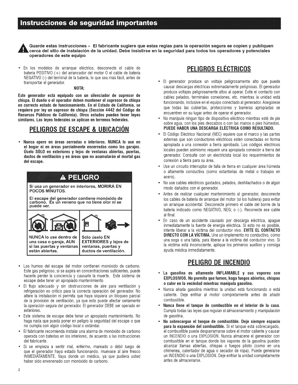
Guarde estas instrucciones - El fabricante sugiere que estas reglas para la operaciCn segura se copien y publiquen
cerca del sitio de instalaciCn de la unidad. Debe insistirse en la seguridad para todos los operadores y potenciales
operadores de este equipo
En los modelos de arranque electrico, desconecte el cable de
bateria POSlTIVO(+) del arrancador del motor 0 el cable de bateria
NEGATIVO(-) del terminal de la bateria, Io que sea mD.sfD.cil,antes de
transportar el generador.
NOTA:
Este geuerador est_i equipado con un silenciador de supresor de
chispa. El due_o o el operadordebenmantener el supresor de chispa
eu correcto estado de funciouamiento.En el Estado de California, se
requiere pot ley un supresor de ¢hispa (Seccicn4442 del Codigode
RecursosP{_blicos de California). 0tros estados puedeu tuner leyes
similares. Las leyes federalesse aplicau en terrenos federales.
PELIGROSDEESCAPE& UBICACI0N
Nunca opere en _ireas cerradas o interiores. NUNCA Io use en
el hogar ni eu ;ireas parcialmente encerradas como los garajes.
Uselo SOLOen exteriores y lejos de ventauas abiertas, puertas,
ductosde ventilacicuyen areas que no acumularan el mortal gas
del escape.
Si usa un generador en interiores, MORIRA EN
POCOS MINUTOS.
El escape del generador contiene mon6xido de
carbono. Es un veneno que no tiene olor ni se
puede ver.
NUNCA Io use dentro de
una casa o garaje, AUN
si las puertas y ventanas
estan abiertas.
Solo _selo EN
EXTERIORES y lejos de
ventanas, puertas y
ductos de ventilacion.
• Los humos del escape del motor contienen monoxido de carbono.
Este gas peligroso, si se aspira en concentracionessuficientes,puede
hacerle perder la conciencia y causarle la muerte. Este sistema de
escape debetener un apropiado mantenimiento
• El flujo adecuado y sin obstrucciones de aire para ventilaci6n y
refrigeracion es critico para la correcta operaci6n del generador.No
altere la instalacion ni permita que haya siquiera un bloqueo parcial
de la provisbn de ventilacion, ya que esto puede afectar seriamente
la operacionsegura del generador.ElgeneradorDEBEser operadoen
exteriores.
• Este sistema de escape debe tener un apropiado mantenimiento. No
haga nada que pueda porteren peligrola seguridaddel escape o que
no cumpla con algun codigo local o estandar.
• Elfabricante recomiendainstalar una alarma de monoxido de carbono
operadacon bateriasen los interiores, deacuerdo alas instrucciones
del fabricante.
• Si se empieza a sentir mal, enfermo, mareado o debil luego de
que el generador haya estado funcionando, muevase al aire fresco
INMEDtATAMENTE.Vaya donde un medico, ya que pudiera usted
haber sido envenenadocon monoxido de carbono.
PELIGROSELI'CTRICOS
• El generador produce un voltaje peligrosamente alto que puede
causar descargas electricas extremadamentepeligrosas. El generador
produce voltajes peligrosamentealtos al operar.Evite el contacto con
cables pelados, terminales conexiones, etc. mientras la unidad esta_
funcionando,inclusive en el equipoconectado algenerador.Asegurese
que todas las cubiertas, protecciones y barreras apropiadas se
encuentrenen su lugar antes de operar el generador.
• No manipule ningun tipo de dispositivo electrico mientras este de pie
sobre agua, con los pies descalzos o con las manos o pies humedos.
PUEDEHABERUNADESCARGAELECTRICAC01Vl0RESULTAD0.
• El Codigo Electrico Nacional (NEC)equiere que el marco y las partes
externas que son conductores electricos esten conectadas enforma
apropiada a una conexion a tierra aprobada. Los ccdigos electricos
locales pueden asimismo requeriruna apropiadaconexion a tierra del
generador.Consulte con un electricista local los requerimientos de
conexiona tierra para su area.
• Use un circuito interruptor de falla de tierra en cualquierD.reahumeda
o altamente conductiva (como estanterias de metal o trabajos en
acero).
• No use cables electricos gastados, pelados,deshilachadoso de algun
modo dafiados con el generador.
• Antes de realizar cualquier mantenimiento al generador, desconecte
los cables de bateriade arranquedel motor (si los hubiera) para evitar
un arranqueaccidental. Desconecteprimero el cable del borne de la
bateria indicado como NEGATIVO,NEG; o (-). Reconecteese cable
al final.
• En caso de un accidente causado por descarga electrica, apague
inmediatamentela fuente de energia electrica. Si esto no es posible,
intente liberar a la victima del conductor vivo. EVITEEL OONTAOTO
DIREOTOCONLAViCTIMA. Uneun implementono conductivo, como
una soga ouna tabla, para liberar a la victima del conductor vivo. Si
la victima esta inconsciente, aplique los primeros auxilios y consiga
ayuda medica inmediatamente.
PELIGR0DEINCENDi0
• La gasolina es altamente INFLAIVIABLE y sus vapores son
EXPLOSIVOS.No permitaque lumen, haga fuegos abiertos, chispas
o calor en la vecindadmientras manipula gasolina.
• Nunca afiada gasolina mientras la unidad esta funcionando o esta
caliente. Deje enfriar al motor completamente antes de ar_adir
combustible.
• Nunca Ilene el tanque de combustibleen el interior de la casa.
Cumplatodas lasleyes que regulanelalmacenamientoy manipulacbn
de gasolina.
• No sebrecargue el tanque de combustible.Deje siempre espacio
para la expansiondel combustible.Si el tanque esta sobrecargado,
el combustible puededesparramarsesobre el motor caliente y causar
un INCENDIOouna EXPLOSION.Nunca almacene el generadorcon
combustible en el tanque donde los vapores de la gasolina pueden
alcanzar llamas abiertas, chispas o fuegos piloto (como en una
chimenea, calentador de agua o secador de ropa). Puedegenerarse
un INOENDIOo una EXPLOSION.Dejeenfriar la unidad completamente
antes de almacenarse.
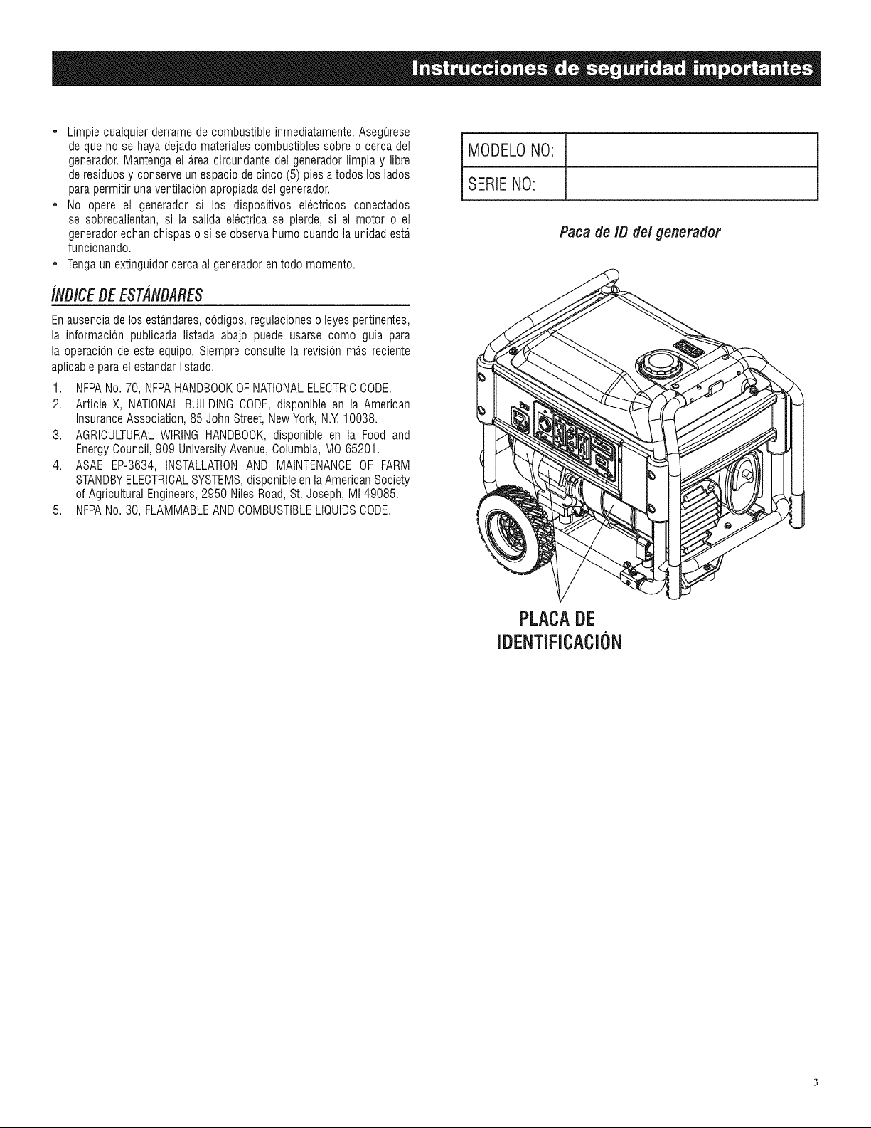
* Limpiecualquierderramedecombustibleinmediatamente.Asegurese
dequenosehayadejadomaterialescombustiblessobreocercadel
generador.Mantengaela.reacircundantedelgeneradorlimpiay libre
deresiduosyconserveunespaciodecinco(5)piesatodosloslados
parapermitirunaventilacionapropiadadelgenerador.
* Noopereel generadorsi losdispositivoselectricosconectados
sesobrecalientan,silasalidaelectricasepierde,sielmotoroel
generadorechanchispasosiseobservahumocuandolaunidadesta.
funcionando.
* Tengaunextinguidorcercaalgeneradorentodomomento.
/NB/CEBE ESTANBARES
En ausenciade los estandares,codigos, regulacioneso leyes pertinentes,
la informacion publicada listada abajo puede usarse como guia para
la operacion de este equipo. Siempre consulte la revision mas reciente
aplicablepara el estandar listado.
1. NFPANo. 70, NFPAHANDBOOKOFNATIONALELECTRICCODE.
2. Article X, NATIONALBUILDINGCODE,disponible en la American
InsuranceAssociation,85 John Street, NewYork, N.Y.10038.
3. AGRICULTURALWIRING HANDBOOK,disponible en la Food and
EnergyCouncil, 909 University Avenue,Columbia, MO 65201.
4. ASAE EP-3634, INSTALLATIONAND MAINTENANCEOF FARM
STANDBYELECTRICALSYSTEMS,disponible en la American Society
of Agricultural Engineers,2950 Niles Road, St. Joseph, MI 49085.
5. NFPANo. 30, FLAMMABLEAND COMBUSTIBLELIQUIDSCODE.
MODELONO:
SERIENO:
Paca de IB de/generador
PLACADE
IDENTIFICACiON
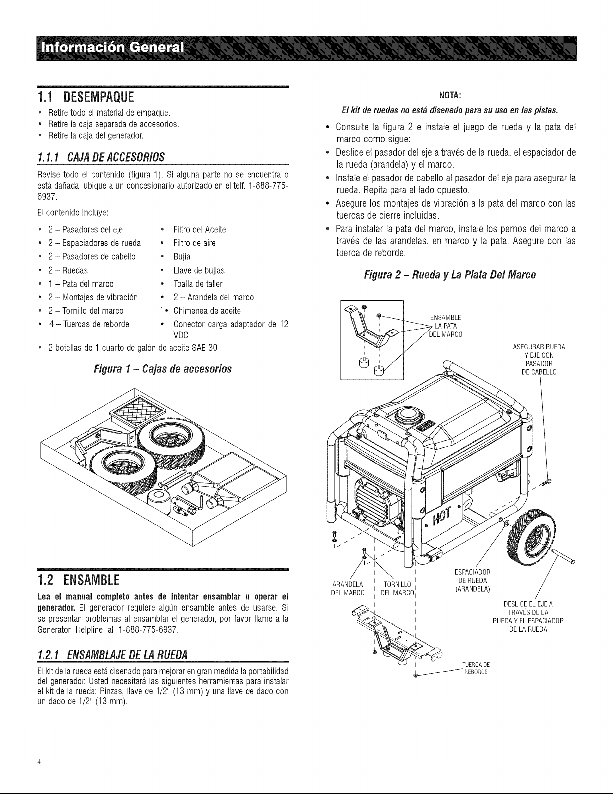
1.1 DESEMPAQUE
• Retiretodo el material de empaque.
• Retirela caja separadade accesorios.
• Retirela caja del generador.
1.1.1 CAJADE ACCESORiOS
Revise todo el contenido (figura 1). Si alguna parte no se encuentra o
esta,dafiada,ubique a un concesionarioautorizadoen el tell 1-888-775-
6937.
El contenido incluye:
• 2- Pasadoresdel eje • Filtro del Aceite
• 2- Espaciadoresde rueda • Filtro de aire
• 2- Pasadoresde cabello • Bujia
• 2-Ruedas • Llavede bujias
• 1 - Patadel marco • Toallade taller
• 2 - Montajes de vibracion • 2 - Arandeladel marco
• 2 - Tornillodel marco "• Chimeneade aceite
• 4-Tuercas de reborde • Conector carga adaptador de 12
VDC
• 2 botellas de 1 cuarto de galon de aceiteSAE30
Figura 1- Cajas de accesorios
NOTA:
El kit de ruedas no esta disefiadopara su uso en las pistas.
• Consulte la figura 2 e instaleel juego de rueda y la pata del
marco como sigue:
• Desticeel pasadordeleje atraves de la rueda,et espaciadorde
la rueda (arandela)y et marco.
• Instaleet pasadorde cabelloal pasadordel ejeparaasegurarla
rueda. Repitaparaet lado opuesto.
• Asegurelos montajes de vibraciona la pata det marco con las
tuercasde cierre incluidas.
• Parainstalar la pata del marco, instale los pernos det marco a
trav_s de las arandetas,en marco y la pata. Asegurecon las
tuercade reborde.
Figura 2 - Rueda y La Plata Del Marco
DEL MARCO
ABEGURARRUEDA
Y EJE CON
PASADOR
DECABELLO
1.2 ENSAMBLE
Lea el manual completo antes de intentar ensamblar u operar el
generador.El generador requiere algun ensamble antes de usarse. Si
se presentan problemas al ensamblarel generador,por favor Ilamea la
Generator Helpline al 1-888-775-6937.
1.2.1 ENSAMBLAJEDE LARUEDA
Elkit de laruedaestadisefiado paramejoraren granmedidala portabilidad
del generador.Usted necesitara_las siguientes herramientas para instalar
el kit de la rueda: Pinzas,Ilave de 1/2" (13 mm) y una Ilave de dadocon
un dado de 1/2" (13 mm).
ARANDELA
DEL MARCO
TORNILLO
DELMARCO
ESPACIADOR
DERUEDA
(ARANDELA)
TUERCADE
e___REBORDE
DESLICEEL EJEA
TRAVESDELA
RUEDAY EL ESPACIADOR
DELA RUEDA
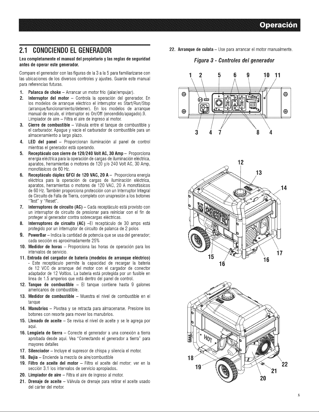
2.1 CONOCiENDOELGENERADOR
Lea compietamenteel manual delpropietarioy las regiasdeseguridad
antes de operar este generador.
Compareel generadorcon lasfiguras de la 3 a la 5 para familiarizarsecon
las ubicaciones de los diversos controles y ajustes. Guardeeste manual
para referenciasfuturas.
1. Palanca de choke- Arrancar un motor frio (jalar/empujar).
2. Interruptor del motor - Controla la operacbn del generador.En
los modelos de arranque electrico el interruptor es Start!Run/Stop
(arranque/funcionamiento/detener).En los modelos de arranque
manualde recule, el interruptor es On/Off (encendido/apagado).9.
Limpiadorde aire - Filtra el aire de ingresoal motor.
3. Cierre de combustible- Va_lvulaentre el tanque de combustible y
el carburador.Apague y vacie el carburador de combustible para un
almacenamientoa largo piazo.
4. LED del panel- Proporcionan iluminacbn al panel de control
mientras el generadoresta,operando.
5. Receptaculo concierre de 120/240 Volt AC,30 Amp- Proporciona
energiaelectricapara la operaciondecargas de iluminacbn electrica,
aparatos,herramientaso motores de 120 y/o 240 Volt AC, 30 Amp,
monofasicos de60 Hz.
6. Receptaculo duplex GFCI de 120 VAC, 20 A- Proporcionaenergia
electrica para la operacbn de cargas de iluminacbn electrica,
aparatos, herramientas o motores de 120 VAC, 20 A monofasicos
de 60 Hz.Tambienproporcionaproteccion con un lnterruptor Integral
de Circuitode Fallade Tierra, completo con unapresiona los botones
"Test" y "Reset".
7. Interruptoresde circuito(AC)- Cadarecepta_cu]oesta provistocon
un interruptor de circuito de presionar para reiniciar con el fin de
proteger al generadorcontra sobrecargaselectricas.
8. Interruptoresde circuito (AC) -El receptaculo de 30 amps esta.
protegido por un interruptor de circuito de palanca de 2 polos
9. PowerBar-Indica la cantidadde potenciaque se usa del generador;
cada seccion es aproximadamente25%
10. Medidor de betas - Proporciona las horas de operacion para los
intervalos de servicio.
11. Entrada del cargador de bateria (modelos de arranque electrico)
- Este receptaculo permite la capacidad de recargar la bateria
de 12 VCC de arranque del motor con el cargador de conector
adaptadorde 12 Voltios. La bateria esta protegidapot un fusible en
linea de 1.5 amperios que esta,dentro del panel de control.
12. Tanque de combustible - El tanque contiene hasta 9 galones
americanosde combustible.
13. Medidor de combustible- Muestra el nivel de combustible en el
tanque
14. Manubrios - Pivotea y se retracta para almacenarse. Presionelos
botones con resorte paramover los manubrios.
15. Llenade de aceite - Se revisa el nivel de aceitey sele agrega por
aqui.
16. Lengiieta de tierra - Conecte el generadora una conexbn a tierra
aprobada desde aqui. Yea "Conectando el generador a tierra" para
mayores detalles
17. Silenciador -Incluye el supresor de chispa y silencia el motor.
18. Bujia - Enciendela mezcla de aire/combustible
lg. Filtro de aceite del motor - Filtra el aceite del motor; ver en la
seccion 3.1 los intervalos de servicio apropiados.
28. Limpiader de aire - Filtra el aire de ingreso al motor.
21. Drenaje de aceite - Va.lvulade drenaje para retirar el aceite usado
del ca.rterdel motor.
22. Arranque de culata- Usepara arrancarel motor manualmente.
Figura 3 - Controles del generador
1 2 5 6 9 10 11
r
@
@
3 4 7 8 4
12
13
15
16
17
16
18
2O
22
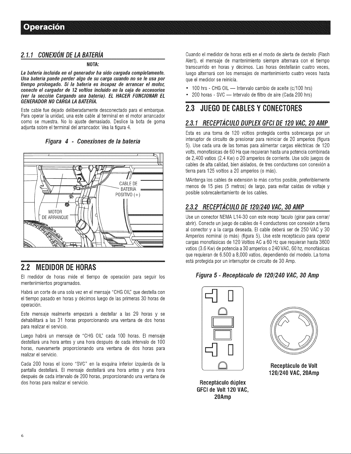
2.1.1CONEXlONDELABATERiA
NOTA:
La bateria incluida en el generador ha sido cargada completamente.
Una bateria puede perder algo de su carga cuando no se le usa por
tiempo prolongado. Si la bateria es incapaz de arrancar el motor,
conecte el cargador de 12 voltios incluido en la caja de accesorios
(ver la seccion Cargando una bateria). EL HACER FUNClONAREL
GENERADORNO CARGALA BATER/A.
Este cable fue dejado deliberadamentedesconectadopara el embarque.
Paraoperar la unidad, una este cable al terminal en el motor arrancador
como se muestra. No Io ajuste demasiado. Deslice la bota de goma
adjunta sobreel terminal del arrancador.Veala figura 4.
Figura 4 - Conexiones de la bateria
_%\\ _ j,._ __ CABLEDE
_:2_/ / _ ....BATERIA
_' / _ _ POSIT!VO(+)
2.2 MEDIDORDE HORAS
El medidor de horas mide el tiempo de operacbn para seguir los
mentenimientosprogramados.
Habraun corte de una sola vez en el mensaje "OHGOIL:'quedestella con
el tiempo pasadoen horasy decimos luego de las primeras 30 horasde
operacion.
Este mensaje realmente empezara,a destellar alas 29 horas y se
dehabilitara alas 31 horas proporcionando una ventana de dos horas
para realizarel servicio.
Luego habra un mensaje de "CHG OIL:'cada 100 horas. El mensaje
destellara una hora antes y una hora despues de cada intervalo de 100
horas, nuevamente proporcionando una ventana de dos horas para
realizarel servicio.
Cada 200 horas el icono "SVC" en la esquina inferior izquierda de la
pantalla destellara. El mensaje destellara,una hora antes y una hora
despues de cada intervalo de 200 horas, proporcionandouna ventanade
dos horas para realizarel servicio.
Cuandoel medidor de horas estaen el modo de alerta de destello (Flash
Alert), el mensaje de mantenimiento siempre alternara con el tiempo
transcurrido en horas y decimos. Las horas destellara.ncuatro veces,
luego alternara con los mensajes de mantenimientocuatro veces hasta
queel medidor se reinicia.
• 100 hrs - CHGOIL -- Intervalocambio de aceite (c/100 hrs)
• 200 horas - SVC-- Intervalo de filtro de aire (Cada200 hrs)
2.3 JUEGO DE CABLESY CONECTORES
2.3.1 RECEPT,4CULODUPLEXGFC/DE 120 VAC,20 AMP
Esta es una toma de 120 voltios protegida contra sobrecarga por un
interuptor de circuito de presionar para reiniciar de 20 amperios (figura
5). Use cada una de las tomas para alimentar cargas electricas de 120
volts, monofasicas de 60 Haque requieranhastauna potenciacombinada
de 2,400 vatios (2.4 Kw) o 20 amperios de corriente. Usesolo juegos de
cablesde alta calidad, bien aislados,de tres conductores con conexbn a
tierra para 125 voltios a 20 amperios (o mas).
MAntengalos cables de extensbn Io mas cortos posible, preferiblemente
menDsde 15 pies (5 metros) de largo, para evitar caidas de voltaje y
posiblesobrecalentamientode los cables.
2.3.2 RECEPTACULODE 120/240 VAC,30 AMP
Useun conector NEMAL14-30 con este recep'taculo (girar para cerrar/
abrir). Conecteun juego de cablesde 4 conductores con conexion a tierra
al conector y a la carga deseada.El cable debera ser de 250 VAC y 30
Amperios nominal (o mas) (figura 5). Useeste receptaculopara operar
cargas monofasicas de 120 Voltios AC a 60 Hz que requieranhasta 3600
vatios (3.6 Kw) de potenciaa 30 amperios o 240 VAC,60 hz, monofasicas
querequierande 6.500 a 8,000 vatios, dependiendodel modelo. La toma
esta.protegidapor un interruptor de circuito de 30 Amp.
Figura 5 - Receptaculo de 120/240 VAC, 30 Amp
Receptaculo duplex
GFCIde Volt 120 VAC,
20Amp
Receptaculo de Volt
120/240 VAC, 20Amp
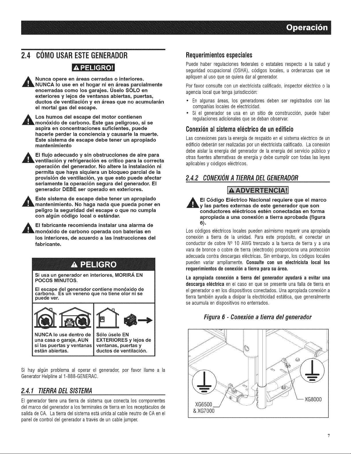
2.4 C6MOUSARESTE6ENERADOR
,_ Nunca opere en _reas cetradas o interiotes.
NUNCA Io use en el hogar ni en _reas parcialmente
encerradas come los garajes. Uselo SOLO en
exteriores y lejos de ventanas abiertas, puertas,
ductos de ventilaci6n yen _reas que no acumular_n
el mortal gas del escape.
,_Los humos del escape del motor contienen
mon6xido de carbono. Este gas peligroso, si se
aspira en concentraciones suficientes, puede
hacerle perder la conciencia y causarle la muerte.
Este sistema de escape debe tenet un apropiado
mantenimiento
,_EI flujo adecuado y sin obstrucciones de aire para
ventilaci6n y refrigeraci6n es crftico para la correcta
operaci6n del generador. No altere la instalaci6n ni
permita que haya siquiera un bloqueo parcial de la
provisi6n de ventilaci6n, ya que esto puede afectar
seriamente la operaci6n segura del generador. El
generador DEBE set operado en exteriores.
,_ Este sistema de escape debe tenet un aptopiado
mantenimiento. No haga nada que pueda poner en
peligro la seguridad del escape o que no cumpla
con alg_n c6digo local o est_ndar.
,_EI fabricante recomienda instalar una alarma de
mon6xido de carbono operada con baterfas en
los interiores, de acuerdo alas instrucciones del
fabricante.
Si usa un generador en interiotes, MORIRA EN
POCOS MINUTES.
El escape del generador contiene mon6×ido de
carbono. Es un veneno que no tiene olor ni se
puede vet.
NUNCA Io use dentro de
una casa o garaje, AUN
si las puertas y ventanas
est_n abiertas.
S61o _seio EN
EXTERIORES y lejos de
ventanas, puettas y
ductoe de ventilaci6n.
Si hay algun problema al operar el generador, por favor Name a la
GeneratorHelplineal 1-888-GENERAC.
2.4.1 T/ERRA#EL SlSTEMA
El generadortiene una tierra de sistema que conecta los componentes
del marco del generadora los terminales de tierra en los receptaculosde
salida de CA. La tierra del sistema esta unida al cable neutro de CA en el
panel de control del generadora traves de un cable jumper.
Requerimient0sespeciales
Puede haber regulaciones federales o estatales respecto a la salud y
seguridad ocupacional (OSHA),codigos locales, u ordenanzas que se
apliquenal use que se quieradar al generador.
Per favor consulte con un electricista calificado, inspector electrico o la
agencialocal que tenga jurisdiccion:
* En algunas areas, los generadores deben ser registrados con las
compafiias locales de electricidad.
* Si el generador se usa en un sitio de construccion, puede haber
regulacionesadicionalesque se debanobservar.
C0nexi6nal sistemaelectric0deunedifici0
Las conexionespara la energiade respaldo en el sistema electrico de un
edificio deberanser realizadasper un electricista calificado. La conexion
debe aislar la energia del generadorde la energia del servicio publico y
otras fuentes alternativas de energiay debe cumplir con todas las leyes
aplicablesy codigos electricos.
2.4.2 CONEXlONA TIERRADELGENERADOR
,i_EI C6digo EI6ctrico Nacional requiere que el marco
y las partes externas de este generadot que son
conductores el_ctricos est_n conectadas en forma
apropiada a una conexi6n a tietta aprobada (figura
6).
Los codigos electricos locales pueden asimismo requerir una apropiada
conexion a tierra de la unidad. Para este proposito, el conectar un
conductor de cobre NO10 AWG trenzado a la tuerca de tierra y a una
vara de bronce o cobre de tierra (electrodo) proporciona una proteccion
adecuadacontra descargas electricas. Sin embargo, los codigos locales
pueden variar ampliamente. Consulle con un eleclricista local los
requerimientesde conexi6na tierra para su ;ire&
La apropiada c0nexi6n a tierra del generad0r ayudar;i a evitar una
descargaelectrica en el cas0 en que se presenteuna faNade tierra en
el generad0r0 en 10sdisp0sitiv0s c0nectad0s. Una apr0piadac0nexi6n a
tierra tambien ayuda a disipar la electricidad estatica, que generalmente
se acumula en disp0sitiv0s no enterrad0s.
Figura 6 - Conexiona tierra del generador
& XG7000
XG8000
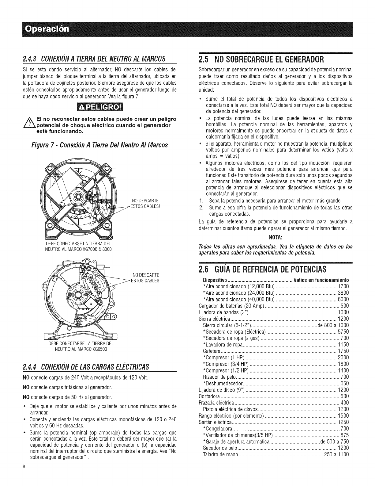
2.4.3 CONEX/ONA T/ERRADELNEUTROAL MARCOS
Si se esta dando servicio al alternador, NO descarte los cables del
jumper blanco del bloque terminal a la tierra del alternador,ubicada en
la portadora de cojinetes posterior.Siempre aseguresede que los cables
esten conectados apropiadamenteantes de usar el generadorluego de
que se hayadado servicio al generador.Veala figura 7.
El no reconectar estos cables puede crear un peligro
potential de choque el6ctrico cuando el generador
est6 funcionando.
Figura 7 - Conexibn A Tierra De/Neutro A/Marcos
DEBECONECTARSELA TIERRADEL
NEUTROALMARCOXGT000& 8000
NODESCARTE
_ NODESCARTE
DEBECONECTARSELATIERRADEL
NEUTROAL MARCOXG6500
2.4.4 CONEXlONBELASCARGASEL CTRICAS
NO conecte cargasde 240 Volt a receptaculosde 120 Volt.
NO conecte cargastrifasicas al generador.
NO conecte cargasde 50 Hz al generador.
• Deje que el motor se estabilice y caliente por unos minutos antes de
arrancar.
• Conecte y enciendalas cargas electricas monofa.sicasde 120 o 240
voltios y 60 Hz deseadas.
• Sume la potencia nominal (op amperaje) de todas las cargas que
seran conectadasa la vez. Estetotal no debera ser mayor que (a) la
capacidad de potencia y corriente del generadoro (b) la capacidad
nominal del interruptor del circuito que suministrala energia.Vea "No
sobrecargueel generador".
2.5 NO SOBRECARGUEELGENERADOR
Sobrecargarun generadoren excesode su capacidadde potencianominal
puede traer como resultado dahos al generador y a los dispositivos
electricos conectados. Observe Io siguiente para evitar sobrecargar la
unidad:
Sume el total de potencia de todos los dispositivos electricos a
conectarsea la vez. Este total NOdebera,ser mayor que la capacidad
de potenciadel generador.
• La potencia nominal de las luces puede leerse en las mismas
bombillas. La potencia nominal de las herramientas, aparatos y
motores normalmente se puede encontrar en la etiqueta de datos o
calcomaniafijada en el dispositivo.
• Si el aparato,herramientao motor no muestranla potencia,multiplique
voltios pot amperios nominales para determinar los vatios (volts x
amps = vatios).
• Algunos motores electricos, como los del tipo induccion, requieren
alrededor de tres veces mas potencia para arrancar que para
funcionar.Estetransitorio depotenciadura solo unos pocos segundos
al arrancar tales motores. Asegurese de tener en cuenta esta alta
potencia de arranque al seleccionar dispositivos electricos que se
conectaran al generador.
1. Sepa la potencia necesariapara arrancar el motor ma.sgrande.
2. Sume a esa cifra la potencia de funcionamiento de todas las otras
cargas conectadas.
La guia de referencia de potencias se proporciona para ayudarle a
determinarcua.ntositems puedeoperar el generadoral mismo tiempo.
NOTA:
Todas /as cifras son apreximadas. Vea la etiqueta de datos en los
aparatos para saber los requerimientos de poteneia.
2.6 GUiADEREFRENOIADEPOTENCIAS
Dispositivo ............................................... Vatiosen funcionamiento
*Aire acondicionado(12,000 Btu) ............................................ 1700
*Aire acondicionado(24,000 Btu) ............................................ 3800
*Aire acondicionado(40,000 Btu) ............................................ 6000
Cargadorde baterias (20 Amp)...................................................... 500
Lijadorade bandas(3") ............................................................... 1000
Sierra electrica............................................................................. 1200
Sierra circular (6-1/2") ................................................ de 800 a 1000
*Secadora de ropa (Electrica) .................................................. 5750
*Secadora de ropa (a gas) ......................................................... 700
*Lavadora de ropa.................................................................... 1150
Cafetera.................................................................................... 1750
*Oompresor (1 HP) .................................................................. 2000
*Oompresor (3/4 HP) ............................................................... 1800
*Oompresor (1/2 HP) ............................................................... 1400
Rizador de pelo........................................................................... 700
*Deshumedecedor...................................................................... 650
Lijadora de disco (9") .................................................................. 1200
Oortadora...................................................................................... 500
Frazadaelectrica............................................................................ 400
Pistola electricade clavos......................................................... 1200
Rango electrico (pot elemento).................................................... 1500
Sarten electrica............................................................................ 1250
*Congeladora ....................................................................... 700
*Ventilador de chimenea(3/5HP)................................................ 875
*Garaje de apertura automatica.................................... de 500 a 750
Secador de pelo........................................................................ 1200
Taladrode mano.............................................................. 250 a 1100
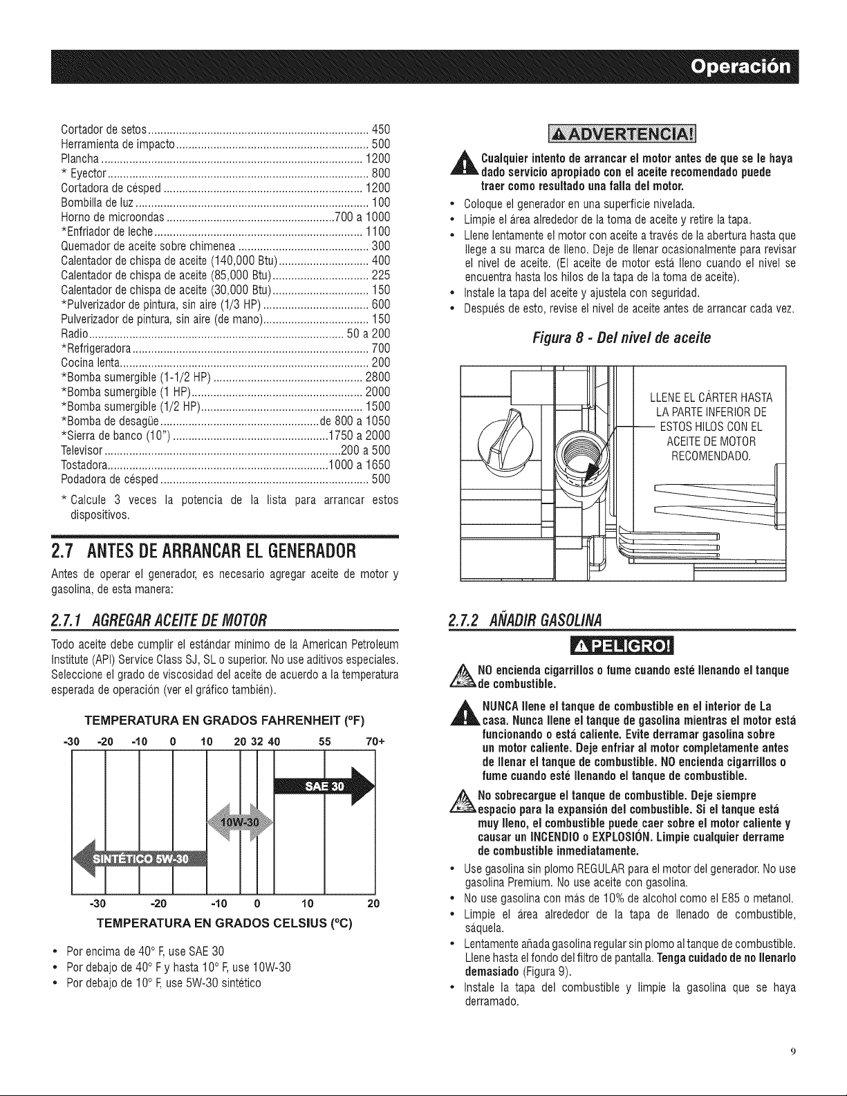
Cortadordesetos.......................................................................450
Herramientadeimpacto..............................................................500
Plancha....................................................................................1200
* Eyector....................................................................................800
Cortadoradecesped................................................................1200
Bombilladeluz...........................................................................100
Homodemicroondas......................................................700a1000
*Enfriadordeleche...................................................................1100
Quemadordeaceitesobrechimenea..........................................300
Calentadordechispadeaceite(140,000Btu).............................400
Calentadordechispadeaceite(85,000Btu)...............................225
Calentadordechispadeaceite(30,000Btu)...............................150
*Pulverizadordepintura,sinaire(1/3HP)..................................600
Pulverizadordepintura,sinaire(demano)..................................150
Radio..................................................................................50a200
*Refrigeradora............................................................................700
Cocinalenta................................................................................200
*Bombasumergible(1-1/2HP)................................................2800
*Bombasumergible(1HP).......................................................2000
*Bombasumergible(1/2HP)....................................................1500
*BombadedesagiJe...................................................de800a1050
*Sierradebanco(10")..................................................1750a2000
Televisor............................................................................200a500
Tostadora.......................................................................1000a1650
Podadoradecesped...................................................................500
* Calcule 3 veces la potencia de la lista para arrancar estos
dispositivos.
2.7 ANTESDEARRANCARELGENERADOR
Antes de operar el generador,es necesario agregar aceite de motor y
gasolina,de estamanera:
2.7.1 ASRESARACEITEDE MOTOR
Todo aceite debe cumplir el estandar minimo de la American Petroleum
Institute(API) Service Class SJ, SL o superior.Nouse aditivosespeciales.
Seleccioneel grado de viscosidad del aceite de acuerdoa la temperatura
esperadadeoperacion (ver el gra.ficotambien).
TEMPERATURA EN GRADOS FAHRENHEIT (OF)
=30 =20 =10 0 10 20 32 40 55 70+
=30" =20 ' =10 0 10 20
TEMPERATURA EN GRADOS CELSIUS (°C)
• Por encima de 40° F,use SAE 30
• Por debajo de 40° Fy hasta 10° F,use 10W-30
• Por debajo de 10° F,use 5W-30 sintetico
,_ Cuaiquierintent{)de el motor antes de le
arrancar
que
8e
baya
dado servicio apropiado conel aceite recomendado puede
truer come resultadounafalla del motor.
• Coloque el generadoren una superficie nivelada.
• Limpie el a_reaalrededor de latoma de aceite y retire la tapa.
• Llenelentamenteel motor con aceitea traves de la abertura hasta que
liege a su marca de lien& Deje de Ilenarocasionalmentepara revisar
el nivel de aceite. (El aceite de motor esta_Ileno cuando el nivel se
encuentrahasta los hilos de la tapa de la toma de aceite).
• Instale la tapa del aceite y ajustela con seguridad.
• Despuesde esto, revise el nivel de aceiteantes de arrancar cadavez.
Figura 8 -Oel nivel de aceite
m
!_ LLENEELCARTERHASTA
LA PARTEINFERIORDE
-- ESTOSHILOSCONEL
ACEITEDE MOTOR
i
2.7.2 A[IAOIR8ASOLINA
z_N0 encienda cigarrilloso fume cuandoeste Ilenando el tanque
de combustible.
,_ NUNCAIlene el tanque de combustibleen el interior de La
casa. Nunca Ilene el tanque de gasolina mientras el motoresta
funcionando o esta caliente.Evite derramar gasolina sobre
un motor caliente. Deje enfriar al motorcompletamenteantes
de Ilenar el tanque de combustible.NOencienda cigarrillos o
fume cuandoeste Ilenandoel tanque de combustible.
No sobrecargue el tanque de combustible.Deje siempre
espacio para la expansi6n del combustible.Si el tanque esta
muy Ileno, el combustiblepuede caer sobre el motor calientey
causar un INOENDI0o EXPLOSION.Limpie cualquierderrame
de combustibleinmediatamente.
• Usegasolina sin plomo REGULARpara el motor del generador.No use
gasolina Premium.No use aceitecon gasolina.
• No use gasolina con mas de 10%de alcohol como el E85o metanol.
• Limpie el area alrededor de la tapa de Ilenado de combustible,
sa_quela.
• Lentamenteafiadagasolinaregularsin plomo altanquede combustible.
Llenehastaelfondo del filtro depantalla.Tengacuidadode noIlenarlo
demasiado (Figura9).
• Instale la tapa del combustible y limpie la gasolina que se haya
derramado.
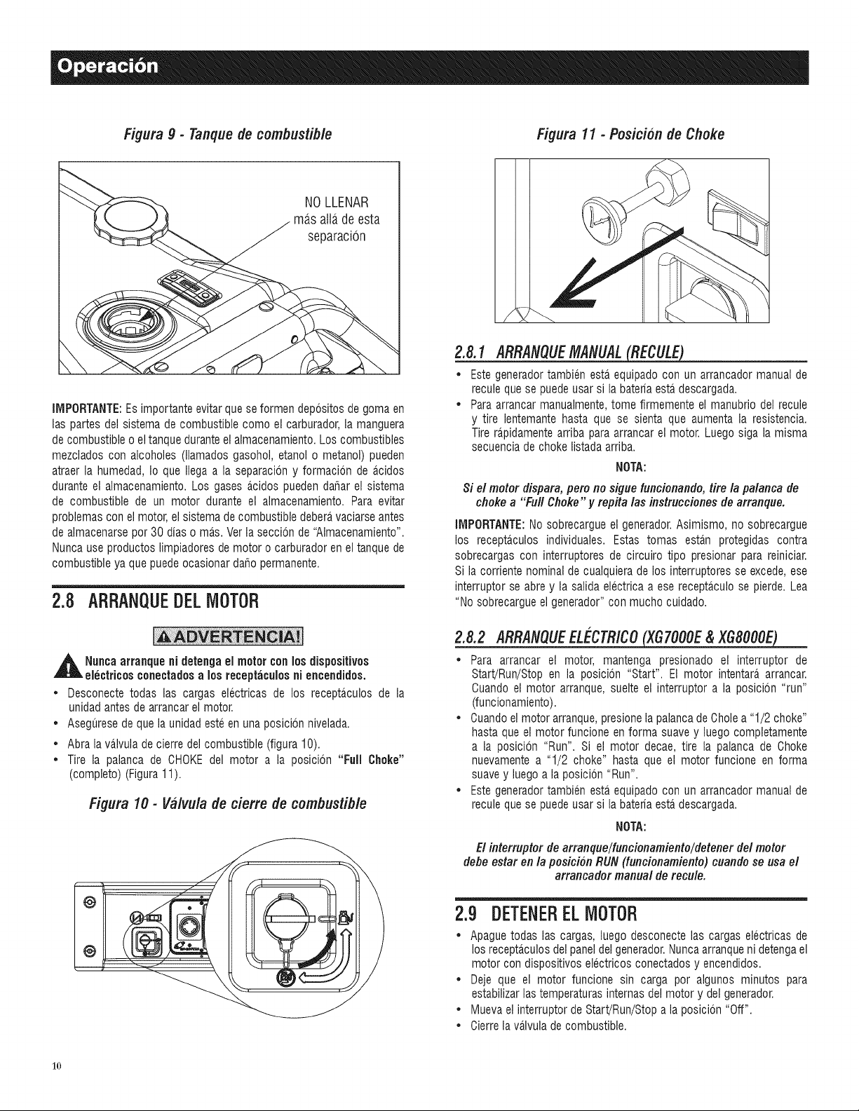
Figura9 - Tanquede combustible
NOLLENAR
ma,s atlade esta
separacion
IMPORTANTE:Esimportante evitar que se formen depositosde goma en
las partes del sistema de combustible como el carburador,la manguera
de combustibleo eltanque durante el almacenamiento.Los combustibles
mezclados con alcoholes (llamados gasohol, etanol o metanol) pueden
atraer la humedad, Io que Ilega a la separacion y formacion de a_cidos
durante el almacenamiento. Los gases acidos pueden dahar el sistema
de combustible de un motor durante el almacenamiento. Para evitar
problemascon el motor, el sistema de combustible debera,vaciarse antes
de almacenarsepor 30 dias o mas. Ver la seccion de "AImacenamiento".
Nuncause productos limpiadores de motor o carburadoren el tanque de
combustible ya que puedeocasionar daho permanente.
2.B ARRANQUEDELMOTOR
_ll uncaarranque ni detenga el motor con los dispositivos
electricosconectadusa los receptaculosni encendidos.
* Desconecte todas las cargas electricas de los recepta,culos de la
unidadantes de arrancar el motor.
* Aseguresede que la unidad esteen una posicion nivelada.
* Abra la valvula de cierre del combustible (figura 10).
* Tire la palanca de CHOKEdel motor a la posicion "Full Choke"
(completo) (Figura11).
Figura 10- Va/vulade derre de combustible
/
2.8.1 ARRANQUEMANUAL
* Este generadortambien esta equipado con un arrancador manual de
recule que se puede usar si la bateria esta descargada.
* Para arrancar manualmente,tome firmemente el manubrio del recule
y tire lentemante hasta que se sienta que aumenta la resistencia.
Tire rapidamentearriba para arrancar el motor. Luego siga la misma
secuenciade choke listadaarriba.
NOTA:
Si el motor dispara, pero no sigue funcionando, tire la palanca de
choke a "Full Choke" y repRa las instruccionesde arranque.
IMPORTANTE:No sobrecargue el generador.Asimismo, no sobrecargue
los recepta_culosindividuales. Estas tomas esta,n protegidas contra
sobrecargas con interruptores de circuiro tipo presionar para reiniciar.
Si la corriente nominalde cualquiera de los interruptores se excede, ese
interruptor se abre y la salida electrica a ese recepta,culo se pierde. Lea
"No sobrecargueel generador"con mucho cuidado.
2.8.2 ARRANQUEEL_'CTRICO___
* Para arrancar el motor, mantenga presionado el interruptor de
Start!Run/Stop en la posicion "Start". El motor intentara arrancar.
Cuando el motor arranque, suelte el interruptor a la posicion "run"
(funcionamiento).
* Cuandoel motor arranque,presionela palancade Chole a "1/2 choke"
hasta que el motor funcione en forma suave y luego completamente
a la posicion "Run". Si el motor decae, tire la palanca de Choke
nuevamentea "1/2 choke" hasta que el motor funcione en forma
suavey luego a la posicion "Run".
* Este generadortambien esta equipado con un arrancador manual de
recule que se puede usar si la bateria esta.descargada.
NOTA:
El interruptor de arranque/funcionamiento/detener del motor
defle estar en la posicion RUN (funcionamiento) cuando se usa el
arrancador manual de recule.
2.9 DETENEREL MOTOR
* Apaguetodas las cargas, luego desconecte las cargas electricas de
los recepta_culosdel paneldel generador.Nuncaarranqueni detengael
motor con dispositivos electricos conectados y encendidos.
* Deje que el motor funcione sin carga por algunos minutos para
estabilizarlas temperaturasinternas del motor y del generador.
* Muevael interruptor de Start/Run/Stopa la posicion "Off".
* Cierre la va.lvulade combustible.
1o
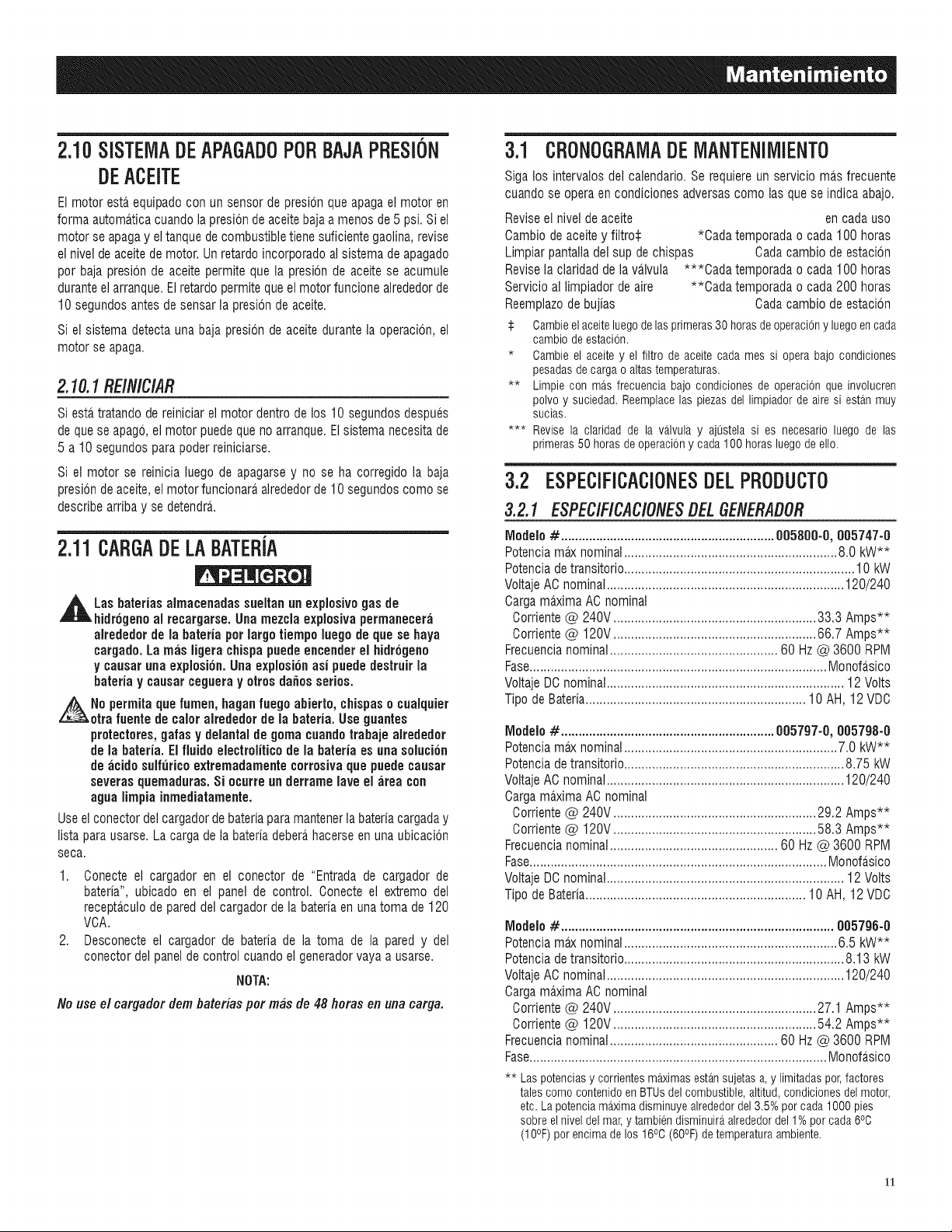
2.10SISTEMADEAPAGADOP0RBAJAPRESION
DEACEITE
El motor esta equipado con un sensor de presionque apagael motor en
forma automatica cuandola presion de aceitebaja a menos de 5 psi. Si el
motor se apagay eltanque de combustible tienesuficiente gaolina, revise
el nivel de aceite de motor. Unretardoincorporado al sistema de apagado
por baja presion de aceite permite que la presion de aceite se acumule
duranteelarranque.El retardo permite queel motor funcione alrededorde
10 segundos antes de sensarla presion de aceite.
Si el sistema detecta una baja presion de aceite durante la operacion, el
motor se apaga.
2.10.1 REIN/C/AR
Siesta tratando de reiniciar el motor dentro de los 10 segundos despues
de quese apago, el motor puedeque no arranque.El sistema necesitade
5 a 10 segundospara poder reiniciarse.
Si el motor se reinicia luego de apagarsey no se ha corregido la baja
presbn de aceite,el motor funcionara,alrededorde 10 segundos como se
describearriba y se detendra..
2.11CARGADE LA BATEBIA
,_Las baterias almacenadas sueltan un explosivo gas de
hidr6genoal recargarse. Una mezcla explosiva permanecer;i
alrededor de la bateria pot largo tiempo luego de que se haya
cargado.La re;is ligerachispapuedeencender el hidr6geno
y causaruna expiosi6n. Una explosion asi puede destruirla
bateria y causar cegueray otrosda_osserios.
No permita que lumen, haganfuego abierto, chispaso cualquier
otrafuente de calor alrededor de la bated& Use guantes
protectores,galas y delantal de goma cuandotrabaje alrededor
de la bated& El fluidoelectrolitico de la bateria es una solucion
de acido sulfuricoextremadamente corrosivaque puedecausar
severasquemaduras. Si ocurre un derramelave el ;irea con
agua limpia inmediatamente.
Useel conector del cargadorde bateriapara mantenerla bateriacargaday
lista para usarse.La carga de la bateria debera,hacerse en una ubicacion
seca.
1. Oonecte el cargador en el conector de "Entrada de cargador de
bateria", ubicado en el panel de control. Oonecte el extremo del
recepta.culode pared del cargador de la bateria en una toma de 120
VOA.
2. Desconecte el cargador de bateria de la toma de la pared y del
conector del panel de control cuando el generadorvayaa usarse.
NOTA:
No use el cargador dem bateriasper mas de 48 horas en una carga.
3.1 CBONOGBAIV]ADE MANTENIMIENTO
Siga los intervalos del calendario. Se requiereun servicio mas frecuente
cuando se operaen condiciones adversascomo las que se indica abajo.
Revise el nivel de aceite en cada uso
Oambio de aceite y filtro$ *Cada temporada o cada 100 horas
Limpiar pantalla del sup de chispas Cada cambio de estacion
Revise la claridad de la valvula ***Cada temporada o cada 100 horas
Servicio al limpiador de aire **Oada temporada o cada 200 horas
Reemplazo de bujias Cada cambio de estacion
:i: Cambieel aceite luego de las primeras 30 horas de operaci0n y luego en cada
cambio de estaci0n.
* Cambie el aceite y el filtro de aceite cada mes si opera bajo condiciones
pesadas de carga o altas temperaturas.
** Limpie con mas frecuencia bajo condiciones de operacion que involucren
polvo y suciedad. Reemplacelas piezas del limpiador de aire si estan muy
sucias.
*** Revise la claridad de la valvula y ajustela si es necesario luego de las
primeras 50 horas de operacion y cada 100 horas luego de ello.
3.2 ESPECIFICACIONESDELPBODUCTO
3.2.1 ESPECiFICACiONESDELGENERADOR
Modelo # ............................................................. 005800-0, 005747-0
Potenciam_ nominal............................................................. 8.0 kW**
Potenciadetransitorio.................................................................. 10 kW
VoltajeAC nominal.................................................................... 120/240
Carga maxima AC nominal
Corriente @ 240V .......................................................... 33.3 Amps**
Oorriente@ 120V.......................................................... 66.7 Amps**
Frecuencianominal................................................ 60 Hz @ 3600 RPM
Fase..................................................................................... Monofa_sico
VoltajeDO nominal.................................................................... 12 Volts
Tipo de Bateria............................................................... 10 AH, 12 VDC
Modelo # ............................................................. 005797-0, 005798-0
Potenciam_ nominal............................................................. 7.0 kW**
Potenciadetransitorio............................................................... 8.75 kW
VoltajeAC nominal.................................................................... 120/240
Carga maxima AC nominal
Corriente @ 240V .......................................................... 29.2 Amps**
Oorriente@ 120V.......................................................... 58.3 Amps**
Frecuencianominal................................................ 60 Hz @ 3600 RPM
Fase..................................................................................... Monofa_sico
VoltajeDO nominal.................................................................... 12 Volts
Tipo de Bateria............................................................... 10 AH, 12 VDC
Modelo # .............................................................................. 005796-0
Potenciam_ nominal............................................................. 6.5 kW**
Potenciadetransitorio............................................................... 8.13 kW
VoltajeAC nominal.................................................................... 120/240
Carga maxima AC nominal
Oorriente@ 240V .......................................................... 27.1 Amps**
Oorriente@ 120V.......................................................... 54.2 Amps**
Frecuencianominal................................................ 60 Hz @ 3600 RPM
Fase..................................................................................... Monofa.sico
** Las potencias y corrientes maximas estan sujetas a, y limitadas por, factores
tales como contenido en BTUsdel combustible, altitud, condiciones del motor,
etc. La potencia maxima disminuye alrededordel 3.5% por cada 1000 pies
sobre elnivel del mar, y tambien disminuira alrededordel 1% por cada6°0
(10°F) por encima de los 16°C (60°F) de temperaturaambiente.
11
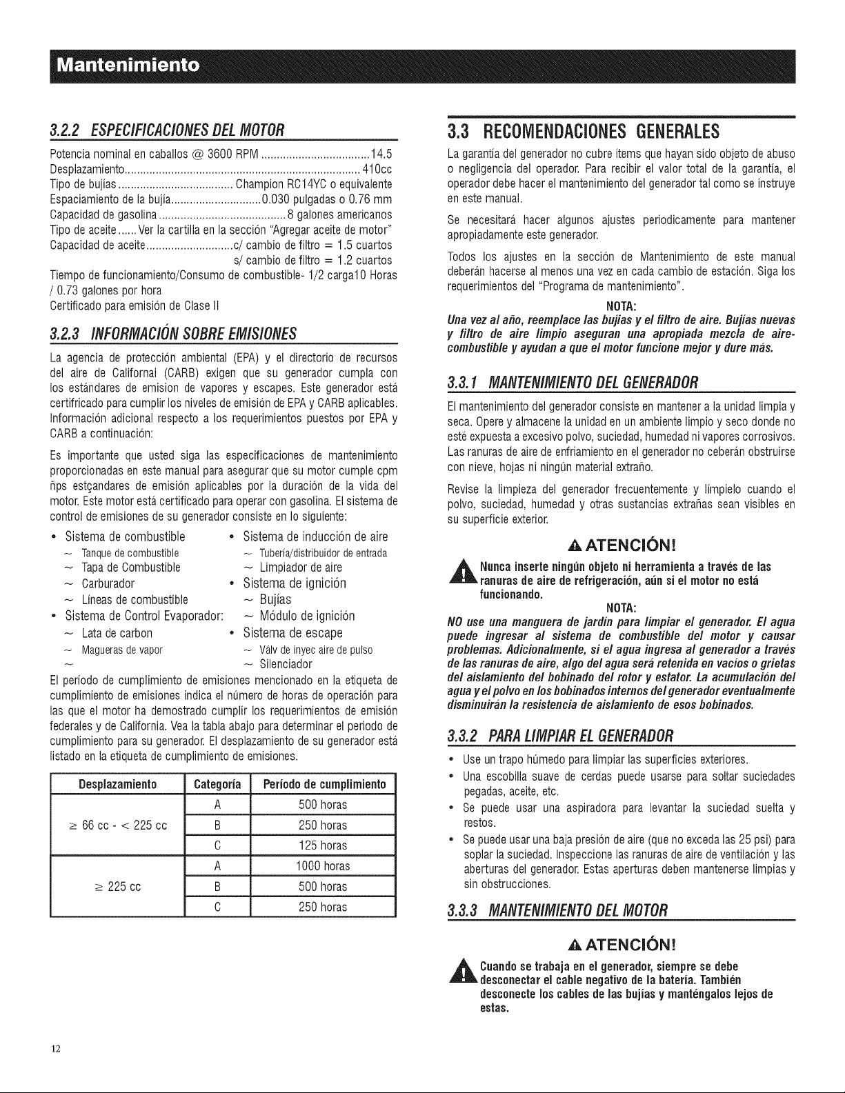
3.2.2 ESPEC/F/CAC/ONESBELMOTOR
Potencianominal en caballos @ 3600 RPM................................... 14.5
Desplazamiento............................................................................ 410cc
Tipo de bujias..................................... ChampionRC14YCo equivalente
Espaciamientode la bujia............................. 0.030 pulgadas o 0.76 mm
Capacidadde gasolina......................................... 8 galones americanos
Tipo de aceite......Ver la cartilla en la seccion "Agregaraceitede motor"
Capacidadde aceite............................c/cambio de filtro = 1.5 cuartos
s/cambio de filtro = 1.2 cuartos
Tiempo de funcionamiento/Consumode combustible- 1/2 cargal0 Horas
/ 0.73 galones por hora
Certificado paraemision de ClaseII
3.2.3 /NFORMAC/ONSOBREEM/SlONES
La agencia de proteccion ambiental (EPA) y el directorio de recursos
del aire de Californai (CARB) exigen que su generador cumpla con
los estandares de emision de vapores y escapes. Este generador esta
certifricado para cumplir los niveles de emision de EPAy CARBaplicables.
Informacion adicional respecto a los requerimientos puestos por EPA y
CARBa continuacion:
Es importante que usted siga las especificaciones de mantenimiento
proporcionadasen estemanual para asegurar que su motor cumple cpm
tips estgandares de emision aplicables por la duracion de la vida del
motor. Este motor estacertificado para operar con gasolina.Elsistema de
control de emisiones de su generadorconsiste en Io siguiente:
* Sistema de combustible * Sistema de induccion de aire
- Tanquedecombustible - Tuberia/distribuidorde entrada
Tapade Combustible - Limpiador deaire
Carburador • Sistema de ignicion
Lineas de combustible _ Bujias
, Sistema de Control Evaporador: - Modulo de ignicion
Lata de carbon • Sistema de escape
- Maguerasde vapor - VANdeinyecairedepulso
-- Silenciador
El periodo de cumplimiento de emisiones mencionado en la etiqueta de
cumplimiento de emisionesindica el numero de horas de operacionpara
las que el motor ha demostrado cumplir los requerimientos de emision
federalesy de California.Veala tabla abajo para determinarel periodo de
cumplimiento para su generador.El desplazamientode su generadoresta,
listado en la etiquetade cumplimientode emisiones.
Desplazamiento Categoria Periodo de cumplimiento
A 500 horas
_>66 cc- < 225 cc B 250 horas
C 125 horas
A 1000 horas
_>225 cc B 500 horas
C 250 horas
3.3 REC01VlENDACiONESGENERALES
La garantiadel generadorno cubre items quehayan sido objeto de abuso
o negligencia del operador. Para recibir el valor total de la garantia, el
operadordebe hacer el mantenimientodel generadortal como se instruye
en estemanual.
Se necesitara_hacer algunos ajustes periodicamente para mantener
apropiadamenteeste generador.
Todos los ajustes en la seccion de IVlantenimientode este manual
deberanhacerse al menos unavez en cada cambio de estacion.Siga los
requerimientosdel "Programa de mantenimiento".
NOTA:
Una vezal afio, reemplace los flujias y el filtro de aire. Bujias nuevas
y filtro de aire limpio aseguran una apropiada mezcla de aire-
combustib/e y ayudan a que el motor funcione mejor y dure mas.
3.3.1 MANTEN/M/ENTODEL6ENERADOR
Elmantenimientodel generadorconsiste en mantenera la unidadlimpia y
seca. Operey almacenela unidaden un ambientelimpio y seco dondeno
esteexpuestaa excesivopolvo,suciedad,humedadnivapores corrosivos.
Las ranurasde airede enfriamientoen el generadorno cebera.nobstruirse
con nieve, hojas ni ningun materialextrafio.
Revise la limpieza del generador frecuentemente y limpielo cuando el
polvo, suciedad, humedad y otras sustancias extrafias sean visibles en
su superficie exterior.
AATENCION!
,_ Nuncainserte ning0n objetoni herramientaa troves de los
ranurasde aire de refrigeration, aun si el motor no esta
funcionando.
NOTA:
NO use una manguera de jardiu tiara limfliar el generador. El agua
puede ingresar al sistema de combustible del motor y causar
problemas. Adicionalmente, si el agua ingresa al generador a troves
de los ranuras de aire, algo del agua sera retenida en vacios o grietas
del aislamiento del bobinado del rotor y estator. La acumulaci#u del
agua y el polvo en los bobinados intemos del generador eventualmente
disminuiran la resistencia de aislamiento de esos bobinados.
3.3.2 PARAL/MP/ARELGENERADOR
• Use un trapo humedo paralimpiar las superficies exteriores.
• Una escobilla suave de cerdas puede usarse para soltar suciedades
pegadas,aceite,etc.
• Se puede usar una aspiradora para levantar la suciedad suelta y
restos.
• Se puedeusar unabaja prestonde aire (queno excedalas 25 psi) para
soplar la suciedad. Inspeccionelas ranurasde aire de ventilacion y las
aberturas del generador.Estas aperturas debenmantenerselimpias y
sin obstrucciones.
3.3.3 MANTEN/MIENTODELMOTOR
,& ATENCION!
,_l Cuandose trabaja en el generador, siempre se debe
desconectar el cable negativode la bateria. Tambien
desconecte los cables de las bujias y mantengalos lejos de
estas.
12
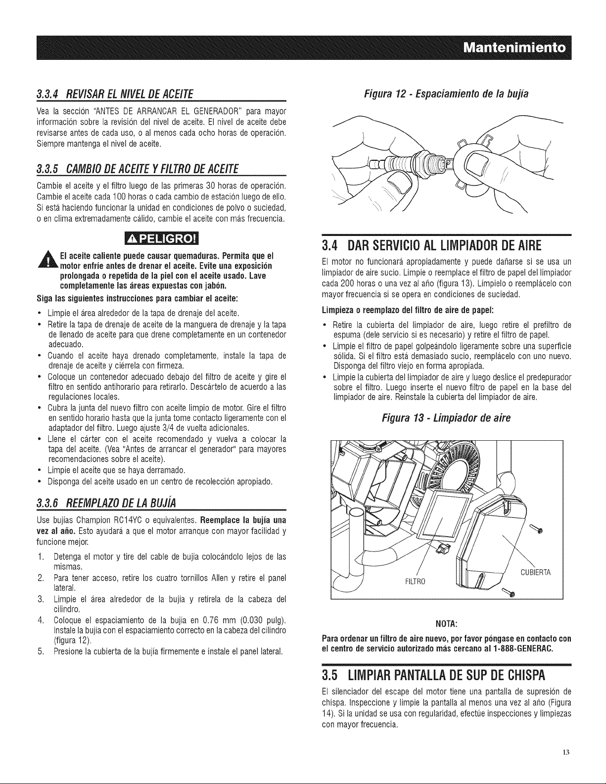
3.3.4 REV/SARELN/VELDEACE/TE
Yea la seccion "ANTES DE ARRANCAREL GENERADOR"para mayor
informacbn sobre la revision del nivel de aceite. El nivel de aceite debe
revisarse antes de cada uso, o al menos cada ocho horas de operacion.
Siempre mantengael nivel de aceite.
3.3.5 CAMBiODEACEITEYF/LTRODEACEITE
Cambie el aceite y el filtro luego de las primeras 30 horas de operacion.
Cambieel aceitecada 100 horaso cadacambio de estacion luegode ello.
Siesta haciendofuncionar la unidad encondiciones de polvo o suciedad,
oen clima extremadamenteca,lido, cambie el aceitecon ma,s frecuencia.
,_EI aceite calientepuede causarquemaduras. Permita que el
motor enfrie antes de drenar el aceite. Evite una exposicion
prolongadao repetida de la piel con el aceite usado. Lave
completamenteins areas expuestas conjabon.
Sign ins siguientes instruccionespara cambiar el aceite:
• Limpie el area alrededorde latapa de drenajedel aceite.
• Retirela tapa de drenajede aceite de la manguera de drenajey la tapa
de Ilenadodeaceite para que drene completamenteen un contenedor
adecuado.
• Cuando el aceite haya drenado completamente, instale la tapa de
drenajede aceitey cierrela confirmeza.
• Coloque un contenedor adecuadodebajo del filtro de aceite y gire el
filtro en sentido antihorario para retirarlo. Desca,rtelo de acuerdo a las
regulacioneslocales.
• Cubra la junta del nuevo filtro con aceite limpio de motor. Gireel filtro
en sentido horario hastaque la juntatome contacto ligeramentecon el
adaptadordel filtro. Luegoajuste 3/4 de vuelta adicionales.
• Llene el carter con el aceite recomendado y vuelva a colocar la
tapa del aceite. (Vea "Antes de arrancar el generador"para mayores
recomendacionessobre el aceite).
• Limpie el aceite que se haya derramado.
• Disponga del aceite usado en uncentro de recoleccbn apropiado.
3.3.6 REEMPLAZODE LABUJiA
Use bujias Champion RC14YCo equivalentes.Reemplaoe la bujia ann
vez al a_o. Esto ayudara a que el motor arranque con mayor facilidad y
funcione mejor.
1. Detengael motor y tire del cable de bujia colocandolo lejos de las
mismas.
2. Para tener acceso, retire los cuatro tornillos Allen y retire el panel
lateral.
3. Limpie el area alrededor de la bujia y retirela de la cabeza del
cilindro.
4. Coloque el espaciamiento de la bujia en 0.76 mm (0.030 pulg).
Instalela bujia con elespaciamientocorrecto enla cabezadel cilindro
(figura 12).
5. Presionela cubierta de la bujia firmemente e instale el panel lateral.
Figura 12 - Espaciamiento de la bujia
3.4 DARSERVICIOALLIMPiADORDEAIRE
El motor no funcionara apropiadamente y puede daharse si se usa un
limpiador de aire sucio. Limpie o reemplaceelfiltro de papel del limpiador
cada 200 horns ouna vez al aho (figura 13). Limpielo o reempla,celo con
mayor frecuencia si se operaen condiciones de suciedad.
Limpiezao reemplazo del filtro de aire de papel:
• Retire la cubierta del limpiador de aire, luego retire el prefiltro de
espuma (dele servicio si es necesario)y retireel filtro de papel.
• Limpie el filtro de papel golpeandololigeramentesobre una superficie
solida. Si el filtro esta demasiadosucio, reemplacelocon uric nuevo.
Disponga del filtro viejo en forma apropiada.
• Limpie la cubierta del limpiador de airey luego desliceel predepurador
sobre el filtro. Luego inserte el nuevo filtro de papel en la base del
limpiador de aire. Reinstalela cubierta del limpiador de aire.
Figura 13 - Limpiador de aire
FILTRO
CUBIERTA
NOTA:
Para ordenarun filtro de aire nuevo, perfavor p6ngaseen contactocon
el centrode servicio autorizado mas cercanoal 1-888-GENERAC.
3.5 LllVlPiARPANTALLADESUPDECHiSPA
El silenciador del escape del motor tiene una pantalla de supresbn de
chispa. Inspeccioney limpie la pantalla al menos una vez al aho (Figura
14). Si la unidad se usa con regularidad,efectueinspeccionesy limpiezas
con mayor frecuencia.
13
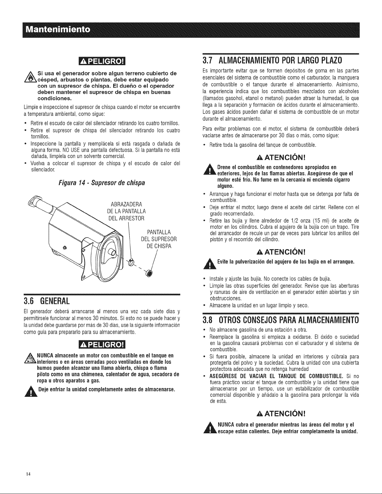
Si usa el generador sobre algun terreno cubierto de
c_sped, arbustos o plantas, debe estar equipado
con un supresor de chispa. El dueho o el operador
deben mantener el supresor de chispa en buenas
condiciones.
Limpie e inspeccioneel supresorde chispa cuando elmotor se encuentre
a temperaturaambiental, como sigue:
• Retireel escudo de calor del silenciador retirandolos cuatrotornillos.
• Retire el supresor de chispa del silenciador retirando los cuatro
tornillos.
• Inspeccione la pantalla y reemplacela siesta_ rasgada o dahada de
algunaforma. NO USEuna pantalla defectuosa.Si la pantalla no esta.
dahada,limpiela con un solvente comercial.
• Vuelva a colocar el supresor de chispa y el escudo de calor del
silenciador.
Figura 14 - 3upreser de chispa
ABRAZADERA
DELA PANTALLA
DELARRESTOR
II PANTALLA
DELSUPRESOR
DECHISPA
3.6 GENERAL
El generador debera arrancarse al menos una vez cada siete dias y
permitirselefuncionar al menos 30 minutos. Si esto no se puedehacer y
la unidaddebe guardarsepor mas de30 dias, use la siguienteinformacion
como guia paraprepararlopara su almacenamiento.
NUNCAalmacente un motor concombustibleen el tanque en
interioreso en ;ireascerradas pocoventiladasen donde los
humospuedenalcanzar unallama abierta, chispa o flama
pilotocomo en una chimenea,calentador de agua, secadora de
ropa u otrosaparatos a gas.
,_1 Deje enfriar la unidad¢ompletamente antes de almacenarse.
3.7 ALMACENAMIENT0P0R LARGOPLAZ0
Es importante evitar que se formen depositos de goma en las partes
esenciales del sistema de combustible como el carburador, la manguera
de combustible o el tanque durante el almacenamiento. Asimismo,
la experiencia indica que los combustibles mezclados con alcoholes
(llamados gasohol, etanol o metanol) pueden atraer la humedad, Io que
Ilega a la separacion y formacion de acidos duranteel almacenamiento.
Los gases acidos puedendahar el sistema de combustible de un motor
durante el almacenamiento.
Para evitar problemas con el motor, el sistema de combustible debera.
vaciarse antes de almacenarsepor 30 dias o ma.s,como sigue:
• Retiretoda la gasolina del tanque de combustible.
AATENCION!
,jl_lL Drene el combustible en contenedores apropiados en
exteriores, lejos de las flamas abiertas. Asegurese de que el
motor este frio. No fume en la cercania ni encienda cigarro
alguno.
• Arranque y hagafuncionar el motor hasta que se detengapor falta de
combustible.
• Deje enfriar el motor, luego drene el aceite del ca.rter.Rellenecon el
grado recomendado.
• Retire las bujia y Ilene alrededor de 1/2 onza (15 ml) de aceite de
motor en los cilindros. Cubra el agujero de la bujia con un trapo. Tire
del arrancador de recule un par de veces paralubricar los anillos del
piston y el recorrido del cilindro.
,AATENCION!
,jl_lL Evitela pulverizationdel agujero de las bujia en el arranque.
• Instaley ajuste las bujia. No conecte los cablesde bujia.
• Limpie las otras superficies del generador.Revise que las aberturas
y ranuras de aire de ventilacion en el generadoresten abiertas y sin
obstrucciones.
• Almacene la unidaden un lugar limpio y seco.
3.B OTROSCONSEJOSPARAALlVlACENAMIENTO
• No almacenegasolina de una estacion a otra.
• Reemplacela gasolina si empieza a oxidarse. El oxido o suciedad
en la gasolina causara,problemas con el carburador y el sistema de
combustible.
• Si fuera posible, almacene la unidad en interiores y cubrala para
protegerladel polvo y la suciedad. Cubra la unidad con una cubierta
protectora adecuadaque no retengahumedad
• ASEGURESEDE VACIAR EL TANQUE DE COMBUSTIBLE.Si no
fuera practico vaciar el tanque de combustible y la unidad tiene que
almacenarse por un tiempo, use un estabilizador de combustible
comercial disponible y aha.daloa la gasolina para prolongar la vida
de esta.
AATENCION!
,_h NUNCAcubra el generador mientras las ;ireasdel motor y el
escape eshin ¢alientes. Deje enfriar ¢ompletamente la unidad.
14
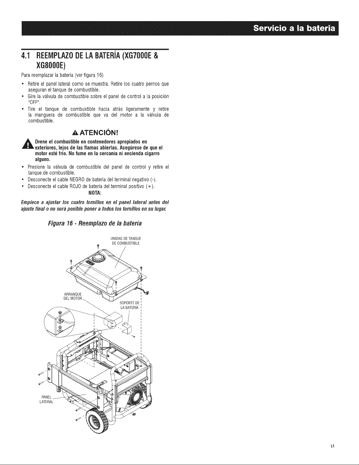
4.1 REEIVIPLAZ0DE LABATERJA(XG7000E&
XGB000E)
Para reempiazarla bateria (verfigura 16)
• Retire el panel lateral como se muestra. Retirelos cuatro pemos que
aseguraneltanque de combustible.
• Gire la va.lvulade combustible sobre el panel de control a la posicbn
"OFF".
• Tire el tanque de combustible hacia atra.s ligeramente y retire
la manguera de combustible que va del motor a la va.lvula de
combustible.
,A ATENCI(SN!
,_ Drene el combustibleen contenedoresapropiados en
exteriores, lejosde lasfiamas abiertas. Asegurese de que el
motor este frio. No fume en la cercania ni encienda cigarro
alguno.
• Presione la valvula de combustible del panel de control y retire el
tanquede combustible.
• Desconecteel cable NEGROde bateria del terminal negativo (-).
• Desconecteel cable ROJOde bateria del terminal positivo (+).
NOTA:
Empiece a ajustar los cuatro tomillos en el panel lateral antes del
ajuste final o no sera posible porter a todos los tomillos en su Ingar.
Figura 15 - Reemplazo de la bateria
UNIDADDETANQUE
DECOMBUSTIBLE
ARRANQUE
DELM(
SOPORTEDE
LA BATERiA
PANEL
LATERAL
15
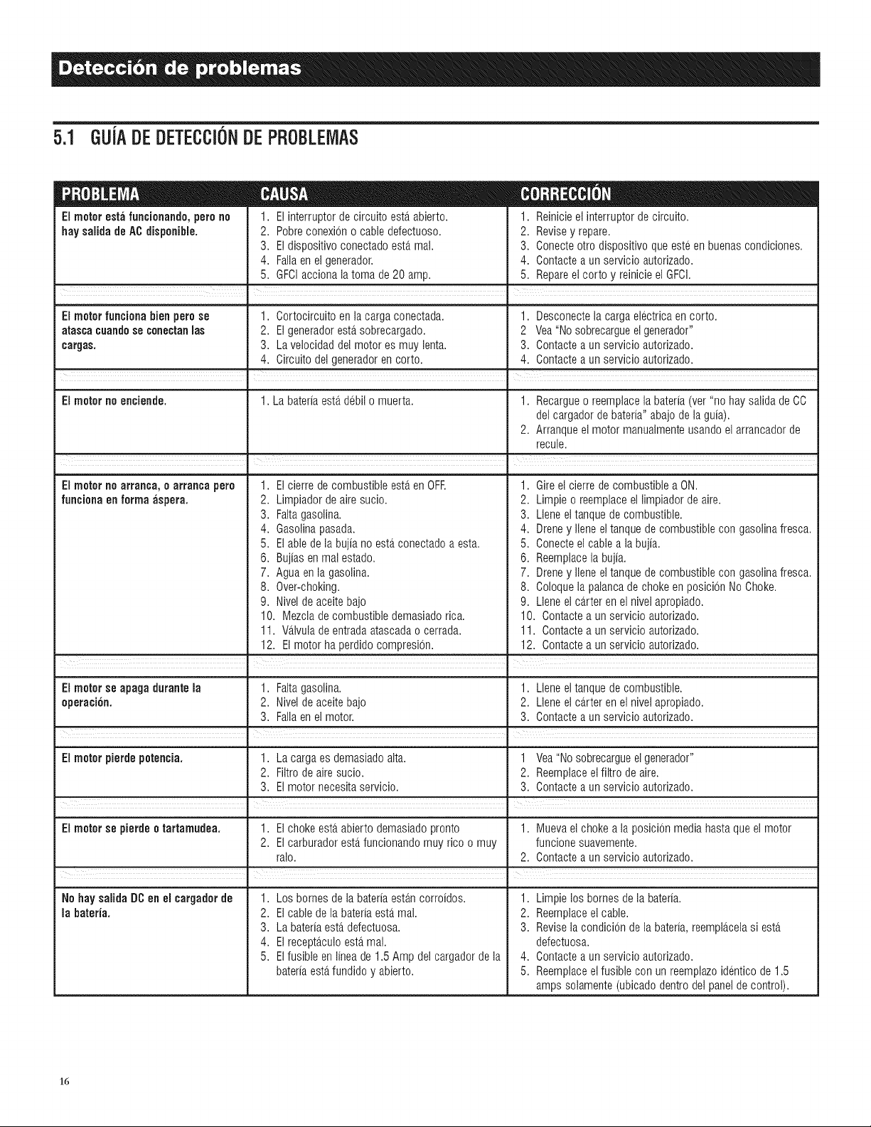
5.1 GUJADEDETECCI6NDEPROBLEMAS
El motorestafuncionando,perono
haysaiida deACdisponibie.
1. Elinterrupterdecircuitoesta.abierto.
2. Pobreconexiono cabledefectuoso.
3. Eldispositivoconectadoesta.mai.
4. Fallaenelgenerador.
5. GFCIaccionalatoma de 20 amp.
1. Reinicieel interrupterde circuito.
2. Revisey repare.
3. Conecteotro dispositivoque esteenbuenascondiciones.
4. Contactea un servicio autorizado.
5. Repareelcorto y reinicieel GFCI.
• =
El motor funcienabien perose 1. Cortocircuitoen la cargaconectada. 1. Desconectela cargaelectricaen corto.
atascacuandese canectanmas 2. Elgeneradoresta.sobrecargado. 2 Vea"Nosobrecargueelgenerador"
cargas. 3. La velocidaddel motores muy lenta. 3. Contactea un servicioautorizado.
4. Circuitodel generadoren corto. 4. Contactea un servicioautorizado.
El meter no enciende. 1. La bateriaesta.debil o muerta. 1. Recargueo reemplacelabateria(ver"no hay saiidade CO
delcargadorde bateria"abajode laguia).
2. Arranqueel motor manuaimenteusandoel arrancadorde
recule.
I
1. Elcierre de combustibleesterenOFR
2. Limpiadorde airesucio.
3. Faltagasolina.
4. Gasolinapasada.
5. Elable de la bujiano esterconectadoa esta.
6. Bujiasen realestado.
7. Aguaen la gasolina.
8. Over-choking.
9. Nivelde aceitebajo
10. Mezcladecombustibledemasiadorica.
11. V_tlvulade entradaatascadao cerrada.
12. El motor ha perdidocompresi6n.
EJmotetno arranca, e arranca pare
funciaflaen farinaaspera.
1. Gireel cierrede combustiblea ON.
2. Limpieo reemplaceellimpiadorde aire.
3. Lleneeltanquede combustible.
4. Dreney Ileneeltanquede combustiblecon gasolinafresca.
5. Conecteel cablea labujia.
6. Reemplacela bujia.
7. Dreney Ileneeltanquede combustiblecon gasolinafresca.
8. Coloquela palancade chokeen posicionNoChoke.
9. Lleneel ca.rteren el nivelapropiado.
10. Contactea un servicio autodzado.
11. Contactea un servicio autodzado.
12. Contactea un servicio autorizado.
!
• |
El motorse apagadurante la 1. Faltagasolina. 1. Lleneeltanquede combustible.
eperaci6n. 2. Nivelde aceitebajo 2. Lleneel ca.rteren el nivelapropiado.
3. Failaenelmotor. 3. Contactea un servicioautorizado.
I I
El meterpierdepetencia. 1. La cargaes demasiadoaita. 1 Vea"Nosobrecargueel generador"
2. Filtrode airesucio. 2. Reemplaceelfiltro deaire.
3. Elmotornecesitaservicio. 3. Contactea un servicioautorizado.
m
El motor se pierdee tartamudea. 1. Elchokeesterabiertodemasiadopronto 1. Muevael chokea la posicionmediahastaqueel motor
2. Elcarburadoresterfuncionandomuy rico o muy funcionesuavemente.
ralo. 2. Contactea un servicioautorizado.
, .
No haysaiida DCen el cargaderde
la bateria.
1. Los bornesde la bateriaesta.ncorroidos.
2. Elcable de la bateriaesta.mai.
3. La bateriaesta.defectuosa.
4. Elrecepta.culoesta.mai.
5. Elfusible en lineade 1.5 Ampdel cargadorde la
bateriaesta.fundidoy abierto.
1. Limpielosbornesde la bateria.
2. Reemplaceelcable.
3. Revisela condicionde la bateria,reempla.celasiesta.
defectuosa.
4. Contactea un servicioautorizado.
5. Reemplaceelfusible con un reemplazoidenticode 1.5
ampssolamente(ubicadodentrodel panelde control).
16

17
DECLARACl6N DE GARANT{A DE CONTROL DE EMISIONES FEDERAL Y DE CALiFORNiA
SUS DERECHOS Y OBMGACIONES DE GARANTiA
El directorio de recursos de aire de California (CARB) y la Agencia de protecci6n ambiental de los Estados Unidos (EPA) junto con
Generac Power Systems, Inc. (Generac) se complacen en expticar la garantia del sistema de control de emisiones para su nuevo
generador det argo 2008 o posterior, equipo nuevo que use motores pequehos de chispa deben estar disehados, construidos
y equipados para cumplir est&ndares anti-smog muy exigentes para et gobierno federal y del Estado de California. Generac
garantizar& los sistemas de emisi6n en su motor por el periodo de tiempo listado abajo siempre que no haya abuso, negligencia,
modificaci6n o mantenimiento inapropiado de su equipo.
Su sistema de control de emisi6n puede inctuir partes como: carburador, sistema de ignici6n, convertidor catalitico, tanque
de combustible, tapa de combustible, v&Ivutas, lata de carb6n, fittros, mangueras de vapor, abrazaderas, conectores, y otros
componentes relacionados a la emisi6n (si existieran).
COBERTURA DE LA GARANT{A DEL FABRICANTE:
Este sistema de control de emisi6n est& garantizado pot dos argos. Si durante este periodo de garantia se encuentra que cuatquier
parte retacionada alas emisiones est& defectuosa en materiales o mano de obra, se efectuar& las reparaciones o el intercambio
por parte de un concesionario de servicio autorizado de Generac.
RESPONSABILIDADES DE GARANTiA DEL PROPIETARIO:
Como propietario del generador, usted es responsable de completar todos los mantenimientos requeridos tal como se lista en et
manual del propietario proporcionado pot la f&brica. Para prop6sitos de garantia, Generac recomienda que usted conserve todos
los recibos que cubren el mantenimiento de su generador, pero Generac no puede rehusar la garantia s61o debido a la fatta de
recibos.
Como propietario det generador, usted deber& ser consciente de que Generac puede negar cuatquier y/o todas las coberturas y
responsabilidades de la garantia si su generador, o una parte o componente del mismo, ha faltado debido al abuso, negligencia,
mantenimiento inapropiado o modificaciones no aprobadas, o el uso de repuestos fatsos o det mercado negro no fabricados,
suministrados o aprobados por Generac.
Usted es responsable de contactar a un concesionario autorizado de garantia de Generac tan pronto se presente el
problema. Las reparaciones de garantia deber_n cornpletarse en un tiempo razonable, sin e×ceder los 30 alias,
El servicio de garantfa puede arreglarse contactando ya sea a su concesionario de venta o a un concesionario de servicio de
garantfa autorizado de Generac. Para ubicar at concesionario de servicio de garanfia autorizado de Generac m&s cercano a usted,
Ilame a nuestro n0mero gratuito.
1=800=333=1322
NOTA IMPORTANTE: Esta dectaraci6n de garantfa explica sus derechos y obligaciones bajo la Garantia det sistema de
control de emisiones (ECS Warranty), que Generac le proporciona Generac siguiendo las leyes federates y de California.
Tambi6n vea "Garantias limitadas de Generac para los sistemas de potencia de Generac, Inc." que se adjunta a este manual
en una hoja separada, tambi_n proporcionada a usted por Generac. Tenga en cuenta que esta garantia no se apticar& a
ning0n dar_o incidental, consecuenciat o indirecto causado por defectos en los materiales y mano de obra, o cuatquier retraso
en reparar o reemplazar las partes defectuosas. Esta garanfia reemplaza a todas las otras garantias, expresas o implicitas.
ESPECiFICAMENTE, GENERAC NO OFRECE OTRAS GARANTiAS COMO DE MERCANTIBILIDAD O ADECUACION A UN
USO PARTICULAR. Algunos estados no permiten limitaciones en cu&nto dura una garantia implicita, de modo que la limitaci6n
expresada arriba puede no aplicarse a usted.
La garantia ECS se aptica s61o at sistema de control de emisiones de su nuevo equipo. Si hay algOn conflicto en t6rminos
entre ta garantia ECS y la garantia de Generac, se aplicar& la de Generac. Ambas garantias describen derechos y obligaciones
importantes respecto a su nuevo motor.
El servicio de garantia puede ser realizado s61o por un servicio de garantia autorizado de Generac. Cuando se requiera servicio de
garantia, se debe presentar evidencia que muestre la fecha de venta at comprador/propietario original.
Si usted tuviera atguna pregunta respecto a sus derechos y responsabilidades de garantia, deber& ponerse en contacto con
Generac en la siguiente direcci6n:
ATENCION DEPARTAMENTO DE GARANT{AS
GENERAC POWER SYSTEMS, INC.
RO. BOX 297 ', WHITEWATER, WI 53190
Parte 1
Part No. 0H1913 Rev.A 01/09
18
GARANTiA DEL SISTEMA DE CONTROL DE EMISIONES
Garantia de sistema de control de emisiones (garantia ECS) para equipo que usa motores pequehos de chispa.
(a) Aplicabilidad: Esta garantia se aplica a equipo que utiliza motores pequehos para fuera de pista. Et periodo de garantia
ECS empezar& en la fecha en que el equipo nuevo es comprado por o entregado a su propietario/comprador final original y
continuar& por los siguientes 24 meses consecutivos.
(b) Cobertura general de la garantia de emisiones: Generac garantiza al propietario/comprador final original del motor o
equipamiento nuevo y a cada subsiguiente comprador/propietario que el ECS cuando se instal6 estuvo:
(1) Disehado, construido y equipado para cumplir con todas las regutaciones aplicables: y
(2) Libre de defectos en materiates y mano de obra que cause la fatla de una parte garantizada en cuatquier momento
durante et periodo de garantfa ECS.
(c) La garantia sobre partes relacionadas a ta emisi6n se interpretar&n como sigue:
(1) Cuatquier parte garantizada que no est6 programada para reemplazo como mantenimiento requerido en el Manual det
propietario ser& garantizada en el periodo de garantia ECS. Si faltara cualquier parte durante el periodo de garantia
ECS, deber& ser reparado o reeemptazado por Generac de acuerdo a la Subsecci6n (4) m&s abajo. Cuatquier parte asi
reparada o reemplazada bajo la garantia ECS deber& ser garantizada por el resto det periodo de garantia ECS.
(2) Cuatquier parte garantizada que est_ programada s6to para inspecci6n regular como se especifica en el Manual del
propietario ser& garantizada en et periodo de garantia ECS. Una declaraci6n en el manual det propietario a efecto de
"reparar o reemplazar seg0n sea necesario" no reducir& el periodo de garantia ECS. Cuatquier parte asi reparada o
reemplazada bajo la garantia ECS deber& ser garantizada por el resto del periodo de garantia ECS.
(3) Cuatquier parte garantizada que est_ programada para reemptazo seg0n Io requiera el mantenimiento en el Manual del
Propietario deber& ser garantizado por el periodo de tiempo antes del primer punto de reemplazo programado para esa
parte. Si ta parte falla antes del primer reemptzao programado, la parte ser& reparada o reemplazada por Generac de
acuerdo a la Subsecci6n (4) m&s abajo. Cuatquier parte relacionada atas emisiones asi reparada o reemplazada bajo la
garantia ECS ser& garantizada por el resto det periodo antes det primer punto de reemplazo programado para aquetla
parte.
(4) La reparaci6n o reemptazo de cualquier parte garantizada relacionada alas emisiones bajo esta garantia ECS deber&
reatizarse sin costo alguno para el propietario en un centro de servicio de garantia autorizado por Generac.
(5) No obstante las disposiciones de la subseccion (4) arriba indicadas, los servicios o reparaciones por garantia deben ser
proporcionados en una instataci6n de servicio autorizada por Generac.
(6) Cuando el motor sea inspeccionado por un centro de servicio de garantia autorizado de Generac, el propietario/comprador
no ser& responsabte de los costos de diagn6stico si ta reparaci6n se considera dentro de la garantia.
(7) A Io largo det periodo de garantia ECS, Generac mantendr& un suministro de partes garantizadas relacionadas a las
emisiones suficiente para cumptir la demanda esperada para tales repuestos.
(8) Cualquier repuesto relacionado a la emisi6n autorizado y aprobado por Generac puede usarse en la ejecuci6n de cualquir
reparaci6n o mantenimiento de garantia ECS y se proporcionar& sin costo at comprador/propietario. Dicho uso no reducir&
las obligaciones de garantia ECS de Generac.
(9) Los repuestos no aprobados, ar_adidos, modificados, falsos y/o del mercado negro no se pueden usar para modificar
o reparar un motor Generac. Dicho uso invatida esta garantia ECS y ser& base suficiente para no aceptar un rectamo
por garantia ECS. Generac no podr_, ser dectarado responsabte por fattas de cualquier parte garantizada de un equipo
Generac causadas por el uso de tales repuestos no aprobados, ar_adidos, modificados, fatsos y/o det mercado negro.
LAS PARTES RELAClONADAS A LA EMISl0N PUEDEN INCLUIR LO SlGUIENTE
(Sl SE TIENE):
1) SISTEMA DE COMBUSTIBLE 3) SISTEMA DE MEDtCION DE COMBUSTIBLE
A. TANQUE DE COMBUSTIBLE A. CARBURADOR Y PARTES INTERNAS
B. TAPA DE COMBUSTIBLE B. REGULADOR DE PRESTON
C. L[NEA DE COMBUSTIBLE 4) SISTEMA DE INDUCCION DE AIRE
D. ACCESORIOS DE LA L[NEA DE COMBUSTIBLE A. DtSTRIBUIDOR DE ENTRADA
E. ABRAZADERAS* B. FILTRO DE AIRE
R VALVULAS DE LIBERACION DE PRESlON* 5) SISTEMA DE IGNtCION
2) SISTEMA DE CONTROL EVAPORADOR A. BUJ[AS
A. LATA DE CARBON B. BOBtNAS/MODULO DE IGNICtON
B. SOPORTES DE MONTAJE DE LA LATA 6) SISTEMA DE INYECCION DE AtRE
C. PUERTO DE PURGA DEL CARBURADOR A. VALVULA DE AIRE DE PULSO
D. VALVULAS DE CONTROL* 7) SISTEMA DE ESCAPE
E. MANGUERAS DE VAPOR A. CATALIZADOR
R VALVULAS DE PURGA B. REACTOR TERMtCO
G. SEPARADOR L[QUIDO / VAPOR C. DtSTRIBUIDOR DE ESCAPE
H. DtAFRAGMAS DE CONTROL DE VAC[O*
*NOTA: Como se relacionen con el sistema de control de emisiones.
Parte 2
Part No. 0H1913 Rev.A 01/09
19
GARANTiA UMITADA DE "DOS ANOS" DE S|STEMAS DE POTENC|A GENERAC PARA
GENERADORES PORTAT|LES SERIE XG
Por un periodo de dos ahos desde la fecha de la venta original, Generac Power Systems, Inc. (Generac) garantiza sus generadores serieXG como libres de defectos en
materiales y mano de obra por los items y periodos indicados abajo. Generac, a su opcion, reparara o reemplazara cualquier parte que, luego de un examen, inspeccion
y pruebas realizadas por un concesionario de servicio de garantia autorizado de Generac, se encuentre que esta defectuoso. Cualquier equipo que el comprador/
propietario reclame como defectuoso debe ser regresado a y examinado por el concesionario de servicio de garantia autorizado por Generac mas cercano. Todos los
costos de transporte bajo la garantia, incluyendo el retorno a la fabrica, seran por cuenta y prepagados por el propietario/comprador. Esta garantia se aplica solo a los
generadores portatiles serie XG de Generac y no es transferible del propietario original. Guarde su comprobante de compra. Si usted no proporciona una prueba de la
fecha de la compra inicial, se usara la fecha de embarque del producto del fabricante para determinar el periodo de garantia.
PROGRAMACION DE GARANTiA
Las aplicaciones para consumidor estan garantizadas por dos (2) ahos. Las aplicaciones comerciales y de alquiler estan garantizadas por uno (1) ahos o 1000 horas
como maximo, Io que Ilegue primero.
APUOAOIONPARAOONSUIVlIDOR
ANOS UNO- 100% (cien por ciento) de cobertura en mano de obra y repuestos (se requiere comprobante de compra y mantenimiento):
, Todos los componentes
AI_ODOS - 100% (cien por ciento) de cobertura en repuestos (se requiere comprobante de compra y mantenimiento):
,Todos los componentes
APUCACION COMERCIAL/ DIEALJUILER
ANOS UNO- 100% (cien por ciento) de cobertura en mano de obra y repuestos (se requiere comprobante de compra y mantenimiento):
, Todos los componentes
NOTA:Para el proposito de esta garantia "uso de consumidor" significa uso personal en casa residencial o recreacional por el comprador original. La garantia no aplica
a unidades usadas para FuentePrimaria de Energia en lugar del servicio publico donde el servicio publico se encuentre presente o donde el servicio publico de
energia no exista normalmente. Una vez que el generador ha experimentado uso comercial o de alquiler, se le considerara en adelante un generador no para uso
del consumidor para propositos de esta garantia.
Toda prestacion de gastos de garantia esta sujeta alas condiciones definidas en las politicas de garantia de Generac, sus procedimientos y el manual de costos medios.
ESTAGARANTiANOSEAPUCABAA LOSIGUIENTE:
Generadoresportatiles de Generacque utilizan repuestos que no son de Generac.
Costos de mantenimiento normal y ajustes.
Fallascausadas por combustibles o aceites contaminados, o la falta de niveles apropiados.
Reparacioneso diagnosticos realizadospor individuos diferentesa los concesionarios autorizados por Guardian/Generacque no esten autorizadospor escrito por Generac
Power Systems.
Fallasdebido a, pero no limitandose a, el usey desgaste normal, accidente, mal use, abuse, negligenciao use inapropiado.Come todo dispositivo mec&nico,los motores
Generacnecesitan servicio y repuestos periodicamente parafuncionar come estan disehados. Esta garantiano cubre reparacionescuando el use normal ha agotado la vida
util de una parte o motor.
Lasfallas causadas por cualquieracto de Dios y otros eventos de fuerza mayor mas all& del control delfabricante.
Eldaho relacionadoa roedores y/o plaga de insectos.
Los productos que son modificados o alterados de manera no autorizada por Generacpor escrito.
Cualquierda_o incidental, consecuencial o indirecto causadopor defectos en materiales y mano de obra, o cualquier retraso en reparar o reemplazar las partes defectuosas.
Falladebido a unamala aplicacion.
Gastosde telefono, telefono celular,fax, acceso a internet u otros gastos de comunicacion.
Costo de vida o gastos deviaje de las personas que realizanel servicio, excepto tal come especificamente se incluya dentro de los terminos del periodode garantiade una
unidad especifica.
Gastosrelacionados a "instrucciones del cliente" o deteccion de problemasdonde no se encuentredefecto de f&brica.
Equipo de alquiler usado mientras se realizalas reparacionesde garantia.
Fletede un dia para otro o costos especiales de embarque para los repuestos.
Sobretiempos, vacaciones o trabajo de emergencia.
Bateriasde arranque, fusibles, filtros, bombillos de luz y fluidos de motoK
STA GARANTiAREEMPLAZACUALQUIEROTRA GARANTiA,EXPRESA0 IMPLiCITA, ESPECiFICAMENTE,GENERACPOWERSYSTEMSNO OTORGAOTRASGARANTiAS
COMODE MERCANTIBILIDAD0 ADECUACIONPARA UN PROPOSITOPARTICULAR.Cualquier garantia implicita que sea permitida por ley, estara limitada en duracion a
los terminos de la garantia expresa dispuesta aquL AIgunos estados no permiten limitaciones en cuanto dura una garantia implicita, de modo que la limitacion expresada
arriba puede no aplicarse al comprador/propietario.
LA ONICARESPONSABILIDADDEGENERACPOWERSYSTEMSSERA,LA REPARACION0 REEMPLAZODELASPARTESTALCOMOSEESPECIFICAARRIBA.EN
NINGUNCASOGENERACPOWERSYSTEMSSERA,RESPONSABLEPORCUALQUIERDAI_OINCIDENTAL0 CONSECUENCIAL,AONSITALESDAI_OSSEANUN
RESULTADODIRECTODEUNANEGLIGENCIADEGENERACPOWERSYSTEMS.Algunosestadosno permitenla exclusiono limitaciondedahosincidentaleso
consecuenciales,asi quelas limitacionesindicadasarribapuedenno aplicarsealcomprador/propietario.Elcomprador/propietarioestade acuerdoen no hacerreclamos
contraGeneracPowerSystemsbasadosennegligencia.Estagarantiale da alcomprador/propietarioderechoslegalesespecificos.Elcomprador/propietariotambien
_uedetenerotrosderechosquevariande estadoa estado.
GENERACPOWERSYSTEMS,INC.
P.O.BOX8 • Waukesha, Wl 53187
Tel: (888) GENERAC(436-3722) • Fax: (262) 544-4851
Para ubicaral concesionario autorizado re;is cercano visite nuestro sitioweb: www.generac.com
Parte No. 0H5472
Revision B (20/10/09) Impreso en los EE.UU.
Manual Part No. 0H3530 RevisionE (30/09/10) Impreso en los EE.UU.