
SWARS
owner's
manual
Model
C950-52935-1
CAUTION:
You must read and
understand this owner's
manual before operating
unit.
Serial No.
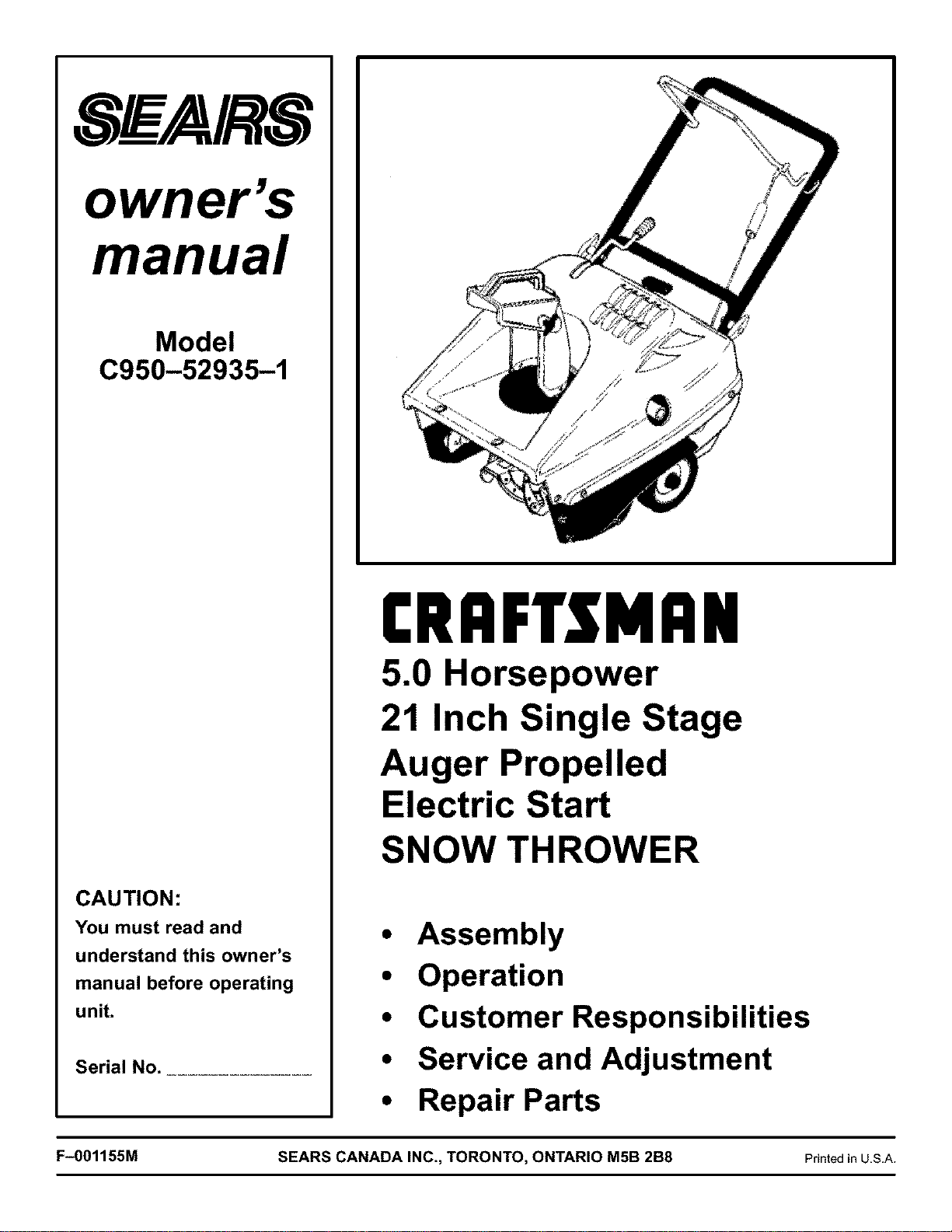
[RAFTSMRN
5.0 Horsepower
21 Inch Single Stage
Auger Propelled
Electric Start
SNOW THROWER
• Assembly
• Operation
• Customer Responsibilities
• Service and Adjustment
• Repair Parts
F-001155M SEARS CANADA INC., TORONTO, ONTARIO M5B 2B8 PrintedinU.S.A.
RULES FOR SAFE OPERATION
IMPORTANT
,_ WARNING: Always disconnect the spark plug wire and place it where it cannot make contact with
spark plug to prevent accidental starting during: Preparation, Maintenance, or Storage of your
4L
snow blower.
SAFE OPERATION PRACTICES FOR WALK-BEHIND SNOW BLOWER
DO NOT OPERATE THIS EQUIPMENT BEFORE READING THIS MANUAL
Engine Exhaust, some of its constituents, and
certain vehicle components contain or emit
chemicals known to the State of California to
cause cancer and birth defects or other repro-
ductive harm.
Battery posts, terminals and related accesso-
ries contain lead and lead compounds, chemi-
cals known to the State of California to cause
cancer and birth defects or other reproductive
harm. WASH HANDS AFTER HANDLING.
TRAINING
1. Read the operating and service instructionmanual care-
fully. Be thoroughly familiar with the controls and the
proper use of the equipment. Know how to stop the unit
and disengage the controls quickly.
2. Never allow children to operate the equipment. Never al-
low adults to operate the equipment without proper in-
struction.
3. Keep the area of operation clear of all persons, particu-
larly small children and pets.
4. Exercise caution to avoid slipping or falling especially
when operating in reverse.
PREPARATION
1. Thoroughly inspect the area where the equipment is to
be used and remove ait doormats, sleds, boards, wires,
and other foreign objects.
2. Disengage all clutches before starting the engine.
3. Do not operate the equipment without wearing adequate
winter outer garments. Wear footwear that will improve
footing on slippery surfaces.
4. Handle fuel with care; it is highly flammable.
(a) Use an approved fuel container.
(b) Never add fuel to a running engine or hot engine.
F-001155M
(c) Fill fuel tank outdoors with extreme care. Never fill
fuel tank indoors.
(d) Replace gasoline cap securely and wipe up spilled
fuel.
5. For all units with electric starting motors use electric
starting extension cords certified CSA/UL. Use only with
a receptacle that has been installed in accordance with
local inspection authorities.
6. Adjust the auger housing height to clear gravel or
crushed rock surface.
7. Under no circumstances should any adjustments be
made while the engine is running (except when specifi-
cally recommended by manufacturer).
8. Let engine and machine adjust to outdoor temperatures
before starting to clear snow.
9. Always wear safety glasses or eye shields during opera-
tion or while performing an adjustment or repair to protect
eyes from foreign objects that may be thrown from the
machine.
OPERATION
1. Do not put hands or feet near or under rotating parts.
Keep clear of the discharge opening at all times.
2. Exercise extreme caution when operating on or crossing
gravel drives, walks or roads. Stay alert for hidden haz-
ards or traffic.
3. Never discharge snow onto public roads or near moving
traffic.
4. After striking a foreign object, stop the engine, remove
the wire from the spark plug, thoroughly inspect snow
blower for any damage, and repair the damage before re-
starting and operating the snow blower.
5. If the unit should start to vibrate abnormally, stop the en-
gine and check immediately for the cause. Vibration is
generally a warning of trouble.
6. Stop the engine and remove spark plug wire whenever
you leave the operating position, before unclogging the
augedlmpeller housing or discharge chute and when
making any repairs, adjustments, or inspections.
7. When cleaning, repairing, or inspecting, make certain
the auger/Impeller and all moving parts have stopped
and all controls are disengaged. Disconnect the spark
plug wire and keep the wire away from the spark plug to
prevent accidental starting.

RULES FOR SAFE OPERATION
8. Take all possible precautions when leaving the snow
blower unattended. Disengage the auger/impeller, shift
to neutral, stop engine, and remove key.
9. Do not run the engine indoors, except when starting the
engine and for transporting the snow blower in or out of
the building. Ensure the outside doors are open; exhaust
fumes are dangerous.
10. Do not clear snow across the face of slopes. Exercise ex-
treme caution when changing direction on slopes. Do not
attempt to clear steep slopes.
11. Never operate the snow blower without proper guards,
plates or other safety protective devices in place.
12. Never operate the snow blower near enclosures, auto-
mobiles, window wells, drop-offs, and the like without
proper adjustment of the snow discharge angle. Keep
children and pets away.
13. Do not overload the machine capacity by attempting to
clear snow at too fast a rate.
14. Never operate the machine at high transport speeds on
slippery surfaces. Look behind and use care when back-
ing up.
15. Never direct discharge at bystanders or allow anyone in
front of the unit.
16. Disengage power to the collector/impeller when snow
blower is transported or not in use.
17. Use only attachments and accessories approved by the
manufacturer of the snow blower (such as wheel
weights, counterweights, cabs, and the like).
18. Never operate the snow blower without good visibility or
light. Always be sure of your footing and keep a firm hold
on the handles.
MAINTENANCE AND STORAGE
1. Check shear bolts and other bolts at frequent intervals for
proper tightness to be sure the equipment is insafe work-
ing condition.
2. Never store the machine with fuel in the tank inside a
building where ignition sources are present such as hot
water and space heaters, clothes dryers, and the like. Al-
low the engine to cool before storing in any enclosure.
3. Always refer to operator's guide instructions for impor-
tant details if the snow blower is to be stored for an ex-
tended period.
4. Maintain or replace safety and instruction labels, as nec-
essary.
5. Run the machine 2 minutes with auger clutch lever en-
gaged after blowing snow to prevent freeze-up of the au-
ger/impeller.
WARNING: Do not
use hands to un-
clog discharge _%
chute.
• Stop engine/motor before removing debris.
• Do not walk in front of running machine.
• Do not discharge at bystanders.
• Keep people and pets a safe distance from the
machine.
• Before leaving machine, shut off engine/motor
and remove key.
19. Do not over-reach. Keep proper footing and balance at
all times.
20. Do not attempt to use snow blower on a roof.
WARNING: Avoid
injury from rotating
auger- keep hands,
feet, and clothing
away.
F-001155M 3
OWNER'S INFORMATION
DATE PURCHASED:
MODEL NO:
SERIAL NO:
STORE WHERE PURCHASED:
ADDRESS:
CITY: PROVINCE:
TELEPHONE :
_Record this information about your unit so that you will
be able to provide it in case of loss or theft.
MAINTENANCE AGREEMENT
The Craftsman Warranty, plus a Maintenance
Agreement, provide maximum value for Sears
products. Contact your nearest Sears store for de-
tails.
Horse Power 5 HP
Gasoline Capacity 1.62 quarts (1.53 litre)
Fuel/Oil Mix Ratio 40:1 (3.2 ounces of air-
cooled 2-cycle engine oil
specified for 40:1 ratio per 1
gallon gasoline)
Spark Plug Champion RJCSY
Gap 0.030 in.
CUSTOMER RESPONSIBILITIES
Read and observe the safety rules.
Follow a regular schedule in maintaining, caring for and
using your snow blower.
Follow the instructions under "Customer Responsibilities"
and "Storage" sections of this owner's manual.
WHEELED SNOW BLOWER
LIMITED TWO (2) YEAR WARRANTY ON CRAFTSMAN SNOW BLOWER
For two (2) years from date of purchase, Sears Canada Inc. willrepair or replace free of charge, at Sears option, parts
which are defective as a result of material or workmanship.
COMMERCIAL OR RENTAL USE:
Warranty on snow blower will be 90 days from date of purchase ifused for commercial or rental purposes.
THIS WARRANTY DOES NOT COVER:
1. Pre-detivery set-up.
2. Expendable items which become worn during normal use, such as belts, spark plugs, filter, shear pins as well as dam-
ages to the engine resulting from operating the snow blower with insufficient oil.
3. Tire replacement or repair caused by punctures from outside objects, such as nails, thorns, stumps or glass.
4. In home service.
Warranty service is available by returning the Craftsman snow blower to the nearest Sears Service Centre/Department
in Canada. This warranty applies only while this product is in use in Canada.
This warranty is in addition to any statutory warranty and does NOT exclude or limit legal rights you may have but shall
run concurrently with applicable provincial legislation. Furthermore, some provinces do not allow limitations on how long
an implied warranty wilt last so the above limitations may not apply to you.
SEARS CANADA INC., TORONTO, ONTARIO M5B 2B8
F-001155M 4
TABLE OF CONTENTS
RULES FOR SAFE OPERATION .................................. 2
OWNER'S INFORMATION ....................................... 4
ASSEMBLY .................................................... 6
PARTS BAGS CONTENTS: .................................... 6
TOOLS REQUIRED FOR ASSEMBLY ........................... 6
HOW TO REMOVE FROM THE CARTON ........................ 6
HOW TO ASSEMBLE THE HANDLE ............................ 6
N CHECKLIST ............................................... 6
OPERATION .................................................... 7
ENGINE AND SNOW THROWER OPERATING CONTROLS ....... 7
SNOW BLOWER OPERATION ................................. 8
HOW TO STOP THE SNOW THROWER ........................ 8
TO CONTROL SNOW DISCHARGE ............................. 8
HOW TO THROW SNOW ...................................... 8
HOW TO MOVE FORWARD .................................... 8
SERVICE RECOMMENDATIONS ................................. 12
CUSTOMER RESPONSIBILITIES ................................. 13
HOW TO REMOVE THE TOP COVER ........................... 13
HOW TO REMOVE THE BELT COVER .......................... 13
ADJUSTMENT/REPAIR .......................................... 14
HOW TO ADJUST THE CHUTE CRANK ......................... 14
HOW TO ADJUST THE AUGER CONTROL CABLE ............... 14
HOW TO SET THE DRIVE BELT TENSION ...................... 15
HOW TO SET REPLACE THE DRIVE BELT ...................... 15
HOW TO REPLACE THE AUGER ............................... 16
HOW TO ADJUST THE CARBURETOR ......................... 17
HOW TO ADJUST OR REPLACE THE SPARK PLUG ............. 17
STORAGE ...................................................... 18
TROUBLE SHOOTING CHART ................................... 19
F-001155M 5
ASSEMBLY
PARTS BAGS CONTENTS:
1 - 3.2 ounces Craftsman 2-cycle oil
1 - Owner's Manual
1 - Starter Cord
TOOLS REQUIRED FOR ASSEMBLY
1-Knife
_b WARNING: Always wear safety glasses or eye
shields while assembling snowblower.
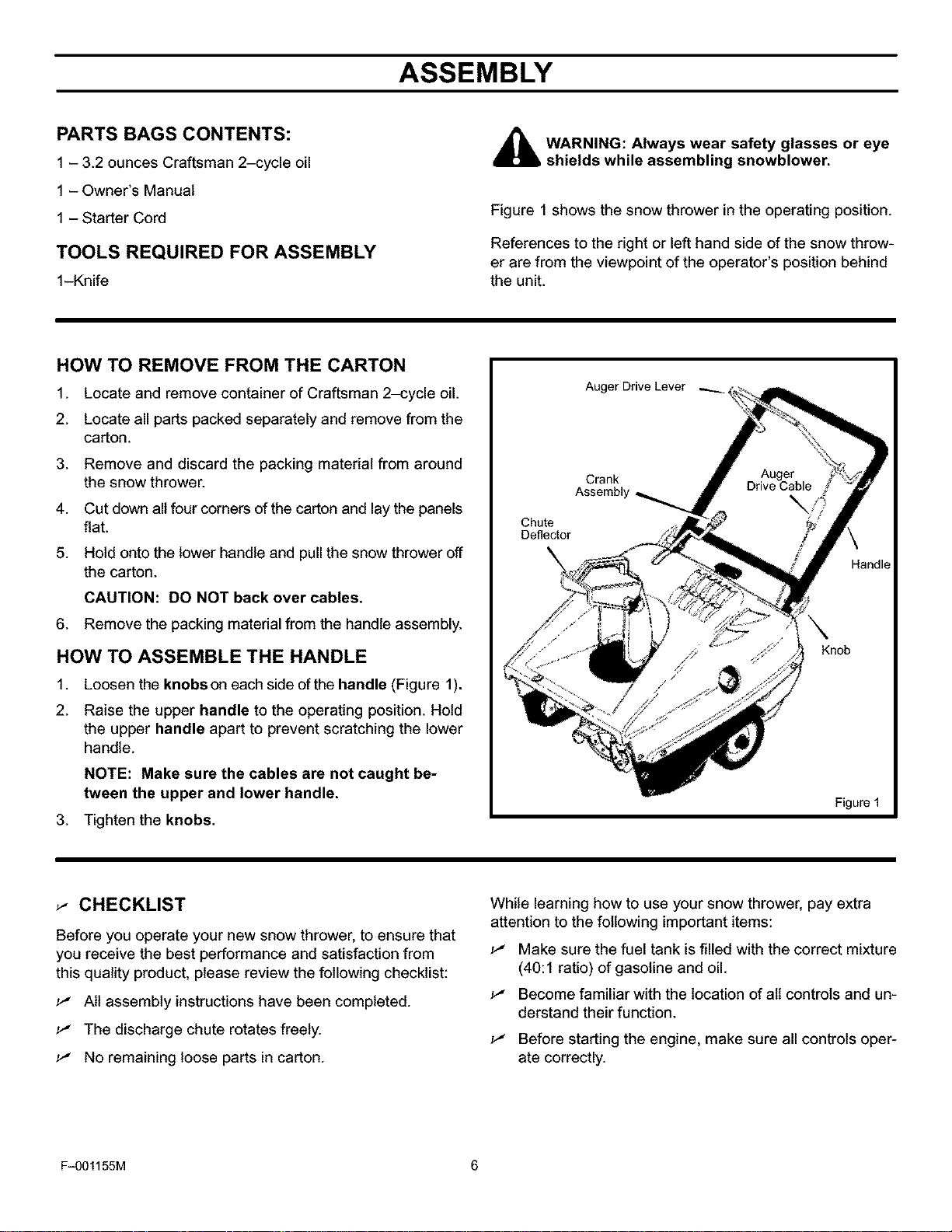
Figure 1 shows the snow thrower in the operating position.
References to the right or left hand side of the snow throw-
er are from the viewpoint of the operator's position behind
the unit.
HOW TO REMOVE FROM THE CARTON
1. Locate and remove container of Craftsman 2-cycle oil.
2. Locate all parts packed separately and remove from the
carton.
3. Remove and discard the packing material from around
the snow thrower.
4. Cut down all four corners of the carton and lay the panels
flat.
5. Hold onto the lower handle and pull the snow thrower off
the carton.
CAUTION: DO NOT back over cables.
6. Remove the packing material from the handle assembly.
HOW TO ASSEMBLE THE HANDLE
1. Loosen the knobs on each side of the handle (Figure 1).
2. Raise the upper handle to the operating position. Hold
the upper handle apart to prevent scratching the lower
handle.
NOTE: Make sure the cables are not caught be-
tween the upper and lower handle.
3. Tighten the knobs.
_- CHECKLIST
Before you operate your new snow thrower, to ensure that
you receive the best performance and satisfaction from
this quality product, please review the following checklist:
._" Atl assembly instructions have been completed.
._" The discharge chute rotates freely.
._" No remaining loose parts in carton.
While learning how to use your snow thrower, pay extra
attention to the following important items:
._" Make sure the fuel tank is filled with the correct mixture
(40:1 ratio) of gasoline and oil.
._" Become familiar with the location of all controls and un-
derstand their function.
._" Before starting the engine, make sure all controls oper-
ate correctly.
F-001155M 6
OPERATION
KNOW YOUR SNOW THROWER
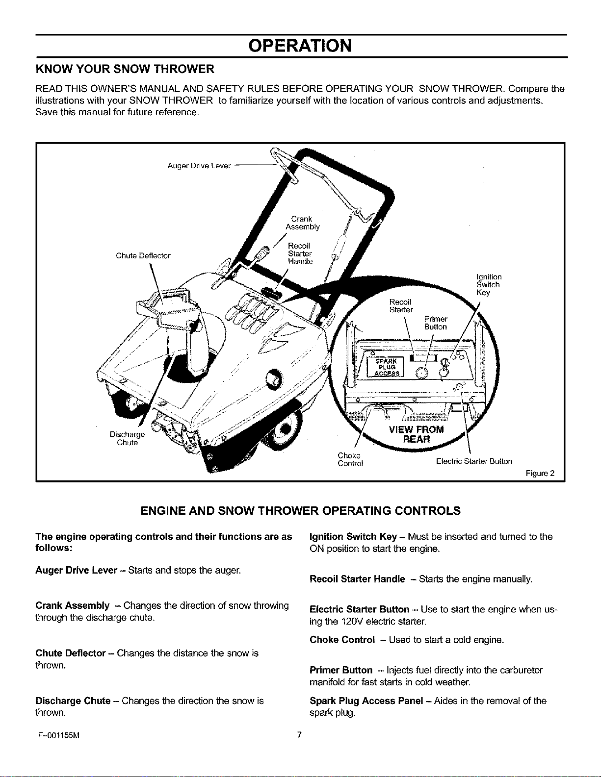
READ THIS OWNER'S MANUAL AND SAFETY RULES BEFORE OPERATING YOUR SNOW THROWER. Compare the
illustrationswith your SNOW THROWER to familiarize yourself with the location of various controls and adjustments.
Save this manual for future reference.
Auger Drive Lever
Chute Deflector
Ignition
Switch
Key
Discharge
Chute
Choke
Control Electric Starter Button
Figure 2
ENGINE AND SNOW THROWER OPERATING CONTROLS
The engine operating controls and their functions are as
follows:
Auger Drive Lever - Starts and stops the auger.
Ignition Switch Key - Must be insertedand turned to the
ON position to start the engine.
Recoil Starter Handle - Starts the engine manually.
Crank Assembly - Changes the direction of snow throwing
through the discharge chute.
Chute Deflector - Changes the distance the snow is
thrown.
Discharge Chute - Changes the direction the snow is
thrown.
Electric Starter Button - Use to start the engine when us-
ing the 120V electric starter.
Choke Control - Used to start a cold engine.
Primer Button - Injects fuel directly intothe carburetor
manifold for fast starts in cold weather.
Spark Plug Access Panel - Aides in the removal of the
spark plug.
F-001155M 7
OPERATION
_ The operation of any snow blower can result in foreign objects being thrown into the eyes,which canresult in severe eye damage. Always wear safety glasses or eye shields before beginning snow blower
Operation. We recommend standard safety glasses or Wide Vision Safety Mask for over spectacles.
SNOW BLOWER OPERATION
The most effective use of the snow blower will be established
by experience, taking into consideration the terrain, wind
conditions and building location which will determine the
direction of the discharge chute.
NOTE: Do not discharge snow toward a building as
hidden objects could be thrown with sufficient force to
cause damage.
,_ WARNING: Read Owner's Manual before oper-
ating machine. This machine can be dangerous
if used carelessly.
Never operate the snow blower without all guards, cov-
ers, and shields in place.
Never direct discharge toward windows or allow by-
standers near machine while engine is running.
Stop the engine whenever leaving the operating posi-
tion.
Disconnect spark plug before unclogging the impeller
housing or the discharge chute and before making re-
pairs or adjustments.
When leaving the machine, remove the ignition key.
To reduce the risk of fire, keep the machine clean and
free from spilled gas, oil and debris.
HOW TO STOP THE SNOW THROWER
1. To stop throwing snow, release the auger drive lever.
(See Figure 4).
2.
NOTE: If the snow thrower continues to slowly move
forward, see "How To Adjust The Auger Control
Cable" in the Service And Adjustment Section.
To stop the engine, move the ignition key to the OFF
position.
TO CONTROL SNOW DISCHARGE
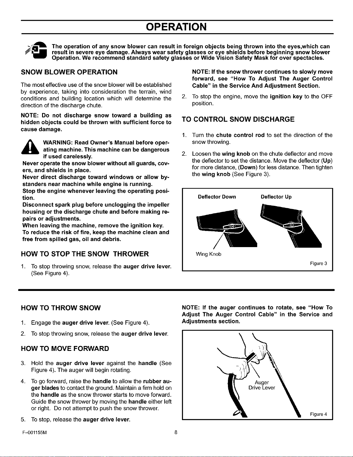
1.
2.
Turn the chute control rod to set the direction of the
snow throwing.
Loosen the wing knob on the chute deflector and move
the deflector to set the distance. Move the deflector (Up)
for more distance, (Down) for less distance. Then tighten
the wing knob (See Figure 3).
Deflector Down
Deflector Up
Wing Knob
Figure 3
HOW TO THROW SNOW
1. Engage the auger drive lever. (See Figure 4).
2. To stop throwing snow, release the auger drive lever.
HOW TO MOVE FORWARD
3. Hold the auger drive lever against the handle (See
Figure 4). The auger will begin rotating.
4. To go forward, raise the handle to allow the rubber au-
ger blades to contact the ground. Maintain a firm hold on
the handle as the snow thrower starts to move forward.
Guide the snow thrower by moving the handle either left
or right. Do not attempt to push the snow thrower.
5. To stop, release the auger drive lever.
NOTE: If the auger continues to rotate, see "How To
Adjust The Auger Control Cable" in the Service and
Adjustments section.
Auger
Figure 4
F-001155M 8
OPERATION
Mix gasoline and oilas follows:BEFORE STARTING THE ENGINE
d_lb WARNING: Experiences indicates that alcohol
blended fuels (called gasohol or those using
ethanol or methanol) can attract moisture
which leads to separation and formation of acids dur-
ing storage. Acidic gas can damage the fuel system
of an engine while in storage.
NOTE: To avoid engine problems, the fuel system
must be emptied before storage for 30 days or longer.
Start the engine and let it run until the fuel lines and
carburetor are empty. Use the carburetor bowl drain
to empty residual gasoline from the float chamber.
Use fresh fuel next season. See the Storage section in
this manual for additional information.
Never use engine or carburetor cleaner products in the
fuel tank or permanent damage can occur.
HOW TO MIX THE FUEL MIXTURE
The two cycle engine, used on this snow thrower, requires
a mixture of gasoline and oil for lubrication of the bearings
and other moving parts. The correct fuel mixture ratio is
40:1 (3.2 oz. oil per one gallon of gas - see the Fuel Mix-
ture Chart). Gasoline and oil must be pre-mixed in a clean
gasoline container. Always use fresh, clean, unleaded gas-
oline.
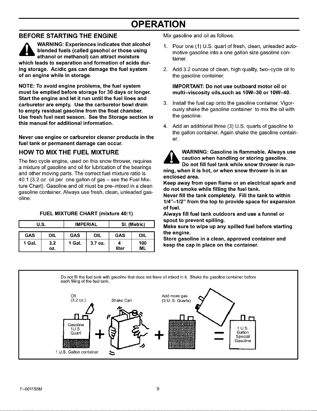
FUEL MIXTURE CHART (mixture 40:1)
U.S. I IMPERIAL I SL (Metric)
GAS OIL GAS OIL | GAS OIL
1 GaL 3.2 1 GaL 3.7 oz. T 4 100
oz. liter ML
1. Pour one (1) U.S. quart of fresh, clean, unleaded auto-
motive gasoline into a one gallon size gasoline con-
tainer.
2.
.
4.
Add 3.2 ounces of clean, high quality, two-cycle oil to
the gasoline container.
IMPORTANT: Do not use outboard motor oil or
multi-viscosity oils,such as 10W-30 or 10W-40.
install the fuel cap onto the gasoline container. Vigor-
ously shake the gasoline container to mix the oil with
the gasoline.
Add an additional three (3) U.S. quarts of gasoline to
the gallon container. Again shake the gasoline contain-
er.
,_ WARNING: Gasoline is flammable. Always use
caution when handling or storing gasoline.
Do not fill fuel tank while snow thrower is run-
ning, when it is hot, or when snow thrower is in an
enclosed area.
Keep away from open flame or an electrical spark and
do not smoke while filling the fuel tank.
Never fill the tank completely. Fill the tank to within
1/4"-1/2" from the top to provide space for expansion
of fuel.
Always fill fuel tank outdoors and use a funnel or
spout to prevent spilling.
Make sure to wipe up any spilled fuel before starting
the engine.
Store gasoline in a clean, approved container and
keep the cap in place on the container.
Do not fill the fuel tank with gasoline that does not have oil mixed in it. Shake the gasoline container before
each filling of the fuel tank.
Oil Add more gas
(3.2 oz.) Shake Can (3 U. S. Quarts)
F-001155M 9
OPERATION
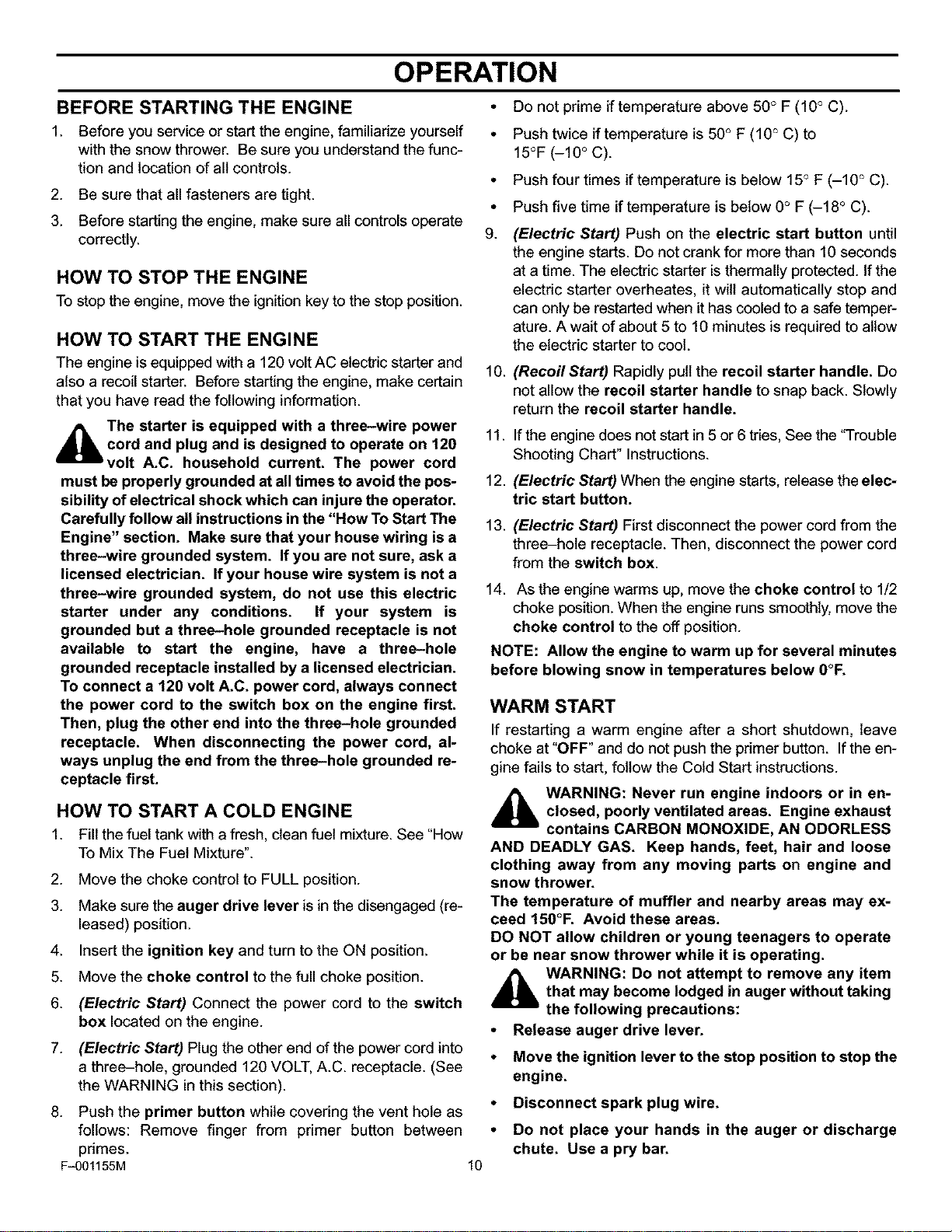
BEFORE STARTING THE ENGINE •
1. Before you service or start the engine, familiarize yourself •
with the snow thrower. Be sure you understand the func-
tion and location of all controls.
2. Be sure that all fasteners are tight.
3. Before starting the engine, make sure all controls operate
correctly. 9.
HOW TO STOP THE ENGINE
To stop the engine, move the ignition key to the stop position.
HOW TO START THE ENGINE
The engine is equipped with a 120 volt AC electric starter and
also a recoil starter. Before starting the engine, make certain
that you have read the following information.
_lb The starter is equipped with a three-wire power
cord and plug and is designed to operate on 120
volt A.C. household current. The power cord
must be properly grounded at all times to avoid the pos-
sibility of electrical shock which can injure the operator.
Carefully follow all instructions in the "How To Start The
Engine" section. Make sure that your house wiring is a
three-wire grounded system. If you are not sure, ask a
licensed electrician. If your house wire system is not a
three-wire grounded system, do not use this electric
starter under any conditions. If your system is
grounded but a three-hole grounded receptacle is not
available to start the engine, have a three-hole
grounded receptacle installed by a licensed electrician.
To connect a 120 volt A.C. power cord, always connect
the power cord to the switch box on the engine first.
Then, plug the other end into the three-hole grounded
receptacle. When disconnecting the power cord, al-
ways unplug the end from the three-hole grounded re-
ceptacle first.
HOW TO START A COLD ENGINE
1. Fill the fuel tank with a fresh, clean fuel mixture. See "How
To Mix The Fuel Mixture".
F-001155M
2. Move the choke control to FULL position.
3. Make sure the auger drive lever is in the disengaged (re-
leased) position.
4. Insert the ignition key and turn to the ON position.
5. Move the choke control to the full choke position.
6. (Electric Start) Connect the power cord to the switch
box located on the engine.
7. (Electric Start) Plug the other end of the power cord into
a three-hole, grounded 120 VOLT, A.C. receptacle. (See
the WARNING in this section).
8. Push the primer button while covering the vent hole as
follows: Remove finger from primer button between
primes.
10
10.
Do not prime if temperafure above 50° F (10° C).
Push twice if temperafure is 50° F (10° C) to
15°F (-10 ° C).
Push four times if temperature is below 15° F (-10 ° C).
Push five time if temperature is below 0° F (-18 ° C).
(Electric Start) Push on the electric start button until
the engine starts. Do not crank for more than 10 seconds
at a time. The electric starter is thermally protected. If the
electric starter overheates, it will automatically stop and
can only be restarted when it has cooled to a safe temper-
ature. A wait of about 5 to 10 minutes is required to allow
the electric starter to cool.
(Recoil Start) Rapidly pull the recoil starter handle. Do
not allow the recoil starter handle to snap back. Slowly
return the recoil starter handle.
11. If the engine does not start in 5or 6 tries, See the "Trouble
Shooting Chart" Instructions.
12. (Electric Start) When the engine starts, release the elec-
tric start button.
13.
(Electric Start) First disconnect the power cord from the
three-hole receptacle. Then, disconnect the power cord
from the switch box.
14. As the engine warms up, move the choke control to 1/2
choke position. When the engine runs smoothly, move the
choke control to the off position.
NOTE: Allow the engine to warm up for several minutes
before blowing snow in temperatures below 0°F.
WARM START
If restarting a warm engine after a short shutdown, leave
choke at "OFF" and do not push the primer button. If the en-
gine fails to start, follow the Cold Start instructions.
_lb ARNING: Never run engine indoors or in en-
closed, poorly ventilated areas. Engine exhaust
contains CARBON MONOXIDE, AN ODORLESS
AND DEADLY GAS. Keep hands, feet, hair and loose
clothing away from any moving parts on engine and
snow thrower.
The temperature of muffler and nearby areas may ex-
ceed 150°F. Avoid these areas.
DO NOT allow children or young teenagers to operate
or be near snow thrower while it is operating.
_lb WARNING: Do not attempt to remove any item
that may become lodged in auger without taking
the following precautions:
• Release auger drive lever.
• Move the ignition lever to the stop position to stop the
engine,
• Disconnect spark plug wire.
• Do not place your hands in the auger or discharge
chute. Use a pry bar.
OPERATION
SNOW THROWING TIPS
1.
When the handle is raised, the auger blades will engage
the ground and the snow thrower will move forward. When
the auger drive lever is released, the auger blades will
stop. Ifthe blades do not stop, see "How To Adjust The Au-
ger Drive Cable" in the Service And Adjustment section.
2. Most efficient snow throwing is accomplished when the
snow is removed immediately after if falls.
3. For complete snow removal, slightly overlap each pre-
vious path.
4. Whenever possible, discharge the snow down wind.
.
The distance the snow willbe discharged can be adjusted
by moving the discharge chute deflector. Raise the deflec-
tor for more distance or lower the deflector for less dis-
tance.
6. In windy conditions, lower the chute deflector to direct the
discharged snow close to the ground where it is less likely
to blow into unwanted areas.
7. For safety and to prevent damage to the snow thrower,
keep the area to be cleared free of stones, toys and other
foreign objects.
8. Do not use the auger propelling feature when clearing
gravel or crushed rock driveways. Move the handle down
to slightly raise the auger.
g.
The forward speed of the snow thrower is dependent on
the depth and weight of the snow. Experience wilt estab-
lish the most effective method of using the snow thrower
under different conditions.
10. After each snow throwing job, allow the engine to run for
a few minutes. The snow and accumulated ice will melt off
the engine.
11. Clean the snow thrower after each use.
12. Remove ice, snow and debris from the entire snow throw-
er. Flush with water to remove all salt or other chemicals.
Wipe snow thrower dry.
DRY AND AVERAGE SNOW
1. Snow up to eightinchesdeep can be removed rapidlyand
easily by walking at a moderate rate. For snow or driftsof
a greater depth,slow your pace to allow the discharge
chute to dispose of the snow as rapidly as the auger re-
ceives the snow.
2. Plan to have the snow discharged inthe direction the wind
is blowing.
WET PACKED SNOW
Move slowly into wet, packed snow. Ifthe wet, packed snow
causes the auger to slow down or the discharge chute begins
to clog, back off and begin a series of short back and forth
jabs into the snow. These short back and forth jabs, four to six
inches, will "belch" the snow from the chute.
SNOW BANKS AND DRIFTS
In snow of greater depth than the unit, use the same "jabbing"
technique described above. Turn the discharge chute away
from the snow bank. More time will be required to remove
snow of this type than level snow.
F-001155M 11
SERVICE RECOMMENDATIONS
SERVICE RECOMMENDATIONS
FIRST BEFORE EVERY EVERY EVERY BEGINNING
2 EACH 5 10 25 EACH BEFORE
PROCEDURE HOUR USE OFTEN HOURS HOURS HOURS SEASON STORAGE
o
W Lubricate Chute Control _ _/
Flange
B
L
O
W
E
R ,/
Check Drive Belt
E
N
G
I
N Fuel, Drain _/
E
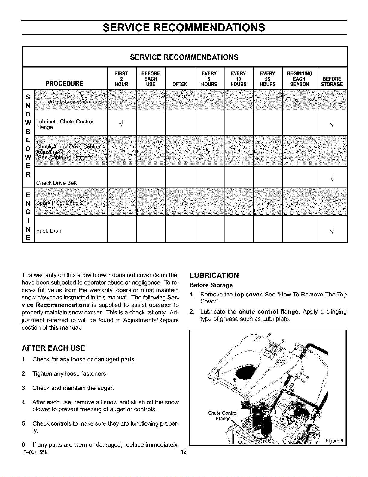
The warranty on this snow blower does not cover items that
have been subjected to operator abuse or negligence. Tore-
ceive full value from the warranty, operator must maintain
snow blower as instructed in this manual. The following Ser-
vice Recommendations is supplied to assist operator to
properly maintain snow blower. This isa check list only. Ad-
justment referred to will be found in Adjustments/Repairs
section of this manual.
LUBRICATION
Before Storage
1. Remove the top cover. See "How To Remove The Top
Cover".
2. Lubricate the chute control flange. Apply a clinging
type of grease such as Lubriplate.
AFTER EACH USE
1. Check for any loose or damaged parts.
2. Tighten any loose fasteners.
3. Check and maintain the auger.
4. After each use, remove all snow and slush offthe snow
blower to prevent freezing of auger or controls.
5. Check controlsto make sure they are functioning proper-
ly.
6. If any parts are worn or damaged, replace immediately.
F-001155M 12
Chute Control
Figure 5
CUSTOMER RESPONSIBILITIES
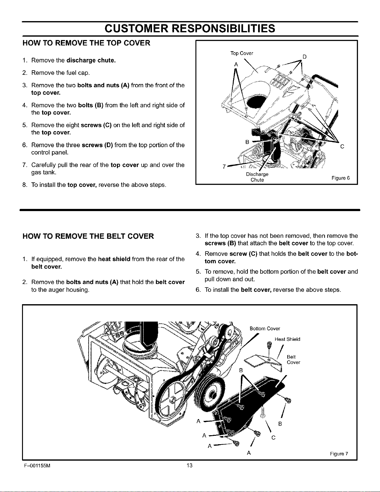
HOW TO REMOVE THE TOP COVER
1. Remove the discharge chute.
2. Remove the fuel cap.
3. Remove the two bolts and nuts (A) from the front of the
top cover.
4. Remove the two bolts (B) from the left and right side of
the top cover.
5. Remove the eight screws (C) on the left and right side of
the top cover.
6. Remove the three screws (D) from the top portion of the
control panel.
7. Carefully pull the rear of the top cover up and over the
gas tank.
8. To install the top cover, reverse the above steps.
TopCover D
A
B
7
Discharge
Chute
C
Figure 6
HOW TO REMOVE THE BELT COVER
1. If equipped, remove the heat shield from the rear of the
belt cover.
2. Remove the bolts and nuts (A) that hold the belt cover
to the auger housing.
3. If the top cover has not been removed, then remove the
screws (B) that attach the belt cover to the top cover.
4. Remove screw (C) that holds the belt cover to the bot-
tom cover.
5. To remove, hold the bottom portion of the belt cover and
pull down and out.
6. To install the belt cover, reverse the above steps.
Bottom Cover
Heat Shield
Belt
Cover
A
A
A
B
C
Figure 7
F-001155M 13
ADJUSTMENT/REPAIR
_hb WARNING: To prevent accidental starting when
making any adjustments or repairs, always dis-
connect the spark plug wire and place it where
it cannot make contact with the spark plug.
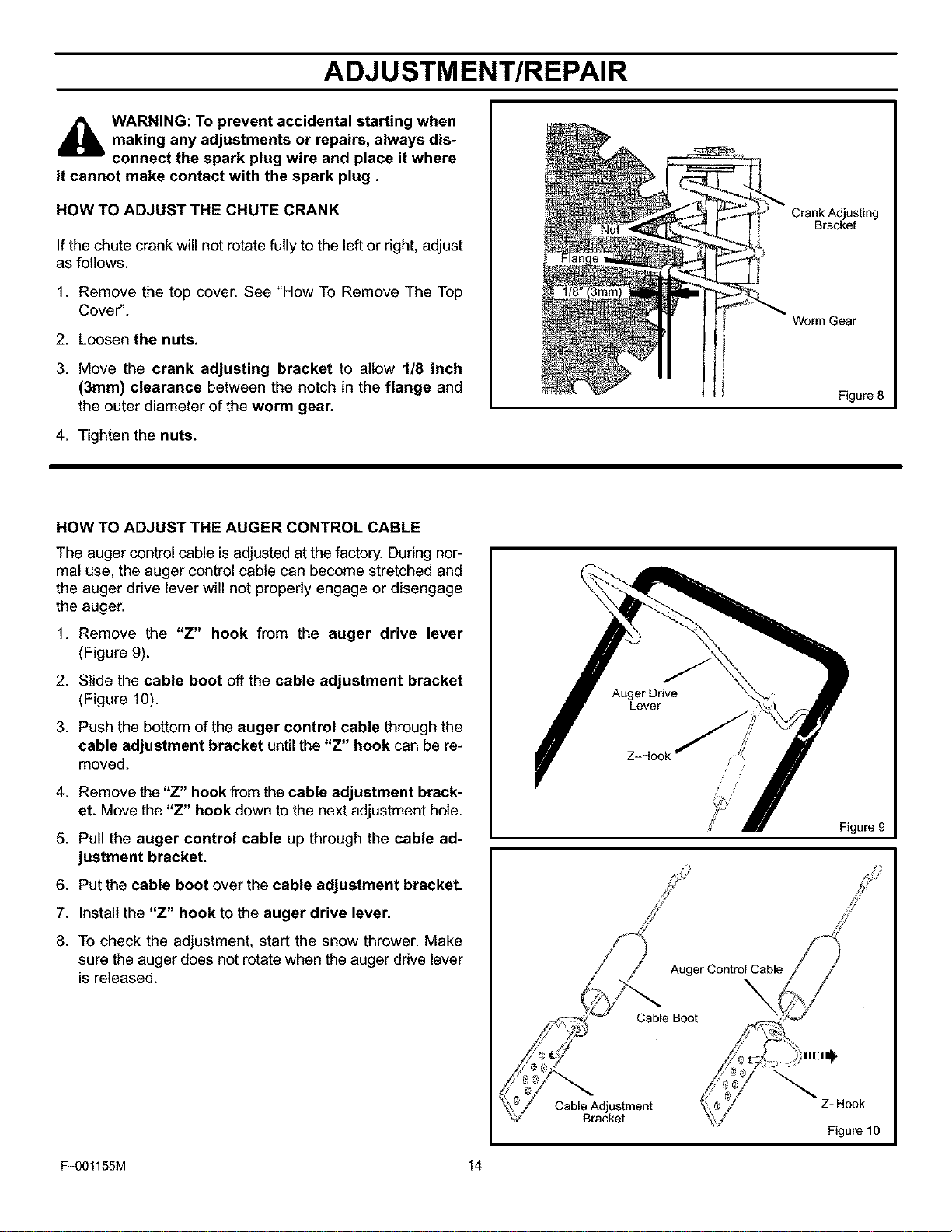
HOW TO ADJUST THE CHUTE CRANK
If the chute crank will not rotate fully to the left or right, adjust
as follows.
1. Remove the top cover. See "How To Remove The Top
Cover".
2. Loosen the nuts.
3. Move the crank adjusting bracket to allow 1/8 inch
(3mm) clearance between the notch in the flange and
the outer diameter of the worm gear.
4. Tighten the nuts.
Crank Adjusting
Bracket
Worm Gear
Figure 8
HOW TO ADJUST THE AUGER CONTROL CABLE
The auger control cable is adjusted at the factory. During nor-
mal use, the auger control cable can become stretched and
the auger drive lever will not properly engage or disengage
the auger.
1. Remove the "Z" hook from the auger drive lever
(Figure 9).
2. Slide the cable boot off the cable adjustment bracket
(Figure 10).
3. Push the bottom of the auger control cable through the
cable adjustment bracket until the "Z" hook can be re-
moved.
4. Remove the"Z" hook from the cable adjustment brack-
et. Move the "Z" hook down to the next adjustment hole.
5. Pull the auger control cable up through the cable ad-
justment bracket.
6. Put the cable boot over the cable adjustment bracket.
7. Install the "Z" hook to the auger drive lever.
8. To check the adjustment, start the snow thrower. Make
sure the auger does not rotate when the auger drive lever
is released.
Lever
_' Figure 9
Z_
Auger Control Cable
\
Cable Boot
Cable Adjustment
Bracket
Z-Hook
Figure 10
F-001155M 14
ADJUSTMENT/REPAIR
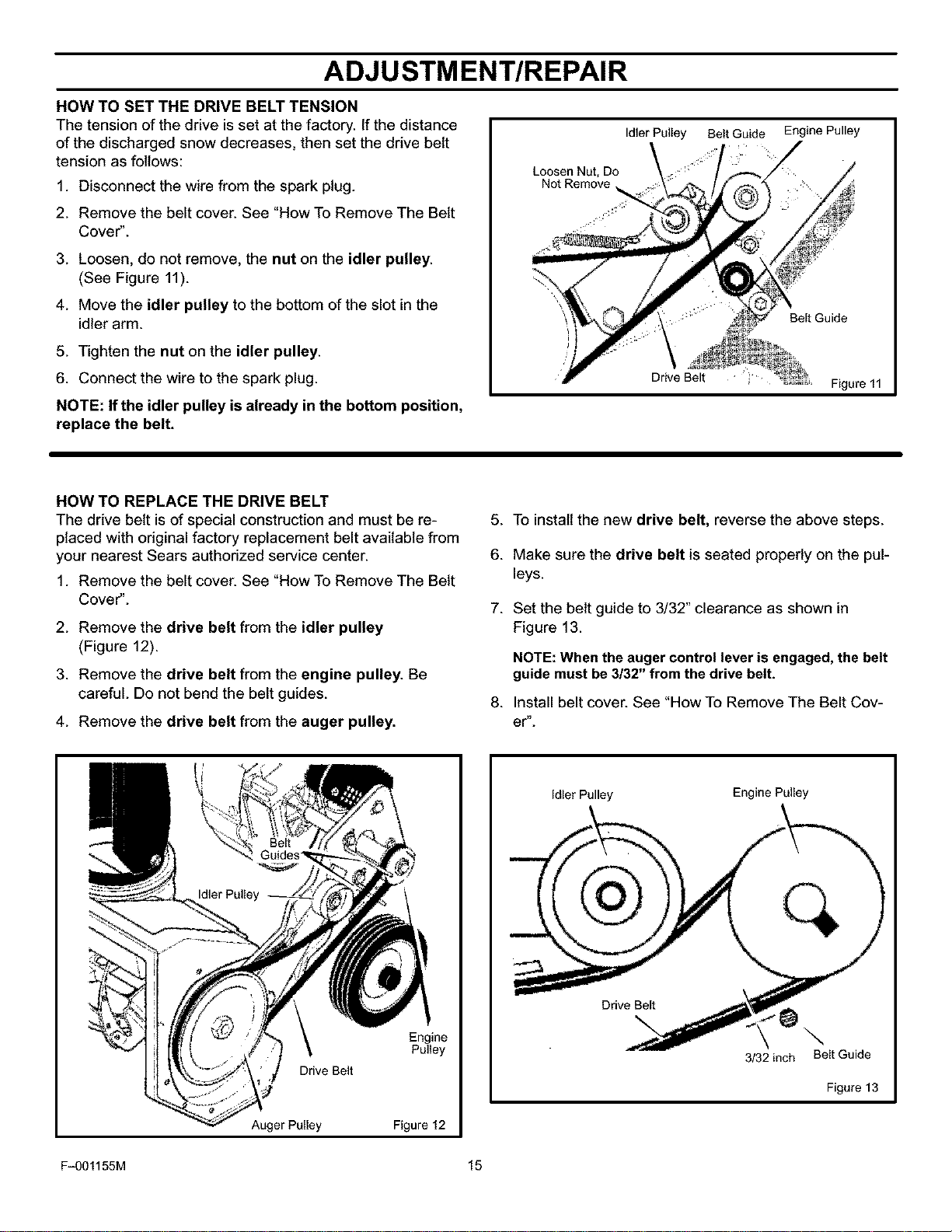
HOW TO SET THE DRIVE BELT TENSION
The tension of the drive is set at the factory. If the distance
of the discharged snow decreases, then set the drive belt
tension as follows:
1. Disconnect the wire from the spark plug.
2. Remove the belt cover. See "How To Remove The Belt
Cover".
3. Loosen, do not remove, the nut on the idler pulley.
(See Figure 11).
4. Move the idler pulley to the bottom of the slot in the
idler arm.
5. Tighten the nut on the idler pulley.
6. Connect the wire to the spark plug.
NOTE: If the idler pulley is already in the bottom position,
replace the belt.
Idler Pulley
Loosen Nut, Do
Not Remove
Belt Guide Engine Pulley
Belt Guide
Figure 11
HOW TO REPLACE THE DRIVE BELT
The drive belt is of special construction and must be re-
placed with original factory replacement belt available from
your nearest Sears authorized service center.
1. Remove the belt cover. See "How To Remove The Belt
Cover".
2. Remove the drive belt from the idler pulley
(Figure 12).
3. Remove the drive belt from the engine pulley. Be
careful. Do not bend the belt guides.
4. Remove the drive belt from the auger pulley.
5. To install the new drive belt, reverse the above steps.
6. Make sure the drive belt is seated properly on the pul-
leys.
7. Set the belt guide to 3/32" clearance as shown in
Figure 13.
NOTE: When the auger control lever is engaged, the belt
guide must be 3/32" from the drive belt.
8. Install belt cover. See "How To Remove The Belt Cov-
er".
Engine
Pulley
Drive Belt
Auger Pulley Figure 12
Idler Pulley Engine Pulley
Drive Belt
\
3/32 inch
Belt Guide
Figure 13
F-001155M 15
ADJUSTMENT/REPAIR
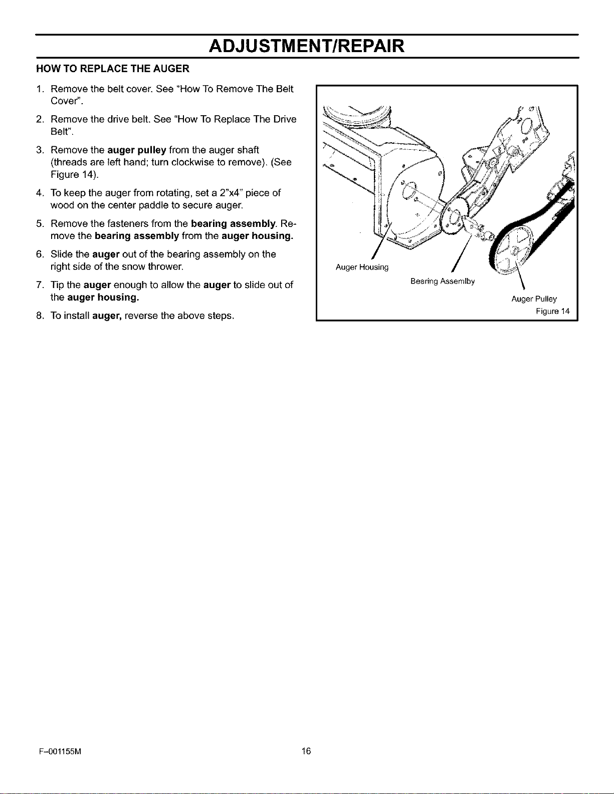
HOW TO REPLACE THE AUGER
1. Remove the belt cover. See "How To Remove The Belt
Cover".
2. Remove the drive belt. See "How To Replace The Drive
Belt".
3. Remove the auger pulley from the auger shaft
(threads are left hand; turn clockwise to remove). (See
Figure 14).
4. To keep the auger from rotating, set a 2"x4" piece of
wood on the center paddle to secure auger.
5. Remove the fasteners from the bearing assembly. Re-
move the bearing assembly from the auger housing.
6. Slide the auger out of the bearing assembly on the
right side of the snow thrower.
7. Tip the auger enough to allow the auger to slide out of
the auger housing.
8. To install auger, reverse the above steps.
Auger Housing
Bearing Assemlby
Auger Pulley
Figure 14
F-001155M 16
ADJUSTMENT/REPAIR
TO ADJUST THE CARBURETOR
The carburetor is not adjustable. Engine performance
should not be affected at altitudes up to 7,000 feet. For
operation at higher elevations, contact your nearest Sears
Store.
IMPORTANT: Never tamper with the engine governor,
which is factory set for proper engine speed. Over-speed-
ing the engine above the factory high speed setting can be
dangerous. If the engine-governed high speed needs an
adjustment, contact an authorized Sears Service Center.
They have the proper equipment and experience to make
any necessary adjustments.
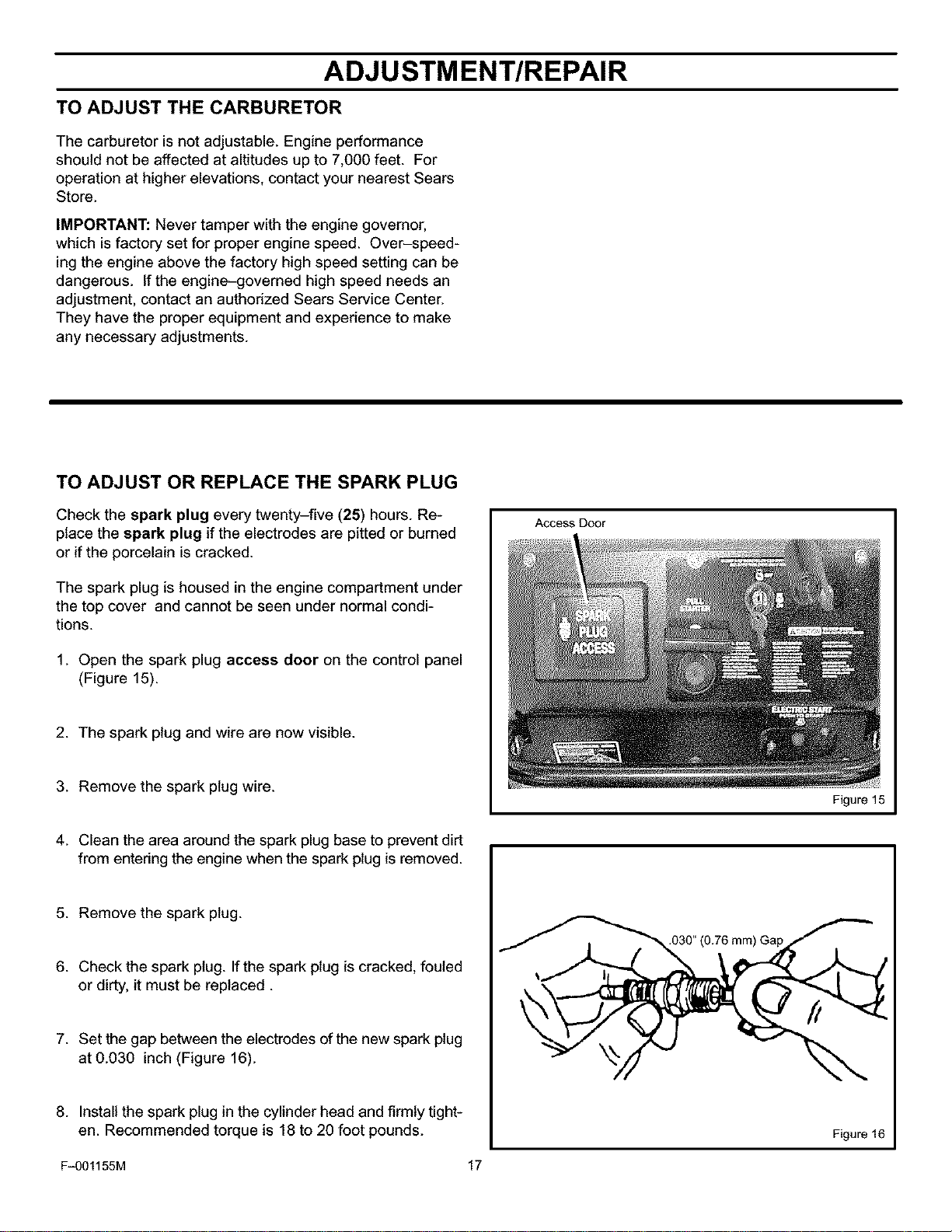
TO ADJUST OR REPLACE THE SPARK PLUG
Check the spark plug every twenty-five (25) hours. Re-
place the spark plug if the electrodes are pitted or burned
or if the porcelain is cracked.
The spark plug is housed in the engine compartment under
the top cover and cannot be seen under normal condi-
tions.
1. Open the spark plug access door on the control panel
(Figure 15).
2. The spark plug and wire are now visible.
3. Remove the spark plug wire.
Access Door
Figure 15
4. Clean the area around the spark plug base to prevent dirt
from entering the engine when the spark plug is removed.
5. Remove the spark plug.
6. Check the spark plug. If the spark plug is cracked, fouled
or dirty, it must be replaced.
7. Set the gap between the electrodes of the new spark plug
at 0.030 inch (Figure 16).
8. Install the spark plug in the cylinder head and firmly tight-
en. Recommended torque is 18 to 20 foot pounds.
F-001155M 17
.030" (0.76 mm) Gap
Figure 16
STORAGE
OFF SEASON STORAGE
WARNING: Never store the engine, with fuel in 3.
the tank, indoors or in a poor ventilated enclo-
sure where fuel fumes could reach an open
flame, spark or pilot light as on a furnace, water heater,
clothes dryer, etc.
Handle gasoline carefully. It is highly flammable and
careless use could result In serious fire damage to your
person and/or property. 4.
Drain fuel into approved containers outdoors, away
from open flame. 5.
If the snow blower is to be stored for thirty (30) days or more
at the end of the snow season, the following steps are
recommended to prepare your snow blower for storage.
NOTE: Gasoline must be removed or treated to prevent
gum deposits from forming in the tank, filter, hose, and
carburetor during storage.
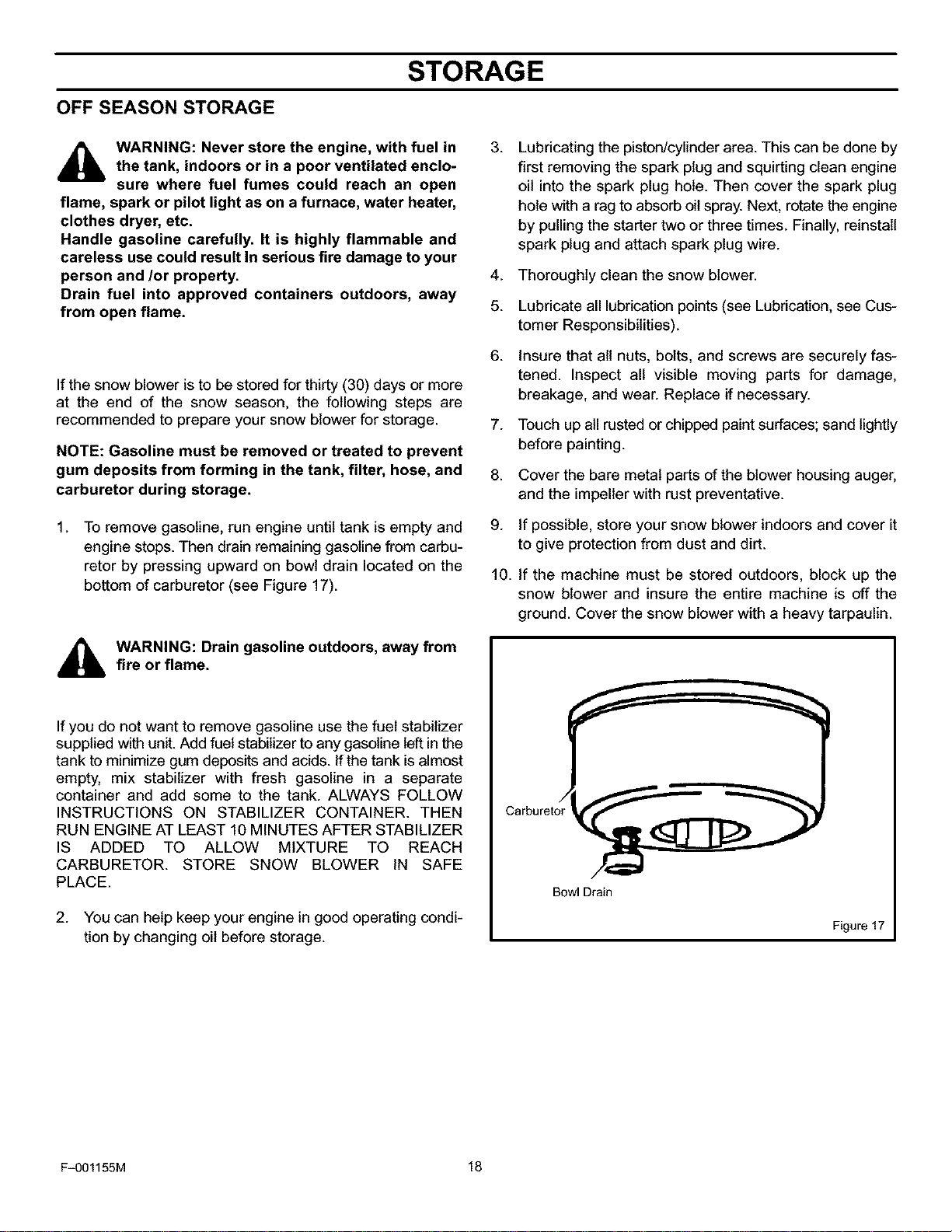
1. To remove gasoline, run engine until tank is empty and
engine stops. Then drain remaining gasoline from carbu-
retor by pressing upward on bowl drain located on the
bottom of carburetor (see Figure 17).
_lb ARNING: Drain gasoline outdoors, away fromfire or flame.
If you do not want to remove gasoline use the fuel stabilizer
supplied with unit. Add fuel stabilizer to any gasoline left in the
tank to minimize gum deposits and acids. If the tank is almost
empty, mix stabilizer with fresh gasoline in a separate
container and add some to the tank. ALWAYS FOLLOW
INSTRUCTIONS ON STABILIZER CONTAINER. THEN
RUN ENGINE AT LEAST 10 MINUTES AFTER STABILIZER
IS ADDED TO ALLOW MIXTURE TO REACH
CARBURETOR. STORE SNOW BLOWER iN SAFE
PLACE.
2. You can help keep your engine in good operating condi-
tion by changing oil before storage.
6.
7.
8.
9.
10.
Lubricating the piston/cylinder area. This can be done by
first removing the spark plug and squirting clean engine
oil into the spark plug hole. Then cover the spark plug
hole with a rag to absorb oil spray. Next, rotate the engine
by pulling the starter two or three times. Finally, reinstall
spark plug and attach spark plug wire.
Thoroughly clean the snow blower.
Lubricate all lubrication points (see Lubrication, see Cus-
tomer Responsibilities).
Insure that all nuts, bolts, and screws are securely fas-
tened. Inspect all visible moving parts for damage,
breakage, and wear. Replace if necessary.
Touch up all rusted or chipped paint surfaces; sand lightly
before painting.
Cover the bare metal parts of the blower housing auger,
and the impeller with rust preventative.
If possible, store your snow blower indoors and cover it
to give protection from dust and dirt.
if the machine must be stored outdoors, block up the
snow blower and insure the entire machine is off the
ground. Cover the snow blower with a heavy tarpaulin.
Bowl Drain
Figure 17
F-001155M 18
TROUBLE SHOOTING CHART
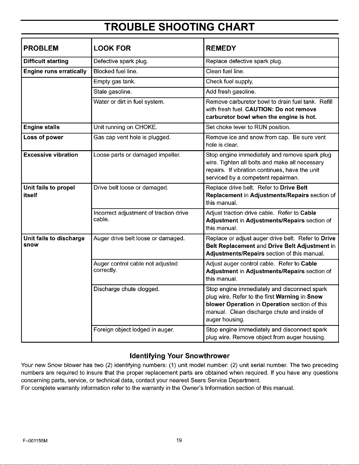
PROBLEM LOOK FOR REMEDY
Difficult starting Defective spark plug. Replace defective spark plug.
Engine runs erratically Blocked fuel line. Clean fuel line.
Empty gas tank. Check fuel supply,
Stale gasoline. Add fresh gasoline.
Water or dirt in fuel system. Remove carburetor bowl to drain fuel tank. Refill
with fresh fuel. CAUTION: Do not remove
carburetor bowl when the engine is hot.
Engine stalls Unit running on CHOKE. Set choke lever to RUN position.
Loss of power Gas cap vent hole is plugged. Remove ice and snow from cap. Be sure vent
hole is clear.
Excessive vibration Loose parts or damaged impeller. Stop engine immediately and remove spark plug
wire. Tighten all bolts and make all necessary
repairs. If vibration continues, have the unit
serviced by a competent repairman.
Unit fails to propel Drive belt loose or damaged. Replace drive belt. Refer to Drive Belt
itself Replacement in Adjustments/Repairs section of
this manual.
Incorrect adjustment of traction drive Adjust traction drive cable. Refer to Cable
cable. Adjustment in Adjustments/Repairs section of
this manual.
Unit fails to discharge Auger drive belt loose or damaged. Replace or adjust auger drive belt. Refer to Drive
snow Belt Replacement and Drive Belt Adjustment in
Adjustments/Repairs section of this manual.
Auger control cable not adjusted Adjust auger control cable. Refer to Cable
correctly. Adjustment in Adjustments/Repairs section of
this manual.
Discharge chute clogged. Stop engine immediately and disconnect spark
plug wire. Refer to the first Warning in Snow
blower Operation in Operation section of this
manual. Clean discharge chute and inside of
auger housing.
Foreign object lodged in auger. Stop engine immediately and disconnect spark
plug wire. Remove object from auger housing.
Identifying Your Snowthrower
Your new Snow blower has two (2) identifying numbers: (1) unit model number: (2) unit serial number. The two preceding
numbers are required to insure that the proper replacement parts are obtained when required. If you have any questions
concerning parts, service, or technical data, contact your nearest Sears Service Department.
For complete warranty information refer to the warranty in the Owner's Information section of this manual.
F-001155M 19
CRAFTSMAN21"SNOWBLOWERC950-52935-1
CRAFTSMAN21" CHASSE-NEIGEC950-52935-1
REPAIRPARTS
PII_CESDERECHANGE
ENGINE/ MOTEUR
10
12
11
12
11
25
F-001155M
42
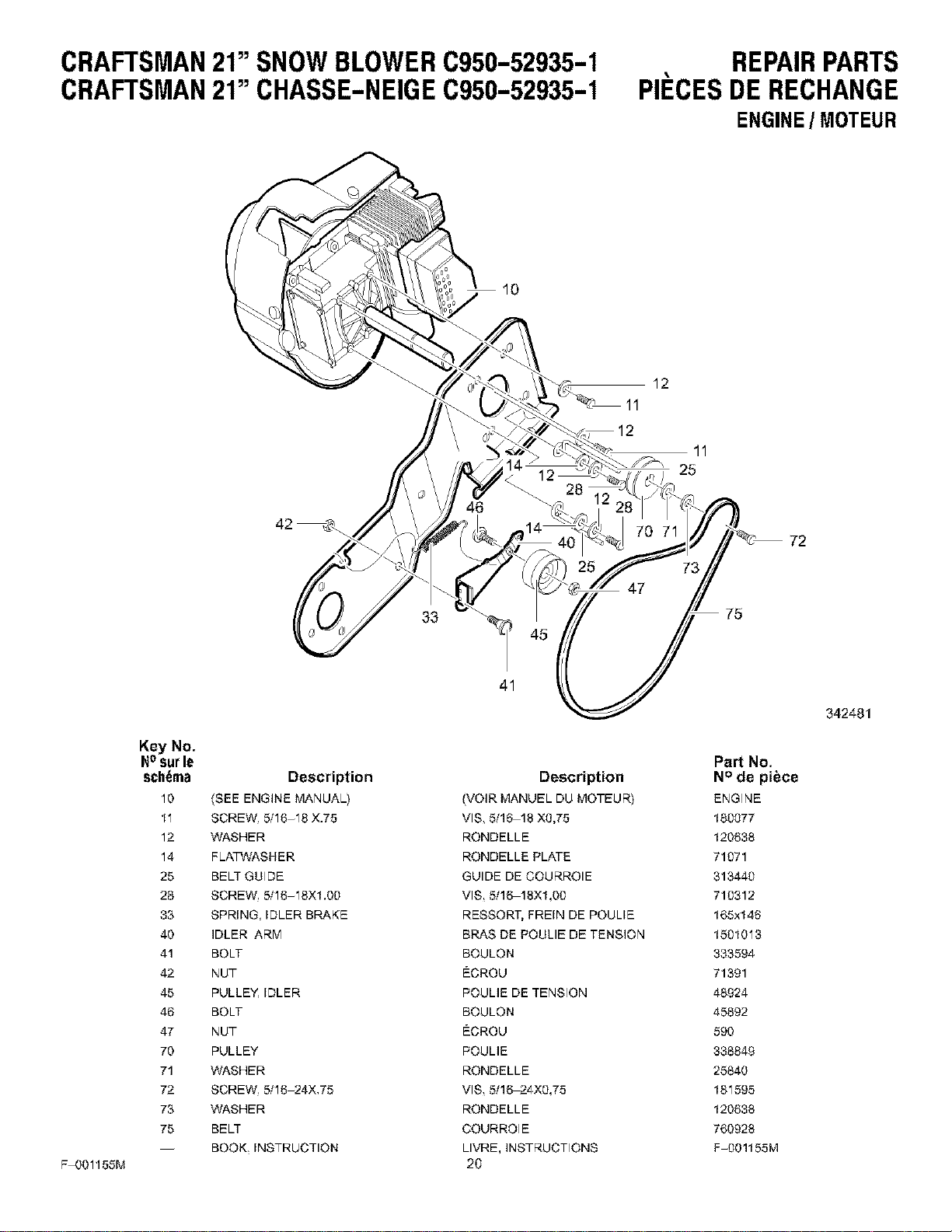
Key No.
Nosurle
schema Description
10 (SEE ENGINE MANUAL)
11 SCREW. 5f16-18 X.75
12 WASHER
14 FLATWASHER
25 BELT GUIDE
23 SCREW, 5/16-18X1.00
33 SPRING, IDLER BRAKE
40 IDLER ARM
41 BOLT
42 NUT
45 PULLEY, IDLER
46 BOLT
47 NUT
70 PULLEY
71 WASHER
72 SCREW, 5/16-24X,75
73 WASHER
75 BELT
-- BOOK INSTRUCTION
33
41
Description
_VOIR MANUEL DU MOTEUR)
VlS 511_18 X0,75
RONDELLE
RONDELLE PLATE
GUIDE DE COURROIE
VlS 511_18X1,00
RESSORT, FREIN DE POULIE
BRAS DE POULIE DE TENSION
BOULON
ECROU
ROULIE DE TENSION
BOULON
ECROU
ROULIE
RONDELLE
VlS, 5/1_24X0,75
RONDELLE
COURROIE
LIVRE, INSTRUCTIONS
2O
72
75
342481
Part No.
N° de pibce
ENGINE
180077
120638
71071
313440
710312
165xl 48
1501013
333594
71391
48924
45892
590
338849
25840
181595
120638
760928
F-OO1155M
CRAFTSMAN21"SNOWBLOWERC950-52935-1
CRAFTSMAN21" CHASSE-NEIGEC950-52935-1
REPAIRPARTS
PII_CESDERECHANGE
FRAMECOMPONENTS/ BATI
111
92
342434
F-001155M
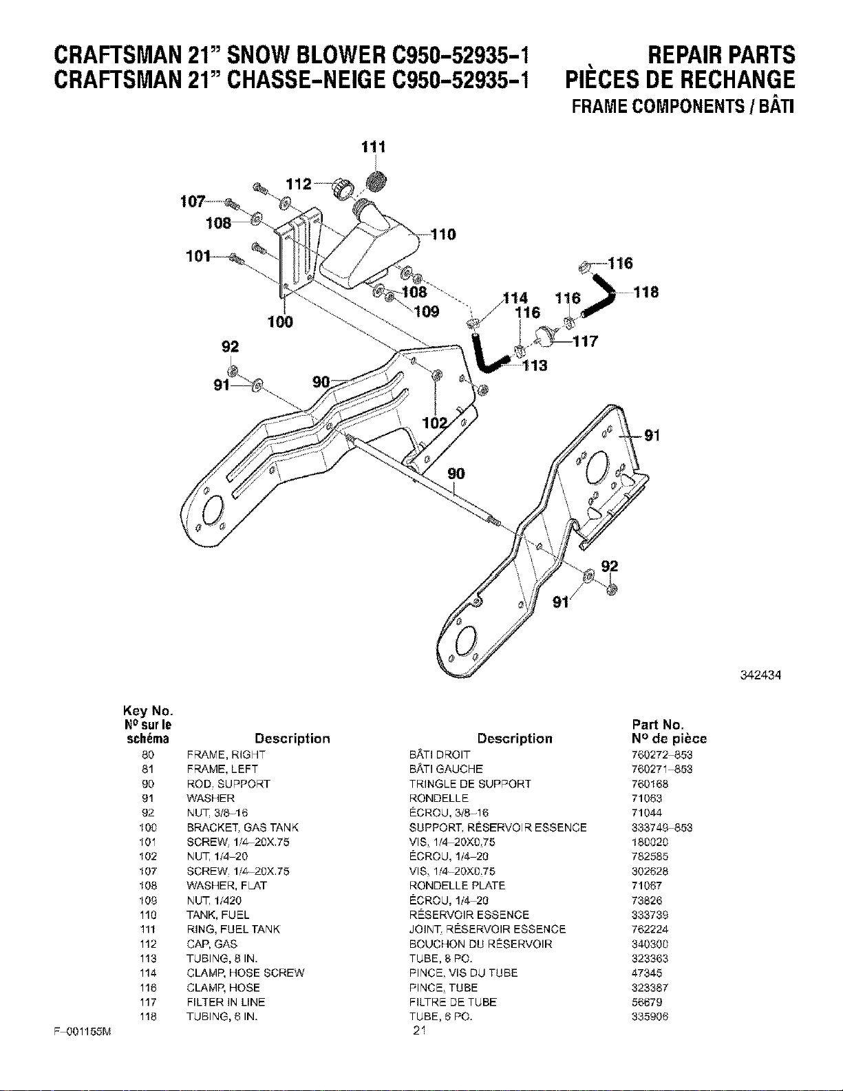
Key No.
NOsur le
schema
60
61
90
91
92
100
101
102
107
108
108
110
111
112
113
114
118
117
118
Description
FRAME, RIGHT
FRAME, LEFT
ROD SUPPORT
WASHER
NUT 3/8-16
BRACKET. GAS TANK
SCREW. 1/_20X.75
NUT 1/4-20
SCREW. 1f_20X.75
WASHER, FLAT
NUT 1/420
TANK, FUEL
RING, FUEL TANK
CAP, GAS
TUBING, 8 IN.
CLAMP, HOSE SCREW
CLAMP, HOSE
FILTER IN LINE
TUBING, 6 IN.
Description
BATI DROIT
BATI GAUCHE
TRINGLE DE SUPPORT
RONDELLE
ECROU, 3/8-16
SUPPORT. RI_SERVOIR ESSENCE
VlS 1f4-20X0 75
ECROU, 1/4-20
VlS 1f4-20X0,75
RONDELLE PLATE
ECROU, 1/4-20
RESERVOIR ESSENCE
JOINT. RESERVOIR ESSENCE
BOUCHON DU RESERVOIR
TUBE, 8 PO.
PlNCE VIS DU TUBE
PlNCE TUBE
FILTRE DE TUBE
TUBE, 8 PO.
21
Part No.
N° de piece
760272-853
760271-853
760168
71063
71044
333749_853
180020
782585
302628
71067
73826
333739
762224
340300
323363
47345
323367
56879
335908
CRAFTSMAN21"SNOWBLOWERC950-52935-1
CRAFTSMAN21" CHASSE-NEIGEC950-52935-1
REPAIRPARTS
PII_CESDERECHANGE
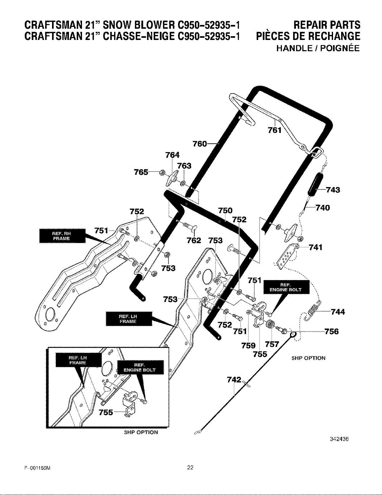
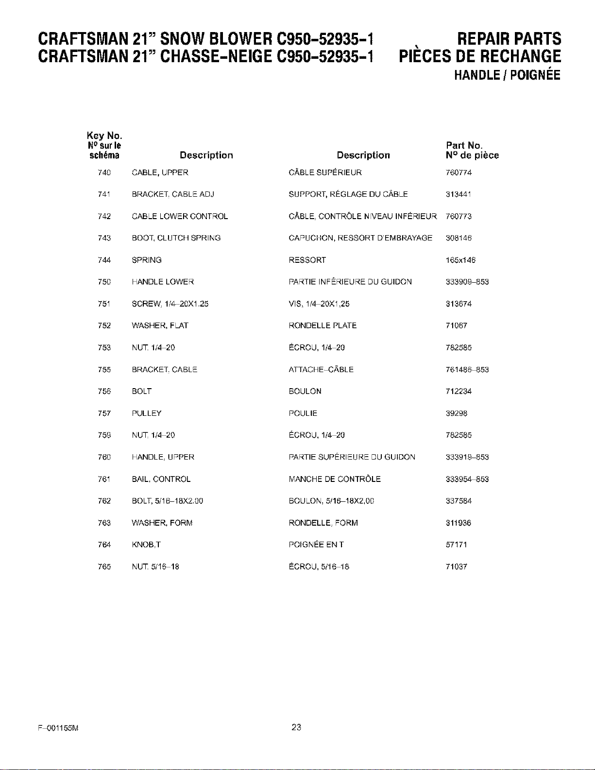
HANDLE / POIGNI_E
764
763
752 750
752
753
762 753
752
3NP OPTION
759
755
5HP OPTION
342436
F_OO1155M 22
CRAFTSMAN21"SNOWBLOWERC950-52935-1
CRAFTSMAN21" CHASSE-NEIGEC950-52935-1
REPAIRPARTS
PII_CESDERECHANGE
HANDLE/ POIGNEE
Key No.
Nosurle
schema Description
740 CABLE, UPPER
741 BRACKET, CABLE ADJ
742 CABLE LOWER CONTROL
743 BOOT, CLUTCH SPRING
744 SPRING
780 HANDLE LOWER
781 SCREW, 114 20X1,25
752 WASHER, FLAT
753 NUT 1/4-20
755 BRACKET, CABLE
755 BOLT
757 PULLEY
759 NUT 1/4-20
760 HANDLE, UPPER
761 BAIL, CONTROL
762 BOLT, 5/16-18X2.,00
763 WASHER, FORM
764 KNOB,T
765 NUT 5f16-18
Part No.
Description N° de piece
CABLE SUPERIEUR 760774
SUPPORT, RI_GLAGE DU CABLE 313441
CABLE CONTROLE NIVEAU ]NFERIEUR 760773
CARUCHON, RESSORT D'EMBRAYAGE 308145
RESSORT 165xl 45
RARTIE INFERIEURE DU GUIDON 333909-853
VlS 1f_20X1 25 313674
RONDELLE PLATE 71067
ECROU, 1/4-20 782585
ATTACH EqSABLE 761486_53
BOULON 712234
POULIE 39298
ECROU, 1/4-20 782585
RARTIE SUPERIEURE DU GUIDON 333918-853
MANCHE DE CONTROLE 333954453
BOULON, 5/16-18X2,00 337584
RONDELLE FORM 311936
ROIGNEE EN T 57171
ECROU, 5/16-18 71037
F-001155M 23
CRAFTSMAN21"SNOWBLOWERC950-52935-1
CRAFTSMAN21" CHASSE-NEIGEC950-52935-1
511
2
REPAIRPARTS
PII_CESDERECHANGE
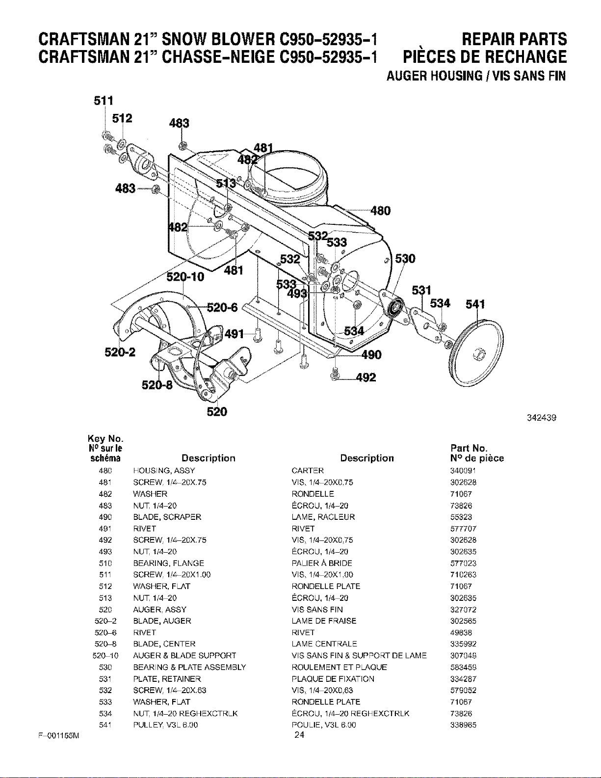
AUGERHOUSING/VIS SANS FIN
53O
!
F-001156M
520
Key No.
Nosurle
schema Description
460 HOUSING, ASSY
481 SCREW, 1/4 20X,75
462 WASHER
483 NUT 1f4-20
490 BLADE, SCRAPER
491 RIVET
492 SCREW, 1/4 20X,75
493 NUT 1f4-20
510 BEARING, FLANGE
511 SCREW, 1/4 20X1,00
512 WASHER, FLAT
513 NUT 1f4-20
520 AUGER, ASSY
520-2 BLADE, AUGER
520-6 RIVET
5208 BLADE, CENTER
520-10 AUGER & BLADE SUPPORT
530 BEARING & PLATE ASSEMBLY
531 PLATE, RETAINER
532 SCREW, 1f4 20X.63
533 WASHER, FLAT
534 NUT 1/,420 REGHEXCTRLK
541 PULLEY, V3L 6,00
Description
CARTER
VlS 1f,420X0,75
RONDELLE
ECROU, 1/4-20
LAME, RACLEUR
RIVET
VlS 1f,420X075
ECROU, 1/4-20
PALER/_. BRIDE
VlS 1f,420X1 O0
RONDELLE PLATE
ECROU, 1/4-20
VlS SANS FIN
LAME DE FF;ba.ISE
RIVET
LAME CENTRALE
VIS SANS FIN & SUPPORT DE LAME
ROULEMENT ET PLAQUE
PLAQUE DE FIXATION
VlS 1f,420X0 63
RONDELLE PLATE
ECROU, 1/,420 REGHEXCTRLK
POULIE, V3L 6,00
24
Part No.
N° de piece
340091
302628
71067
73826
55323
677707
302628
302635
677023
710263
71067
302635
327072
302565
49838
335992
307049
583459
334287
579052
71067
73826
338965
342439
CRAFTSMAN21"SNOWBLOWERC950-52935-1 REPAIRPARTS
CRAFTSMAN21" CHASSE-NEIGEC950-52935-1 PII_CESDERECHANGE
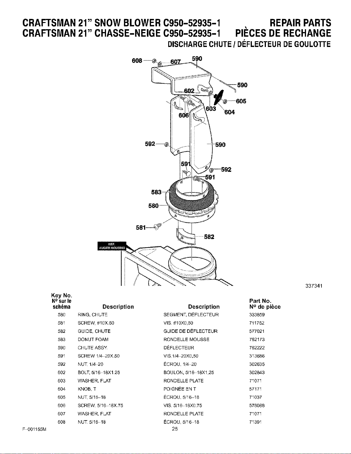
DISCHARGECHUTE/ DEFLECTEURDEGOULOTTE
F-001158M
Key No.
NOsurle Part No.
sch6ma Description Description N° de piece
560 RING, CHUTE SEG_'IENT, DEFLECTEUR 333659
581 SCREW, #10X,50 VIS, #10X0,50 711752
862 GUIDE, CHUTE GUIDE DE DEFLECTEUR 577021
863 DONUT FOAM RONDELLE MOUSSE 762173
890 CHUTE ASSY, DEFLECTEUR 762222
591 SCREW 1/'4_20X,50 VIS,II4 20X0,50 313686
592 NUT 1/4-20 ECRQU, 1/'4-20 302635
602 BOLT, 5t16-16X1,25 BQULON, 5/16 16X1,25 302843
603 WASHER, FLAT RONDELLE PLATE 71071
604 KNOB, T POIGNEE EN T 57171
605 NUT 5/1618 ECRQU, 5/'16-18 71037
606 SCREW, 5f16-18X,75 VIS, 8/16 16X0,75 578088
607 WASHER, FLAT RONDELLE PLATE 71071
608 NUT 5/1618 ECRQU, 5/'16-18 71391
25
337341
CRAFTSMAN21"SNOWBLOWERC950-52935-1
CRAFTSMAN21" CHASSE-NEIGEC950-52935-1
REPAIRPARTS
PII_CESDERECHANGE
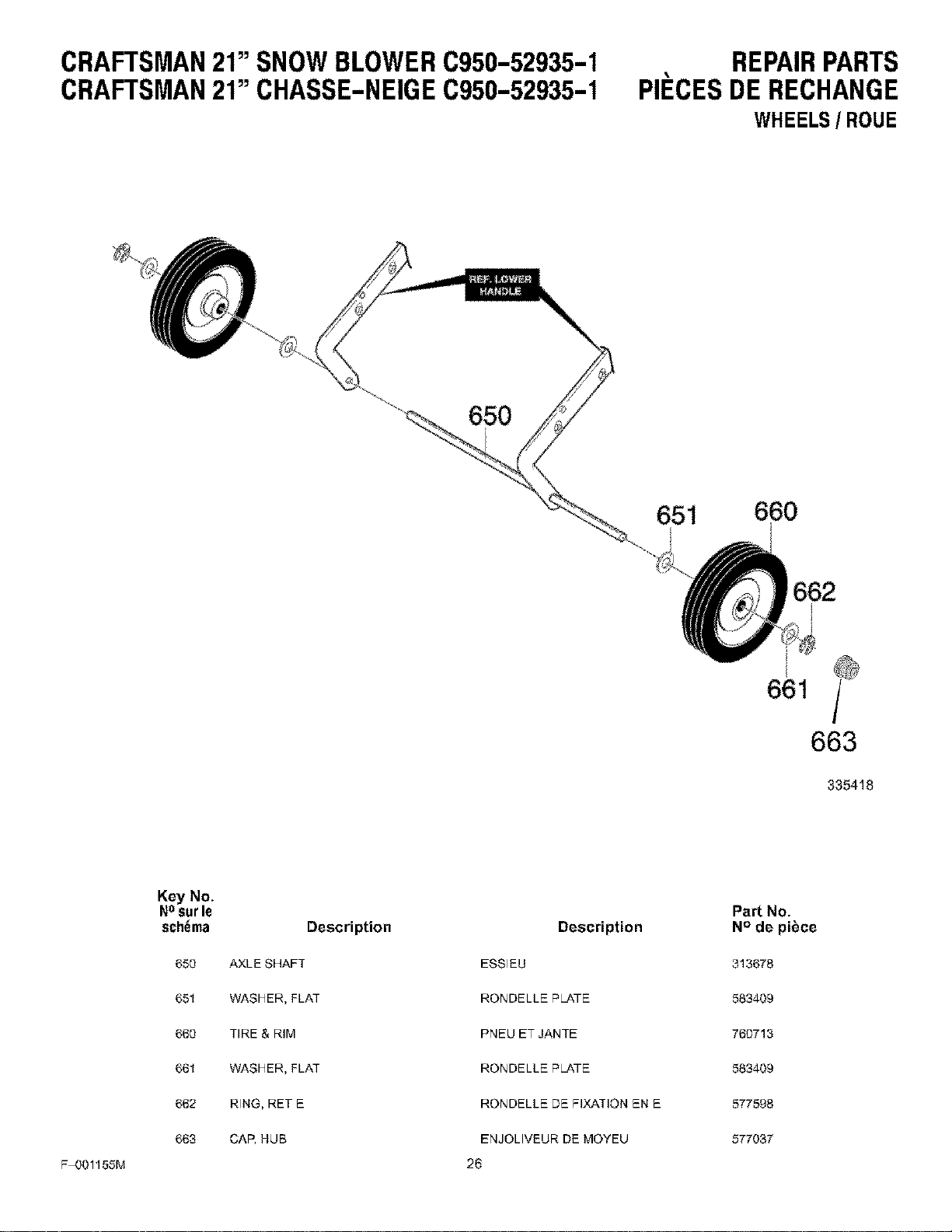
WHEELS/ ROUE
650
651 660
661
663
335418
F-OO1156M
Key No.
Nosurle
schema Description
650 AXLE SHAFT
651 WASHER, FLAT
660 TIRE & RIM
661 WASHER, FLAT
662 RING, RET E
663 CAR HUB
Description
ESSIEU
RONDELLE PLATE
PNEU ET JANTE
RONDELLE PLATE
RONDELLE DE FIXATION EN E
ENJOLIVEUR DE MOYEU
26
Part No.
N° de piece
313678
583409
760713
583409
577598
677037
CRAFTSMAN21"SNOWBLOWERC950-52935-1
CRAFTSMAN21" CHASSE-NEIGEC950-52935-1
REPAIRPARTS
PII_CESDERECHANGE
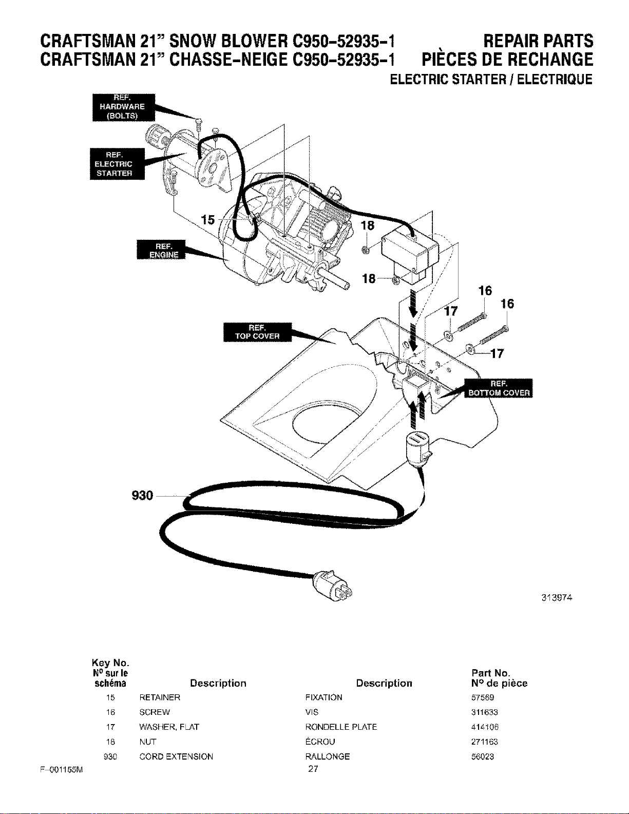
ELECTRICSTARTER/ ELECTRIQUE
//
)
16
16
313974
F-001156M
Key No.
N0surle
schema
15
16
17
18
930
Description
RETAINER
SCREW
WASHER, FL-&T
NUT
CORD EXTENSION
Description
FIXATION
VlS
RONDELLE PLATE
ECROU
RALLONGE
27
Pa_ No.
N° de pibce
57569
311633
414106
271163
56023
CRAFTSMAN21"SNOWBLOWERC950-52935-1
CRAFTSMAN21" CHASSE-NEIGEC950-52935-1
REPAIRPARTS
PII_CESDERECHANGE
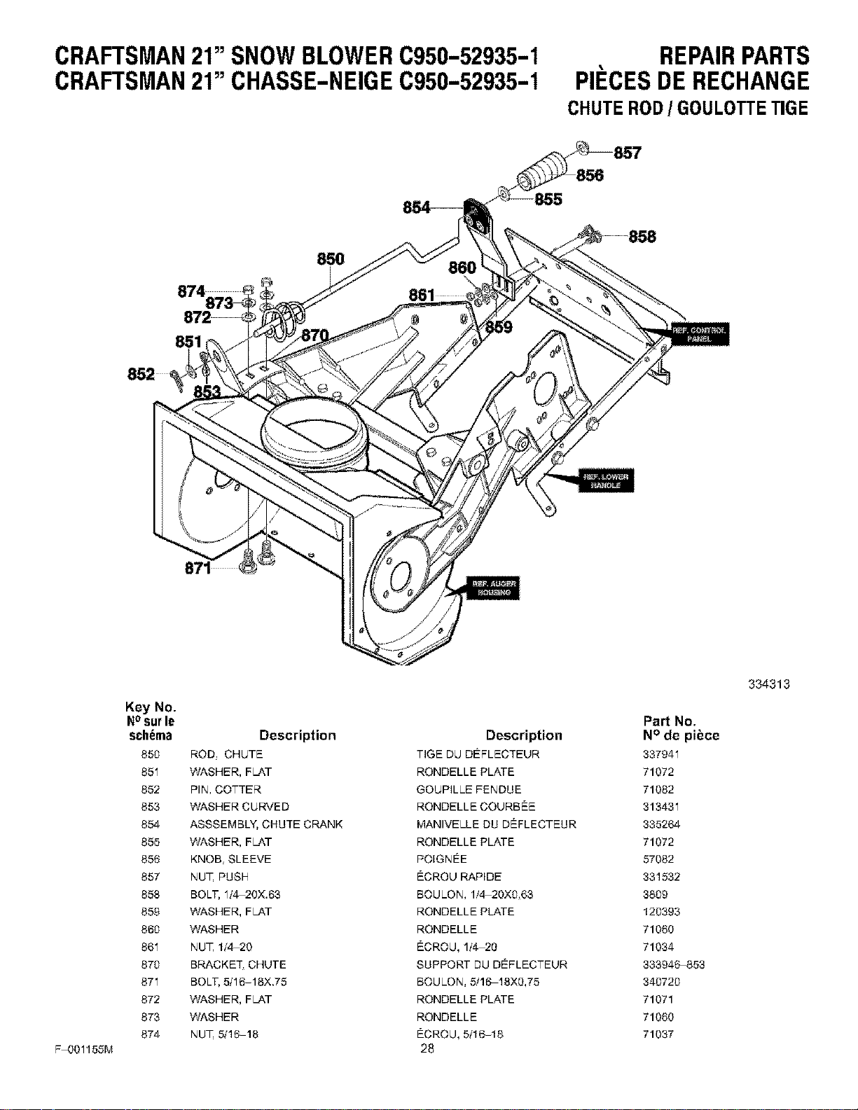
CHUTEROD/ GOULOTTETIGE
85O
851
F-001155M
Key No.
Nosurle
schema
850
851
852
853
854
855
856
857
858
859
860
861
870
871
872
873
874
Description
ROD CHUTE
WASHER, FL&T
PIN, COTTER
WASHER CURVED
ASSSEMBLY, CHUTE CRANK
WASHER, FL&T
KNOB, SLEEVE
NUT PUSH
BOLT, 114_20X.63
WASHER, FL&T
WASHER
NUT 1/4-20
BRACKET, CHUTE
BOLT, 5/16-18X.75
WASHER, FL&T
WASHER
NUT 5/16-18
Description
TiGE DU DEFLECTEUR
RONDELLE PLATE
GOUPiLLE FENDUE
RONDELLE COURBEE
MANIVELLE DU DEFLECTEUR
RONDELLE PLATE
POIGNEE
ECROU RAPIDE
BOULON, 1/,4 20X9,63
RONDELLE PLATE
RONDELLE
ECROU, 1/4-20
SUPPORT DU DEFLECTEUR
BOULON, 5/16-18X9,75
RONDELLE PLATE
RONDELLE
ECROU, 5t16-18
28
Part No.
N° de pibce
337941
71072
71082
313431
33526%
71072
57082
331532
3899
129393
71060
71034
333946_,53
349729
71071
71060
71037
334313
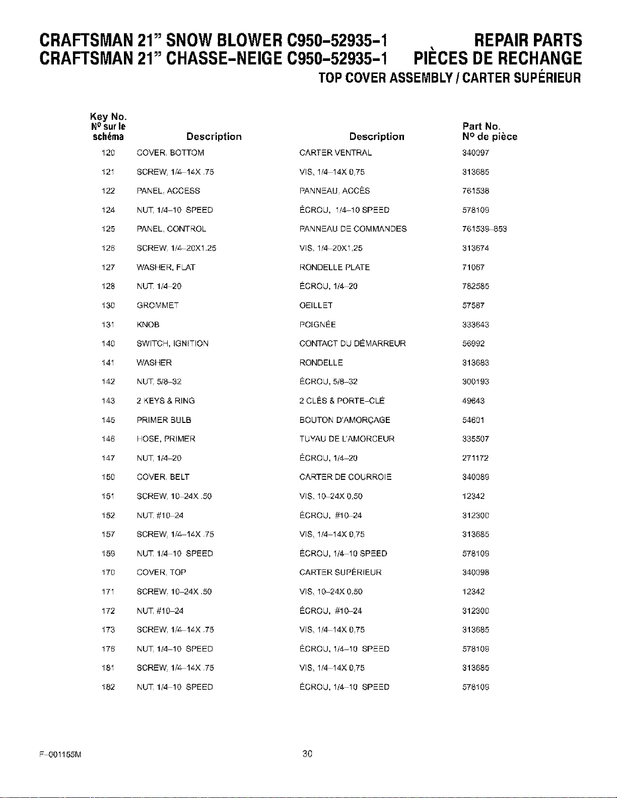
CRAFTSMAN21"SNOWBLOWERC950-52935-1 REPAIRPARTS
CRAFTSMAN21" CHASSE-NEIGEC950-52935-1 PII_CESDERECHANGE
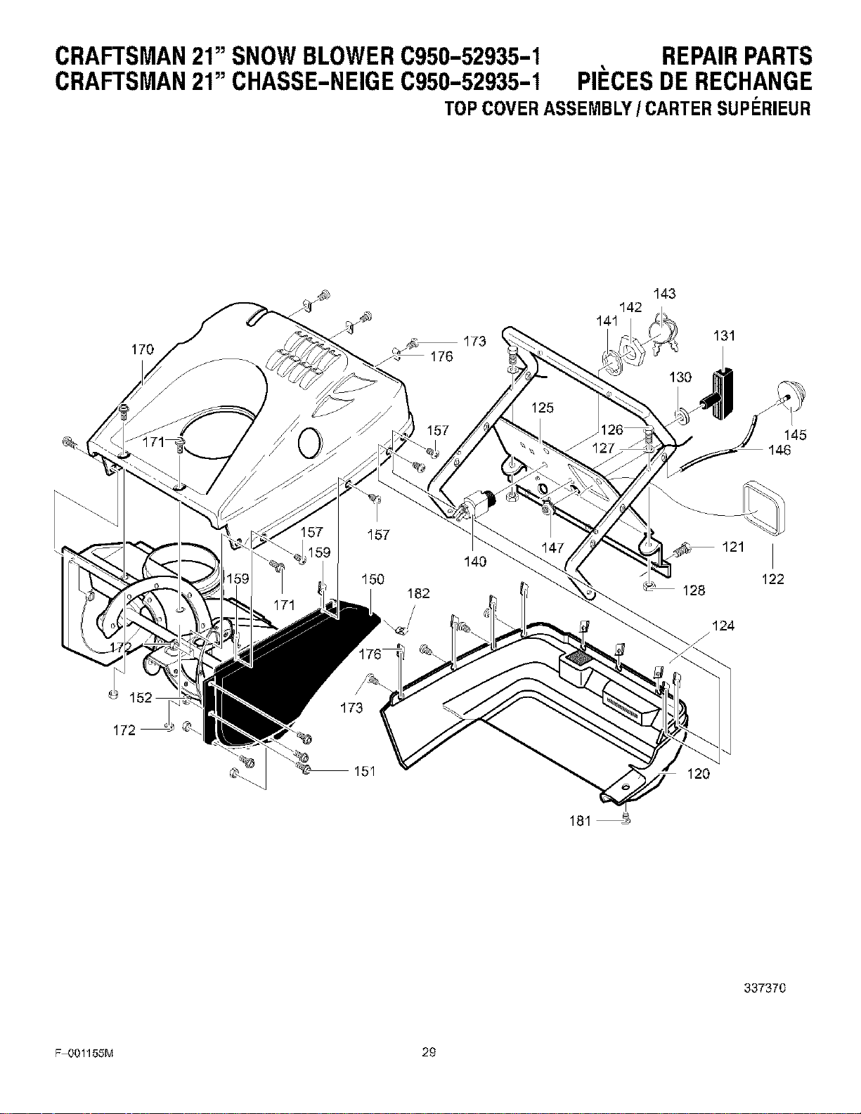
TOPCOVERASSEMBLY/CARTER SUPF:RIEUR
170
173
142
141
143
131
157
145
146
124
J
172
©\ 151 120
181
337370
F-OO1155M 29
CRAFTSMAN21"SNOWBLOWERC950-52935-1 REPAIRPARTS
CRAFTSMAN21" CHASSE-NEIGE0950-52935-1 PII CESDERECHANGE
TOPCOVERASSEMBLY/CARTER SUPERIEUR
Key No.
NOsurle Part No.
schema Description Description N° de piece
120 COVER, BOTTOM CARTER VENTRAL 340097
121 SCREW, lf4 14X .75 VlS, 11,414X 9,75 313685
122 PANEL, ACCESS F'ANNEAU, ACCES 761538
124 NUT 11,4 10 SPEED ECROU, 1/4_10 SPEED 576109
125 PANEL, CONTROL PANNEAU DE COMMANDES 761538-853
126 SCREW, 1f4 20X1.25 VlS, 1f,4 20X1,25 313674
127 WASHER, FLAT RONDELLE PLATE 71067
128 NUT 1/4-20 ECROU, 1/4-20 782585
130 GROMMET OEILLET 57587
131 KNOB POIGNEE 333643
140 SWITCH, IGNITION CONTACT DU DEMARREUR 56992
141 WASHER RONDELLE 313683
142 NUT 5/8-32 ECROU, 5/8-32 300193
143 2 KEYS & RING 2 CLES & PORTEJOLE 49643
145 PRIMER BULB BOUTON D'AMOR_AGE 54601
146 HOSE, PRIMER TUYAU DE L'AMORCEUR 335507
147 NUT 1/4-20 ECROU, 1/4-20 271172
150 COVER, BELT CARTER DE COURROIE 340089
151 SCREW, 10-24X ,50 VlS, 10-24X O,SO 12342
152 NUT #10-24 ECROU, #10-24 312300
157 SCREW, 1/4 14X ,75 VIS, 1/4-14X 0,75 313685
159 NUT 1f4-10 SPEED ECROU, 1/4-10 SPEED 576109
170 COVER, TOP CARTER SUPERIEUR 340098
171 SCREW, 10-24X ,50 VlS, 10-24X 0,50 12342
172 NUT #10-24 ECROU, #10-24 312300
173 SCREW, 1/4 14X ,75 VlS, 1f4-14X 0,75 313685
176 NUT 1f4-10 SPEED ECROU, 1/4-10 SPEED 576109
181 SCREW, lf4 14X .75 VlS, 1f4-14X 0,75 313685
182 NUT 114-10 SPEED ECROU, 1/4-10 SPEED 576109
F-001156M 30
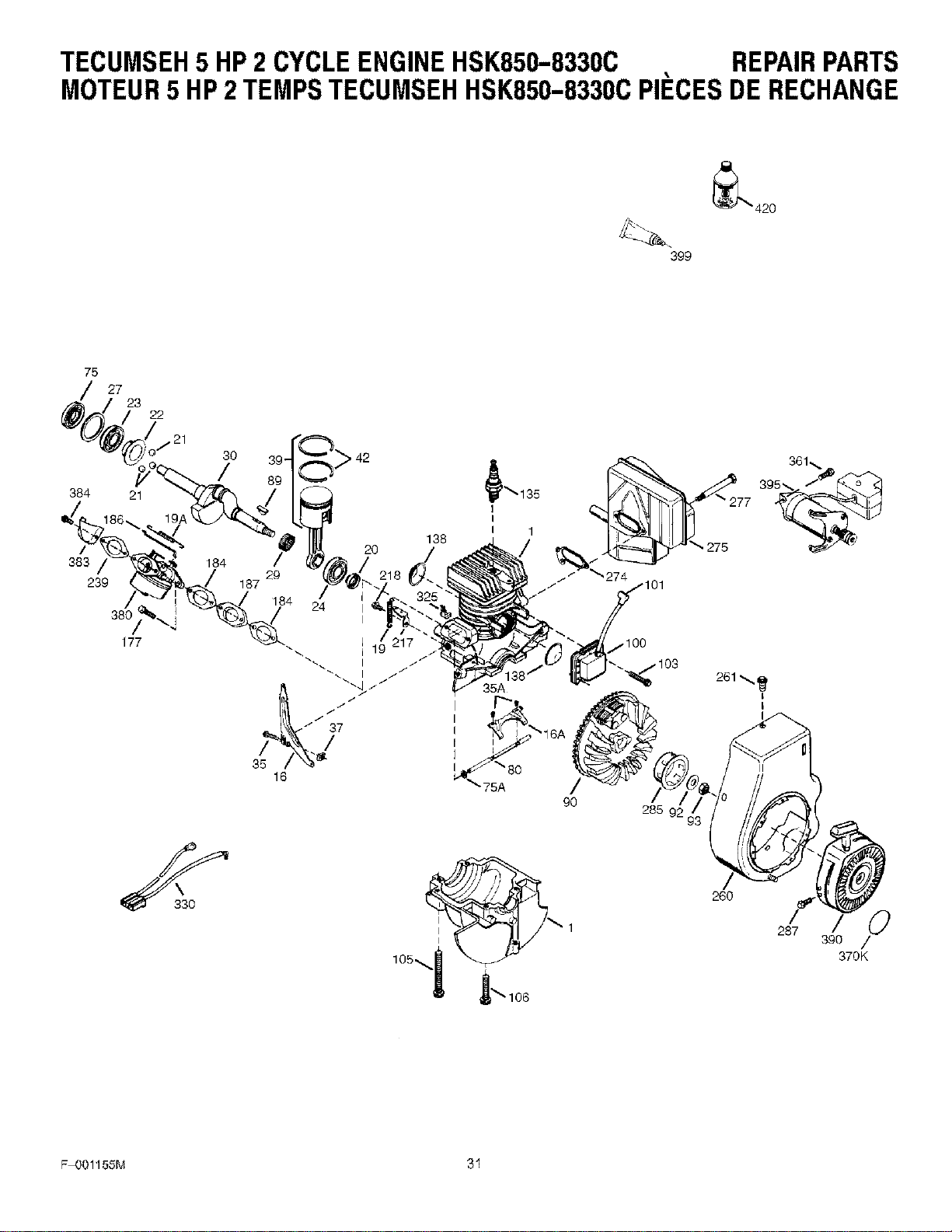
TECUMSEH5 HP2 CYCLEENGINEHSK850-8330C REPAIRPARTS
MOTEUR5 HP2TEMPSTECUMSEHHSK850-8330CPII_CESDERECHANGE
_"_ 420
399
75
/ 27
23
22
285 9
/
260
F/O
287
3go /
370K
F-OO1155M 31
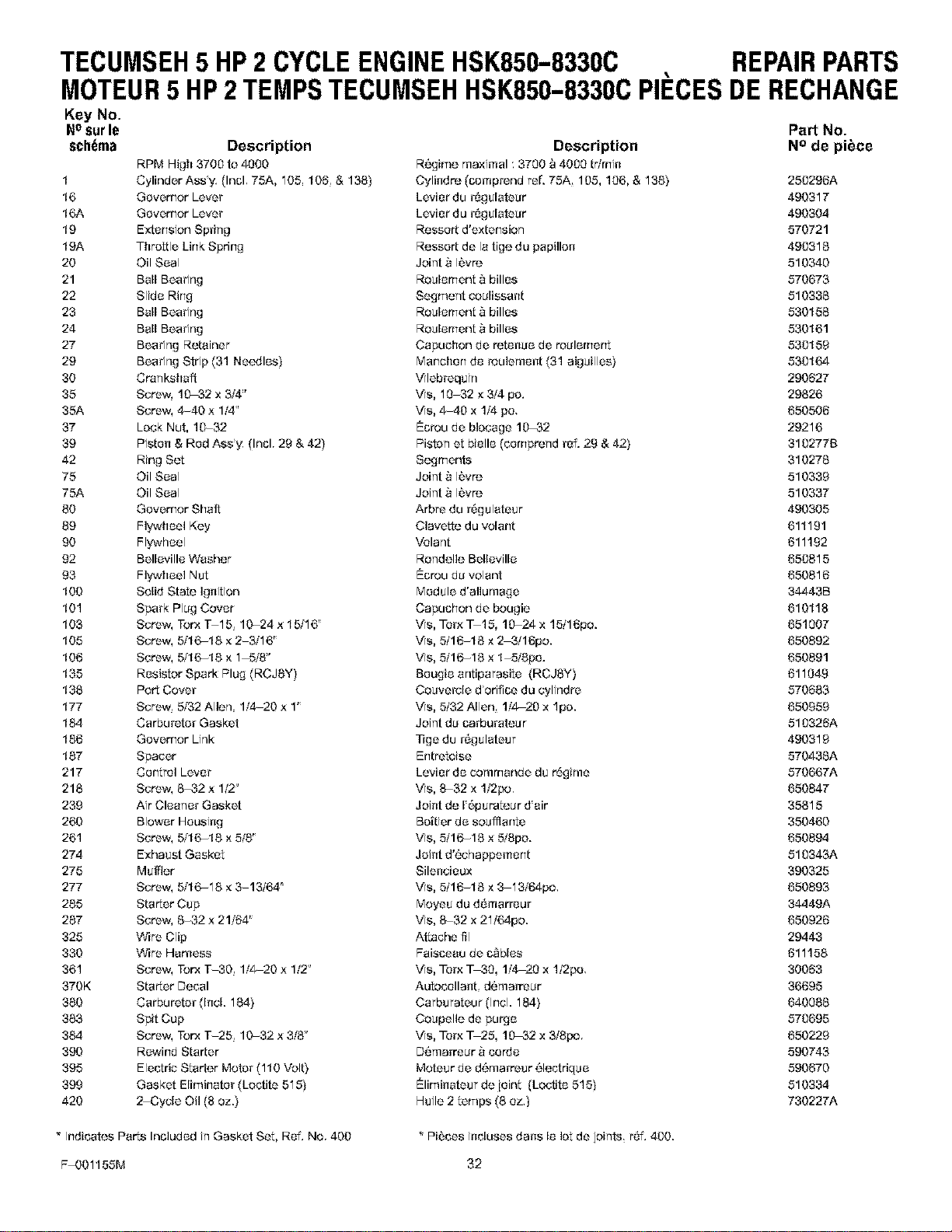
TECUMSEH5 HP2 CYCLEENGINEHSK850-83300 REPAIRPARTS
MOTEUR5 HP2TEMPSTECUMSEHHSK850-8330CPII CESDERECHANGE
Key No.
NOsurle Part No.
schema Description Description N° de piece
RPM High 3700 to 4000 R_'girTle rl]aximal 3700 "_4000 tr/mi_t
Cylind er Ass'y, (Incl, 75A, 105, 106 & 138) Cylindre (comprend ref. 76A 106, 106, & 138)
Governor Lever Levier du r_gulutaur
Governor Lever Levier du r_gulutaur
Extension Spring Ressort d'extension
Throttle Link Spring Ressert de la tige du papillen
Oil Seal Joint _ I_vre
Bull Bearing Roulement _ billes
Slide Rirl_ Segment aoulissant
Bull Bearing Roulement _ billes
Bull Bearing Roulement _ billes
Bearing Retainer Capuchon de rete_tue de roulement
Bearirlg Stdp (31 Needles) Marlcherl de t_ulemef_t (31 aiguilles)
Crankshaft Wlebrequin
Screw. 10_32 x 3/4" Ws, 10-32 x 3/4 po.
Screw, 4-40 x 1f4" Ws, 4-40 x 1/4 pc.
Lock Nut, 1_32 Eurou de blocuge 10_32
Pisten & Red Assy, (Incl, 29 & 42) Piston et bielle (cemprerld ref. 28 & 42)
Ring Set Segments
Oil Seal Joint _ I_vre
Oil Seal Joint _ I_vre
Governor Shaft Arbre du l_gulutaur
Flywheel Key Clavette du volant
Flywheel Volant
Belleville Washer Rondelle Belleville
Flywheel Nut Eurou du volant
Solid State Ig{tition Module d'allume_e
Spark Plug Cover Capuchon de bougie
Screw, Torx T-15 10-24 x 15/'16" Ws, Terx _15, 1_24 x 15/16po.
Screw, 5/'16-18 × 2-3/'16" Ws, 5/16-16 × 2_3/16po.
Screw, 5/'16-18 x 1_5/8" Ws, 5/16-16 x 1-5/8pe.
Resistor Spark Plug (RCJSY) Beugie antiparasite {RCJ6Y)
Port Cover Couvel_le d'orifice du cylindre
Screw, 5/32 Allen, 1/420 x 1" Ws, 5/32 Allen 1/'4-20 x lpo.
Carburetor Gasket Joint du carbureteur
Governor Link Tige du r6gulutaur
Spacer Entretoise
Control Lever Levier de communde du r6gime
Screw, 6-32 x 1/2" Ws, 6-32 x 1/2po.
Air Cleaner Gasket Joint de 1'6pureteur d'uir
Blower Housing Battier de soufflante
Screw, 5/'16-18 × 5/8" Ws, 5/16-16 x 518po.
Exhaust Gasket Joint d'_,chappement
Muffler Silencieux
Screw, 5/'16-18 × _13/64 _ Ws, 5/16-16 × 3-13f64p0,
Starter Cup Moyeu du d_marl_ur
Screw, 6-32 x 21/'64" Ws, 6-32 x 21/64po.
Wire Clip Attache fil
Wire Harness Feisceuu de a_bles
Screw, Torx T-30 1/420 x 1f2" Ws, Tar× T_30, 1/'4-20 x 1/2po,
Starter Decal Autocolla{tt, d{_marreur
Carburetor (Incl. 184) Carburateur (Irlcl. 184}
Spit Cup Coupelle de purge
Screw, Torx T-25 10-32 x 3/'6" Ws, Tar× T 25, 10_32 x 3/8p0.
Rewind Star_er D{_marreur _ cerde
Electric Starter Motor (110 Volt} Moteur de d6marreur 61ectrigue
Gasket Elimirlater (Loctita 516} Elimklutaur de ieint (Loctite 515)
2-Cycle Oil (8 oz.) Huile 2 tempe (8 ez.)
1 250296A
16 490317
16A 490304
19 570721
19A 490316
20 510340
21 570673
22 510336
23 530156
24 530161
27 630159
29 630164
30 290627
35 29826
35A 650506
37 29216
39 310277B
42 310276
75 510339
75A 510337
80 490305
89 611191
90 611192
92 650815
93 650816
100 34443B
101 610118
103 651007
105 650892
106 650891
135 611049
136 570683
177 650959
184 510326A
186 490319
187 570436A
217 570667A
216 650847
239 35615
260 350460
261 650894
274 510343A
275 390325
277 650893
285 34449A
287 650926
325 29443
330 611158
361 30063
370K 36695
380 640086
383 570695
384 650229
390 590743
395 590670
399 510334
420 730227A
* Indicates Parts Included it1 Gasket Set, Ref. No. 400 * Pi6ces incluses dens le lot de joirffs r6f. 400.
F-001156M 32
TECUMSEH5 HP2 CYCLEENGINEHSK850-83300 REPAIRPARTS
MOTEUR5 HP2TEMPSTECUMSEHHSK850-8330CPII_CESDERECHANGE
Key No.
Nosurle
schema
O
1
6
7
10
14
15
16
25
26
27
28
29
30
31
32
33
36
37
40
44
48
60
F-001156M
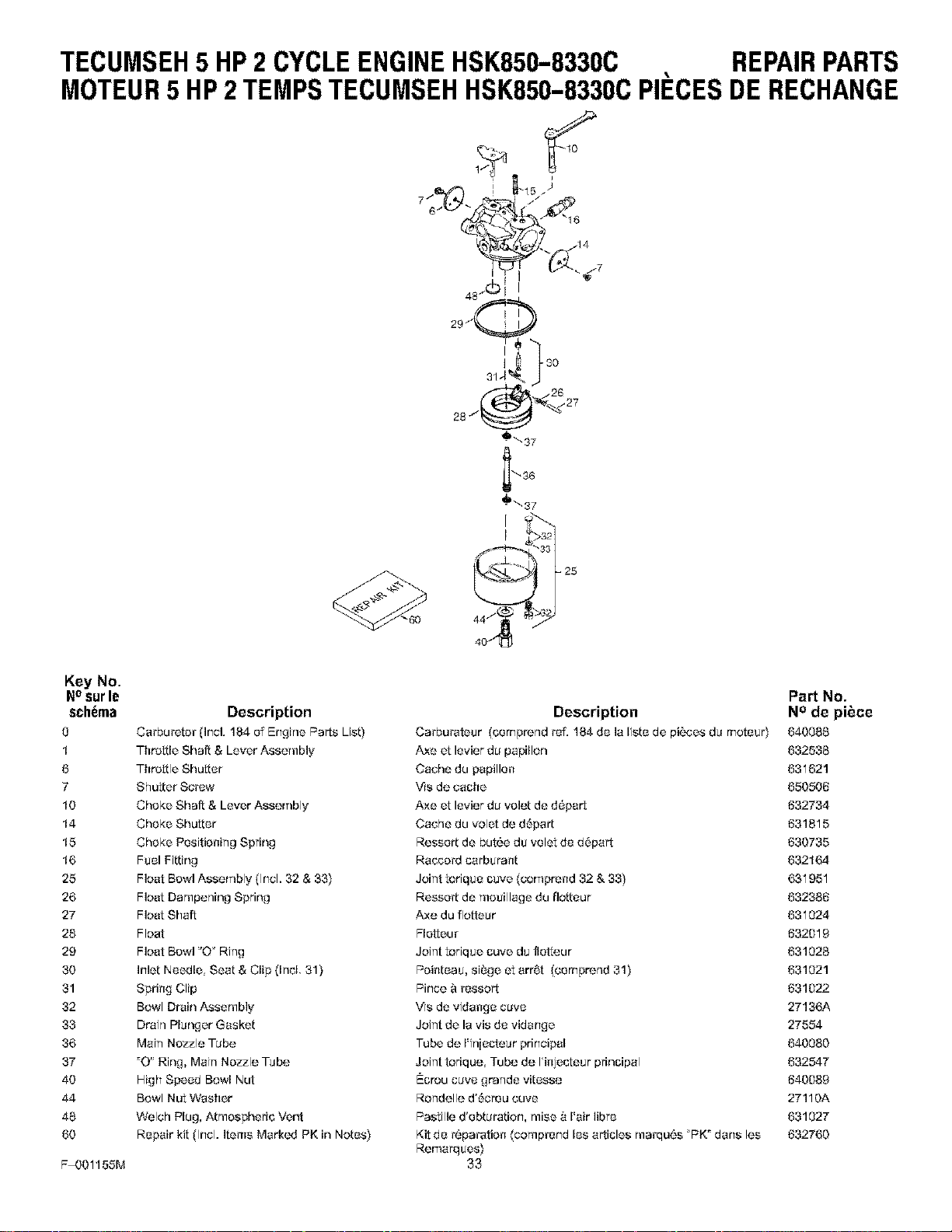
Description
Ca++bu_ete++(Irlc]. 184 of Brlghe Parts Us{)
Throttle Shaft & Lever Assembly
Throttle Shutter
Shutter Scl'ow
Choke Shaft & Lever Assembly
Choke Shutter
Choke Positioning Spring
FuelFitting
Flea{ Bowl Assembly (Incl. 32 & 33)
Float Dampening Spring
Float Shaft
Float
Flea{ Bowl "O+Ring
Inlet Needle, Seat & Clip(Irlcl. 31)
Spring Clip
Bowl Drain Assembly
Drain Plunger Gasket
Main Nozzle Tube
_O" Ring, Main Nozzle Tube
High Speed Bowl Nut
Bowl Nut Washer
Welch Plug, Atmospheric Vent
Repair kit (Incl. Items Marked PK in Notes)
Part No.
Description N ° de piece
Cat+burateur (cornprerld _ef. 184 de la Iiste de piL_es du rnotear) 640086
Axe et levier du papillon 632536
Cache du papillon 631621
",ASde cache 650506
Axe et levier du vole{ de d6part 632734
Cache du vole{ de d_part 631815
Ressort de but6e da velet de d6part 630735
RaccoJ'd carbarant 632164
Joint toriqae cave {corTiprend 32 & 33) 631951
Ressott de moaillage du flotteur 632386
Axe du rio{tear 631024
Fletteu_" 632019
Joint toriqae cuve da fie{tour 631026
Pointeaa, si_ge et arr6t (cernprerld 31) 631021
Pince "_l'ossor t 631022
We de vidange cave 27136A
Joint de la vis de vidange 27554
Tube de Iqr!iecteur principal 640080
Joint torique, Tube de I+injecteur principal 632547
Ecrou cuve grarlde vitesse 640089
Rondelle d'_creu cave 27110A
Pastille d'obturation, raise _ I'air libre 631027
Kit de r-_paration (comp_'orld los articles mal'qu{_s F_K_darls los 632760
RerTlarqaes)
33
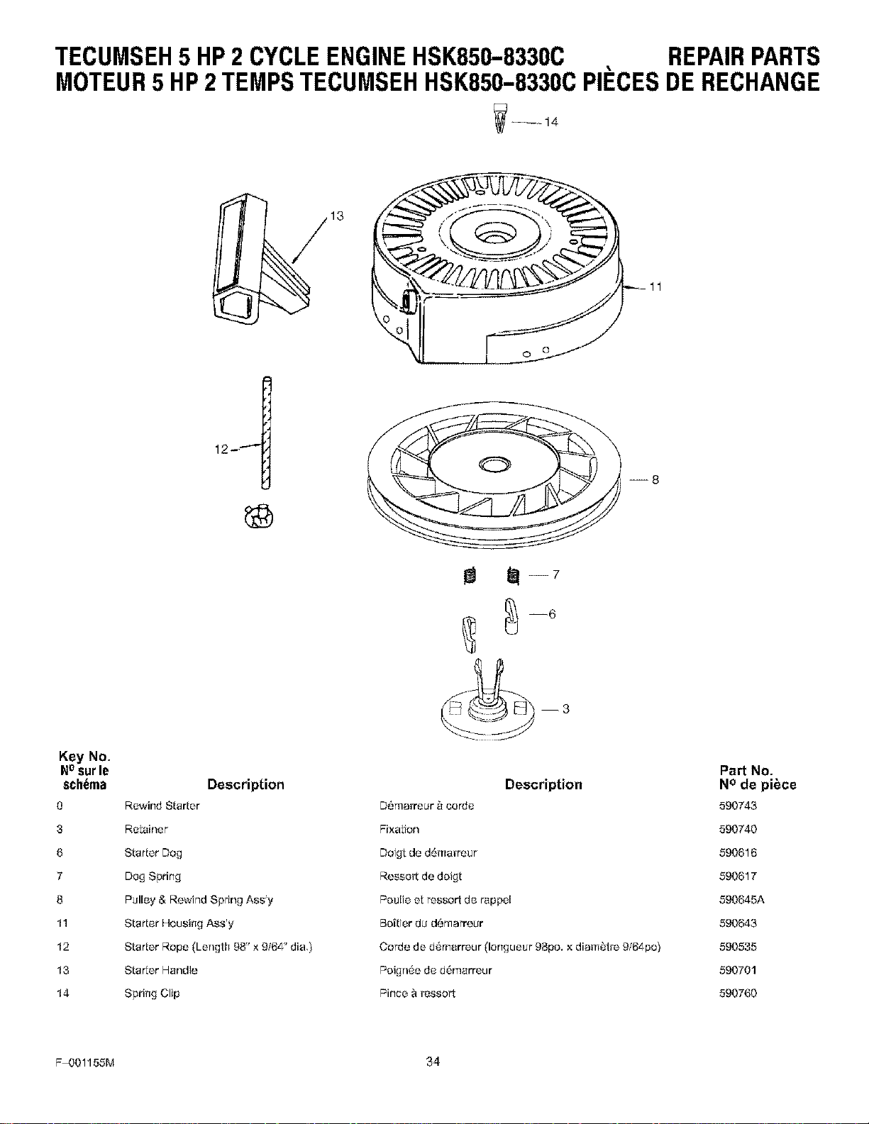
TECUMSEH5 HP2 CYCLEENGINEHSK850-83300 REPAIRPARTS
MOTEUR5 HP2TEMPSTECUMSEHHSK850-8330CPII_CESDERECHANGE
3 11
--8
Key No.
Nosurle
schema Description
O Rewind Starter
3 Retainer
6 Starter Dog
7 Dog Spring
8 Pulley & Rewind Spring Ass'y
11 Starter Housing Ass'y
12 Starter Rope (Length 98" × 9/64" dia,)
13 Star_er Handle
14 Spring Clip
_--7
Description
D{_rnarreur _ _orde
Fi×al:ion
Doigt de d6marreur
Resse_t de doigt
Pe_lie e_ressort de rappel
Be[tier du d{_marreur
Corde de d_marreur (lerlgueur 98pc. × diamLztJ_9/64po)
Peigr16e de d6marreur
Pince & _ssort
Part No.
N ° de piece
590743
590740
590616
590617
590645A
590643
590535
590701
590760
F-001155M 34

NOTES
F-OO1155M 35
SWARS
owner's
manual
Model
C950-52935-1
SINGLE STAGE
SNOW BLOWER
CRRFT MRN
SERVICE
is at
YOUR
SERVICE
Serial No.
Model and Sedal Number may be
found on the number plate on the
rear of the Snow blower,
You should record both Model and
Serial Number and keep in a safe
place for future reference.
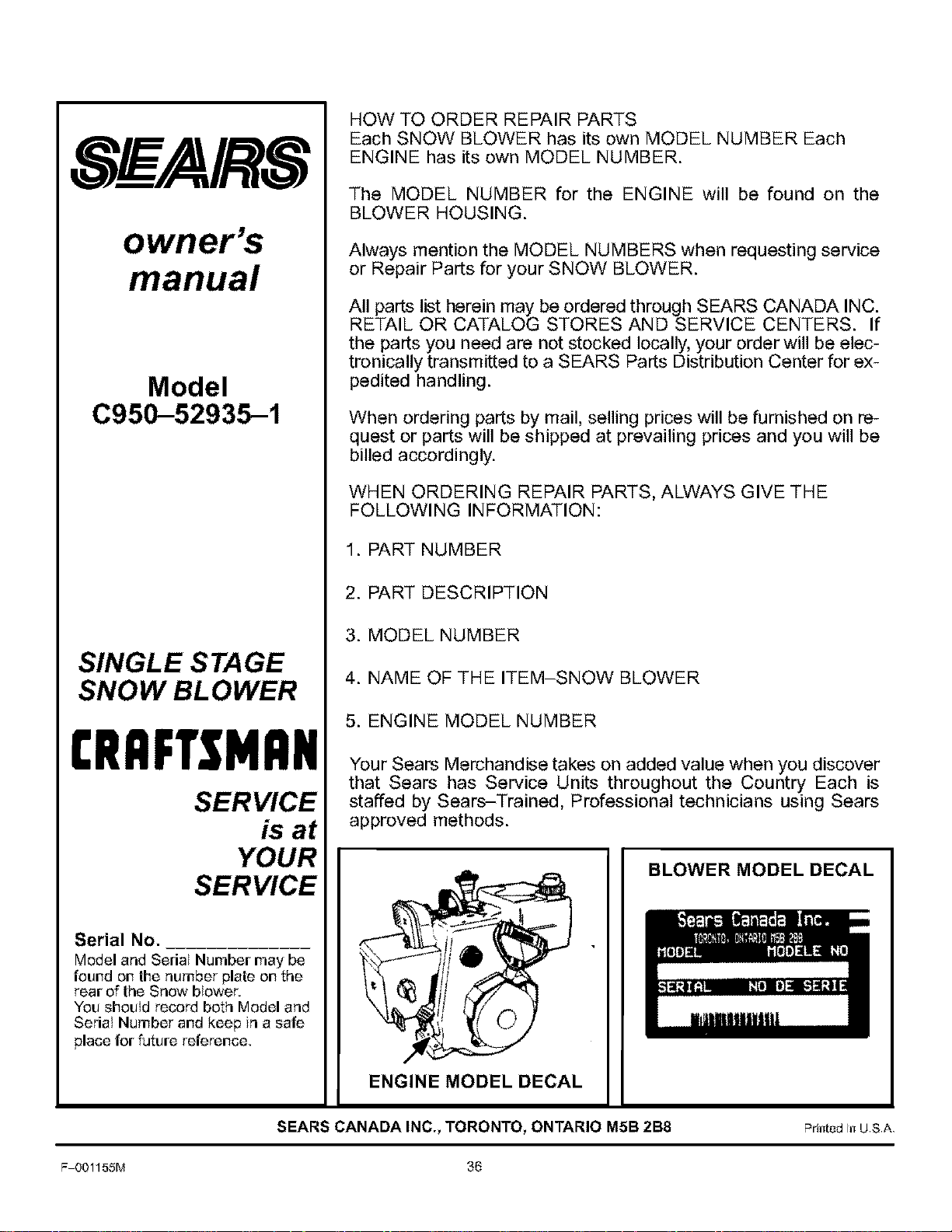
HOW TO ORDER REPAIR PARTS
Each SNOW BLOWER has its own MODEL NUMBER Each
ENGINE has its own MODEL NUMBER.
The MODEL NUMBER for the ENGINE will be found on the
BLOWER HOUSING.
Always mention the MODEL NUMBERS when requesting service
or Repair Parts for your SNOW BLOWER.
All parts list herein may be ordered through SEARS CANADA INC.
RETAIL OR CATALOG STORES AND SERVICE CENTERS. If
the parts you need are not stocked locally, your order will be elec-
tronically transmitted to a SEARS Parts Distribution Center for ex-
pedited handling.
When ordering parts by mail, selling prices will be furnished on re-
quest or parts will be shipped at prevailing prices and you will be
billed accordingly.
WHEN ORDERING REPAIR PARTS, ALWAYS GIVE THE
FOLLOWING INFORMATION:
1. PART NUMBER
2. PART DESCRIPTION
3. MODEL NUMBER
4. NAME OF THE ITEM-SNOW BLOWER
5. ENGINE MODEL NUMBER
Your Sears Merchandise takes on added value when you discover
that Sears has Service Units throughout the Country Each is
staffed by Sears-Trained, Professional technicians using Sears
approved methods.
BLOWER MODEL DECAL
ENGINE MODEL DECAL
SEARS CANADA INC., TORONTO, ONTARIO M5B 2B8
Pdnted in U,S,A,
F-001155M 36


