Loading ...
Loading ...
Loading ...
LY
CAUTION: tF YOU ARE REMOVING
SNOW FROM ANY ROCKY OR UNEVEN
SURFACES, RAISE THE FRONT OF THE
SNOW THROWER BY MOVING THE
SKIDS DOWN. THIS WILL HELP TO PREVENT
ROCKS AND OTHER DEBRIS FROM BEING
PI_.KED UP AND THROWN BY THE AUGER.
................... H I ,,lNI I
TO iNSTALL UPPER HANDLE AND
CRANK ASSEMBLY
® 0n the right side of the handle, install and secure the
_ollowing parts (found in parts bag) in the lower
l_andle hole as shown in figure 4A:
_1- 3/8" x 2" bolt
,1 - 3/8" flatwasher & 3/8" Iockwasher
f
;1 - 3/8" nut
® Remove the 3/8" nylon iocknut and flatwasher from
hneeye bolt assembly (on the chute crank assembly)
d adjust the two remaining 3/8" jam nuts, the flat-
washer and the adapter on the eye bolt about half
vyay up the thread._
o Install eye bolt through the lower hole on the left hand
side of the handle,
o Install the 3/8" flatwasher and 3/8" nylon Iocknut
!posely on the eye bolt, as shown.
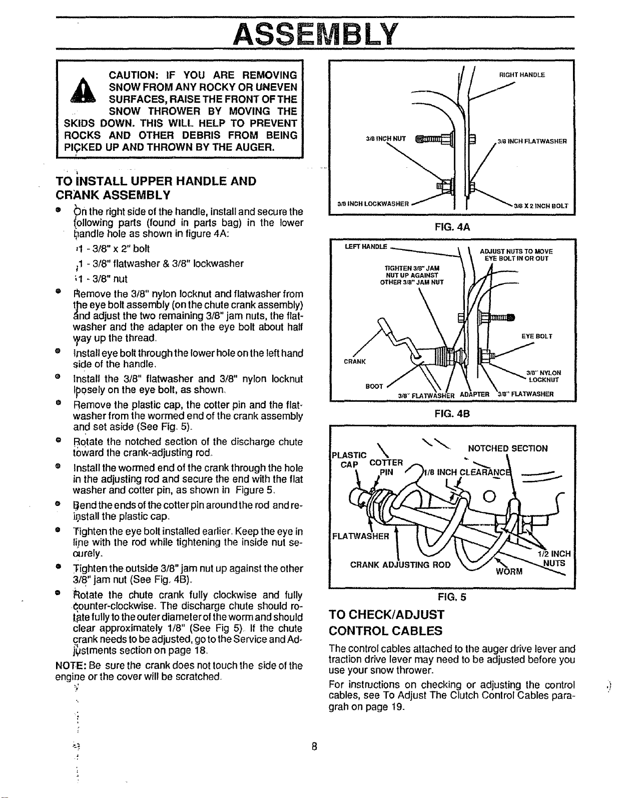
® Remove the plastic cap, the cotter pin and the flat-
washer from the wormed end of the crank assembly
and set aside (See Fig..5)..
® Rotate the notched section of the discharge chute
toward the crank-adjusting rod.
® Install the wormed end of the crank through the hole
in the adjusting rod and secure the end with the flat
washer and cotter pin, as shown in Figure 5.
e Bend the ends of the cotter pin around the rod and re-
i0sta!l the plastic cap.
® Tighten the eye bolt installed earlier. Keep the eye in
lipe with the rod while tightening the inside nut se-
o_Jrelyo
• Tighten the outside 3/8" jam nut up against the other
3/8" jam nut (See Fig. 4B).
o l_otate the chute crank fully clockwise and fully
€,ounter-clockwise. The discharge chute should ro-
Latefully tothe outer diamet erof the worm and should
clear approximately 1/8" (See Fig 5).. If the chute
crank needs to be adjusted, go to the Service and Ad-
justments section on page 18..
NOTE: Be sure the crank does not touch the side of the
engir]e or the cover will be scratched..
RIGHT HANDLE
3/8 |NCH FLATWASHER
3/8 X 2 INCH BOLT
EYE BOLT
FIG. 5
TO CHECK/ADJUST
CONTROL CABLES
The control cables attached to the auger drive lever and
traction drive lever may need to be adjusted before you
use your snow thrower.
For instructions on checking or adjusting the control
cables, see To Adjust The Clutch Control Cables para-
grah on page 19.
Loading ...
Loading ...
Loading ...