
Operator's Manual
ICRAFTSMnN°J
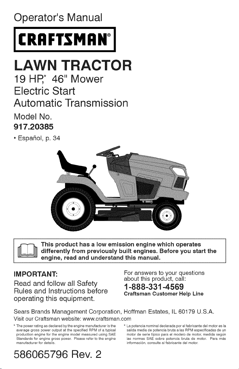
LAW TRACTOR
19 HR* 46" Mower
Electric Start
Automatic Transmission
Model No.
917.20385
, EspaSol, p. 34
_] his product has a low emission engine which operates
differently from previously built engines. Before you start the
engine, read and understand this manual.
iMPORTANT:
Read and follow all Safety
Rules and instructions before
operating this equipment.
For answers to your questions
about this product, call:
1-888-331-4569
Craftsman Customer Help Line
Sears Brands Management Corporation, Hoffman Estates, IL 60179 U.S.A.
Visit our Craftsman website: www.craftsman.com
* The power rating as declared by the engine manufacturer is the
average gross power output at the specified RPM of a typical
production engine for the engine model measured using SAE
Standards for engine gross power. Please refer to the engine
manufacturer for detaits.
* La potencia nominal declarada per el fabricante del motor es la
salida media de potencia bruta a las RPM especificadas de un
motor de serie tipico para el modelo de motor, medida segt_n
las normas SAE sobre potencia bruta de moton Para mas
informaci6n, consulte al fabricante del motor.
586065796 Rev. 2

Warranty .................................................. 2
Safety Rules ............................................ 3
Product Specifications ............................. 6
Assembty/Pre-Operation ......................... 7
Operation ................................................. 9
Maintenance Schedule .......................... 16
Maintenance .......................................... 16
Service and Adjustments ....................... 21
Storage .................................................. 28
Troubleshooting ..................................... 29
Sears Service ......................... Back Cover
Craftsman Riding Equipment Warranty
CRAFTSMAN FULL WARRANTY
FOR TWO YEARS from the date of purchase, all non-expendable parts of this riding equipment are
warranted against any defects in material or workmanship. A defective non-expendable part will
receive free in-home repair or replacement if repair is impossible.
FOR FIVE YEARS from the date of purchase, the frame and front axle of this riding equipment are
warranted against any defects in material or workmanship. A defective frame or front axle will receive
free in-home repair or replacement if repair is impossible.
FOR 90 DAYS from the date of purchase, the battery (an expendable part) of this riding equipment
is warranted against any defects in material or workmanship (our testing proves that it will not hold a
charge). A defective battery will receive free in-home replacement.
ADDITIONAL LIFETIME LIMITED WARRANTY on CAST IRON FRONT AXLE (if equipped)
FOR AS LONG AS IT IS USED by the original owner after the fifth year from the date of purchase, the
cast iron front axle (if equipped) of this riding equipment is warranted against any defects in material or
workmanship. With proof of purchase, a defective cast front axle will receive free in-home replacement.
WARRANTY SERVICE
For warranty coverage details to obtain free repair or replacement, call 1-800-659-5917 or visit the
web site: www.craftsman.com
In all cases above, if part repair or replacement is impossible, the riding equipment will be replaced
free of charge with the same or an equivalent model.
All of the above warranty coverage is void if this riding equipment is ever used while providing
commercial services or if rented to another person.
This warranty covers ONLY defects in material and workmanship. Warranty coverage does NOT
include:
• Expendable parts (except battery) that can wear out from normal use within the warranty period,
including but not limited to blades, spark plugs, air cleaners, belts, and oil filters.
• Standard maintenance servicing, oil changes, or tune-ups.
• Tire replacement or repair caused by punctures from outside objects, such as nails, thorns,
stumps, or glass.
• Tire or wheel replacement or repair resulting from normal wear, accident, or improper operation or
maintenance.
• Repairs necessary because of operator abuse, including but not limited to damage caused by
towing objects beyond the capability of the riding equipment, impacting objects that bend the
frame, axle assembly or crankshaft, or over-speeding the engine.
• Repairs necessary because of operator negligence, including but not limited to, electrical and
mechanical damage caused by improper storage, failure to use the proper grade and amount
of engine oil, failure to keep the deck clear of flammable debris, or failure to maintain the riding
equipment according to the instructions contained in the operator's manual.
• Engine (fuel system) cleaning or repairs caused by fuel determined to be contaminated or oxidized
(stale). In general, fuel should be used within 30 days of its purchase date.
• Normal deterioration and wear of the exterior finishes, or product label replacement.
This warranty gives you specific legal rights, and you may also have other rights which vary from
state to state.
Sears Brands Management Corporation, Noffman Estates, IL 60179
2
_I_,DANGER: This cutting machine is capable of amputating hands and feet and
throwing objects. Failure to observe the following safety instructions could result
in serious injury or death.
_WARNING: In order to prevent acciden-
tal starting when setting up, transporting,
adjusting or making repairs, always discon-
nect spark plug wire and place wire where
it cannot contact spark plug.
_,WARNING: Do not coast down a hill in
neutral, you may lose control of the tractor.
_,WARNING: Tow only the attachments
that are recommended by and comply with
specifications of the manufacturer of your
tractor. Use common sense when towing.
Operate only at the lowest possible speed
when on a slope. Too heavy of a load, while
on a slope, is dangerous. Tires can lose
traction with the ground and cause you to
lose control of your tractor.
_WARNING: Engine exhaust, some of
its constituents, and certain vehicle compo-
nents contain or emit chemicals known to
the State of California to cause cancer and
birth defects or other reproductive harm.
_,WAR NING: Battery posts, terminals and
related accessories contain lead and lead
compounds, chemicals known to the State of
California to cause cancer and birth defects
or other reproductive harm. Wash hands
after handling,
I. GENERAL OPERATION
• Read, understand, and follow all instruc-
tions on the machine and in the manual
before starting.
• Do not put hands or feet near rotating
parts or under the machine. Keep clear
of the discharge opening at all times.
• Only allow responsible adults, who are
familiar with the instructions, to operate
the machine.
• Clear the area of objects such as rocks,
toys, wire, etc., which could be picked
up and thrown by the blades.
• Be sure the area is clear of bystanders
before operating. Stop machine if anyone
enters the area.
• Never carry passengers.
• Do not mow in reverse unless absolutely
necessary. Always took down and behind
before and while backing.
Never direct discharged material toward
anyone. Avoid discharging material
against a wall or obstruction. Material
may ricochet back toward the operator.
Stop the blades when crossing gravel
surfaces.
Do not operate machine without the en-
tire grass catcher, discharge chute, or
other safety devices in place and working.
• Slow down before turning.
Never leave a running machine unat-
tended. Always turn off blades, set
parking brake, stop engine, and remove
keys before dismounting.
Disengage blades when not mowing.
Shut off engine and wait for all parts to
come to a complete stop before cleaning
the machine, removingthe grass catcher,
or unclogging the discharge chute.
• Operate machine ontyin daytightorgood
artificial light.
Do not operate the machine while under
the influence of alcohol or drugs.
• Watch for traffic when operating near or
crossing roadways.
• Use extra care when loading or unloading
the machine into a trailer or truck.
Always wear eye protection when operat-
ing machine.
Use ear protectors to avoid damage to
hearing.
Data indicates that operators, age 60
years and above, are involved in a large
percentage of riding mower-related inju-
ries. These operators should evaluate
their ability to operate the riding mower
safely enough to protect themselves and
others from serious injury.
Followthe manufacturer's recommenda-
tion for wheel weights or counterweights.
Keep machine free of grass, leaves or
other debris build-up which can touch hot
exhaust / engine parts and burn. Do not
allow the mower to plow leaves or other
debris which can cause build-up to oc-
cur. Clean any oil or fuel spillage before
operating or storing the machine. Allow
machine to cool before storage.
II.SLOPEOPERATION
Slopesareamajorfactorrelatedtolossof
controlandtip-overaccidents,whichcan
resultinsevereinjuryordeath.Operation
onallslopesrequiresextra caution. If you
cannot back up the slope or if you feet uneasy
on it, do not mow it.
* Mow up and down slopes, not across.
* Watch for holes, ruts, bumps, rocks, or
other hidden objects. Uneven terrain
could overturn the machine. Tall grass
can hide obstacles.
* Choose a low ground speed so that you
will not have to stop or shift while on the
slope.
* Do not mow on wet grass. Tires may lose
traction.
Always keep the machine in gear when
going down slopes. Do not shiftto neutral
and coast downhill.
* Avoid starting, stopping, or turning on a
slope. Ifthetirestosetraction, disengage
the blades and proceed slowly straight
down the slope.
* Keep all movement on the slopes stow
and gradual. Do not make sudden
changes in speed or direction, which
could cause the machine to roll over.
* Use extra care while operating machine
with grass catchers or other attachments;
they can affect the stability of the ma-
chine. Do no use on steep slopes.
* Do not try to stabilize the machine by
putting your foot on the ground.
* Do not mow near drop-offs, ditches,
or embankments. The machine could
suddenly roll over if a wheel is over the
edge or if the edge caves in.
Ill. CHILDREN
_/IWARNING: CHILDREN CAN BE INJURED
BY THIS EQUIPMENT The American Acade-
my of Pediatrics recommends that children
be a minimum of 12 year of age before op-
erating a pedestrian controlled lawn mower
and a minimum of 16 years of age before
operating a riding lawn mower.
Tragic accidents can occur if the operator
is not alert to the presence of children.
Children are often attracted to the machine
and the mowing activity. Never assume
that children will remain where you last
saw them.
* Keep children out of the mowing area
and in the watchful care of a responsible
adult other than the operator.
* Be alert and turn machine off if a child
enters the area.
* Before and while backing, look behind
and down for small children.
* Never carry children, even with the btades
shutoff. They may fall offand be seriously
injured or interfere with safe machine
operation. Children who have been given
rides in the past may suddenly appear in
the mowing area for another ride and be
run over or backed over by the machine.
* Never allow children to operate the ma-
chine.
* Use extra care when approaching blind
corners, shrubs, trees, or other objects
that may block your view of a child.
IV. TOWING
* Tow only with a machine that has a hitch
designed for towing. Do not attach towed
equipment except at the hitch point.
* Fotlowthemanufacturer'srecommenda-
tion for weight timits for towed equipment
and towing on slopes.
. Never allow children or others in or on
towed equipment.
* On stopes, theweightofthetowed equip-
ment may cause loss of traction and toss
of control.
* Travel slowly and allow extra distance to
stop.
V. SERVICE
SAFE HANDLING OF GASOLINE
To avoid personal injury or property dam-
age, use extreme care in handling gasoline.
Gasoline is extremely flammable and the
vapors are explosive.
. Extinguish all cigarettes, cigars, pipes,
and other sources of ignition.
. Use only approved gasoline container.
. Never remove gas cap or add fuel with
the engine running. Allow engine to cool
before refueling.
. Never fuel the machine indoors.
. Neverstorethemachineorfuelcontainer
where there is an open flame, spark, or
pilot light such as on a water heater or
other appliances.
Never fill containers inside a vehicle or
on a truck or trailer bed with plastic liner.
Always place containers on the ground
away from your vehicle when filling.
4
• Removegas-poweredequipmentfrom
thetruckortrailerandrefuelit onthe
ground.Ifthisisnotpossible,thenrefuel
suchequipmentwithaportablecontainer,
ratherthanfroma gasolinedispenser
nozzle.
Keepthenozzleincontactwiththerim
ofthefueltankorcontaineropeningat
alltimesuntilfuelingiscomplete.Donot
useanozzlelock-opendevice.
Iffuelisspilledonclothing,changecloth-
ingimmediately.
Neveroverfillfueltank.Replacegascap
andtightensecurely.
GENERALSERVICE
• Neveroperatemachineinaclosedarea.
Keepallnutsandboltstighttobesurethe
equipmentisinsafeworkingcondition.
Nevertamperwithsafetydevices.Check
theirproperoperationregularly.
Keepmachinefreeofgrass,leaves,or
otherdebrisbuild-up.Cleanoilorfuel
spillageandremoveanyfuel-soakedde-
bris.Allowmachinetocootbeforestoring.
Ifyoustrikea foreignobject,stopand
inspectthemachine.Repair,ifnecessary,
beforerestarting.
Nevermakeanyadjustmentsorrepairs
withtheenginerunning.
Checkgrasscatchercomponentsandthe
dischargechutefrequentlyandreplace
withmanufacturer'srecommendedparts,
whennecessary.
Mowerbladesaresharp.Wraptheblade
orweargloves,anduseextracaution
whenservicingthem.
• Checkbrakeoperationfrequentty.Adjust
andserviceasrequired.
Maintainorreplacesafetyandinstruction
labels,asnecessary.
Besuretheareaisclearofbystanders
beforeoperating.Stopmachineifanyone
entersthearea.
• Nevercarrypassengers.
Donotmowinreverseunlessabsolutely
necessary.Alwaystookdownandbehind
beforeandwhilebacking.
Nevercarrychildren,evenwiththe
bladesshutoff.Theymayfalloffand
beseriouslyinjuredorinterferewithsafe
machineoperation.Childrenwhohave
beengivenridesinthepastmaysuddenly
appearinthemowingareaforanother
rideandberunoverorbackedoverby
themachine.
Keepchildrenoutofthemowingarea
andinthewatchfulcareofaresponsible
adultotherthantheoperator.
• Bealertandturnmachineoffifa child
entersthearea.
• Beforeandwhilebacking,tookbehind
anddownforsmallchildren.
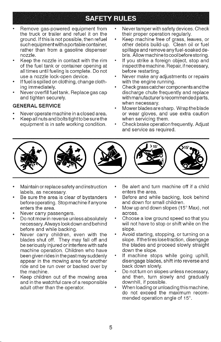
Mowupanddownslopes(15°Max),not
across.
Choosealowgroundspeedsothatyou
willnothavetostoporshiftwhileonthe
slope.
Avoidstarting,stopping,orturningona
slope.Ifthetirestosetraction,disengage
thebladesandproceedslowlystraight
downtheslope.
• If machinestopswhilegoinguphill,
disengageblades,shiftintoreverseand
backdownslowly.
Donotturnonslopesunlessnecessary,
andthen,turnslowlyandgradually
downhill,ifpossible.
• WhenIoadingorunloadingthismachine,
do notexceedthemaximumrecom-
mendedoperationangleof15°.

PRODUCTSPECIFiCATiONS
Gasoline Capacity 2.5 Gallons / 9,46 L
and type: Regular Unleaded *
Oil Type: SAE 10W30 (above 32°F/0°C
(API: SG-SL) SAE 5W30 (below 32°F/0°C
Oil Capacity: W/Filter: 51 Oz. / 1,5 L
W/out Filter: 35 Oz. / 1,05 L
Spark Plug: Champion 24 132 03
(Gap: .030"/0,76 mm)
Charging System: 13 Amps @ 3600 RPM
Battery: Amp/Hr: 28
Min. CCA: 230
Case size: U1R
Blade Bolt Torque: 45-55 Ft. Lbs./62-75 Nm
*_lLGasoline containing up to 10% ethanol (El0) is
acceptable for use in this machine. The use of
any gasoline exceeding 10% ethanol (El0) will
void the product warranty.
CONGRATULATIONS on your purchase of
a new tractor. It has been designed, engi-
neered and manufactured to give you the best
possible dependability and performance.
Should you experience any problem you can-
not easily remedy, please contact a Sears or
other qualified service center. We have com-
petent, well-trained representatives and the
proper tools to service or repair this tractor.
Please read and retain this manual. The
instructions will enable you to assemble
and maintain your tractor properly. Always
observe the "SAFETY RULES".
CUSTOMER RESPONSIBILiTiES
Read and observe the safety rules.
* Follow a regular schedule in maintaining,
caring for and using your tractor.
* Follow instructions under "Maintenance"
and "Storage" sections of this manual.
* Wear proper Personal Protective Equip-
ment (PPE) while operating this machine,
including (at a minimum) sturdy footwear,
eye protection, and hearing protection.
Do not mow in shorts and/or open toed
footwear.
* Always tetsomeone knowyou are outside
mowing.
_,WARNING: This tractor is equipped with
an internal combustion engine and should
not be used on or near any unimproved
forest-covered, brush-covered or grass-
covered land unless the engine's exhaust
system is equipped with a spark arrester
meeting applicable local or state laws (if
any). If a spark arrester is used, it should
be maintained in effective working order by
the operator.
In the state of California the above is required
by taw (Section 4442 of the California Public
Resources Code). Other states may have
similar laws. Federal laws apply on federal
lands. A spark arrester for the muffler is
available through your nearest Sears service
center (See REPAIR PARTS manual).
REPAIR PROTECTION AGREEMENTS
Congratulations on making a smart pur-
chase. Your new Craftsman@ product is
designed and manufactured for years of
dependable operation. But like all products,
it may require repair from time to time. That's
when having a Repair Protection Agreement
can save you money and aggravation.
Purchase a Repair Protection Agreement
now and protect yourself from unexpected
hassle and expense.
Here's what's included in the Agreement:
Expert service by our 12,000 professional
repair specialists.
U ntimited service and no charge for parts
and labor on all covered repairs.
Product replacement if your covered
product can't be fixed.
Discount of 25% from regular price of
service and service-related parts not
covered bythe agreement; also, 25% off
regular price of preventive maintenance
check.
Fast help by phone - phone support
from a Sears representative on products
requiring in-home repair, plus convenient
repair scheduling.
Once you purchase the Agreement, a simple
phone call is all that it takes for you to sched-
ule service. You can call anytime day or night,
or schedule a service appointment online.
Sears has over 12,000 professional repair
specialists, who have access to over 4.5
million quality parts and accessories. That's
the kind of professionalism you can count on
to help prolong the life of your new purchase
for years to come. Purchase your Repair
Protection Agreement today!
Some limitations and exclusions apply.
For prices and additional information call
1-800=827-6655,
SEARS INSTALLATION SERVICE
For Sears professional installation of home
appliances, garage door openers, water
heaters, and other major home items, inthe
U.S.A. call 1-800-4-MY-HOME@.
6
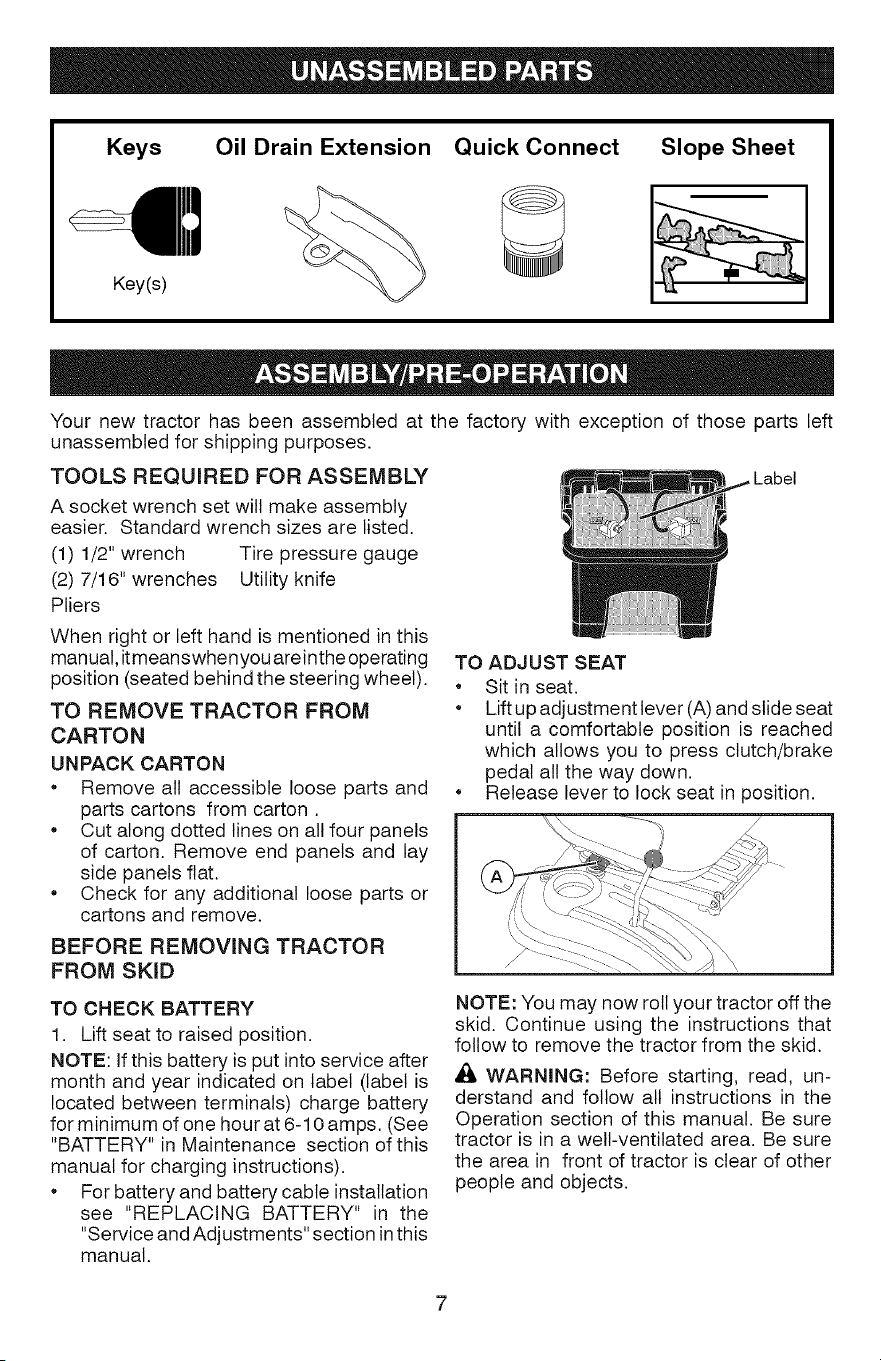
Keys Oil Drain Extension Slope Sheet
Key(s)
Quick Connect
Your new tractor has been assembled at the factory with exception of those parts left
unassembted for shipping purposes.
TOOLS REQUIRED FOR ASSEMBLY
A socket wrench set will make assembly
easier. Standard wrench sizes are listed.
(1) 1/2" wrench Tire pressure gauge
(2) 7/16" wrenches Utility knife
Pliers
When right or left hand is mentioned in this
manual, it meanswhen you areinthe operating
position (seated behind the steering wheel).
TO REMOVE TRACTOR FROM
CARTON
UNPACK CARTON
Remove all accessible loose parts and
parts cartons from carton.
Cut along dotted lines on all four panels
of carton. Remove end panels and lay
side panels flat.
Check for any additional loose parts or
cartons and remove.
BEFORE REMOVING TRACTOR
FROM SKID
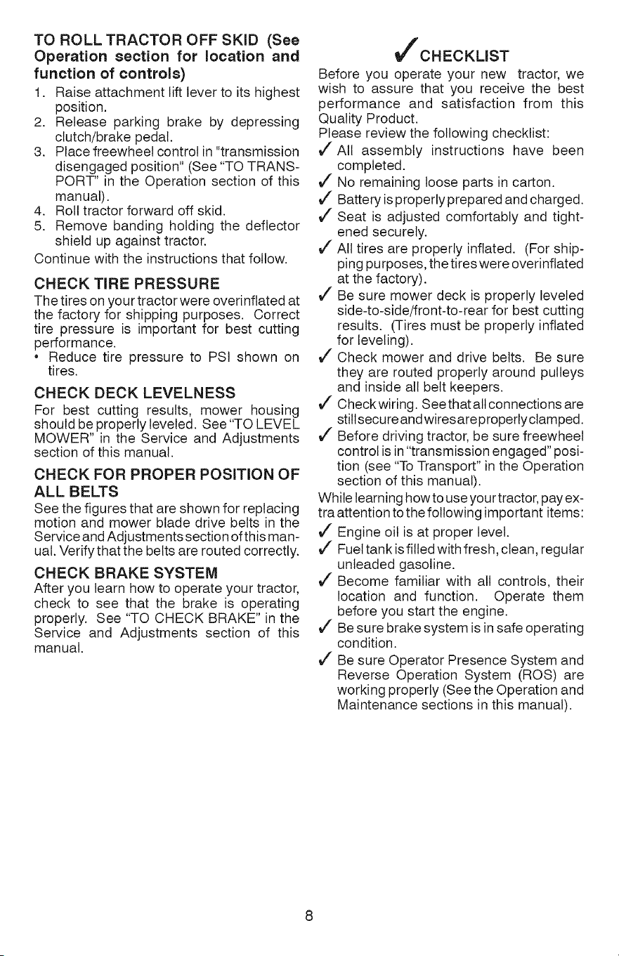
TO ADJUST SEAT
Sit in seat.
Lift up adjustment lever (A) and slide seat
until a comfortable position is reached
which allows you to press clutch/brake
pedal all the way down.
Release lever to lock seat in 3osition.
TO CHECK BATTERY
1. Lift seat to raised position.
NOTE: If this battery is put into service after
month and year indicated on label (label is
located between terminals) charge battery
for minimum of one hour at 6-10 amps. (See
"BATTERY" in Maintenance section of this
manual for charging instructions).
* For batteryand battery cable installation
see "REPLACING BATTERY" in the
"Service and Adjustments" section in this
manual.
NOTE: You may now roll your tractor off the
skid. Continue using the instructions that
follow to remove the tractor from the skid.
WARNING: Before starting, read, un-
derstand and follow all instructions in the
Operation section of this manual. Be sure
tractor is in a well-ventilated area. Be sure
the area in front of tractor is clear of other
people and objects.
TO ROLL TRACTOR OFF SKiD (See
Operation section for location and
function of controls)
1. Raise attachment lift lever to its highest
position.
2. Release parking brake by depressing
clutch/brake pedal.
3. Place freewheel control in "transmission
disengaged position" (See "TO TRANS-
PORT" in the Operation section of this
manual).
4. Roll tractor forward off skid.
5. Remove banding holding the deflector
shield up against tractor.
Continue with the instructions that follow.
CHECK TiRE PRESSURE
The tires on your tractor were overinftated at
the factory for shipping purposes. Correct
tire pressure is important for best cutting
performance.
Reduce tire pressure to PSI shown on
tires.
CHECK DECK LEVELNESS
For best cutting results, mower housing
should be properly leveled. See "TO LEVEL
MOWER" in the Service and Adjustments
section of this manual.
CHECK FOR PROPER POSiTiON OF
ALL BELTS
See the figures that are shown for replacing
motion and mower blade drive belts in the
Service and Adjustments section of this man-
ual. Verifythat the belts are routed correctly.
CHECK BRAKE SYSTEM
After you learn how to operate your tractor,
check to see that the brake is operating
properly. See "TO CHECK BRAKE" in the
Service and Adjustments section of this
manual.
VfCHECKLIST
Before you operate your new tractor, we
wish to assure that you receive the best
performance and satisfaction from this
Quality Product.
Please review the following checklist:
All assembly instructions have been
completed.
No remaining loose parts in carton.
_/ Battery is properly prepared and charged.
_/Seat is adjusted comfortably and tight-
ened securely.
_/All tires are properly inflated. (For ship-
ping purposes, the tires were overinftated
at the factory).
_/ Be sure mower deck is properly leveled
side-to-side/front-to-rear for best cutting
results. (Tires must be properly inflated
for leveling).
_/Check mower and drive belts. Be sure
they are routed properly around pulleys
and inside all belt keepers.
_/Check wiring. See that all connections are
still secure and wires are properly clamped.
_/Before driving tractor, be sure freewheel
control is in "transmission engaged" posi-
tion (see "To Transport" in the Operation
section of this manual).
While learning how to use your tractor, pay ex-
tra attention to the following important items:
_/Engine oil is at proper level.
_/Fuel tank is filled with fresh, clean, regular
unleaded gasoline.
_/Become familiar with all controls, their
location and function. Operate them
before you start the engine.
_/Be sure brake system is in safe operating
condition.
_/Be sure Operator Presence System and
Reverse Operation System (ROS) are
working properly (See the Operation and
Maintenance sections in this manual).
8
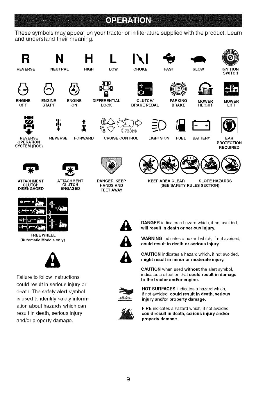
These symbols may appear on your tractor or in literature supplied with the product. Learn
and understand their meaning.
R N H L I',,I
REVERSE NEUTRAL HIGH LOW CHOKE FAST SLOW IGNITION
SWITCH
8 6 @
ENGINE ENGINE ENGINE DIFFERENTIAL
OFF START ON LOCK
CLUTCH/ MOWER
BRAKE PEDAL LIFT
PARKING MOWER
BRAKE HEIGHT
1414
REVERSE
OPERATION
SYSTEM(ROS)
REVERSE FORWARD
m
CRUISE CONTROL LIGHTS ON FUEL BATTERY EAR
PROTECTION
REQUIRED
ATTACHMENT ATTACHMENT DANGER, KEEP
CLUTCH CLUTCH HANDS AND
DISENGAGED ENGAGED FEET AWAY
FREE WHEEL
(Automatic Models only)
®@@@@
KEEP AREA CLEAR SLOPE HAZARDS
(SEE SAFETY RULES SECTION)
&
Failure to follow instructions
could result in serious injury or
death. The safety alert symbol
is used to identify safety inform-
ation about hazards which can
result in death, serious injury
and/or property damage.
&
&
&
DANGER indicates a hazard which, if not avoided,
will result in death or serious injury.
WARNING indicates a hazard which, if not avoided,
could result in death or serious injury.
CAUTION indicates a hazard which, if not avoided,
might result in minor or moderate injury.
CAUTION when used without the alert symbol,
indicates a situation that could result in damage
to the tractor and/or engine.
HOT SURFACES indicates a hazard which,
if not avoided, could result in death, serious
injury and/or property damage.
FIRE indicates a hazard which, if not avoided,
could result in death, serious injury and/or
property damage.
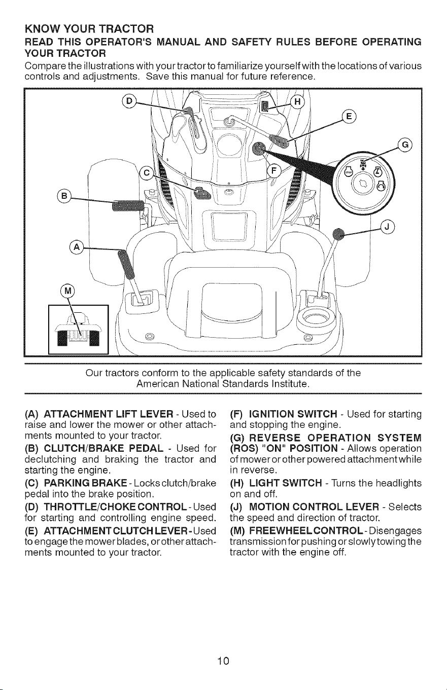
KNOW YOUR TRACTOR
READ THiS OPERATOR'S MANUAL AND SAFETY RULES BEFORE OPERATING
YOUR TRACTOR
Compare the illustrations with your tractor to familiarize yourself with the locations of various
controls and adjustments. Save this manual for future reference.
@o
Our tractors conform to the applicable safety standards of the
American National Standards Institute.
(A) ATTACHMENT LIFT LEVER - Used to
raise and lower the mower or other attach-
ments mounted to your tractor.
(B) CLUTCH/BRAKE PEDAL - Used for
dectutching and braking the tractor and
starting the engine.
(C) PARKING BRAKE- Locks clutch/brake
pedal into the brake position.
(D) THROTTLE/CHOKE CONTROL- Used
for starting and controlling engine speed.
(E) ATTACHMENT CLUTCH LEVER - Used
to engage the mower btades, or other attach-
ments mounted to your tractor.
(F) IGNITION SWITCH - Used for starting
and stopping the engine.
(G) REVERSE OPERATION SYSTEM
(ROS) "ON" POSiTiON - Allows operation
of mower or other powered attachment while
in reverse.
(H) LIGHT SWITCH - Turns the headlights
on and off.
(d) MOTION CONTROL LEVER - Selects
the speed and direction of tractor.
(M) FREEWHEELCONTROL- Disengages
transmission for pushing or slowtytowing the
tractor with the engine off.
10

The operation of any tractor can result in foreign objects thrown into
the eyes, which can result in severe eye damage. Always wear safety
glasses or eye shields while operating your tractor or performing any
adjustments or repairs. We recommend standard safety glasses or a
wide vision safety mask worn over spectacles.
HOW TO USE YOUR TRACTOR
TO SET PARKING BRAKE
Your tractor is equipped with an operator
presence sensing switch. When engine is
running, any attempt bythe operator to leave
the seat without first setting the parking brake
will shut off the engine.
1. Depress clutch/brake pedal (B) all the
way down and hold.
2. Putt parking brake lever (C) up and hold,
release pressure from clutch/brake pedal
(B), then release parking brake lever. Ped-
al should remain in brake position. Ensure
parking brake will hold tractor secure.
STOPPING
MOWER BLADES -
• To stop mower blades, move attachment
clutch controlto disengaged position (t_l).
• Turn ignition key (F) to "STOP" position
and remove key. Always remove key when
leaving tractor to prevent unauthorized use.
• Never use choke to stop engine.
IMPORTANT." Leaving the ignition switch in
any position other than "STOP" will cause the
battery to discharge and go dead.
NOTE: Under certain conditions when tractor
is standing idle with the engine running, hot
engine exhaust gases may cause "brown-
ing" of grass. To eliminate this possibility,
always stop engine when stopping tractor
on grass areas.
CAUTION: Always stop tractor com-
pletely, as described above, before leaving
the operator's position.
TO USE THROTTLE CONTROL (D)
Always operate engine at full speed (fast).
• Operating engine at less than full speed
(fast) reduces engine's operating efficiency.
• Full speed (fast) offers the best mower
performance.
(1"_) Attachment (1_"1) Attachment
Clutch Control Clutch Control
"Engaged .... Disengaged"
GROUND DRIVE -
• To stop ground drive, depress brake pedal
all the way down.
• Move motion control lever to neutral posi-
tion.
ENGINE -
• Move throttle control (D) between half and
full speed (fast) position.
NOTE: Failure to move throttle control be-
tween half and full speed (fast) position, be-
fore stopping, may cause engine to"backfire".
TO MOVE FORWARD AND
BACKWARD
The direction and speed of movement is
controlled by the motion control lever. (J)
1. Start tractor with motion control lever in
neutral position.
2. Release parking brake.
3. Slowly move motion control lever to
desired position.
11
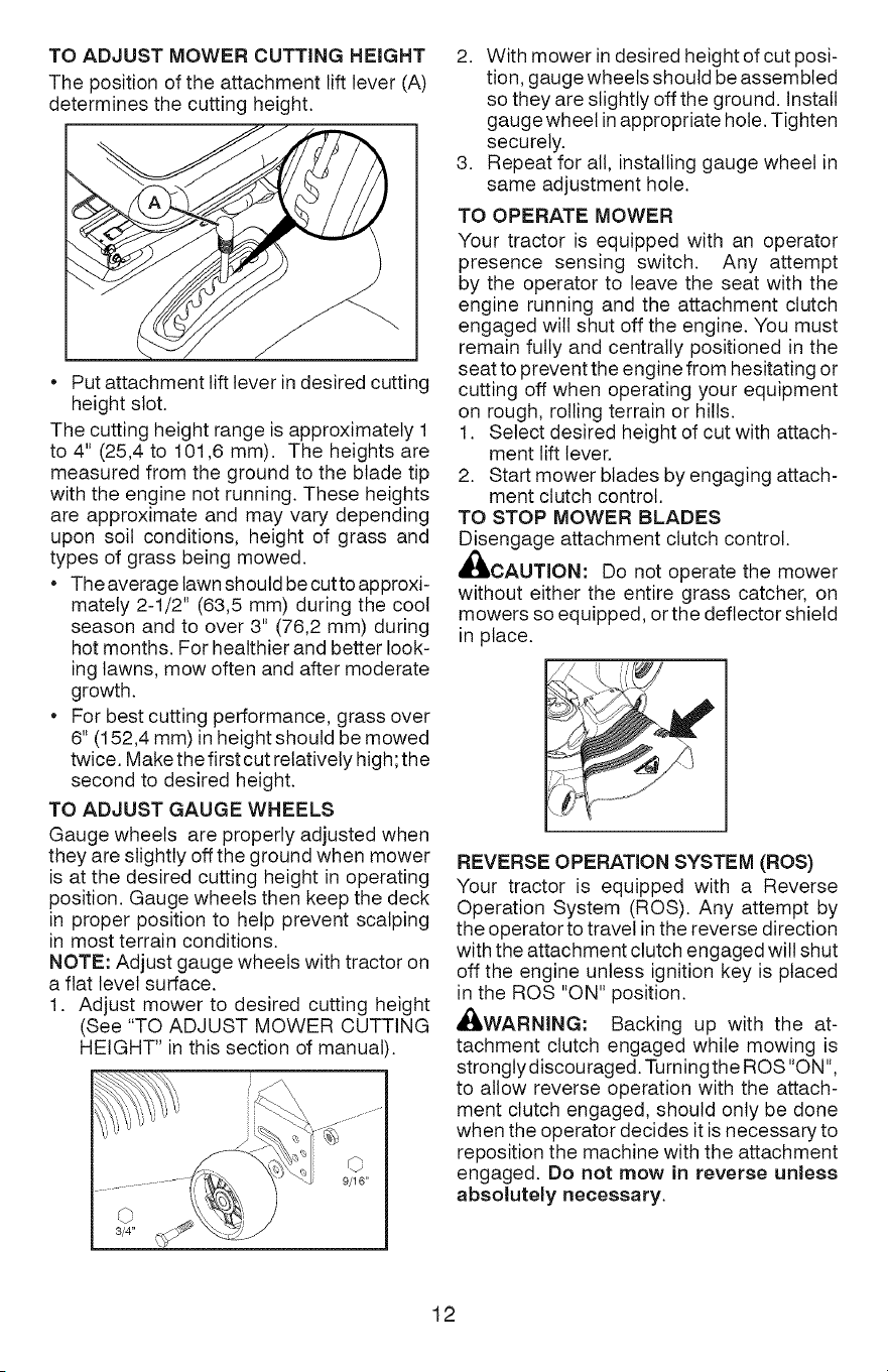
TO ADJUST MOWER CUTTING HEIGHT
The position of the attachment lift lever (A)
determines the cutting height.
Put attachment lift lever in desired cutting
height slot.
The cutting height range is approximately 1
to 4" (25,4 to 101,6 mm). The heights are
measured from the ground to the blade tip
with the engine not running. These heights
are approximate and may vary depending
upon soil conditions, height of grass and
types of grass being mowed.
The average lawn should be cutto approxi-
mately 2-1/2" (63,5 mm) during the cool
season and to over 3" (76,2 mm) during
hot months. For healthier and better look-
ing lawns, mow often and after moderate
growth.
For best cutting performance, grass over
6" (152,4 mm) in height should be mowed
twice. Make the first cut relatively high; the
second to desired height.
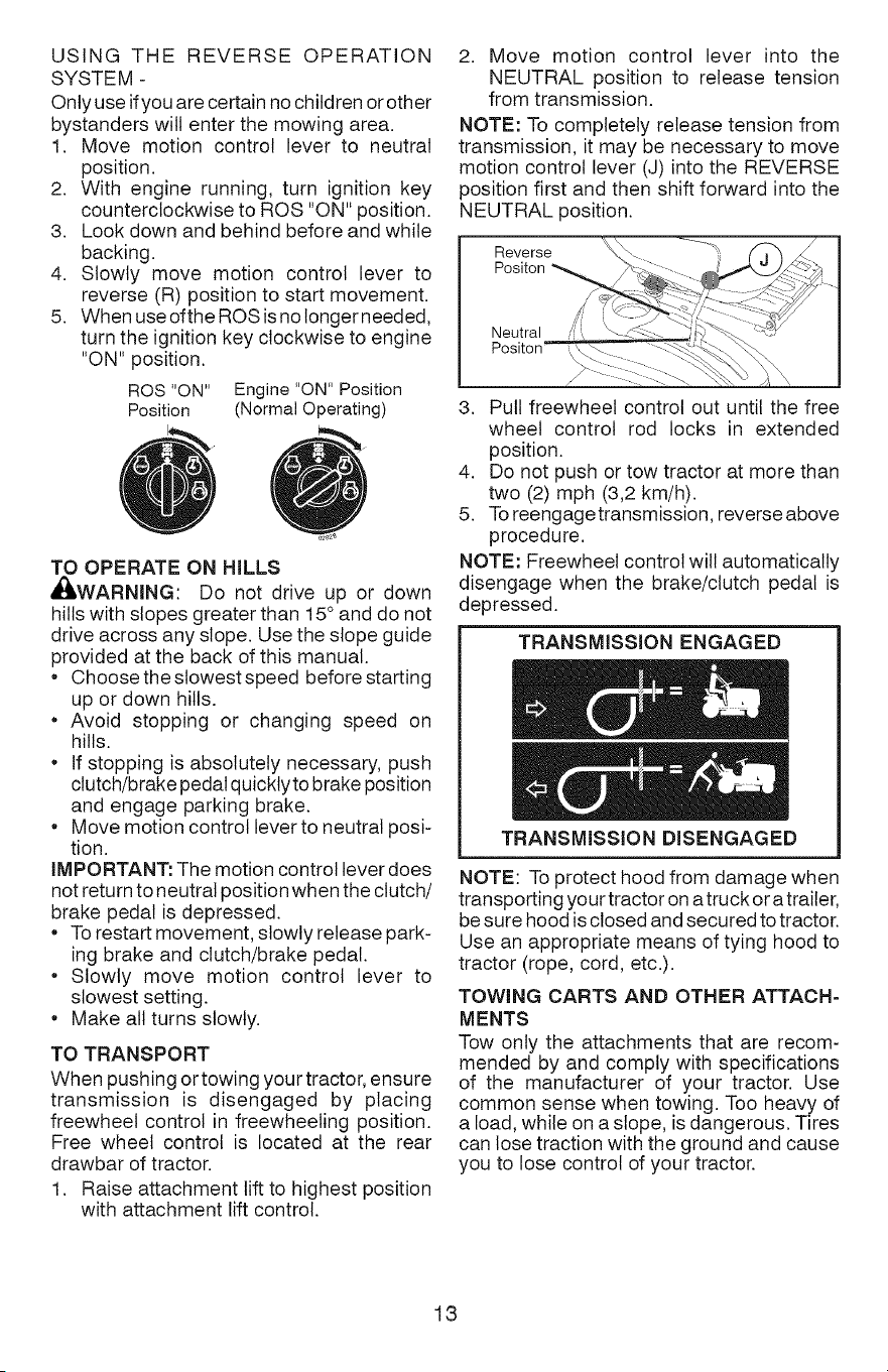
TO ADJUST GAUGE WHEELS
Gauge wheels are properly adjusted when
they are slightly off the ground when mower
is at the desired cutting height in operating
position. Gauge wheels then keep the deck
in proper position to help prevent scalping
in most terrain conditions.
NOTE: Adjust gauge wheels with tractor on
a flat level surface.
1. Adjust mower to desired cutting height
(See "TO ADJUST MOWER CUTTING
HEIGHT" in this section of manual).
2. With mower in desired height of cut posi-
tion, gauge wheels should be assembled
so they are slightly off the ground. Install
gauge wheel in appropriate hole. Tighten
securely.
3. Repeat for all, installing gauge wheel in
same adjustment hole.
TO OPERATE MOWER
Your tractor is equipped with an operator
presence sensing switch. Any attempt
by the operator to leave the seat with the
engine running and the attachment clutch
engaged wilt shut off the engine. You must
remain fully and centrally positioned in the
seat to prevent the engine from hesitating or
cutting off when operating your equipment
on rough, rolling terrain or hills.
1. Select desired height of cut with attach-
ment lift lever.
2. Start mower blades by engaging attach-
ment clutch control.
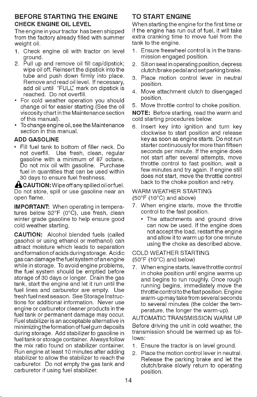
TO STOP MOWER BLADES
Disengage attachment clutch control.
d_I,CAUTION: Do not operate the mower
without either the entire grass catcher, on
mowers so equipped, or the deflector shield
in place.
REVERSE OPERATION SYSTEM (ROS)
Your tractor is equipped with a Reverse
Operation System (ROS). Any attempt by
the operator to travel in the reverse direction
with the attachment clutch engaged will shut
off the engine unless ignition key is placed
in the ROS "ON" position.
_WARNING: Backing up with the at-
tachment clutch engaged while mowing is
strongly discouraged. Turning the ROS "ON",
to allow reverse operation with the attach-
ment clutch engaged, should only be done
when the operator decides it is necessary to
reposition the machine with the attachment
engaged. Do not mow in reverse unless
absolutely necessary.
12
USING THE REVERSE OPERATION
SYSTEM -
Only use if you are certain no children or other
bystanders will enter the mowing area.
1. Move motion control lever to neutral
position.
2. With engine running, turn ignition key
counterclockwise to ROS "ON" position.
3. Look down and behind before and while
backing.
4. Slowly move motion control lever to
reverse (R) position to start movement.
5. When use ofthe ROS is no longer needed,
turn the ignition key clockwise to engine
"ON" position.
ROS "ON" Engine "ON" Position
Position (Normal Operating)
TO OPERATE ON HILLS
,dI_,WARNING: Do not drive up or down
hills with slopes greater than 15° and do not
drive across any slope. Use the slope guide
provided at the back of this manual.
• Choose the slowest speed before starting
up or down hills.
• Avoid stopping or changing speed on
hills.
• If stopping is absolutely necessary, push
clutch/brake pedal quicklyto brake position
and engage parking brake.
• Move motion control lever to neutral posi-
tion.
iMPORTANT: The motion control lever does
not return to neutral position when the clutch/
brake pedal is depressed.
• To restart movement, slowly release park-
ing brake and clutch/brake pedal.
• Slowly move motion control lever to
slowest setting.
• Make all turns slowly.
TO TRANSPORT
When pushing or towing your tractor, ensure
transmission is disengaged by placing
freewheel control in freewheeling position.
Free wheel control is located at the rear
drawbar of tractor.
1. Raise attachment lift to highest position
with attachment lift control.
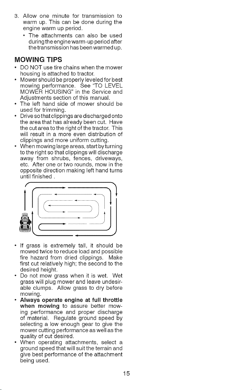
2. Move motion control lever into the
NEUTRAL position to release tension
from transmission.
NOTE: To completely release tension from
transmission, it may be necessary to move
motion control lever (J) into the REVERSE
position first and then shift forward into the
NEUTRAL position.
Reverse
Positon
Neutral
3. Pull freewheel control out until the free
wheel control rod locks in extended
position.
4. Do not push or tow tractor at more than
two (2) mph (3,2 km/h).
5. Toreengagetransmission, reverse above
procedure.
NOTE: Freewheel control will automatically
disengage when the brake/clutch pedal is
depressed.
TRANSMISSION ENGAGED
TRANSMiSSiON DISENGAGED
NOTE: To protect hood from damage when
transporting your tractor on a truck or a trailer,
be sure hood is closed and secured to tractor.
Use an appropriate means of tying hood to
tractor (rope, cord, etc.).
TOWING CARTS AND OTHER ATTACH-
MENTS
Tow only the attachments that are recom-
mended by and comply with specifications
of the manufacturer of your tractor. Use
common sense when towing. Too heavy of
a load, while on a slope, is dangerous. Tires
can lose traction with the ground and cause
you to lose control of your tractor.
13
BEFORE STARTING THE ENGINE
CHECK ENGINE OiL LEVEL
The engine in your tractor has been shipped
from the factory already filled with summer
weight oil.
1. Check engine oil with tractor on level
ground.
2. Putt up and remove oil fill cap/dipstick;
wipe oil off. Reinsert the dipstick into the
tube and push down firmly into place.
Remove and read oil level. If necessary,
add oil until "FULE' mark on dipstick is
reached. Do not overfill.
• For cold weather operation you should
change oil for easier starting (See the oil
viscosity chart in the Maintenance section
of this manual).
To change engine oil, see the Maintenance
section in this manual.
ADD GASOLINE
* Fill fuel tank to bottom of filler neck. Do
not overfill. Use fresh, clean, regular
gasoline with a minimum of 87 octane.
Do not mix oil with gasoline. Purchase
fuel in quantities that can be used within
30 days to ensure fuel freshness.
_ CAUTION: Wipe off any spilled oil or fuet.
Do not store, spill or use gasoline near an
open flame.
IMPORTANT: When operating in tempera-
tures below 32°F (0°C), use fresh, clean
winter grade gasoline to help ensure good
cold weather starting.
CAUTION: Alcohol blended fuels (called
gasohol or using ethanol or methanol) can
attract moisture which leads to separation
and formation of acids during storage. Acidic
gas can damage the fuel system of an engine
while in storage. To avoid engine problems,
the fuel system should be emptied before
storage of 30 days or longer. Drain the gas
tank, start the engine and let it run until the
fuel lines and carburetor are empty. Use
fresh fuel next season. See Storage Instruc-
tions for additional information. Never use
engine or carburetor cleaner products in the
fuel tank or permanent damage may occur.
Fuel stabilizer is an acceptable alternative in
minimizing the formation of fuet gum deposits
during storage. Add stabilizer to gasoline in
fuel tank or storage container. Always follow
the mix ratio found on stabilizer container.
Run engine at least 10 minutes after adding
stabilizer to allow the stabilizer to reach the
carburetor. Do not empty the gas tank and
carburetor if using fuel stabilizer.
14
TO START ENGINE
When starting the engine for the first time or
if the engine has run out of fuel, it will take
extra cranking time to move fuel from the
tank to the engine.
1. Ensure freewheel control is in the trans-
mission engaged position.
2. Sit on seat in operating position, depress
clutch/brake pedal and set parking brake.
3. Place motion control lever in neutral
position.
4. Move attachment clutch to disengaged
position.
5. Move throttle control to choke position.
NOTE: Before starting, read the warm and
cold starting procedures below.
6. Insert key into ignition and turn key
clockwise to start position and release
key as soon as engine starts. Do not run
starter continuously for more than fifteen
seconds per minute. If the engine does
not start after several attempts, move
throttle control to fast position, wait a
few minutes and try again. If engine still
does not start, move the throttle control
back to the choke position and retry.
WARM WEATHER STARTING
(50°F (10°C) and above)
7. When engine starts, move the throttle
control to the fast position.
* The attachments and ground drive
can now be used. If the engine does
not accept the load, restart the engine
and allow it to warm up for one minute
using the choke as described above.
COLD WEATHER STARTING
(50°F (10°0) and below)
7. When engine starts, leavethrottle control
in choke position until engine warms up
and begins to run roughly. Once rough
running begins, immediately move the
throttle control to the fast position. Engine
warm-up may take from several seconds
to several minutes (the colder the tem-
perature, the longer the warm-up).
AUTOMATIC TRANSMISSION WARM UP
Before driving the unit in cold weather, the
transmission should be warmed up as fol-
lows:
1. Ensure the tractor is on level ground.
2. Place the motion control lever in neutral.
Release the parking brake and let the
clutch/brake slowly return to operating
position.
3. Allowoneminutefortransmissionto
warmup.Thiscanbedoneduringthe
enginewarmupperiod.
Theattachmentscanalsobeused
duringtheenginewarm-upperiodafter
thetransmissionhasbeenwarmedup.
MOWING TIPS
• DO NOT use tire chains when the mower
housing is attached to tractor.
Mower should be properly leveled for best
mowing performance. See "TO LEVEL
MOWER HOUSING" in the Service and
Adjustments section of this manual.
The left hand side of mower should be
used for trimming.
Drive so that clippings are discharged onto
the area that has already been cut. Have
the cut area to the right of the tractor. This
will result in a more even distribution of
clippings and more uniform cutting.
When mowing large areas, start byturning
to the right so that clippings will discharge
away from shrubs, fences, driveways,
etc. After one or two rounds, mow in the
opposite direction making left hand turns
until finished.
If grass is extremely tall, it should be
mowed twice to reduce toad and possible
fire hazard from dried clippings. Make
first cut relatively high; the second to the
desired height.
Do not mow grass when it is wet. Wet
grass will plug mower and leave undesir-
able clumps. Allow grass to dry before
mowing.
Always operate engine at full throttle
when mowing to assure better mow-
ing performance and proper discharge
of material. Regulate ground speed by
selecting a low enough gear to give the
mower cutting performance as well as the
quality of cut desired.
• When operating attachments, select a
ground speed that will suit the terrain and
give best performance of the attachment
being used.
15
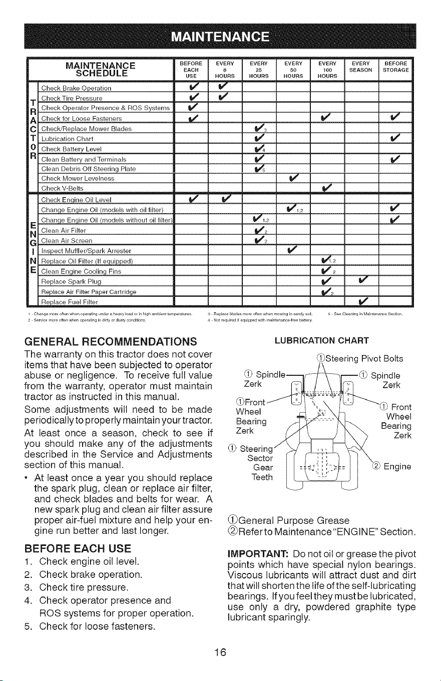
BEFORE EVERY
EACH 8
USE HOURS
v
¥,
EVERY25 EVERY EVERY100
HOURS HOURS HOURS
I/
_4
v"
MAINTENANCE EVERY BEFORE
SCHEDULE SEASON STORAGE
m
Check Brake Operation
Check Tire Pressure
T Check Operator Presence & ROS Systems
A Check for Loose Fasteners
C Check/Replace Mower Blades
| Lubrication Chart
0 Check Battery Level
R Clean Battery and Terminals
Clean Debris Off Steering Plate
Check Mower Levelness
Check V-Belts
Check Enqine Oil Level
Change Engine Oil (models with oil filter) _1,2
Change Engine Oil (models without oil filter 11##'1,2
NE Clean Air Filter _2
G Clean Air Screen t##'2
Inspect Muffler/Spark Arrester
N Replace Oil Filter (If equipped) _,2
E Clean Engine Cooling Fins _4' 2
Replace Spark Plug _
Replace Air Filter Paper Cartrid,ge t,_2
-- R_place Fuel Filter .... _ __
Ch_ngemoreoftenwhenoperatingunder_heavy_oadofinhighambienttemperatures 3 Rela_oebl_desmoreoftenwhenmowJngil_sandysoiE 5 SeeClea_lingir_Mair_ter_anceSectiotl
2 Servicemofeoftel_whenoperatingil_dJrtyordustyoortditions 4 Notrequiredilequila_aedwithmaintensn_freebattery
GENERAL RECOMMENDATIONS
The warranty on this tractor does not cover
items that have been subjected to operator
abuse or negligence. To receive full value
from the warranty, operator must maintain
tractor as instructed in this manual.
Some adjustments will need to be made
periodically to properly maintain your tractor.
At least once a season, check to see if
you should make any of the adjustments
described in the Service and Adjustments
section of this manual.
• At least once a year you should replace
the spark plug, clean or replace air filter,
and check blades and belts for wear. A
new spark plug and clean air filter assure
proper air-fuel mixture and help your en-
gine run better and last longer.
BEFORE EACH USE
1. Check engine oil level.
2. Check brake operation.
3. Check tire pressure.
4. Check operator presence and
ROB systems for proper operation.
5. Check for loose fasteners.
LUBRICATION CHART
_Steering Pivot Bolts
d_
Zerk Zerk
Wheel
Bearing /-_
Zerk
(_ Steering _
Sector I I
Gear I I
Teeth ___
Front
Wheel
Bearing
Zerk
Engine
(_General Purpose Grease
@Refer to Maintenance "ENGINE" Section.
IMPORTANT: Do not oil or grease the pivot
points which have special nylon bearings.
Viscous lubricants will attract dust and dirt
that will shorten the life of the self-lubricating
bearings. If you feet they must be lubricated,
use only a dry, powdered graphite type
lubricant sparingly.
16

TRACTOR
Always observe safety rules when perform-
ing any maintenance.
BRAKE OPERATION
If tractor requires more than 5 feet (1,5 m)
to stop at highest speed in highest gear on
a level, dry concrete or paved surface, then
brake must be serviced. (See "TO CHECK
BRAKE" in the Service and Adjustments
section of this manual).
TIRES
• Maintain proper air pressure in all tires
(See the side of tires for proper PSI.)
Keep tires free of gasoline, oil, or insect
control chemicals which can harm rubber.
Avoid stumps, stones, deep ruts, sharp
objects and other hazards that may cause
tire damage.
NOTE: To seal tire punctures and prevent
flat tires due to slow leaks, tire sealant may
be purchased from your local parts dealer.
Tire sealant also prevents tire dry rot and
corrosion.
OPERATOR PRESENCE SYSTEM AND
REVERSE OPERATION SYSTEM (ROS)
Be sure operator presence and reverse
operation systems are working properly. If
your tractor does not function as described,
repair the problem immediately.
• The engine should not start unless the
brake pedal is fully depressed, and the
attachment clutch control is in the disen-
gaged position.
CHECK OPERATOR PRESENCE SYSTEM
• When the engine is running, any attempt
by the operator to leave the seat without
first setting the parking brake should shut
off the engine.
• When the engine is running and the at-
tachment clutch is engaged, any attempt
by the operator to leave the seat should
shut off the engine.
• The attachment clutch should never oper-
ate unless the operator is in the seat.
CHECK REVERSE OPERATION (ROS)
SYSTEM
• When the engine is running with the ignition
switch inthe engine "ON" position and the
attachment clutch engaged, any attempt
by the operator to drive in reverse should
shut off the engine.
• When the engine is running with the ignition
switch in the ROS "ON" position and the
attachment clutch engaged, any attempt
by the operator to drive in reverse should
NOT shut off the engine.
Ros "On" Engine "On" Position
Position (Normal Operating)
BLADE CARE
For best results mower blades must be sharp.
Replace worn, bent or damaged blades.
_, CAUTION: Use only a replacement blade
approved bythe manufacturer of your tractor.
Using a blade not approved by the manu-
facturer of your tractor is hazardous, could
damage your tractor and void your warranty.
BLADE REMOVAL
1. Raise mower to highest position to allow
access to blades.
NOTE: Protect your hands with gloves and/
or wrap blade with heavy cloth.
2. Remove blade bolt by turning counter-
clockwise.
3. install new blade with stamped "GRASS
SIDE" facing the ground.
iMPORTANT: To ensure proper assembly,
center hole in blade must align with star on
mandrel assembly.
4. install and tighten blade bolt securely
(45-55 Ft. Lbs./62-75 Nm).
iMPORTANT: Special blade bolt is heat
treated.
Star
Center Hole \
Blade Bolt "_ Mandrel
(Special) -...._.d_/ Assembly
Blade
BATTERY
Your tractor has a battery charging system
which is sufficient for normal use. However,
periodic charging of the battery with an au-
tomotive charger will extend its life.
• Keep battery and terminals clean.
• Keep battery bolts tight.
• Keep small vent holes open.
• Recharge at 6-10 amperes for 1 hour.
NOTE: The original equipment battery on
your tractor is maintenance free. Do not
attempt to open or remove caps or covers.
Adding or checking level of electrolyte is
not necessary.
17
TOCLEANBATTERYANDTERMINALS
Corrosionanddirtonthebatteryandterminals
cancausethebatteryto"leak"power.
1. Removeterminalguard.
2. DisconnectBLACKbatterycablefirst
thenRED batterycableandremove
batteryfromtractor.
3. Rinsethebatterywithplainwaterand
dry.
4. Cleanterminalsandbatterycableends
withwirebrushuntilbright.
5. Coatterminalswithgreaseorpetroleum
jelly.
6. Reinstallbattery(See"REPLACING
BATTERY"intheServiceandAdjust-
mentssectionofthismanual).
TRANSAXLE MAINTENANCE
The transaxle was sealed at the factory and
fluid maintenance is not required for the life
of the transaxle. Should the transaxle ever
leak or require servicing, contact your near-
est Sears or other qualified service center.
V=BELTS
Check V-belts for deterioration and wear after
100 hours of operation and replace if neces-
sary. The belts are not adjustable. Replace
belts if they begin to slip from wear.
ENGINE
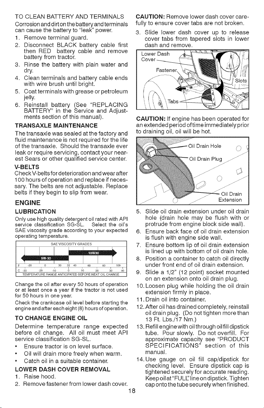
CAUTION: Remove lower dash cover care-
fully to ensure cover tabs are not broken.
3. Slide lower dash cover up to release
cover tabs from tapered slots in lower
dash and remove.
Lower Dash
CAUTION: If engine has been operated for
an extended period oftime immediately prior
to draining oil, oil will be hot.
Drain Hole
Oil Drain
Extension
LU BRICATION
Only use high quality detergent oil rated with API
service classification SG-SL. Select the oil's
SAE viscosity grade according to your expected
operating temperature.
SAE VISCOSITY GRADES
C -30 _20 qo 0 10 20 3o 40
TEMPERATURE RANGE ANTICIPATED BEFORE NEXT OIL CHANGE
Change the oil after every 50 hours of operation
or at least once a year if the tractor is not used
for 50 hours in one year.
Check the crankcase oil level before starting the
engine and after each eight (8) hours of operation.
TO CHANGE ENGINE OiL
Determine temperature range expected
before oil change. All oil must meet API
service classification SG-SL.
• Ensure tractor is on level surface.
• Oil will drain more freely when warm.
• Catch oil in a suitable container.
LOWER DASH COVER REMOVAL
1. Raise hood.
2. Remove fastenerfrom lower dash cover.
5. Slide oil drain extension under oil drain
hole (drain hole may be flush with or
protrude from engine block side wall).
6. Ensure back face of oil drain extension
is flush with engine side wall.
7. Ensure bottom lip of oil drain extension
is lined up with bottom of oil drain hole.
8. Position a container to catch oil directly
under front end of oil drain extension.
9. Slide a 1/2" (12 point) socket mounted
on an extension onto oil drain plug.
10. Loosen plug while holding the oil drain
extension firmly in place.
11. Drain oil into container.
12.After oil has drained completely, reinstall
oil drain plug. (Do not tighten more than
13 Ft. Lbs./17 Nm.)
13. Refill engine with oitthrough oil fill dipstick
tube. Pour slowly. Do not overfill. For
approximate capacity see "PRODUCT
SPECIFICATIONS" section of this
manual.
14. Use gauge on oil fill cap/dipstick for
checking level. Ensure dipstick cap is
tightened securely for accurate reading.
Keep oilat"FU LE'line on dipstick. Tighten
cap ontothetube securely when finished.
18
ENGINE OiL FILTER
Replace the engine oil filter every season or
every other oil change if the tractor is used
more than 100 hours in one year.
NOTE: If needed, remove lower dash covers
using steps from "Lower dash cover removal"
section of this manual.
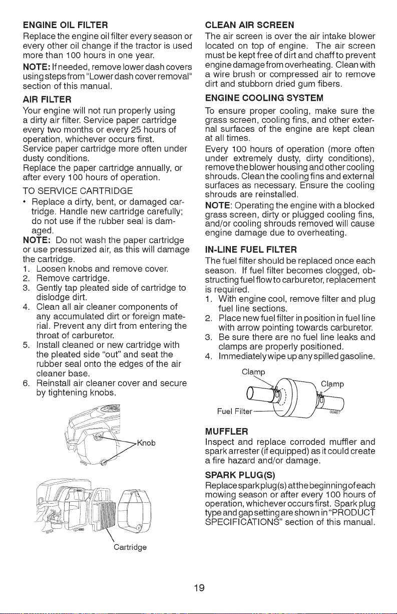
AiR FILTER
Your engine will not run properly using
a dirty air filter. Service paper cartridge
every two months or every 25 hours of
operation, whichever occurs first.
Service paper cartridge more often under
dusty conditions.
Replace the paper cartridge annually, or
after every 100 hours of operation.
TO SERVICE CARTRIDGE
Replace a dirty, bent, or damaged car-
tridge. Handle new cartridge carefully;
do not use if the rubber seal is dam-
aged.
NOTE: Do not wash the paper cartridge
or use pressurized air, as this will damage
the cartridge.
1. Loosen knobs and remove cover.
2. Remove cartridge.
3. Gently tap pleated side of cartridge to
dislodge dirt.
4. Clean alt air cleaner components of
any accumulated dirt or foreign mate-
rial. Prevent any dirt from entering the
throat of carburetor.
5. Install cleaned or new cartridge with
the pleated side "out" and seat the
rubber seal onto the edges of the air
cleaner base.
6. Reinstall air cleaner cover and secure
by tightening knobs.
CLEAN AiR SCREEN
The air screen is over the air intake blower
located on top of engine. The air screen
must be kept free of dirt and chaff to prevent
engine damage from overheating. Clean with
a wire brush or compressed air to remove
dirt and stubborn dried gum fibers.
ENGINE COOLING SYSTEM
To ensure proper cooling, make sure the
grass screen, cooling fins, and other exter-
nal surfaces of the engine are kept clean
at all times.
Every 100 hours of operation (more often
under extremely dusty, dirty conditions),
remove the blower housing and other cooling
shrouds. Clean the cooling fins and external
surfaces as necessary. Ensure the cooling
shrouds are reinstalled.
NOTE: Operating the engine with a blocked
grass screen, dirty or plugged cooling fins,
and/or cooling shrouds removed will cause
engine damage due to overheating.
IN=LINE FUEL FILTER
The fuel filter should be replaced once each
season. If fuel filter becomes clogged, ob-
structing fuel flowto carburetor, replacement
is required.
1. With engine cool, remove filter and plug
fuel line sections.
2. Place new fuetfilter in position in fuel line
with arrow pointing towards carburetor.
3. Be sure there are no fuel line leaks and
clamps are properly positioned.
4. Immediatetywipe up anyspilled gasoline.
Clamp
Fuel Filt_
MUFFLER
inspect and replace corroded muffler and
spark arrester (if equipped) as it could create
a fire hazard and/or damage.
SPARK PLUG(S)
Replace spark plug(s) atthe beginning of each
mowing season or after every 100 hours of
operation, whichever occurs first. Spark plug
type and gap setting are shown in "PROD UCT
SPECIFICATIONS" section of this manual.
Cartridge
19
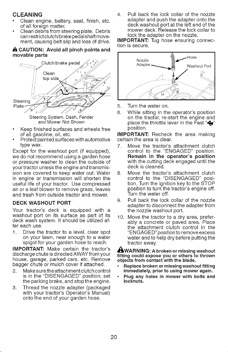
CLEANING
• Clean engine, battery, seat, finish, etc.
of all foreign matter.
• Clean debris from steering plate. Debris
can restrict clutch/brake pedal shaft move-
ment, causing belt slip and loss of drive.
_, CAUTION: Avoid all pinch points and
movable parts
Clutch/brake pedal
// Clean
4. Pull back the lock collar of the nozzle
adapter and push the adapter onto the
deck washout port at the left end of the
mower deck. Release the lock collar to
lock the adapter on the nozzle.
IMPORTANT: Tug hose ensuring connec-
tion is secure.
Nozzle _.,,,,_ Hose
Adapter _ Washout Port
Steering
Steering System, Dash, Fender
and Mower Not Shown
• Keep finished surfaces and wheels free
of all gasoline, oil, etc.
• Protectpaintedsurfaceswithautomotive
type wax.
Except for the washout port (if equipped),
we do not recommend using a garden hose
or pressure washer to clean the outside of
your tractor unless the engine and transmis-
sion are covered to keep water out. Water
in engine or transmission will shorten the
useful life of your tractor. Use compressed
air or a leaf blower to remove grass, leaves
and trash from outside tractor and mower.
DECK WASHOUT PORT
Your tractor's deck is equipped with a
washout port on its surface as part of its
deck wash system. It should be utilized af-
ter each use.
1. Drive the tractor to a level, clear spot
on your lawn, near enough to a water
spigot for your garden hose to reach.
IMPORTANT: Make certain the tractor's
discharge chute is directed AWAY from your
house, garage, parked cars, etc. Remove
bagger chute or mulch cover if attached.
2. Make sure the attachment clutch control
is in the "DISENGAGED" position, set
the parking brake, and stop the engine.
3. Thread the nozzle adapter (packaged
with your tractor's Operator's Manual)
onto the end of your garden hose.
5. Turn the water on.
6. While sitting in the operator's position
on the tractor, re-start the engine and
place the throttle lever in the Fast ",_"
position.
IMPORTANT: Recheck the area making
certain the area is clear.
7. Move the tractor's attachment clutch
control to the "ENGAGED" position.
Remain in the operator's position
with the cutting deck engaged until the
deck is cleaned.
8. Move the tractor's attachment clutch
control to the "DISENGAGED" posi-
tion. Turn the ignition key to the STOP
position to turn the tractor's engine off.
Turn the water off.
9. Pull back the lock collar of the nozzle
adapter to disconnect the adapter from
the nozzle washout port.
10. Move the tractor to a dry area, prefer-
ably a concrete or paved area. Place
the attachment clutch control in the
"ENGAGED" position to remove excess
water and to help dry before putting the
tractor away.
_,WARNING: A broken or missing washout
fitting could expose you or others to thrown
objects from contact with the blade.
Replace broken or missing washout fitting
immediately, prior to using mower again.
Plug any holes in mower with bolts and
Ioeknuts,
20
WARNING: TO AVOID SERIOUS iNJURY, BEFORE PERFORMING ANY
SERVICE OR ADJUSTMENTS:
1. Depress clutch/brake pedal fully and set parking brake.
2. Place motion control lever in neutral position.
3. Place attachment clutch in "DISENGAGED" position.
4. Turn ignition key to "STOP" and remove key.
5. Ensure the blades and all moving parts have completely stopped.
6. Disconnect spark plug wire from spark plug and place wire where it cannot
come in contact with plug.
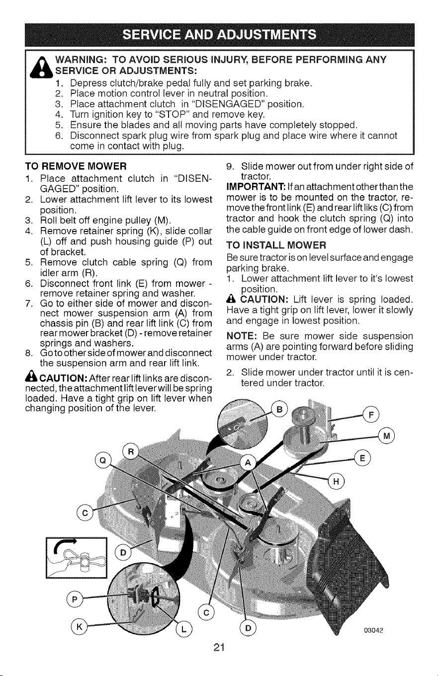
TO REMOVE MOWER
1. Place attachment clutch in "DISEN-
GAGED" position.
2. Lower attachment lift lever to its lowest
position.
3. Roll belt off engine pulley (M).
4. Remove retainer spring (K), slide collar
(L) off and push housing guide (P) out
of bracket.
5. Remove clutch cable spring (Q) from
idler arm (R).
6. Disconnect front link (E) from mower -
remove retainer spring and washer.
7. Go to either side of mower and discon-
nect mower suspension arm (A) from
chassis pin (B) and rear lift link (C) from
rear mower bracket (D) - remove retainer
springs and washers.
8. Go to other side of mower and disconnect
the suspension arm and rear lift link.
CAUTION: After rear lift links are discon-
nected, the attachment lift lever will be spring
loaded. Have a tight grip on lift lever when
changing position of the lever.
9. Slide mower out from under right side of
tractor.
IMPORTANT: Ifan attachment other than the
mower is to be mounted on the tractor, re-
move the front link (E) and rear lift liks (C) from
tractor and hook the clutch spring (Q) into
the cable guide on front edge of lower dash.
TO iNSTALL MOWER
Be sure tractor is on level surface and engage
parking brake.
1. Lower attachment lift lever to it's lowest
position.
_, CAUTION: Lift lever is spring loaded.
Have a tight grip on lift lever, lower it slowly
and engage in lowest position.
NOTE: Be sure mower side suspension
arms (A) are pointing forward before sliding
mower under tractor.
2. Slide mower under tractor until it is cen-
tered under tractor.
21
03042
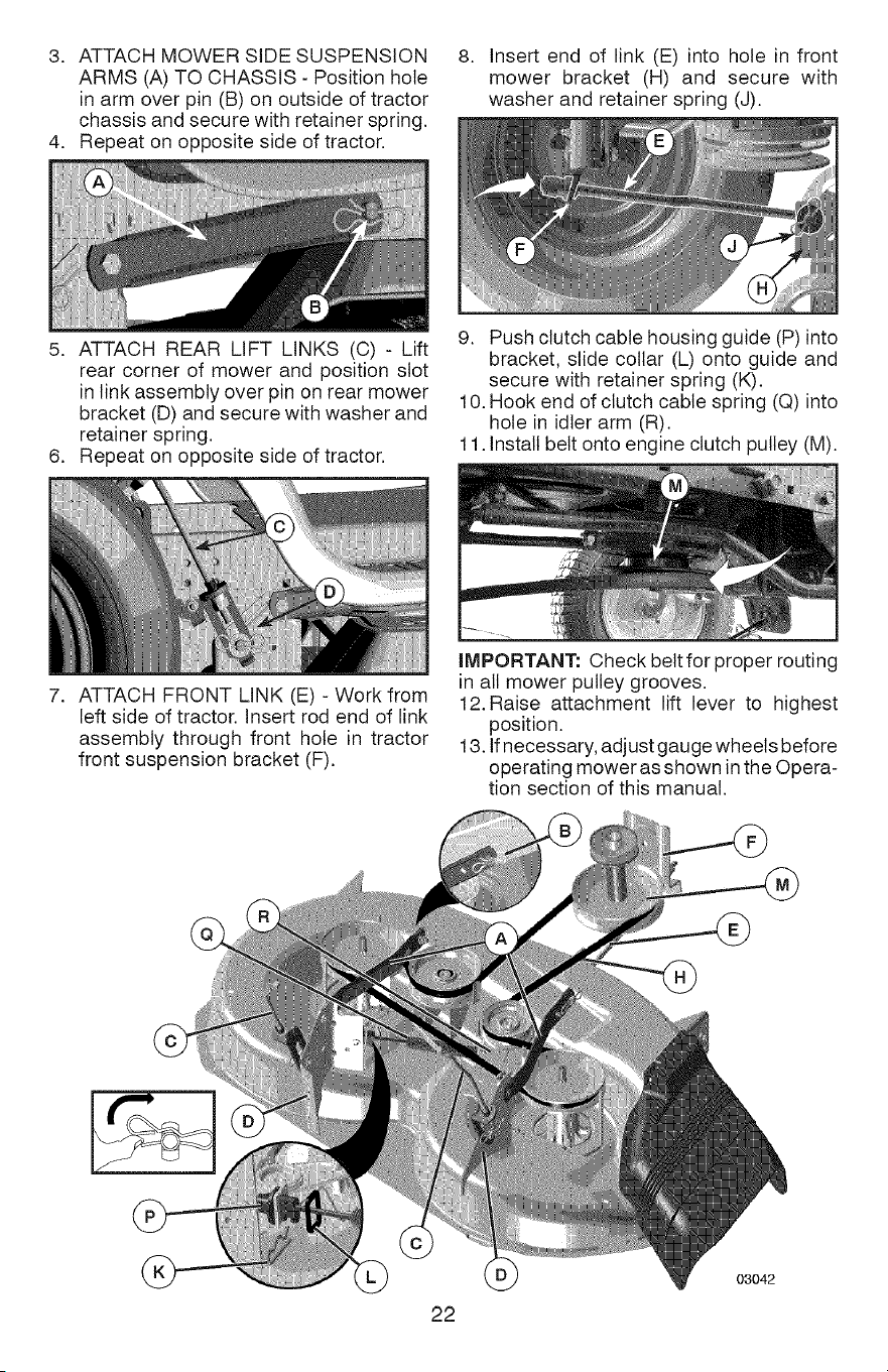
3. ATTACH MOWER SIDE SUSPENSION
ARMS (A) TO CHASSIS - Position hole
in arm over pin (B) on outside of tractor
chassis and secure with retainer spring.
4. Repeat on opposite side of tractor.
8. Insert end of link (E) into hole in front
mower bracket (H) and secure with
washer and retainer spring (J).
5. ATTACH REAR LIFT LINKS (C) - Lift
rear corner of mower and position slot
in link assembly over pin on rear mower
bracket (D) and secure with washer and
retainer spring.
6. Repeat on opposite side of tractor.
9. Push clutch cable housing guide (P) into
bracket, slide collar (L) onto guide and
secure with retainer spring (K).
10. Hook end of clutch cable spring (Q) into
hole in idler arm (R).
11. Install belt onto engine clutch pulley (M).
7.
ATTACH FRONT LINK (E) - Work from
left side of tractor. Insert rod end of link
assembly through front hole in tractor
front suspension bracket (F).
IMPORTANT: Check belt for proper routing
in all mower pulley grooves.
12. Raise attachment lift lever to highest
position.
13. If necessary, adjust gauge wheels before
operating mower as shown in the Opera-
tion section of this manual.
22
03042
TO LEVEL MOWER
Ensure tires are properly inflated to the PSi
shown on tires. If tires are over or under
inflated, it may affect the appearance of your
lawn and lead you to think the mower is not
adjusted properly.
VISUAL SIDE-TO-SIDE ADJUSTMENT
1. With all tires properly inflated and if your
lawn appears unevenly cut, determine
which side of mower is cutting lower.
NOTE: As desired, you can raise the low
side of mower or lower the high side.
2. Go to side of mower you wish to adjust.
3. With a 3/4" or adjustable wrench, turn
lift link adjustment nut (A) to the left to
lower the mower, or, to the right to raise
the mower.
5. Recheck measurements; adjust if neces-
sary until both sides are equal.
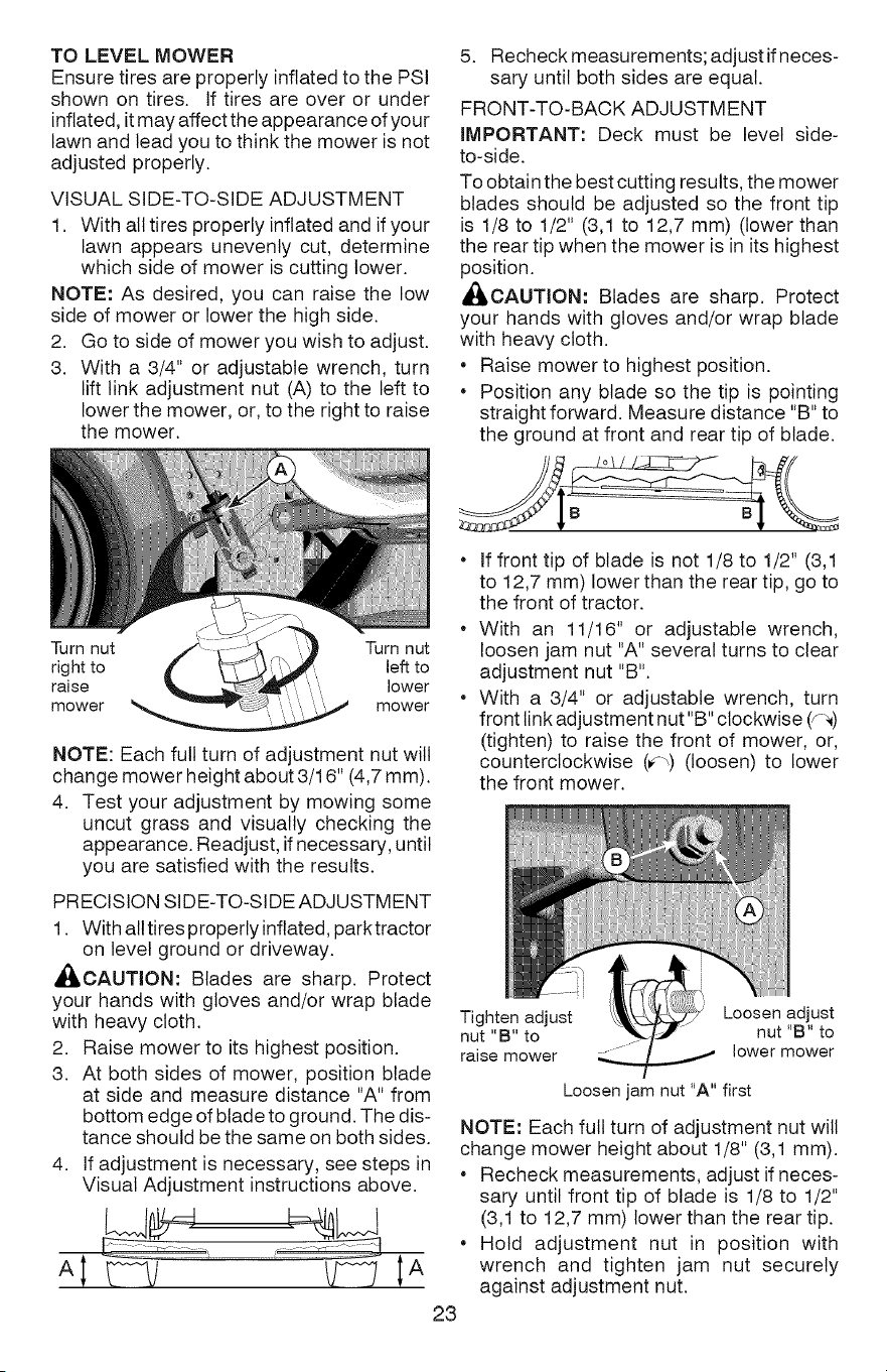
FRONT-TO-BACK ADJUSTMENT
IMPORTANT: Deck must be level side-
to-side.
To obtain the best cutting results, the mower
blades should be adjusted so the front tip
is 1/8 to 1/2" (3,1 to 12,7 mm) (lower than
the rear tip when the mower is in its highest
position.
,_CAUTION: Blades are sharp. Protect
your hands with gloves and/or wrap blade
with heavy cloth.
• Raise mower to highest position.
• Position any blade so the tip is pointing
straight forward. Measure distance "B" to
the ground at front and rear tip of blade.
Turn nut Turn nut
right to left to
raise .... lower
mower mower
NOTE: Each full turn of adjustment nut will
change mower height about 3/16" (4,7 mm).
4. Test your adjustment by mowing some
uncut grass and visually checking the
appearance. Readjust, if necessary, until
you are satisfied with the results.
PRECISION SIDE-TO-SIDE ADJUSTMENT
1. With all tires properly inflated, parktractor
on level ground or driveway.
_,CAUTION: Blades are sharp. Protect
your hands with gloves and/or wrap blade
with heavy cloth.
2. Raise mower to its highest position.
3. At both sides of mower, position blade
at side and measure distance "A" from
bottom edge of blade to ground. The dis-
tance should be the same on both sides.
4. If adjustment is necessary, see steps in
Visual Adjustment instructions above.
* If front tip of blade is not 1/8 to 1/2" (3,1
to 12,7 mm) lower than the rear tip, go to
the front of tractor.
* With an 11/16" or adjustable wrench,
loosen jam nut "A" several turns to clear
adjustment nut "B".
* With a 3/4" or adjustable wrench, turn
front link adjustment nut"B" clockwise (y-_)
(tighten) to raise the front of mower, or,
counterclockwise (_-,) (loosen) to lower
the front mower.
23
Tighten adjust Loosen adjust
nut "B" to nut "B" to
raise mower ..../ z lower mower
Loosen jam nut "A" first
NOTE: Each full turn of adjustment nut will
change mower height about 1/8" (3,1 mm).
Recheck measurements, adjust if neces-
sary until front tip of blade is 1/8 to 1/2"
(3,1 to 12,7 mm) lower than the rear tip.
Hold adjustment nut in position with
wrench and tighten jam nut securely
against adjustment nut.
TO REPLACE MOWER BLADE DRIVE
BELT
The mower blade drive belt may be replaced
without tools. Park the tractor on level sur-
face. Engage parking brake.
BELT REMOVAL -
1. Removemowerfromtractor (See"TO RE-
MOVE MOWER"inthissectionofmanual).
2. Work belt off both mandrel pulleys and
idler pulleys.
3. Putt belt away from mower.
BELT INSTALLATION -
1. Work belt around both mandrel pulleys
and idler pulleys
2. Ensure belt is in all pulley grooves and
inside all belt guides.
3. Install mower (See "To Install Mower" in
this section of this manual).
Mandrel Idler
Pulle' Pulleys
Mandrel
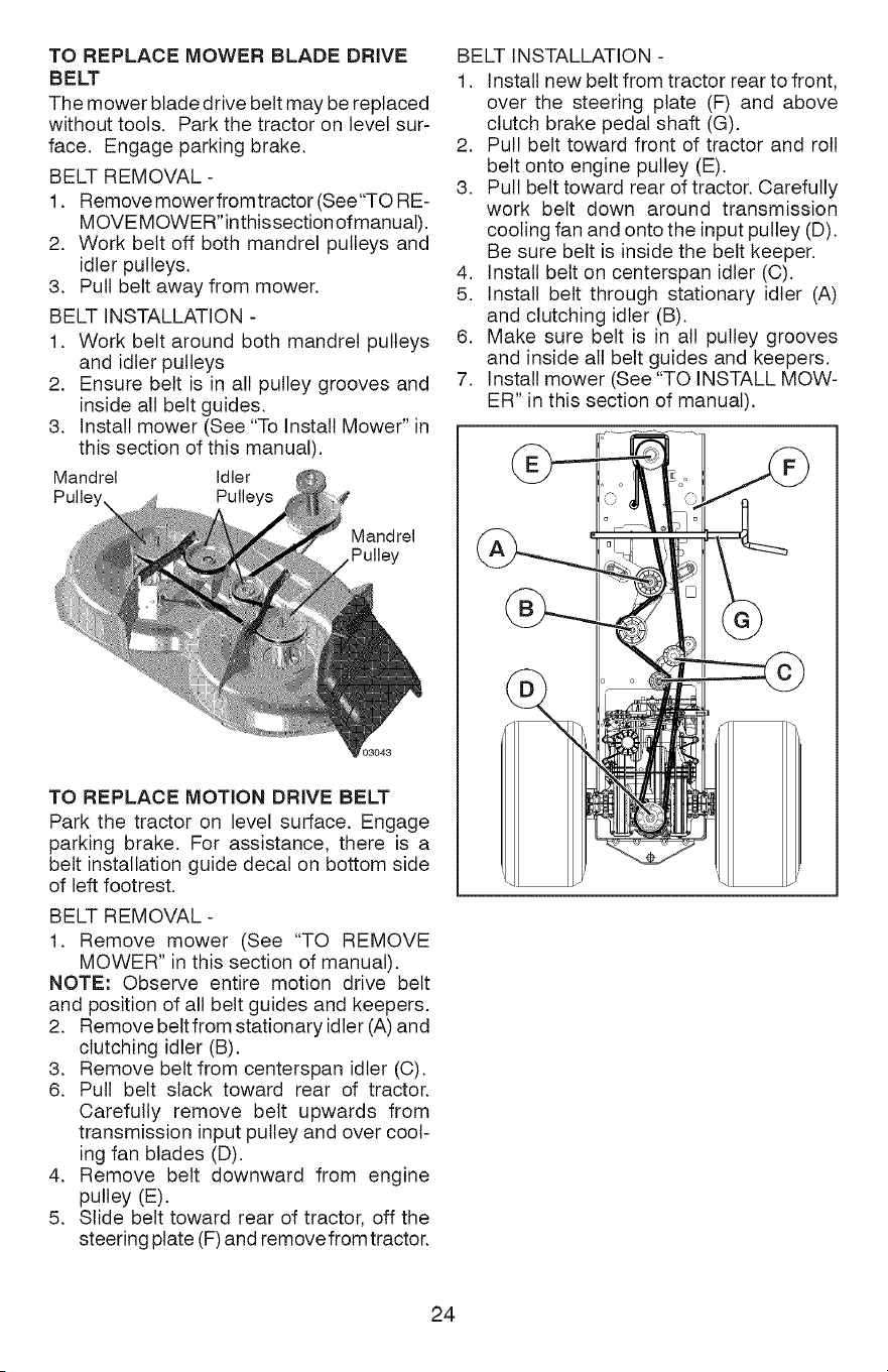
BELT INSTALLATION -
1. install new belt from tractor rear to front,
over the steering plate (F) and above
clutch brake pedal shaft (G).
2. Pull belt toward front of tractor and roll
belt onto engine pulley (E).
3. Pull belt toward rear of tractor. Carefully
work belt down around transmission
cooling fan and onto the input pulley (D).
Be sure belt is inside the belt keeper.
4. Install belt on centerspan idler (C).
5. Install belt through stationary idler (A)
and clutching idler (B).
6. Make sure belt is in all pulley grooves
and inside all belt guides and keepers.
7. Install mower (See "TO INSTALL MOW-
ER" in this section of manual).
TO REPLACE MOTION DRIVE BELT
Park the tractor on level surface. Engage
parking brake. For assistance, there is a
belt installation guide decal on bottom side
of left footrest.
BELT REMOVAL -
1. Remove mower (See "TO REMOVE
MOWER" in this section of manual).
NOTE: Observe entire motion drive belt
and position of all belt guides and keepers.
2. Remove beltfrom stationary idler (A) and
clutching idler (B).
3. Remove belt from centerspan idler (C).
6. Pull belt slack toward rear of tractor.
Carefully remove belt upwards from
transmission input pulley and over cool-
ing fan blades (D).
4. Remove belt downward from engine
pulley (E).
5. Slide belt toward rear of tractor, off the
steering plate (F) and remove from tractor.
24
TOCHECKBRAKE
If tractor requires more than five (5) feet (1,5
m) to stop at highest speed in highest gear
on a level, dry concrete or paved surface,
then brake must be serviced.
You may also check brake by:
1. Park tractor on a level, dry concrete or
paved surface, depress brake pedal all
the way down and engage parking brake.
2. Disengage transmission by placing
freewheel control in "transmission dis-
engaged" position. Pull freewheel control
out and into the slot and release so it is
held in the disengaged position.
The rear wheels must lock and skid when
you try to manually push the tractor forward.
If the rear wheels rotate, then the brake
needs to be serviced. Contact a Sears or
other qualified service center.
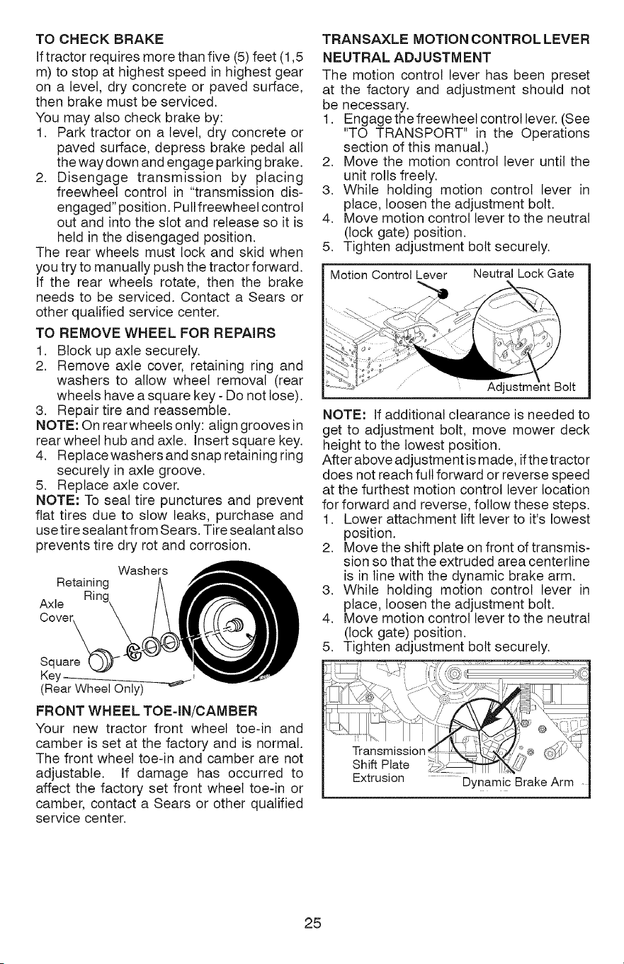
TO REMOVE WHEEL FOR REPAIRS
1. Block up axle securely.
2. Remove axle cover, retaining ring and
washers to allow wheel removal (rear
wheels have a square key - Do not lose).
3. Repair tire and reassemble.
NOTE: On rear wheels only: align grooves in
rear wheel hub and axle. Insert square key.
4. Replace washers and snap retaining ring
securely in axle groove.
5. Replace axle cover.
NOTE: To seal tire punctures and prevent
flat tires due to slow leaks, purchase and
use tire sealant from Sears. Tire sealant also
prevents tire dry rot and corrosion.
Washers
Retaining
Axle
Cover
Square
Key ____
(Rear Wheel Only)
FRONT WHEEL TOE=IN/CAMBER
Your new tractor front wheel toe-in and
camber is set at the factory and is normal.
The front wheel toe-in and camber are not
adjustable. If damage has occurred to
affect the factory set front wheel toe-in or
camber, contact a Sears or other qualified
service center.
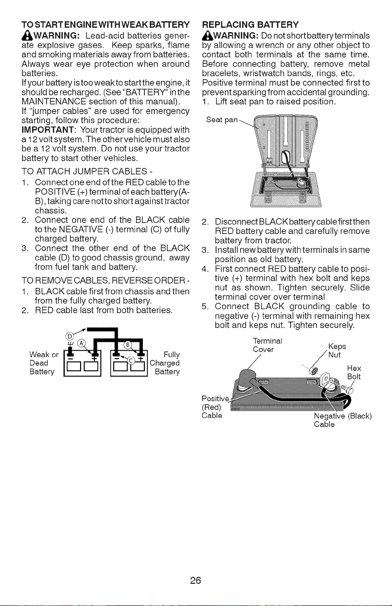
TRANSAXLE MOTION CONTROL LEVER
NEUTRAL ADJUSTMENT
The motion control lever has been preset
at the factory and adjustment should not
be necessary.
1. Engage the freewheet control lever. (See
"TO TRANSPORT" in the Operations
section of this manual.)
2. Move the motion control lever until the
unit rolls freely.
3. While holding motion control lever in
place, loosen the adjustment bolt.
4. Move motion control lever to the neutral
(lock gate) position.
5. Tighten adjustment bolt securely.
Motion Control Lever Neutral Lock Gate
Adjustm_
NOTE: If additional clearance is needed to
get to adjustment bolt, move mower deck
height to the lowest position.
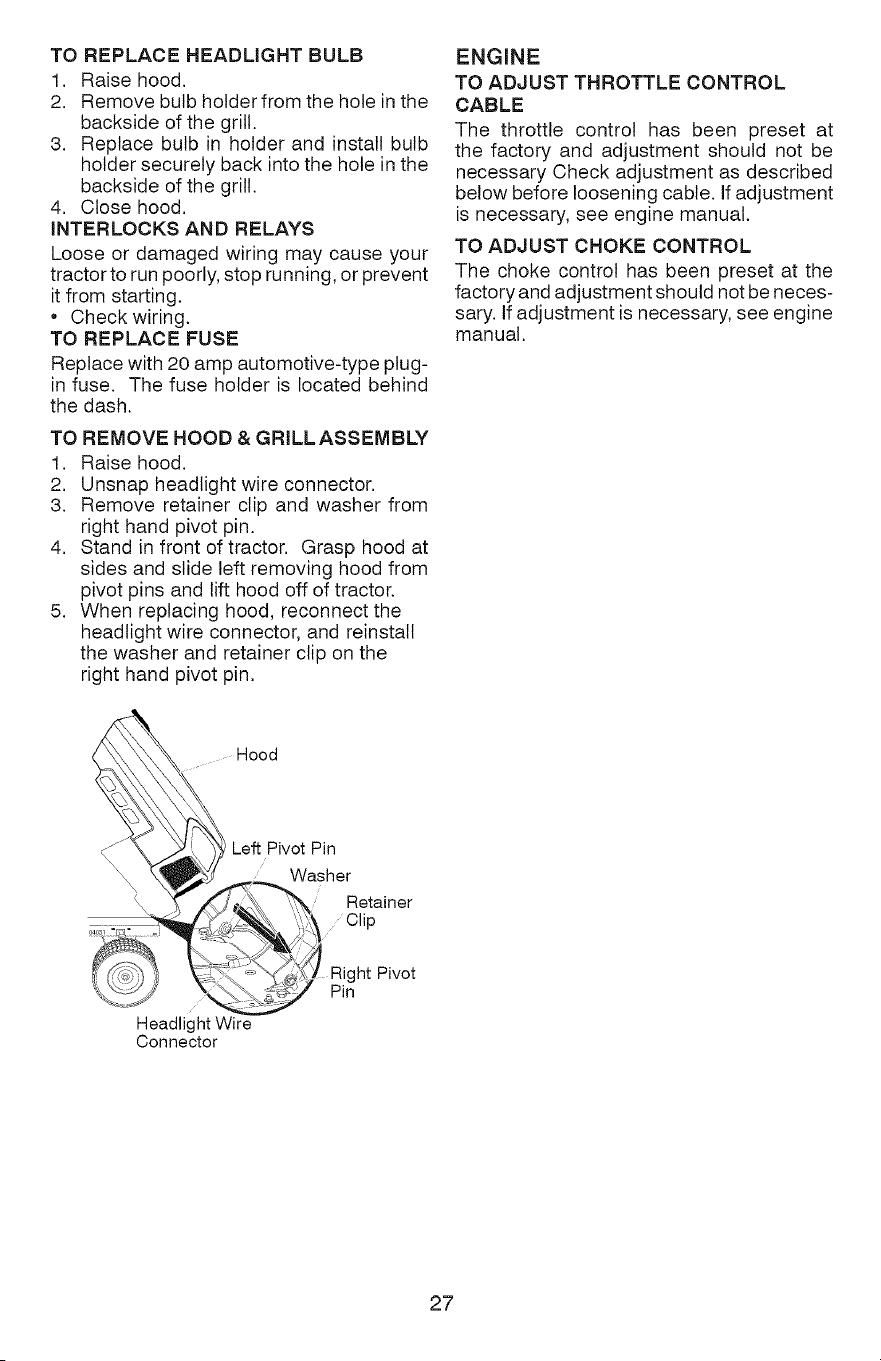
After above adjustment is made, if the tractor
does not reach full forward or reverse speed
at the furthest motion control lever location
for forward and reverse, follow these steps.
1. Lower attachment lift lever to it's lowest
position.
2. Move the shift plate on front of transmis-
sion so that the extruded area centerline
is in line with the dynamic brake arm.
3. While holding motion control lever in
place, loosen the adjustment bolt.
4. Move motion control lever to the neutral
(lock gate) position.
5. Tighten adjustment bolt securely.
Extrusion ...... DYnamic Brake Arm
25
TO START EN GIN EWITH WEAK BATTE RY
_,WARNING: Lead-acid batteries gener-
ate explosive gases. Keep sparks, flame
and smoking materials away from batteries.
Always wear eye protection when around
batteries.
Ifyour battery is too weakto start the engine, it
should be recharged. (See "BATTERY" in the
MAINTENANCE section of this manual).
If "jumper cables" are used for emergency
starting, follow this procedure:
IMPORTANT: Your tractor is equipped with
a 12 volt system. The othervehicle must also
be a 12 volt system. Do not use your tractor
battery to start other vehicles.
TO ATTACH JUMPER CABLES -
1. Connect one end of the RED cable to the
POSITIVE (+) terminal of each battery(A-
B), taking care notto short against tractor
chassis.
2. Connect one end of the BLACK cable
to the NEGATIVE (-) terminal (C) of fully
charged battery.
3. Connect the other end of the BLACK
cable (D) to good chassis ground, away
from fuel tank and battery.
TO REMOVE CABLES, REVERSE ORDER -
1. BLACK cable first from chassis and then
from the fully charged battery.
2. RED cable last from both batteries.
Weak or
Dead
Battery
Fully
Charged
Battery
REPLACING BATTERY
AI_WARNING: Do notshortbatteryterminals
by allowing a wrench or any other object to
contact both terminals at the same time.
Before connecting battery, remove metal
bracelets, wristwatch bands, rings, etc.
Positive terminal must be connected first to
prevent sparking from accidental grounding.
1. Lift seat pan to raised position.
Seat
2. Disconnect BLACK battery cabte firstthen
RED battery cable and carefully remove
battery from tractor.
3. Install new battery with terminals in same
position as old battery.
4. First connect RED battery cable to posi-
tive (+) terminal with hex bolt and keps
nut as shown. Tighten securely. Slide
terminal cover over terminal
5. Connect BLACK grounding cable to
negative (-) terminal with remaining hex
bolt and keps nut. Tighten securely.
Positive
(Red)
Cable
Terminal
Cover Keps
Nut
aex
Bolt
Negative (Black)
Cable
26
TO REPLACE HEADLIGHT BULB
1. Raise hood.
2. Remove bulb holder from the hole in the
backside of the grill.
3. Replace bulb in holder and install bulb
holder securely back into the hole in the
backside of the grill.
4. Close hood.
INTERLOCKS AND RELAYS
Loose or damaged wiring may cause your
tractor to run poorly, stop running, or prevent
it from starting.
• Check wiring.
TO REPLACE FUSE
Replace with 20 amp automotive-type plug-
in fuse. The fuse holder is located behind
the dash.
TO REMOVE HOOD & GRILLASSEMBLY
1. Raise hood.
2. Unsnap headlight wire connector.
3. Remove retainer clip and washer from
right hand pivot pin.
4. Stand in front of tractor. Grasp hood at
sides and slide left removing hood from
pivot pins and lift hood off of tractor.
5. When replacing hood, reconnect the
headlight wire connector, and reinstall
the washer and retainer clip on the
right hand pivot pin.
ENGINE
TO ADJUST THROTTLE CONTROL
CABLE
The throttle control has been preset at
the factory and adjustment should not be
necessary Check adjustment as described
below before loosening cable. If adjustment
is necessary, see engine manual.
TO ADJUST CHOKE CONTROL
The choke control has been preset at the
factory and adjustment should not be neces-
sary. If adjustment is necessary, see engine
manual.
Hood
Headlight Wire
Connector
Left Pivot Pin
Washer
Retainer
Clip
Right Pivot
Pin
27

Immediatelyprepareyourtractorforstorage
attheendoftheseasonorifthetractorwill
notbeusedfor30daysor more.
WARNING:Neverstorethetractorwith
gasolineinthetankinsidea buildingwhere
fumesmayreachanopenflameorspark.
Allowtheengineto coolbeforestoringin
anyenclosure.
TRACTOR
Removemowerfromtractorforwinterstor-
age.Whenmoweristobestoredforaperiod
oftime,cleanitthoroughly,removealldirt,
grease,leaves,etc.Storeinaclean,dryarea.
1. Cleanentiretractor(See"CLEANING"in
theMaintenancesectionofthismanual).
2. Inspectandreplacebelts,if necessary
(Seebeltreplacementinstructionsinthe
ServiceandAdjustmentssectionofthis
manual).
3. LubricateasshownintheMaintenance
sectionofthismanual.
4. Ensurethatallnuts,boltsandscrews
aresecurelyfastened.Inspectmoving
partsfordamage,breakageandwear.
Replaceifnecessary.
5. Touchupall rustedor chippedpaint
surfaces;sandlightlybeforepainting.
BATTERY
• Fullychargethebatteryforstorage.
• Aftera periodoftimeinstorage,battery
mayrequirerecharging.
• Tohelppreventcorrosionandpower
leakageduringlongperiodsofstorage,
batterycablesshouldbedisconnected
andbatterycleanedthoroughly(see"TO
CLEANBATTERYANDTERMINALS"in
theMaintenancesectionofthismanual).
• Aftercleaning,leavecablesdisconnected
andplacecableswheretheycannotcome
incontactwithbatteryterminals.
• If batteryis removedfromtractorfor
storage,donotstorebatterydirectlyon
concreteordampsurfaces.
• Ifunitisequippedwithbatteryindicator/
chargingplug,anoptionalchargingunit
maybepurchasedandconnectedtothe
unittochargethebatteryduringlongterm
storage.Inspectandcleanthebattery
terminalsasneededpriorto longterm
storagewithchargerconnected.
ENGINE
FUEL SYSTEM
IMPORTANT: It is important to prevent
gum deposits from forming in essential fuel
system parts such as carburetor, fuel hose,
ortank during storage. Also, alcohol blended
fuels (called gasohol or using ethanol or
methanol) can attract moisture which leads
to separation and formation of acids during
storage. Acidic gas can damage the fuel
system of an engine while in storage.
• Empty the fuel tank by starting the engine
and letting it run until the fuel lines and
carburetor are empty.
• Never use engine or carburetor cleaner
products in the fuel tank or permanent
damage may occur.
• Use fresh fuel next season.
NOTE: Fuel stabilizer is an acceptable al-
ternative in minimizing the formation of fuel
gum deposits during storage. Add stabilizer
to gasoline in fuel tank or storage container.
Always follow the mix ratio found on stabilizer
container. Run engine at least 10 minutes
after adding stabilizer to allow the stabilizer to
reach the carburetor. Do not empty the gas
tank and carburetor if using fuel stabilizer.
ENGINE OiL
Drain oil (with engine warm) and replace
with clean engine oil. (See "ENGINE" in the
Maintenance section of this manual).
CYLINDER(S)
1. Remove spark plug(s).
2. Pour one ounce (29.5 mL) of oil through
spark plug hole(s) into cylinder(s).
3. Turn ignition key to "START" position for
a few seconds to distribute oil.
4. Replace with new spark plug(s).
OTHER
• Do not store gasoline from one season to
another.
• Replace your gasoline can ifyour can starts
to rust. Rust and/or dirt in your gasoline
wilt cause problems.
• If possible, store your tractor indoors and
cover itto give protection from dust and dirt.
• Cover your tractor with a suitable protec-
tive cover that does not retain moisture.
Do not use plastic. Plastic cannot breathe
which allows condensation to form and will
cause your tractor to rust.
IMPORTANT: Never cover tractor while
engine and exhaust areas are still warm.
28
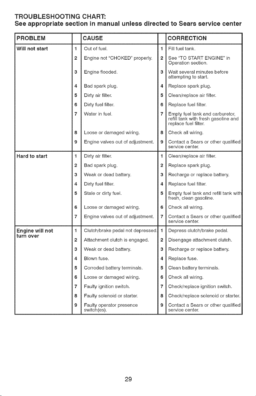
TROUBLESHOOTING CHART:
See appropriate section in manual unless directed to Sears service center
PROBLEM CAUSE CORRECTION
Will not start 1 Out of fuel. 1 Fill fuel tank.
2 Engine not "CHOKED" properly, 2 See "TO START ENGINE" in
Operation section,
3 Engine flooded. 3 Wait several minutes before
attempting to start,
4 Bad spark plug. 4 Replace spark plug.
5 Dirty air filter. 5 Clean/replace air filter,
6 Dirty fuel filter, 6 Replace fuel filter.
7 Water in fuel. 7 Empty fuel tank and carburetor,
refill tank with fresh gasoline and
replace fuel filter.
8 Loose or damaged wiring, 8 Check all wiring,
9 Engine valves out of adjustment, 9 Contact a Sears or other qualified
service center
Hard to start 1 Dirty air filter. 1 Clean/replace air filter.
2 Bad spark plug. 2 Replace spark plug.
3 Weak or dead battery, 3 Recharge or replace battery,
4 Dirty fuel filter, 4 Replace fuel filter.
5 Stale or dirty fuel. 5 Empty fuel tank and refill tank wig-
fresh, clean gasoline.
6 Loose or damaged wiring, 6 Check all wiring,
7 Engine valves out of adjustment, 7 Contact a Sears or other qualified
service center
Engine will not 1 Clutch/brake pedal not depressed 1 Depress clutch/brake pedal.
turn over
2 Attachment clutch is engaged. 2 Disengage attachment clutch.
3 Weak or dead battery. 3 Recharge or replace battery.
4 Blown fuse. 4 Replace fuse.
5 Corroded battery terminals. 5 Clean battery terminals.
6 Loose or damaged wiring. 6 Check all wiring.
7 Faulty ignition switch. 7 Check/replace ignition switch.
8 Faulty solenoid or starter. 8 Check/replace solenoid or starter.
9 Faulty operator presence 9 Contact a Sears or other qualified
switch(es), service center.
29
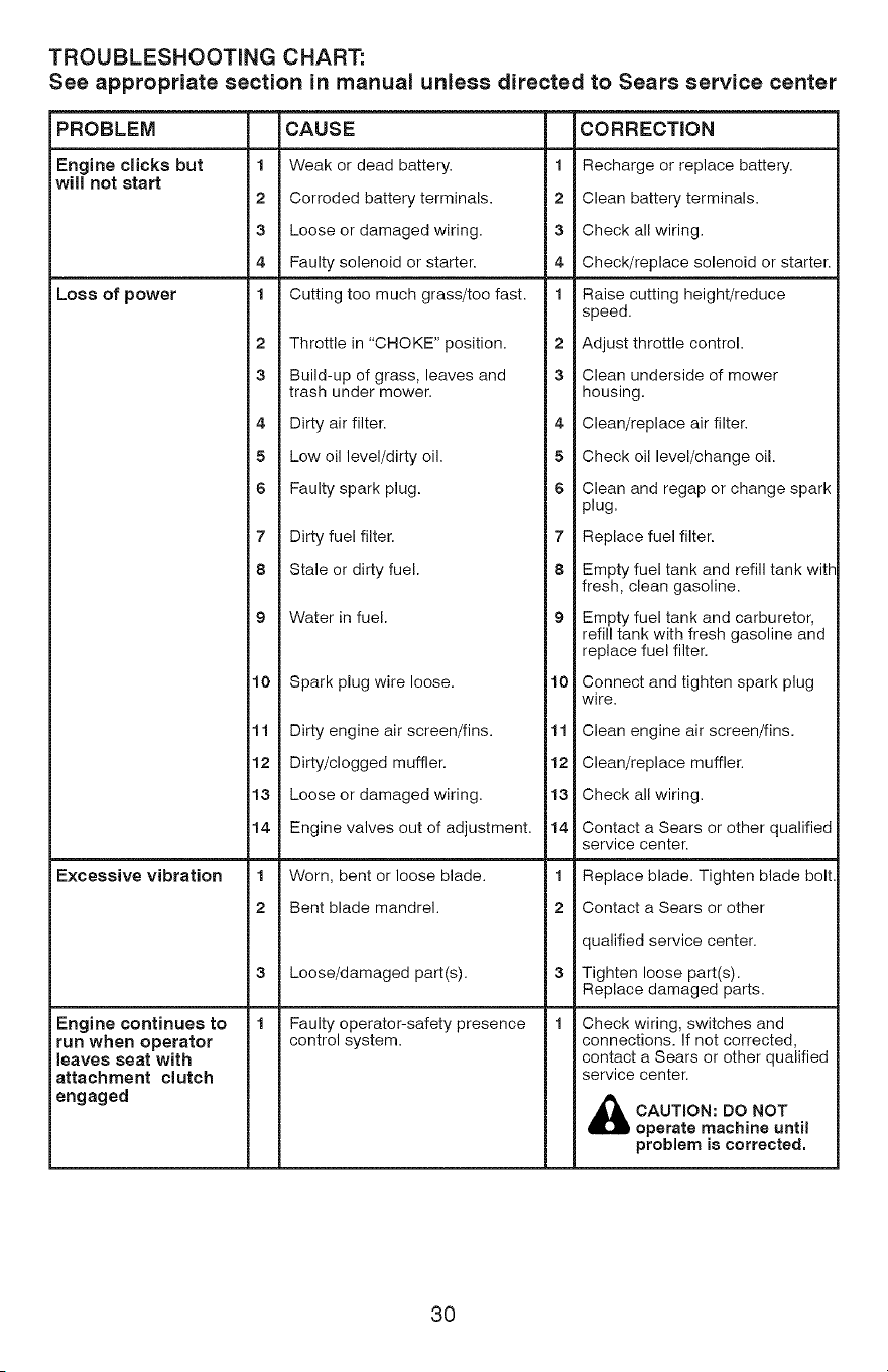
TROUBLESHOOTING CHART:
See appropriate section in manual unless directed to Sears service center
PROBLEM
Engine clicks but
wiJJnot start
Loss of power
Excessive vibration
1
2
3
4
1
2
3
CAUSE
Weak or dead battery.
Corroded battery terminals.
Loose or damaged wiring.
Faulty solenoid or starter.
Cutting too much grass/too fast.
Throttle in "CHOKE" position.
Build-up of grass, leaves and
trash under mower.
4 Dirty air filter.
5 Low oil level/dirty oil.
6 Faulty spark plug.
7 Dirty fuel filter.
8 Stale or dirty fuel.
9 Water in fuel.
10 Spark plug wire loose.
11
12
13
14
1
2
Dirty engine air screen/fins.
Dirty/clogged muffler.
Loose or damaged wiring.
Engine valves out of adjustment.
Worn, bent or loose blade.
Bent blade mandrel.
Loose/damaged part(s).
Faulty operator-safety presence
control system.
Engine continues to
run when operator
Jeaves seat with
attachment cJutch
engaged
CORRECTION
1 Recharge or replace battery.
2 Clean battery terminals.
3 Check all wiring.
4 Check/replace solenoid or starter.
1 Raise cutting height/reduce
speed.
2 Adjust throttle control.
3 Clean underside of mower
housing.
4 Clean/replace air filter.
5 Check oil level/change oil.
6 Clean and regap or change spark
plug.
7 Replace fuel filter.
8 Empty fuel tank and refill tank with
fresh, clean gasoline.
9 Empty fuel tank and carburetor,
refill tank with fresh gasoline and
replace fuel filter.
10 Connect and tighten spark plug
wire.
11 Clean engine air screen/fins.
12 Clean/replace muffler.
13 Check all wiring.
14 Contact a Sears or other qualified
service center.
1 Replace blade. Tighten blade bolt.
2 Contact a Sears or other
qualified service center.
3 Tighten loose part(s).
Replace damaged parts.
1 Check wiring, switches and
connections. If not corrected,
contact a Sears or other qualified
service center.
_b CAUTmON: DO NOT
operate machine until
problem is corrected.
30
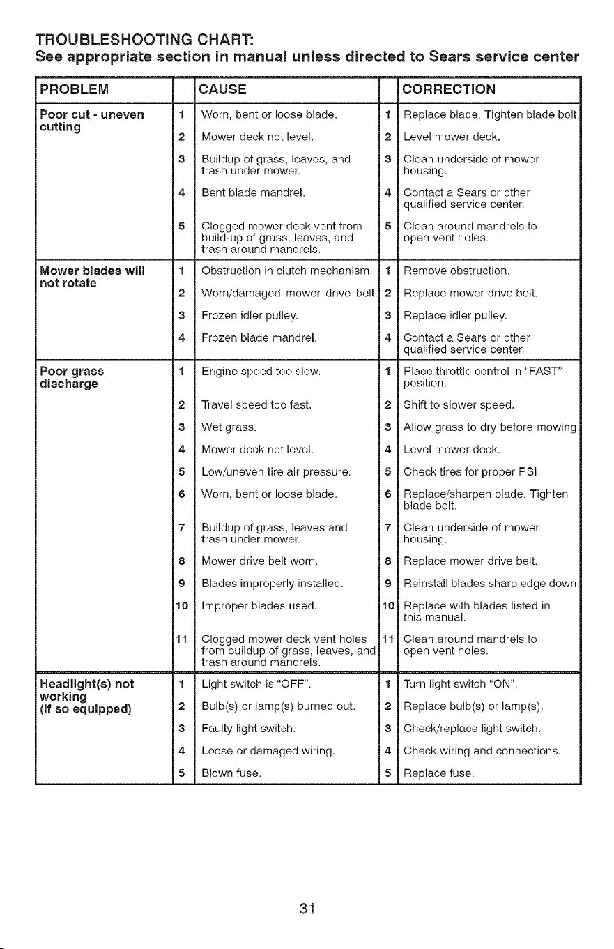
TROUBLESHOOTING CHART:
See appropriate section in manual unless directed to Sears service center
PROBLEM
Poor cut = uneven
cutting
Mower blades will
not rotate
Poor grass
discharge
Headlight(s) not
working
(if so equipped)
CAUSE
1 Worn, bent or loose blade. 1
2 Mower deck not level. 2
3 Buildup of grass, leaves, and 3
trash under mower.
4 Bent blade mandrel. 4
!5 Clogged mower deck vent from
build-up of grass, leaves, and
trash around mandrels.
1 Obstruction in clutch mechanism.
2 Worn/damaged mower drive belt
3 Frozen idler pulley.
4 Frozen blade mandrel.
1 Engine speed too slow.
2 Travel speed too fast.
3 Wet grass.
4 Mower deck not level.
5 Low/uneven tire air pressure.
6 Worn, bent or loose blade.
7 Buildup of grass, leaves and
trash under mower.
8 Mower drive belt worn.
9 Blades improperly installed.
10 Improper blades used.
11 Clogged mower deck vent holes
from buildup of grass, leaves, and
trash around mandrels.
1 Light switch is "OFF".
2 Bulb(s) or lamp(s) burned out.
3 Faulty light switch.
4 Loose or damaged wiring.
5 Blown fuse.
CORRECTION
Replace blade. Tighten blade bolt
Level mower deck.
Clean underside of mower
housing.
Contact a Sears or other
qualified service center.
Clean around mandrels to
open vent holes.
1 Remove obstruction.
2 Replace mower drive belt.
3 Replace idler pulley.
4 Contact a Sears or other
qualified service center.
1 Place throttle control in "FAST"
position.
2 Shift to slower speed.
3 Allow grass to dry before mowing
4 Level mower deck.
5 Check tires for proper PSI.
6 Replace/sharpen blade. Tighten
blade bolt.
7 Clean underside of mower
housing.
8 Replace mower drive belt.
9 Reinstall blades sharp edge down
10 Replace with blades listed in
this manual.
11 Clean around mandrels to
open vent holes.
1 Turn light switch "ON".
2 Replace bulb(s) or lamp(s).
3 Check/replace light switch.
4 Check wiring and connections.
5 Replace fuse.
31

TROUBLESHOOTING CHART:
See appropriate section in manual unless directed to Sears service center
PROBLEM
Battery will not
charge
Loss of drive
Engine "backfires"
when turning
engine "OFF"
Engine dies when
tractor is shifted
into reverse
1
2
3
4
1
CAUSE CORRECTION
Bad battery cell(s). 1 Replace battery.
Poor cable connections. 2 Check/clean all connections.
Faulty regulator (if so equipped). 3 Replace regulator.
Faulty alternator. 4 Replace alternator.
Freewheel control in 1 Place freewheel control in
"DISENGAGED" position. "ENGAGED" position.
Debris on steering plate (if 2 See "CLEANING" in the
I equipped), maintenance section.
Motion drive belt worn, damaged, 3 Replace motion drive belt.
or broken.
I Axle key missing. 4 Install axle key at rear wheel. See
"TO REMOVE WHEEL" in the
Service and Adjustments section.
Move throttle control between
half and full speed (fast) position
before stopping engine.
Engine throttle control not sel 1
between half and full speed (fast)
position before stopping engine.
Reverse operation system (ROS) 1
is not "ON" while mower or other
attachment is engaged.
Turn ignition key to ROS "ON"
position. See Operation section.
32
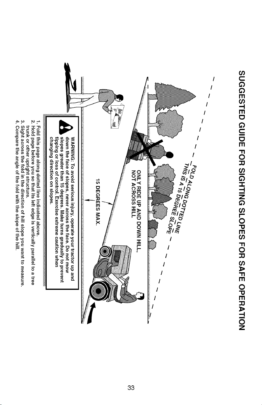
SUGGESTED GUIDE FOR SIGHTING SLOPES FOR SAFE OPERATION
ONLY RIDE UP AND DOWN HILL,
NOT ACROSS HILL
15 DEGREES MAX.
_ ARNING: To avoid serious injury, operate your tractor up and
down the face of slopes, never across the face. Do not mow
slopes greater than 15 degrees. Make turns gradually to prevent
tipping or loss of control. Exercise extreme caution when
changing direction on slopes.
1. Fold this page along dotted line indicated above.
2. Hold page before you so that its left edge is vertically parallel to a tree
trunk or other upright structure.
3. Sight across the fold in the direction of hill slope you want to measure.
4. Compare the angle of the fold with the slope of the hill.
03
03
Garantia .......................................................... 34 Programa de Mantenimiento .......................... 48
Reglas de Seguridad ...................................... 35 Servicio y Ajustes ........................................... 53
Especificaciones del Producto ........................ 38 Almacenamiento ............................................. 60
Montaje/Pre Operaci6n ................................... 39 Identificaci6n de Problemas ........................... 61
Operaci6n ....................................................... 41 Servicio Sears .................................. Contratapa
Mantenimiento ................................................ 48
GarantJa para equJpos tractores Craftsman
GARANTIA COMPLETA DE CRAFTSMAN
POR DOS AI_JOS desde la fecha de compra, todas las partes no sustituibles de este equipo tractor estan
garantizadas contra cualquier defecto de material o mano de obra. Una parte no sustituible defectuosa
recibira reparaci6n o reemplazo gratuito en casa si la reparaci6n es imposible.
POR CINCO AI_IOS desde la fecha de compra, el bastidor y el eje delantero de este equipo tractor estan
garantizados contra cualquier defecto de material o mano de obra. Un bastidor o eje delantero defectuoso
recibira reparaci6n o reemplazo gratuito en casa si la reparaci6n es imposible.
DURANTE 90 DiAS desde la fecha de compra, la bateria (una parte sustituible) de este equipo tractor
esta_ garantizada contra cualquier defecto de material o mano de obra (nuestra prueba comprueba que no
contendra carga). Una bateria defectuosa recibir_, un reemplazo gratuito en casa.
GARANTiA LJMITADA DE POR VIDA ADICIONAL en el EJE DELANTERO DE HERRO COLADO (8i
esta provisto)
DURANTE EL TIEMPO EN QUE SE USE por el propietario original despues del quinto argo a partir de la
fecha de compra, el eje delantero de hierro colado (si estb_ provisto) de este equipo tractos estb_ garantizado
contra cualquier defecto de material o mano de obra. Con el comprobante de compra, un eje delantero de
hierro colado recibir_, un reemplazo gratuito en casa.
SERVIClO DE GARANTiA
Para conocer los detalles de la cobertura de garantia para obtener una reparaci6n o reemplazo gratuito,
Ilame al 1-800-659-5917 6 visite el sitio web: www. craftsman.com
En todos los casos anteriores, si el reemplazo es imposible, el equipo tractor ser_. sustituido sin cargo con
el mismo modelo o uno equivalente.
Toda la cobertura de garantia anterior serb_ nula si este equipo tractor se utiliza alguna vez para brindar
servicios comerciales o si se alquila a otra persona.
Esta garantia cubre 0 NICAM ENTE defectos de material y mano de obra. La cobertura de garantia NO incluye:
• Partes sustituibles (excepto la bateria) que se puedan desgastar por el uso normal dentro del periodo de
garantia incluso, pero sin limitarse a, cuchillas, bujias, filtros de aire, correas y filtros de aceite.
• Servicios de mantenimiento estandar, cambios de aceite o afinaciones.
• Reemplazo o reparaci6n de neum_.ticos por pinchazos causados por objetos externos como clavos,
espinas, tocones o vidrios.
• Reemplazo o reparaci6n de neumaticos o ruedas por desgaste normal, accidentes o por operaci6n o
mantenimiento incorrectos.
• Reparaciones necesarias por abuso del operador incluso, pero sin limitarse a, dafios causados por
remolcar objetos que superen la capacidad del equipo tractor, chocar contra objetos que doblen el
bastidor, el ensamble del eje o el cigOe_al o sobrepasar la velocidad del motor.
• Reparaciones necesarias por negligencia del operador, incluso (pero sin limitarse a ello) da_os electricos
y mecanicos causados por el almacenamiento incorrecto, por no usar el grado y la cantidad correctos de
aceite de motor, por no mantener del muelle libre de residuos inflamables o por no mantener el equipo
tractor de acuerdo con las instrucciones que contiene el manual del operador.
• Limpieza o reparaciones del motor (sistema de combustible) cuando se determina que se us6
combustible contaminado y oxidado (sarro). En general, el combustible debe usarse dentro de los 30
dias posteriores a su compra.
• Deterioro y desgaste normal de los acabados exteriores o sustituci6n de r6tulos de productos.
Esta garantia le otorga derechos legales especificos, y usted tambi&n puede tener otros derechos que
varian de un estado a otro.
Sears Brands Management Corporation, Hoffman Estates, JL 60179
34
_PELIGRO: Esta Maquina cortadora es capaz de amputar las manosy los pies y de lanzar
objetos, si no se observan las instrucciones de seguridad siguientes se pueden producir
Jesiones graves o Ja muerte.
_ADVERTENCIA: Siempre desconecte el alam-
bre de la bujia y p6ngalo donde no pueda entrar
en contacto con la bujia, para evitar el arranque
por acciciente, durante la preparaci6n, el trans-
porte, el ajuste o cuando se hacen reparaciones.
_DVERTENOIA: No avance cuesta abajo a pu n-
to muerto ya que podria perder el control del tractor.
_bADVERTENCIA: Remolque solamente los
accesorios recomendados y conformes a las
caracteristicas indicadas por el fabricante de su
tractor. Tenga cuidacio y prudencia al utilizar el
tractor. Cuando se encuentre en un declive, oper
utilizando exclusivamente la velocidad ma.sbaja.
En caso de un declive una carga excesiva po-
dria resultar peligrosa. Los neum&ticos pueden
perder la tracci6n con el suelo y hacerle perder
el control de su tractor.
_ADVERTENCIA: El tubo de escape del motor,
algunos de sus constituyentes y algunos com-
)onentes del vehiculo contienen o desprenden
productos quimicos conocidos en el Estado de
California como causa de ca.ncer y defectos al
nacimiento u otros daSos reproductivos.
_DVERTENCIA: Los bomes, terminales y ac-
cesorios relativos de la bateria contienen plomo
o compuestos de plomo, productos quimicos
conocidos en el Estado de California como causa
de c&ncer y defectos al nacimiento u otros daSos
reproductivos. Lavar Jas manos despues de
manipularlos,
FUNCIONAMIENTO GENERAL
Leer, entender y seguir todas las instrucciones
sobre la m&quina y en el manual antes de
empezar.
No poner las manos o los pies cerca de partes
giratorias o debajo de la m&quina, mantener
siempre limpia la abertura de descarga.
Permitir el funcionamiento de la m&quina s61o
a adultos que tengan familiaridad con las
instrucciones.
Limpiar el &rea de objetos como piedras,
juguetes, cables, etc. que pueden ser recogi-
dos y disparados con las cuchillas.
Asegurarse de que el &rea este libre de otras
personas antes de ponerla en marcha. Parar
la m_.quina si alguien entra en el &tea.
Nunca Ilevar pasajeros.
No cortar marcha atr&s al no ser absolu-
tamente necesario. Mirar siempre abajo y
delante mientras se procede atr&s.
Nunca dirigir el material descargado hacia na-
die. Evitar descargar material contra paredes
u obstrucciones. El material podria rebotar
hacia el operador. Parar las cuchillas cuando
se pasan superficies de grava.
35
• No maneje la m&quina si no tiene la trampa
para cesped completa, la canaleta de descarga
u otros dispositivos de seguridad en su lugar
y en funcionamiento.
• Ralentizar antes de girar.
• Nunca dejar una m&quina encendida sin vigi-
lancia. Apagar siempre las cuchillas, poner el
freno de estacionamiento, parar el motor, y
quitar las Ilaves antes de bajar.
• Desenganche las hojas cuando no este cortan-
do cesped. Apague el motor y espere hasta que
todas las partes se detengan por completo an-
tes de limpiar la m&quina, retirar la trampa para
cesped o destapar la canaleta de descarga.
Hacer funcionar la m&quina s61o con la luz del
dia o luz artificial buena.
No hacer funcionar la m&quina estando bajo
los efectos de alcohol o droga.
Porter atenci6n al tr&fico cuando se opera
cerca de calles o se cruzan.
Porter la m&xima atenci6n al cargar o descar-
gar la m&quina en una caravana o cami6n.
Llevar siempre gafas de protecci6n cuando se
hace funcionar la m&quina.
Use protectores de oidos para evitar daSos en
la audici6n.
Los datos indican que los operadores a partir
de los 60 aSos est&n afectados por un gran
porcentaje de heridas relativas a la conducci6n
del cortacesped. Estos operadores tendrian
que evaluar su habilidad de hacer funcionar
el cortacesped de modo Io bastante seguro
para proteger a si mismos y a otras personas
de heridas graves.
• Seguir las recomendaciones del fabricante
para los pesos y contrapesos de las ruedas.
• Mantener la m&quina libre de hierba, hojas u
otros escombros que pueden tocar el tubo de
escape/partes del motor calientes y quemarse.
No permitir que el puente del cortacesped
cargue hojas u otros residuos que pueden
causar acumulaciones. Limpiar toda salpica-
dura de aceite o carburante antes de hacer
operaciones sobre la m&quina o guardarla.
Dejarla enfriar antes de guardarla.
II. FUNCiONAMIENTO EN PENDIENTES
Las pendientes son el mayor factor de accidentes
relativos a la p@dida de control y vuelco, que
pueden causar severas heridas o muerte. El fun-
cionamiento en pendientes requiere una atenci6n
extra. Si no es posible hacer marcha atr&s en una
pendiente o si te sientes incomodo, no la cortes.
• Cortar hacia arriba y abajo de una pendiente,
no de modo horizontal.
• Poner atenciones a los hoyos, las raices, los
bultos, las piedras u otros objetos escondidos.
El terreno irregular puede volcar la m&quina.
La hierba alta puede esconder obst&culos.
• Escoger una velocidad de marcha baja de
modo que no sea necesario pararse o cambiar
estando en una pendiente.
• No cortar la hierba mojada. Las ruedas pueden
perder tracci6n.
Poner siempre una marcha cuando se esta
en pendientes. No poner en punto muerto e ir
cuesta abajo.
• Evitar arrancar, pararse o girar en una pendien-
te. Si las ruedas pierden tracci6n, desconectar
las cuchillas y proceder despacio cuesta abajo
en la pendiente.
• Mantener todo los movimientos en las pen-
dientes lentos y gradual. No hacer cambios
repentinos de velocidad o direcci6n, ya que
pueden causar el escape de la m_.quina.
•Poner la ma.xima atenci6n cuando la maquina
funciona con captadores de hierba u otros
dispositivos enganchados; pueden afectar la
estabilidad de la maquina. No usar en pendi-
entes empinados.
• No intentar estabilizar la maquina poniendo el
pie en el terreno.
• No cortar cerca de bajadas, cunetas y orillas.
Las maquina puede volcarse improvisamente
si una rueda esta en el borde o se hunde.
o
o
m,NINOS
_,ADVERTENOIA: LOS NINOS PUEDEN
SUFRIR DANOS CON EL USO DE ESTE EQUI-
PO. La Academia Estadounidense de Pediatria
(American Academy of Pediatrics) recomienda
que s61o se permita a ni_os con una edad mini-
ma de 12 aSos manejar maquinas cortacesped
manuales, y al menos de 16 a_os para manejar
tractores cortacesped.
Si el operador no pone atenci6n a la presencia
de los niSos pueden ocurrir accidentes tr&gicos.
Los niSos a menudo esta.n atraidos por la m&qui-
na y las actividad de cortar. No dar por hecho
de que los niSos se queden adonde estaban la
Qltima vez que los vistes.
• Mantener los niSos fuera del &rea de corte y •
vigilados por un adulto responsable que no sea
el operador.
• Estar alerta y apagar la m&quina si un ni_os
entra en el area.
• Antes y durante la marcha atras, mirar adelante
y abajo para ver si hay ni_os peque_os.
• Nunca Ilevar ni_os, incluso si hay las cuchillas
apagadas. Podrian caer y herirse seriamente
o interferir con el funcionamiento seguro de la "
maquina, los ni_os que se han Ilevado prec-
edentemente pueden aparecer de pronto en el •
area de corte por otro paseo y ser atropellados
o tumbados por la maquina.
36
Nunca dejar que los ni_os manipulen la ma-
quina.
Tener el maximo cuidado cuando se acerca
a cantos ciegos, arbustos, arboles u otros
objetos que pueden impedir la vista de ni_os.
iV, REMOLQUE
• Remolcar s61ocon una m&quina que tenga un
gancho diseSado para remolcar. Enganchar el
equipo o remolcar s61o en el punto dispuesto
al efecto.
• Seguir las recomendaciones del productor con
respecto a los limites del equipo por remolcar
y el remolque en pendientes.
• Nunca permitir que niSos u otras personas
esten dentro del equipo por remolcar.
• En pendientes, el peso del equipo remolcado
puede causar la perdida de tracci6n y la per-
dida de control.
• Viajar despacio y dejar m&s distancia para
frenar.
V. SERViClO
MANIPULACION SEGURA DE LA GASOLINA
Para evitar heridas personales o da_os alas
cosas, poner el m&ximo cuidado a la hora de
manipular la gasolina. La gasolina es extrema-
mente inflamable y los vapores son explosivos.
• Apagar todos los cigarrillos, cigarros, pipas y
otras fuentes de ignici6n.
• Usar s61o contenedores para gasolina aproba-
dos.
• Nunca quitar el tap6n de la gasolina o a_adir car-
burante con el motor en marcha, dejar enfriar el
motor antes del abastecimiento de la gasolina.
• Nunca abastecer la m&quina al interior de un
local.
• Nunca guardar la m&quina o el contenedor
del carburante donde haya una llama abierta,
chispas o una luz piloto como un calentador
de agua u otros dispositivos.
• Nunca Ilenar los contenedores al interior de
un vehiculo o en una caravana o cami6n
recubiertos con un forro de pl&stico. Colocar
siempre los contenedores en el terreno lejos
del vehiculo cuando se est& Ilenando.
Quitar el equipo de gas del cami6n o caravana
y abastecerlo en el terreno. Si no es posible,
abastecer dicho equipo con un contenedor por-
t&til, m&s bien que de un surtidor de gasolina.
Mantener la boquilla a contacto del borde
del dep6sito de carburante o la abertura del
contenedor durante toda la operaci6n de
abastecimiento. No utilizar un dispositivo con
boquilla cerrada-abierta.
Si se vierte carburante sobre la ropa, cambi-
arse la ropa inmediatamente.
Nunca Ilenar el dep6sito m&s de Io debido.
Volver a colocar el tap6n del gas y cerrar de
modo firme.
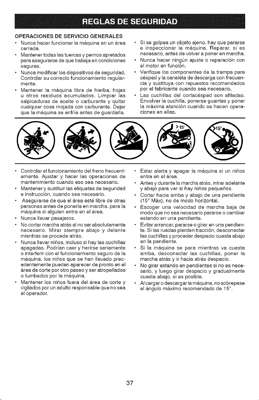
OPERACIONES DE SERVICIO GENERALES
• Nunca hacer funcionar la m&quina en un &rea
cerrada.
• Mantener todas las tuercas y pemos apretados
para asegurarse de que trabaja en condiciones
seguras.
• Nunca modificar los dispositivos de seguridad.
Controlar su correcto funcionamiento regular-
mente.
• Mantener la m&quina libre de hierba, hojas
u otros residuos acumulados. Limpiar las
salpicaduras de aceite o carburante y quitar
cualquier cosa mojada con carburante. Dejar
que la m&quina se enfrJe antes de guardarla.
• Si se golpea un objeto ajeno, hay que pararse
e inspeccionar la ma.quina. Reparar, si es
necesario, antes de volver a poner en marcha.
• Nunca hacer ningt_n ajuste o reparaci6n con
el motor en funci6n.
• Verifique los componentes de la trampa para
cesped y la canaleta de descarga con frecuen-
ciay sustituya con repuestos recomendados
por el fabricante cuando sea necesario.
• Las cuchillas del cortacesped son afiladas.
Envolver la cuchilla, ponerse guantes y poner
la ma.xima atenci6n cuando se hacen opera-
ciones en elias.
Controlar el funcionamiento del freno frecuent-
emente. Ajustar y hacer las operaciones de
mantenimiento cuando eso sea necesario.
Mantener y sustituir las etiquetas de seguridad
e instrucci6n, cuando sea necesario.
Asegurarse de que el &rea este libre de otras
personas antes de ponerla en marcha, para la
m&quina si alguien entra en el &tea.
Nunca Ilevar pasajeros.
No cortar marcha atr&s al no ser absolutamente
necesario. Mirar siempre abajo y delante
mientras se procede atr&s.
Nunca Ilevar niSos, incluso si hay las cuchillas
apagadas. PodrJan caer y herirse seriamente
o interferir con el funcionamiento seguro de la
m&quina, los niSos que se han Ilevado prec-
edentemente pueden aparecer de pronto en el
&rea de corte por otro paseo y ser atropellados
o tumbados por la m&quina.
Mantener los niSos fuera del &rea de corte y
vigilados por un adulto responsable que no sea
el operador.
• Estar alerta y apagar la m&quina si un niSos
entra en el &rea.
• Antes y durante la marcha atra.s, mirar adelante
y abajo para ver si hay niSos pequeSos.
• Cortar hacia arriba y abajo de una pendiente
(15 ° Ma.x), no de modo horizontal.
• Escoger una velocidad de marcha baja de
modo que no sea necesario pararse o cambiar
estando en una pendiente.
• Evitar arrancar, pararse o girar en una pendien-
te. Si las ruedas pierden tracci6n, desconectar
las cuchillas y proceder despacio cuesta abajo
en la pendiente.
• Si la m&quina se para mientras va cuesta
arriba, desconectar las cuchillas, poner la
marcha atr&s y ir hacia atr&s despacio.
• No girar estando en pendientes si no es nece-
sario, y luego girar despacio y gradualmente
cuesta abajo, si es posible.
• AI cargar o descargar la m&quina, no sobrepase
el &ngulo m&ximo recomendado de 15°.
37
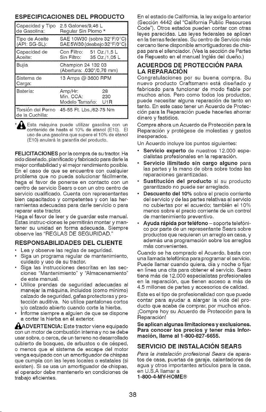
ESPECIFICACIONESDELPRODUCTO
Capacidad y Tipo 2.5 Galones/9,46 L
de Gasolina: Regular Sin PIomo *
Tipo de Aceite SAE 10W30 (sobre 32°F/0°C)
(API: SG-SL): SAE 5W30 (deabajo 32° F/0°C)
Capacidad de Con Filtro: 51 Oz./1,5 L
Aceite: Sin Filtro: 35 Oz./1,05 L
Bujia Champion 24 132 03
(Abertura: .030"/0,76 mm)
Sistema de 13 Amps @ 3600 RPM
Carga:
Bateria: Amp/Hr: 28
Min. CCA: 230
Modelo Tamafio: U1R
Torsi6n del Perno 45-55 Ft. Lbs./62-75 Nm
de la Cuchilla:
/%
*,_. Esta mAquina puede utilizar gasolina con un
contenido de hasta el 10% de etanol (El0). El
uso de una gasolina que supere el 10% de etanol
(El0) anular& la garantia del producto.
FELICITACIONES por la compra de su tractor. Ha
sido diseSado, planificado y fabricado para darle la
mejor confiabilidad y el mejor rendimiento posible.
En el caso de que se encuentre con cualquier
problema que no pueda solucionar f&cilmente,
haga el favor de ponerse en contacto con un
centro de servicio Sears o con un otro centro de
servicio cualificado. Cuenta con representantes
bien capacitados y competentes y con las her-
ramientas adecuadas para darle servicio o para
reparar este tractor.
Haga el favor de leer y de guardar este manual.
Estas instruc-ciones le permitir&n montar y man-
tener su unidad en forma adecuada. Siempre
observe las "REGLAS DE SEGURIDAD."
RESPONSABILIDADES DEL CLIENTE
• Lea y observe las reglas de seguridad.
• Siga un programa regular de mantenimiento,
cuidado y uso de su tractor.
• Siga las instrucciones descritas en las sec-
clones "Mantenimiento" y 'Almacenamiento"
de este manual.
• Utilice prendas de seguridad adecuadas al
manejar la m&quina, incluidos (como minimo)
calzado de seguridad, gafas protectoras y pro-
tecci6n auditiva. No utilice pantalones cortos
y/o calzado abierto cuando corte la hierba.
• Informe siempre a alguien de que se dispone
a cortar la hierba en el exterior.
_ADVERTENCIA: Este tractor viene equipado
con un motor de combusti6n interna y no se debe
usar sobre, o cerca, de un terreno no desarrollado
cubierto de bosques, de arbustos o de cesped,
o menos que el sistema de escape del motor
venga equipado con un amortiguador de chispas
que cumpla con las leyes locales o estatales (si
existen). Si se usa un amortiguador de chispas,
el operador debe mantenerlo en condiciones de
trabajo eficientes.
En el estado de California, la ley exige Io anterior
(Secci6n 4442 del "California Public Resources
Code"). Otros estados pueden contar con otras
leyes parecidas. Las leyes federales se aplican
en la tierras federales. Su centro de Servicio m&s
cercano tiene disponible amortiguadores de chis-
pas para el silenciador. (Vea la secci6n de Partes
de Repuesto en el manual Ingles del dueSo.)
ACUERDOS DE PROTECCION PARA
LA REPARACION
Congratulaciones por su buena compra. Su
nuevo producto Craftsman,; est& diseSado y
fabricado para funcionar de modo fiable por
muchos aSos. Pero como todos los productos,
puede necesitar alguna reparaci6n de tanto en
tanto. En este caso tener un Acuerdo de Protec-
ci6n para la Reparaci6n puede hacerles ahorrar
dinero y fastidios.
Compre ahora un Acuerdo de Protecci6n para la
Reparaci6n y protegese de molestias y gastos
inesperados.
Un Acuerdo incluye los puntos siguientes:
• Servieio expetto de nuestros 12.000 espe-
cialistas profesionales en la reparaci6n.
• Servieio ilimitado sin cargo alguno para
las partes y la mano de obra sobre todas las
reparaciones garantizadas.
• Sustitueion del produeto si su producto
garantizado no puede ser arreglado.
• Deseuento de110% sobre el precio corriente
del servicio y de las partes relativas al servicio
no cubiertas por el acuerdo; tambien el 10%
menos sobre el precio corriente de un control
de mantenimiento preventivo.
• Ayuda rapida pot telefono- soporte telef6ni-
co por parte de un representante Sears sobre
productos que requieren un arreglo en casa, y
ademas una programaci6n sobre los arreglos
mas convenientes.
Cuando se ha comprado el Acuerdo, basta con
una Ilamada telef6nica para programar el servicio.
Puede Ilamar cuando quiera, dia y noche o fijar
en linea una cita para obtener el servicio. Sears
tiene mas de 12.000 especialistas profesionales
en la reparaci6n, que tienen acceso a mas de
4.5 millones de partes y accesorios de calidad.
Este es el tipo de profesionalidad con que puede
contar para ayudar a alargar la vida del pro-
ducto que acaba de comprar, por muchos aSos.
iCompre hoy su Acuerdo de Protecci6n para la
Reparaci6n!
Se aplican algunas limitaciones y exclusiones.
Pata conocer Ice ptecios y tenet mas Infot-
maci6n, llame al 1-800-827-6655.
SERVICIO DE INSTALACION SEARS
Para la instalaciSn profesional Sears de apara-
tos de casa, puertas de garaje, calentadores de
agua y otros importantes articulos para la casa,
en U.S.A Ilamar a
1-800-4-MY-HOME®
38
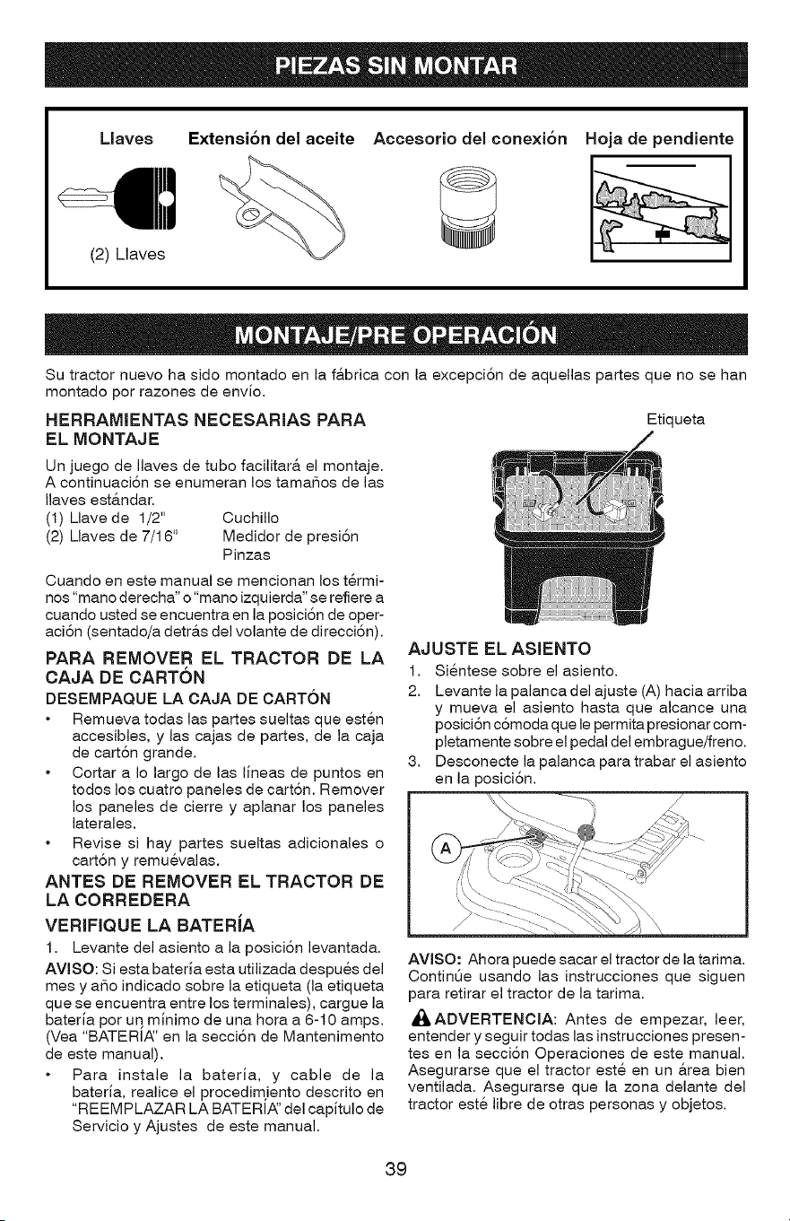
Llaves Extensi6n del aceite Hoja de pendiente
(2) Llaves
Accesorio del conexi6n
Su tractor nuevo ha sido montado en la fabrica con la excepci6n de aquellas partes que no se han
montado por razones de envio.
HERRAMIENTAS NECESARIAS PARA
EL MONTAJE
Etiqueta
Un juego de Ilaves de tubo facilitar& el montaje.
A continuaci6n se enumeran los tamafios de las
Ilaves est&ndar.
(I) Llave de 1/2' Cuchillo
(2) Llaves de 7/16' Medidor de presi6n
Pinzas
Cuando en este manual se mencionan los t@mi-
nos "mano derecha" o "mano izquierda" se refiere a
cuando usted se encuentra en la posici6n de oper-
aci6n (sentado/a detr&s del volante de direcci6n).
PARA REMOVER EL TRACTOR DE LA
CAJA DE CARTON
DESEMPAQUE LA OAJA DE CARTON
Remueva todas las partes sueltas que esten
accesibles, y las cajas de partes, de la caja
de cart6n grande.
Cortar a Io largo de las lineas de puntos en
todos los cuatro paneles de cart6n. Remover
los paneles de cierre y aplanar los paneles
laterales.
Revise si hay partes sueltas adicionales o
cart6n y remuevalas.
ANTES DE REMOVER EL TRACTOR DE
LA CORREDERA
VERIFIQUE LA BATERJA
1. Levante del asiento a la posici6n levantada.
AVlSO: Siesta bateria esta utilizada despues del
mes y afio indicado sobre la etiqueta (la etiqueta
que se encuentra entre los terminales), cargue la
bateria por uq minimo de una hora a 6-10 amps.
(Vea "BATERI,_' en la secci6n de Mantenimento
de este manual).
Para instale la bateria, y cable de la
bateria, realice el procedimjento descrito en
"REEM PLAZAR LA BATERIA_'del capitulo de
Servicio y Ajustes de este manual.
AJUSTE EL ASIENTO
1. Sientese sobre el asiento.
2. Levante la palanca del ajuste (A) hacia arriba
y mueva el asiento hasta que alcance una
posici6n c6moda que le permita presionar com-
pletamente sobre el pedal del embrague/freno.
3. Desconecte la palanca para trabar el asiento
en la posici6n.
AVISO: Ahora puede sacar el tractor de la tarima.
ContinQe usando las instrucciones que siguen
para retirar el tractor de la tarima.
_ADVERTENOIA: Antes de empezar, leer,
entender y seguir todas las instrucciones presen-
tes en la secci6n Operaciones de este manual.
Asegurarse que el tractor este en un &tea bien
ventilada. Asegurarse que la zona delante del
tractor este libre de otras personas y objetos.
39
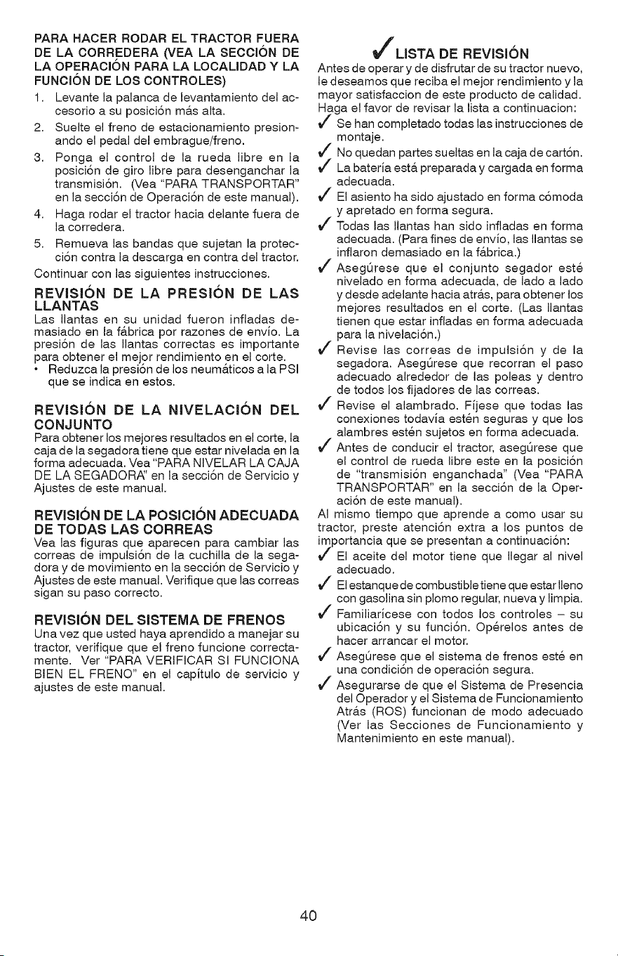
PARA HACER RODAR EL TRACTOR FUERA
DE LA CORREDERA (VEA LA SECCION DE
LA OPERACI6N PARA LA LOCALIDAD Y LA
FUNCI6N DE LOS CONTROLES)
1. Levante la palanca de levantamiento del ac-
cesorio a su posici6n m&s alta.
2. Suelte el freno de estacionamiento presion-
ando el pedal del embrague/freno.
3. Ponga el control de la rueda libre en la
posici6n de giro libre para desenganchar la
transmisi6n. (Vea "PARA TRANSPORTAR"
en la secci6n de Operaci6n de este manual).
4. Haga rodar el tractor hacia delante fuera de
la corredera.
5. Remueva las bandas que sujetan la protec-
ci6n contra la descarga en contra del tractor.
Continuar con las siguientes instrucciones.
REVJSI6N DE LA PRESK)N DE LAS
LLANTAS
Las Ilantas en su unidad fueron infladas de-
masiado en la f&brica por razones de envio. La
presi6n de las Ilantas correctas es importante
para obtener el mejor rendimiento en el corte.
• Reduzca la presi6n de los neum&ticos a la PSI
que se indica en estos.
REVISION DE LA NIVELACION DEL
CONJUNTO
Para obtener los mejores resultados en el corte, la
caja de la segadora tiene que estar nivelada en la
forma adecuada. Vea "PARA NIVELAR LA CAJA
DE LA SEGADOR,_' en la secci6n de Servicio y
Ajustes de este manual.
REVJSJ6N DE LA POSICION ADECUADA
DE TODAS LAS CORREAS
Yea las figuras que aparecen para cambiar las
correas de impulsi6n de la cuchilla de la sega-
dora y de movimiento en la secci6n de Servicio y
Ajustes de este manual. Verifique que las correas
sigan su paso correcto.
REVISION DEL SISTEMA DE FRENOS
Una vez que usted haya aprendido a manejar su
tractor, verifique que el freno funcione correcta-
mente. Ver "PARA VERIFICAR SI FUNCIONA
BIEN EL FRENO" en el capitulo de servicio y
ajustes de este manual.
I_'LISTA DE REVISION
Antes de operar y de disfrutar de su tractor nuevo,
le deseamos que reciba el mejor rendimiento y la
mayor satisfaccion de este producto de calidad.
Haga el favor de revisar la lista a continuacion:
Se hart completado todas las instrucciones de
montaje.
No quedan partes sueltas en la caja de cart6n.
La bateria est& preparada y cargada en forma
adecuada.
El asiento ha sido ajustado en forma c6moda
y apretado en forma segura.
Todas las Ilantas hart sido infladas en forma
adecuada. (Para fines de envio, las Ilantas se
inflaron demasiado en la f&brica.)
Asegt_rese que el conjunto segador este
nivelado en forma adecuada, de lado a lado
y desde adelante hacia atr&s, para obtener los
mejores resultados en el corte. (Las Ilantas
tienen que estar infladas en forma adecuada
para la nivelaci6n.)
Revise las correas de impulsi6n y de la
segadora. AsegSrese que recorran el paso
adecuado alrededor de las poleas y dentro
de todos los fijadores de las correas.
Revise el alambrado. Fijese que todas las
conexiones todavia esten seguras y que los
alambres esten sujetos en forma adecuada.
Antes de conducir el tractor, aseg@ese que
el control de rueda libre este en la posici6n
de "transmisi6n enganchada" (Vea "PARA
TRANSPORTAR" en la secci6n de la Oper-
aci6n de este manual).
AI mismo tiempo que aprende a como usar su
tractor, preste atenci6n extra a los puntos de
importancia que se presentan a continuaci6n:
El aceite del motor tiene que Ilegar al nivel
adecuado.
Elestanque de combustibletiene que estar Ileno
con gasolina sin plomo regular, nueva y limpia.
Familiaricese con todos los controles - su
ubicaci6n y su funci6n. Op@elos antes de
hacer arrancar el motor.
AsegQrese que el sistema de frenos este en
una condici6n de operaci6n segura.
Asegurarse de que el Sistema de Presencia
del Operador y el Sistema de Funcionamiento
Atra.s (ROS) funcionan de modo adecuado
(Ver las Secciones de Funcionamiento y
Mantenimiento en este manual).
40
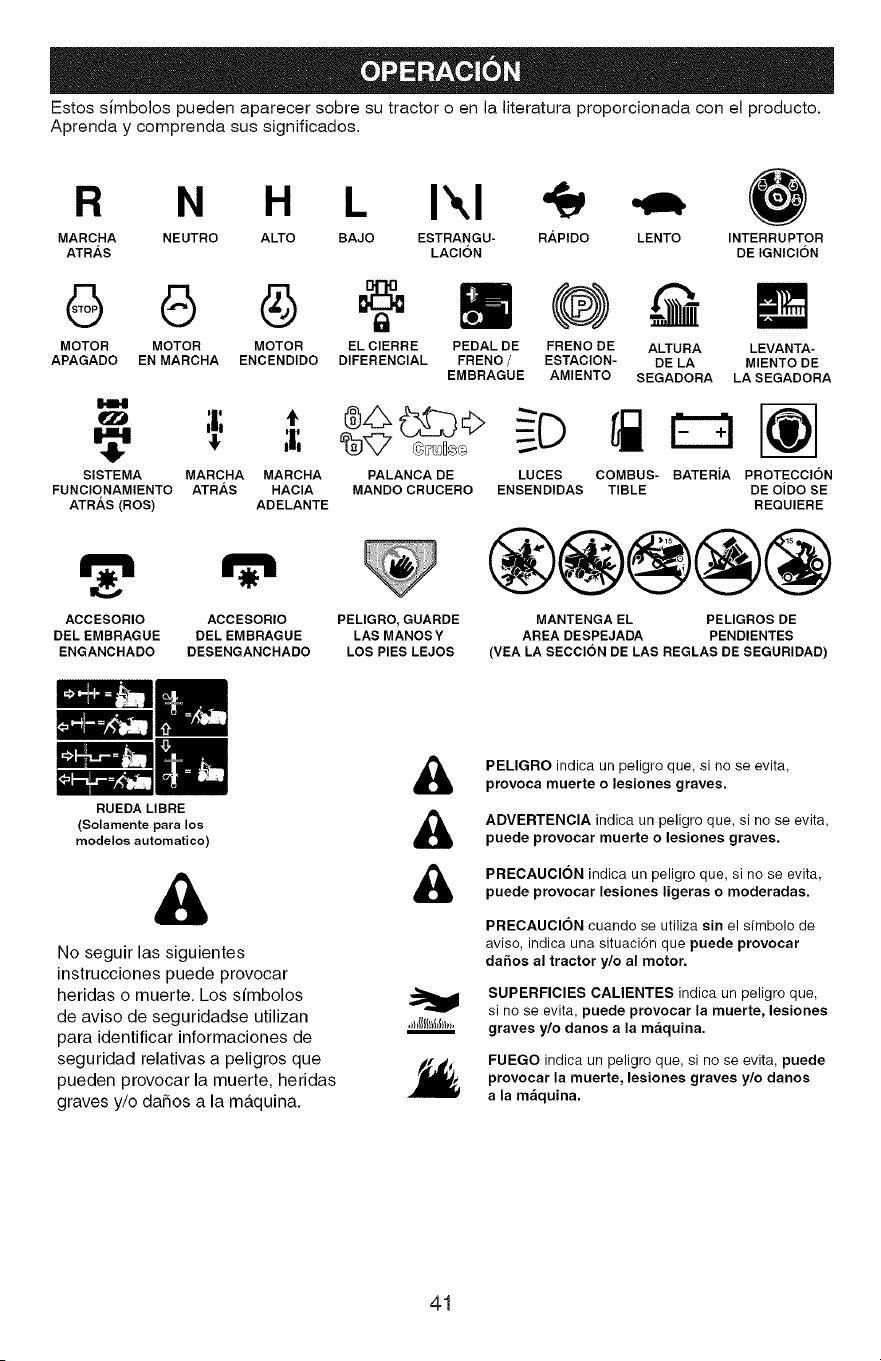
Estos simbolos pueden aparecer sobre su tractor o en la literatura proporcionada con el producto.
Aprenda y comprenda sus significados.
R N H L I\1
MARCHA NEUTRO ALTO BAJO ESTRANGU- RAPIDO
ATR/_S LACION
6 G
MOTOR MOTOR MOTOR
APAGADO EN MARCHA ENCENDIDO
SISTEMA MARCHA MARCHA
FUNCIONAMIENTO ATR/_S HACIA
ATRAS (ROS) ADELANTE
EL ClERRE PEDAL DE
DIFERENCIAL FRENO /
EMBRAGUE
FRENO DE
ESTACION-
AMIENTO
PALANCA DE LUCES
MANDO CRUCERO ENSENDIDAS
LENTO INTERRUPTER
DE IGNICI6N
ACCESORIO ACCESORIO PELIGRO, GUARDE
DEL EMBRAGUE DEL EMBRAGUE LAS MANOSY
ENGANCHADO DESENGANCHADO LOS PIES LEJOS
ALTURA
DE LA
SEGADORA
LEVANTA-
MIENTO DE
LASEGADORA
COMBUS- BATERiA PROTECCION
TIBLE DE OiDO SE
REQUIERE
®@@@@
MANTENGA EL PELIGROS DE
AREA DESPEJADA PENDIENTES
(VEA LA SECCION DE LAS REGLAS DE SEGURIDAD)
RUEDA LIBRE
(Solamente para los
modelos automatico)
&
No seguir las siguientes
instrucciones puede provocar
heridas o muerte, Los simbolos
de aviso de seguridadse utilizan
para identificar informaciones de
seguridad relativas a peligros que
pueden provocar la muerte, heridas
graves y/o daSos a la maquina,
&
&
&
m
PELIGRO indica un peligro que, si no se evita,
provoca muerte o lesiones graves.
ADVERTENCIA indica un peligro que, si no se evita,
puede provocar muerte o lesiones graves.
PRECAUCION indica un peligro que, si no se evita,
puede provocar lesiones ligeras o moderadas.
PRECAUCION cuando se utiliza sin el sfmbolo de
aviso, indica una situaci6n que puede provocar
da5os al tractor y/o al motor.
SUPERFICIES CALIENTES indica un peligro que,
si no se evita, puede provocar la muerte, lesiones
graves y/o danos a la maquina.
FUEGO indica un peligro que, si no se evita, puede
provocar la muerte, lesiones graves y/o danos
a la maquina.
41
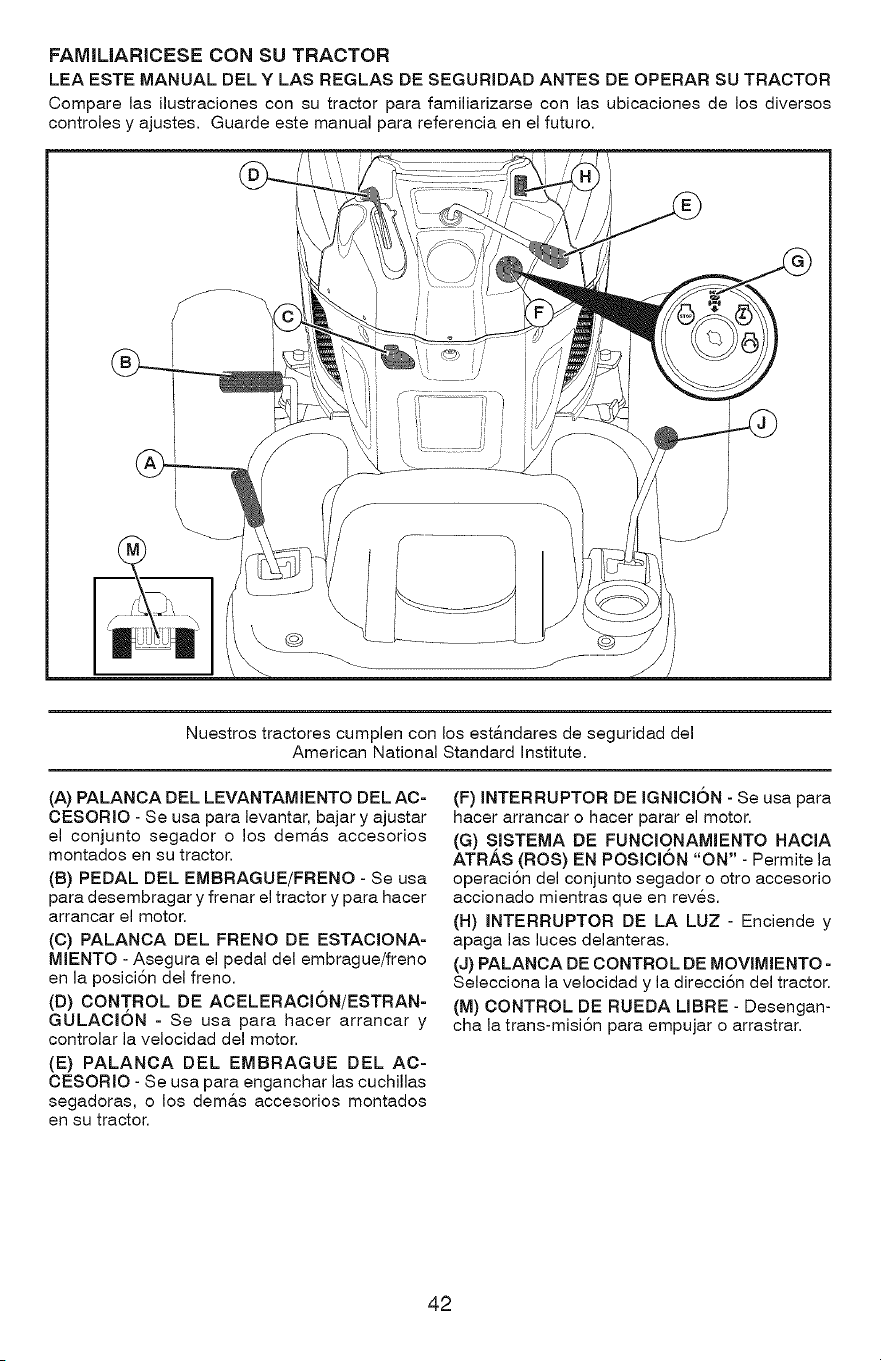
FAMIMARICESE CON SU TRACTOR
LEA ESTE MANUAL DEL Y LAS REGLAS DE SEGURIDAD ANTES DE OPERAR SU TRACTOR
Compare las ilustraciones con su tractor para familiarizarse con las ubicaciones de los diversos
controles y ajustes. Guarde este manual para referencia en el futuro.
\
Nuestros tractores cumplen con los est&ndares de seguridad del
American National Standard institute.
(A) PALANCA DEL LEVANTAMIENTO DEL AC-
CESORIO - Se usa para levantar, bajar y ajustar
el conjunto segador o los dem&s accesorios
montados en su tractor.
(B) PEDAL DEL EMBRAGUE/FRENO - Se usa
para desembragar y frenar el tractor y para hacer
arrancar el motor.
(C) PALANCA DEL FRENO DE ESTACIONA-
MIENTO - Asegura el pedal del embrague/freno
en la posici6n del freno.
(D) CONTROL DE ACELERACION/ESTRAN-
GULACION - Se usa para hacer arrancar y
controlar la velocidad del motor.
(E) PALANCA DEL EMBRAGUE DEL AC-
CESORIO - Se usa para enganchar las cuchillas
segadoras, o los dem&s accesorios montados
en su tractor.
(F) INTERRUPTOR DE IGNICION - Se usa para
hacer arrancar o hacer parar el motor.
(G) SISTEMA DE FUNCIONAMaENTO HACIA
ATR.&S (ROS) EN POSICION "ON" - Permite la
operaci6n del conjunto segador o otro accesorio
accionado mientras que en reves.
(H) INTERRUPTOR DE LA LUZ - Enciende y
apaga las luces delanteras.
(J) PALANCA DE CONTROL DE MOVIMIENTO -
Selecciona la velocidad y la direcci6n del tractor.
(M) CONTROL DE RUEDA LIBRE - Desengan-
cha la trans-misi6n para empujar o arrastrar.
42
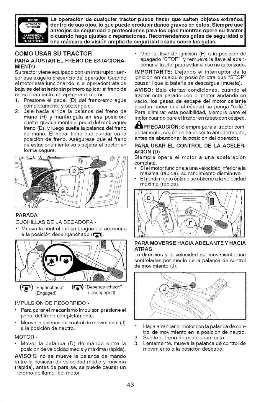
_" __stos. Siernpre use |
anteojoa d_ntraa opere au tractor |
gafas de seguridad o |
una mascara de viai6n arnplia de aeguridad uaada sobre laa gafaa.
COMO USAR SU TRACTOR
PARA AJUSTAR EL FRENO DE ESTACIONA-
MIENTO
Su tractor viene equipado con un interruptor sen-
sor que exige la presencia del operador. Cuando
el motor est& funcionando, si el operador trata de
bajarse del asiento sin primero aplicar el freno de
estacionamiento, se apagara, el motor.
1. Presione el pedal (D) del freno/embrague
completamente y sostengalo.
2. Jale hacia arriba la palanca del freno de
mano (H) y mantengala en esa posici6n;
suelte gradualmente el pedal del embrague/
freno (D), y luego suelte la palanca del freno
de mano. El pedal tiene que quedar en la
posici6n de freno. AsegQrese que el freno
de estacionamiento va a sujetar el tractor en
forma segura.
PARADA
CUCHILLAS DE LA SEGADORA -
• Mueva la control del embrague del accesorio
a la posici6n desenganchado (1"_1).
• Gire la Ilave de igniciSn (F) a la posiciSn de
apagado "STOP" y remueva la Ilave al aban-
donar el tractor para evitar el uso no autorizado.
IMPORTANTE: Dejando el interruptor de la
igniciSn en cualquier posiciSn otra que "STOP"
causar i que la bateria se descargue (muerta).
AVlSO: Bajo ciertas condiciones, cuando el
tractor est& parado con el motor andando en
vacio, los gases de escape del motor caliente
pueden hacer que el cesped se ponga "cafe."
Para eliminar esta posibilidad, siempre pare el
motor cuando pare el tractor en &reas con cesped.
_IIPRECAUCI6N: Siempre pare el tractor com-
pletamente, seg5n se ha descrito anteriormente,
antes de abandonar la posici6n del operador.
PARA USAR EL CONTROL DE LA ACELER-
ACION (D)
Siempre opere el motor a una aceleraciSn
completa.
• Si el motor funciona a una velocidad inferior a la
m&xima (r&pida), su rendimiento disminuye.
• El rendimiento 5ptimo se obtiene a la velocidad
m&xima (r&pida).
PARA MOVERSE HACIA ADELANTE Y HACIA
ATRAS
La direcci6n y la velocidad del movimiento son
controladas por medio de la palanca de control
de movimiento (J).
(r_l) "Enganchado" (1"_1) "Desenganchado"
(Engaged) (Disengaged)
IMPULSI6N DE RECORRIDO -
• Para parar el mecanismo impulsor, presione el
pedal del freno completamente.
• Mueva la palanca de control de movimiento (J)
a la posici6n de neutro.
MOTOR -
• Mover la palanca (D) de mando entre la
posici6n de velocidad media y m&xima (r&pida).
AVISO:Si no se mueve la palanca de mando
entre la posiciSn de velocidad media y m&xima
(r&pida), antes de pararse, se puede causar un
"retorno de llama" del motor.
1. Haga arrancar el motor con la palanca de con-
trol de movimiento en la posiciSn de neutro.
2. Suelte el freno de estacionamiento.
3. Lentamente, mueva la palanca de control de
movimiento a la posici6n deseada.
43
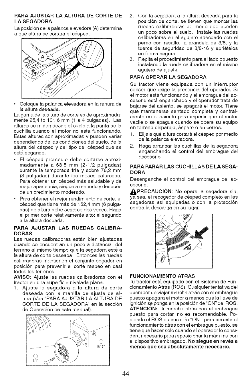
PARA AJUSTAR LA ALTURA DE CORTE DE
LA SEGADORA
La posiciSn de la palanca elevadora (A) determina
a que altura se cortar& el cesped.
• Coloque la palanca elevadora en la ranura de
la altura deseada.
La gama de la altura de corte es de aproximada-
mente 25,4 to 101,6 mm (1 a 4 pulgadas). Las
alturas se miden desde el suelo a la punta de la
cuchilla cuando el motor no est& funcionando.
Estas alturas son aproximadas y pueden variar
dependiendo de las condiciones del suelo, de la
altura del cesped y del tipo del cesped que se
est& segando.
• El cesped promedio debe cortarse aproxi-
madamente a 63,5 mm (2-1/2 pulgadas)
durante la temporada fria y sobre 76,2 mm
(3 pulgadas) durante los meses calurosos.
Para obtener un cesped m&s saludable y de
mejor apariencia, siegue a menudo y despues
de un crecimiento moderado.
• Para obtener el mejor rendimiento de corte, el
cesped que tiene m&s de 152,4 mm (6 pulga-
das) de altura debe segarse dos veces. Haga
el primer corte relativamente alto; el segundo
a la altura deseada.
PARA AJUSTAR LAS RUEDAS CALIBRA-
DORAS
Las ruedas calibradoras est&n bien ajustadas
cuando se encuentran un poco a distancia del
terreno al mismo tiempo que la segadora este a
la altura de corte deseada. Entonces las ruedas
calibradoras mantienen el conjunto segador en
posiciSn para prevenir el corte raspeo en casi
todos los terrenos.
AVlSO: Ajuste las ruedas calibradoras con el
tractor en una superficie nivelada plana.
1. Ajuste la segadora a la altura de corte
deseada con la manilla de ajuste de al-
tura (Vea "PARA AJUSTAR LA ALTURA DE
CORTE DE LA SEGADORA_' en la secciSn
de OperaciSn de este manual).
2. Con la segadora a la altura deseada para la
posici6n de corte, se tienen que montar las
ruedas calibradoras de modo que queden
un poco sobre el suelo. Instale las ruedas
calibradoras en el agujero adecuado con el
perno con resalto, la arandela de 3/8, y la
tuerca de seguridad de 3/8-16 y aprietelos
en forma segura.
3. Repita el procedimiento para el lado opuesto
instalando la rueda calibradora en el mismo
agujero de ajuste.
PARA OPERAR LA SEGADORA
Su tractor viene equipada con un interruptor
sensor que exige la presencia del operador. Si
el motor est& funcionando y el embrague del ac-
cesorio est& enganchado y el operador trata de
bajarse del asiento, se apagar& el motor. Tiene
que mantenerse sentado completa y central-
mente en el asiento para impedir que el motor
vacile o se apague cuando se opere su equipo
en terreno disparejo, &spero o en cerros.
1. Elija a que altura cortar& el cesped por medio
de la palanca elevadora.
2. Haga arrancar las cuchillas de la segadora
enganchando el control del embrague del
accesorio.
PARA PARAR LAS CUCHILLAS DE LA SEGA-
DORA
Desenganche el control del embrague del ac-
cesorio.
_PREOAUOI6N: No opere la segadora sin,
ya sea, el recogedor de cesped completo en las
segadoras asi equipadas o con la protecciSn
contra la descarga en su lugar.
FUNCIONAMIENTO ATRAS
Tu tractor est& equipado con el Sistema de Fun-
cionamiento Atra.s (ROS). Cualquier tentativa del
operador de viajar marcha atra.s con el embrague
puesto apagara, el motor a menos que la Ilave de
igniciSn se ponga en la posiciSn de "ON" del ROS.
ATENCION: Ir marcha atr&s con el embrague
puesto para cortar, no es recomendable. Po-
niendo el ROSen posiciSn "ON", para permitir el
funcionamiento atr&s con el embrague puesto, se
tiene que hacer s61o cuando el operador Io consi-
dera necesario para reposicionar la m&quina con
el dispositivo embragado. No siegue en revesa
menos que sea absolutarnente necesario.
44
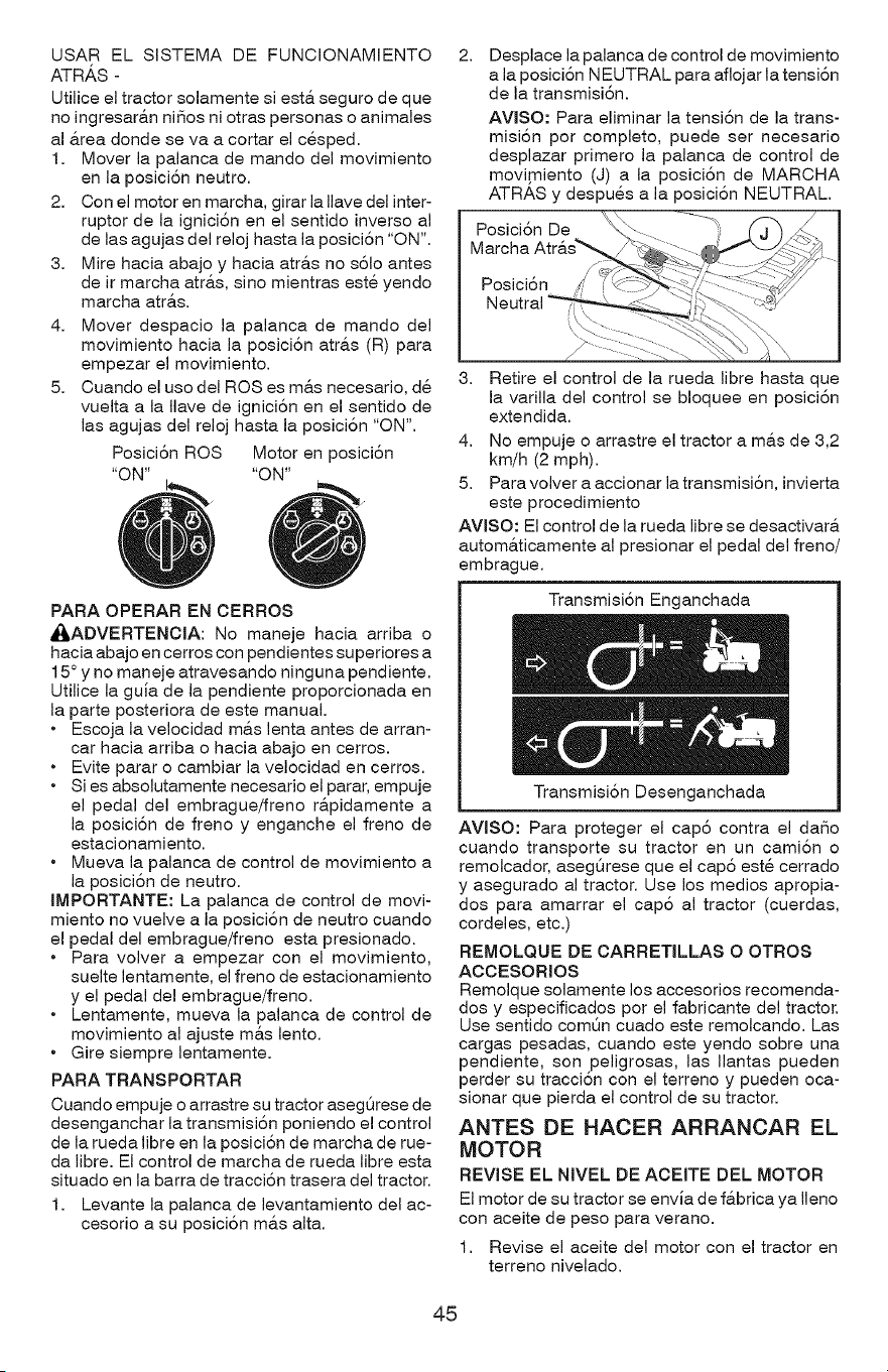
USAR EL SISTEMA DE FUNCIONAMIENTO
ATRA,S -
Utilice el tractor solamente siesta seguro de que
no ingresara.n niSos ni otras personas o animales
al &tea donde se va a cortar el cesped.
1. Mover la palanca de mando del movimiento
en la posici6n neutro.
2. Con el motor en marcha, girar la Ilave del inter-
ruptor de la ignici6n en el sentido inverso al
de las agujas del reloj hasta la posici6n "ON".
3. Mire hacia abajo y hacia atra.s no s61o antes
de ir marcha atr&s, sino mientras este yendo
marcha atr&s.
4. Mover despacio la palanca de mando del
movimiento hacia la posici6n atr&s (R) para
empezar el movimiento.
5. Cuando el uso del ROSes m&s necesario, de
vuelta a la Ilave de ignici6n en el sentido de
las agujas del reloj hasta la posici6n "ON".
Posici6n ROS Motor en posici6n
"ON .... ON"
PARA OPERAR EN CERROS
_ADVERTENOIA: No maneje hacia arriba o
hacia abajo en cerros con pendientes superiores a
15° y no maneje atravesando ninguna pendiente.
Utilice la guia de la pendiente proporcionada en
la parte posteriora de este manual.
• Escoja la velocidad m&s lenta antes de arran-
car hacia arriba o hacia abajo en cerros.
• Evite parar o cambiar la velocidad en cerros.
• Si es absolutamente necesario el parar, empuje
el pedal del embrague/freno r&pidamente a
la posici6n de freno y enganche el freno de
estacionamiento.
• Mueva la palanca de control de movimiento a
la posici6n de neutro.
IMPORTANTE: La palanca de control de movi-
miento no vuelve a la posici6n de neutro cuando
el pedal del embrague/freno esta presionado.
• Para volver a empezar con el movimiento,
suelte lentamente, el freno de estacionamiento
y el pedal del embrague/freno.
• Lentamente, mueva la palanca de control de
movimiento al ajuste m&s lento.
• Gire siempre lentamente.
PARA TRANSPORTAR
Cuando empuje o arrastre su tractor asegQrese de
desenganchar la transmisi6n poniendo el control
de la rueda libre en la posici6n de marcha de rue-
da libre. El control de marcha de rueda libre esta
situado en la barra de tracci6n trasera del tractor.
1. Levante la palanca de levantamiento del ac-
cesorio a su posici6n m&s alta.
2.
Desplace la palanca de control de movimiento
a la posici6n NEUTRAL para aflojar la tensi6n
de la transmisi6n.
AVlSO: Para eliminar la tensi6n de la trans-
misi6n por completo, puede set necesario
desplazar primero la palanca de control de
movimiento (J) a la posici6n de MARCHA
ATRAS y despues a la posici6n NEUTRAL.
Posici6n De
Marcha
3. Retire el control de la rueda libre hasta que
la varilla del control se bloquee en posici6n
extendida.
4. No empuje o arrastre el tractor a m&s de 3,2
km/h (2 mph).
5. Para volver a accionar la transmisi6n, invierta
este procedimiento
AVlSO: El control de la rueda libre se desactivara.
autom&ticamente al presionar el pedal del freno/
embrague.
Transmisi6n Enganchada
Transmisi6n Desenganchada
AVISO: Para proteger el cap6 contra el daSo
cuando transporte su tractor en un cami6n o
remolcador, asegt_rese que el cap6 este cerrado
y asegurado al tractor. Use los medios apropia-
dos para amarrar el cap6 al tractor (cuerdas,
cordeles, etc.)
REMOLQUE DE OARRETILLAS O OTROS
AOOESORIOS
Remolque solamente los accesorios recomenda-
dos y especificados por el fabricante del tractor.
Use sentido comQn cuado este remolcando. Las
cargas pesadas, cuando este yendo sobre una
pendiente, son peligrosas, las Ilantas pueden
perder su tracci6n con el terreno y pueden oca-
sionar que pierda el control de su tractor.
ANTES DE HACER ARRANCAR EL
MOTOR
REVISE EL NIVEL DE AOEITE DEL MOTOR
El motor de su tractor se envia de f&brica ya Ileno
con aceite de peso para verano.
1. Revise el aceite del motor con el tractor en
terreno nivelado.
45
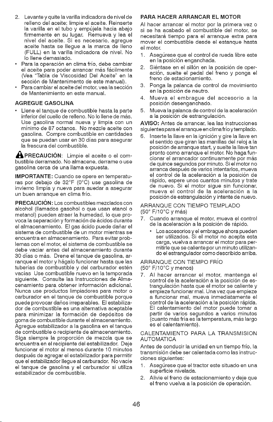
2. Levante y quite la varilla indicadora de nivel de
relleno del aceite; limpie el aceite. Reinserte
la varilla en el tubo y empQjela hacia abajo
firmemente en su lugar. Remueva y lea el
nivel del aceite. Si es necesario, agregue
aceite hasta se Ilegue a la marca de Ileno
(FULL) en la varilla indicadora de nivel. No
Io Ilene demasiado.
• Para la operaci6n en clima frio, debe cambiar
el aceite para poder arrancar m&s f&cilmente
(Vea "Tabla de Viscosidad Del Aceite" en la
secci6n de Mantenimento de este manual).
• Para cambiar el aceite del motor, vea la secci6n
de Mantenimiento en este manual.
AGREGUE GASOUNA
• Llene el tanque de combustible hasta la parte
inferior del cuello de relleno. No Io Ilene de m&s.
Use gasolina normal nueva y limpia con un
mJnimo de 87 octanos. No mezcle aceite con
gasolina. Compre combustible en cantidades
que se puedan usar en 30 dJas para asegurar
la frescura del combustible.
_PREOAUCi6N: Limpie el aceite o el com-
bustible derramado. No almacene, derrame o use
gasolina cerca de una llama expuesta.
IMPORTANTE: Cuando se opere en temperatu-
ras por debajo de 32°F (0°C) use gasolina de
inviemo limpia y nueva para auedar a asegurar
un buen arranque en clima frJo.
PRECAUCI6N: Los combustibles mezclados con
alcohol (llamados gasohol o que usan etanol o
metanol) pueden atraer la humedad, Io que pro-
voca la separaci6n y formaci6n de &cidos durante
el almacenamiento. El gas &cido puede daSar el
sistema de combustible de un motor mientras se
encuentra en almacenamiento. Para evitar prob-
lemas con el motor, el sistema de combustible se
debe vaciar antes del almacenamiento durante
30 dJas o ma.s. Drene el tanque de gasolina, ar-
ranque el motor y h&galo funcionar hasta que las
tuberJas de combustible y del carburador esten
vacJas Use combustible nuevo en la temporada
siguiente. Consulte las Instrucciones de Aima-
cenamiento para obtener informaci6n adicional.
Nunca use productos limpiadores para motor o
carburador en el tanque de combustible porque
puede provocar daSos irreparables. El estabiliza-
dor de combustible es una altemativa aceptable
para minimizar la formaci6n de dep6sitos de
goma de combustible durante el almacenamiento.
Agregue estabilizador a la gasolina en el tanque
de combustible o recipiente de almacenamiento.
Siga siempre la proporci6n de mezcla que se
encuentra en el recipiente del estabilizador. Deje
funcionar el motor al menos durante 10 minutos
despues de agregar el estabilizador para permitir
que el estabilizadorllegueal carburador. NovacJe
el tanque de gasolina y el carburador si utiliza
estabilizador de combustible.
PARA HACER ARRANCAR EL MOTOR
AI hacer arrancar el motor por la primera vez o
si se ha acabado el combustible del motor, se
necesitar& tiempo para el arranque extra para
mover el combustible desde el estanque hasta
el motor.
1. AsegQrese.,que el control de rueda libre este
en la posiclon enganchada.
2. Sientase en el sill6n en la posici6n de oper-
aci6n, suelte el pedal del freno y ponga el
freno de estacionamiento.
3. Ponga la palanca de control de movimiento
en la posici6n de neutro.
4. Mueva el embrague del accesorio a la
posici6n desenganchado.
5. Mueva la palanca de control de la aceleraci6n
a la posici6n de estrangulaci6n.
AVlSO: Antes de arrancar, lea las instrucciones
siguientes para el arranque en climafrio ytemplado.
6. Inserte la Ilave en la ignici6n y gire la Ilave en
el sentido que giran las manillas del reloj a la
posici6n de arranque start, y suelte la Ilave tan
pronto como arranque el motor. No haga fun-
cionar el arrancador continuamente por m&s
de quince segundos por minuto. Si el motor no
arranca despues de varios intentarlos, mueva
el control de la aceleraci6n a la posici6n de
r&pido, espere unos cuantos minutos y trate
de nuevo. Si el motor sigue sin funcionar,
mueva el control de la aceleraci6n a la
posici6n de estrangulaci6n y intente de nuevo.
ARRANQUE CON TIEMPO TEMPLADO
(50 ° F/10°C y m&s)
7. Cuando arranque el motor, mueva el control
de la aceleraci6n a la posici6n de r&pido.
• Los accesorios y el embrague ahora pueden
ser utilizados. Si el motor no acepta esta
carga, vuelva a arrancar el motor para per-
mitirle que se caliente por un minuto utilizan-
do el estrangulador como describido arriba.
ARRANQUE CON TIEMPO FRiO
(50 ° F/10°C y menos)
7. AI hacer arrancar el motor, mantenga el
control de la aceleraci6n a la posici6n de es-
trangulaci6n hasta que el motor se caliente y
empieze funcionar mal. Unavez que empieze
a funcionar mal, mueva inmediatamente el
control de la aceleraci6n a la posici6n r&pida.
El calentamiento del motor puede tomar a
partir de varios segundos a varios minutos
(cuanto m_.s fria es la temperatura, m&s largo
es el calentamiento).
CALENTAMIENTO PARA LA TRANSMISION
AUTOMATICA
Antes de conducir la unidad en un tiempo frJo, la
transmisi6n debe ser calentada como las instruc-
clones siguientes:
1. AsegOrese que el tractor este situado en una
superficie nivelada.
2. Alivie el freno de estacionamiento y deje que
el freno vuelva a la posici6n de operaci6n.
46
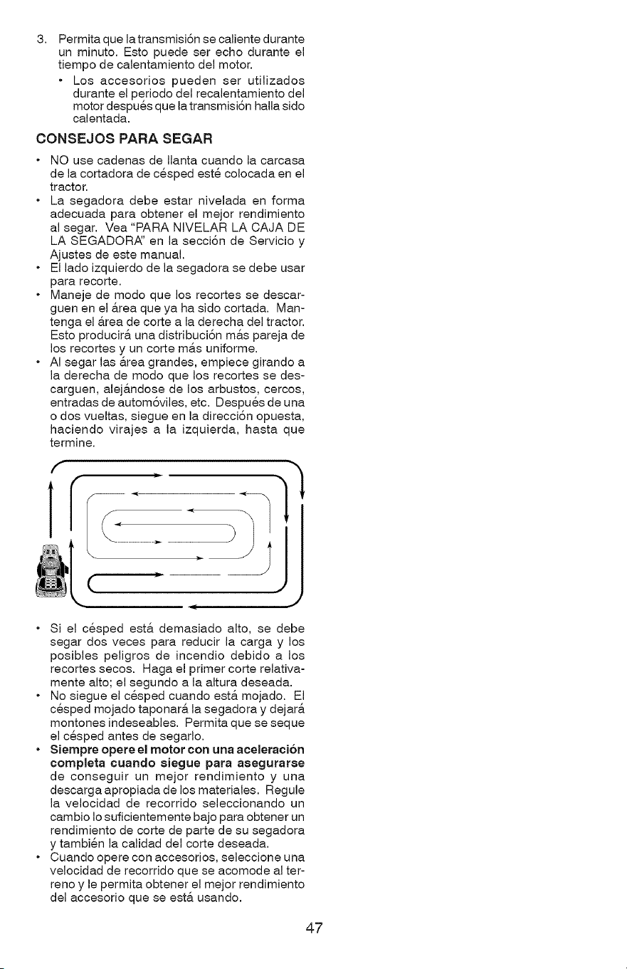
3,
Permita que la transmisi6n se caliente durante
un minuto. Esto puede ser echo durante el
tiempo de calentamiento del motor.
• Los accesorios pueden ser utilizados
durante el periodo del recalentamiento del
motor despues que la transmisi6n halla sido
calentada.
CONSEJOS PARA SEGAR
o
o
NO use cadenas de Ilanta cuando la carcasa
de la cortadora de cesped este colocada en el
tractor.
La segadora debe estar nivelada en forma
adecuada para obtener el mejor rendimiento
al segar. Vea "PARA NIVELAR LA CAJA DE
LA SEGADORA:' en la secci6n de Servicio y
Ajustes de este manual.
El lado izquierdo de la segadora se debe usar
para recorte.
Maneje de modo que los recortes se descar-
guen en el a.rea que ya ha sido cortada. Man-
tenga el _.rea de corte a la derecha del tractor.
Esto producir& una distribuci6n m&s pareja de
los recortes y un corte m&s uniforme.
AI segar las &rea grandes, empiece girando a
la derecha de modo que los recortes se des-
carguen, alej&ndose de los arbustos, cercos,
entradas de autom6viles, etc. Despues de una
o dos vueltas, siegue en la direcci6n opuesta,
haciendo virajes a la izquierda, hasta que
termine.
(
, J
Si el cesped esta demasiado alto, se debe
segar dos veces para reducir la carga y los
posibles peligros de incendio debido a los
recortes secos. Haga el primer corte relativa-
mente alto; el segundo a la altura deseada.
No siegue el cesped cuando est& mojado. El
cesped mojado taponar& la segadora y dejar&
montones indeseables. Permita que se seque
el cesped antes de segarlo.
Siempre opere el motor con una aceleraci6n
completa cuando siegue para asegurarse
de conseguir un mejor rendimiento y una
descarga apropiada de los materiales. Regule
la velocidad de recorrido seleccionando un
cambio Io suficientemente bajo para obtener un
rendimiento de corte de parte de su segadora
y tambien la calidad del corte deseada.
Cuando opere con accesorios, seleccione una
velocidad de recorrido que se acomode al ter-
reno y le permita obtener el mejor rendimiento
del accesorio que se esta usando.
47
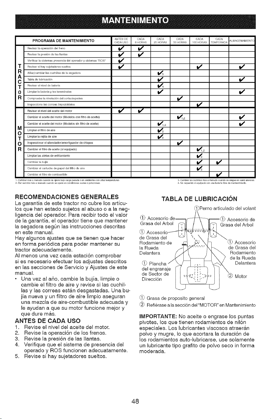
PROGRAMA DE MANTENIMtENTO ANTES DE CADA CADA CADA CADA CADA &LMACENAMIENTC
CADA USO 8 HORAS 25 HORAS 50 HORAS 100 HORAS TEMPORADA
Revisar la opelaci6n del freno _
Revisar la presi6n de las Ilal_tas _
Verificar _a sistemas presencia del operador y sbtemas "ROS'
T ............... j............... _ If
a Afilar,cambiar las cuchillas de la segadora _3
T_bla de lubricacian if
T Revisar el lsivel de bateria _4
0 Limpiar la bateria y ios tereminales V _ V _
R Compruebe la nivelaci6n del cortac6spedes
I_speccione _as correas trapezoidales
Revisar el nivel del aoeite del motor _
Cambiar el aceite del motor (Modelos con filtro de aceit e) _1,2
Cambiar el aceite del motor (Modelos sin fillro de aceite) _1,2
Umpiar el filtro de aire _2
T Limpiar la re}ilia de aire _2
O Inspeccionar el silenciador/amor tiguador de chispas
R Cambiar el filtro de aceite (si equipado) _1,2
Umpiar las alelas de enfdamienlo _2
Cambiar el caducho de pape_ de_ filtro de aire _2
Cambiar el fi_bo de combustible
3- CambJaf las cuchfllas m_s a menudo cuando se slegue en _uelo areaoso
4- No reque 1dosl equipado con usa bate fa Ilbfe de mantealmlento
1. CambJar mas a meaudo ouaado se opere baJo oarga pesada o en ambJeates con altas temperaturas
2- Dar sefv4clo m,_s a menudo ouaado se opere en condlclones suclas o pol_ro_s
RECOMENDACIONES GENERALES
La garantia de este tractor no cubre los articu-
los que han estado sujetos al abuso o a la neg-
ligencia del operador. Para recibir todo el valor
de la garantia, el operador tiene que mantener
la segadora seg6n las instrucciones descritas
en este manual.
Hay algunos ajustes que se tienen que hacer
en forma peri6dica para poder mantener su
tractor adecuadamente.
AI menos una vez cada estaci6n comprobar
si es necesario efectuar los adjustes descritos
en las secciones de Servicio y Ajustes de este
manual.
• Una vez al a_o, cambie la bujia, limpie o
cambie el filtro de aire y revise si las cuchil-
las y las correas esta.n desgastadas. Una bu-
jia nueva y un filtro de aire limpio aseguran
una mezcla de aire-combustible adecuada y
le ayudan a que su motor funcione mejor y
que dure m&s.
ANTES DE CADA USO
1. Revise el nivel del aceite del motor.
2. Revise la operaci6n de los frenos.
3. Revise la presi6n de las Ilantas.
4. Verifique que el sistema de presencia del
operado y ROS funcionen adecuatamente.
5. Revise si hay sujetadores sueltos.
TABLA DE LUBRICACI6N
(_ Accesorio
Grasa del Arbol
@
de Grasa del
Rodamiento de
la Rueda
Delantera
_Perno articulado del volant
@
del engranaje
de Sector de
Direcci6n
Accesorio de
Grasa del Arbol
Accesorio
de Grasa del
Rodamiento
de la Rueda
Delantera
Motor
(_) Grasa de proposito general
Refi@ase a la secci6n del "MOTOR" en Mantenimiento
IMPORTANTE: No aceite o engrase los puntas
pivotes, los que tienen rodamientos de nil6n
especiales. Los lubricantes viscosos atraera.n
polvo y mugre, Io que acortara la duraci6n de
los rodamientos auto-lubricarse, use solamente
un lubricante tipo grafito de polvo seco in forma
moderada.
48
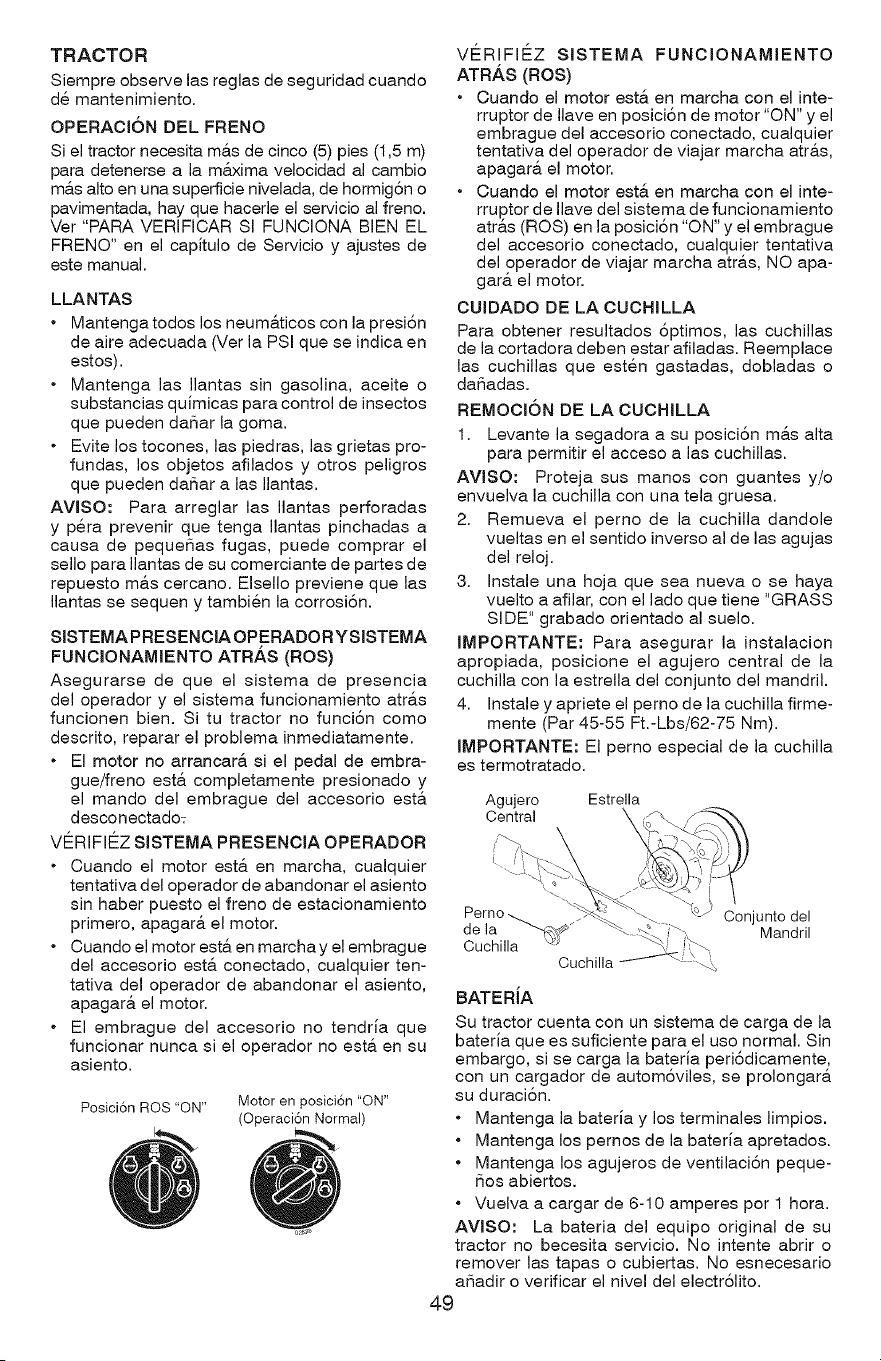
TRACTOR
Siempre observe las reglas de seguridad cuando
de mantenimiento.
OPERACI6N DEL FRENO
Si el tractor necesita m&s de cinco (5) pies (1,5 m)
para detenerse a la m&xima velocidad al cambio
m&s alto en una superficie nivelada, de hormig6n o
pavimentada, hay que hacerle el servicio al freno.
Ver "PARA VERIFICAR SI FUNCIONA BIEN EL
FRENO" en el capitulo de Servicio y ajustes de
este manual.
LLANTAS
• Mantengatodos los neum&ticos con la presi6n
de aire adecuada (Ver la PSi que se indica en
estos).
• Mantenga las Ilantas sin gasolina, aceite o
substancias quimicas para control de insectos
que pueden daSar la goma.
• Evite los tocones, las piedras, las grietas pro-
fundas, los objetos afilados y otros peligros
que pueden daSar alas Ilantas.
AVlSO: Para arreglar las Ilantas perforadas
y pera prevenir que tenga Ilantas pinchadas a
causa de pequeSas fugas, puede comprar el
sello para Ilantas de su comerciante de partes de
repuesto m&s cercano. Elsello previene que las
Ilantas se sequen y tambien la corrosi6n.
SlSTEMA PRESENCIA OPERADOR Y SISTEMA
FUNCIONAMIENTO ATR/_S (ROS)
Asegurarse de que el sistema de presencia
del operador y el sistema funcionamiento atr&s
funcionen bien. Si tu tractor no funci6n como
descrito, reparar el problema inmediatamente.
• El motor no arrancarA si el pedal de embra-
gue/freno est& completamente presionado y
el mando del embrague del accesorio est&
desconectado:
VE_RIFIE_Z SISTEMA PRESENCIA OPERADOR
• Cuando el motor est& en marcha, cualquier
tentativa del operador de abandonar el asiento
sin haber puesto el freno de estacionamiento
primero, apagar& el motor.
• Cuando el motor est& en marcha y el embrague
del accesorio est& conectado, cualquier ten-
tativa del operador de abandonar el asiento,
apagar& el motor.
• El embrague del accesorio no tendria que
funcionar nunca si el operador no est& en su
asiento.
Posici6n ROS "ON" Motor en posici6n "ON"
(Operaci6n Normal)
VE_RIFIE_Z SISTEMA FUNCIONAMIENTO
ATR.&S (ROS)
• Cuando el motor estA en marcha con el inte-
rruptor de Ilave en posici6n de motor "ON" y el
embrague del accesorio conectado, cualquier
tentativa del operador de viajar marcha atr&s,
apagar& el motor.
• Cuando el motor estA en marcha con el inte-
rruptor de Ilave del sistema de funcionamiento
atr&s (ROS) en la posici6n "ON" y el embrague
del accesorio conectado, cualquier tentativa
del operador de viajar marcha atr&s, NO apa-
gar& el motor.
CUIDADO DE LA CUCHILLA
Para obtener resultados 8ptimos, las cuchillas
de la cortadora deben estar afiladas. Reemplace
las cuchillas que esten gastadas, dobladas o
daSadas.
REMOCION DE LA CUCHILLA
1. Levante la segadora a su posici6n m&s alta
para permitir el acceso alas cuchillas.
AVlSO: Proteja sus manos con guantes y/o
envuelva la cuchilla con una tela gruesa.
2. Remueva el perno de la cuchilla dandole
vueltas en el sentido inverso al de las agujas
del reloj.
3. Instale una hoja que sea nueva o se haya
vuelto a afilar, con el lado que tiene "GRASS
SIDE" grabado orientado al suelo.
IMPORTANTE: Para asegurar la instalacion
apropiada, posicione el agujero central de la
cuchilla con la estrella del conjunto del mandril.
4. Instale y apriete el perno de la cuchilla firme-
mente (Par 45-55 Ft.-Lbs/62-75 Nm).
IMPORTANTE: El perno especial de la cuchilla
es termotratado.
Agujero Estrella
Central
de la
Cuchilla
Conjunto del
Mandril
Cuchilla
BATERIA
Su tractor cuenta con un sistema de carga de la
bateria que es suficiente para el uso normal. Sin
embargo, si se carga la bateria periSdicamente,
con un cargador de autom6viles, se prolongar&
su duraciSn.
• Mantenga la bateria y los terminales limpios.
• Mantenga los pernos de la bateria apretados.
• Mantenga los agujeros de ventilaciSn peque-
5os abiertos.
• Vuelva a cargar de 6-10 amperes por 1 hora.
AVISO: La bateria del equipo original de su
tractor no becesita servicio. No intente abrir o
remover las tapas o cubiertas. No esnecesario
aSadir o verificar el nivel del electrSlito.
49
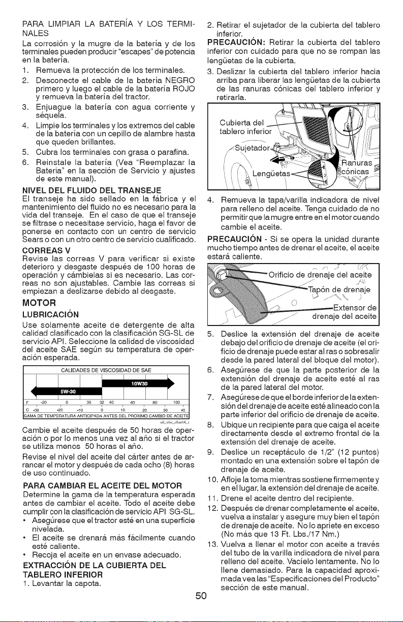
PARA LIMPIAR LA BATERiA Y LOS TERMI-
NALES
La corrosi6n y la mugre de la bateria y de los
terminales pueden producir "escapes" de potencia
en la bateria.
1. Remueva la protecci6n de los terminales.
2. Desconecte el cable de la bateria NEGRO
primero y luego el cable de la bateria ROJO
y remueva la bateria del tractor.
3. Enjuague la bateria con agua corriente y
sequela.
4. Limpie los terminales y los extremos del cable
de la bateria con un cepillo de alambre hasta
que queden brillantes.
5. Cubra los terminales con grasa o parafina.
6. Reinstale la bateria (Vea "Reemplazar la
Bateria" en la secci6n de Servicio y ajustes
de este manual).
NJVEL DEL FLUIDO DEL TRANSEJE
El transeje ha sido sellado en la f&brica y el
mantenimiento del fluido no es necesario para la
vida del transeje. En el caso de que el transeje
se filtrase o necesitase servicio, haga el favor de
ponerse en contacto con un centro de servicio
Sears o con un otro centro de servicio cualificado.
CORREAS V
Revise las correas V para verificar si existe
deterioro y desgaste despues de 100 horas de
operaci6n y c&mbielas si es necesario. Las cor-
teas no son ajustables. Cambie las correas si
empiezan a deslizarse debido al desgaste.
MOTOR
LUBRIOAOI6N
Use solamente aceite de detergente de alta
calidad clasificado con la clasificaci6n SG-SL de
servicio API. Seleccione la calidad de viscosidad
del aceite SAE segQn su temperatura de oper-
aci6n esperada.
o11vlscch_rt4 s
Cambie el aceite despues de 50 horas de oper-
aci6n o por Io menos una vez al aSo si el tractor
se utiliza menos 50 horas el aSo.
Revise el nivel del aceite del c&rter antes de ar-
rancar el motor y despues de cada ocho (8) horas
de uso continuado.
PARA CAMBIAR EL ACEITE DEL MOTOR
Determine la gama de la temperatura esperada
antes de cambiar el aceite. Todo el aceite debe
cumplir con la clasificaci6n de servicio API SG-SL.
• Asegt_rese que el tractor este en una superficie
nivelada.
• El aceite se drenar& m&s f&cilmente cuando
este caliente.
• Recoja el aceite en un envase adecuado.
EXTRAOOI6N DE LA CUBIERTA DEL
TABLERO INFERIOR
1. Levantar la capota.
2. Retirar el sujetador de la cubierta del tablero
inferior.
PREOAUOJON: Retirar la cubierta del tablero
inferior con cuidado para que no se rompan las
lengQetas de la cubierta.
3. Deslizar la cubierta del tablero inferior hacia
arriba para liberar las lengL_etas de la cubierta
de las ranuras c6nicas del tablero inferior y
retirarla.
50
Cubierta del
4. Remueva la tapa/varilla indicadora de nivel
para relleno del aceite. Tenga cuidado de no
permitir que la mugre entre en el motor cuando
cambie el aceite.
PREOAUOION - Si se opera la unidad durante
mucho tiempo antes de drenar el aceite, el aceite
estar& caliente.
drenaje del aceite I
Jap6n de drenZ'ae
._,.--_ E,':tensor de
......... drenaje del aceite
5. Deslice la extensi6n del drenaje de aceite
debajo del orificio de drenaje de aceite (el ori-
ficio de drenaje puede estar al ras o sobresalir
desde la pared lateral del bloque del motor).
6. Aseg@ese de que la parte posterior de la
extensi6n del drenaje de aceite este al ras
de la pared lateral del motor.
7. AsegQrese de que el borde inferior de la exten-
si6n del drenaje de aceite este alineado con la
parte inferior del orificio de drenaje de aceite.
8. Ubique un recipiente para que caiga el aceite
directamente desde el extremo frontal de la
extensi6n del drenaje de aceite.
9. Deslice un recept&culo de 1/2" (12 puntos)
montado en una extensi6n sobre el tap6n de
drenaje de aceite.
10. Afloje la toma mientras sostiene firmemente y
en el lugar, la extensi6n del drenaje de aceite.
11. Drene el aceite dentro del recipiente.
12. Despues de drenar completamente el aceite,
vuelva a instalar y asegure muy bien el tap6n
de drenaje de aceite. No Io apriete en exceso
(No m&s que 13 Ft. Lbs./17 Nm.)
13. Vuelva a Ilenar el motor con aceite a traves
del tubo de la varilla indicadora de nivel para
relleno del aceite. Vacielo lentamente. No Io
Ilene demasiado. Para la capacidad aproxi-
madavea las"Especificaciones del Producto"
secci6n de este manual.
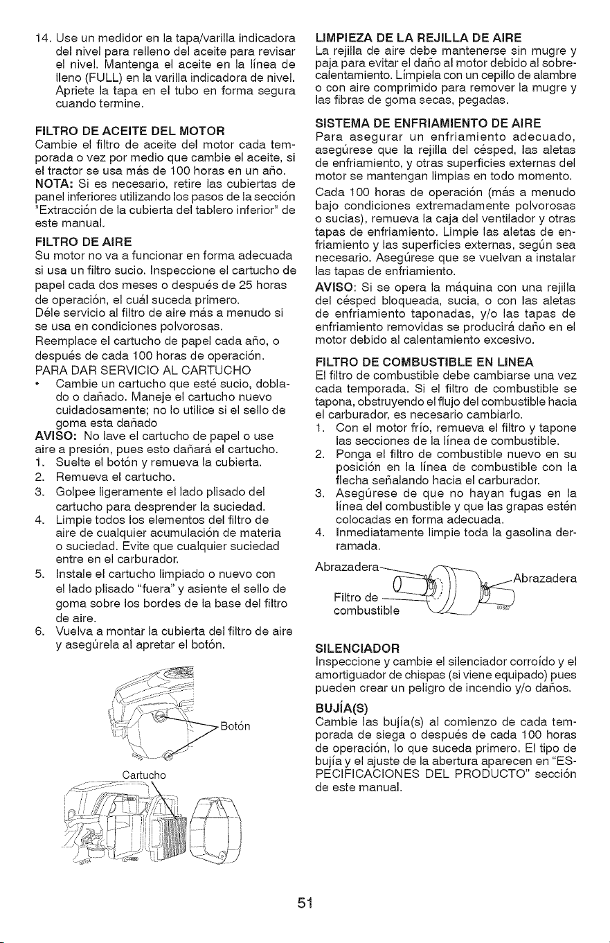
14.Useunmedidorenlatapa/varillaindicadora
delnivelpararellenodelaceitepararevisar
elnivel.Mantengaelaceiteenlalineade
Ileno(FULL)enlavarillaindicadoradenivel.
Aprietelatapaeneltuboenformasegura
cuandotermine.
FILTRODEACEITEDELMOTOR
Cambieelfiltrodeaceitedelmotorcadatem-
poradaovezpormedicquecambieelaceite,si
eltractorseusam&sde100horasenunaSo.
NOTA:Siesnecesario,retirelascubiertasde
panelinferioresutilizandolospasosdelasecci6n
"Extracci6n de la cubierta del tablero inferior" de
este manual.
FILTRO DE AIRE
Su motor no va a funcionar en forma adecuada
si usa un filtro sucio. Inspeccione el cartucho de
papel cada dos meses o despues de 25 horas
de operaci6n, el cu&l suceda primero.
Dele servicio al filtro de aire m&s a menudo si
se usa en condiciones polvorosas.
Reemplace el cartucho de papel cada aSo, o
despues de cada I00 horas de operaci6n.
PARA DAR SERVICIO AL CARTUCHO
Cambie un cartucho que este sucio, dobla-
do o daSado. Maneje el cartucho nuevo
cuidadosamente; no Io utilice si el sello de
goma esta daSado
AVlSO: No lave el cartucho de papel o use
aire a presi6n, pues esto daSar& el cartucho.
1. Suelte el bot6n y remueva la cubierta.
2. Remueva el cartucho.
3. Golpee ligeramente el lado plisado del
cartucho para desprender la suciedad.
4. Limpie todos los elementos del filtro de
aire de cualquier acumulaci6n de materia
o suciedad. Evite que cualquier suciedad
entre en el carburador.
5. Instale el cartucho limpiado o nuevo con
el lado plisado "fuera" y asiente el sello de
goma sobre los bordes de la base del filtro
de aire.
6. Vuelva a montar la cubierta del filtro de aire
y asegQrela al apretar el bot6n.
Bot6n
. J
Cartucho
LIMPIEZA DE LA REJILLA DE AIRE
La rejilla de aire debe mantenerse sin mugre y
paja para evitar el daSo al motor debido al sobre-
calentamiento. Limpiela con un cepillo de alambre
o con aire comprimido para remover la mugre y
las fibras de goma secas, pegadas.
SISTEMA DE ENFRIAMIENTO DE AIRE
Para asegurar un enfriamiento adecuado,
aseg_rese que la rejilla del cesped, las aletas
de enfriamiento, y otras superficies externas del
motor se mantengan limpias en todo momento.
Cada 100 horas de operaci6n (m&s a menudo
bajo condiciones extremadamente polvorosas
o sucias), remueva la caja del ventilador y otras
tapas de enfriamiento. Limpie las aletas de en-
friamiento y las superficies externas, segOn sea
necesario. AsegOrese que se vuelvan a instalar
las tapas de enfriamiento.
AVlSO: Si se opera la m&quina con una rejilla
del cesped bloqueada, sucia, o con las aletas
de enfriamiento taponadas, y/o las tapas de
enfriamiento removidas se producir& daSo en el
motor debido al calentamiento excesivo.
FILTRO DE COMBUSTIBLE EN LINEA
El filtro de combustible debe cambiarse una vez
cada temporada. Si el filtro de combustible se
tapona, obstruyendo el flujo del combustible hacia
el carburador, es necesario cambiarlo.
1. Con el motor frio, remueva el filtro y tapone
las secciones de la linea de combustible.
2. Ponga el filtro de combustible nuevo en su
posiciSn en la linea de combustible con la
flecha seSalando hacia el carburador.
3. AsegQrese de que no hayan fugas en la
linea del combustible y que las grapas esten
colocadas en forma adecuada.
4. Inmediatamente limpie toda la gasolina der-
ramada.
Filtro de
combustible
SlLENCIADOR
Inspeccione y cambie el silenciador corroido y el
amortiguador de chispas (si viene equipado) pues
pueden crear un peligro de incendio y/o da_os.
BUJiA(S)
Cambie las bujia(s) al comienzo de cada tem-
porada de siega o despues de cada 100 horas
de operaci6n, Io que suceda primero. El tipo de
bujia y el ajuste de la abertura aparecen en "ES-
PECIFICACIONES DEL PRODUCTO" secci6n
de este manual.
51
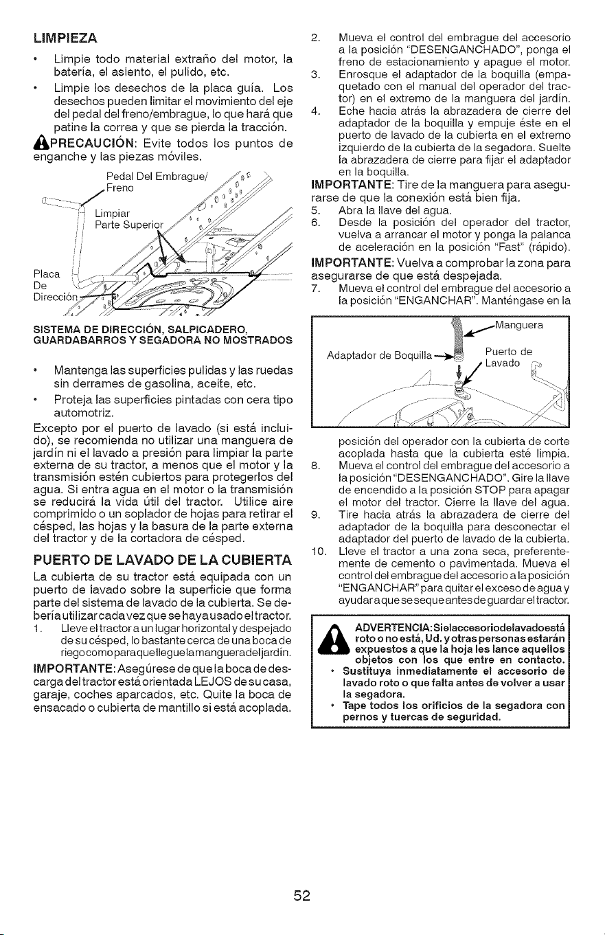
LIMPIEZA
Limpie todo material extraSo del motor, la
bateria, el asiento, el pulido, etc.
Limpie los desechos de la placa guia. Los
desechos pueden limitar el movimiento del eje
del pedal del freno/embrague, Io que hara. que
patine la correa y que se pierda la tracci6n.
_,PRECAUCI6N: Evite todos los puntos de
enganche y las piezas m6viles.
SISTEMA DE DIRECCION, SALPmCADERO,
GUARDABARROS Y SEGADORA NO MOSTRADOS
Mantenga las superficies pulidas y las ruedas
sin derrames de gasolina, aceite, etc.
Proteja las superficies pintadas con cera tipo
automotriz.
Excepto por el puerto de lavado (siest& inclui-
do), se recomienda no utilizar una manguera de
jardin ni el lavado a presi6n para limpiar la parte
externa de su tractor, a menos que el motor y la
transmisi6n esten cubiertos para protegerlos del
agua. Si entra agua en el motor o la transmisi6n
se reducir& la vida Otil del tractor. Utilice aire
comprimido o un soplador de hojas para retirar el
cesped, las hojas y la basura de la parte extema
del tractor y de la cortadora de cesped.
PUERTO DE LAVADO DE LA CUBIERTA
La cubierta de su tractor est& equipada con un
puerto de lavado sobre la superficie que forma
parte del sistema de lavado de la cubierta. Se de-
beria util izar cada v ez que se ha ya usado el tractor.
1. Lleve el tractor a un lugar horizontal y despejado
de su c6sped, Io bastante cerca de una boca de
dego como paraquelleguelamangueradeljardin.
IMPORTANTE: AsegQrese de que la boca de des-
cargadeltractor est&orientada LEJOS de su casa,
garaje, coches aparcados, etc. Quite la boca de
ensacado o cubierta de mantillo siest& acoplada.
2. Mueva el control del embrague del accesorio
a la posici6n "DESENGANCHADO", ponga el
freno de estacionamiento y apague el motor.
3. Enrosque el adaptador de la boquilla (empa-
quetado con el manual del operador del trac-
tor) en el extremo de la manguera del jardin.
4. Eche hacia atras la abrazadera de cierre del
adaptador de la boquilla y empuje este en el
puerto de lavado de la cubierta en el extremo
izquierdo de la cubierta de la segadora. Suelte
la abrazadera de cierre para fijar el adaptador
en la boquilla.
IMPORTANTE: Tire de la manguera para asegu-
rarse de que la conexi6n est& bien fija.
5. Abra la Ilave del agua.
6. Desde la posici6n del operador del tractor,
vuelva a arrancar el motor y ponga la palanca
de aceleraci6n en la posici6n "Fast" (rapido).
IMPORTANTE: Vuelva a comprobar la zona para
asegurarse de que esta. despejada.
7. Mueva el control del embrague del accesorio a
la posici6n "ENGANCHAR". Mantengase en la
,,,,1-Mang uera
Adaptador de Boquilla---)_._ Puerto de
posici6n del operador con la cubierta de corte
acoplada hasta que la cubierta este limpia.
8. Mueva el control del embrague del accesorio a
la posici6n "DESENGANCHADO". Gire la Ilave
de encendido a la posici6n STOP para apagar
el motor del tractor. Cierre la Ilave del agua.
9. Tire hacia atrb, s la abrazadera de cierre del
adaptador de la boquilla para desconectar el
adaptador del puerto de lavado de la cubierta.
10. Lleve el tractor a una zona seca, preferente-
mente de cemento o pavimentada. Mueva el
control del embrague del accesorio ala posici6n
"ENGANCHAR" para quitar el exceso de agua y
ayudar a q ue se seq ue antes de g uardar el tractor.
& ADVERTENClA:Sielaccesoriodelavadoesta
roto o no est,, Ud. yotras personas estaran
expueetos a que la hoja lee lance aquellos
objetos con mosque entre en eontaeto.
• Sustituya inrnediatamente el aecesorio de
lavado roto o que falta antes de volver a usar
la segadora.
• Tape todos los orificios de la segadora con
pernos y tuercas de seguridad.
52
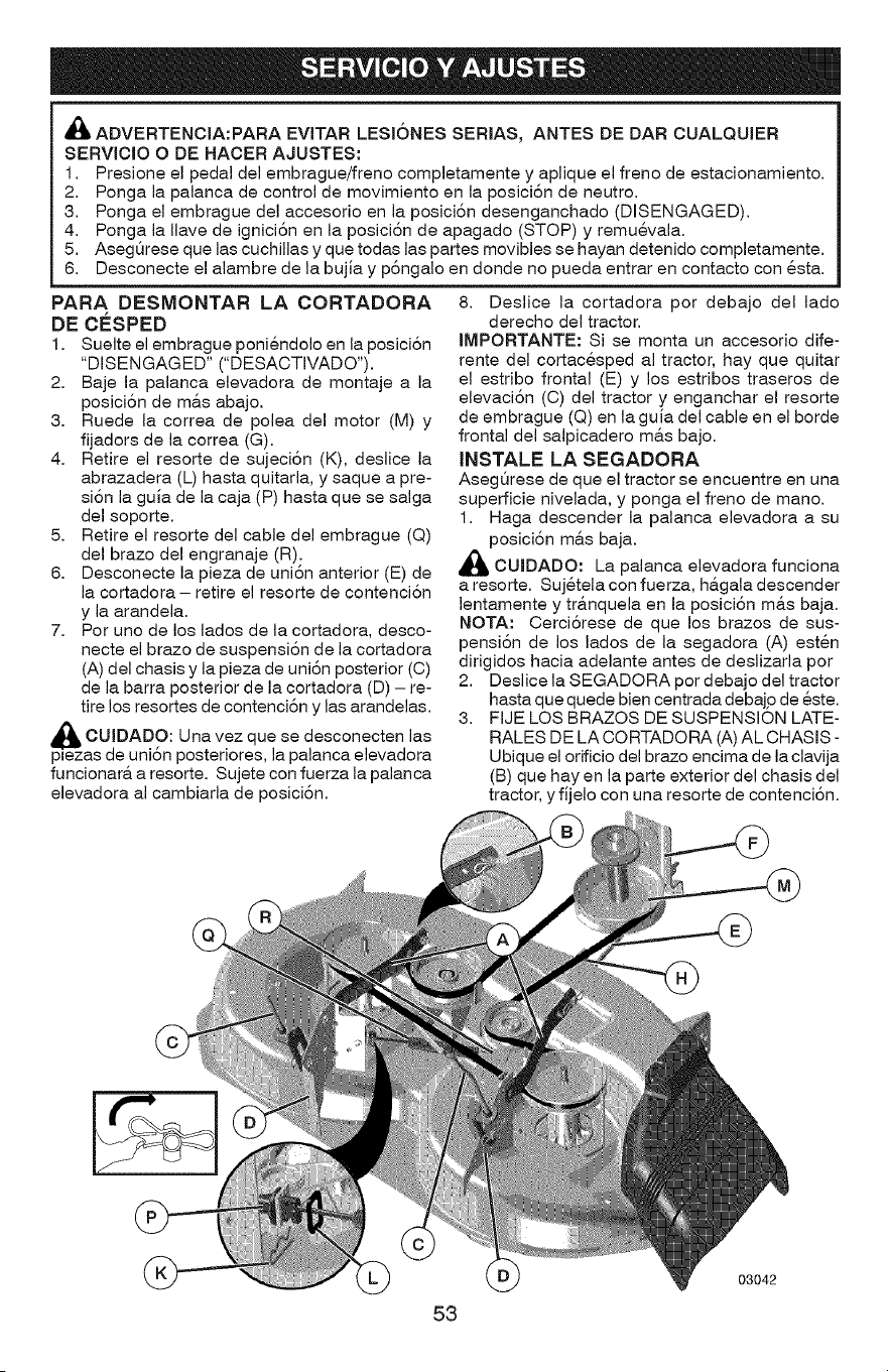
,_i ADVERTENCIA:PARA EVITAR LESI6NES SERIAS, ANTES DE DAR CUALQUIER
SERVICIO O DE HACER AJUSTES:
1. Presione el pedal del embrague/freno completamente y aplique el freno de estacionamiento.
2. Ponga la palanca de control de movimiento en la posici6n de neutro.
3. Ponga el embrague del accesorio en la posici6n desenganchado (DISENGAGED).
4. Ponga la Ilave de ignici6n en la posici6n de apagado (STOP) y remuevala.
5. AsegSrese que las cuchillas y que todas las partes movibles se hayan detenido completamente.
6. Desconecte el alambre de la bujia y p6ngalo en donde no pueda entrar en contacto con esta.
PARA DESMONTAR LA CORTADORA
oE c#sPEo
1. Suelte el embrague poniendolo en la posici6n
"DISENGAGED" ("DESACTWADO").
2. Baje la palanca elevadora de montaje a la
posici6n de m&s abajo.
3. Ruede la correa de polea del motor (M) y
fijadors de la correa (G).
4. Retire el resorte de sujeci6n (K), deslice la
abrazadera (L) hasta quitarla, y saque a pre-
si6n la guia de la caja (P) hasta que se salga
del soporte.
5. Retire el resorte del cable del embrague (Q)
del brazo del engranaje (R).
6. Desconecte la pieza de uni6n anterior (E) de
la cortadora - retire el resorte de contenci6n
y la arandela.
7. Por uno de los lados de la cortadora, desco-
necte el brazo de suspensi6n de la cortadora
(A) del chasis y la pieza de uni6n posterior (C)
de la barra posterior de la cortadora (D) - re-
tire los resortes de contenci6n y las arandelas.
CUIDADO: vez que se
Una desconecten las
plezas de uni6n posteriores, la palanca elevadora
funcionar& a resorte. Sujete con fuerza la palanca
elevadora al cambiarla de posici6n.
8. Deslice la cortadora por debajo del lado
derecho del tractor.
IMPORTANTE: Si se monta un accesorio dife-
rente del cortacesped al tractor, hay que quitar
el estribo frontal (E) y los estribos traseros de
elevaci6n (C) del tractor y enganchar el resorte
de embrague (Q) en la guia del cable en el borde
frontal del salpicadero m&s bajo.
JNSTALE LA SEGADORA
AsegQrese de que el tractor se encuentre en una
superficie nivelada, y ponga el freno de mano.
1. Haga descender la palanca elevadora a su
posici6n m&s baja.
_lk CUIDADO: La palanca elevadora funciona
a resorte. Sujetela con fuerza, h&gala descender
lentamente y tr&nquela en la posici6n m&s baja.
NOTA: Cerci6rese de que los brazos de sus-
pensi6n de los lados de la segadora (A) esten
dirigidos hacia adelante antes de deslizarla por
2. Deslice la SEGADORA pot debajo del tractor
hasta que quede bien centrada debajp de este.
3. FIJE LOS BRAZOS DE SUSPENSION LATE-
RALES DE LA CORTADORA (A) AL CHASIS -
Ubique el orificio del brazo encima de la clavija
(B) que hay en la parte exterior del chasis del
tractor, y fijelo con una resorte de contenci6n.
53
03042
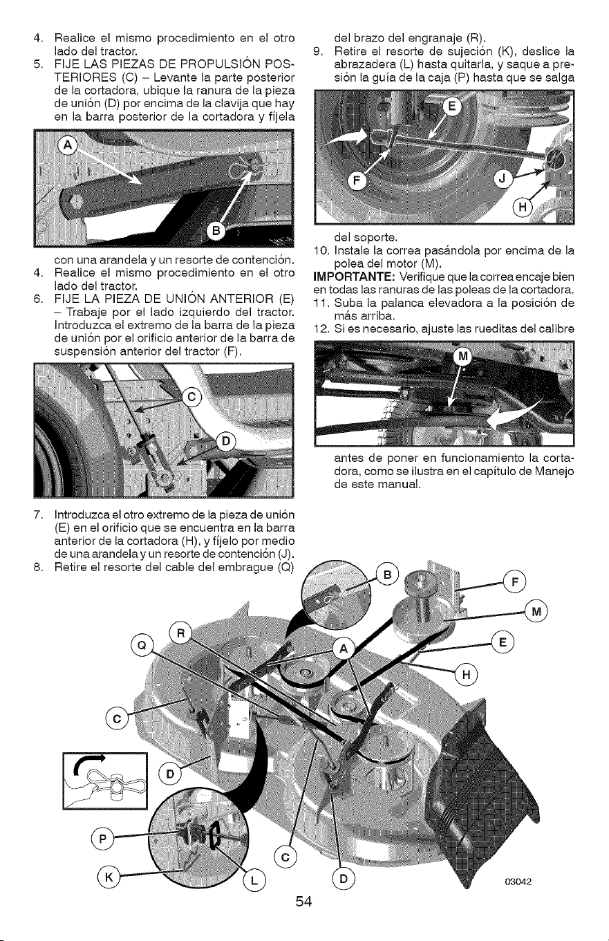
4.
5.
Realice el mismo procedimiento en el otro
lado del tractor.
FIJE LAS PIEZAS DE PROPULSI6N POS-
TERIORES (C) - Levante la parte posterior
de la cortadora, ubique la ranura de la pieza
de uniSn (D) por encima de la clavija que hay
en la barra posterior de la cortadora y fijela
9.
del brazo del engranaje (R).
Retire el resorte de sujeci6n (K), deslice la
abrazadera (L) hasta quitarla, y saque a pre-
si6n la guia de la caja (P) hasta que se salga
4.
6.
con una arandela y un resorte de contenciSn.
Realice el mismo procedimiento en el otro
lado del tractor.
FIJE LA PIEZA DE UNION ANTERIOR (E)
- Trabaje por el lado izquierdo del tractor.
Introduzca el extremo de la barra de la pieza
de uniSn por el orificio anterior de la barra de
suspensiSn anterior del tractor (F).
del soporte.
10. Instale la correa pas&ndola por encima de la
polea del motor (M).
IMPORTANTE: Verifique que la correa encaje bien
en todas las ranuras de las poleas de la cortadora.
11. Suba la palanca elevadora a la posiciSn de
m&s arriba.
12. Si es necesario, ajuste las rueditas del calibre
7. Introduzca el otro extremo de la pieza de uni6n
(E) en el orificio que se encuentra en la barra
anterior de la cortadora (H), y fijelo por medio
de una arandela y un resorte de contenciSn (J).
8. Retire el resorte del cable del (Q)
antes de poner en funcionamiento la corta-
dora, como se ilustra en el capitulo de Manejo
de este manual.
54
03042
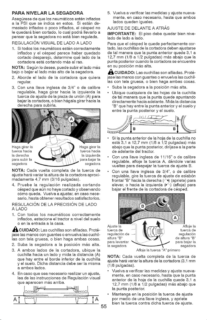
PARA NIVELAR LA SEGADORA
AsegQrese de que los neum&ticos esten inflados
a la PSI que se indica en estos. Si est_,n de-
masiado inflados o poco inflados, el cesped no
le quedar& bien cortado, Io cual podr& Ilevarlo a
pensar que la segadora no est& bien regulada.
REGULACION VISUAL DE LADO A LADO
1. Si todos los neum&ticos est&n correctamente
inflados y el cesped parece haber quedado
cortado desparejo, determine que lado de la
cortadora esta. cortando ma.s al ras.
NOTA: SegQn Io desee, puede subir el lado m&s
bajo o bajar el lado ma.s alto de la segadora.
2. Aborde el lado de la cortadora que quiera
regular.
3. Con una Ilave inglesa de 3/4" o de calibre
regulable, haga girar hacia la izquierda la
tuerca de ajuste de la pieza de uni6n (A) para
bajar la cortadora, o bien h&gala girar hacia la
derecha para subirla.
Haga girar la Haga girar la
tuerca hacia tuerca hacia
la derecha la izquierda
para subir la ...... para bajar la
segadora _ segadora
NOTA: Cada vuelta completa de la tuerca de
ajuste har& variar la altura de la cortadora aproxi-
madamente 4,7 mm (3/16 pulgadas).
4. Pruebe la regulaci6n realizada cortando
cesped que aQn no haya cortado y observando
c6mo queda. Vuelva a ajustar, en case nece-
sario, hasta obtener resultados satisfactorios.
REGULACION DE LA PRECISION DE LADO
A LADO
1. Con todos los neum&ticos correctamente
inflados, estacione el tractor a nivel del suelo
o en la entrada a la casa.
_,OUIDADO: Las cuchillas son afiladas. Prote-
jase las manos con guantes o envuelva las cuchil-
las con tela gruesa, o bien haga ambas cosas.
2. Suba la segadora a la poslci6n m&s alta.
3. A ambos lades de la cortadora, ubique la
cuchilla hacia un lado y mida la distancia (A)
que hay entre el borde inferior de la cuchilla
y el suelo. Dicha distancia debe ser la misma
a ambos lades.
4. En caso que sea necesario realizar un ajuste,
lea de las instrucciones de Regulaci6n visual
que aparecen mas arriba.
55
5. Vuelva a verificar las medidas y ajuste nueva-
mente, en caso necesario, hasta que ambos
lados queden iguales.
AJUSTE DE DELANTE A ATR_,S
IMPORTANTE: El piso debe quedar bien nive-
lado de lade a lado.
Para que el cesped le quede perfectamente cor-
tado, las cuchillas de la cortadora deben ajustarse
de tal manera que la punta anterior quede 3,1 a
12,7 mm (1/8 a 1/2 pulgadas) mas abajo que la
punta posterior cuando la cortadora se encuentre
en su posici6n m&s alta.
_,OUIDADO: Las cuchillas son afiladas. Prote-
jase las manes con guantes o envuelva las cuchil-
las con tela gruesa, o bien haga ambas cosas.
• Suba la segadora a la posici6n m&s alta.
• Ubique cualquiera de las hojas de la cuchilla
de tal manera que la punta quede apuntando
directamente hacia adelante. Mida la distancia
"B" que hay entre la punta anterior y el suelo y
entre la punta posterior y el suelo.
• Si la punta anterior de la hoja de la cuchilla no
est& 3,1 a 12,7 mm (1/8 a I/2 pulgadas) m&s
abajo que la punta posterior, dirJjase a la parte
de adelante del tractor.
• Con una Ilave inglesa de 11/16"o de calibre
regulable, afloje la tuerca A, d&ndole varias
vueltas para despejar la tuerca de ajuste B.
• Con una Ilave inglesa de 3/4", o de calibre
regulable, gire la tuerca de ajuste de eslab6n
frontal "B" hacia la derecha (f-_) (apriete) para
elevar, o hacia la izquierda (_b) (afloje) para
bajar el frente de la cortadora de cesped.
Ajuste la Afloje la
tuerca de tuerca de
regulaci6n de --i regulaci6n
altura "B" de altura "BI'
para levantar para bajar la
la segadora segadora
Afloje la tuerca "A" primero
NOTA: Cada vuelta completa de la tuerca de
ajuste har& variar la altura de la cortadora (3,1 mm
(1/8 pulgadas).
• Vuelva a verificar las medidas y ajuste nueva-
mente, en caso necesario, hasta que la punta
anterior de la hoja de la cuchilla quede 3,1 a
12,7 mm (1/8 a 1/2 pulgadas) m&s abajo que
la punta posterior.
• Mantenga en la posici6n la tuerca de ajuste
por medio de una Ilave inglesa, y apriete
bien la tuerca contra dicha tuerca de ajuste.
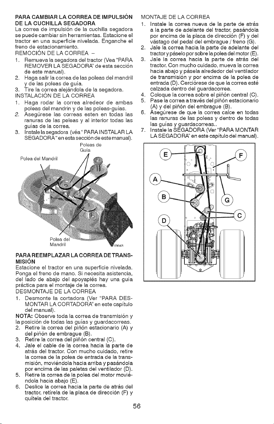
PARA CAMBIAR LA CORREA DE IMPULSION
DE LA CUCHILLA SEGADORA
La correa de impulsi6n de la cuchilla segadora
se puede cambiar sin herramientas. Estacione el
tractor en una superficie nivelada. Enganche el
freno de estacionamiento.
REMOCI6N DE LA CORREA -
1. Remueva la segadora del tractor (Vea"PARA
REMOVER LA SEGADORAI' de esta secciSn
de este manual).
2. Haga salir la correa de las poleas del mandril
y de las poleas de guia.
3. Tire la correa alej&ndola de la segadora.
INSTALACION DE LA CORREA
1. Haga rodar la correa alredeor de ambas
poleas del mandrin y de las poleas-guias.
2. AsegQrese las correas esten en todas las
ranuras de las peleas y al interior todas las
guias de la correa.
3. Instale la segadora (vea" PARA INSTALAR LA
S EGADORA" en esta secciSn de este manual).
Poleasde
Guia
Polea del Mandril
Polea de
Mandril
PARA REEM PLAZAR LA CORREA DE TRANS-
MISldN
Estacione el tractor en una superficie nivelada.
Ponga el freno de mano. Si necesita asistencia,
del lado de abajo del apoyapies hay una guia
pr&ctica para el montaje de la correa.
DESMONTAJE DE LA CORREA
1. Desmonte la cortadora (Ver "PARA DES-
MONTAR LA CORTADORAI' en este capitulo
del manual).
NOTA: Observe toda la correa de transmisi6n y
la posici6n de todas las guias y guardacorreas.
2. Retire la correa del pi56n estacionario (A) y
del pi56n de embrague (B).
3. Retire la correa del pi56n central (C).
4. Jale el cable de la correa hacia la parte de
atr&s del tractor. Con mucho cuidado, retire
la correa de la polea de entrada de la trans-
misi6n, moviendola hacia arriba y pas&ndola
por encima de las paletas del ventilador (D).
5. Retire la correa de la polea del motor movie-
ndola hacia abajo (E).
6. Deslice la correa hacia la parte de atr&s del
tractor, retirela de la placa de direcci6n (F) y
quitela del tractor.
56
MONTAJE DE LA CORREA
1. Instale la correa nueva de la parte de atr&s
a la parte de adelante del tractor, pas&ndola
por encima de la placa de direcci6n (F) y del
v&stago del pedal del embrague / freno (G).
2. Jale la correa hacia la parte de adelante del
tractor y p&selo por sobre la polea del motor (E).
3. Jale la correa hacia la parte de atr&s del
tractor. Con mucho cuidado, mueva la correa
hacia abajo y p&sela alrededor del ventilador
de transmisi6n y por encima de la polea de
entrada (D). Cerci6rese de que la correa este
calzada dentro del guardacorrea.
4. Coloque la correa sobre el pi56n central (C).
5. Pase la correa a traves del pi56n estacionario
(A) y del pi56n del embrague (B).
6. Aseg5rese de que la correa calce en todas
las ranuras de las poleas y dentro de todas
las guias y guardacorreas..
7. Instale la SEGADORA (Ver"PARA MONTAR
LA SEGADOR,_' en este capitulo del manual).
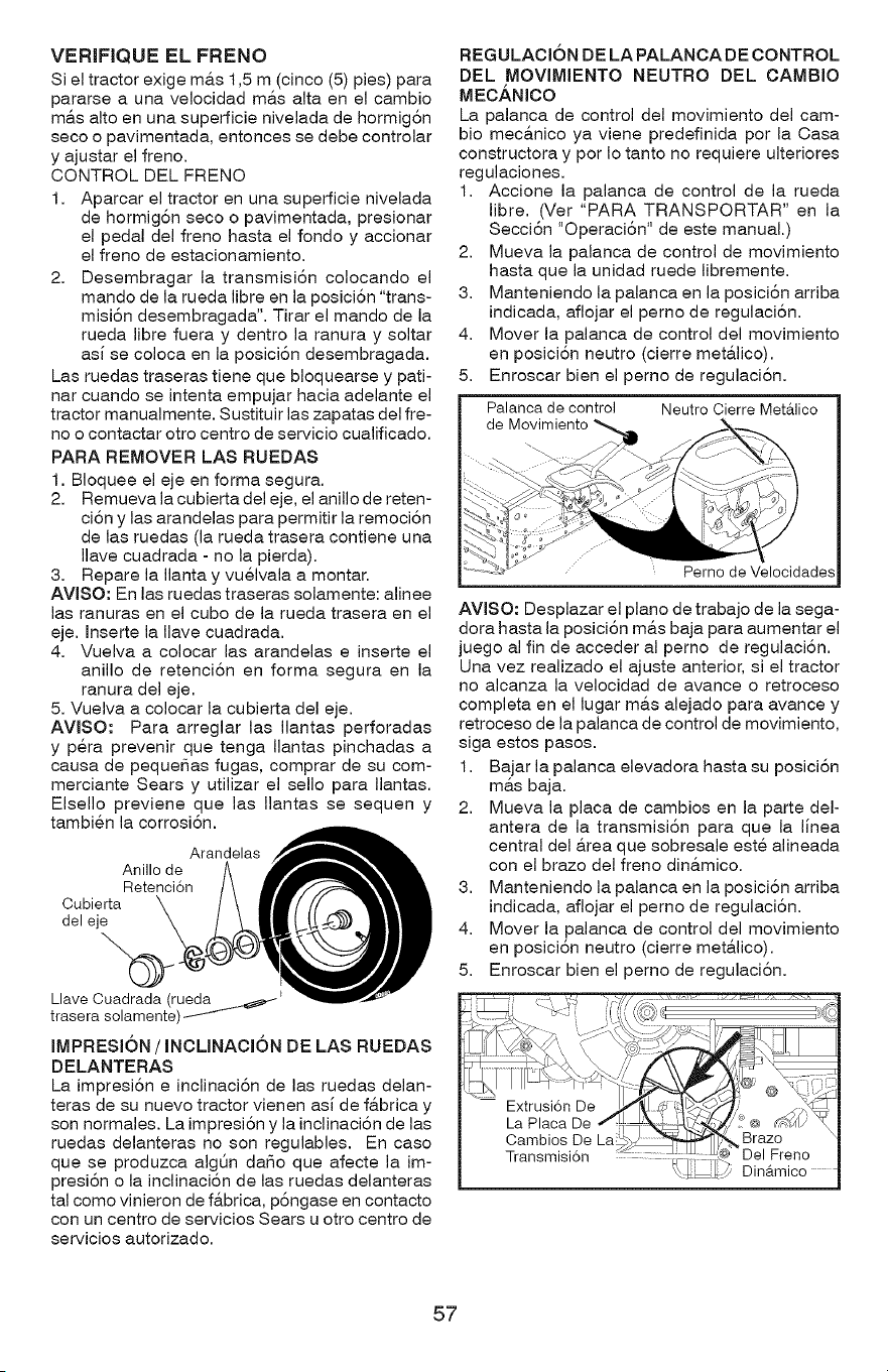
VERIFIQUEELFRENO
Siel tractor exige ma.s 1,5 m (cinco (5) pies) para
pararse a una velocidad m&s alta en el cambio
m&s alto en una superficie nivelada de hormig6n
seco o pavimentada, entonces se debe controlar
y ajustar el freno.
CONTROL DEL FRENO
1. Aparcar el tractor en una superficie nivelada
de hormig6n seco o pavimentada, presionar
el pedal del freno hasta el fondo y accionar
el freno de estacionamiento.
2. Desembragar la transmisiSn colocando el
mando de la rueda libre en la posiciSn "trans-
misiSn desembragada". Tirar el mando de la
rueda libre fuera y dentro la ranura y soltar
asi se coloca en la posiciSn desembragada.
Las ruedas traseras tiene que bloquearse y pati-
nar cuando se intenta empujar hacia adelante el
tractor manualmente. Sustituir las zapatas del fie-
no o contactar otro centro de servicio cualificado.
PARA REMOVER LAS RUEDAS
1. Bloquee el eje en forma segura.
2. Remueva la cubierta del eje, el anillo de reten-
ciSn y las arandelas para permitir la remociSn
de las ruedas (la rueda trasera contiene una
Ilave cuadrada - no la pierda).
3. Repare la Ilanta y vuelvala a montar.
AVlSO: En las ruedas traseras solamente: alinee
las ranuras en el cubo de la rueda trasera en el
eje. Inserte la Ilave cuadrada.
4. Vuelva a colocar las arandelas e inserte el
anillo de retenciSn en forma segura en la
ranura del eje.
5. Vuelva a colocar la cubierta del eje.
AVlSO: Para arreglar las Ilantas perforadas
y pera prevenir que tenga Ilantas pinchadas a
causa de pequeSas fugas, comprar de su com-
merciante Sears y utilizar el sello para Ilantas.
Elsello previene que las Ilantas se sequen y
tambien la corrosiSn.
Arandelas
Anillo de
Retenci6n
Cubierta
del eje
Llave Cuadrada (rueda ....__
trasera solamente)
IMPRESI(')N / INCLINACION DE LAS RUEDAS
DELANTERAS
La impresi6n e inclinaci6n de las ruedas delan-
teras de su nuevo tractor vienen asi de f&brica y
son normales. La impresi6n y la inclinaci6n de las
ruedas delanteras no son regulables. En caso
que se produzca algt_n daSo que afecte la im-
presi6n o la inclinaci6n de las ruedas delanteras
tal como vinieron de f&brica, p6ngase en contacto
con un centro de servicios Sears u otro centro de
servicios autorizado.
REGULACION DE LA PALANCA DE CONTROL
DEL MOVIMIENTO NEUTRO DEL CAMBIO
MECANICO
La palanca de control del movimiento del cam-
bio mec&nico ya viene predefinida por la Casa
constructora y por Io tanto no requiere ulteriores
regulaciones.
1. Accione la palanca de control de la rueda
libre. (Ver "PARA TRANSPORTAR" en la
SecciSn "OperaciSn" de este manual.)
2. Mueva la palanca de control de movimiento
hasta que la unidad ruede libremente.
3. Manteniendo la palanca en la posiciSn arriba
indicada, aflojar el perno de regulaciSn.
4. Mover la palanca de control del movimiento
en posiciSn neutro (cierre met&lico).
5. Enroscar bien el perno de regulaciSn.
Palanca de control Neutro Cierre Met&lico
de
Perno de Velocidades
AVISO: Desplazar el piano de trabajo de la sega-
dora hasta la posici6n m&s baja para aumentar el
juego al fin de acceder al perno de regulaci6n.
Una vez realizado el ajuste anterior, si el tractor
no alcanza la velocidad de avance o retroceso
completa en el lugar m&s alejado para avance y
retroceso de la palanca de control de movimiento,
siga estos pasos.
1. Bajar la palanca elevadora hasta su posici6n
m&s baja.
2. Mueva la placa de cambios en la parte del-
antera de la transmisi6n para que la linea
central del &rea que sobresale este alineada
con el brazo del freno din&mico.
3. Manteniendo la palanca en la posici6n arriba
indicada, aflojar el perno de regulaci6n.
4. Mover la palanca de control del movimiento
en posici6n neutro (cierre met&lico).
5. Enroscar bien el perno de regulaci6n.
57
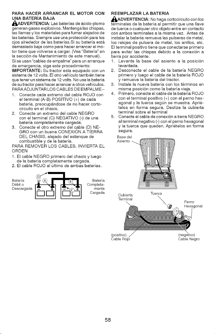
PARA HACER ARRANCAR EL MOTOR CON
UNA BATERiA BAJA
A(_ADVERTENCIA: Las baterias de &cido-plomo
generan gases explosivos. Mantenga las chispas,
las llamas y los materiales para fumar alejados de
las baterias. Siempre use una protecciSn para los
ojos alrededor de las baterias.Si su bateria est,.
demasiado baja como para hacer arrancar el mo-
tor tiene que volverse a cargar. (Yea "Bateria" en
la secci6n de Mantenimiento de este manual).
Si se usan "cables de empalme" para un arranque
de emergencia, siga este procedimiento:
IMPORTANTE: Su tractor esta equipado con un
sistema de 12 volts. El otro veh iculo tambien tiene
que tener un sistema de 12 volts. No use la bateria
de su tractor para hacer arrancar a otros vehiculos.
PARAADJ UNTAR LOS CABLES DE EMPALME-
1. Conecte cada extremo del cable ROJO con
el terminal (A-B) POSITIVO (+) de cada
bateria, preocup&ndose de no hacer corto-
circuito en el chasis.
2. Conecte un extremo del cable NEGRO
con el terminal (C) NEGATIVO (-) de una
bateria completamente cargada.
3. Conecte el otro extremo del cable (D) NE-
GRO con un buena CONEXION A TIERRA
DEL CHASIS, alejado del estanque de
combustible y de la bateria.
PARA REMOVER LOS CABLES, INVIERTA EL
ORDEN
1. El cable NEGRO primero del chasis y luego
de la bateria completamente cargada.
2. El cable ROJO al Qltimo de ambas baterias.
tr tr
Debil o Completa-
Descargada mente
Cargada
REEMPLAZAR LA BATERIA
_ADVERTENCIA: No haga cortocircuito con los
terminales de la bateria al permitir que una Ilave
de tuerca o cualquier otro objeto entre en contacto
con ambos terminales a la misma vez. Antes de
instalar la bateria remueva las pulseras de metal,
los relojes de pulsera de metal, los anillos, etc.
El terminal positivo tiene que conectarse primero
para evitar las chispas debido a la conexi6n a
tierra por accidente.
1. Levante la base del asiento a la posici6n
levantada.
2. Desconecte el cable de la bateria NEGRO
primero y luego el cable de la bateria ROJO
y remueva la bateria del tractor.
3. Instale la nueva bateria con los terminos en
misma posici6n como la bateria vieja.
4. Primero, conecte el cable de la bateria ROJO
con el terminal positivo (+) con el perno hex-
agonal y la tuerca segQn se muestra. Aprie-
telos en forma segura. Deslize la cubierta
terminal sobre el terminal
5. Conecte el cable de conexi6n a tierra NEGRO
al terminal negativo (-) con el perno hexagonal
y la tuerca que queden. Aprietelos en forma
segura.
Base del
Asiento
Cubierta Tuerca
Terminal _.
Pemo
)nal
(positivo)
Cable Rojo
(negative)
Cable Negro
58
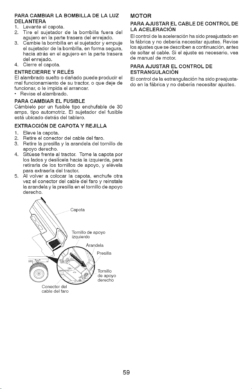
PARA CAMBIAR LA BOMBILLA DE LA LUZ
DELANTERA
1. Levante el capota.
2. Tire el sujetador de la bombilla fuera del
agujero en la parte trasera del enrejado.
3. Cambie la bombilla en el sujetador y empuje
el sujetador de la bombilla, en forma segura,
hacia atra.s en el agujero en la parte trasera
del enrejado.
4. Cierre el capota.
ENTRECIERRE Y RELES
El alambrado suelto o daSado puede producir el
real funcionamiento de su tractor, o que deje de
funcionar, o le impida el arrancar.
• Revise el alambrado.
PARA CAMBIAR EL FUSIBLE
C&mbielo por un fusible tipo enchufable de 30
amps, tipo automotriz. El sujetador del fusible
est& ubicado detr&s del tablero.
EXTRACCI6N DE CAPOTA Y REJILLA
1. Eleve la capota.
2. Retire el conector del cable del faro.
3. Retire la presilla y la arandela del tomillo de
apoyo derecho.
4. SitQese frente al tractor. Tome la capota por
los lados y deslicela hacia la izquierda, para
retirarla de los tomillos de apoyo, y elevela
para extraerla del tractor.
5. AI volver a colocar la capota, enchufe otra
vez el conector del cable del faro y reinstale
la arandela y la presilla en el tomillo de apoyo
derecho.
MOTOR
PARA AJUSTAR EL CABLE DE CONTROL DE
LA ACELERACION
El control de la aceleraci6n ha sido preajustado en
la f&brica y no deberia necesitar ajustes. Revise
los ajustes que se describen a continuaci6n, antes
de soltar el cable. Si el ajuste es necesario, vea
de manual de motor.
PARA AJUSTAR EL CONTROL DE
ESTRANGULACI6N
El control de la estrangulaci6n ha sido preajusta-
do en la f&brica y no deberia necesitar ajustes.
Capota
\\\\\\
Tornillo de apoyo
izquierdo
Arandela
Presilla
Conector del
cable del faro
Torniilo
de apoyo
derecho
59
Inmediatamente prepare su tractor para el alma-
cenamiento al final de la temporada o si el tractor
_ADVERTENCJA: Nunca almacene el tractor
con gasolina en el estanque dentro de un edificio
en donde losgases pueden alcanzaruna llama
expuestao una chispa.Permitaque elmotor se
enfrieantes de almacenarloen cualquierrecinto
privado.
TRACTOR
Remueva lasegadora deltractorpara elalma-
cenamiento por elinvierno.Cuando lasegadora
se va a almacenar por ciertoperiodode tiempo,
limpielacuidadosamente, quitetoda la mugre,
lagrasa, lashojas,etc.Gu&rdela en una &tea
limpiay seca.
I. Limpie todo eltractor(vea "LJMPIEZ,_'en la
secci6nde Mantenimientoen este manual).
2. Inspeccione y cambie las correas, si es nece-
sario (yea las instrucciones para el cambio de
las correas en la secci6n de Servicio y Ajustes
de este manual).
3. Lubriquelo, seg_n se muestra en la secci6n
de Mantenimiento de este manual.
4. Aseg5rese que todas las tuercas, los pernos y
los tornillos esten sujetados en forma segura.
Inspeccione las pares movibles para verificar
si hay daSo, rotura o desgaste. C&mbielas si
es necesario.
5. Retoque todas superficies pintadas oxidadas
o picadas; aplique lija antes de pintar.
BATERJA
• Cargue la bateria completamente antes de
guardarla.
• Despu@s de cierto periodo de tiempo en alma-
cenamiento, la bateria puede necesitar volver
a cargarse.
• Para ayudar a evitar la corrosi6n y las fugas
de potencia durante largos periodos de alma-
cenamiento, se deben desconectar los cables
de la bateria y se debe limpiar cuidad,osamen-
te (vea "PARA LIMPIAR LA BATERIA Y LOS
TERMJNALES" en la secci6n de Mantenimien-
tode este manual).
• Despues de limpiarla, deje los cables desco-
nectados y p6ngalos en donde no puedan
entrar en contacto con los terminales de la
bateria.
• Si se remueve la bateria del tractor para el
almacenamiento, no la guarde directamente
sobre concreto o sobre superficies hQmedas.
• Si la unidad est& equipada con indicador de
bateria/conector de carga, se puede adquirir
una unidad de carga opcional y conectarse a la
unidad para cargar la bateria durante un alma-
cenamiento prolongado. Jnspeccione y limpie
las terminales de la bateria conforme sea
necesario antes de almacenarse durante un
tiempo prolongado con el cargador conectado.
MOTOR
SISTEMA DE COMBUSTIBLE
IMPORTANTE: Es important evitar que se
forman depositos de goma en partes funda-
mentales del sistema de combus-tible tales
como el carburador, el filtro del combustible,
la manguera del combustibles mezclados con
alcohol (conocido como gasohol o que tienen
etanol o metanol) pueden atraer humedad, Io
que conduce a la separaci6n y a la formaci6n
de acudos durante elalmacenamiento. La gaso-
lina acidica puede daSar el sistema de combus-
tible de un motor durante el periodo de almace-
namiento.
• Vaciar el dep6sito del carburante poniendo en
marcha el motor y dej&ndolo funcionar hasta
que el carburante termine el carburador est@
vacio.
• Nunca use los productos para limpieza del
carburador o del motor en el estanque de
combustible pues se pueden producir daSos
permanentes.
• Use combustible nuevo la pr6ximatemporada.
AVlSO: El estabilizador de combustible es una
alternativa aceptable para reducir a un minimo
la formaci6n de dep6sitos de goma en el com-
bustible durante el periodo de almacenamiento.
Agregue estabilizador a la gasolina en el es-
tanque de combustible o en el envase para el
almacenamiento. Siempre siga la proporci6n de
mezcla que se encuentra en el envase del estabi-
lizador. Haga funcionar el motor por Io menos 10
minutos despues de agregar el estabilizador, para
permitir que este Ilegue al carburador. No vaciar la
gasolina del estanque de gasolina y el carburador
si se est& usando estabilizador de combustible.
AOEJTE DEL MOTOR
Drene el aceite (con el motor caliente) y c&mbielo
con aceite de motor limpio. (Vea "MOTOR" en
la secci6n de Mantenimiento" de este manual.)
ClLINDRO(S)
1. Remueva la(s) bujia(s).
2. Vacie 29.5 mL (1 Oz.) de aceite a traves del
agujero(s) de la bujia en el cilindro(s).
3. Gire la Ilave de ignici6n a la posici6n de
"ARRANQUE" (START), por unos cuantos
segundos para distribuir el aceite.
4. Cambie por bujia(s) nueva(s).
OTROS
• No guarde la gasolina de una temporada a la
otra.
• Cambie el envase de la gasolina si se emp-
ieza a oxidar. La oxidaci6n y/o la mugre en su
gasolina producir&n problemas.
• Si es posible, guarde su unidad en un recinto
cerrado y cQbrala para protegerla contra el
polvo y la mugre.
• Cubra su unidad con un forro protector ad-
ecuado que no retenga la humedad. No use
pla.stico. El pl&stico no puede respirar, Io que
permite la formaci6n de condensaci6n, Io que
producir& la oxidaci6n de su unidad.
IMPORTANTE: Nunca cubra el tractor mientras
el motor y las &teas de escape todavia est&n
calientes.
60
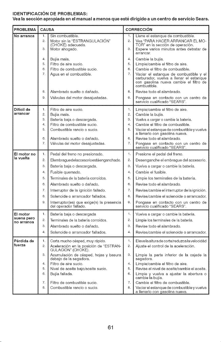
IDENTIFICACION DE PROBLEMAS:
Yea la secci6n apropiada en el manual a menos que este dirigido a un centto de servicio Seats.
PROBLEMA
NO arraRca
Dificil de
arrancar
El motor no
la vuelta
El motor
sueRa pero
nO arranca
P_rdida de
fuerza
CAUSA
1.
2.
3.
4.
5.
6.
7.
8.
9.
1.
2.
3.
4.
5.
1.
2.
3.
4.
5.
6.
7.
8.
9.
1.
2.
3.
4.
1.
2.
3.
4.
5.
6.
7.
8.
Sin combustible.
Motor sin la "ESTRANGULACION"
(CHOKE) adecuada.
Motor ahogado.
Bujia mala.
Filtro de aire sucio.
Filtro de combustible sucio.
Agua en el combustible.
Alambrado suelto o daSado.
i Va.lvulas del motor desajustadas.
Filtro de aire sucio.
Bujia mala.
Bateria baja o descargada.
Filtro de combustible sucio.
Combustible rancio o sucio.
Alambrado suelto o daSado.
Va.lvuiasdel motor desajustadas.
Pedal del freno no presionado.
Elembraguedelaccesorioest&enganchado.
Bateria baja o descargada.
Fusible quemado.
Terminales de la bateria corroidos.
Alambrado suelto o daSado.
Interruptor de la ignici6n fallado.
Solenoide o arrancador fallados.
Interruptor(es) que exige(n) la presencia
del operador fallado.
Bateria baja o descargada
Terminales de la bateria corroidos.
Alambrado suelto o daSado.
Solenoide o arrancador fallados.
Corta mucho c@sped, muy r_.pido.
Aceleraci6n en la posici6n de "ESTRAN-
GULACION" (CHOKE).
Acumulaci6n de c@sped, hojas y basura
debajo de la segadora.
Filtro de aire sucio.
Nivel de aceite bajo/aceite sucio.
Bujia fallada.
Filtro de combustible sucio.
Combustible rancio o sucio.
CORRECCION
1. Llene el estanque de combustible.
2. Vea"PARA HACER ARRANCAR EL MO-
TOR" en la secci6n de operaci6n.
3. Espere varios minutos antes detratar de
arrancar.
4. Oambie la bujia.
5. Limpie/cambie el filtro de aire.
6. Cambie el filtro de combustible.
7. Vaciar el estanque de combustible y el
carburador, vuelva a Ilenar el estanque
con gasolina nueva cambie el filtro de
combustible.
8. Revise todo el alambrado.
9. Pongase en contacto con un centro de
servicio cualificado "SEARS".
1. Limpie/cambie el filtro de aire.
2. Oambie la bujia.
3. Vuelva a cargar o cambie la bateria.
4. Cambie el filtro de combustible.
5. Vaciar el estanque de combustible y vuelva
a Ilenarlo con gasolina nueva.
6. Revise todo el alambrado.
7. Pongase en contacto con un centro de
servicio cualificado "SEARS".
1. Presione el pedal del freno.
2. Desengancheelembrague del accesorio.
3. Vuelva a cargar o cambie la bateria.
4. Cambie el fusible.
5. Limpie los terminales de la bateria.
6. Revise todo el alambrado.
7. Revise/cambie elinterruptor de laignici6n.
8. Revise/cambie el solenoide o arrancador.
9. Pongase en contacto con un centro de
servicio cualificado "SEARS".
1. Vuelva a cargar o cambie la bateria.
2. Limpie los terminales de la bateria.
3. Revise todo el alambrado.
4. Revise/cambie el solenoide o arrancador.
1. Eleve laalturade corte/reduzcalavelocid&d
2. Ajuste el control de la aceleraci6n.
3. Limpie la parte inferior de la cajade la
segadora.
4. Limpie/cambie el filtro de aire.
5. Revise el nivel de aceite/cambie el aceite.
6. Limpie y vuelva a ajustar la abertura o
cambie la bujia.
7. Cambie el filtro de combustible.
8. Vaciar el estanque de combustible y vuelva
a Ilenarlo con gasolina nueva.
61
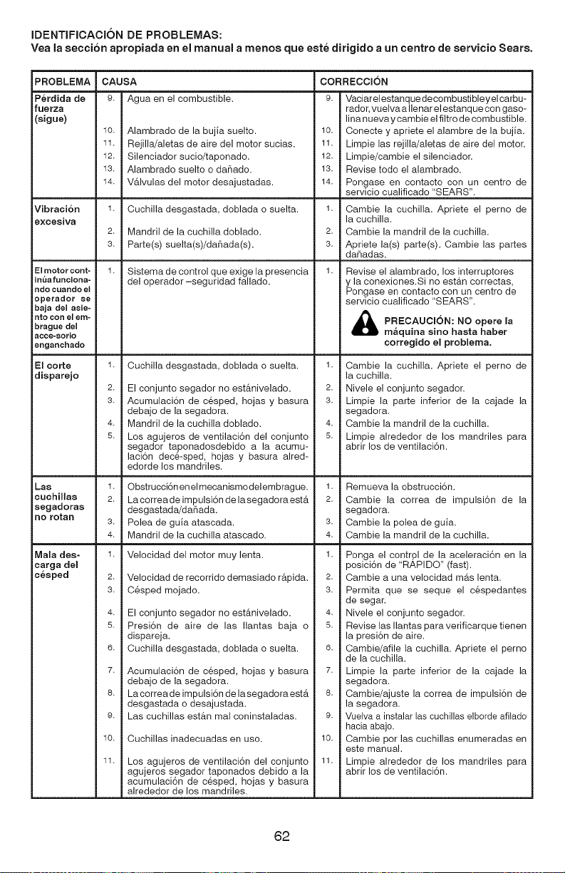
IDENTIFICACION DE PROBLEMAS:
Yea la secci6n apropiada en el manual a menos que este dirigido a un centro de servicio Sears.
PROBLEMA CAUSA CORRECCmON
P_rdida de 9. Agua en el combustible, 9. Vaciarelestanquedecombustibleyelcarbu-
fuerza rador, vuelvaallenar el estanque con gaso-
(sigue) lina nueva y cambie el filtro de combustible.
10. Alambrado de la bujia suelto. 10. Conecte y apriete el alambre de la bujia.
11. Rejilla/aletas de aire del motor sucias. 11. Limpie las rejilla/aletas de aire del motor.
12. Silenciador sucio/taponado. 12. Limpie/cambie el silenciador.
13. Alambrado suelto o dar_ado. 13. Revise todo el alambrado.
14. V&lvulas del motor desajustadas. 14. Pongase en contacto con un centro de
servicio cualificado "SEARS".
Vibracion 1. Cuchilla desgastada, doblada o suelta. 1. Cambie la cuchilla. Apriete el perno de
excesiva la cuchilla.
2. Mandril de la cuchilla doblado. 2. Cambie la mandril de la cuchilla.
3. Parte(s) suelta(s)/da_ada(s). 3. Apriete la(s) parte(s). Cambie las partes
dar_adas.
El motor cont-
inua funciona-
ndo cuando el
operador se
baja del asie-
nto con el em-
brague del
acce-8orio
enganchado
Sistema de control que exige la presencia
del operador-seguridad fallado.
Revise el alambrado, los interruptores
y la conexiones.Si no est&n correctas,
Pongase en contacto con un centro de
servicio cualificado "SEARS".
PRECAUCION: NO ma
opere
m&quina sino hasta haber
corregido el problema.
El eorte
disparejo
1.
2.
3.
4.
5.
Cuchilla desgastada, doblada o suelta.
El conjunto segador no est&nivelado.
Acumulaci6n de cesped, hojas y basura
debajo de la segadora.
Mandril de la cuchilla doblado.
Los agujeros de ventilaciSn del conjunto
segador taponadosdebido a la acumu-
laci6n dec6-sped, hojas y basura alred-
edorde los mandriles.
1. Cambie la cuchilla. Apriete el perno de
la cuchilla.
2. Nivele el conjunto segador.
3. Limpie la parte inferior de la cajade la
segadora.
4. Cambie la mandril de la cuchilla.
5. Limpie alrededor de los mandriles para
abrir los de ventilaciSn.
Las
cuehillas
segadoras
no rotan
1. Obstrucci6n enel mecanismodelembrague.
2. La correade impulsi6n de lasegadora est&
desgastada/daSada.
3. Polea de guia atascada.
4. Mandril de la cuchilla atascado.
1. Remueva la obstrucci6n.
2. Cambie la correa de impulsi6n de la
segadora.
3. Cambie la polea de guia.
4. Cambie la mandril de la cuchilla.
Mala des-
carga del
cesped
1.
2.
3.
4.
5.
6.
7.
8.
9.
10.
11.
Velocidad del motor muy lenta.
Velocidad de recorrido demasiado r&pida.
C6sped mojado.
El conjunto segador no est&nivelado.
Presi6n de aire de las Ilantas baja o
dispareja.
Cuchilla desgastada, doblada o suelta.
Acumulaci6n de cesped, hojas y basura
debajo de la segadora.
La correade impulsi6n de lasegadora est&
desgastada o desajustada.
Las cuchillas est&n mal coninstaladas.
Cuchillas inadecuadas en uso.
Los agujeros de ventilaci6n del conjunto
agujeros segador taponados debido a la
acumulaci6n de cesped, hojas y basura
alrededor de los mandriles.
1. Ponga el control de la aceleraci6n en la
posici6n de "RAPIDO" (fast).
2. Cambie a una velocidad ma.s lenta.
3. Permita que se seque el c_spedantes
de segar.
4. Nivele el conjunto segador.
5. Revise las Ilantas para verificarque tienen
la presi6n de aire.
6. Cambie/afile la cuchilla. Apriete el perno
de la cuchilla.
7. Limpie la parte inferior de la cajade la
segadora.
8. Cambie/ajuste la correa de impulsi6n de
la segadora.
9. Vuelva a instalar las cuchillas elborde afitado
hacia abajo.
10. Cambie por las cuchillas enumeradas en
este manual.
11. Limpie alrededor de los mandriles para
abrir los de ventilaci6n.
62
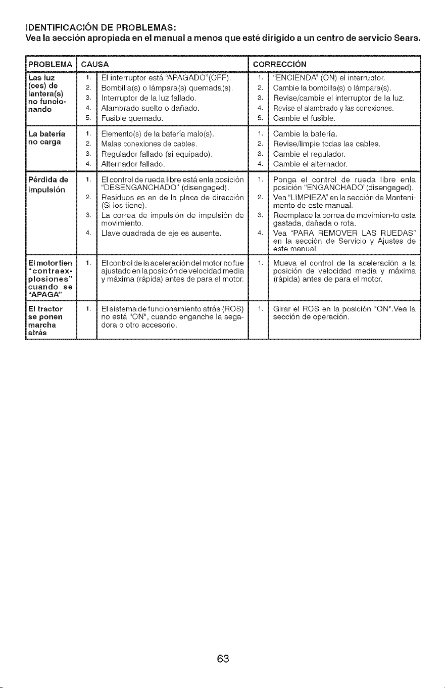
IDENTIFICACION DE PROBLEMAS:
Yea la secci6n apropiada en el manual a menos que este dirigido a un centro de servicio Seats.
PROBLEMA
(ces) de
lantera(s)
no funcio-
nando
La bateria
no carga
P_rdida de
impulsi6n
El motor tien
"contrae×-
)moaiones"
cuando se
"APAGA"
El tractor
se porter
marcha
atr_s
CAUSA
2. Bombilla(s) o I_tmpara(s) quemada(s).
3. Interruptor de la luz fallado.
4. Alambrado suelto o daSado.
5. Fusible quemado.
1. Elemento(s) de la bateria male(s).
2. Malas conexiones de cables.
3. Regulador fallado (si equipado).
4. Alternador fallado.
1. El control de rueda libre esta enla posici6n
"DESENGANCHADO" (disengaged).
2. Residuos es en de la placa de direcci6n
(Si los tiene).
3. La correa de impulsi6n de impulsi6n de
movimiento.
4. Llave cuadrada de eje es ausente.
El control de la aceleraci6n del motor no fue
ajustado en la posici6n de velocidad media
y m&xima (r&pida) antes de para el motor.
El sistema de funcionamiento atr&s (ROS)
no est& "ON", cuando enganche la sega-
dora o otro accesorio.
CORRECCION
2. Cambie la bombilla(s) o lampara(s).
3. Revise/cambie el interruptor de la luz.
4. Revise el alambrado y las conexiones.
5. Cambie el fusible.
1. Cambie la bateria.
2. Revise/limpie todas las cables.
3. Cambie el regulador.
4. Cambie el alternador.
1. Ponga el control de rueda libre enla
posici6n "ENGANCHADO"(disengaged).
2. Vea"LIMPIEZ,_' en la secci6n de Manteni-
mento de este manual.
3. Reemplace la correade movimien-to esta
gastada, daSada o rota.
4. Vea "PARA REMOVER LAS RUEDAS"
en la secci6n de Servicio y Ajustes de
este manual.
1. Mueva el control de la aceleraci6n a la
posici6n de velocidad media y m&xima
(r&pida) antes de para el motor.
1. Girar el ROS en la posici6n "ON".Vea la
secci6n de operaci6n.
63
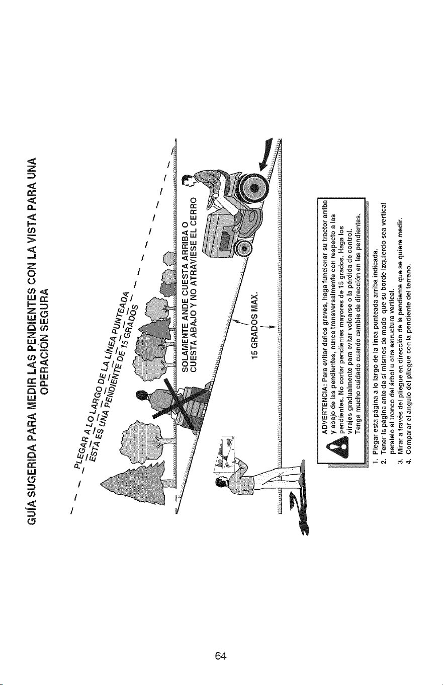
GUiASUGERIDAPARA MEDIR LAS PENDIENTES CON LA VISTA PARA UNA
OPERACION SEGURA
Ob
4_
_ DVERTENCIA: Para evitar daSos graves, haga funcionar su tractor arriba
y abajo de las pendientes, nunca transversalmente con respecto a las
pendientes. No cortar pendientes mayores de 15 grados. Haga los
virajes gradualmente para evitar volcarse o la p_rdida de control.
Tenga macho cuidado cuando cambie de direccibn en las pendientes.
1. Plegar esta pagina a Io largo de la linea panteada arriba indicada.
2. Tenet la pagina ante de si mismos de modo que su borde izquierdo sea vertical
paralelo al tronco del arbol u otra estructura vertical.
3. Mirar a traves del pliegue en direccibn de la pendiente que se quiere medir.
4. Comparar el angulo del pliegue con la pendiente del terreno.

65

66

67

CRAFrSMAN°
Product questions or problems?
1-888-331-4569
Customer Care Hot Line
Get answers to questions, troubleshoot problems,
order parts, or schedule repair service.
Pars respuestas a preguntas o probtemas, y ordenar
piezas o pedir servicio para Ia reparacidn de su equipo.
To help us help you, register your product at www.craftsman.com/registration
Pars poderte ayudar mejor, registra tu producto en www.craftsman.com/registration
i
i! Join the Craftsman Club today!
www.craftsman.com/signup
Receive exclusive member benefits including special pricing and offers,
projects.ari.g, expe_tadvi_e0a.d SHOPYOURWAYREWARDS_
Como miembro exclusivo, recibe diversos beneficios como ofertas, precios especiales, proyectos
_u_vos,oonsejosd_ e×pe_tosy n_est_op_og_amad_ pontosSHOPYOURWAYREWARDS!
(R)Registered Trademark / T_ Trademark of KCD IP, LLC in the United States. or Sears Brands. LLC in other countries
(R_Marca Registrada / TM Marca de F&brica de KCD IP. LLC en Estados Unidos. o Sears Brands, LLC in otros paises
02.24.14 AP Printed in the U.S.A.
