
L BER 917.259547
OWNER'S MANUAL
• Assembly
o Operation
®Customer Responsibilities
o Service and Adjustments
. Repair Parts
For answers to your questions
about this product, Call:
1-800-659-5917
Sears Craftsman Help Line
5 am o5 pm, Mon - Sat
CAUTION: Read and follow all safety rules and instructions before operating this equipment.
mUlllllllllll IIII IIIII
SAFETY RULES
Safe Operation Practices for Ride-On Mowers
IMPORTANT: THIS CUTTING MACHINE IS CAPABLE OF AMPUTATING HANDS AND FEET AND THROWING OBJECTS.
FAILURE TO OBSERVE THE FOLLOWING SAFETY INSTRUCTIONS COULD RESULT IN SERIOUS INJURY OR DEATH.
i. GENERAL OPERATION
• Read, understand, and follow all instructions in the manual
and on the machine before starting,
• Only allow responsible adults, who are familiar with the
instructions, to operate the machine.
• Clear the area of objects such as rocks, toys, wire, etc.,
which could be picked up and thrown by the blade.,
• Be sure the area is clear of other peoplebeforemowing. Stop
machine if anyone enters the area.
• Never carry passengers.,
• Do notmow in reverse unless absolutelynecessary. Always
look down and behind before and while backing°
• Be aware of the mower discharge directionand do notpoint
it at anyone. Do not operate the mower withouteither the
entire grass catcher or the guard in place.
• Slow down before turning,
, Never leave a running machine unattended, Always turn off
blades, set parking brake, stop engine, and remove keys
before dismounting
° Turn off blades when not mowing,
• Stop engine before removing grass catcher or unclogging
chute.
• Mow only in daylight or good artificial light.
• Do not operate the machine while under the influence of
alcohol or drugs.
• Watch for traffic when operating near or crossingroadways.
° Use extra care when loading or unloadingthe machine into
a trailer or truck,
I1. SLOPE OPERATION
Slopes are a major factor related to loss-of-control and
tipover accidents; which can result in severe injury or death.
All slopes require extra caution, tf you cannot back up the
slope or if you feel uneasy on it, do not mow it_
DO:
• Mow up and down slopes, not across..
• Remove obstacles such as rocks, tree limbs, etc.
• Watch for holes, ruts, or bumps. Uneven terrain could
overturn the machine, Ta// grass can hide obstac/es_
• Use slow speed. Choose a !ow gear sothat you will nothave
to stop or shift while on the slope..
• Follow the manufacturer's recommendations for wheel
weights or'counterweights to improve stability..
• Use extra care with grass catchers or other attachments.
These can change the stability of the machine,,
° Keep all movement on the slopes s/owand gradual Do not
make sudden changes in speed or direction.
° Avoid starting or stopping on a slope, if tires lose traction,
disengage the blades and proceed s!owly straight down the
slope.,
DO NOT:
° Do not turnon slopes unlessnecessary, and then,turnslowly
and gradually downhill, if possible.,
° Do not mow near drop-offs, ditches, or' embankments, The
mower could suddenly turn over if a wheel is over the edge
of a cliff or ditch, or if an edge caves in.
• Do not mow on wet grass. Reduced traction could cause
sliding_
• Do not try to stabilize the machine by puttingyour foot on the
ground,
= Do not use grass catcher on steep slopes,.
2
!11. CHILDREN
Tragic accidents can occur if the operator is not alert to the
presence of children. Children are often attracted to the
machine and the mowing activity. Never' assume that
children will remain where you last saw them.
• Keep children out of the mowing area and under the watchful
care of another responsible adult.
° Be alert and turn machine off if children enter the area.
• Before and when backing, look behind and down for small
children,
• Never carry children. They may fall off and be seriously
injured or interfere with safe machine operation.
• Never allow children to operate the machine.
• Use extra care when approaching blind corners, shrubs,
trees, or other objects that may obscure vision_
IV.
e
e
O
°
e
°
o
°
°
SERVICE
Use extra care inhandlinggasoline and other fuels. They are
flammable and vapors are explosive°
Use only an approved container.
Never remove gas cap or add fuel with the engine
running. Allow engine to cool before refueling, Do not
smoke_
Never refuel the machine indoors.
Never store the machine or fuel container inside where
there is an open flame, such as a water heater.
Never run a machine inside a closed area.
Keep nuts and bolts, especially blade attachment bolts, tight
and keep equipment in good condition.,
Never tamper with safety devices. Check their proper
operation regulady_
Keep machine free of grass, leaves, or other debris build-up.
Clean oil or fuel spillage. Allow machine to cool before
storing°
Stop and inspect the equipment if you strike an object..
Repair, if necessary, before restarting.
Never make adjustments or repairs with the engine running.
Grass catcher componentsare subject towear, damage, and
deterioration, which could expose moving parts or allow
objects to be thrown, Frequently check components and
replace with manufacturer's recommended parts, when nec-
essary_
Mower blades are sharp and can cuL Wrap the blade(s) or
wear gloves, and use extra caution when servicing them,.
Check brake operation frequently. Adjust and service as
required.
II II iii,
_b Look for this symbol to point out im-
portant safety precautions. It means
CAUTION!t_ BECOMEALERTlt! YOUR
SAFETY IS INVOLVED.
HI, ,,,,,,,, ,,,,,,,,,,,,,,,,,,,,,,, ,, ,,,,,,,,,,,,,,,,,,,,,,,
CAUTION: Always disconnect spark plug
wire and placewire where it cannot contact
spark plug in order to prevent accidental
starting when setting up, transporting,
adjusting or making repairs.
WARNING A
The engine exhaust from this product con-
tains ctiemicals known to the State of Califor-
nia to cause cancer, birth defects, or other
reproductive harm.

CONGRATULATIONS on your purchase of a Sears
Tractor. it has been designed, engineered and manufac-
tured to give you the best possible dependability and
performance.
Should you experience any problem you cannot easily
remedy, please contact your nearest Sears Authorized
Service CenteriDepartment_ We have competent, well-
trained technicians and the proper tools to service or repair
this tractor°
Please read and retain this manual° The instructions will
enable you to assemble and maintain your tractor properly..
Always observe the "SAFETY RULES"°
MODEL
NUMBER 917259547
SERIAL
NUMBER
DATE OF PURCHASE
THE MODEL AND SERIAL NUMBERS WILL BE FOUND
ON A PLATE UNDER THE SEAT°
YOU SHOULD RECORD BOTH SERIAL NUMBER AND
DATE OF PURCHASE AND KEEP IN A SAFE PLACE
FOR FUTURE REFERENCE°
MAINTENANCE AGREEMENT
A Sears Maintenance Agreement is available on this prod-
ucto Contact your nearest Sears store for details_
CUSTOMER RESPONSIBILITIES
. Read and observe the safety rules_
o Follow a regularschedule in maintaining, caring for and
using your tractor.
° Follow the instructions under "Customer Responsibili-
ties" and "Storage" sections of this owner's manual,
PRODUCT SPECIIFICATBONS
HORSEPOWER: 15.5
GASOLINE CAPACITY t,25 GALLONS
AND TYPE: UNLEADED REGULAR
OIL TYPE (API-SF/SGtSH): SAE 10W30 (above 32°F)
SAE 5W-30 (below 32=F)
OtL CAPACITY: W/FILTER: 4.0 PINTS
W/O FILTER: 3.5 PINTS
SPARK PLUG: CHAMPION RCI2YC
(GAP: .040")
VALVE CLEARANCE: NOT ADJUSTABLE
GROUND SPEED (MPH): FORWARD:
1st t ,,1
2nd 1o4
3rd 2,3
4th 3,5
5th 45
6th 5,7
REVERSE: 1.8
TIRE PRESSURE: FRONT: 14 PSi
REAR: 10 PSI
CHARGING SYSTEM: 3 AMPS BATTERY
5 AMPS HEADLIGHTS
BATTERY: AMP/HR: 30
MIN. CCA: 240
CASE SIZE: U1R
BLADE BOLT TORQUE: 27-35 FT,,LBS,
!
WARNING: This tractor is equipped with an internal
combustionengineand should not be used on or near any
unimproved forest-covered, brush-covered o{ grass-cov-
ered land unless the engine's exhaust system is equipped
with a spark arrester meeting applicable local or state laws
(if any). If a spark arrester is used, it should be maintained
ineffective working order by the operator°
In the state of California the above is required by law
(Section 4442 of the California Public Resources Code).
Other states may have similar laws,. Federal laws apply on
federal lands. A spark arrester for the muffler is available
through your nearest Sears Authorized Service Center!
Department (See REPAIR PARTS section of this manuai)o
_1_ III II IIIIIIl_l_lu_l_lj,l_l I I JIJJJllIJJ_ll _rl_l_ ± ± I , I ±± II1,,,,,I
LIMITED TWO YEAR WARRANTY ON cRAFTSMAN RIDING EQUIPMENT
For two (2) years from the date of purchase, if this Craftsman Riding Equipment is maintained, lubricated and tuned up according to
the instructions in the owner's manual, Sears will repair or replace, free of charge, any parts found to be defective in matedal or
workmanship.
This Warranty does not cover:
• Expendable items which become worn during normal use, such as blades, spark plugs, air cleaners, belts, etc.,
- Tire replacement or repair caused by punctures from outside objects, such as nails, thorns, stumps, or glass,,
o Repairs necessary because of operator abuse, negligence, improper storage or accident or the failure to maintain the
equipment according to the instructionscontained in the owner's manual,,
• Riding equipment used for commercial or rental purposes.
LIMITED 90 DAY WARRANTY ON BATTERY
For ninety (90) days from date of purchase, if any battery included with this dding equipment proves defective in material or
workmanship and our testing determines the battery will not hold a charge, Sears witl replace the battery at no charge.
IN-HOME WARRANTY SERVICE ON YOUR CRAFTSMAN RIDING EQUIPMENT IS AVAILABLE AT NO-CHARGE FOR 30 DAYS
FROM THE DATE OF PURCHASE.. PLEASE CONTACT YOUR NEAREST SERVICE CENTER. AFTER 30 DAYS FROM THE
DATE OF PURCHASE, WARRANTY SERVICE IS AVAILABLE BY TAKING YOUR CRAFTSMAN RIDING EQUIPMENT TO YOUR
NEAREST SEARS SERVICE CENTER. (IN-HOME WARRANTY SERVICE WILL STILL BE AVAILABLE AFTER 30 DAYS FROM
THE DATE OF PURCHASE BUT A STANDARD TRIP CHARGE WILL APPLY°) THIS WARRANTY APPLIES ONLY WHILE THIS
PRODUCT IS IN THE UNITED STATES
This Warranty gives you specific legal dghts, and you may also have other rights which may vary from state to state,,
SEARS, ROEBUCK AND CO., D/817 WA, HOFFMAN ESTATES, IL 60179
3
TABLE OF CONTENTS
SAFETY RULES ............................................................ 2
PRODUCT SPECIFICATIONS ...................................... 3
CUSTOMER RESPONSIBILITIES ..................... 3, 15-19
WARRANTY .................................................................. 3
TABLE OF CONTENTS ................................................ 4
ASSEMBLY ...'............................................................. 7-9
OPERATION ........................................................... 10-14
MAINTENANCE SCHEDULE ...................................... 15
SERVICE AND ADJUSTMENTS ............................ 20-25
STORAGE ................................................................... 26
TROUBLESHOOTING ............................................ 27-28
REPAIR PARTS - TRACTOR ................................. 30-47
REPAIR PARTS - ENGINE .................................... 48-53
PARTS ORDERING/SERVICE .................. BACK PAGE
INDEX
A
Accessories ...............................................5
Adjustments:
Brake ................................................................22
Carburetor ...................................................25
Mower:
Front-To-Back ...........................21
Side-To-Side .......................... 21
Throttle Control Cable ........................25
Air Filter, Engine .....................................................18
Air Screen, Engine ...........................................18
Assembly ........................................................7-9
B
Battery:
Charging .................................................7
Cleaning ..........................................16
Starting with Weak Battery ..........23
Storage ............................................................26
Terminals ............................................................16
Belts:
Motion Ddve
Removal/Replacement .......... 22
Mower Blade Drive
Removal/Replacement ..............22
Blade:
Sharpening ..........................................16
Replacement ....................................................16
Brake Adjustment ......................................................22
C
Carburetor Adjustment .......................................25
Controls, Tractor .....................................11
Customer Responsibilities ............ 15-19
Engine:
Air Filter'. .........................................18
Air Screen, Engine ..............................18
Battery ...........................................................17
Cooling Fins, Engine ................ 18
Engine Oil ..............................................17
Fuel Filter ....................................................19
Spark Plugs ...................................18
Tractor:
Blades ..........................................................16
Lubrication Chart ..................... 15
Maintenance Schedule .................15
Tire Care .........................................9,16,23
Cutting Height, Mower ......................................12
E
Electrical:
interlocks and Relays ...........................24
Schematic .............................................................29
Widng Diagram ............................ 30
Engine:
Air Filter .......................................................18
Air Screen ....................................................18
Cooling Fins, Engine .................................18
Oil Change .............................................17
Oil Level .....................................13,17
Oil Type ....................................................17
Preparation ................................................13
Repair Parts .......................................48-53
Starting.......................................................14
Storage ...............................................26
F
Filters:
Air .....................................................................18
Fuel ...............................................................19
Fuel:
Type ......................................................13
Storage ......................................................26
Fuse .....................................................................24
G
Gauge Wheels ............................................8
H
Hood Remova!!Installation ................. 24
L
Leveling Mower Deck ...............................2t
LubricationChart ....................................15
M
Maintenance Schedule .................................15
Mower:.
Adjustment, Front4o-Back ..................21
Adjustment, Side-to-Side ............ 21
Blade Sharpening ..........................16
Blade Replacement ..........................16
Cutting Height .............................................12
Installation .......................;.......................20
Operation ...................................................13
Removal .......................................................20
Mowing Tips ......................................................14
Muffler _...................................................................18
Spark Arrester .............................3,40
Mulcher Plate .....................................................9
O
Oil:
Cold Weather Conditions ....... 14, t7
Engine ..................................................17
Storage .....................................................26
Operation ........................................................10-14
Operating Mower ................................ 13
Options:
Accessodes ..........................................................5
Spark Arrester. ........................................... 3,40
P
Parking Brake ..........................................11-t2
Parts Bag ................................................ 6
Parts, Replacement/Repair ...............30-47
Product Specifications ............................ 3
R
Repair Parts ............................................................30-47
S
Safety Rules ........................................... 2
Seat ...............................................................8
Service and Adjustments ...................20-25
Brake ........................................... 22
Carburetor, ................................... 25
Fuse ................................................ 24
Hood Removal/Installation ............24
Motion Drive Belt
RemovaVReplacement ...................22
Mower Blade Drive Belt
Removal/Replacement ................22
Mower Adjustment:
Front-to-Back ......................... 2t
Side-to-Side .....................................2t
Mower Installation ...................................20
Mower Removal ..........................................20
Tire Care ............................. 9,16,23
Slope Guide Sheet ............................. 55
Spark Plugs ......................................... 18
Specifications ...........................................3
Starting the Engine ..................................13-14
Steering Wheel ..........................................................7,23
Stopping the Tractor ..............................12
Storage ......................................................26
T
Throttle Controt Cable Adjustment ......25
Tires ................................................................ 9,16,23
Trouble Shooting Chart ............................27-28
Transaxle Repair Parts .......................46-47
W
Warranty ..................................................................3
Wiring Diagram .................................. 30
Wiring Schematic ................................ 29
4

ACCESSORmES A ATTACHMENTS
These accessories and attachments were available throughmost Sears retailoutlets and service centers when the tractorwas purchased..
Most Sears stores can order these items for you when you provide the model number of your tractor,.
ENGINE MAINTENANCE
SPARK PLUG BLADES BELTSGAS CAN ENGINEOIL FUEL STABILIZER
AIR FILTER
%
PERFORMANCE
Sears offers a wide variety of attachmentsthat fit your tractor. Many of these are listedbelow with brief explanations of how they can help
you+ This listwas current at the time of publication;however, it may change in future years - more attachments may be added, changes
may be made in these attachments, or some may no longer be available or fit your model Contact your nearest Sears store for the
accessories and attachments that are available for your tractor,
Most of these attachments do not require additional hitches or conversion kits (those that do are indicated) and are designed for easy
attaching and detaching,
AERATOR promotes deep root growth tot a healthy lawn+ Ta-
pered 2+5+inch steel spikes mounted on 10-inch diameter discs
puncture holes in soit at close intervals to let moisture soak in+.
Steel weight tray for increased penetration..
BAGGER lets you collect grass clippings and leaves for a
healthier, heater looking lawn,. Two Permanex containers hold
30°gallon plastic bags_
BUMPER protects front end of tractorfrom damage+
CARTS make hauling easy,. Variety of sizes availabte, plus
accessories such as side panel kits, tool caddy, cart cover,
protective mat and dolly+
CORING AERATOR takes small plugs out of soil to allow mois-
ture and nutrients to reach grass roots. 36-inch swath+ 24
hardened steel coring tips+ t50 lb..capacity weight tray..
EASY OIL DRAIN VALVE makes oil changes easier, faster..
FRONT NOSE ROLLER canters in front of mower deckto reduce
chances of "scalping" on uneven terrain+
GANG HITCH lets you tow 2 or 3 pull+behindattachments at once,
such as sweepers, dethatchers, aerators (not for use with rollers,
carts or other heavy attachments)+
GAUGE WHEELS on both sides of the mower deck reduce
chances of"scalping"on uneven terrain. For mowerdecks notso
equipped.
MULCH RAKF-JDETHATCHER loosens soil and flips thatch and
matted leaves to lawn surface for easy pickup. Twenty springtine
teeth. Usefultoprepare bare areas forseeding, Available for front
or rear mounting. HIGH PERFORMANCE REEL-ACTION
SPRING TINE DETHATCHER covers 36-inch wide path and
tosses thatch into large hopper+. Mounts behind tractor.
MULCHING CLOSE-OUT PLATE KIT, once installed, lets you
mulch, discharge or bag clippings (bagger optional) without
changing blades. For models not equipped as 3-in-1 Convertible
mowers. See °MOWER" in the Repair Parts section of this
manual,
RAMP TOPS AND FEET let you load and unload tractor from a
pickup truck.+ Use with 2 x 8 or 2 x 10 lumber,.
ROLLER for smoother lawn surface. 36-inch wide, 18-inch
diameterwater*tight drum holds up to 390 lbsoof weighL Rounded
edges prevent harm to turf° Adjustable scraper automatically
cleans drum°
SNOW BLADE for snow removal only. 14-inch high, 48+inchwide
bladeclears42+inchpathwhen angtedleft or right. Raises, lowers
with side lever+ Adjustable skids; replaceable, reversible scraper
bar,. (Use with tire chains and wheel weights and/or rear drawbar
weight°)
SNOW'THROWER has 40-inch swath. Drum-type auger handles
powdery and wet/heavy snow+ Mounts easily with simple pin
arrangement+ Discharge chute adjusts from tractor seat. 6+inch
diameter spout discharges snow 10 to 50 feet Lift controlled at
tractor seat. (Use with chains and wheel weights and/or rear
drawbar weight+)
SPRAYERS use 12-volt DC electric motor that connects to the
tractor battery or other 12-volt source. Includes booms for
automatic spraying and hand heldwand for spot spraying Wand
has adjustable spray pattern. For applying herbicides, insecti-
cides, fungicides and liquidfertilizers°
SPREADER/SEEDERS make seeding, fertilizing, and weed kill-
ing easy. Broadcast spreaders are also useful for granular de-
icers and sand+
SWEEPERS let you collect grass clippings and leaves.
TILLER has 5 hp engine and 36+inchswath toprepare seed beds,
cultivate and compost garden residue+ Tiller has its own built-in
liftand depth controlsystem and does NOT requirea sleeve hitch°
Fitsany fawn, yard or garden tractor, Simpl_'hook up to the tractor
drawbar and go! Optional accessorms convert unit for
dethatchlng, aerating, hilling .,.,without toots+
TIRE CHAINS are heavy duty; c!osely spaced extra-farge cross
links give smooth ride, outstanding tractlono
TRACTOR CAB has heavy duty vinyl fabric over tubular steel
frame, ABS plastic top; clear plastic windshield offers 360 degree
visibility+ Hinged metal doors with catch. Keeps operator warm
and dry+ Remove vinyl sides and windshields for use as sun
protector in summer. Optional accessories include: tinted/
tempered solid safety glass windshieldwith hand operated wiper;
12-volt amber caution light for mounting on cab top°
VACS forpowerfulcollectionofheavy grass clippingsand leaves,.
Optional wand attachment to pick up debris in hard-to-reach
places+ VACICHIPPER includes a chipper-shreddero
WEIGHT BRACKET for drawbar for snow removal applications_
Uses (1) 55 lb+ weight,
WHEEL WEIGHTS for rear wheels provide needed traction for
snow removal or dozing heavy materials.
5
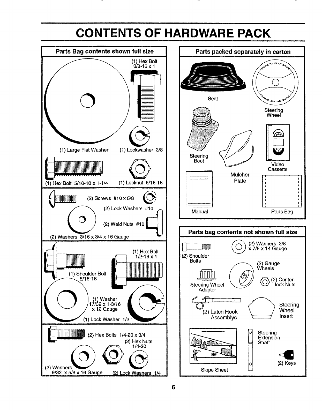
CONTENTS OF HARDWARE PACK
Parts Bag contents shown full size
(1) Hex Bolt
3/8-16 x 1
(1) Large Flat Washer (t) Lockwasher 3/8
@
(1) Hex Bolt 5/t6-18 x 1-1/4 (1) Locknut 5/16-18
(2) Lock Washers #_
(2) Weld Nuts #10
(2) Washers 3/16 x 3/4 x 16 Gauge
(1) Shoulder Bolt
5/16-18
(1) Hex Bolt
1/2-13 x t
Washer'
x 1-3/16
x 12 Gauge
(1) Lock Washer 1/2
lllllllllllltilllllllH(2)Hex Bolts1/4-20 X 3/4
(2) Hex Nuts
9/32 x 5/8 x 16 Gauge f2) Lock Washers,,,,,,,,,,1.,,./.,4,,........
Seat
Steering
Boot
Mulcher
Plate
Steering
Wheel
Video
Cassette
t
Manual Parts Bag
i i,ii ii ,ll i , i , ,
Parts bag contents not shown full size
(2) Shoulder
Bolts
Steering Wheel
Adapter
2) Washers 3/8x 7/8 x 14 Gauge
(2) Gauge
Wheels
E'_, (2) Center-
lock Nuts
(2) Latch Hook
Assemblys
Steering
Wheel
Insert
Slope Sheet
Steering
Extension
Shaft
(2) Keys
6
ASSEMBLY
Your new tractor has been assembled at the factory withexception of those parts left unassembled for shipping purposes°
To ensure safe and proper operation of your tractor all parts and hardware you assemble must be tightened securely,, Use
the correct tools as necessary to insure proper tightness.
TOOLS REQUIRED FOR ASSEMBLY
A socket wrench set will make assembly easier_ Standard
wrench sizes are listed.
(2) 7/16" wrenches Tire pressure gauge
(2) 1/2" wrenches Phillips screwdriver
(1) 9/16" wrench Utility knife
(1) 3/4" socket with drive ratchet
When right or left hand is mentioned inthis manual, it
means when you are in the operating position (seated
behind the steering wheel).
TO REMOVE TRACTOR FROM CARTON
UNPACK CARTON
• Remove all accessible loose parts and parts cartons
from carton (See page 2).
• Cut, from top to bottom, along lines on all four corners
of carton, and lay panels ftato
° Check for any additional loose parts or cartons and
BEFORE ROLLING TRACTOR OFF SKID
ATTACH STEERING WHEEL (See Fig. 1)
ASSEMBLE EXTENSION SHAFT AND BOOT
• Slide extension shaft onto lower steering shaft° Align
mounting holes in extension and lower shafts and
install 5/16 hex bolt and IocknuL Tighten securely.
IMPORTANT: TIGHTEN BOLT AND NUT SECURELY TO
18-22 FT_LBS TORQUE.
° Place tabs of steering boot over tab slots in dash and
push down to secure.
INSTALL STEERING WHEEL
• Position front wheels of the tractor so they are pointing
straight forward.
° Slide steering wheel adapter onto steering shaft exten-
sion,,
= Position steering wheel so cross bars are horizontal
(left to right) and slide inside boot and onto adapter.
° Assemble large flat washer, 3/8 lock washer, 3/8 hex
bolt and tighten securely°
. Snap steering wheel insert into center of steering
wheel°
° Remove protective materials from tractor hood and
grill°
IMPORTANT; CHECK FOR AND REMOVE ANY STAPLES
IN SKID THAT MAY PUNCTURE TIRES WHERETRACTOR
IS TO ROLL OFF SK1Do
TO ROLL TRACTOR OFF SKID (See Operation
section for location and function of controls)
° Press lift lever plunger and raise attachment lift lever to
its highest position.
- Release parking brake by depressing clutch/brake
pedal
= Place gearshift lever in neutral (N) position,,
= Roll tractor backwards off skid.
° Remove banding holding discharge guard up against
tractor.
WHEEL
ADAPTER
STEERING
BOOT
EXTENSION SHAFT
7
5116 HEX BOLT
5/16 LOCKNUT
LOWER
STEERING
SHAFT
/
I
!
I
\
I
FIG. 1
HOW TO SET UP YOUR TRACTOR
CONNECT BATTERY (See Figs. 2 and 3)
CAUTION: Do not short battery termi-
nals by allowing a wrench or any other
object to contact both terminals at the
same time. Before connecting battery,
remove metal bracelets, wristwatch
bands, rings, etc.
Positive terminal must be connected
first to prevent sparking from acciden-
tal grounding.
i ii IlL iii i iiii ii iii I
= Remove cardboard packing from seat pan and liftseat
pan to raised position,
• Open battery box door,
° Remove terminal protective caps and discard,
• If this battery is put into service after month and year
indicated on label (label located between terminals)
charge battery for minimum of one hour at 6-10 amps,.
- Firstconnect RED batterycable to positive(+) terminal
withhex bolt,flat washer, lockwasher and hex nut as
shown., Tighten securely°
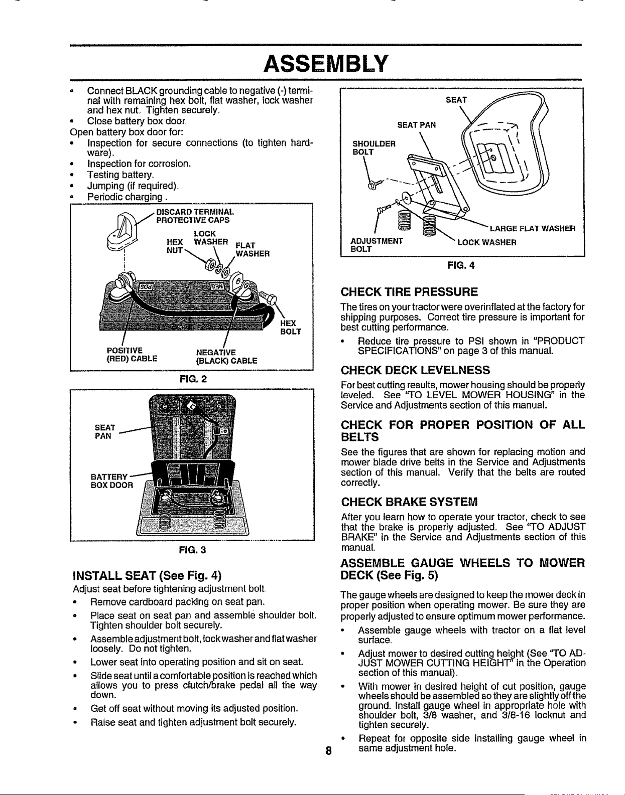
BLY
- Connect BLACK grounding cable to negative (-) termi-
nal with remaining hex bolt, flat washer, lock washer
and hex nut,. Tighten securely..
• Close battery box door,,
Open battery box door for:
• Inspection for secure connections (to tighten hard-
ware),,
• Inspection for corrosion.
• Testing battery°
• Jumping (if required).,
Periodic charging.
_ ISCARD TERMINAL
PROTECTIVE CAPS
LOCK
HEX WASHER FLAT
WASHER
t
SHOULDER
BOLT
SEAT PAN
SEAT
t
PosmvE NEGA_VE
(RED)CABLE (BLACK)CABLE
FIG. 2
BOLT
SEAT
PAN
BATTERY
BOXDOOR
FIG. 3
INSTALL SEAT (See Fig. 4)
Adjust seat before tightening adjustment boit_
- Remove cardboard packing on seat pan°
- Place seat on seat pan and assemble shoulder bolt.
Tighten shoulder bolt securely,,
• Assemble adjustment bolt, lockwasher and flat washer
loosely_ Do not tighten,,
• Lower seat into operating position and sit on seat.
• Slide seat until a comfortable position is reached which
allows you to press clutch/brake pedal all the way
down°
• Get off seat without moving its adjusted position.
= Raise seat and tighten adjustment bolt securely.
ADJUSTMENT
BOLT
LARGE FLAT WASHER
LOCK WASHER
FIG. 4
8
CHECK TIRE PRESSURE
The tires on your tractor were overinflated at the factory for
shipping purposes° Correct tire pressure is important for
best cutting performance.
° Reduce tire pressure to PSI shown in "PRODUCT
SPECIFICATIONS" on page 3 of this manual.
CHECK DECK LEVELNESS
For best cutting results, mower housing should be properly
leveled. See "TO LEVEL MOWER HOUSING" in the
Service and Adjustments section of this manual°
CHECK FOR PROPER POSITION OF ALL
BELTS
See the figures that are shown for replacing motion and
mower blade drive belts in the Service and Adjustments
section of this manual. Verify that the belts are routed
correctly.
CHECK BRAKE SYSTEM
After you learn how to operate your tractor, check to see
that the brake is properly adjusted. See "TO ADJUST
BRAKE" in the Service and Adjustments section of this
manual.
ASSEMBLE GAUGE WHEELS TO MOWER
DECK (See Fig. 5)
The gauge wheeJs are designed to keep the mower'deck in
proper position when operating mower, Be sure they are
properly adjusted to ensure optimum mower performance.
° Assemble gauge wheels with tractor on a flat level
surface,
• Adjust mower to desired cutting height (See '3"0 AD-
JUST MOWER CUTTING HEIGHT' in the Operation
section of this manual).
° With mower in desired height of cut position, gauge
wheels should be assembled so they are slightly offthe
ground. Install gauge wheel in appropriate hole with
shoulder bolt, 3/8 washer, and 3/8-16 locknut and
tighten securely.
• Repeat for opposite side installing gauge wheel in
same adjustment holeo
i ,
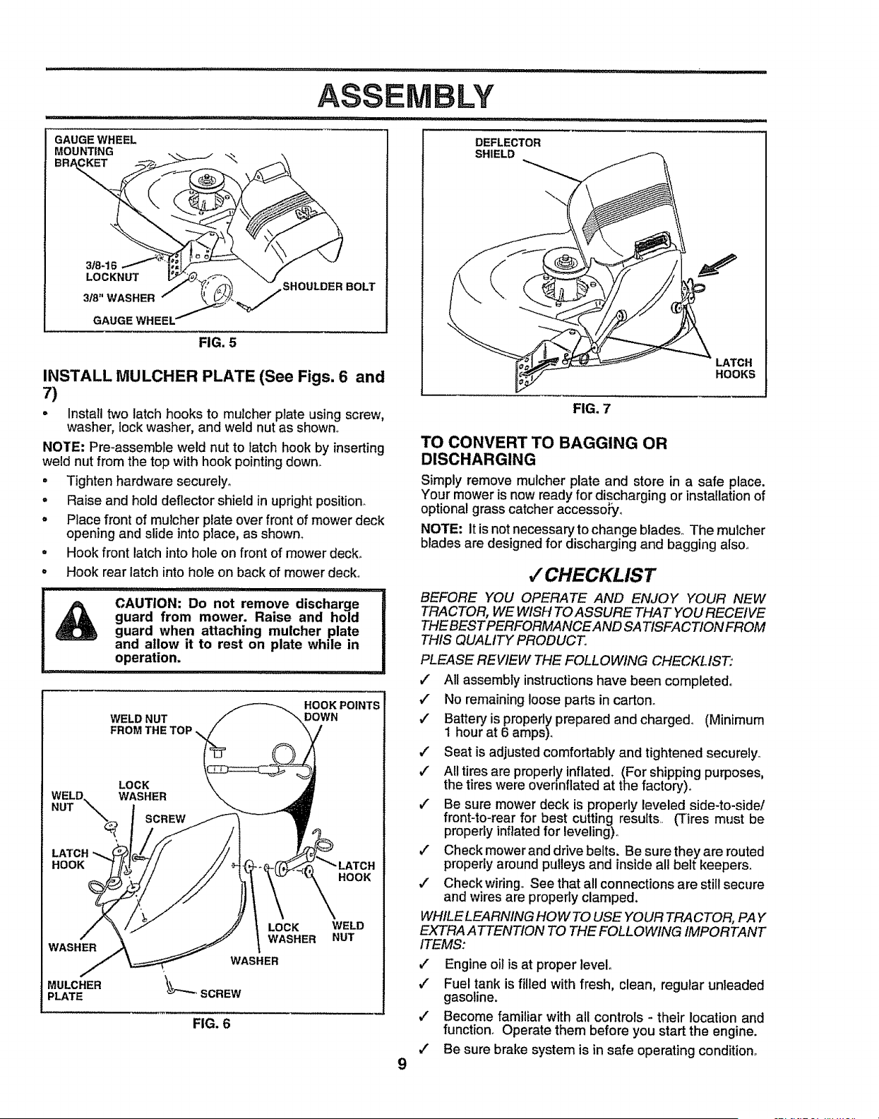
GAUGE WHEEL
MOUNTING
ASSEMBLY
IIIq"lH'_Hqll "_ql_l I' I "11'1 "1 '_ L
3!8-16
LOCKNUT
318" WASHER
GAUGE WHEEL'
FIG. 5
SHOULDER BOLT
INSTALL MULCHER PLATE (See Figs. 6 and
7)
- Install two latch hooks to mulcher plate using screw,
washer, lock washer, and weld nut as shown.
NOTE" Pre-assemble weld nut to latch hook by inserting
weld nut from the top with hook pointing down..
• Tighten hardware securely_
. Raise and hold deflector shield in upright position.
° Place front of mulcher plate over front of mower deck
opening and slide into place, as shown°
= Hook front latch into hole on front of mower deck.
= Hook rear latch into hole on back of mower deck°
CAUTION." Do not remove discharge
guard from mower. Raise and hold |
guard when attaching mulcher plate II
and allow it to rest on plate while in II
operation. ...................................
WELD NUT
FROM THE TOP
HOOK POINTS
DOWN
LOCK
LATCH
HOOK
HOOK
WASHER
MULCHER
PLATE
LOCK
WASHER
WASHER
WELD
NUT
FIG. 6
DEFLECTOR
SHIELD
9
FIG. 7
TO CONVERT TO BAGGING OR
DISCHARGING
LATCH
HOOKS
PLEASE REVIEW THE FOLLOWING CHECKLIST:
,I Al! assembly instructions have been completed°
•." No remaining loose parts in carton.
,/ Battery is properly prepared and charged° (Minimum
1 hour at 6 amps).
,/ Seat is adjusted comfortably and tightened securely.
,/ All tires are properly inflated. (For shipping purposes,
the tires were ovennflated at the factory).
,/ Be sure mower deck is properly leveled side-to-side/
front-to-rear for best cutting results. (Tires must be
properly inflated for leveling)°
,/ Check mower and drive belts. Be sure they are routed
properly around pulleysand inside all belt keepers.
,/ Check wiring° See that all connections are still secure
and wires are properly clamped.
WHILE LEARNING HOW TO USE YOUR TRACTOR, PAY
EXTRA ATTENTION TO THE FOLLOWING IMPORTANT
ITEMS:
BEFORE YOU OPERATE AND ENJOY YOUR NEW
TRACTOR, WE WISH TO ASSURE THAT YOU RECEIVE
THE BESTPERFORMAIVCE AND SATISFACTION FROM
THIS QUALITY PRODUCT°
v" Engine oil is at proper level°
,./ Fuel tank is filled with fresh, clean, regular unleaded
gasoline.
,/ Become familiar with all controls - their location and
function. Operate them before you start the engine.
,/ Be sure brake system is in safe operating condition.
v" CHECKLIST
Simply remove mulcher plate and store in a safe place.
Your mower is now ready for discharging or installation of
optional grass catcher accessory_
NOTE: It is not necessary to change blades.. The mulcher
blades are designed for discharging and bagging also,.
OPERATION
............................... ......................... iii i
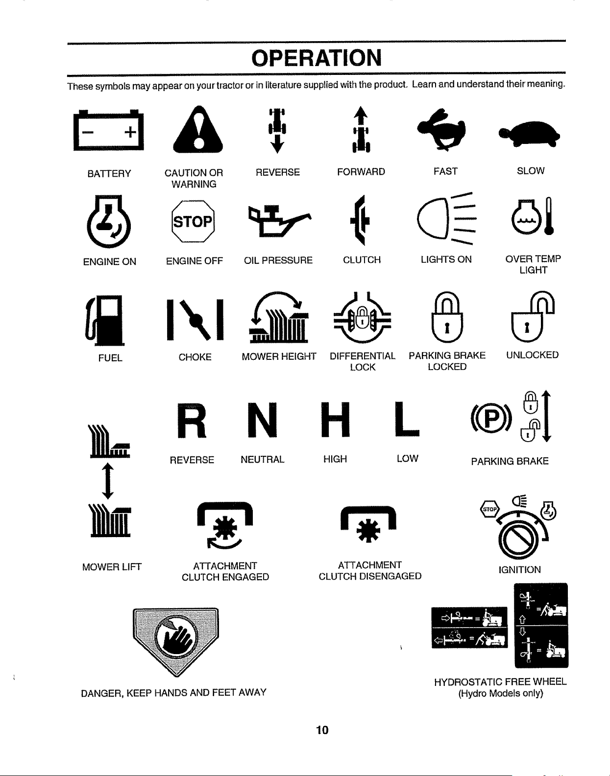
These symbols may appear on your' tractoror inliterature supplied with the product, Learn and understand their meaning_
t
A =.
BATTERY CAUTION OR REVERSE
WARNING
FORWARD FAST SLOW
CLUTCH LIGHTS ON
ENGINE ON ENGINE OFF OIL PRESSURE OVER TEMP
LIGHT
I",.I-
FUEL CHOKE MOWER HEIGHT DIFFERENTIAL PARKING BRAKE
LOCK LOCKED
UNLOCKED
N H L
REVERSE NEUTRAL HIGH LOW
PARKING BRAKE
MOWER LIFT
ATTACHMENT
CLUTCH ENGAGED
ATTACHMENT
CLUTCH DISENGAGED
IGNITION
DANGER, KEEP HANDS AND FEET AWAY
HYDROSTATIC FREE WHEEL
(Hydro Models only)
10
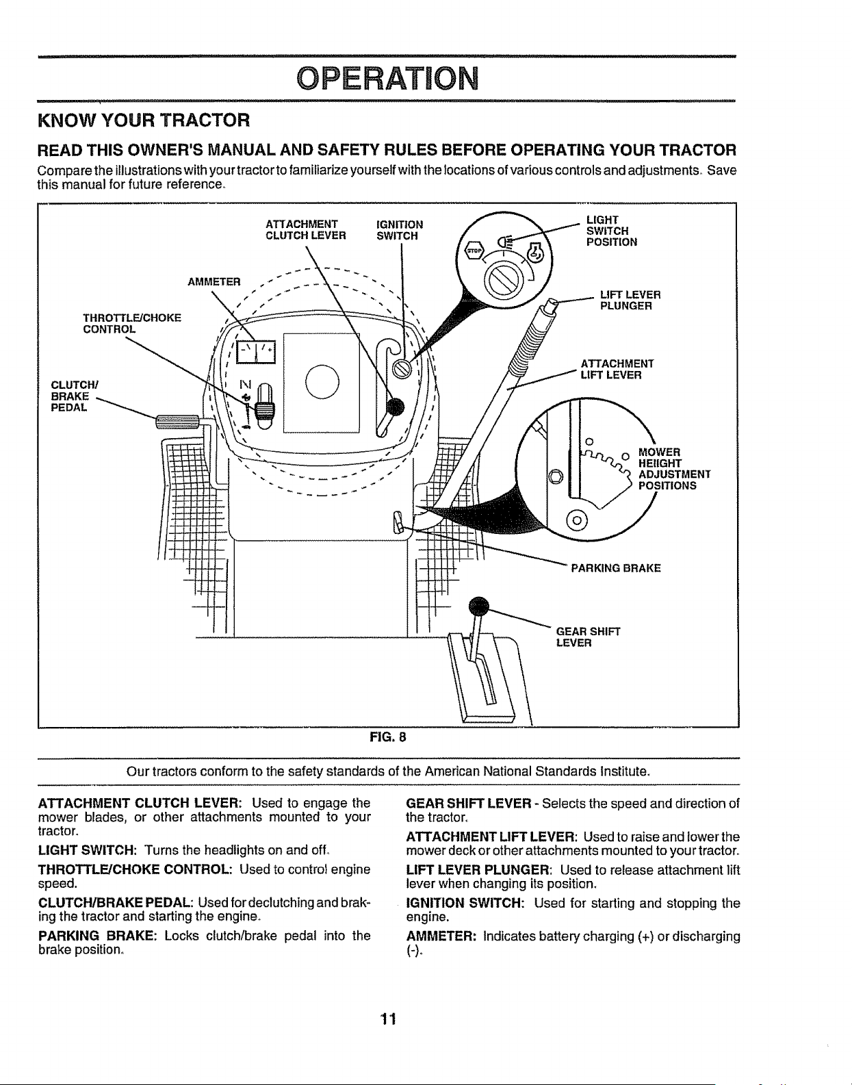
OPERATION
KNOW YOUR TRACTOR
READ THIS OWNER'S MANUAL AND SAFETY RULES BEFORE OPERATING YOUR TRACTOR
Compare the illustrationswithyour tractorto familiarize yourselfwiththe locations ofvariouscontrolsand adjustments_Save
this manual for future reference.
THROTTLFJCHOKE
CONTROL
ATTACHMENT IGNITION LIGHT
SWITCH
CLUTCH LEVER SWITCH POSITION
AMMETER . " "
_-\\< ,. .. ., LIFT LEVER
,' t " PLUNGER
CLUTCH/
BRAKE
PEDAL
ATTACHMENT
UFTLEVER
O
\
MOWER
HEIIGHT
ADJUSTMENT
POSITIONS
PARKING BRAKE
GEARSHIFT
LEVER
FIG. 8
Our tractors conform to the safety standards of the American National Standards Institute,
ATTACHMENT CLUTCH LEVER: Used to engage the
mower blades, or other attachments mounted to your
tractor°
LIGHT SWITCH: Turns the headlights on and off,+
THROTTLE/CHOKE CONTROL: Used to control engine
speed.
CLUTCHtBRAKE PEDAL: Used for declutching and brak+
ing the tractor and starting the engine,,
PARKING BRAKE: Locks clutch/brake pedal into the
brake position°
GEAR SHIFT LEVER - Selects the speed and direction of
the tractor+
ATTACHMENT UFT LEVER: Used to raise and lowerthe
mower deck or other attachments mounted to you r tractor.,
LIFT LEVER PLUNGER: Used to release attachment lift
lever when changing its position,
IGNITION SWITCH: Used for starting and stepping the
engine.
AMMETER: Indicates battery charging (+) or discharging
(-)o
1'1
The operation of any tractor can result in foreign objects thrown into the eyes, which can
result in severe eye damage. Always wear safety glasses or eye shields while operating your
tractor or performing any adjustments or repairs. We recommend a wide vision safety mask
over the spectacles or standard safety glasses.
HOW TO USE YOUR TRACTOR
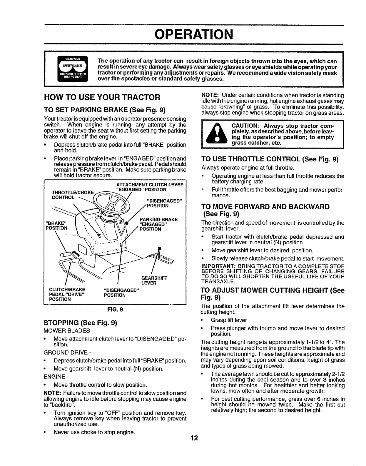
TO SET PARKING BRAKE (See Fig. 9)
Your tractorisequipped with an operator presence sensing
switch° When engine is running, any attempt by the
operator'to leave the seat without first settingthe parking
brake will shut off the engine,.
• Depress clutch/brake pedal intofull "BRAKE" position
and hold_
- Place parking brake lever in' ENGAGED"position and
release pressure from clutch/brake pedal, Pedatshould
remain in"BRAKE" position° Make sure parking brake
will hold tractor secure_
THROTTLE/CHOKE
CONTROL
ATTACHMENT CLUTCH LEVER
"ENGAGED" POSITION
"BRAKE"
POSITION
PARKING BRAKE
"ENGAGED"
CLUTCH/BRAKE "DISENGAGED"
PEDAL "DRIVE" POSITION
POSITION
FIG. 9
GEARSHIFT
LEVER
STOPPING (See Fig. 9)
MOWER BLADES -
• Move attachment clutch lever to "DISENGAGED" po-
sition_
GROUND DRIVE-
• Depress clutch/brake pedal intofull "BRAKE" position.
• Move gearshift lever to neutral (N) position_
ENGINE -
° Move throttle control to slow position.
NOTE: Failure to move throttle control to slow position and
allowing engine to idle before stopping may cause engine
to "backfire".
° Turn ignition key to "OFF" position and remove key.
Always remove key when leaving tractor to prevent
unauthorized use.
• Never use choke to stop engine.
NOTE: Under certain conditions when tractor is standing
idlewith the engine running, hot engine exhaust gases may
cause "browning" of grass, To eliminate this possibility,
always stop engine when stopping tractor on grass areas.
l& .................................!
CAUTION: Always stop tractor com-
pletely,as described above, before leav-
ing the operator's position; to empty
grass catcher, etc.
t ................................
TO USE THRO3-rLE CONTROL (See Fig. 9)
Always operate engine at full throttle.
• Operating engine at less than full throttle reduces the
battery charging rate.
• Full throttle offers the best bagging and mower perfor-
mance_
TO MOVE FORWARD AND BACKWARD
(See Fig. 9)
The direction and speed of movement is controlledby the
gearshift lever_
• Start tractor' with clutch/brake pedal depressed and
gearshift lever in neutra_ (N) position,.
° Move gearshift lever to desired position..
• Slowly release clutch/brake pedal to start movement°
IMPORTANT; BRING TRACTOR TO A COMPLETE STOP
BEFORE SHIFTING OR CHANGING GEARS. FAILURE
TO DO SO WILL SHORTEN THE USEFUL LIFE OF YOUR
TRANSAXLE,.
TO ADJUST MOWER CUTTING HEIGHT (See
Fig. 9)
The positionof the attachment lift lever determines the
cutting height.
• Grasp lift lever.
• Press plunger with thumb and move lever to desired
position..
The cutting height range is approximately 1-1/2to 4". The
heights are measured from the ground to the blade tip with
the engine notrunning_These heights are approximate and
may vary depending upon soil conditions,height of grass
and types of grass being mowed.
• The average lawn should be cut to approximately2-1/2
inches during the cool season and to over 3 inches
during hot months. For healthier and better looking
lawns, mow often and after' moderate growth_
° For best cutting performance, grass over 6 inches in
height should be mowed twice. Make the first cut
relativelyhigh; the second to desired heighL
12
OPEBATn
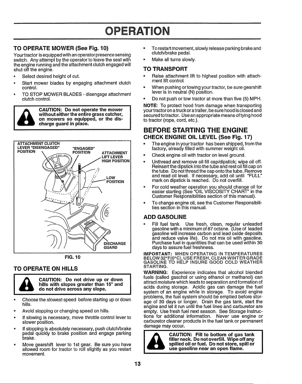
TO OPERATE MOWER (See Fig. 10)
Your tractor is equipped with an operator presence sensing
switch,, Any attempt by the operator to leave the seat with
the engine running and the attachment clutch engaged will
shut off the engine°
o Select desired height of cut.
° Start mower blades by engaging attachment clutch
control,,
• TO STOP MOWER BLADES - disengage attachment
clutch control
CAUTION: Do not operate the mower
without either the entire grass catcher,
on mowers so equipped, or the dis-
charge guard in place.
ATTACHMENT CLUTCH
LEVER "DISENGAGED"
POSITION
"ENGAGED"
"\\_._ _ POSITION ATTACHMENT
"._"_ i - LIFT LEVER
{/_'_;_,/ i_ HIGHPOslTION
)_'_ _ :_ZCHARGE
/ / _ GUARD
FIG. 10
TO OPERATE ON HILLS
,i,i1,1,,,,,,,,,,,,,,,_,,_,_,_,,,,,,,,,,,_,,_,
I _ CAUTION: Do not drive up or down
hills with slopes greater than 15° and
do not drive across any slope.
°
o
w
o
Choose the slowest speed before starling up ordown
hills,,
Avoid stopping or changing speed on hills.
If slowing is necessary, move throttle control lever to
slower position.
If stopping is absolutely necessary, push clutch/brake
pedal quickly to brake position and engage parking
brake.,
Move gearshift lever to 1st gear. Be sure you have
allowed room for tractor to roll slightly as you restart
movement.
• To restart movement, slowly release parking brake and
clutch/brake pedal,.
• Make all turns slowly_
TO TRANSPORT
° Raise attachment lift to highest position with attach-
ment tift control,,
° When pushing or towing your tractor, be sure gearshift
lever is in neutral (N) position°
= Do not push or tow tractor at more than five (5) MPH.
NOTE: To protect hood from damage when transporting
your tractor on a truck or atrailer, be sure hood is closed and
secured to tractor. Use an appropriate means of tying hood
to tractor (rope, cord, etc,,),,
BEFORE STARTING THE ENGINE
CHECK ENGINE OIL LEVEL (See Fig. 17)
= The engine inyour tractor has been shipped, from the
factory, already filled with summer weight oil
= Check engine oil with tractor on level ground.
o Unthread and remove oil fill cap/dipstick; wipe oil off,,
Reinsert the dipstick into the tube and rest oil fill cap on
the tube. Do not thread the cap onto the tube. Remove
and read oil level. If necessary, add oil until "FULL"
mark on dipstick is reached. Do not overfill°
o For cold weather operation you should change oil for
easier starting (See OIL VISCOSITY CHART' in the
Customer Responsibilities section of this manual).
° To change engine oil, see the Customer Responsibili-
ties section in this manual°
ADD GASOLINE
o Fill fuel tank_ Use fresh, clean, regular unleaded
gasoline with a minimum of 87 octane. (Use of leaded
gasoline will increase carbon and lead oxide deposits
and reduce valve life),, Do not mix oil with gasoline.
Purchase fuel in quantities that can be used within 30
days to assure fuel freshness°
IMPORTANT: WHEN OPERATING IN TEMPERATURES
O O
BELOW32 F(0 C), USE FRESH, CLEAN WINTER GRADE
GASOLINE TO HELP INSURE GOOD COLD WEATHER
STARTING°
WARNING: Experience indicates that alcohol blended
fuels (called gasohol or using ethanol or methanol) can
attract moisture whichleads to separation and formation of
acids during storage. Acidic gas can damage the fuel
system of an engine while in storage° To avoid engine
problems,the fuel system should be emptied before stoF
age of 30 days or longer. Drain the gas tank, start the
engine and let it run until the fuef lines and carburetor are
empty. Use fresh fuel next season. See Storage Instruc-
tions for additional information,. Never use engine or
carburetorcleaner products in the fuel tank or permanent
damage may occur.
iiiiii i II II iiii I ii i i ii I I ii iiiii iiiiii iiiiiiiuiiiiii iiiii
CAUTION: Fill to bottom of gas tank
filler neck. Do not overfilL Wipe offany
spilled oil or fuel. Do not store, spill or
use gasoline near an open flame.
13
OPERATION
IIIIIIIIW Illllllllllllllll I Ill II ......................
TO START ENGINE (See Fig. 9) •
When starting the engine for the first time or if the engine
has run out of fuel, it will take extra cranking time to move
fuel from the tank to the engine. °
I
Sit on seat in operating position, depress clutch/brake
pedal and set parking brake°
= Place gear shift lever' in neutral (N) position°
° Move attachment clutch to "DISENGAGED" position.
° Move throttle control to choke position.
Note: Before starting, read the warm and cold starting
procedures below.
° insert keyinto ignition and turn key clockwise to"START"
position and release key as soon as engine starts. Do
not run starter continuously for more than fifteen sec-
onds per minute° If the engine does not start after
several attempts, move throttle control to fast position,
wait a few minutes and try again. If engine still does not
start, move the throttle control back to the choke
position and retry.
WARM WEATHER STARTING (50° F and above)
° When engine starts, movethe throttle control tothe fast
position_
• The attachments and grounddrive can now be used. tf
the engine does notaccept the load, restartthe engine
and allow itto warm up for one minute usingthe choke
as described above.
COLD WEATHER STARTING ( 50 ° F and below)
= When engine starts, allow engine to run with the throttle
control in the choke position until the engine runs
roughly, then move throttle control to fast position. This
may require an engine warm-up period from several
seconds to several minutes, depending on the tem-
perature.
• The attachments can also be used during the engine
warm-up period.
NOTE: If at a high altitude (above 3000 feet) or' in cold
temperatures (below 32 F) the carburetor fuel mixture may
needto beadjusted for best engine performance. See "TO
ADJUST CARBURETOR" in the Service and Adjustments
section of this manual.
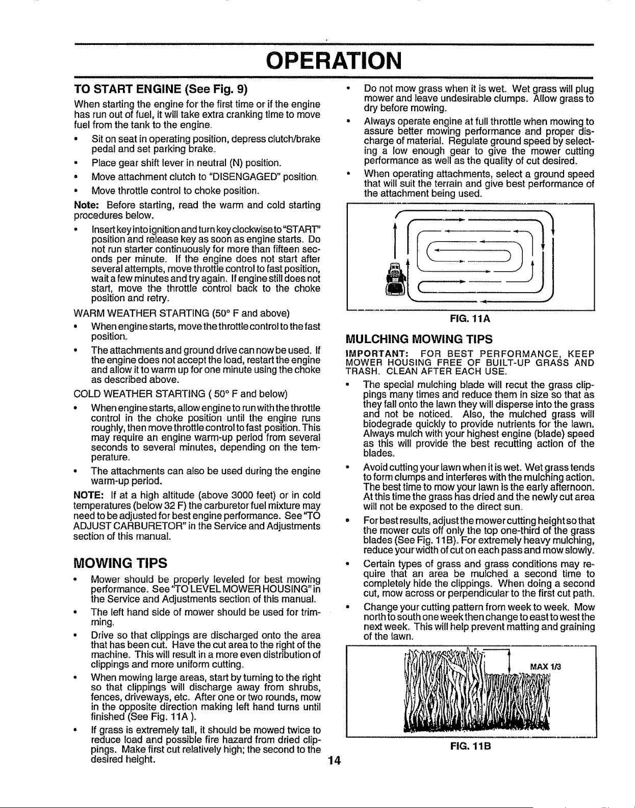
MOWING TIPS
° Mower should be properly leveled for best mowing
performance. See'q'O LEVEL MOWER HOUSING" in
the Service and Adjustments section of this manual°
= The left hand side of mower should be used for trim-
ming.
• Drive so that clippings are discharged onto the area
that has been cut. Have the cut area to the right of the
machine. This will result in a more even distribution of
clippings and more uniform cutting°
° When mowing large areas, start by turning to the right
so that clippings will discharge away from shrubs,
fences, driveways, etc_ After one or two rounds, mow
in the opposite direction making left hand turns until
finished (See Fig. 11A ).
° tf grass is extremely tall, it should be mowed twice to
reduce load and possible fire hazard from dried clip-
pings. Make first cut relatively high; the second to the
desired height.
Do not mow grass when it is wet. Wet grass will plug
mower and leave undesirable clumps. AIlow grass to
dry before mowing_
Always operate engine at full throttle when mowing to
assure better mowing performance and proper dis-
charge of matedaL Regulate ground speed by select-
ing a low enough gear to give the mower cutting
performance as well as the quality of cut desired.
When operating attachments, select a ground speed
that will suit the terrain and give best performance of
the attachment being used°
J
FIG. 11A
MULCHING MOWING TIPS
IMPORTANT: FOR BEST PERFORMANCE, KEEP
MOWER HOUSING FREE OF BUILT-UP GRASS AND
TRASH, CLEAN AFTER EACH USE.
The special mulching blade will recut the grass clip-
pings many times and reduce them in size so that as
they fall onto the lawn they will disperse into the grass
and not be noticed, Also, the mulched grass will
biodegrade quickly to provide nutrients for the lawn.
Always mulch with your highest engine (blade) speed
as this will provide the best recutting action of the
blades.
° Avoid cutting your lawn when itis wet. Wet grass tends
to form clumps and interferes with the mulching action.
The best time to mow your lawn isthe early afternoon.
At thistime the grass has dried and the newly cut area
will not be exposed to the direct sun..
= For bestresults,adjust the mowercutting height sothat
the mower cuts off only the top one-third of the grass
blades (See Fig. t 1B)..For extremely heavy mulching,
reduceyourwidth ofcut on each pass and mow slowly°
• Certain types of grass and grass conditions may re-
quire that an area be mulched a second time to
completely hide the clippings.. When doing a second
cut, mow across or perpendicular to the first cut path.
• Change your cuttingpattern from week to week. Mow
northto south oneweek thenchange to east to west the
next week. This will help prevent matting and graining
of the lawn.
MAX 1/3
14
FIG. 11B

i i
CUSTOMER RESPONSmBULmTmES
.... i ,, _ _ILI'H _ ' i ,_ i" II '11' IIIIU........................ III I1'"' II III I ........:: ........ I
MAINTENANCE SCHEDULE .,f___/_°_ _"
AsYouCOMPL E .......
REGULARSERVICE _,_ _ _'_/_ _ _ _ _,_'_. SERVICE DATES
.....
Check Brake Operation 6/ 64#
Check Tire Pressure _ 6/
IT check forLo0se Fasteners 6#€,
R Sharpeni'Repiace Mower Blades 6#44
A
Lubrication Chart V # if
IC ..........................
!T Check Ba,ttery LeveltRecharge
i 0 Clean Battery and Terminals _ 6/
R check Transaxle Cooling
Adjust Blade Belt(s) Tension 6€4_
Adjust Motion Drive Belt(s) Tension 6€#s
....i ,,,,..,. ,,,.
Check Engine Oil Level _
Change Engine Oil ........................ _1.2_3
Clean Air Filter 6_2
E Ciean Air Screen ............ _#'2 ....................
G Inspect Muffler/Spark Arrester
Replace Oil Filter (if equipped) 6€€_.2
Rep!ace,,,Spark Plug ................................. 6/ , _ .........
Replace Air Filter Paper Cartddge 6#42
Replace Fuel Filter
1- Change more often when operating under a heavy load or tn high ambient temperatures
2 * Service more oflen when operating in dirty or duslycondHtons
3 - ff equipped with otffilter, change oil ever/50 hours
4 - Replace blades more often when mowing In sandy soil
5 - If equipped with adjustable system
6 -Not required if equipped with malntenanee4ree batten/.
7 - Tighten front axle pivot belt to 35 ft,-lbs, maximum.
Do not ovedighten,
GENERAL RECOMMENDATIONS
The warranty on this tractor does not cover itemsthat have
been subjected to operator abuse or negligence. To
receive full value from the warranty, operator must maintain
tractor as instructed in this manual.
Some adjustments will need to be made periodically to
properly maintain your tractor,.
All adjustments in the Service and Adjustments section of
this manual should be checked at least once each season,.
Once a year you should replace the spark plug, clean
or replace air filter, and check blades and belts for
wear, A new spark plug and clean air filter assure
proper air-fuel mixture and help your engine run better
and last longer.
BEFORE EACH USE
• Check engine oil level
° Check brake operation,
° Checktire pressure.
• Check for Goosefasteners.
LUBRICATION CHART
(_)SPINDLE ZERK_ _ SPINDLE ZERK (_)
(_) ATTACHMENT _
CLUTCH
PIVOT(S)
(_) FRONT WHEEl :"_=_'_
BEARING ZERK -_.._.
=7==
15
ENGINE®
GEARSHIFT (_
PIVOTS
J
(_) SAE 30 OR 10W30 MOTOR OIL
(_) GENERAL PURPOSE GREASE
(_) REFER TO CUSTOMER RESPONSIBILITIES "ENGINE" SECTION
IMPORTANT: DO NOT OIL OR GREASE THE PIVOT POINTS
WHICH HAVE SPECIAL NYLON BEARINGS, VISCOUS LUBRI-
CANTS WILL ATTRACT DUST AND DIRT THAT WILL SHORTEN
THE LIFE OF THE SELF-LUBRICATING BEARINGS. IF YOU
FEEL THEY MUST BE LUBRICATED, USE ONLY A DRY, POW-
DERED GRAPHITE TYPE LUBRICANT SPARINGLY_
CUSTOMER RESPONSIBILITIES
.............................................. iii ILIIIIIIIIEIIIIJlIII i i
TRACTOR
Always observe safety rules when performing any mainte-
nanceo
BRAKE OPERATION
if tractor requires more than six (6) feet stopping distance
at high speed in highest gear',then brake must be adjusted,
(See '3"0 ADJUST BRAKE" in the Service and Adjust-
ments section of this manual).
TIRES
• Maintain proper air pressure in all tires (See "PROD-
UCT SPECIFICATIONS" on page 3 of this manual).
• Keep tires free of gasoline, oil, or insect control chemi-
cals which can harm rubber'.
• Avoid stumps, stones, deep ruts, sharp objects and
other hazards that may cause tire damage.
NOTE: To seal tire punctures and prevent flat tires due to
slow leaks, tire sealant may be purchased from your' local
parts dealer. Tire sealant also prevents tire dry rot and
corrosion°
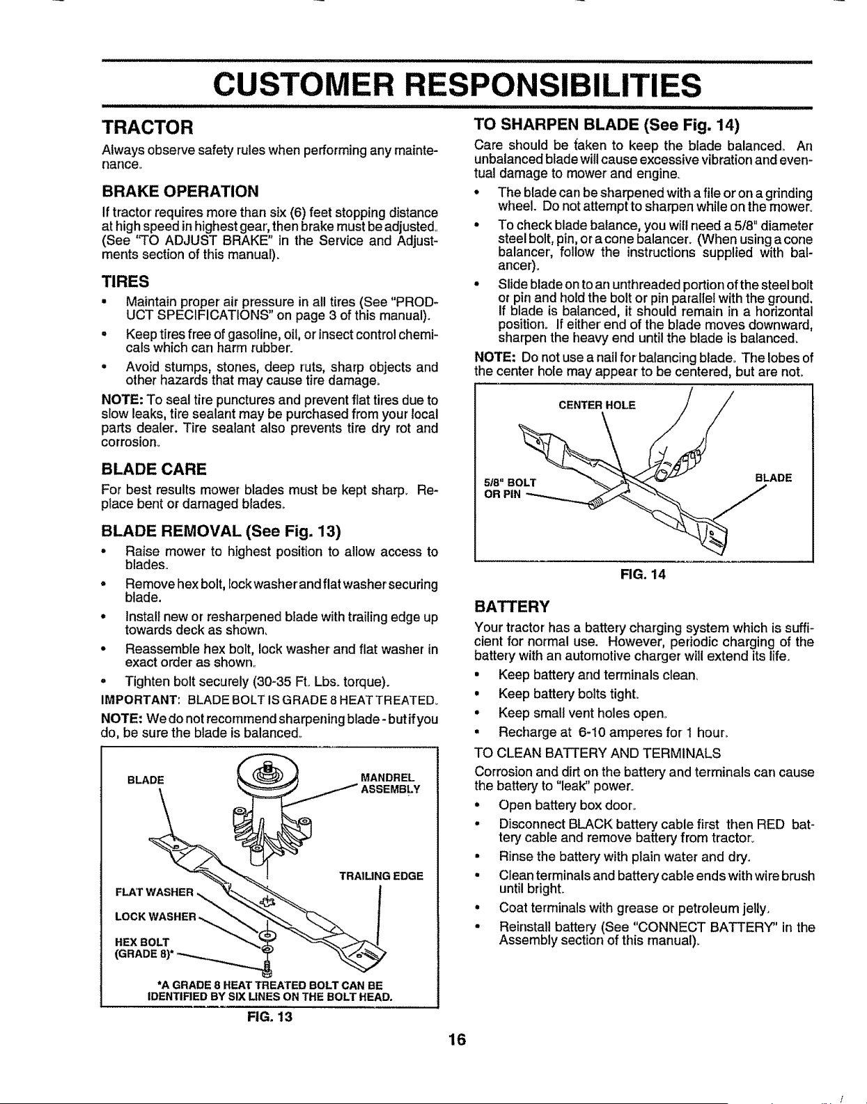
BLADE CARE
For best results mower blades must be kept sharp. Re-
place bent or damaged blades..
BLADE REMOVAL (See Fig. 13)
• Raise mower to highest position to allow access to
blades..
• Remove hex bolt, Iockwasher and flat washer securing
blade.
• installnew or resharpened blade with trailing edge up
towards deck as shown,
• Reassemble hex bolt, lock washer' and flat washer in
exact order as shown..
• Tighten bolt securely (30-35 Ft. Lbs. torque).
IMPORTANT: BLADE BOLT IS GRADE 8 HEATTREATED.
NOTE; We do not recommend sharpening blade- butifyou
do, be sure the blade is balanced_
BLADE MANDREL
ASSEMBLY
HEX BOLT
(GRADE8)*
TRAIUNG EDGE
*A GRADE 8 HEAT TREATED BOLTCAN BE
IDENTIRED BYSIX UNES ON THEBOLTHEAD.
TO SHARPEN BLADE (See Fig. 14)
Care should be {aken to keep the blade balanced_ An
unbalancedblade willcause excessive vibrationand even-
tual damage to mower and engine.
• The blade can be sharpened witha file oron a grinding
wheel. Do not attempt to sharpen while onthe mower.
• To check blade balance, you willneed a 5/8" diameter
steel bolt, pin,oracone balancer. (When using a cone
balancer, follow the instructions supplied with bal-
ancer)o
• Slide blade on to an unthreaded portion ofthe steel boFt
or pin and hold the bolt or pin parallel withthe ground.
if blade is balanced, it should remain in a horizontal
position. If either' end of the blade moves downward,
sharpen the heavy end until the blade is balanced.
NOTE: Do not use a nail for balancing blade. The lobes of
the center hole may appear to be centered, but are not.
CENTER HOLE
5/8" BOLl
OR PIN
BLADE
FIG. 14
BATTERY
Your tractor has a battery charging system which is suffi-
cient for normal use. However, periodic charging of the
battery with an automotive charger will extend its life.
• Keep battery and terminals clean,
• Keep battery bolts tight.
• Keep small vent holes open..
• Recharge at 6-10 amperes for 1 hour_
TO CLEAN BATTERY AND TERMINALS
Corrosion and dirt on the battery and terminals can cause
the battery to "leak" power.
• Open battery box door..
• Disconnect BLACK battery cable first then RED bat-
tery cable and remove battery from tractor°
• Rinse the battery with plain water and dry.
• Clean terminals and battery cable ends with wire brush
until bright.
• Coat terminals with grease or petroleum jelly.
• Reinstall battery (See "CONNECT BATTERY" in the
Assembly section of this manual).
FIG. 13
16
i ,ml, iLmm,ram I "1'1'1,I'1'ira,m,ll,ml,i,I "1 ml
CUSTOMER
V-BELTS
Check V-belts for deterioration and wear after 100 hours of
operation and replace if necessary. The belts are not
adjustable° Replace belts if they begin to slip from wear,
TRANSAXLE COOLING
Keep transaxle free from build-up of dirt and chaff which
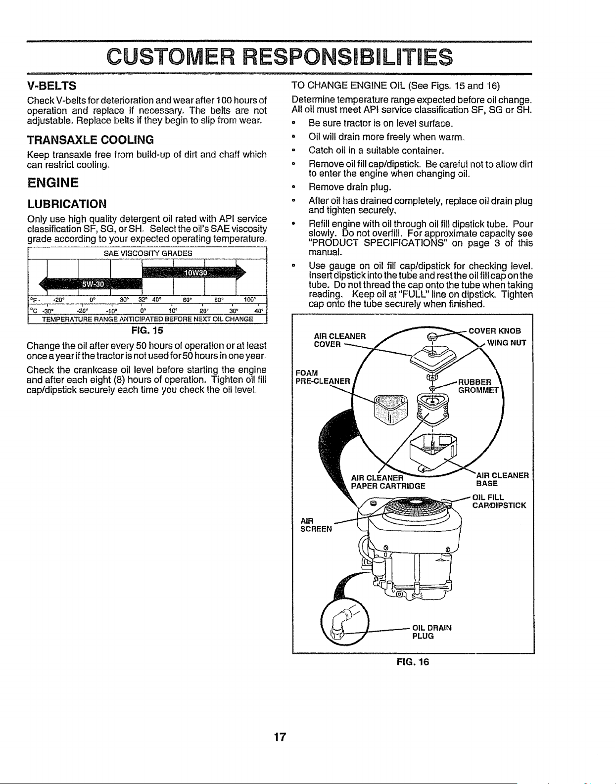
can restrict cooling.
ENGINE
LUBRICATION
Only use high quality detergent oil rated with API service
classification SF, SG, or SH Select the oil's SAE viscosity
grade according to your expected operating temperature.
SAE V(SCOSITY GRADES
i .........
"F" "20° 0° 30 _ 32" 40 _ 60 _ 80 _ 100"
°c - oo -t6= 6° 1'o, 3'oo .'0o
TEMPERATURE RANGE AI',Ft'IC1PATED BEFORE NEXT OIL CHANGE
FIG. 15
Change the oil after every 50 hours of operation or at least
once a year if the tractor is not used for 50 hours inone year°
Check the crankcase oil level before starting the engine
and after each eight (8) hours of operation_ Tighten oil fiU
cap!dipstick securely each time you check the oil level,
,,n,,_",_l,m,mmn, iml,,mi, _ Im
IBmLITHES
TO CHANGE ENGINE OIL (See Figs. 15 and 16)
Determinetemperature range expected before oilchanger
All oi! must meet API service classificationSF, SG or SH_
o Be sure tractor is on level sufface_
• Oil will drain more freely when warm
° Catch oil in a suitable container.
° Remove oilfill cap/dipstick. Be careful not to allow dirt
to enter the engine when changing oil,.
° Remove drain plug.
° After oil has drained completely, replace oil drain plug
and tighten securely.
• Refillengine withoil through oil fill dipstick tube. Pour
slowly. Do not overfill. For approximate capacity see
"PRODUCT SPECIFICATIONS" on page 3 of this
manual,.
= Use gauge on oil fill cap/dipstick for checking level
tnsert dipstick into the tube and rest the oil fill cap on the
tube. Do not thread the cap onto the tube when taking
reading. Keep oil at "FULL" line on dipstick,, Tighten
cap onto the tube securely when finished°
AIR CLEANER KNOB
COVE , WING NUT
FOAM
PRE-CLEANER
PAPER CARTRIDGE
AIR
SCREEN
PLUG
BASE
CAP/DIPSTICK
FIG. 16
17
,,,,,,, ,,,, ,,,,,,,,,,,,,,,,,,,,,,,,,,,,,,,,,,,,,,,,,,,,,,,,,,,,,,,,,,,,,,,,,, ,, ,, ,,,,
......................................... i,i i I I I Jlll II ILl IIIIIIIIIIIIIIIIII II II I I! LIIIIIII I I II I I , , i
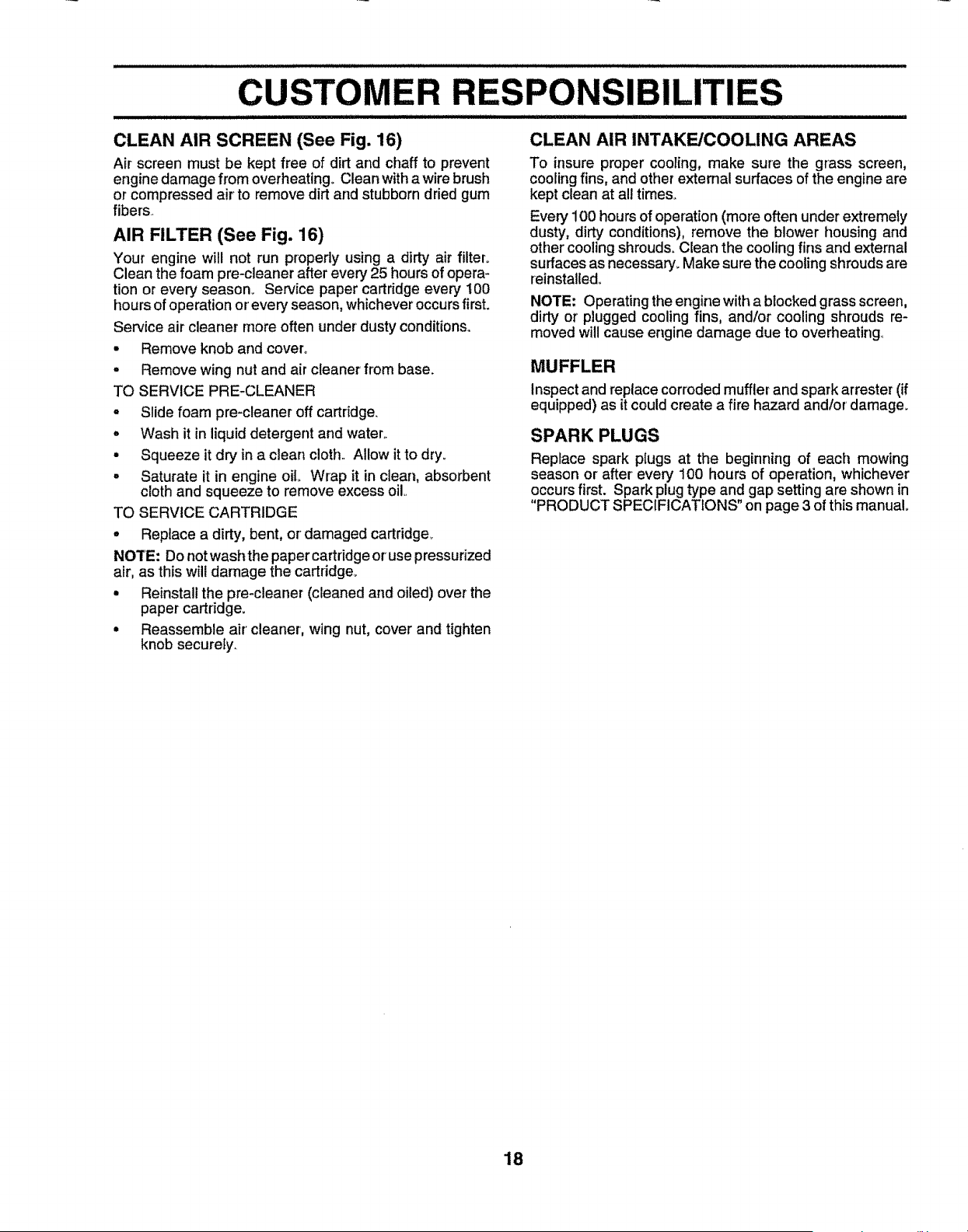
CLEAN AIR SCREEN (See Fig. 16) CLEAN AIR INTAKE/COOLING AREAS
Air screen must be kept free of dirt and chaff to prevent
engine damage from overheating° Clean with awire brush
or compressed air to remove dirt and stubborn dried gum
fibers
AIR FILTER (See Fig. 16)
Your engine will not run properly using a dirty air filter.
Clean the foam pre-cleaner after every 25 hours of opera-
tion or every season. Service paper cartridge every 100
hours of operation or'every season, whichever occurs first.
Service air cleaner more often under' dusty conditions.
• Remove knob and cover.
• Remove wing nut and air cleaner from base.
TO SERVICE PRE-CLEANER
° Slide foam pre-cleaneroff cartridge.
° Wash it in liquid detergent and water..
° Squeeze it dr,/in a clean cloth.. Allow it to dry.
• Saturate it in engine oil. Wrap it in clean, absorbent
cloth and squeeze to remove excess oil..
TO SERVICE CARTRIDGE
° Replace a dirty, bent, or damaged cartridge_
NOTE: Do notwash the paper cartridge or'use pressurized
air, as this will damage the cartridge.
° Reinstall the pre-cleaner (cleaned and oiled) over the
paper cartridge.
° Reassemble air' cleaner, wing nut, cover and tighten
knob securely.
To insure proper cooling, make sure the grass screen,
cooling fins, and other external surfaces of the engine are
kept clean at all times°
Every 100 hours of operation (more often under extremely
dusty, dirty conditions), remove the blower housing and
other cooling shrouds. Clean the cooling fins and external
surfaces as necessary. Make sure the cooling shrouds are
reinstalled_
NOTE: Operating the engine with a blocked grass screen,
dirty or plugged cooling fins, and/or cooling shrouds re-
moved will cause engine damage due to overheating°
MUFFLER
Inspectand replace corrodedmufflerand spark arrester (if
equipped) as it couldcreate a fire hazard and/or damage.
SPARK PLUGS
Replace spark plugs at the beginning of each mowing
season or after every 100 hours of operation, whichever
occurs first. Spark plug type and gap setting are shown in
"PRODUCT SPECIFICATIONS" on page 3 of this manual,
18

CUSTOMER RESPON ILITmES
ENGINE OIL FILTER (See Fig. 17)
Replace the engine oil filter every season or every other oil
change if the tractor is used more than 100 hours in one
year.
= Drain oil from engine crankcase (See "TO CHANGE
ENGINE OIL" in this section of this manual, through
step remove drain plug)_
= Remove oil filter and wipe off _ter adapter°
° Apply a thin coating of new engine oil to the rubber
gasket on replacement oil filter..
, Install replacement oil filter on filter adapter° Turn oil
filter clockwise until rubber gasket contacts the filter
adapter, then tighten filter an additional 1/2 turn..
= Fill crankcase with new oil (See 'qO CHANGE EN-
GINE OIL in this section of this manual). For approxi-
mate capacity see "PRODUCT SPECIFICATIONS" on
page 3 of this manual..
° Start the engine and check for oil leaks. Correct any
leaks before placing engine intofull operation_
OIL FILTER
,llr_lllH,,,l_lllll _ i, i
IN-LINE FUEL FILTER (See Fig. 18)
The fuel filter should be replaced once each season, if fuel
filter becomes clogged, obstructingfuel flow to carburetor,
replacement is required°
• With engine cool, remove _ter and plug fuel line
sections.
° Place new fuel filter in position in fuel line with arrow
pointingtowards carburetor,.
• Be sure there are no fuel line leaks and clamps are
properlypositioned.
= Immediatelywipe up any spilled gasolineo
CLAMP CLAMP
FUEL
FILTER
FIG. 18
CLEANING
- Clean engine, battery, seat, finish, etcoof all foreign
matter.
° Keep finished surfaces and wheels free ofall gasoline,
oil, etc_
° Protect painted surfaces with automotive type wax.
We do not recommend using a garden hose to clean your
tractor unless the electrical system, muffler, air filter and
carburetor are covered to keep water out. Water in engine
can result in a shortened engine life.
FIG. 17
19
SERVICE AND ADJUSTMENTS .........
CAUTION:
Q
e
e
BEFORE PERFORMING ANY SERVICE OR ADJUSTMENTS:
Depress clutch/brake pedal fully and set parking brake.
Place gearshift lever in neutral (N) position.
Place attachment clutch in "DISENGAGED" position.
Turn ignition key "OFF" and remove key.
Make sure the blades and all moving parts have completely stopped.
Disconnect spark plug wire from spark plug and place wire where it cannot come in contact with
plug.
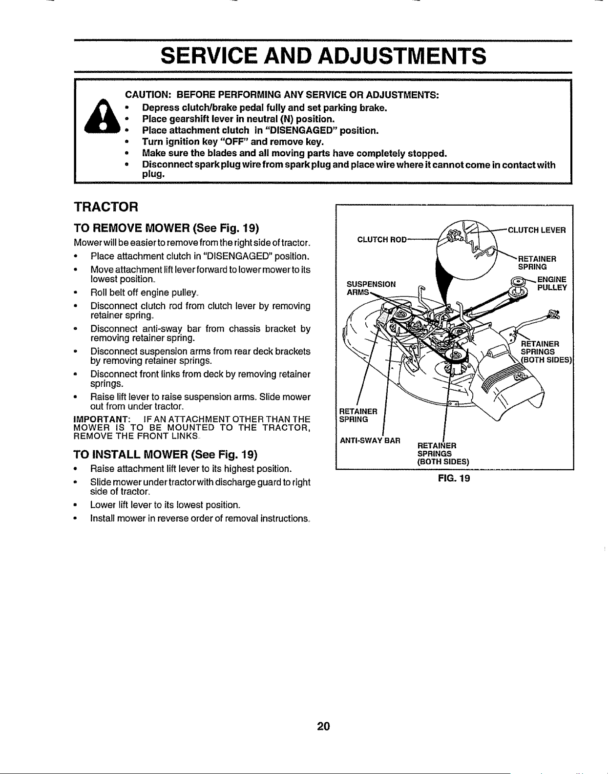
TRACTOR
TO REMOVE MOWER (See Fig. 19)
Mower will be easier toremove from the rightside of tractor.
• Place attachment clutch in "DISENGAGED" position.
° Move attachment lift lever for,_Jardto lower mower to its
lowest position.
= Roll belt off engine pulley°
• Disconnect clutch rod from clutch lever by removing
retainer spring°
= Disconnect anti-sway bar' from chassis bracket by
removing retainer spring.
, Disconnect suspension arms from rear deck brackets
by removing retainer springs.
- Disconnect front links from deck by removing retainer
springs.
° Raise lift lever to raise suspension arms. Slide mower
out from under tractor°
IMPORTANT: IF AN ATTACHMENT OTHER THAN THE
MOWER IS TO BE MOUNTED TO THE TRACTOR,
REMOVE THE FRONT LINKS..
TO INSTALL MOWER (See Fig. 19)
° Raise attachment lift lever to its highest position.
= Slide mower under'tractor with discharge guard to right
side of tractor.
• Lower lift lever to its lowest position.
• Install mower in reverse order of removal instructions,
CLUTCH
LEVER
SUSPENSION
SPRING
PULLEY
RETAINER
SPRINGS
BOTH SIDES
RETAINER
SPRING
ANTI-SWAY BAR
RETAI_ -ZR
SPRINGS
(BOTH SIDES)
FIG. 19
20
i _ illll i ,111 ,,i ill_l,JJJ ullll_l_l i _ ,,lllllll .......... n,n,,,,_llU iiii I _' '1
SERVmCE AND ADJUSTMENTS
llllllllmu ,i ,, t
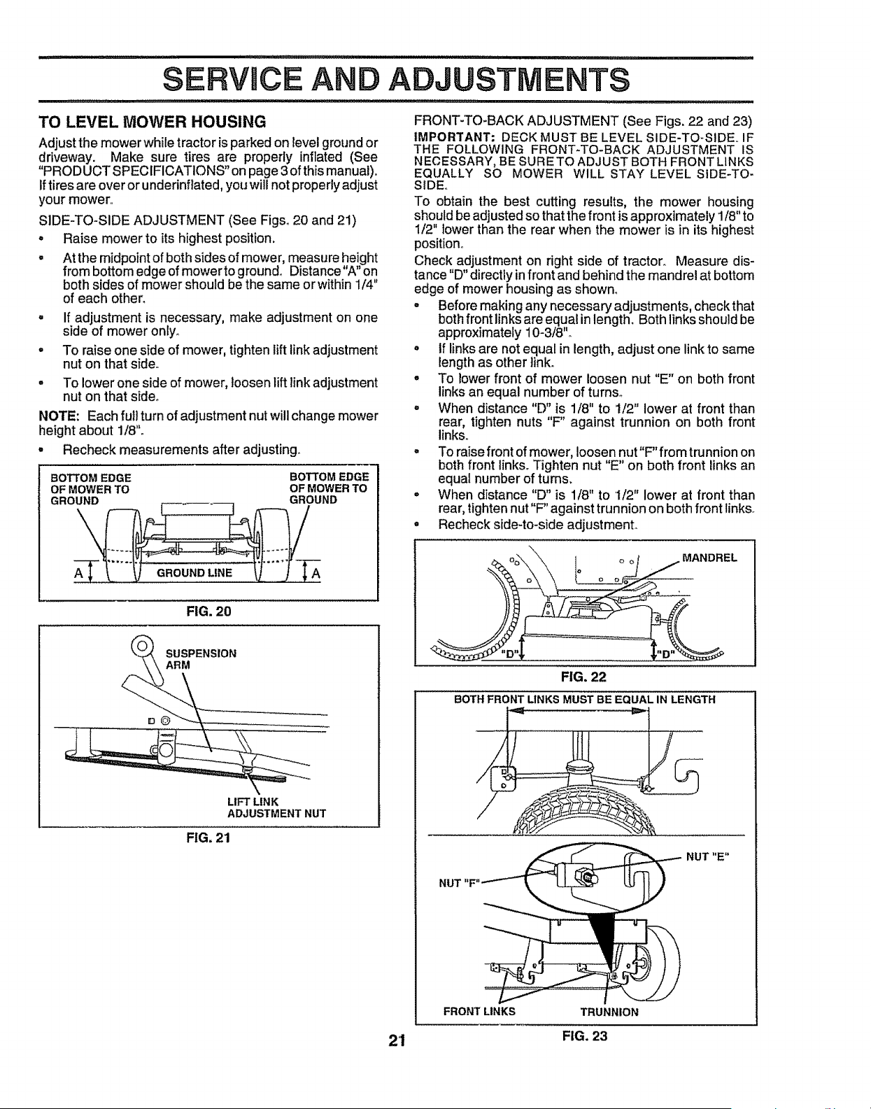
TO LEVEL MOWER HOUSING FRONT-TO-BACK ADJUSTMENT (See Figs. 22 and 23)
Adjust the mower while tractor is parked on level ground or
driveway. Make sure tires are properly inflated (See
"PROD UCT SPECIFICATIONS" on page 3 of this manual).
Iftires are over or underinflated, you will not properly adjust
your mower.
SIDE-TO-SIDE ADJUSTMENT (See Figs. 20 and 21)
° Raise mower to its highest position.
° At the midpoint of both sides of mower, measure height
from bottom edge of mower to ground_ Distance"A" on
both sides of mower should be the same or within 1/4"
of each other_
o
°
If adjustment is necessary, make adjustment on one
side of mower only_
To raise one side of mower, tighten lift link adjustment
nut on that side.
, To lower one side of mower, loosen lift link adjustment
nut on that side°
NOTE: Each fult turn of adjustment nut will change mower
height about 1/8".
, Recheck measurements after adjusting.
BOTTOM EDGE BOTTOM EDGE
OF MOWER TO OF MOWER TO
GROUND GROUND
IMPORTANT: DECK MUST BE LEVEL SIDE-TO-SIDE IF
THE FOLLOWING FRONT-TO-BACK ADJUSTMENT IS
NECESSARY, BE SURE TO ADJUST BOTH FRONT LINKS
EQUALLY SO MOWER WILL STAY LEVEL SIDE-TO-
SIDE.
To obtain the best cutting results, the mower housing
should be adjusted so that the front is approximately 1/8" to
1/2" lower than the rear when the mower is in its highest
position°
Check adjustment on right side of tractor.. Measure dis-
tance "D" directly infront and behind the mandrel at bottom
edge of mower housing as shown.
o Beforemaking any necessary adjustments, checkthat
both front linksare equal in length. Both linksshould be
approximately10-3/8"o
• If linksare notequal in length, adjust one linkto same
lengthas other tinko
° To lower front of mower loosen nut "E" on both front
links an equal number of turns°
° When distance "D" is 1/8" to 1/2" lower at front than
rear, tighten nuts "F' against trunnion on both front
links..
° To raise front of mower, loosen nut"F" from trunnion on
both front links. Tighten nut "E" on both front links an
equal number of turns.
• When distance "D" is 1/8" to 1/2" lower at front than
rear, tighten nut "F" against trunnion on both front links°
• Recheck side-to-side adjustment.
GROUND LINE A
FIG. 20
SUSPENSION
ARM
LIFT LINK
ADJUSTMENT NUT
FIG, 21
MANDREL
FIG. 22
BOTH FRONT LINKS MUST BE EQUAL IN LENGTH
NUT "E"
FRONTLINKS TRUNNION
2'1 FIG. 23
SERVICE AND ADJUSTMENTS
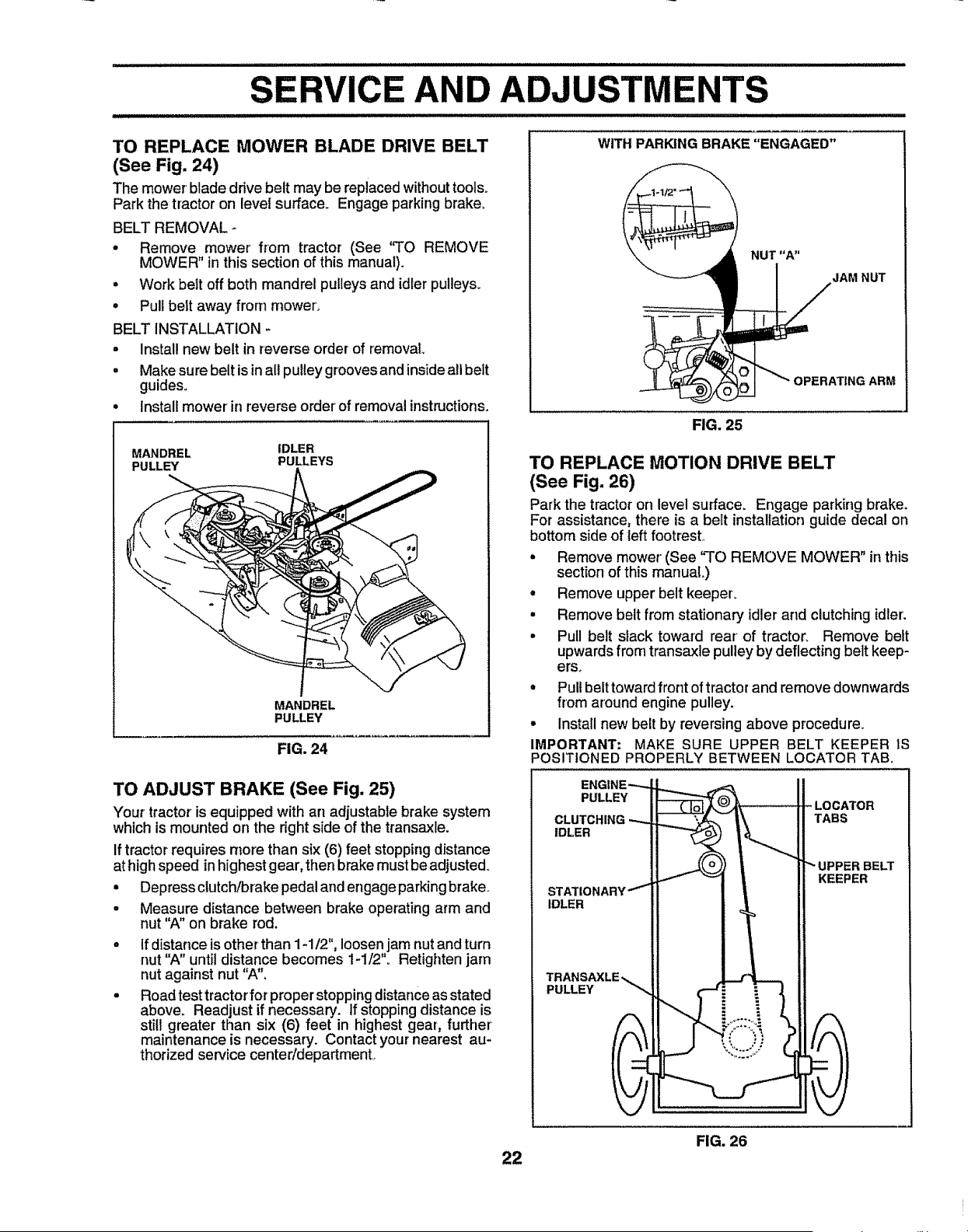
TO REPLACE MOWER BLADE DRIVE BELT
(See Fig. 24)
The mower blade drive belt may be replaced withouttools°
Park the tractor on level surface. Engage parking brake.
BELT REMOVAL -
• Remove mower from tractor (See 'q'O REMOVE
MOWER" in this section of this manual).
• Work belt off both mandrel pulleys and idler pulleys,.
• Pull belt away from mower,
BELT INSTALLATION -
= Install new belt in reverse order of removal
• Make sure belt is inall pulley grooves and inside all belt
guides.
• Install mower'in reverse orderof removal instructions.
MANDREL IDLER
PULLEY PULLEYS
MANDREL
PULLEY
FIG. 24
TO ADJUST BRAKE (See Fig. 25)
Your tractor is equipped with an adjustable brake system
which is mounted on the right side of the transaxle.
If tractor requires more than six (6) feet stopping distance
at highspeed inhighest gear, then brake must be adjusted.
• Depress clutch/brakepedal and engageparkingbrake..
• Measure distance between brake operating arm and
nut "A" on brake rod.
If distance is other than 1-1/2", loosen jam nut and turn
nut "A" until distance becomes 1-1/2". Retighten jam
nut against nut 'WL
Road test tractor for proper stopping distance as stated
above. Readjust if necessary. If stopping distance is
still greater than six (6) feet in highest gear, further
maintenance is necessary. Contact your nearest au-
thorized service centeddepartmenL
22
WITH PARKING BRAKE "ENGAGED"
FIG. 25
TO REPLACE MOTION DRIVE BELT
(See Fig. 26)
Park the tractor on level surface_ Engage parking brake.
For assistance, there is a belt installation guide decal on
bottom side of left footrest,.
• Remove mower' (See "TO REMOVE MOWER" in this
section of this manuaL)
• Remove upper belt keepeL
• Remove belt from stationary idler and clutching idler:
• Pull belt slack toward rear of tractor, Remove beft
upwardsfrom transaxle pulley by deflecting belt keep-
erso
° Pull belt towardfront of tractor and remove downwards
from around engine pulley.
° Install new belt by reversing above procedure.
IMPORTANT; MAKE SURE UPPER BELT KEEPER IS
POSITIONED PROPERLY BETWEEN LOCATOR TAB.
PULLEY
CLUTCHING
IDLER
IDLER
PULLEY
FIG. 26
SERVICE
i ,,,i,_,111,_11,11,,i........................ i HI,I, i, _H ,,l_lltll,_,_111,111,1,_111,1
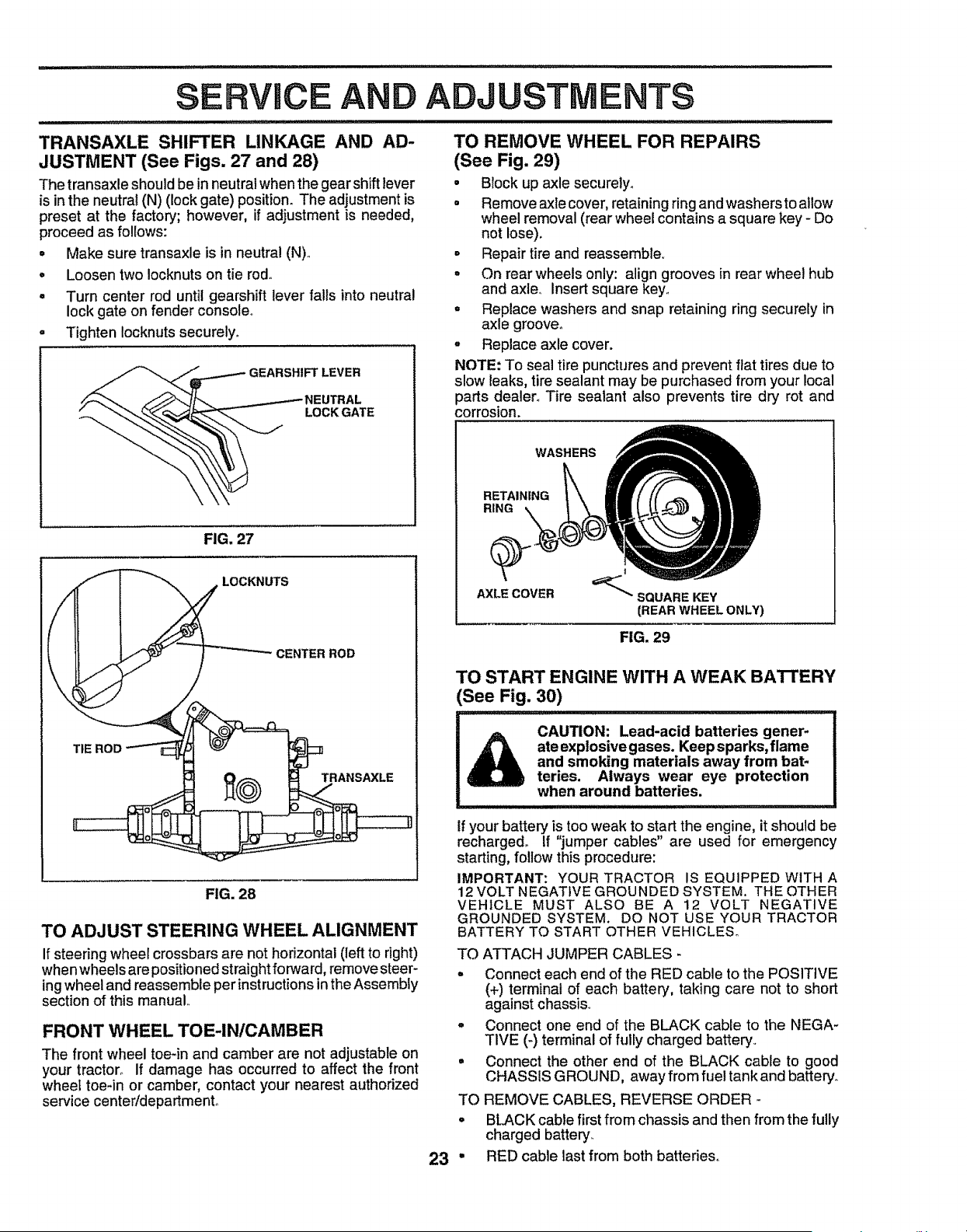
TRANSAXLE SHIFTER LINKAGE AND AD-
JUSTMENT (See Figs. 27 and 28)
The transaxle should be in neutral when the gearshift lever
is in the neutral (N) (lock gate) position. The adjustment is
preset at the factory; however, if adjustment is needed,
proceed as follows:
= Make sure transaxle is in neutral (N).
° Loosen two !ocknuts on tie rod.
° Turn center rod until gearshift lever falls into neutral
lock gate on fender console.
o Tighten Iocknutssecurely,
_IEUTRAL
LOCK GATE
FIG. 27
AND ADJUSTMENTS
TO REMOVE WHEEL FOR REPAIRS
(See Fig. 29)
• Block up axle securely°
• Remove axle cover, retainingringand washersto allow
wheel removal (rear wheel containsa square key - Do
not lose).
- Repair tire and reassemble,
• On rear wheels only: align grooves in rear wheel hub
and axleo Insert square key,
° Replace washers and snap retaining ring securely in
axle groove.
° Replace axle cover.
NOTE: To seal tire punctures and prevent flat tires due to
slow leaks, tire sealant may be purchased from your local
parts dealer° Tire sealant also prevents tire dry rot and
corrosion.
WASHERS
RETAINING
RING
AXLE COVER
'=_'_SQUARE KEY
(REAR WHEELONLY)
FIG. 29
FIG. 28
TO ADJUST STEERING WHEEL ALIGNMENT
If steering wheel crossbars are not horizontal (left to fight)
when wheels are positioned straightforward, remove steer-
ing wheel and reassemble per instructions inthe Assembly
section of this manual,
FRONT WHEEL TOE-IN/CAMBER
The front wheel toe-in and camber are not adjustable on
your tractor° If damage has occurred to affect the front
wheel toe-in or camber, contact your nearest authorized
service centeridepartmento
TO START ENGINE WITH A WEAK BA't-rERY
See Fig. 30)
CAUTION: Lead-acid batteries gener-
ate explosive gases. Keep sparks, flame
and smoking materials away from bat-
teries. Always wear eye protection
when around batteries.
o
TO
°
23"
If your battery is too weak to start the engine, it should be
recharged. If "jumper cables" are used for emergency
starting, follow this procedure:
IMPORTANT: YOUR TRACTOR IS EQUIPPED WITH A
12 VOLT NEGATIVE GROUNDED SYSTEM. THE OTHER
VEHICLE MUST ALSO BE A 12 VOLT NEGATIVE
GROUNDED SYSTEM. DO NOT USE YOUR TRACTOR
BATTERY TO START OTHER VEHICLES°
TO ATTACH JUMPER CABLES -
= Connect each end of the RED cable to the POSITIVE
(+) terminal of each battery, taking care not to short
against chassis
o Connect one end of the BLACK cable to the NEGA-
TIVE (-) terminal of fully charged battery,
Connect the other end of the BLACK cable to good
CHASSIS GROUND, away from fuel tank and battery°
REMOVE CABLES, REVERSE ORDER -
BLACK cable first from chassis and then from the fully
charged battery.
RED cable last from both batteries,

SE AND ADJUSTMENTS
POSITIVE TERMINAL
NEGATIVE TERMINAL
l lll iiii ii illllll llllqWl,lll i,=l ........................
TO REPLACE FUSE
Replace with 30 amp automotive-type plug-in fuse° The
fuse holder is located behind the dash.
TO REMOVE HOOD AND GRILL ASSEMBLY
(See Fig. 31)
• Raise hood._
° Unsnap headlight wire connector_
° Stand in front of tractor. Grasp hood at sides,tilt toward
engine and lift off of tractor.
° To replace, reverse above procedures.
CHARGED
POSITIVE NEGA_VE
TERMINAL TERMINAL
FIG. 30
TO REPLACE HEADLIGHT BULB
° Raise hood,
• Pul!bulb holder out of the hole in the backside of the
grill°
° Replace bulb in holder and push bulb holder securely
back into the hole in the backside of the gdlL
• Close hood.
INTERLOCKS AND RELAYS
Loose or damaged wiring may cause your tractor to run
poorly, stop running, or prevent it from starting.
• Check wiring. See electrical wiring diagram in the
Repair Parts section of this manual,
FIG. 31
24
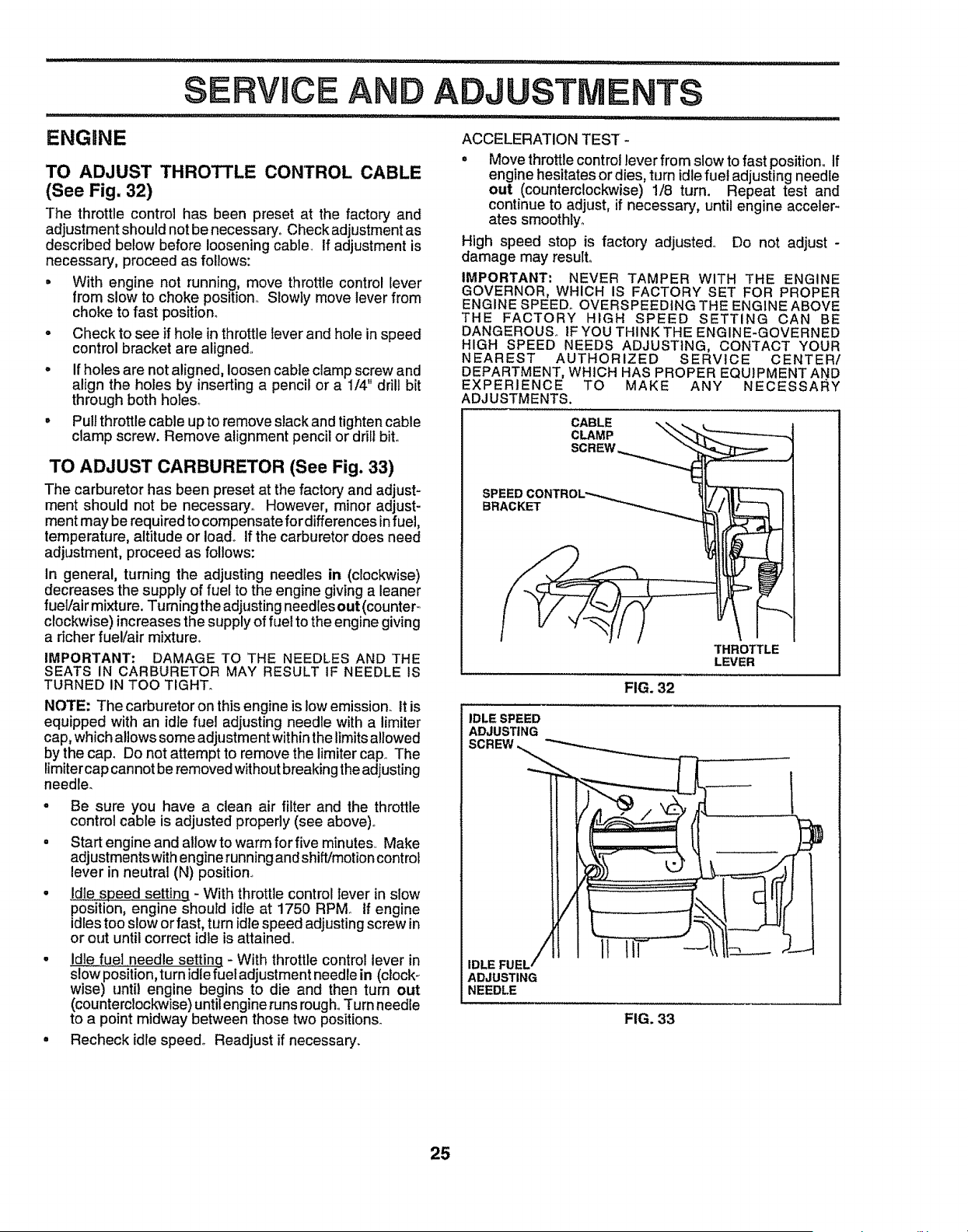
,,i,l,i ...... i,i ,,llllll ii , ,,i, i,,,,i,,
ENGI1NE
SERVICE AND ADJU
rl,r, i ,ll, ,,i ,i,i,,i,,i,,i'ill II "ll '
TO ADJUST THROTTLE CONTROL CABLE
(See Fig. 32)
The throttle control has been preset at the factory and
adjustmentshouldnotbe necessary,. Check adjustment as
described below before looseningcable_ If adjustment is
necessary', proceed as follows:
• With engine not running, move throttlecontrol tever
from slowto choke position..Slowty move lever from
choke to fast position_
- Check to see if hole in throttlelever and hote in speed
control bracket are aligned,,
- If holes are not aligned, loosencabie clamp screw and
align the holes by inserting a pencil or a 1/4" drill bit
through both holes_
. Pull throttlecable upto removeslack and tightencable
clamp screw. Remove alignment pencilor drilI bit.
TO ADJUST CARBURETOR (See Fig. 33)
The carburetor has been preset at the factory' and adjust-
ment should not be necessary° However, minor adjust-
ment may be required to compensate for differences in fuel,
temperature, altitude or Ioado if the carburetor does need
adjustment, proceed as follows:
In general, turning the adjusting needles in (clockwise)
decreases the supply of fuel to the engine giving a leaner
fuel!air mixture. Turning the adjusting needles out (counter-
clockwise) increases the supply of fuel to the engine giving
a dcher fue!/air mixture°
IMPORTANT: DAMAGE TO THE NEEDLES AND THE
SEATS IN CARBURETOR MAY RESULT IF NEEDLE IS
TURNED IN TOO TIGHT.
NOTE: The carburetor on thisengine is lowemission. It is
equipped with an idle fuel adjusting needle with a limiter
cap, which allows some adjustment within the limits allowed
by the cap. Do not attempt to remove the limiter cap° The
limiter cap cannot be removed without breaking the adjusting
needler
o Be sure you have a clean air filter and the throttle
control cable is adjusted properly (see above)°
• Start engine and allow to warm for five minutes.. Make
adjustmentswith engine running and shift/motion control
lever in neutral (N) position..
• !die speed setting - With throttle control lever in slow
position, engine shoutd idle at 1750 RPMo If engine
idlestoo slow or fast, turn idle speed adjusting screw in
or out until correct idle is attained..
• idle fuel needle setting - With throttle control lever in
slow position, turn idle fuel adjustment needle in (clock-
wise) until engine begins to die and then turn out
(counterclockwise) until engine runs rough,.Turn needle
to a point midway between those two positions.
• Recheck idle speed° Readjust if necessary_
ACCELERATION TEST
o Move throttle control lever from slow to fast position,, If
engine hesitates or dies, turn idle fuel adjusting needle
out (counterclockwise) 1/8 turn. Repeat test and
continue to adjust, if necessary, until engine acceler-
ates smoothly°
High speed stop is factory adjusted° Do not adjust -
damage may result.
IMPORTANT: NEVER TAMPER WITH THE ENGINE
GOVERNOR, WHICH IS FACTORY SET FOR PROPER
ENGINE SPEED° OVERSPEEDING THE ENGINE ABOVE
THE FACTORY HIGH SPEED SETTING CAN BE
DANGEROUS. IF YOU THINK THE ENGINE-GOVERNED
HIGH SPEED NEEDS ADJUSTING, CONTACT YOUR
NEAREST AUTHORIZED SERVICE CENTER/
DEPARTMENT, WHICH HAS PROPER EQUIPMENT AND
EXPERIENCE TO MAKE ANY NECESSARY
ADJUSTMENTS.
CABLE
CLAMP
SPEED
BRACKET
THROTTLE
LEVER
FIG. 32
IDLE SPEED
ADJUSTING
SCREW,,,_
IDLE FUEL /
ADJUSTING
NEEDLE
FIG. 33
25
iiiilllllllll ill illllllll : =:: : =
STORAGE
immediately prepare your' tractor for storage at the end of
the season or if the tractor will not be used for 30 days or
more,
CAUTION: Never store the tractor with
gasoline in the tank inside a building
where fumes may reach an open flame
or spark. Allow the engine to cool
before storing in any enclosure.
TRACTOR
Remove mower from tractor for winter storage. When
mower' is to be stored for a period of time, clean it thor-
oughly, remove all dirt, grease, leaves, etc. Store in a
clean, dry area°
• Clean entire tractor (See"CLEANING" inthe Customer
Responsibilities section of this manual).
• Inspect and replace belts, if necessary (See belt re-
placement instructions inthe Service and Adjustments
section of this manual).
o Lubricate as shown in the Customer Responsibilities
section of this manual
• Be sure that atl nuts, bolts and screws are securely
fastened. Inspect moving parts fordarnage, breakage
and wear,. Replace if necessary.
= Touch up all rusted or chipped paint surfaces; sand
lightly before painting_
BATTERY
• Fully charge the battery for storage.
• After a .period of time in storage, battery may require
recharging.
= To help prevent corrosion and power leakage during
long periods of storage, battery cables should be
disconnected and battery cieaned thoroughly (see'TO
CLEAN BATTERY AND TERMINALS" in the Cus-
tomer Responsibilities section of this manual).
• After' cleaning, leave cables disconnected and place
cables where they cannot come in contact with battery
terminals.
° Be sure battery drain tube is securely attached,,
° tf battery is removed from tractor for storage, do not
store batter,] directly on concrete or damp surfaces.
ENGINE
FUEL SYSTEM
IMPORTANT: IT IS IMPORTANT TO PREVENT GUM
DEPOSITS FROM FORMING IN ESSENTIAL FUEL
SYSTEM PARTS SUCH AS CARBURETOR, FUEL FILTER,
FUEL HOSE, OR TANK DURING STORAGE. ALSO,
EXPERIENCE INDICATES THAT ALCOHOL BLENDED
FUELS (CALLED GASOHOL OR USING ETHANOL OR
METHANOL) CAN ATTRACT MOISTURE WHICH LEADS
TO SEPARATION AND FORMATION OF ACIDS DURING
STORAGE. ACIDIC GAS CAN DAMAGE THE FUEL
SYSTEM OF AN ENGINE WHILE IN STORAGE.
° Drain the fuel tank.
• Start the engine and let it run until the fuel lines and
carburetor are empty.
• Neveruse engine orcarburetorcieaner productsin the
fuel tank or permanent damage may occur.
° Use fresh fuel next season.
NOTE: Fuel stabilizer is an acceptable alternative in
minimizing the formation of fuel gum deposits during stor*
age. Add stabilizer to gasoline in fuel tank or storage
container. Always follow the mix ratio found on stabilizer
container. Run engine at least 10 minutes after' adding
stabilizer to allow the stabilizer to reach the carburetor. Do
not drain the gas tank and carburetor if using fuel stabilizer.
ENGINE OIL
Drain oil (with engine warm) and replace with clean engine
oilo (See "ENGINE" in the Customer Responsibilities
section of this manual).
CYLINDERS
° Remove spark plug(s),
• Pour one ounce of oil through spark plug hole(s) into
cylinder(s).
• Turn ignition key to"START" position for a few seconds
to distribute oil.
• Replace with new spark plug(s).
OTHER
• Do not store gasoline from one season to another,,
° Replace your gasoline can if your' can starts to rust.
Rust and/or dirt in your gasoline will cause problems.
• If possible, store your tractor indoors and cover it to
give protection from dust and dirt.
• Cover your tractor with a suitable protective cover' that
does not retain moisture. Do not use plastic. Plastic
cannot breathe which allows condensation to form and
wilfcause your tractor to rust.
IMPORTANT: NEVER COVER TRACTOR WHILE ENGINE
AND EXHAUST AREAS ARE STILL WARM
26

TFIOUBLESHOOTING
POINTS
PROBLEM
Will not start
Hard to start
Engine wilt not turn over
Engine cticks but will not
start
Loss of power
Excessive vibration
CAUSE
1 Out of fuel,
2, Engine not"CHOKED"properly.
3 Engine flooded
4., Bad spark p_ug,,
5, Dirty air filter,,
6, Dirty fuel filter,
7,, Water in fuel,
9,,
10
Loose or damaged widng.
Carburetor out of adjustment..
Engine valves out of adjustment.
! Dirty air filter.
2 Bad spark plug
3 Weak or dead batten]
4. Dirty fuel filter
5, Stale or dirty fuel
6, Loose or damaged widng,
7, Carburetor out of adjustment
8, Engine valves out of adjustment.
t, Ctutci-ffbrake pedal not depressed.
2,, Attachment clutch ts engaged°
3,, Weak or dead baltery
4, Blown fuse
5, Corroded batten] terminals,
6, Loose or damaged wiring,,
7, Faufty ignition switch.
8 Fautty solenoid or starter,
CORRECTION
2,
3.
4,
5,
6,
7.
8o
9o
t0,,
Fi]I fuel tank,
See "TO START ENGINE" in Operation section,
Wait several minutes before attempting to start_
Replace spark plug,
Clean/replace air filter,
Replace fuel filter
Drain fuel tank and carburetor, refill tank with fresh
gasoline and replace fuel filter,
Check all wiring.
See "To Adjust Carburetor" in Service Adjustments
section.
Contact an authorized service center/department,,
1, Clean/replace air filter
2, Replace spark plug.
3, Recharge or replace batten].
4, Replace fuel filter,
5, Drain fuel tank and refill with fresh gasoline,
6, Checkalf wiring.
7 See "To Adjust Carburetor" in Service Adjustments
section.
8,, Contact an authodzed service center/department,
1., Depress clutch/brake pedal
2,, Disengage attachment clutch,
3o Recharge or replace batten]°
4,, Replace fuse
51, Clean battery terminals
6, Check alewiring,,
7,, Check/replace ignition switch,
8,, Check/replace solenoid or starter_
9 Faultyoperator presence switch(es)
1 Weak or dead batter'].
2, Corroded battery terminals,
3 Loose or damaged wiring
4, Faulty solenoid or starter,
9. Contact an authodzed service center/department,,
1. Cutting too much grass/too fast,
2, Throttle tn "CHOKE" position.
3, Build-up of grass, leaves and trash under mower
2.
3,
4o
Recharge or replace batten]
Clean battery terminals,
Check all wiring
Check/replace solenoid or starter,
t, Set in "Higher Cut" position/reduce speed,
2. Adjust throttle control,
3, Clean underside of mower housing,
4,, Dirty air filter.,
5, Low oil love!/dirty oil
6 Faulty spark plug,
7. Dirty fuel fittero
8. Stale or dirty fuel,
9, Waterln fuel,
10, Spark plug wire toose
11,. Dirty engine air screen/fins
t2, Dlrtytclogged muffler,,
13 Loose or damaged wiring,
14. Carburetor out of adjustment
15, Engine valves out of adjustment,
I., Worn, bent or loose blade.
2_ Bent blade mandrel,
3, Loose/damaged part(s),
4 Clean/replace air fitter,
5, Check oil level/change oH
6- Clean and regap or change spark plug,,
7, Replace fuel filter_
8, Dratn fuel tank and relitl with fresh gasoline,
9., Drain fuel tank and carburetor, refilt tank with fresh
gasoline and replace fuel filter.
10, Connect and tighten spark p_ugwire
11, Clean engine air screen/fins
12. Clean/replace muffler.
13, Check all wiring.
14 See "To Adjust Carburetor" in Service Adjustments
section,,
15, Contact an authodzed service centertdepartment,
,i,l,l,i.....................................................................................
1., Replace blade, Tighten blade bolt,
2o Replace blade mandrel
3o Tighten loose part(s) Replace damaged parts
27

TROUBLESHOOTING POINTS
PROBLEM
Engine continues to run
when operator leaves seat
with attachment clutch
engaged
Poor cut - uneven
Mower blades will not
rotate
Poor grass discharge
Headlight(s)not working
(if so equipped)
ILIIIIHLILIIWJUllUlIIIIUlUUlIILW/II_II_ULILUUlIILUU
Battery will not charge
Engine "backfires"
when turning engine
"OFF"
iuiiiU_ll_ JJUJUJWJHI_JlHHHHHIJ
CAUSE
CORRECTION
I, Faulty operator-safety presence control system.
1. Worn, bent or loose blade
2, Mower deck not level
3. Buildup of grass, leaves, and trash under mower.
4. Bent blade mandrel,
5 Clogged mower deck vent holes from buildup of
grass, leaves, and trash around mandrels
1, Check wiring, switches and connections. If not
corrected, contact an authorized service center/
department.
1 Replace blade,, Tighten blade belt,
2, Level mower deck,
3, Clean underside of mower housing,
4, Replace blade mandrel.
5 Clean around mandrels to open vent holes.
1_ Obstruction tn clutch mechanism
2. Worn/damaged mower drive belt.
3. Frozen idler pulley_
4,, Frozen blade mandrel,.
1,. Engine speed too slow,_
2. Travel speed too fast°
3_ Wet grass,
4,, Mower deck not level
5. Low!uneven tire air pressure_
6. Wom, bent or toose blade
7,. Buildup of grass, leaves and trash under mower.
8. Mower drive belt worn
9,, Blades improperly instaUed
10,, Improper blades used,
11_ Clogged mower deck vent holes from buildup of
grass, leaves, and trash around mandrels,
1, Switch is =OFF",
2, Bulb(s) burned out..
3, Faulty light switch.
4. Loose or damaged wiring,
5, Blown fuse,
1. Bad battery cetl(s)o
2. Poor cable connections,
3 Faulty regulator (if so equipped)
4.. Faulty altemator_
1. Engine throttle control not set at "SLOW"
position for 30 seconds before stopping engine
t, Remove obstruction
2 Replace mower ddve bell
3, Replace idler puliey.
4 Reptace blade mandrel
1. Place throttle control in "FAST" position,,
2, Shift to slower speed.
3, hJtowgrass to dry before mowing.
4, Level mower deck,,
5, Check tires for proper air pressure,.
6. Replace/sharpen blade. Tighten blade bolt.
7. Clean underside of mower housing_
8 Replace mower drive belt,.
9. Reinstall blades sharp edge down.
10_ Replace with btades listed in this manual..
!1. Clean around mandrels to open vent holes,
1, Turn switch "ON".
2. Replace bulb(s).
3 Check]replace light switch,
4o Check wtdng and connections.
5, Replace fuse,.
1,. Replace battery
2. Check/clean a!l connections
3, Replace regulator.
4_ Replace alternator.
1, Move throttle control to "BLOW" position and allow
to idte for 30 seconds before stopping engine.
28
TRACTOR - - MODEL NUMBER 917.259547
SCHEMATIC
I
(OPTIONAL)
IGNITION
SWITCH
SEAT SWITCH
(NOT OCCUPIED)
@ ¢
_) SPARK
PLUG
GAP
(2 PLUGS ON
TWIN CYL ENGINES)
IGNITION SWITCH
POSITION CIRCUIT "MAKE"
OFF G + M + L NONE
RUN/LIGHT B+ L A + Y
RUN B + L NONE
START B+L+S NONE
NOTE
"YOUR TRACTOR IS
EQUIPPED WITH A SPECIAL
ALTERNATOR SYSTEM.
THE LIGHTS ARE NOT
CONNECTED TO THE
BATTERY, BUT HAVE THEIR
OWN ELECTRICAL SOURCE,
BECAUSE OF THIS, THE
BRIGHTNESS OF THE LIGHTS
WILL CHANGE WITH ENGINE
SPEED. AT IDLE THE LIGHTS
WILL DIM. AS THE ENGINE IS
BROWN
,z,l
"30 J
RELAY
28 VOLTS; AC MIN, @ ;3600 RPM
(CHARGING SYSTEM DISCONNECTED)
SPEEDED UP, THE LIGHTS CONNECTIONS
WILL BECOME THEIR BRIGHTEST°
HEADLIGHTS
/-
----O---
REMOVABLE
CONNECTIONS
NON-REMOVABLE
WIRING INSULATED CLIPS
NOTE: IF WIRING INSULATED CLIPS WERE REMOVED FOR
SERVICING OF UNIT, THEY SHOULD BE REPLACED TO
PROPERLY SECURE YOUR WIRING.
'29
REPAIR PARTS
TRACTOR - - MODEL NUMBER 917.259547
ELECTRICAL
41
26
l \
! I
! 1
I t
I I
I
I
I
16
!
16
I \
\
I
\
1
3O

REPAIR PARTS
TRACTOR - - MODEL NUMBER 917.259547
ELECTRICAL
KEY PART
NO. NO. DESCRIPTION
1 144926 Battery 12 Volt 30 Amp
2 74760412 Bolt, Hex Head 1/4-20 unc x 3/4
3 STD551025 Washer
4 STD551125 Washer
6 STD541025 Nut
7 109238X Tube, Plastic, 12"
8 156417 Case, Battery Mech Hinge
9 109596X Clamp, Hose
I6 161343 Switch, |nterlock N..OPNtN_ OPN
19 STD55t125 Washer, Lock
20 73350400 Nut, Hex, Jam 1/4-20 UNC
21 147430 Harness, Light Socket
(Includes 4152J)
22 4152J Bulb, Light
24 4799J Cable, Battery, 6 Gauge, Red, 11"
25 146147 Cable, Battery, 6
W/16
Gauge, Red,
Wire
26 108824X Fuse, 30 Amp
28 4207J Cable, Ground, 6 Gauge, Black, 12"
29 160784 Switch, Plunger
30 14030'1 Switch, Ignition
31 124211X Nut, Ignition
32 141226 Cover, Key Switch
33 1093IOX Key, Ignition
40 161352 Harness, ignition
41 7i 110408 Bolt, Hex Head, Fin. I/4-20 x 1/2
42 131563 Cover, Terminal, Red
43 145673 Solenoid
44 73640400 Nut Keps BIk Hex 1/4-20 UNC
45 121433X Ammeter Rectangular 6 Amp
52 I41940 Protection Wire Loop
70 142621 Harness Engine
81 109748X Relay Asm,_
88 161366 Harness Eng. Koh CV15 Stator
NOTE: All component dimensions given in U,S,. inches
1 inch = 2544 mm
31
REPAIR PARTS
TRACTOR - - MODEL NUMBER 917.259547
CHASSIS AND ENCLOSURES
29
28
58 12
31
14 11_
. 4
37
53
54
3
74 3
38_ 39
14
32
REPAnR PARTS
TRACTOR - - MODEL NUMBER 917.259547
CHASSIS AND ENCLOSURES
KEY PART
NO. NO. DESCRIPTION
1 159527
2 140356
3 17490612
4 19131216
5 155272
9 150t56X011
10 STD533710
11 155927
t2 145660
13 155934X010
14 17490608
17 !44983X558
78 126938X
25 19131312
26 STD541437
28 145198X558
29 155217
30 151287X558
31 139976
37 17490508
38 139886
39 139887
5! 73800400
52 1909t416
53 145201
54 17030814
55 145202
57 STD552507
58 150127
60 STD533707
64 154798
74 STD541437
122 1573O1
123 152927
140 158418
t42 156O95
143 154966
144 1542O7
145 156524
--- 5479J
Chassis Assembly
Drawbar
Screw, Thd., Roll. 3/8-16 x 3/4
Washer 13/32 x 3/4 x 16 Gauge
Bumper Hood/Dash
Dash
Bolt, Carriage 3/8-16 x 1
Panel, Dash, LH
Clip Ttnnerman GrilJe P/L
Panel, Dash, RH
Screw, Thdo, Roll 3/8-16 x 1/2
Hood Assembly
Bumber Hood
Washer 13/32 x 13/16 x 12 Gauge
Locknut
Grille w/Clips MS-558
Lens, Grille
FendedFootrest Pnt STLT N Hold 558
Bracket, Fender/Support
Screw Thdrol 5!16-18 x 1/2 Tyt
Pivot Bracket Assembly, LH,
Pivot Bracket Assembly, RH,
Nut Lock w/Insert 1/4 - 20 UNC
Washer, 9/32 x 7/8 x 16 Gauge
Bracket, Grille Pickoff LH
Screw, Hex Head, Spiderlock #8 x 7/8
Bracket, Grille Pickoff RH
Bolt, Fin Hex 1/4 -20 UNC x .75
Duct, Air Engine PIJLT
Bolt, Rdhd Sqnk 3/8-16 UNC x 3/4
Dash, Lower STLT
Nut Crownlock 3/8-16 Unc
Bracket Shift STLT
Screw
Bracket Suspension Front
Plate, Reinforcement STLT
Backrest, Swaybar Chassis
Bracket, Footrest STLT
Rod Pivot Chassis/Hood
Plug, Button
NOTE: All component dimensions given in U.S.,inches
1 {nch= 25.4 mm
33
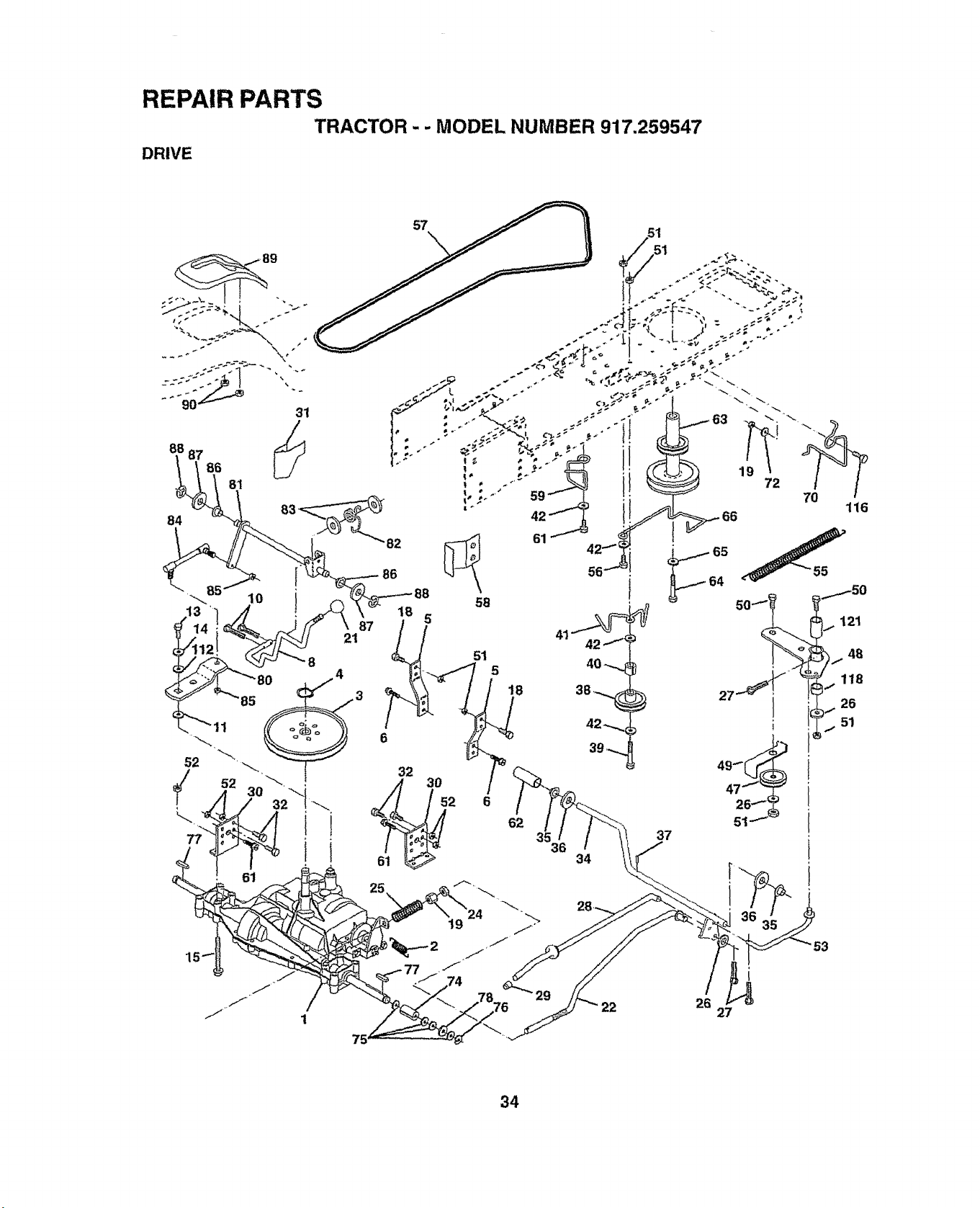
REPAIR PARTS
TRACTOR - - MODEL NUMBER 917,259547
DRIVE
57
31
88 87
86
81
_82
87
21
88
58
18 5
51
5
6
19
6
62
61
56
18
35
34
29
65
64
37
1 72
116
27
121
)i. 48
118
26
51
53
i
26
27
34
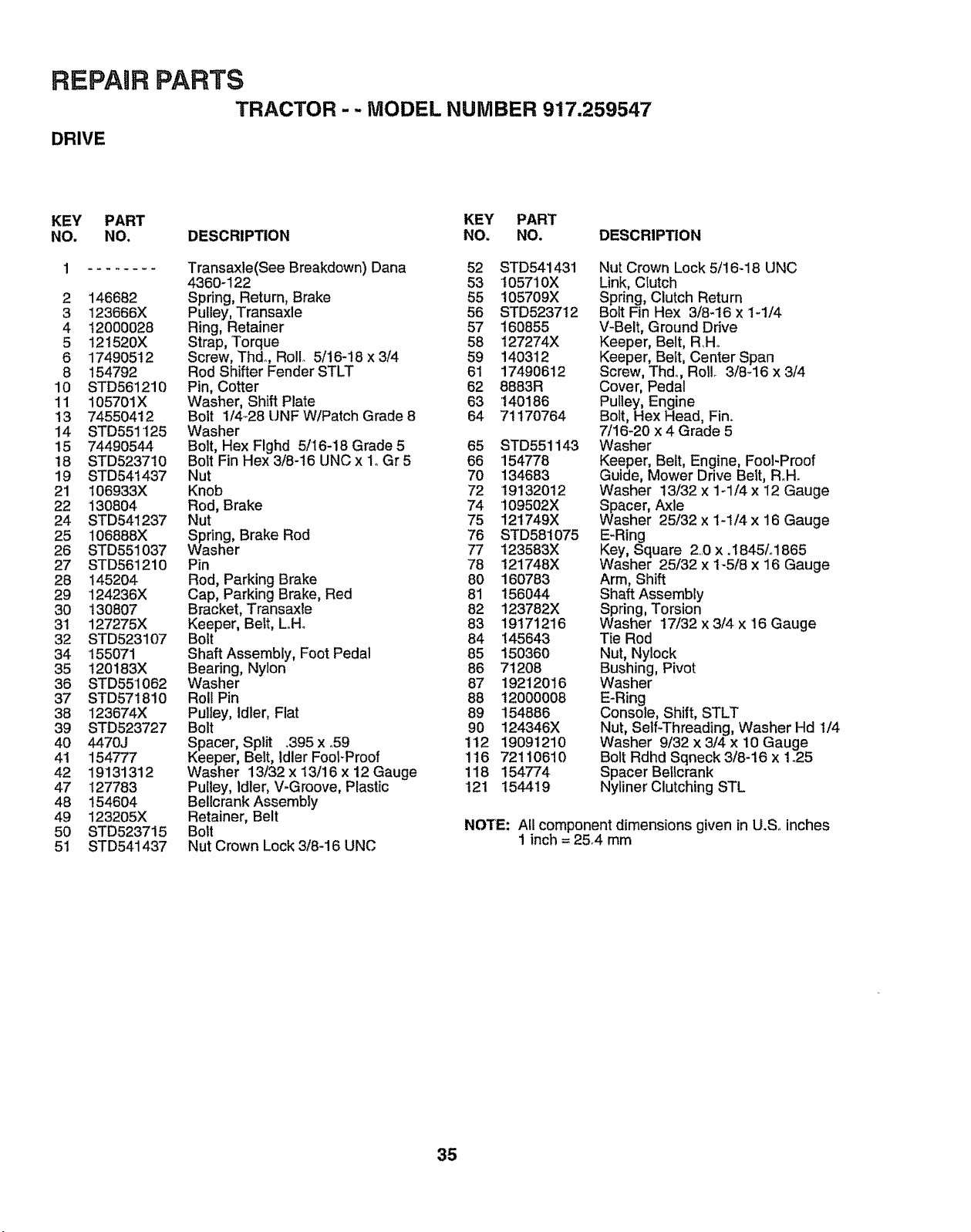
REPAIR PARTS
TRACTOR - - MODEL NUMBER 917.259547
DRIVE
KEY PART KEY PART
NO. NO. DESCRIPTION NO. NO, DESCRIPTION
1 ........ Transaxle(See Breakdown) Dana 52 STD541431
4360-122 53 105710X
2 146682 Spdng, Return, Brake 55 105709X
3 123666X Pulley, Transaxle 56 STD523712
4 12000028 Ring, Retainer 57 160855
5 121520X Strap, Torque 58 127274X
6 17490512 Screw, Thd+, Roll. 5/16-18 x 3/4 59 140312
8 !54792 Rod Shifter Fender STLT 6I 17490612
10 STD561210 Pin, Cotter 62 8883R
11 105701X Washer, Shift Plate 63 '140186
13 745504t2 Bolt 1/4+28 UNF W/Patch Grade 8 64 7!170764
14 STD551125 Washer
15 74490544 Bolt, Hex Flghd 5/'16-18 Grade 5 65 STD551143
t8 STD523710 Bolt Fin Hex 3/8-t6 UNC x 1. Gr 5 66 154778
19 STD541437 Nut 70 134683
21 106933X Knob 72 19132012
22 130804 Rod, Brake 74 109502X
24 STD541237 Nut 75 121749X
25 106868X Spring, Brake Rod 76 STD581075
26 STD551037 Washer 77 123583X
27 STD561210 Pin 78 121748X
28 145204 Rod, Parking Brake 80 160783
29 124236X Cap, Parking Brake, Red 81 156044
30 130807 Bracket, Transaxle 82 123782X
31 127275X Keeper, Belt, L..H. 83 19171216
32 STD523107 Bolt 84 I45643
34 155071 Shaft Assembly, Foot Pedal 85 150360
35 t20183X Bearing, Nylon 86 71208
36 STD551062 Washer 87 19212016
37 STD57!810 Roll Pin 88 12000008
38 123674X Pulley, Idler, Flat 89 154886
39 STD523727 Bolt 90 124346X
40 4470J Spacer, Split +395x _59 112 19091210
4t 154777 Keeper, Belt, ldlerFoot+Proof 1t6 72110610
42 19131312 Washer 13/32 x 13/16 x 12 Gauge 118 154774
47 127783 Pulley, Idler, V-Groove, Plastic 121 154419
48 154604 Bellcrank Assembly
49 123205X Retainer, Belt
50 STD523715 Bolt
51 STD541437 Nut Crown Lock 3/8-16 UNC
Nut Crown Lock 5/16-18 UNC
Link, Clutch
Spring, Clutch Return
Bolt Fin Hex 3/8_16 x 1-1/4
V-Belt, Ground Drive
Keeper, Belt, R.H°
Keeper, Beit, Center Span
Screw, Thd+, Roll+ 3/8-16 x 3/4
Cover, Pedal
Pulley, Engine
Bolt, Hex Head, Fin+
7/16-20 x 4 Grade 5
Washer
Keeper, Belt, Engine, Fool-Proof
Guide, Mower Drive Belt, R.H+
Washer 13/32 x 1+1/4 x 12 Gauge
Spacer, Axle
Washer 25/32 x 1-1/4 x 16 Gauge
E-Ring
Key, Square 2.0 x .t845L1865
Washer 25/32 x 1-5/8 x 16 Gauge
Arm, Shift
Shaft Assembly
Spring, Torsion
Washer 17/32 x 3/4 x 16 Gauge
Tie Rod
Nut, Nylock
Bushing, Pivot
Washer
E-Ring
Console, Shift, STLT
Nut, Self+Threading, Washer Hd 1/4
Washer 9/32 x 3/4 x 10 Gauge
Bolt Rdhd Sqneck 3/8-16 x i+25
Spacer Bellcrank
Nytiner Clutching STL
NOTE: All component dimensions given in U+Soinches
1 inch = 25+4 mm
35
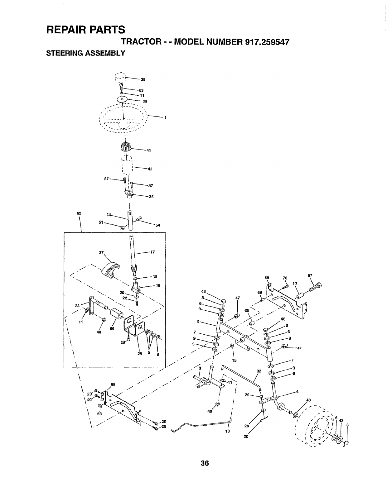
REPAIR PARTS
TRACTOR- - MODEL NUMBER 917.259547
STEERING ASSEMBLY
' 37
\
\
\
46
67
9__6a 70 13
6
47
15 tJ
32
28
3O
36
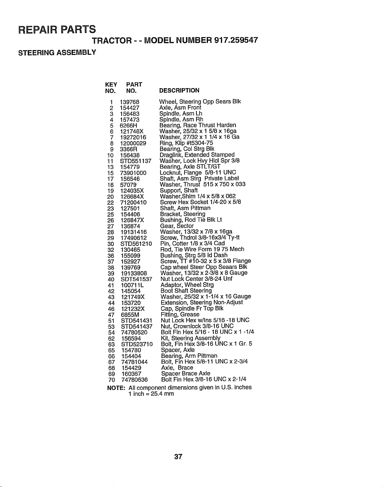
REPAIR PARTS
TRACTOR - - MODEL NUMBER 917.259547
STEERING ASSEMBLY
KEY PART
NO. NO. DESCRIPTION
1 !39768
2 154427
3 156483
4 157473
5 6266H
6 121748X
7 19272016
8 12000029
9 3366R
t0 156438
11 STD551137
13 154779
15 73901000
17 156546
I8 57079
19 124035X
20 t26684X
22 71200410
23 127501
25 154406
26 126847X
27 136874
28 19131416
29 17490612
3O STD5612!0
32 130465
36 155099
37 152927
38 139769
39 19133808
4O SDT541537
41 100711L
42 145054
43 121749X
44 t53720
46 !21232X
47 6855M
51 STD54t431
53 STD541437
54 74780520
62 t56594
63 STD523710
65 154780
66 154404
67 74781044
68 154429
69 160367
70 74780636
Wheel, Steering Opp Sears Blk
Axle, Asm Front
Spindle, Asm Lh
Spindle, Asm Rh
Bearing, Race Thrust Harden
Washer, 25/32 x 1 5/8 x 16ga
Washer, 27/32 x I 1/4 x 16 Ga
Ring, Klip #t5304-75
Bearing, Col Strg BIk
Draglink, Extended Stamped
Washer, Lock Hvy Hlcl Spr 3/8
Bearing, Axle STLT/GT
Locknut, Flange 5/8-11 UNC
Shaft, Asm Strg Private Label
Washer, Thrust 515 x 750 x 033
Support, Shaft
Washer, Shim 1/4 x 5/8 x 062
Screw Hex Socket 1/4-20 x 5/8
Shaft, Asm Pittman
Bracket, Steering
Bushing, Rod Tie BIk Lt
Gear, Sector
Washer, 13/32 x 7/8 x 16ga
Screw, Thdrol 3/8-16x3/4 Ty-tt
Pin, Cotter 1/8 x 3/4 Cad
Rod, Tie Wire Form 19 75 Mech
Bushing, Strg 5/8 Id Dash
Screw, TT #10-32 x 5 x 3/8 Flange
Cap wheel Steer Opp Seaars Bik
Washer, 13/32 x 2-3/8 x 8 Gauge
Nut Lock Center 3/8-24 Unf
Adaptor, Wheel Strg
Boot Shaft Steering1/4
Washer, 25/32 x - x 16 Gauge
Extension, Steering Non-Adjust
Cap, Spindle Fr Top BIk
Fitting, Grease
Nut Lock Hex w/ins 5/16 -18 UNC
Nut, Crowntock 3/8-16 UNC
Bolt Fin Hex 5/16 - t8 UNC x 1 -1/4
Kit, Steering Assembly
Bolt, Fin Hex 3/8-16 UNC x I Gro5
Spacer, Axle
Bearing, Arm Pittman
Bolt, Fin Hex 5/8-11 UNC x 2-3/4
Axle, Brace
Spacer Brace Axle
Bolt Fin Hex 3/8-16 UNC x 2-1/4
NOTE: All component dimensions given in U.Soinches
1 inch = 25,.4 mm
37
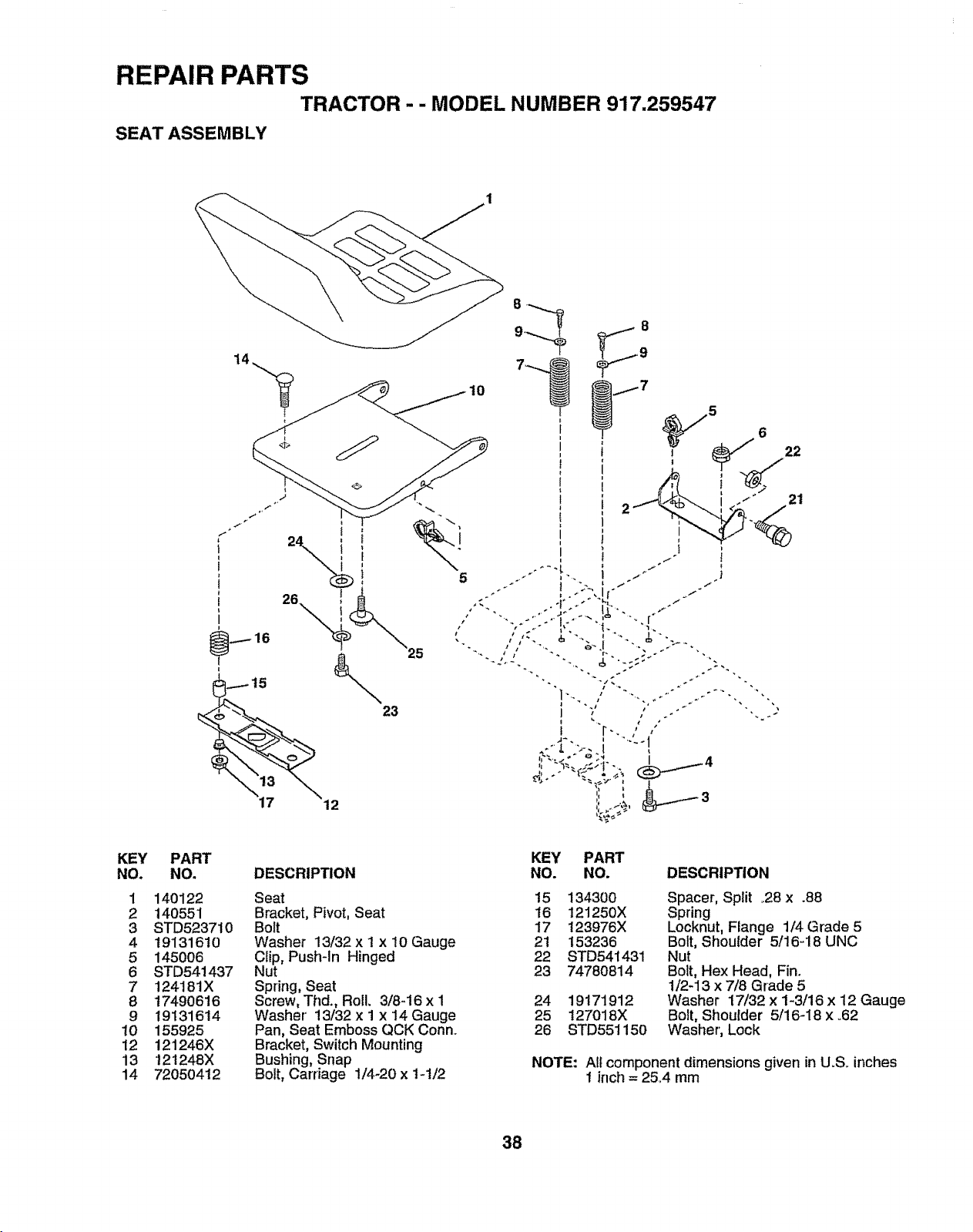
REPAIR PARTS
TRACTOR - - MODEL NUMBER 917.259547
SEAT ASSEMBLY
5
.
i
I
i
J
t
1
I
l
I
i
I
i
KEY
NO.
1
2
3
4
5
6
7
8
9
10
12
13
14
PART
NO.
140122
140551
STD523710
19131610
145006
8TD5414-37
124181X
17490616
19131614
155925
121246X
12t 248X
72050412
DESCRIPTION
Seat
Bracket, Pivot, Seat
Bolt
Washer 13/32 x I x 10 Gauge
Clip, Push-in Hinged
Nut
Spring, Seat
Screw, Thd., Roll. 3/8-16 x 1
Washer' 13/32 x 1 x 14 Gauge
Pan, Seat Emboss QCK Conn..
Bracket, Switch Mounting
Bushing, Snap
Bolt, Carriage 1/4-20 x 1-1/2
KEY PART
NO. NO. DESCRIPTION
15 134300
16 121250X
17 123976X
21 153236
22 STD541431
23 7478O814
24 19171912
25 127018X
26 STD551150
Spacer, Split 28 x .88
Spring _' de
Locknut, Flange 1/4 Gra 5
Bolt, Shoulder 5/16-18 UNC
Nut
Bolt, Hex Head, Fin.
1/2-13 x 7/8 Grade 5
Washer 17/32 x 1-3/16 x 12 Gauge
Bolt, Shoulder 5/16-18 x °62
Washer', Lock
NOTE: All component dimensions given in U.S, inches
1 inch = 2&4 mm
38
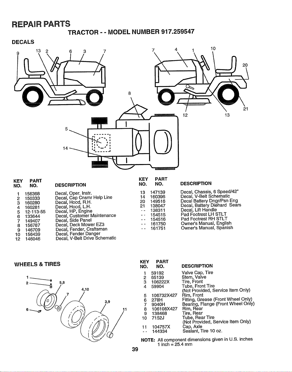
REPAIR PARTS
TRACTOR- - MODEL NUMBER 917.259547
DECALS
13 2 6 3 7 7 4 i
9
10
2O
8
14
12 13
21
KEY PART
NO. NO.
'1 156368
2 150333
3 160280
4 160281
5 12-113-55
6 133644
7 149407
8 156787
9 146709
10 156439
12 146046
DESCRIPTION
Decal, Oper. Instr.
Decal, Cap Cnsmr Help Line
Decal, Hood, R..Ho
Decal, Hood, L.H..
Decal, HP, Engine
Decal, Customer Maintenance
Decal, Side Panel
Decal, Deck Mower EZ3
Decal, Fender, Craftsman
Decal, Fender Danger
Decal, V-Belt Drive Schematic
KEY PART
NO. NO.
13 147139
14 160396
20 149516
21 138047
-- 138311
-- 154515
-- 154516
-- 16175O
-- 161751
DESCRIPTION
Decal, Chassis, 6 Speed/42"
Decal, V-Belt Schematic
Decal Battery Dngr/Psn Eng
Decal, Battery Diehard Sears
Decal, Lift Handle
Pad Footrest LH STLT
Pad Footrest RH STLT
Owner's Manual, English
Owner's Manual, Spanish
WHEELS & TIRES
5,8
4,10
11
39
KEY PART
NO. NO.
1 59192
2 65139
3 106222X
4 59904
5 106732X427
6 278H
7 9040H
8 106108X427
9 138468
10 7152J
11 104757X
-- 144334
DESCRIPTION
Valve Cap, Tire
Stem, Valve
Tire, Front
Tube, Front Tire
(Not Provided, Service Item On_y)
Rim, Front
Fitting, Grease (Front Wheel Only)
Bearing, Flange (Front Wheel Only)
Rim, Rear
Tire, Rear
Tube, Rear Tire
(Not Provided, Service Item Only)
Cap, Axle
Sealant, Tire 10 oz..
NOTE: All component dimensions given in U,S. inches
1 inch= 25.4 mm
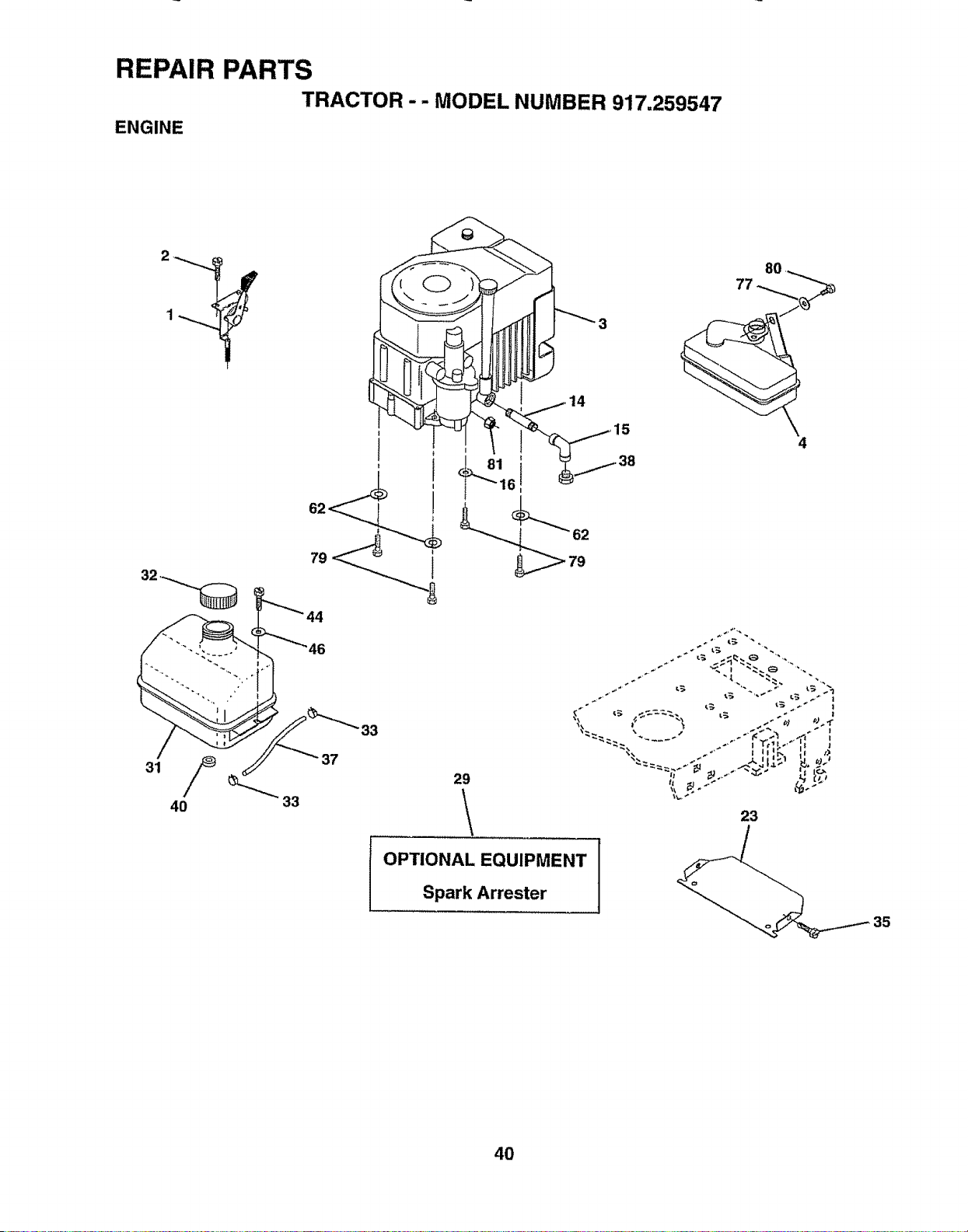
\ \
\
\
,,_ _ i_ ,_ ._ _
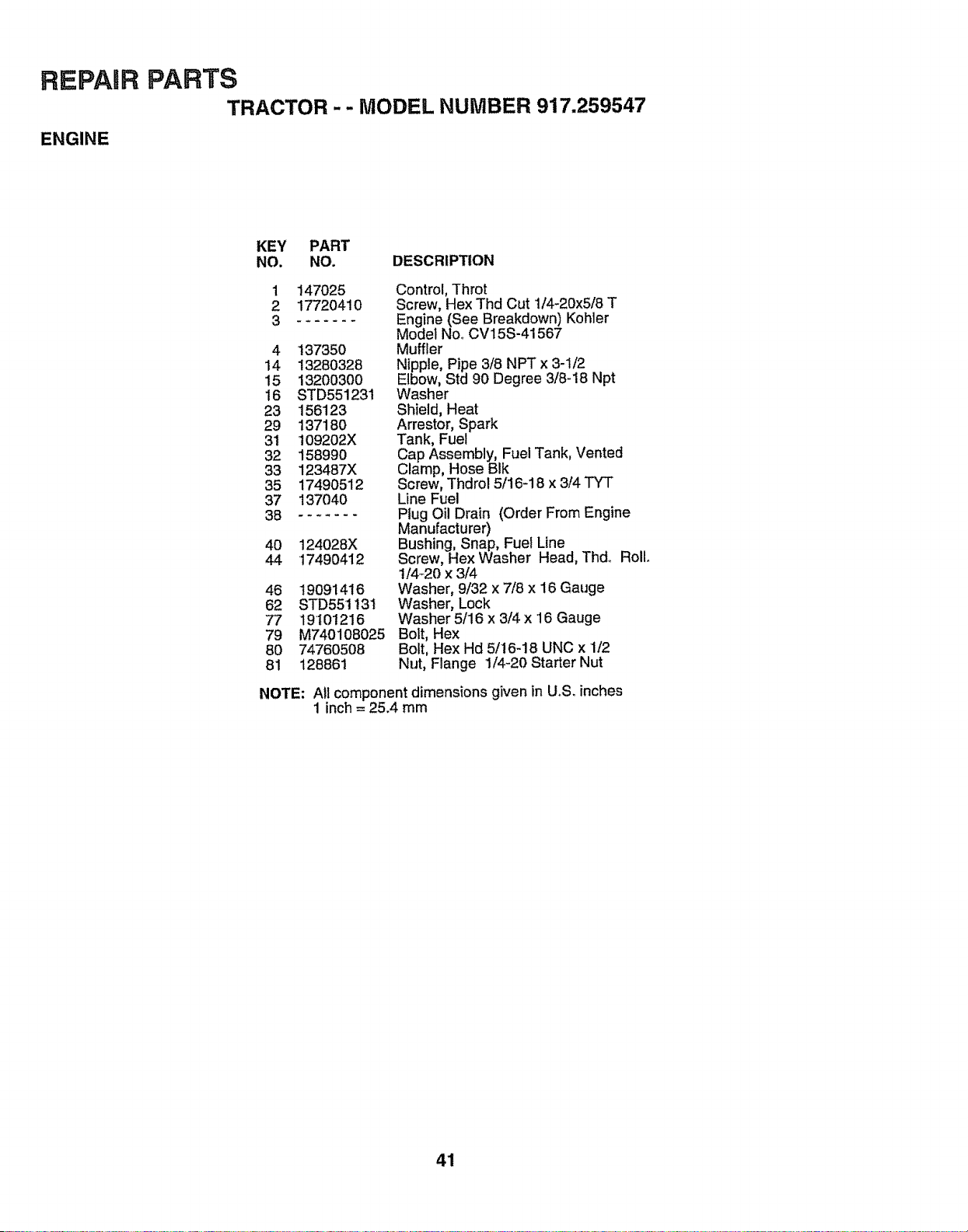
REPAIR PARTS
TRACTOR - - MODEL NUMBER 917.259547
ENGINE
KEY PART
NO. NO. DESCRIPTION
1 147025
2 177204t0
._ .....
4 137350
14 13280328
15 132003OO
16 STD551231
23 156123
29 13718O
31 109202X
32 158990
33 123487X
35 17490512
37 137040
38 .......
40 124028X
44 1749O412
46 19091416
62 STD551!3I
77 19101216
79 M740108025
80 74760508
81 128861
NOTE:
Control, Throt
Screw, Hex Thd Cut 1/4-20x5/8 T
Engine (See Breakdown) Kohler
Model No.. CV15S-41567
Muffler
Nipple, Pipe 3/8 NPT x 3-1/2
Elbow, Std 90 Degree 3/8-18 Npt
Washer
Shield, Heat
Arrestor, Spark
Tank, Fuel
Cap Assembly, Fuel Tank, Vented
Clamp, Hose BIk
Screw, Thdrol 5/16-18 x 3/4 TYT
Line Fuel
Plug Oil Drain (Order From Engine
Manufacturer)
Bushing, Snap, Fuel Line
Screw, Hex Washer Head, Thd., Roll
t/4_20 x 3/4
Washer, 9/32 x 7/8 x 16 Gauge
Washer, Lock
Washer 5/16 x 3/4 x '16Gauge
Bolt, Hex
Bolt, Hex Hd 5/!6-18 UNC x 1/2
Nut, Flange 1/4-20 Starter Nut
All component dimensions given in UoS.inches
1 inch = 25.4 mm
41
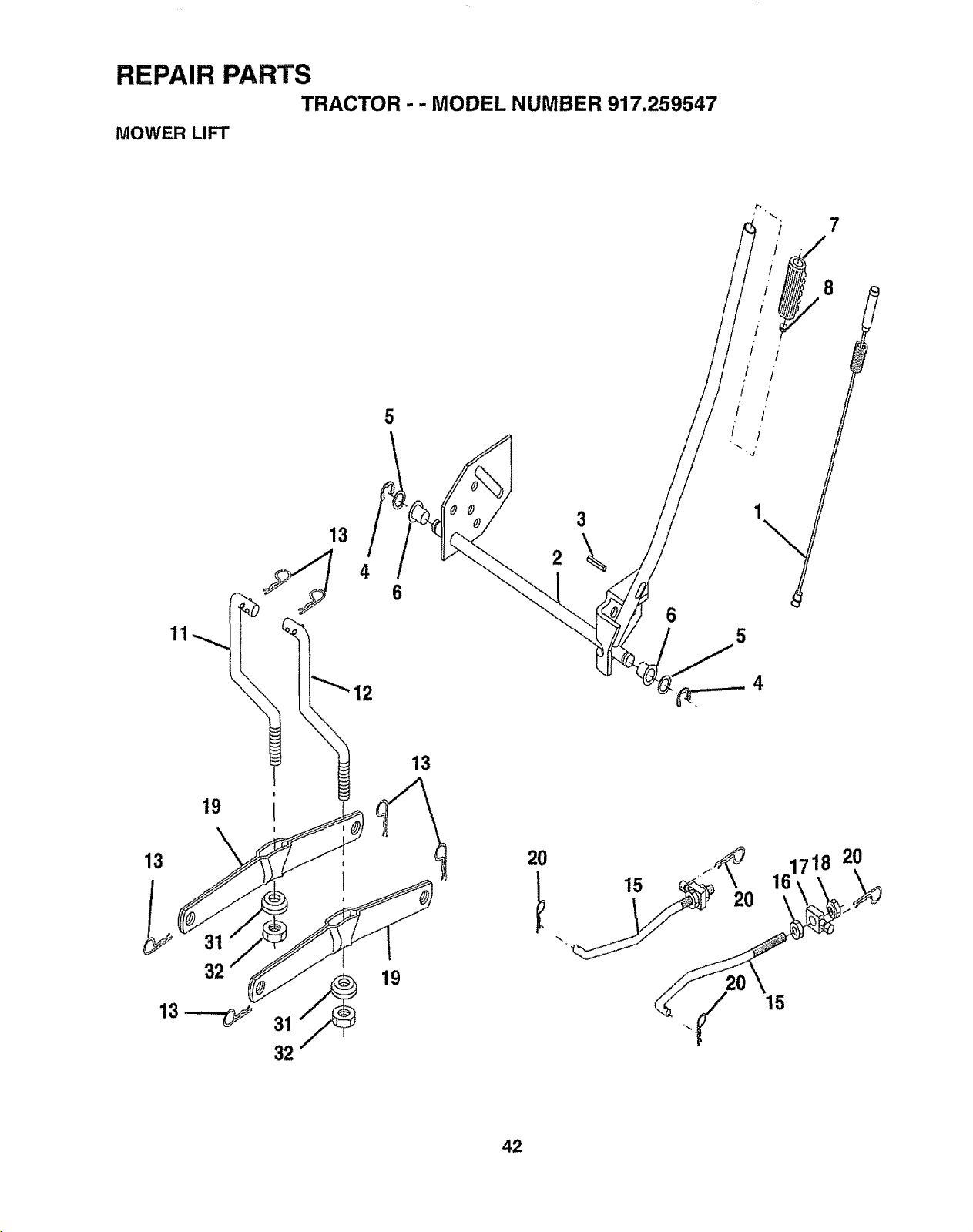
REPAIR PARTS
TRACTOR - - MODEL NUMBER 917.259547
MOWER LIFT
7
11
5
3
13
6
13
I
|
19 I
20
15
20
718 20
15
42

REPAIR PARTS
TRACTOR -- MODEL NUMBER 917,259547
MOWER LIFT
KEY PART
NO, NO. DESCRIPTION
1 15946O
2 159471
3 105767X
4 12000002
5 19211621
6 120183X
7 125631X
8 122365X
11 139865
12 139866
13 STD624008
15 127218
16 73350800
17 130171
18 STD541450
19 139868
20 STD624008
31 140302
32 73540600
Wire Asm Inner/Spring W/Plngr LT
Shaft Asmo Lift
Pin Groove
E Ring #5133-62
Washer 21/32 x 1 x 21 Ga,,
Bearing Nylon
Grip Handle Fluted
Button Plunger Red
Link Lift Lh Fixed Length
Link Lift Rh Fixed Length
Retainer Spring
Link Front
Nut Jam Hex 1/2-13 Uric
Trunnion BIk Zinc
LockNut, Hex, with Washer Insert
t/2-13 UNC
Arm, Suspension Rear
Retainer Spring
Bearing, Pivot, Lift Spherical
Nut, Crown!ock 3/8-24
NOTE: All component dimensions given in U.S, inches
t inch = 25.4 mm
43
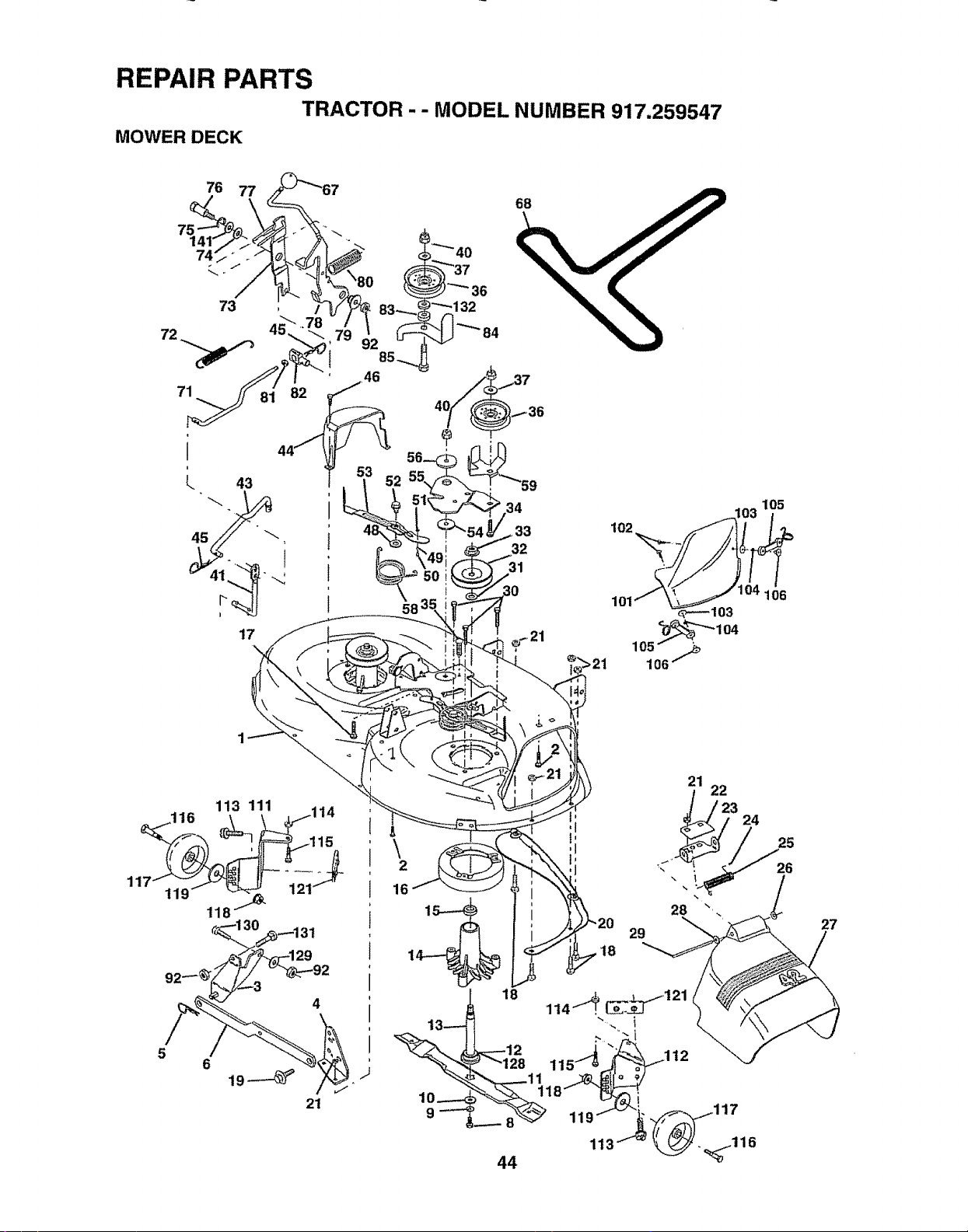
REPAIR PARTS
TRACTOR -- MODEL NUMBER 917.259547
MOWER DECK
76
17
68
34
•33
32
31
102
105
'106
\
2
16
18
29
21 22
_23 24
28
27
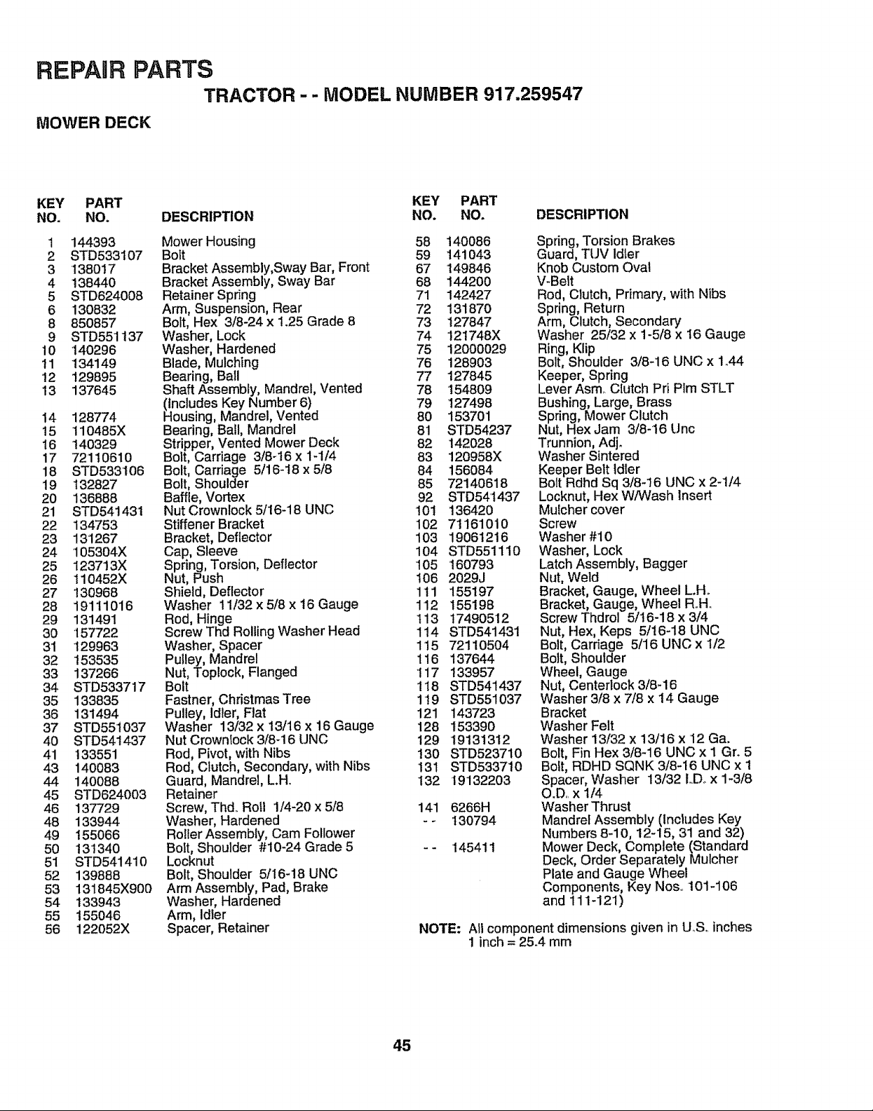
REPAIR PARTS
TRACTOR-- MODEL NUMBER 917.259547
MOWER DECK
KEY PART KEY PART
NO. NO. DESCRIPTION NO. NO. DESCRIPTION
1 144393
2 STD533107
3 138017
4 138440
5 STD624008
6 130832
8 85O857
9 STD551t37
10 140296
11 134149
12 129895
13 137645
14 128774
15 110485X
16 140329
17 72110610
18 STD533106
19 132827
20 136888
21 STD541431
22 134753
23 131267
24 105304X
25 123713X
26 110452X
27 130968
28 19111O16
29 131491
30 157722
31 129963
32 153535
33 137266
34 STD533717
35 133835
36 131494
37 STD551037
40 STD541437
41 133551
43 140083
44 14OO88
45 STD624003
46 137729
48 133944
49 155066
50 13134O
51 STD541410
52 139888
53 131845X900
54 133943
55 155O46
56 122052X
Mower Housing 58
Bolt 59
Bracket Assembly,Sway Bar, Front 67
Bracket Assembly, Sway Bar 68
Retainer Spring 71
Arm, Suspension, Rear 72
Bolt, Hex 3/8-24 x 1.25 Grade 8 73
Washer, Lock 74
Washer, Hardened 75
Blade, Mulching 76
Bearing, Bail 77
Shaft Assembly, Mandrel, Vented 78
HlnCludesKey Number 6) 79
ousing, Mandrel, Vented 80
Bearing, Ball, Mandrel 81
Stripper, Vented Mower Deck 82
Bolt, Carriage 3/8-16 x 1-I/4 83
Bolt, Carriage 5/16-18 x 5/8 84
Bolt, Shoulder 85
Baffle, Vortex 92
Nut Crownlock 5/16-18 UNC 101
Stiffener Bracket 102
Bracket, Deflector 103
Cap, Sleeve 104
Spring, Torsion, Deflector 105
Nut, Push t06
Shield, Deflector 111
Washer 11/32 x 5/8 x 16 Gauge 112
Rod, Hinge 113
Screw Thd Roiling Washer Head 114
Washer, Spacer 115
Pulley, Mandrel 116
Nut, Toplock, Flanged 117
Bolt ! 18
Fastner, Christmas Tree 119
Pulley, Idler, Flat 121
Washer 13/32 x 13/16 x i6 Gauge 128
Nut Crownlock 3/8-16 UNC 129
Rod, Pivot, with Nibs 130
Rod, Clutch, Secondary, with Nibs 131
Guard, Mandrel, L.H.. 132
Retainer
Screw, Thd.. Roll 1/4-20 x 5/8 141
Washer, Hardened - -
Roller Assembly, Cam Follower
Bolt, Shoulder #t0-24 Grade 5 - -
Locknut
Bolt, Shoulder 5/16-18 UNC
Arm Assembly, Pad, Brake
Washer, Hardened
Arm, Idler
Spacer, Retainer NOTE:
140086
141043
149846
144200
142427
13187O
127847
!21748X
12000029
128903
127845
'154809
127498
153701
STD54237
142028
120958X
156084
72140618
STD541437
136420
71161010
19061216
STD551110
160793
2029J
155197
155198
17490512
STD541431
72110504
137644
133957
STD541437
STD551037
143723
153390
'19131312
STD523710
STD5337t0
19132203
6266H
130794
145411
Spring, Torsion Brakes
Guard, TUV Idler
Knob Custom Oval
V-Belt
Rod, Clutch, Primary, with Nibs
Spring, Return
Arm, Clutch, Secondary
Washer 25/32 x 1-5/8 x 16 Gauge
Ring, Kiip
Bolt, Shoulder 3/8-16 UNC x 1o44
Keeper, Spring
Lever Asm_ Clutch Pri Plm STLT
Bushing, Large, Brass
Spring, Mower Clutch
Nut, Hex Jam 3/8-16 Unc
Trunnion, Adj.
Washer Sintered
Keeper Belt Idler
Bolt Rdhd Sq 3/8-16 UNC x 2-1/4
Locknut, Hex W/Wash Insert
Mulcher cover
Screw
Washer #10
Washer, Lock
Latch Assembly, Bagger
Nut, Weld
Bracket, Gauge, Wheel L.Ho
Bracket, Gauge, Wheel R.Ho
Screw Thdrol 5/16-18 x 3/4
Nut, Hex, Keps 5/16-18 UNC
Bolt, Carriage 5/16 UNC x t/2
Bolt, Shoulder
Wheel, Gauge
Nut, Centerlock 3/8-16
Washer 3/8 x 7/8 x 14 Gauge
Bracket
Washer Felt
Washer 13/32 x 13/16 x '12 Ga.
Bolt, Fin Hex 3/8-16 UNC x I Gn 5
Bolt, RDHD SQNK 3/8-16 UNC x 1
Spacer, Washer 13/32 LDo x 1-3/8
O.D.. x 1/4
Washer Thrust
Mandrel Assembly (IncttJdes Key
Numbers 8-10, 12-15, 31 and 32)
Mower Deck, Complete (Standard
Deck, Order Separately Mulcher
Plate and Gauge Wheel
Components, Key Nos.. 101-106
and 111-121 )
All component dimensions given in U_Soinches
1 inch = 25.4 mm
45
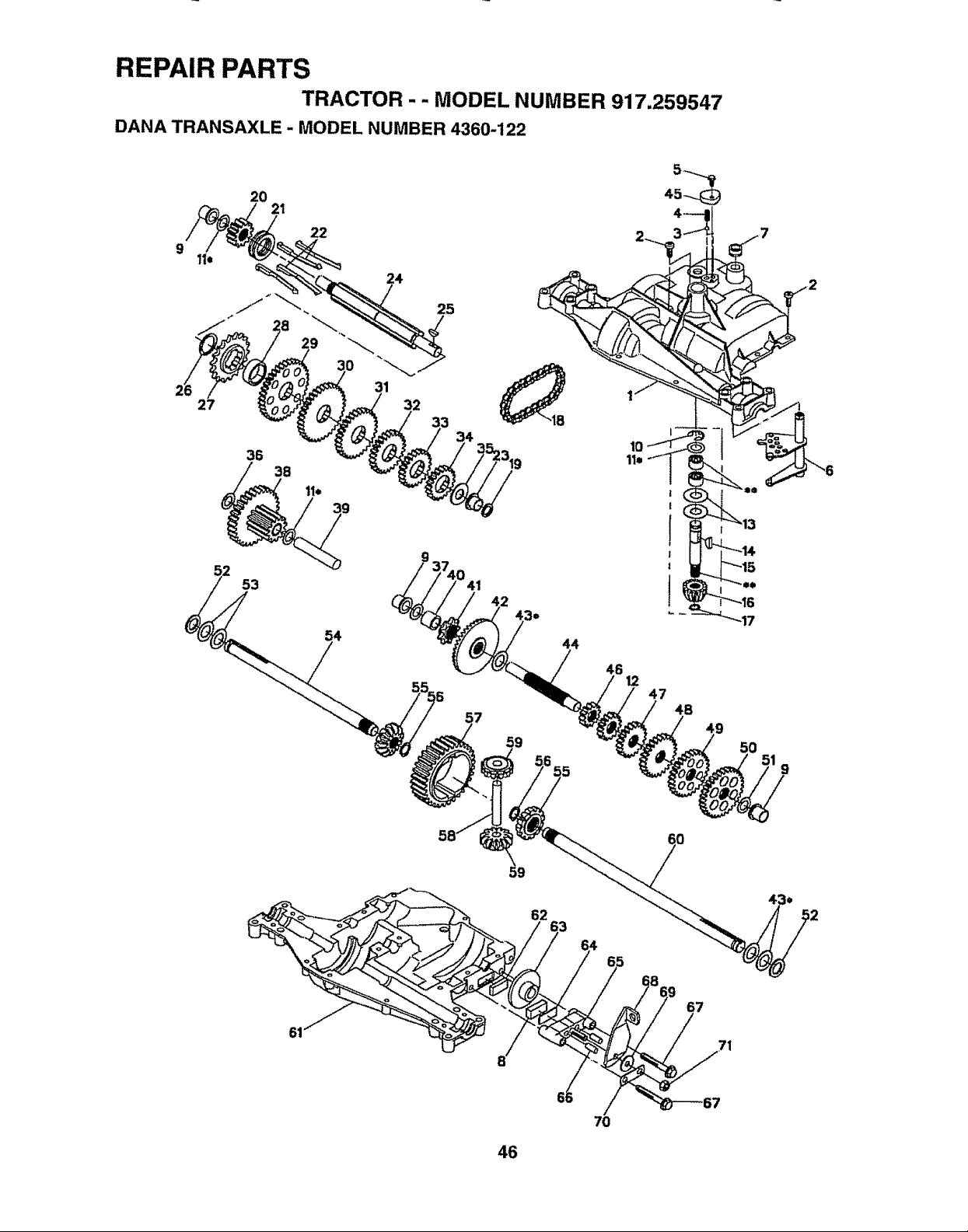
REPAIR PARTS
TRACTOR - - MODEL NUMBER 917,259547
DANA TRANSAXLE - MODEL NUMBER 4360-122
9
27
20
2t
36
22
24
31
25
t0
11=
53
54
47
4B
9
_9
62
46

REPAIR PARTS
TRACTOR - - MODEL NUMBER 917.259547
DANA TRANSAXLE - MODEL NUMBER 4360-122
KEY PART KEY PART
NO. NO, DESCRIPTION NO, NO. DESCRIPTION
1 160955 Housing, Upper 37 2231J
2 2274J Screw, Tapping, 1/4-20 X .734 38 160944
3 134400 Ball, Detent 39 124639X
4 105904X Spring, Detent 40 120472X
5 160940 Screw, Tapping, Noo 10_24 X 482 41 I05928X
6 134788 Assy, Kit, Shifter 42 161565
7 108727X V-Ring 43 134394
8 12095'1X Puck, Friction 44 120473X
9 148266 Bearing, Flange 45 160942
10 2225J Ring, Retaining 46 142678
11 134793 Assy, Kit, Shim, .625 Shaft 47 124641X
t2 143697 Gear, Spur, 15T 48 106589X
'13 120415X Washer, Plain, ..632X 1o38X .046 49 120408X
14 t42674 Key, Woodruff, Noo9 50 105937X
15 161563 Assy, Kit, input Shaft 51 2226J
16 161564 Pinion, Bevel, 12T 52 134401
17 '105909X Ring, Retaining 53 2264J
18 105910X Chain, 24 Pitches 54 160946
19 148269 Seal, Oil 55 160947
20 160943 Gear, Spur, 12T 56 160948
21 138246 Collar, Clutch 57 110071X
22 138238 Assy, Kit, Clutch Keys 58 120952X
23 148268 Bearing, Flange 59 160949
24 143673 Shaft, Intermediate 60 160950
25 2244J Key, Woodruff, No. 61 61 160951
26 105916X Ring, Retaining 62 120961X
27 t20470X Sprocket, t8T 63 7294J
28 110070X Spacer, 1_131 X 1.45X.494 64 !08989X
29 142677 Gear, Spur, 37T 65 t60952
30 142681 Gear, Spur, 35T 66 120954X
31 124644X Gear, Spur, 30T 67 t60953
32 !08980X Gear, Spur, 25T 68 138244
33 t20406X Gear, Spur, 22T 69 108996X
34 !34796 Gear, Spur, t9T 70 160954
35 105925X Washer, Plain, .640 X 1o37X .06'1 71 73810500
36 2228J Washer, Plain, o632X 1.00 X .046 72 120416X
Washer, Plain, .632 X 1.00 X .031
Assy, Gear, Comb, 12T & 30T
Shaft, Idler
Spacer, .633 X 87 X _755
Sprocket, 9T
Gear, Bevel, 36T
Assy, Kit, Shim, °750 Shaft
Shaft, Drive
Cover, Detent
Gear, Spur, 12T
Gear, Spur, 20T
Gear, Spur, 25T
Gear, Spur, 28T
Gear, Spur, 31T
Washer, Plain, .632 X 1.00 X .060
Washer, Neoprene
Washer, Plain, °758 X 1.25 X o031
Axle, LH
Gear, Miter, 12T, Splined
Ring, Retaining
Gear, Spur, 32T
Shaft, Cross
Gear, Miter, 12T, Idler
Axle, RH
Housing, Lower
Puck, Friction
Disc, Brake
Spacer, Brake Puck
Jaw, Brake
Pin, Dowel
Screw, Tapping, 5/16-18 X 2.35
Lever, Actuating
Washer, Plain, .321 X 1.00 X .055
Bracket, Anti-Rotation
Nut, Lock, 5/16-24
Grease
NOTE: Al! component dimensions given in UoSoinches
1 inch = 25.4 mm
47
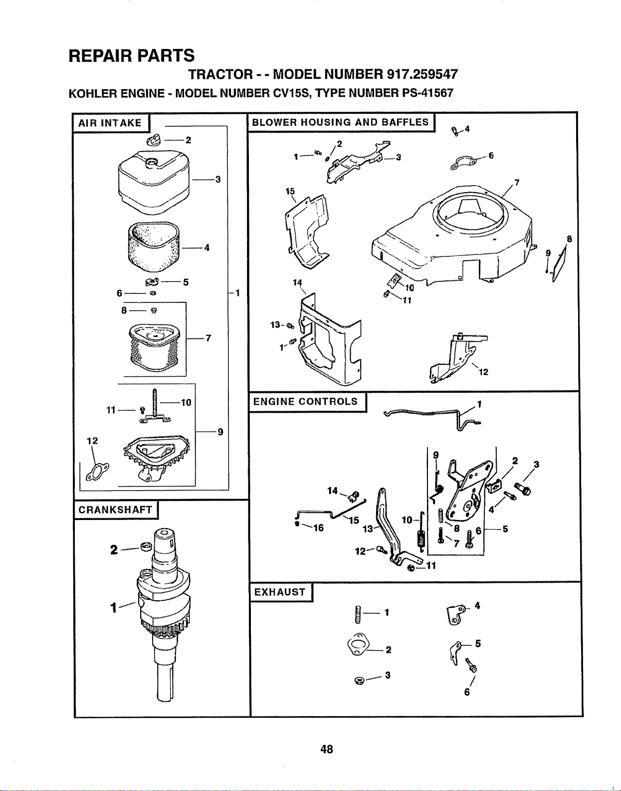
REPAIR PARTS
TRACTOR-- MODEL NUMBER 917,259547
KOHLER ENGINE - MODEL NUMBER CV15S, TYPE NUMBER PS-41567
AIR INTAKE
12
__4
_5
6_o
8_@ !
I
!
i
_9
CRANKSHAFT 1
2 _..----_ _
I j
i !
BLOWER HOUSING AND BAFFLES
15
_4
t4
9
1
.-r::=:-z_'ls tLt lO-r
0"'16 13
/
6
8
48
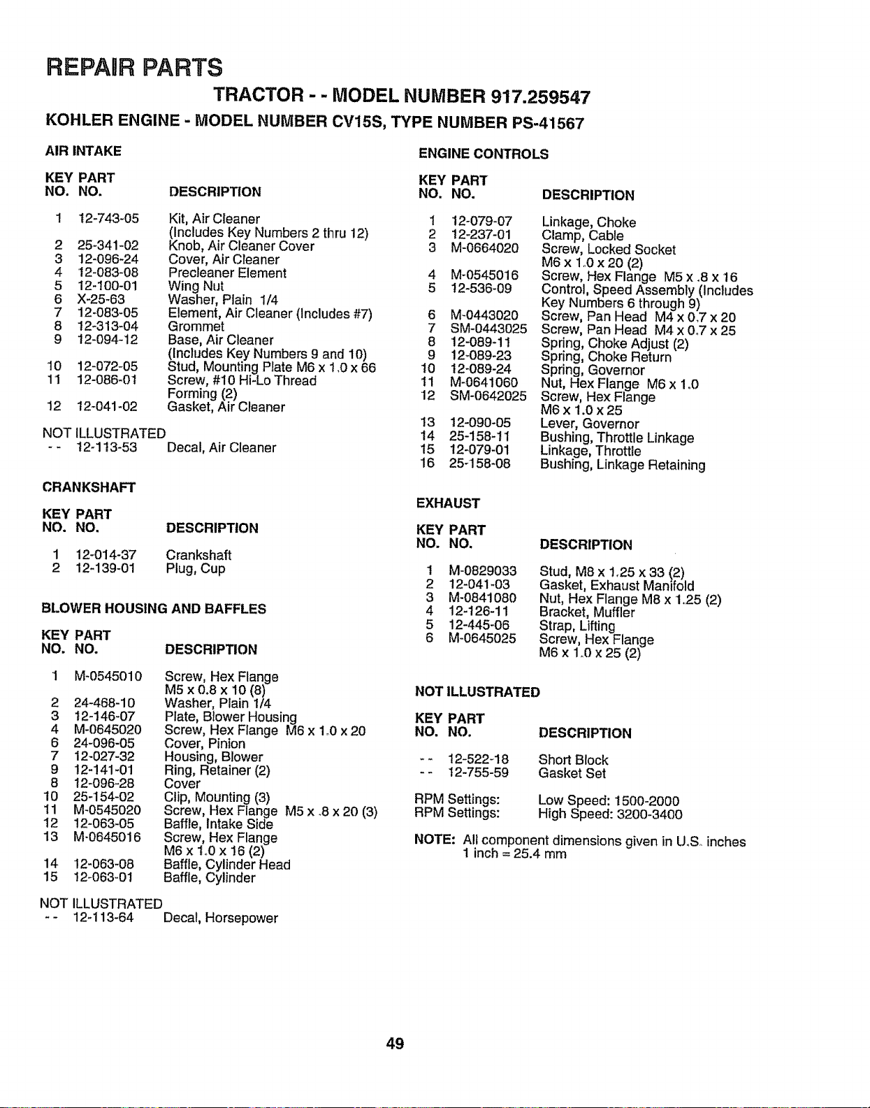
REPAIR PARTS
TRACTOR - - MODEL NUMBER 917.259547
KOHLER ENGINE - MODEL NUMBER CV15S, TYPE NUMBER PS-41567
AIR INTAKE
ENGINE CONTROLS
KEY PART KEY PART
NO. NO. DESCRIPTION NO. NO.
12-743-05
2 25-341-02
3 !2-096-24
4 12-083-08
5 12-100-01
6 X-25-63
7 12-083-05
8 t2-313-04
9 t2-094-12
10 12-072-05
11 12-086-01
12 t2-041-02
NOT
Kit, Air Cleaner 1
(Includes Key Numbers 2 thru 12) 2
Knob, Air Cleaner Cover 3
Cover, Air Cleaner
Precleaner Element 4
Wing Nut 5
Washer, Plain 1/4
Element, Air Cleaner (Includes #7) 6
Grommet 7
Base, Air Cleaner 8
(Includes Key Numbers 9 and 10) 9
Stud, Mounting Plate M6 x 1,0 x 66 10
Screw, #10 Hi-Lo Thread 11
Forming (2) 12
Gasket, Air Cleaner
ILLUSTRATED
12-113-53 Decal, Air Cleaner
CRANKSHAFT
KEY PART
NO. NO.
1 12-014-37
2 12-139-01
DESCRIPTION
Crankshaft
Plug, Cup
BLOWER HOUSING AND BAFFLES
KEY PART
NO. NO. DESCRIPTION
1 M_0545010 Screw, Hex Flange
M5 x 0.8 x 10 (8)
2 24-468-10 Washer, Plain 1/4
3 t2-146-07 Plate, Blower Housing
4 M-0645020 Screw, Hex Flange M6 x 1o0x 20
6 24-096-05 Cover, Pinion
7 12-027-32 Housing, Blower
9 !2-141-01 Ring, Retainer (2)
8 12-096-28 Cover
10 25-154-02 Clip, Mounting (3)
11 M-0545020 Screw, Hex Flange M5 x .8 x 20 (3)
12 12-063-05 Baffle, Intake Side
13 M-0645016 Screw, Hex Flange
M6 x to0 x 16 (2)
14 12-063-08 Baffle, Cylinder Head
15 12-063-01 Baffle, Cylinder
NOT ILLUSTRATED
12q 13-64 Decal, Horsepower
12-079-07
12-237-01
M-0664020
M-0545016
12-536-09
M-0443020
SM-0443025
12-089-11
12-089-23
12-089-24
M-0641060
SM-0642025
13 12-090-05
14 25-158-tl
15 12-079-01
16 25-158-08
DESCRIPTION
Linkage, Choke
Clamp, Cable
Screw, Locked Socket
M6 x 1,,0 x 20 (2)
Screw, Hex Flange M5 x .8 x 16
Control, Speed Assembly (Includes
Key Numbers 6 through 9)
Screw, Pan Head M4 x 0.7 x 20
Screw, Pan Head M4 x 0°7 x 25
Spring, Choke Adjust (2)
Spring, Choke Return
Spring, Governor
Nut, Hex Flange M6 x 1o0
Screw, Hex Flange
M6 x 1.0 x 25
Lever, Governor
Bushing, Throttle Linkage
Linkage, Throttle
Bushing, Linkage Retaining
EXHAUST
KEY PART
NO. NO.
1 M-0829033
2 12-041_03
3 M-0841080
4 12-126-11
5 12-445-06
6 M-0645025
DESCRIPTION
Stud, M8 x 1.25 x 33 (2)
Gasket, Exhaust Manifold
Nut, Hex Flange M8 x 1,25 (2)
Bracket, Muffler
Strap, Lifting
Screw, Hex Flange
M6 x 1,.0x 25 (2)
NOT ILLUSTRATED
KEY PART
NO. NO.
* 12-522_18
- - 12-755-59
RPM Settings:
RPM Settings:
DESCRIPTION
Short Block
Gasket Set
Low Speed: t500-2000
High Speed: 3200-3400
NOTE: All component dimensions given in UoSoinches
1 inch = 25.4 mm
49
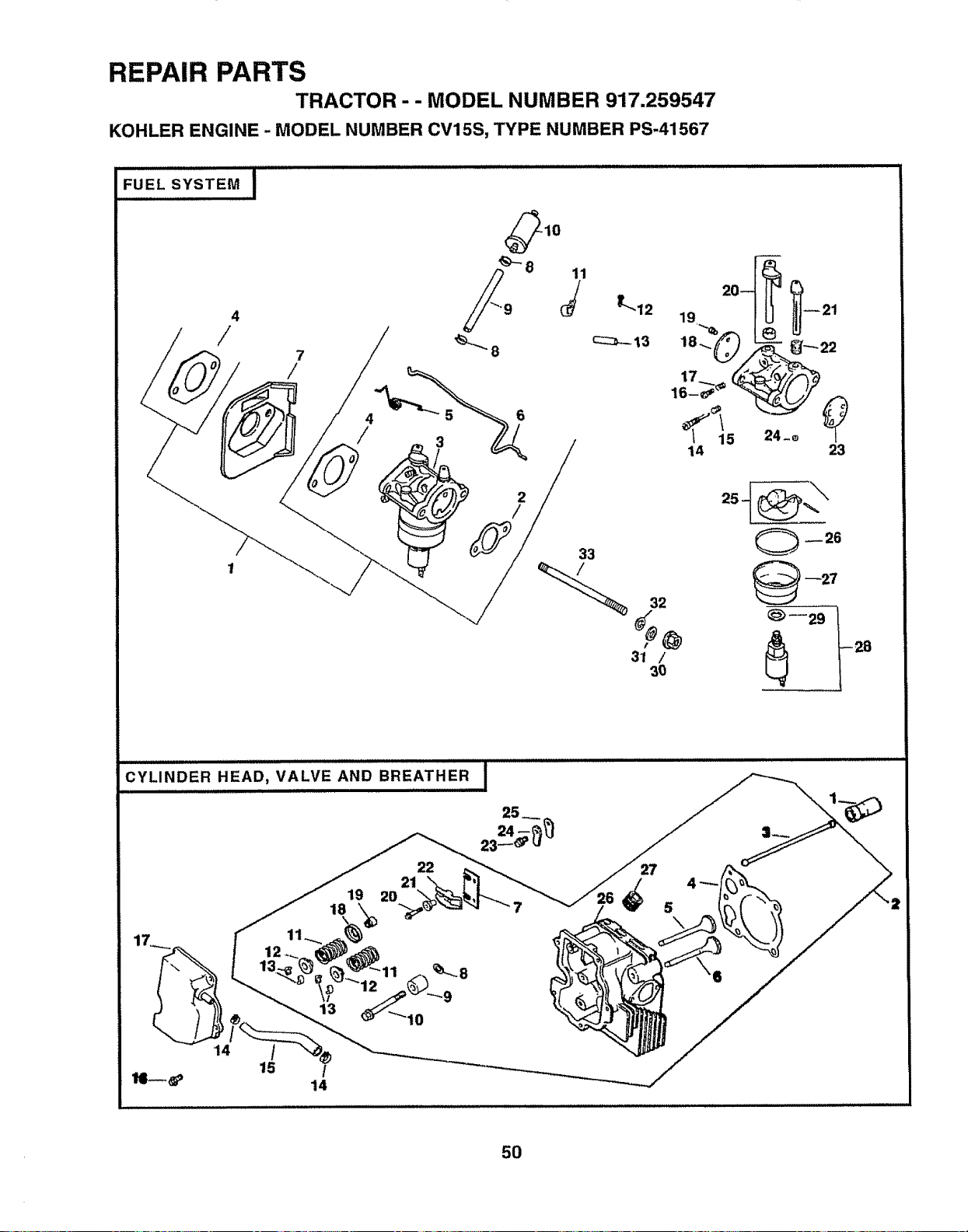
REPAIR PARTS
TRACTOR-- MODEL NUMBER 917.259547
KOHLER ENGINE - MODEL NUMBER CV15S, TYPE NUMBER PS-41567
2
/
33
19,..._ 21
14 23
32
31 /
3O
28
CYLINDER HEAD, VALVE AND BREATHER
.................................. i
19
18
22
21
20
12
13
27
\
50
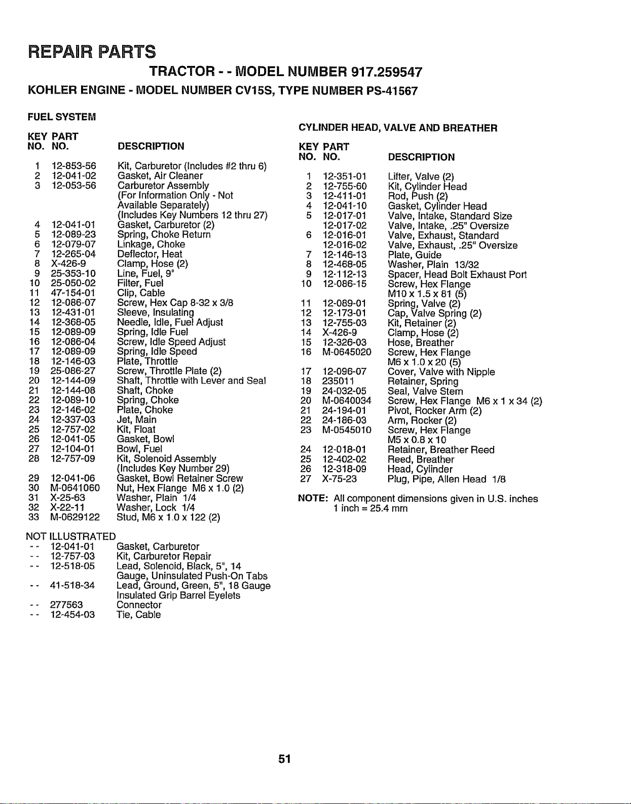
REPAIR PARTS
TRACTOR - - MODEL NUMBER 917.259547
KOHLER ENGINE - MODEL NUMBER CV15S, TYPE NUMBER PS-41567
FUEL SYSTEM
KEY PART
NO. NO. DESCRIPTION
CYLINDER HEAD, VALVE AND BREATHER
KEY PART
NO. NO. DESCRIPTION
1 t2-853-56 Kit, Carburetor (Includes #2 thru 6)
2 t2-041-02 Gasket, AirCleaner 1 12-351-01
3 t2-053-56 Carburetor Assembly 2 12-755-60
(For Information Only - Not 3 12-411-01
Available Separately) 4 12-041-10
(Includes Key Numbers 12 thru 27) 5 I2-0t7-0t
4 12-041-01 Gasket, Carburetor (2) 12-017-02
5 12-089-23 Spring, Choke Return 6 12-016-01
6 12-079-07 Linkage, Choke 12-016-02
7 12-265-04 Deflector, Heat 7 12_146-13
8 X-426-9 Clamp, Hose (2) 8 12-468-05
9 25-353-10 Line, Fuel, 9" 9 12-112-13
10 25-050-02 Filter, Fuel 10 12-086-15
11 47-154-01 Clip, Cable
12 12-086-07 Screw, Hex Cap 8_32 x 3/8 11 12-089-01
13 12-43'!-01 Sleeve, Insulating 12 12-173-01
14 12-368-05 Needle, Idle, Fuel Adjust 13 12-755-03
15 12-089_09 Spring, Idle Fuel 14 X-426-9
16 12-086-04 Screw, Idle Speed Adjust 15 t2-326-03
17 12-089-09 Spring, Idle Speed 16 M-0645020
18 12-146-03 Plate, Throttle
19 25-086-27 Screw, Throttle Plate (2) t7 12-096-07
20 12-144-09 Shaft, Throttle with Lever and Seal 18 235011
21 12-144-08 Shaft, Choke 19 24-032-05
22 t2-089-10 Spring, Choke 20 M-0640034
23 t2-146-02 Plate, Choke 21 24-194-01
24 t2-337-03 Jet, Main 22 24-186-03
25 12-757-02 Kit, Float 23 M-0545010
26 12-04t-05 Gasket, Bowl
27 12-I04-01 Bowl, Fuel 24 12-0!8-01
28 12-757-09 Kit, Solenoid Assembly 25 12-402-02
(includes Key Number 29) 26 12-318-09
29 !2-041-06 Gasket, Bowl Retainer Screw 27 X-75-23
30 M-0641060 Nut, Hex Flange M6 x 1.0 (2)
31 X-25-63 Washer, Plain 1/4
32 X-22-11 Washer, Lock 1/4
33 M-0629122 Stud, M6 x I..0 x 122 (2)
ILLUSTRATED
12-041-01 Gasket, Carburetor
•12-757-03 Kit, Carburetor Repair
•I2-518-05 Lead, Solenoid, Black, 5", t4
Gauge, Uninsulated Push-On Tabs
4!-518-34 Lead, Ground, Green, 5", 18 Gauge
insulated Grip Barrel Eyelets
277563 Connector
12_454-03 Tie, Cable
NOT
Lifter, Valve (2)
Kit, Cylinder Head
Rod, Push (2)
Gasket, Cylinder Head
Valve, Intake, Standard Size
Valve, Intake, ,25" Oversize
Valve, Exhaust, Standard
Valve, Exhaust, .25" Oversize
Plate, Guide
Washer, Plain 13/32
Spacer, Head Bolt Exhaust Port
Screw, Hex Flange
M10 x 1.5 x 81 (5)
Spring, Valve (2)
Cap, Valve Spring (2)
Kit, Retainer (2)
Clamp, Hose (2)
Hose, Breather
Screw, Hex Flange
M6 x 1_0x 20 (5)
Cover, Valve with Nipple
Retainer, Spring
Seal, Valve Stem
Screw, Hex Flange M6 x I x 34 (2)
Pivot, Rocker Arm (2)
Arm, Rocker (2)
Screw, Hex Flange
M5x0o8x 10
Retainer, Breather Reed
Reed, Breather
Head, Cylinder
Plug, Pipe, Allen Head 1/8
NOTE: All component dimensions given in UoS° inches
1 inch = 25.4 mm
51

REPAIR PARTS
TRACTOR - - MODEL NUMBER 917.259547
KOHLER ENGINE - MODEL NUMBER CV15S, TYPE NUMBER PS-41567
IGNITION / ELECTRICAL !
17 ,...? 11
\
_10
13 __..,
OIL PAN / LUBRICATION I
,!
23
22 2
8
9
@
0
1
2
52
REPAIR PARTS
TRACTOR - - MODEL NUMBER 917.259547
KOHLER ENGINE - MODEL NUMBER CV15S, TYPE NUMBER PS-41567
IGNITION / ELECTRICAL
CRANKCASE
KEY PART KEY PART
NO. NO. DESCRIPTION NO. NO. DESCRIPTION
1 12-038-01
1 12-086-14 Screw, Hex Flange 1 12-032-03
M10 x Io5 x 46 2 12-522-18
2 12-468-03 Washer, Plain 3/8 3 12-445-02
3 24_162-03 Screen, Grass 4 M_0839025
4 M-0639016 Screw, Hex Flange M6 x I x 16 (4) 5 12-380-03
5 12-t12-01 Spacer, Fan (4) 6 12-755_49
6 12_157-02 Fan 7 12-089-18
7 X-42-15 Key 8 12-422-08
8 12-025-37 Flywheel Assembly 12-422-09
9 12-155-02 Connector (4 Contact) 12-422-10
10 M-0548025 Screw, Hex Cap 12-422-!1
M5 x 0.8 x 25 (2) 12-422-12
1! M-0545010 Screw, Hex Flange 12-422-13
M5 x 0.8 x 10 (2) 12-422-07
12 12-154-02 Clip, Stator Harness 9 12-'144-27
'13 12-085-07 Stator Assembly 10 12-874-07
14 12-132-02 Spark Plug 12-874-08
15 X-728-1 Clip, Cable 12-874-09
16 12-584-01 Module, Ignition 1t 12-018-02
17 M-0545020 Screw, Hex Flange 12 12-108-07
M5 x 0.8 x 20 (2) 12-'108-08
t2-108-09
NOT iLLUSTRATED 13 12-067-05
- - 12-518-11 Lead, White, Ground To Kill (19", 12-067-06
18 Gauge, Fully insulated Push-on 14 12-380-01
Tab and Uninsulated Push-on Tab 15 12-043-05
Terminals) 16 M-0631005
17 12-144-02
OIL PAN / LUBRICATION 18 52-139-09
19 t2-755-64
KEY PART
NO. NO. DESCRIPTION 20 12-144-24
21 X-25-102
22 12-032_01
23 SM-0631015
24 12-154-05
2 25-755_13
3 12-153-03
4 12-153-02
5 12-123-04
6 M-0545020
7 12-153-01
8 25-162-07
9 !2-096-03
10 M-0545016
11 M-1039025
12 12-126-02
13 12-089-03
14 !2_462-01
15 12-208-01
16 12-050-01
17 X-75-10
18 12-393-0!
19 12-032-04
2O 12-096-02
21 M-0545016
22 12-032-03
23 SM-0839045
Dipstick Assembly
(Includes Key Numbers 2 and 3)
Kit, Oil Fill Cap (Includes Key #3)
O-Ring, Dipstick
O-Ring, Upp..erOil Fil! Tube
Tube, Oil Fftl
Screw, Hex Flange M5 x 0°8 x 20
O-Ring, Lower Oil Fill Tube
Screen, Oil Pick-up
Cover, Oil Pick-up Screen
Screw, Hex Flange M5 x 0.8 x 16
Screw, Hex Flange MIO x 1.5 x 25
Bracket, Oil Pump Relief Valve
Spring, Oil Pump Relief Valve
P_ston, Oi_Pump Relief Valve
Body, Oil Pump Relief Valve
Filter, Oil
Plug, Square Head, Solid 3/8
Oil Pump Assembly
O-Ring, Oil Pump Cover
Cover, Oil Pump
Screw, Hex Flange
M5 x 0.8 x 16 (3)
Seal, Oil (P..T.O. End)
Screw, Hex Flange
M8 x 1,25 x 45 (12)
Pan, Oil
53
24 12-199-30
Seal, Crankshaft
Block, Cylinder (Use Short Block)
Strap, Lifting
Screw, Hex Flange M8 x 1.25 x 25
Dowel, Locating (4)
Kit, Camshaft (Includes Key #7 & 8)
Spring, Actuating
Shim, Camshaft, Blue
Shim, Camshaft, Red (A.R.)
Shim, Camshaft, Yellow (AoR.)
Shim, Camshaft, Green (A.R°)
Shim, Camshaft, Grey (AR,)
Shim, Camshaft, Black (A.R.)
Shim, Camshaft, White (A.Ro)
Shaft, Balance
Piston wiRing Set, Standard
Piston w/Ring Set °25',',Oversize
Piston w/Ring Set .50 Oversize
Retainer, Piston Pin (2)
Ring Set, Standard
Ring Set .25" Oversize
Ring Set ..50"Oversize
Connecting Rod, Standard
Connecting Rod .25" Oversize
Pin, Governor Regulating
Gear, Governor Assembly
Washer, Plain, 6mm
Shaft, Governor Gear
Plug, Cup
Kit, Shaft, Governor Cross, with
Clip (Includes Key #20 and 24)
Shaft, Governor Cross
Washer, Plain 1/4
Seal, Governor Cross Shaft
Washer, Plain, 6turn
Clip, Hitch Pin
STARTING SYSTEM
KEY PART
NO. NO. DESCRIPTION
1 M-0839070 Screw, Hex Flange
M8 x 1.25 x 7O (2)
2 25-098°03 Starter Assembly
(Includes Key Numbers 3 thru 8)
3 12-755-54 Kit, Drive End
4 12-227-06 Cap, Drive End
5 45-170-03 Armature
7 12-227-1! End Cap, Commutator
8 12-086-25 Screw, Hex Flange
1/4-20 x 4-5/8 (2)
NOTE: All component dimensions given in U.S. inches
1 inch = 25.4 mm

54

SUGGESTED GUIDE FOR SiGHTiNG SLOPES FOR SAFE OPERATION
SIGHTING
GUIDE
I
_.CUT o.
ONLY RIDE UP AND DOWN HILL,
NOT ACROSS HILL
SIGHT AND HOLD THIS LEVEL WITH
SKY LINE OR TREE.
15 ° MAX.
i1,11111111iiiiiiiHI I IIIIIIII1'111' HII 'l'llllll
_ Operate your Tractor up and down the face of slopes (not I
_| _ greater than 15°), never across the face. Make turns gradu- !
_| _ ally to prevent tipping or loss of control. Exercise extreme i
ll caution when changing direction on slopes, i

OWNER'S
MANUAL
MODEL NO.
917.259547
IF YOU NEED
REPAIR SERVICE
OR PARTS:
FOR REPAIR SERVICE, CALL
THIS TOLL FREE NUMBER:
1-800-4-REPAIR
(1-800-473-7247)
FOR REPLACEMENT PARTS
INFORMATION AND
ORDERING, CALL THIS
TOLL FREE NUMBER:
1-800-FON-PART
(1-800-366-7278)
FOR CONSUMER ASSISTANCE
HOT LINE, CALL THIS
TOLL FREE NUMBER:
1-800-659-5917
CRAFTSMAN+
15.5 HP
ELECTRIC START
42" MOWER
6 SPEED TRANSAXLE
LAWN TRACTOR
Each tractor has its own model number., Each engine has
its own model number_
The model number for your tractor will be found on the
model plate located under' the seat.
The model number for your engine will be found on the
blower housing of the engine.
All parts listed herein may be ordered from any Sears,
Roebuck and Co. Service Center/Department and most Re-
tail Stores_
WHEN ORDERING REPAIR PARTS, ALWAYS GIVE THE
FOLLOWING INFORMATION:
• PRODUCT - TRACTOR
° MODEL NUMBER - 917.259547
• ENGINE MODEL NO. - CV15S TYPE NO. PS-41567
° PART NUMBER
• PAR3 DESCRIPTION
Your Sears merchandise has added value when you
consider Sears has service units nationwide staffed with
Sears trained technicians_°, professional technicians
specifically trained to insure that we meet our pledge to
you, we service what we seIlo
161750 8o28.97 RH
Printed in U.,S,.A.
IIIIIIIIIIIIIIIIIIIIIIIII IIIIIIIIIIIIIIIII


