Loading ...
Loading ...
Loading ...
15
Fireplace Installation
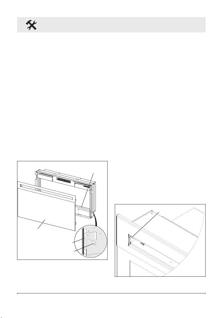
Figure 11
Front tray
Front glass
assembly
Figure 12
Tab
Hooks (4)
Mounts (4)
against the wall (Figure 9).
4. Use the supplied bubble level
to level the replace within the
framing, adjust as required.
5. Drive four supplied mounting
screws through the four mount-
ing holes located on the inside
surface of the replace chassis,
into wall studs (Figure 10).
6. Refer to Front Glass Installa-
tion section, page 15 for nal
installation procedures.
Front Glass Installation
1. Evenly distribute supplied
glass rock on the front tray of
the fireplace (Figure 11).
2. Carefully mount front glass
assembly so that the front
glass hooks hang on the front
glass mounts on the fireplace
(Figure 11).
3. Use the supplied two Phillips
sheet metal screws to fasten
the glass assembly tabs to the
fireplace (Figure 12).
4. Ensure the fireplace's On/Off
Switch is switched to the Off
position (refer to operation
section).
5. If unit is not hard-wired, plug
fireplace into a 15 Amp, 120
Volt outlet (refer to NOTE 1).
Loading ...
Loading ...
Loading ...